

Page 1
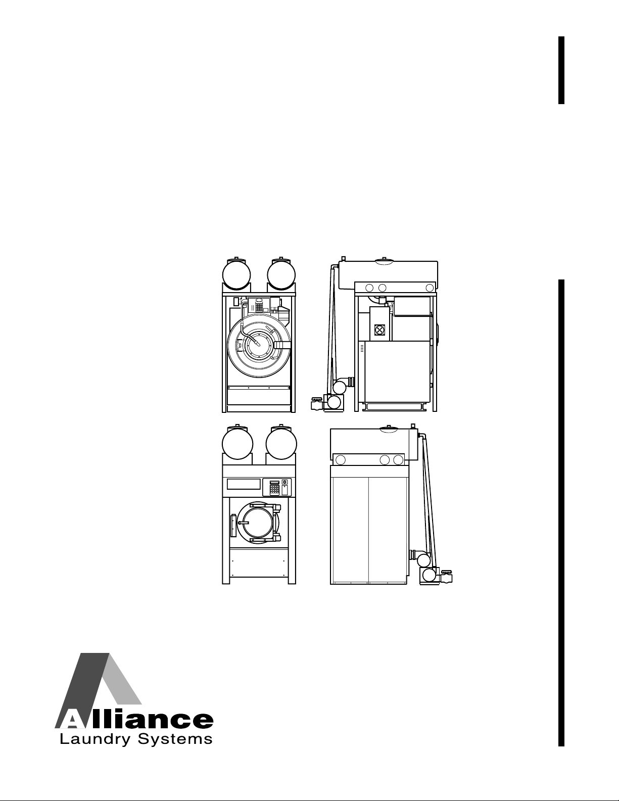
Water Saving System
Installation, Maintenance,
Operation and Programming
Instructions Supplement
Refer to Page 3 for Model Identification
UW
NOTA: El manual en
español aparece después
del manual en inglés.
Supplement
UF
Keep These Instructions for Future Reference.
(If this machine changes ownership, this manual must accompany machine.)
Q027I
Q027IE3A
Part No. F232122R3
October 2000
Page 2

Page 3

Table of
Introduction......................................................................................... 3
Model Identification ............................................................................. 3
Contents
Installation........................................................................................... 5
Dimensional Clearance......................................................................... 6
Machine Foundation ............................................................................. 8
Water Saving Tank Frame Foundation for Pocket
Hardmount Models (UWPV) ......................................................... 8
Mechanical Installation......................................................................... 9
Mounting Bolt Installation for Cabinet Freestanding
Models (UFPV) with
Water Saving System ..................................................................... 9
Mounting Bolt Installation for Pocket Hardmount
Models (UWPV) with Water Saving System................................. 9
Removing Top Section .................................................................... 11
Instructions for Installation of Pocket Hardmount
Models (UWPV) with Water Saving System..................................... 13
Tank Overflows ............................................................................... 18
Steam Heat Option........................................................................... 18
Instructions for Installation of Cabinet Freestanding
Models (UFPV) with Water Saving System ...................................... 19
Tank Overflows ............................................................................... 21
Maintenance ........................................................................................ 23
Daily ..................................................................................................... 23
Beginning of Day............................................................................. 23
End of Day ....................................................................................... 23
Weekly.................................................................................................. 23
Monthly................................................................................................. 23
Removal from Service ........................................................................ 25
Decommissioning ................................................................................. 25
Operation............................................................................................. 27
LED Display ......................................................................................... 27
Manual Mode Control Feature.............................................................. 27
Programming ...................................................................................... 29
Programming a Recovery Fill from Water Saving Tank(s).................. 29
Programming a Water Saving Drain Step ............................................ 29
Programming Cycles ............................................................................ 29
© Copyright 2000, Alliance Laundry Systems LLC
All rights reserved. No part of the contents of this book may be reproduced or transmitted in any form or by any
means without the expressed written consent of the publisher.
F232122
1
Page 4

Notes
2
F232122
Page 5

Introduction
Model Identification
Information in this manual is applicable to these models:
UW 60 PV
UW 100 PV
UF 35 PV
UF 50 PV
UF 85 PV
F232122
3
Page 6

Notes
4
F232122
Page 7
Installation
This manual is designed as a supplement to the
installation, maintenance, operation and programming
of PV model Pocket Hardmount and Cabinet
Freestanding washer-extractors equipped with the
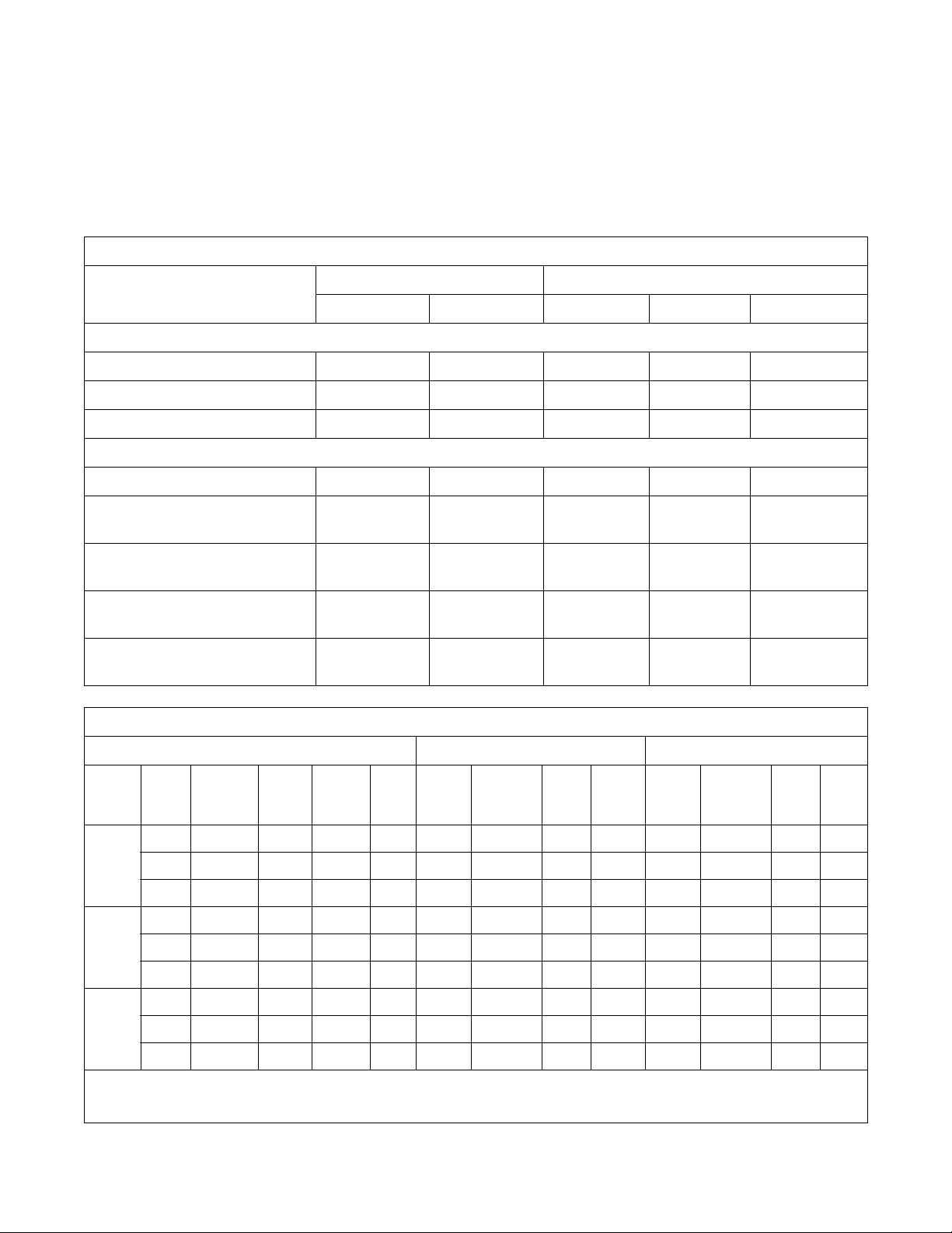
General Specifications for Models with Water Saving System
Models
Overall width, in (mm)
Overall height, in (mm)
Overall depth, in (mm)
Net weight, lb (kg)
Domestic shipping weight,
lb (kg)
Domestic shipping volume,
ft
3
(m3)
Pocket Hardmount Cabinet Freestanding
UW60PV UW100PV UF35PV UF50PV UF85PV
Overall Dimensions
41-7/16 (1053) 47-1/16 (1195) 35 (889) 39 (990.6) 46-1/2 (1181.1)
91 (2311) 95-5/8 (2429) 81-1/2 (2070) 85 (2159) 95-1/2 (2426)
61-3/4 (1568) 73-1/4 (1861) 54 (1392) 56.85 (1449) 65-3/4 (1670)
Weight and Shipping Information
1450 (657.7) 1810 (821) 1312 (595.1) 1700 (771.1) 3100 (1406.1)
1560 (707.6) 1935 (877.7) 1410 (639.6) 1800 (816.5) 3250 (1474.2)
207 (5.8) 212 (6.0) 137 (3.88) 143 (4.05) 201 (4.04)
Water Saving System (WSS). This manual should be
used in addition to the information found in manuals
with part numbers F232084, F232089, F232058 and
F232059 (supplied with the washer-extractor).
Export shipping weight,
lb (kg)
Export shipping volume,
Model Code Voltage Cycle Phase Wire
60
WSS
35
WSS
50
WSS
3
(m3)
ft
Electrical Specifications for Models with Water Saving System*
Voltage Designation Standard Electric Heat
N 440-480 50-60 3 3 6 15 14 3x2.5 33 40 8 3x10
P 380-415 50-60 3 3 6 15 14 3x2.5 29 40 8 3x10
Q 200-240 50-60 3 3 12 15 14 3x2.5 66 80 3 3x25
N 440-480 50-60 3 3 6 15 14 3x2.5 32 35 8 3x10
P 380-415 50-60 3 3 6 15 14 3x2.5 32 35 8 3x10
Q 200-240 50-60 3 3 12 15 14 3x2.5 50 50 8 3x10
N 440-480 50-60 3 3 6 15 14 3x2.5 43 50 8 3x10
P 380-415 50-60 3 3 6 15 14 3x2.5 43 50 8 3x10
Q 200-240 50-60 3 3 12 15 14 3x2.5 76 80 4 3x25
1600 (726) 2130 (967) 1500 (681) 1900 (863) 3350 (1521)
229 (6.5) 235 (6.7) 137 (3.88) 143 (4.05) 201 (5.69)
Full
Load
Amps
Breaker AWG mm
2
Full
Load
Amps
NOTE: Wire sizes shown are for copper, THHN, 90° conductor per NEC article 310.
Breaker AWG mm
2
*Voltage information for *UW80PVWSS mdoels is the same as that of standard UW80PV models.
F232122
5
Page 8
Installation
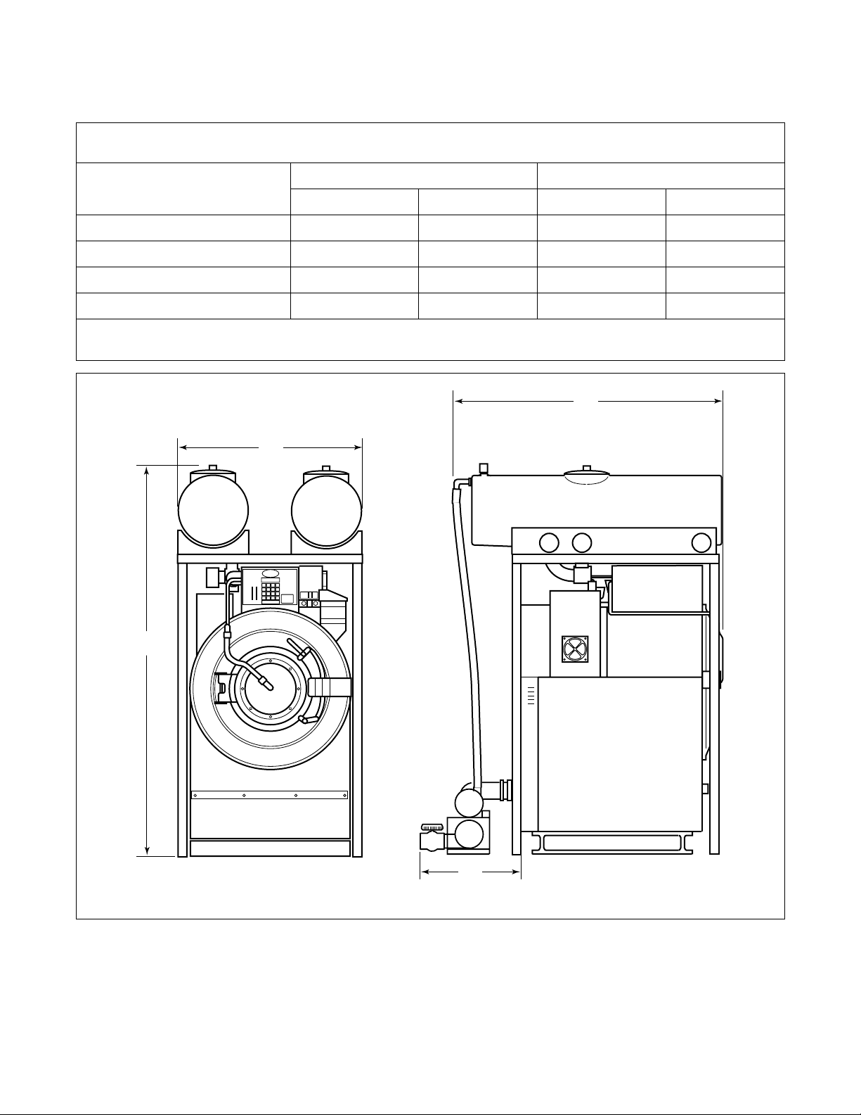
Dimensional Clearance
UWPV Pocket Hardmount with Water Saving System
Machine Dimensions*
Dimensions
60 100
in. mm in. mm
A
B
C
D
4-7/16 1052.5 47-1/16 1195.4
91 2311 95-5/8 2428.9
61-3/4 1568 73-1/4 1861
15-3/4 400 15-3/4 400
* Allow a minimum of 24 inches (610 mm) at the rear and 18 inches (460 mm) at the sides for maintenance, inspection and
adjustment. Allow at least 18 inches (460 mm) between machines in multiple installations.
C
A
B
D
Q020I
Q020I
6
F232122
Page 9
Installation
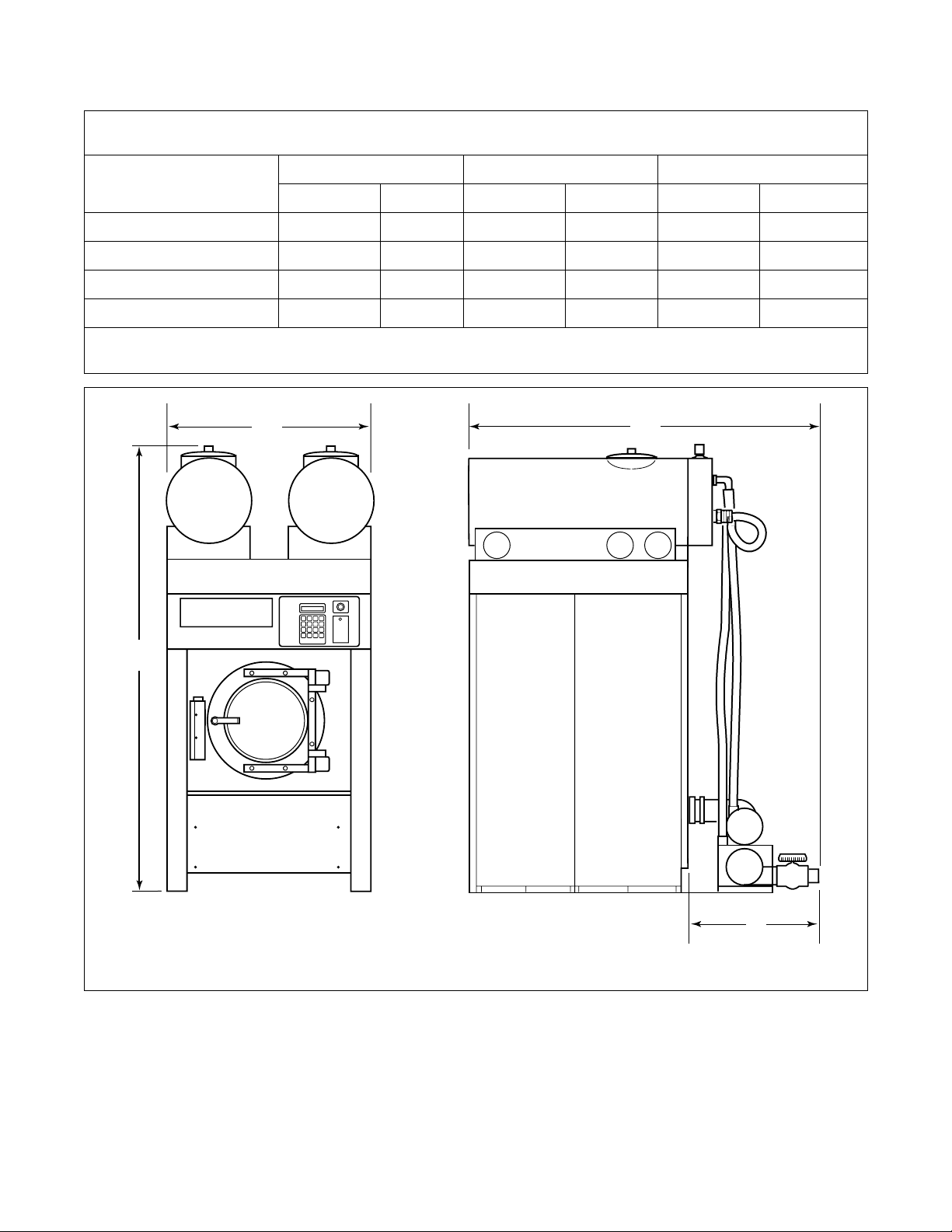
UFPV Cabinet Freestanding with Water Saving System
Machine Dimensions*
35 50 85
Dimensions
in. mm in. mm in. mm
A
B
C
D
35 889 39 990.6 46-1/2 1181.1
81-1/2 2070 85 2159 95-1/2 2426
57 1448 60-1/2 1537 68 1727
15-3/4 400 15-3/4 400 15-3/4 400
* Allow a minimum of 24 inches (610 mm) at the rear and 18 inches (460 mm) at the sides for maintenance, inspection and
adjustment. Allow at least 18 inches (460 mm) between machines in multiple installations.
A
C
B
D
Q002I
F232122
7
Page 10

Installation
Machine Foundation
For machine foundation information for both UWPV
and UFPV models, refer to section in respective
installation/maintenance manuals.
For UFPV models with the Water Saving System, refer
to Table 1 for total floor load data.
UFPV Cabinet Freestanding
Floor Load Data
35 50 85
Static floor load,
lbs (kN)
Static Pressure,
2
lbs/ft
(kN/m2)
Water Saving Tank Frame Foundation for
Pocket Hardmount Models (UWPV)
A proper frame foundation is absolutely necessary for
all UWPV washer-extractors with WSS because of the
water weight at elevated heights.
2193
(9.755)
231
(11.07)
Table 1
2675
(11.899)
239
(11.45)
5052
(22.472)
313
(15.00)
IMPORTANT: Ensure that the tank frame is
installed on a level floor of sufficient strength and
that the recommended clearances for inspection
and maintenance are provided. Never allow the
inspection and maintenance space to be blocked.
The tank frame must be anchored to a smooth level
surface so that all four legs are supported and rest on
the mounting surface.
If the washer-extractor installation will include the
WSS, the elevated base must be designed to
accommodate the additional width of 4 inches on each
side of the washer-extractor and correct alignment.
Static washer-extractor, tank and frame load on the
floor or foundation is shown in Tab le 2.
UWPV Pocket Hardmount
Floor Load Data
60 100
Static floor load,
lbs (kN)
Static pressure per leg,
lbs/ft
2
(kN/m2)
2617
(11.7)
227
(10.9)
4341
(19.3)
271
(13.0)
NOTE: Do not mount on wooden floors, above
ground level, or over basements. Installation must
be “slab on grade” or equal.
Table 2
8
F232122
Page 11
Installation
Mechanical Installation
Mounting Bolt Installation for Cabinet
Freestanding Models (UFPV) with
Water Saving System
Refer to the Installation/Maintenance manual
(P/N F232059) for mounting bolt installation
information for UFPV models.
Mounting Bolt Installation for Pocket
Hardmount Models (UWPV) with Water
Saving System
NOTE: The WSS frame must be permanently
attached to the floor.
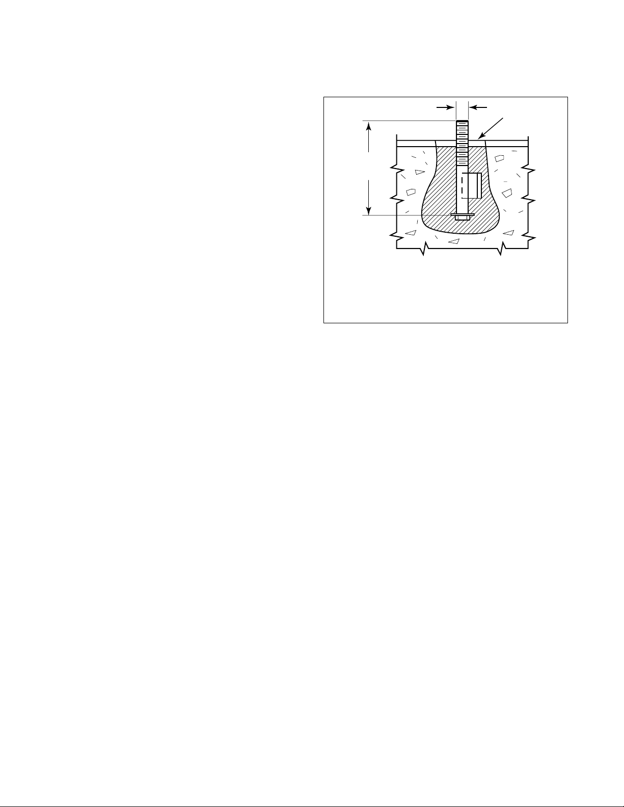
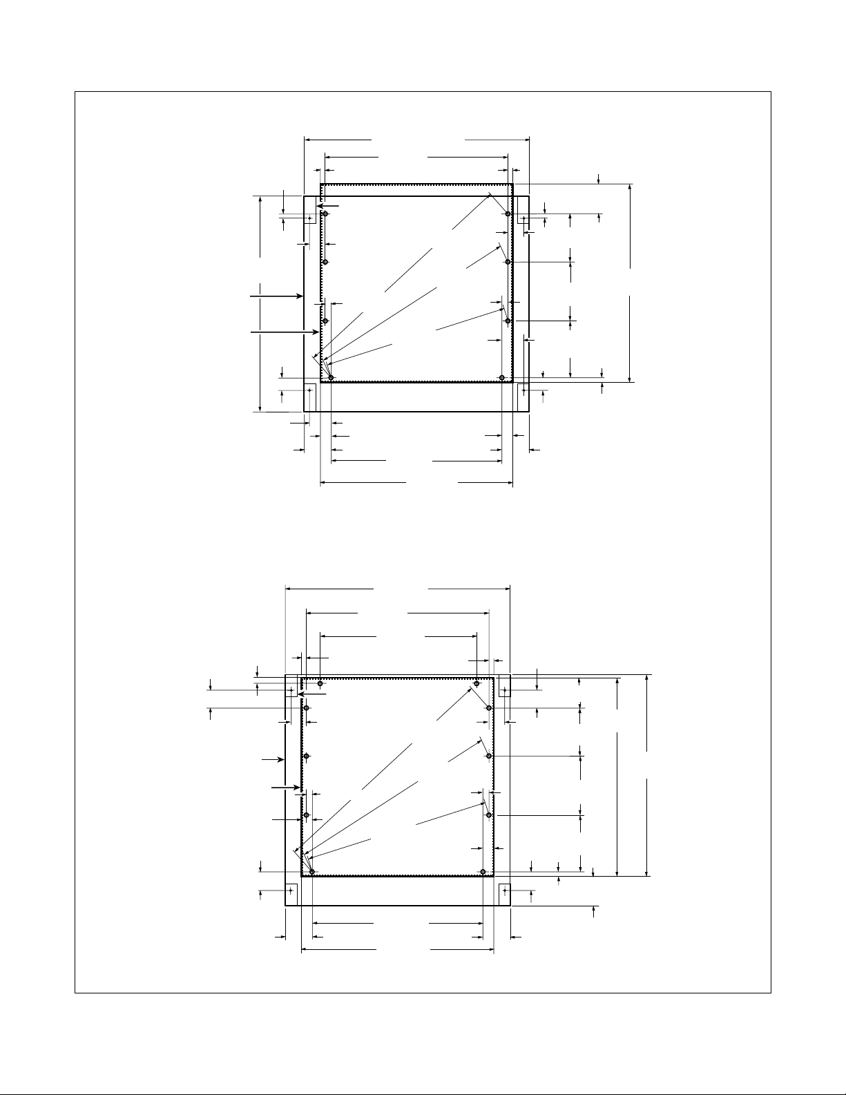
All UWPV machines use 5/16-18 x 6" bolts for
mounting the tank frame. Use the mounting bolt
layouts in Figure 2.
The threaded end of the bolts should extend 2 inches
above the surface of the floor.
Refer to Figure 1 for a typical installation of individual
mounting bolts for the water saving frame.
1
2
1 5/16" (8 mm)
2 6" (52 mm)
3 Frame
Figure 1
3
Q028I
F232122
9
Page 12
Installation
UW60PV
9/16" (14 mm)
(962 mm)
Outline of
Stand Boundary
Outline of
Frame Base
37-7/8"
(51 mm)
2"
41-5/16" (1049 mm)
34-1/8"
(867 mm)
3/4"
(19 mm)
Outline of
Stand Leg
2-9/16"
(65 mm)
1-1/4"
(32 mm)
34-19/32"
(879 mm)
(997 mm)
34-19/32"
(879 mm)
39-1/4"
(32 mm)
3-13/16"
(97 mm)
Front Edge of Machine
3/4"
(19 mm)
2-9/16"
(65 mm)
1-1/4"
9/16" (14 mm)
9"
(229 mm)
10-3/4"
(273 mm)
10-11/16"
(271 mm)
2"
(51 mm)
4-13/16"
(106 mm)
3/4"
(19 mm)
36"
(914 mm)
UW100PV
4-3/16"
(106 mm)
Outline of
Stand Boundary
Outline of
Frame Base
3-13/16"
(97 mm)
4-27/32"
(123 mm)
3/4"
(19 mm)
2-11/16"
(69 mm)
3"
(76 mm)
2-9/16"
(65 mm)
2"
(51 mm)
3/4"
(19 mm)
31-5/8"
(803 mm)
47-1/16"
(1195 mm)
39-5/8"
(1006 mm)
35-1/8"
(892 mm)
35-5/8"
(905 mm)
3/4"
(19 mm)
Outline of
Stand Leg
2-11/16"
(69 mm)
46-9/32"
(1176 mm)
2-1/4"
(57 mm)
(76 mm)
2-1/4"
(57 mm)
52-1/16"
(1323 mm)
39-25/32"
(1010 mm)
Front Edge of Machine
2"
(51 mm)
3"
4-27/32"
(123 mm)
4-3/16"
(106 mm)
6-3/4" (171 mm)
2-9/16"
(65 mm)
9"
(229 mm)
13-5/8"
(346 mm)
13-5/8"
(346 mm)
Q023I
Q023I
43-3/4"
(1111 mm)
44-3/16"
(1122 mm)
10
4-15/16"
(126 mm)
35-1/8"
(892 mm)
41-1/8"
(1045 mm)
Figure 2
3/4" (19 mm)
4-15/16"
(126 mm)
4-13/16"
(106 mm)
Q024I
Q024I
F232122
Page 13

Installation
Refer to the Water Saving System (WSS) General
Specifications in this section to determine if there is
adequate clearance through the door for the machine.
If there is not and the WSS needs to be removed, refer
to the section “Removing the Top Section”. If
clearance is sufficient, proceed as follows:
NOTE: Allow concrete to cure before beginning
installation.
1. Place the WSS next to the concrete foundation.
IMPORTANT: Move the WSS by lifting from the
frame only. Never move by lifting, pulling or
pushing the tanks.
2. Remove the carriage bolts holding the wooden
skid to the WSS frame side legs.
3. Place the WSS over the mounting bolts.
4. Level the frame top section and sides. Align with
the washer-extractor.
NOTE: No part of the washer-extractor and the
WSS should be touching. If the machine requires
elevating during bolt down then the WSS will
require the same amount.
Removing Top Section
If removing the top section is necessary due to
insufficient clearance, refer to Figure 3 and proceed as
follows:
1. Place the WSS next to the concrete foundation.
IMPORTANT: Move WSS by lifting from the
frame only. Never move by lifting, pulling or
pushing the tanks.
2. Secure top section with lifting equipment.
3. Remove the eight nuts and bolts from the top
section that fasten the frame sides to the top
section. Refer to Figure 3.
4. Secure both frame sides in place and lift top
section with lifting equipment.
5. Remove the frame sides from the wooden skid by
removing the carriage bolts holding them to the
skid. Remove frame support bar. Refer to Figure 3.
6. Place both frame sides over the mounting bolts
and replace frame support bar. Snugly screw down
the mounting nuts. Do not tighten nuts at this time.
5. Tighten mounting nuts and washers to secure
frame to floor.
F232122
11
Page 14
Installation
7. Carefully lower top section over frame sides.
Insert the eight top section bolts and four frame
support bar bolts. Fully tighten the corresponding
nuts with the corresponding bolts.
8. Level the frame top section and sides. Align with
the washer-extractor.
1
2
NOTE: No part of the washer-extractor and the
WSS should be touching. If the machine requires
elevating during bolt down then the WSS will
require the same amount.
9. Tighten mounting nuts and washers to secure
frame to floor.
Top Section RemovedTop Section Not Removed
1
4
2
5
6
7
3
Side ViewRear View
1 To p S ec t io n 5 To p S ec t io n Nu t s
2 Frame Support Bar 6 Frame Support Bar Nuts
3 Frame Sides 7 Frame Support Bar Bolts
4 Top Section Bolts
Figure 3
3
Q042I
12
F232122
Page 15
Installation
Instructions for Installation of
Pocket Hardmount Models (UWPV)
with Water Saving System
Read the following instructions thoroughly before
proceeding. The installer must have a comprehensive
understanding of the instructions before attempting
installation of the WSS. Refer to Water Saving Tank
Frame Foundation section for frame boltdown.
WARNING
Lock out the main power panel and lock out
the power supply to the control box before
attempting any service procedures.
SW007
IMPORTANT: Ensure that the machine is installed
on a level floor of sufficient strength and that the
recommended clearances for inspection and
maintenance are provided. Never allow the
inspection and maintenance space to be blocked.
Refer to the WSS Electrical Specifications for voltage
information.
Refer to the WSS General Specifications in this
section to determine if there is adequate clearance for
the machine. If there is not and the WSS needs to be
removed, refer to the previous section “Removing Top
Section”.
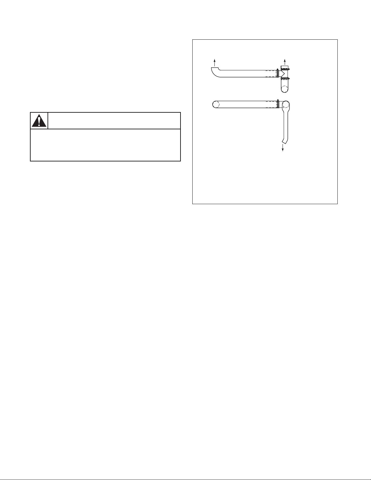
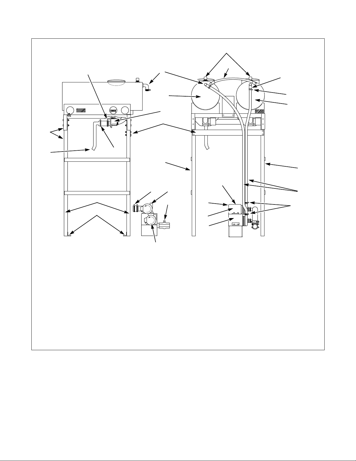
1. Connecting the WSS to washer-extractor:
Tank Drain Hose Assembly
1
NOTE: Right and Left are as Viewed from the Rear
1 To R ig h t Ta n k D r ain Va l ve
2 To Left Tank Drain Valve
3 To Washer-Extractor Shell Pipe
Figure 4
2
Top View
Front View
3
For 220V Machines:
a. For electrical hook-up, connect the control
signal cable to the “C1” (signal) quick
connect receptacle (top most plug on back of
washer-extractor control module). Connect
the power cable to the “C2” (power) quick
connect receptacle. Refer to Figure 7.
Q038I
NOTE: The tank drain hose assembly is packaged
inside washer-extractor basket.
a. Remove tank drain hose assembly from
packaging. Slide drain hose over tank drain
valves and washer-extractor shell pipe. Install
large hose clamps on drain valves and small
hose clamp on shell pipe and tighten. Refer to
Figures 4 and 5.
NOTE: Receptacles and plugs are keyed for proper
connection. For example, the control signal cable
will only fit in “C1”. Do not use excessive force
when connecting.
For 110V Machines:
a. Loosen the nut from the back of the PG9
strain relief found on the washer-extractor
control module rear. Thread 3-phase power
and green ground wires through the strain
relief and tighten the nut. Adjust extra wire
length through the strain relief, trimming off
extra length inside the control module leaving
enough to connect to input power terminal
block and ground.
b. Connect the 3-phase power wires to the input
power terminal block located inside the
washer-extractor control module.
F232122
13
Page 16

Installation
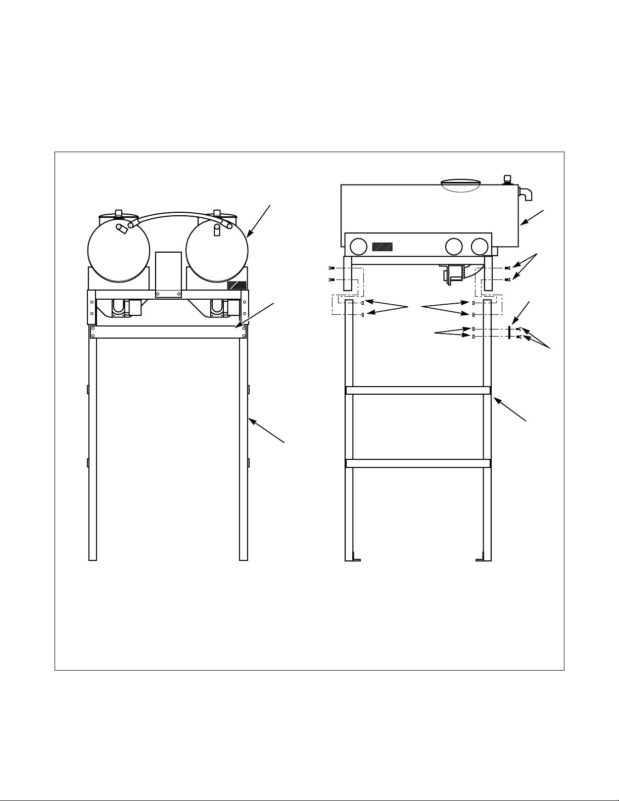
2. Installing the pump assembly (refer to Figure 5):
NOTE: The pump assembly is packaged inside
washer-extractor basket.
a. Remove the pump assembly from packaging
and place at the rear of the washer-extractor
resting flat on floor.
b. Route the two pump motor cable connections
to the WSS control housing (Figure 8). Slide
cable connectors in and twist to lock. Pump
cables and receptacles are marked “PA” and
“PB”. Refer to Figure 7.
c. Install large manifold hose clamp at the rear
of washer-extractor and tighten. Refer to
Figure 5.
d. Check ball valve for closed position. Before
operating machine, ball valve must be closed.
NOTE: Pump rotation must be counterclockwise
when pump is viewed from fan end or clockwise
when viewed from plastic pump head end.
Improper rotation will cause the pump to fail,
resulting in increased cycle time. Refer to rotation
arrow decal on pump and Figure 5. Rotation may
be corrected by exchanging two 3-phase power
wires on the load side of the respective contactor,
located in the remote-mounted WSS control
module.
3. Installing pump hose and vacuum vents:
NOTE: Pump hoses and vacuum vents are
packaged inside washer-extractor basket.
a. Remove pump hoses and four small hose
clamps from packaging.
b. Slide on the pump hose to the appropriate
pump (top pump to right tank, bottom pump
to left tank as viewed from rear) and tank
elbow at the rear of each tank. Refer to
Figure 5. Tighten the small hose clamps.
c. Apply Teflon tape to vacuum vent threads and
screw into top of each tank, tightening by
hand only.
d. Secure the two pump hoses and the two pump
motor cables with wire ties to frame side legs.
14
F232122
Page 17
Installation
4
20
19
1
2
2
3
6
5
7
11
8
18
8
8
10
10
17
16
9
11
12
13
9
21
14
Side View
15
Rear View
1 Large Hose Clamp 11 Ball Valve
2 Ta n k El bow 12 Pump Fan End
3 2" Tank Overflow 13 To p Pu m p
4 Vacuum Vent 14 Bottom Pump
5 Small Hose Clamp 15 Counterclockwise Pump Rotation
6 Left Tank 16 Carriage Bolts to Skid
7 Right Tank 17 Frame Side Legs
8 Frame Side 18 Tank Drain Hose Assembly
9 Pump Hoses 19 To Washer-Extractor Shell Pipe (Not Shown)
10 Pump Assembly 20 Frame
Figure 5
Q039I
F232122
15
Page 18
Installation
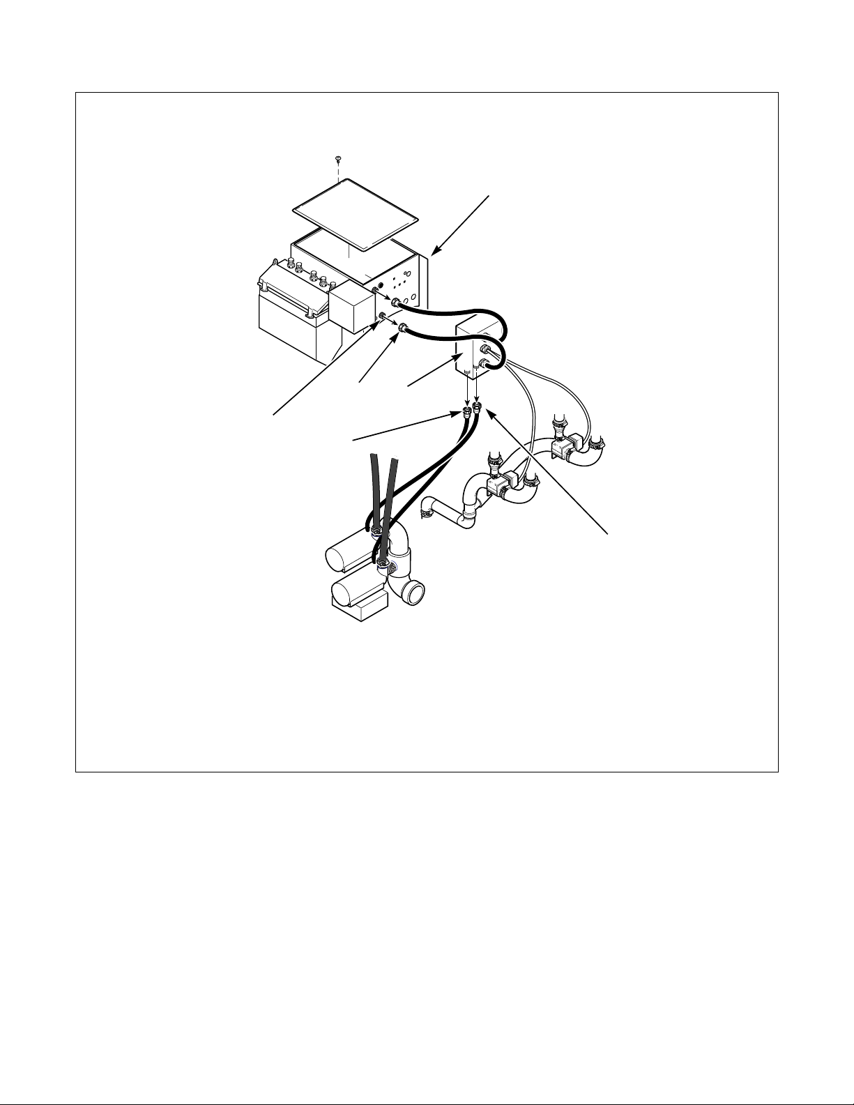
UW Integrated Water Saving System Machine Orientation
1
4
2
6
5
1 Washer-Extractor Control Module
2 Water Saving Control Housing
3 Quick Connect Receptacle for Tank “A” Pump Motor
4 Quick Connect Receptacle and Plug, C2 (Power)
5 Quick Connect Receptacle for Tank “B” Pump Motor
6 Quick Connect Receptacle and Plug, C1 (Signal)
Figure 6
3
Q043I
16
F232122
Page 19
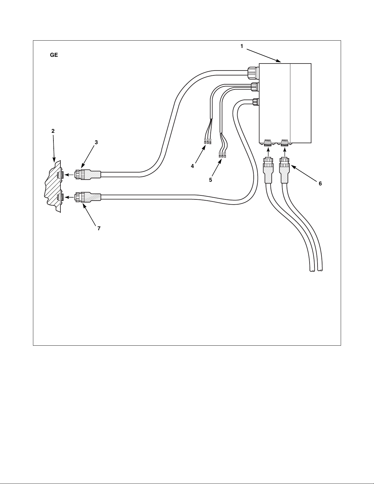
GENERALIZED SKETCH OF ELECTRICAL
CONNECTIONS WATER SAVER SYSTEM (220V)
REFER TO INSTRUCTIONS AND DRAWING
#634148 FOR DETAILS
2
3
Installation
1
4
7
1 Remote Mounted Control Module for Water Saving System
2 Rear of Control Module on Host Machine
3 C1 (Signal) Quick Connect Receptacle and Plug
4 Cable 133 to Tank “A” Drain Valve
5 Cable 132 to Tank “B” Drain Valve
6 Pumps “A” and “B” Quick Connect Receptacle and Plug
7 C2 (Power) Quick Connect Receptacle and Plug
Figure 7
5
6
Q041I
F232122
17
Page 20
Installation
Tank damage. Connections made to the
overflow must point downward from the
tank. Routing plumbing upward will damage
tanks.
CAUTION
Tank Overflows
Some tank overflows have external 2" PVC
connections. These connections may be plumbed to an
open trough or floor drain.
IMPORTANT: Connections made to the overflow
must provide adequate support for weight of pipe
and fittings.
Steam Heat Option
WARNING
Hot Surfaces. Will cause severe burns. Turn
steam off and allow steam pipes, connections
and components to cool before touching.
If the washer-extractor is equipped with the steam heat
option, additional pipe fittings are not required.
IMPORTANT: Do not route any steam fittings or
pipes near WSS tanks. Wrap fittings and pipe with
steam plumbing insulation.
18
F232122
Page 21

Installation
Instructions for Installation of
Cabinet Freestanding Models
(UFPV) with Water Saving System
Read the following instructions thoroughly before
proceeding. The installer must have a comprehensive
understanding of the instructions before attempting
installation of the WSS.
Refer to the WSS Electrical Specifications for voltage
information.
Refer to the WSS General Specifications to determine
if there is adequate clearance through the door for the
machine. If not, removal of the water tanks is
necessary.
1
1. Removing the water tanks (if necessary):
a. Remove the three cap plugs located near the
rear and one located near the front on each
side of the tanks. Refer to Figure 8.
b. Loosen the two hose clamps attached at the
bottom rear of each tank. Refer to Figure 8.
c. Loosen the hoses clamps attached to the
elbow at the rear of each tank and slide off the
long black hoses that run from the tanks.
Refer to Figure 9.
d. Loosen the hose clamp to the short black hose
between each tank and remove from only one
tank.
2
3
5
1 Water Tanks
2 Vacuum Vents
3 Water Saving Control Housing
4 Cap Plug
5 Hose Clamps Under Tank, Behind Plug
4
Q007I
Figure 8
F232122
19
Page 22

Installation
Be extremely careful when removing tanks.
To prevent damage, always place tanks on a
level surface with clean-out access facing
up.
CAUTION
e. Remove the four bolts from each tank located
behind cap plug at each corner. Refer to
Figure 9.
f. Lift tanks off the washer-extractor.
2. Removing the pump assembly:
a. Remove manifold hose clamps connecting the
pump manifold to the drain valve found at the
1
rear of the washer-extractor to the right of the
pump assembly. Refer to Figure 9.
b. Unscrew the two pump motor electrical quick
disconnects from the water saving control
housing located at the rear of the washerextractor.
c. Slide off the long black hoses that run from
the water tanks. Refer to Figure 9.
d. Remove pump assembly and place to the side.
3. Positioning and bolting down the washerextractor:
Refer to Mechanical Installation Section for
boltdown instructions.
2
5
3
4
1 Corner Tank Bolts (4 per Tank) 4 Pump Assembly
2 Hose Clamps on Elbows 5 Cap Plug
3 Manifold Hose Clamps
Q008I
Q008I
20
Figure 9
F232122
Page 23

Installation
4. Reassembling the pump assembly:
a. Replace pump assembly at the rear of the
washer-extractor, resting flat on the floor.
b. Secure the two pump motor electrical quick
disconnects to the water saving control
housing.
c. Replace manifold hose clamp at rear of
washer-extractor.
d. Check ball valve for closed position. Before
operating machine, ball valve must be closed.
NOTE: Pump rotation must be counterclockwise
when pump is viewed from fan end or clockwise
when viewed from plastic pump head end.
Improper rotation will cause the pump to fail
resulting in increased cycle time. Refer to rotation
arrow on pump in Figure 5. Rotation may be
corrected by exchanging two 3-phase power wires
at input power terminal block then recheck each
pump separately.
5. Replacing the water tanks:
a. Carefully replace the tanks on top of the
washer-extractor.
b. Replace the four bolts behind cap plug at each
corner of tanks.
c. Slide on short black hose to the large tank
elbow at the rear of the tank. Refer to Figure 9.
Tighten hose clamp.
d. Slide on long black hoses to the appropriate
tank elbow at the rear of each tank – right tank
to top pump, left tank to bottom pump.
Tighten hose clamps.
e. Tighten the three clamps underneath each
tank.
f. Replace the three cap plugs on each side of
the tanks.
6. Installing the tank vacuum vents:
a. Remove tank vacuum vents from packaging.
b. Apply Teflon tape to vacuum vent threads and
screw into top of each tank, tightening by
hand only.
Tank Overflows
Some tank overflows have external 2" PVC
connections. These connections may be plumbed to an
open trough or floor drain.
CAUTION
Tank damage. Connections made to the
overflow must point downward from the
tank. Routing plumbing upward will damage
tanks.
IMPORTANT: Connections made to the overflow
must provide adequate support for weight of pipe
and fittings.
F232122
21
Page 24

Notes
22
F232122
Page 25

Maintenance
Daily
Beginning of Day
Inspect water saving tanks and all associated plumbing
connections for leaks.
End of Day
Run drain tank cycle.
Weekly
Clean tanks by removing cap on top of tanks and flush
out with a hose. Sanitize as needed.
Monthly
Flush drain ball valve, opening fully, to purge any lint
or debris from pump manifold.
Check top section nuts on tank frame to ensure they
are tightened to the specified torque (220 in. lb.).
F232122
23
Page 26

Notes
24
F232122
Page 27

Removal from Service
Decommissioning
Check water tanks to make sure all water has been
emptied from both tanks.
F232122
25
Page 28

Notes
26
F232122
Page 29

Operation
LED Display
The following table lists the various displays for the
Manual Mode Control Feature
WSS functions are not manually controllable.
Water Saving System (WSS) and what they mean.
These displays are the same for both models and are
displayed in the left two display digits. The operator
should become familiar with these computer displays.
Display Interpretations
aL
aM
aH
bL
bM
bH
Da
Db
Fill machine from tank A to low level
Fill machine from tank A to medium level
Fill machine from tank A to high level
Fill machine from tank B to low level
Fill machine from tank B to medium level
Fill machine from tank B to high level
Drain machine to tank A
Drain machine to tank B
NOTE: The left tank is designated as tank A as seen from the front of the machine, the right tank is tank B.
Table 3
NOTE: To prevent water hotter than 160°F from
draining into the water saving tanks, an alarm will
sound and “DRTEMP” will be displayed. If the
STOP key is not pressed within two minutes, the
machine will automatically stop.
F232122
27
Page 30

Notes
28
F232122
Page 31

Programming
NOTE: The following programming information is
for both Cabinet Freestanding and Pocket
Hardmount models with the Water Saving System
(WSS). Use in conjunction with respective
operating/programming manuals.
When programming steps using the WSS, the
computer must be in the PROGRAM mode and ready
for the next step. The display will read “nncc”, where
“nn” represents step number and “cc” represents cycle
number.
Programming a Recovery Fill from
Water Saving Tank(s)
1. Press the Auxiliary key. The display will read
“A-nncc”.
2. Press key 6 to select a fill from tank A. The
display will read “a-nncc”. To select a fill from
tank B, press key 7 instead. The display will read
“b-nncc”.
3. Press the Low, Medium, or High key to select a
water level. The second digit of the display will
read either “L”, “M,” or “H”, respectively for a
low, medium, or high water level. For example, if
a low level fill from tank A is selected, the
display will read “aLnncc”.
4. Press the Enter key. The display will now read
“M---S”.
5. Enter the desired maximum fill time. To program
5 minutes, press key 5. The display will read
“5M-00S”.
Programming a Water Saving
Drain Step
1. Press the Drain key. The display will read “D-nncc”.
2. Press key 2 to drain tank A or key 3 to drain to
tank B. The display will read “Danncc” if tank A
is selected and “Dbnncc” if tank B is selected.
3. Press the Enter key. The display will read “M---S.”
4. Enter the desired time for the drain step. For
example, to enter a time of five minutes, press
key 5. The display will show “5M-00S.”
NOTE: If machine does not empty in this amount
of time, “EMTY”, will be displayed.
5. Press the Enter key and go to the next step in the
cycle or the PROGRAM mode may be exited.
NOTE: When programming a drain step, it is
necessary to specify which type of drain is desired,
because water saving features are available at all
times.
NOTE: The WE-6 computer will not permit draining
into a tank if the water temperature exceeds 160
degrees Fahrenheit. In that event, the display will
show “DRTEMP”, the WE-6 will turn off all outputs
(except applicable drain[s]) and will sound the buzzer.
This will continue for up to two minutes. If the
operator does not respond within two minutes the
WE-6 aborts the cycle. The operator can press the
START key to begin the drain step again, or press
the STOP key to end the cycle.
6. Once the desired time had been entered, press the
Enter key to go to the next step of the cycle or to
exit PROGRAM mode.
F232122
Programming Cycles
Refer to the Programming section in the Operation/
Programming manuals (P/N F232059 for UF models,
P/N F232089 for UW models) for preprogrammed cycles.
29
Page 32

Page 33

Sistema de ahorro
de agua
Suplemento de instrucciones de instalación,
mantenimiento, operación y programación
Refiérase a la identificación de modelos en la pagina 35
UW
Suplemento
UF
Guarde estas instrucciones para referencia futura.
(Si esta máquina cambia de dueño, este manual deberá ser entregado con la misma).
Q027I
Q027IE3A
Pieza No. F232122R3
Octubre 2000
Page 34

Page 35

Contenido
Introducción ........................................................................................ 35
Identificación de modelos..................................................................... 35
Instalación ........................................................................................... 37
Espacios libres ...................................................................................... 38
Cimientos para la máquina ................................................................... 40
Cimientos para la estructura de tanques del sistema de
ahorro de agua en modelos de lavadora extractora cilíndrica
de montaje permanente (UWPV) ................................................... 40
Instalación mecánica............................................................................. 41
Instalación de pernos de montaje para modelos de lavadora
extractora de gabinete autoestable (UFPV) con sistema de
ahorro de agua ................................................................................ 41
Instalación de pernos de montaje para modelos cilíndricos
de montaje permanente (UWPV) con sistema de ahorro de agua.. 41
Desmontaje de la sección superior................................................... 43
Instrucciones para instalación de modelos de lavadora
extractora cilíndrica de montaje permanente (UWPV) con
sistema de ahorro de agua .................................................................. 45
Agujeros de rebose de los tanques................................................... 50
Opción de calentamiento por vapor................................................. 50
Instrucciones para instalación de modelos de lavadora extractora de
gabinete autoestable (UFPV) con sistema de ahorro de agua ............ 51
Agujeros de rebose de los tanques................................................... 53
Mantenimiento .................................................................................... 55
Diariamente........................................................................................... 55
Al comienzo del día ......................................................................... 55
Al final del día ................................................................................. 55
Semanalmente....................................................................................... 55
Mensualmente....................................................................................... 55
Puesta fuera de servicio...................................................................... 57
Puesta fuera de servicio ........................................................................ 57
Operación ............................................................................................ 59
Pantalla de LED.................................................................................... 59
Función de control del modo manual ................................................... 59
Programación ...................................................................................... 61
Programación de un llenado de recuperación desde el(los)
tanque(s) del sistema de ahorro de agua............................................. 61
Programación de un paso de desagüe del sistema de ahorro de agua... 61
Ciclos preprogramados......................................................................... 61
© Copyright 2000, Alliance Laundry Systems LLC
Reservados todos los derechos. Ninguna sección del presente manual puede ser reproducida o transmitida en forma
alguna o a través de ningún medio, sin el expreso consentimiento por escrito del editor
.
F232122 (SP)
33
Page 36

Notas
34
F232122 (SP)
Page 37

Introducción
Identificación de modelos
La información contenida en este manual es aplicable
a los siguientes modelos:
UW 60 PV
UW 100 PV
UF 35 PV
UF 50 PV
UF 85 PV
F232122 (SP)
35
Page 38

Notas
36
F232122 (SP)
Page 39

Instalación
Este manual está diseñado como un suplemento para la
instalación, mantenimiento, operación y programación
de las lavadoras extractoras modelos PV de gabinete
autoestable y cilíndrica de montaje permanente,
equipadas con el sistema de ahorro de agua (WSS).
Especificaciones generales de modelos con sistema de ahorro de agua
Cilíndrico de montaje
Modelos
Anchura general, mm (plg)
Altura general, mm (plg)
Profundidad general, mm (plg)
Peso neto, kg (lb)
Peso de transporte
doméstico, kg (lb)
Volumen de transporte
doméstico, m
3
(pies3)
Peso de transporte de
exportación, kg (lb)
Volumen de de exportación,
3
m
(pies3)
1053 (41 7/16) 1195 (47 1/16) 889 (35) 990,6 (39) 1181,1 (46 1/2)
1568 (61 3/4) 1861 (73 1/4) 1392 (54) 1449 (56,85) 1670 (65 3/4)
657,7 (1450) 821 (1810) 595,1 (1312) 771,1 (1700) 1406,1 (3100)
707,6 (1560) 877,7 (1935) 639,6 (1410) 816,5 (1800) 1474,2 (3250)
726 (1600) 967 (2130) 681 (1500) 863 (1900) 1521 (3350)
permanente
UW60PV UW100PV UF35PV UF50PV UF85PV
Dimensiones generales
2311 (91) 2429 (95 5/8) 2070 (81 1/2) 2159 (85) 2426 (95 1/2)
Información de peso y transporte
5,8 (207) 6,0 (212) 3,88 (137) 4,05 (143) 4,04 (201)
6,5 (229) 6,7 (235) 3,88 (137) 4,05 (143) 5,69 (201)
Este manual debe usarse junto con la información que
aparece en los manuales con números de parte
F232084, F232089, F232058 y F232059 (que se
suministran con la lavadora extractora).
De gabinete autoestable
Especificaciones eléctricas para modelos con sistema de ahorro de agua*
Designación del voltaje Estándar Calor eléctrico
Modelo Código Voltaje Ciclo Fase Cable
Amperios
de plena
carga
Disyuntor
Galga
americana
para
alambres
mm
Amperios
2
de plena
carga
Disyuntor
Galga
americana
para
alambres
mm
N 440-480 50-60 3 3 6 15 14 3x2,5 33 40 8 3x10
60
WSS
P 380-415 50-60 3 3 6 15 14 3x2,5 29 40 8 3x10
Q 200-240 50-60 3 3 12 15 14 3x2,5 66 80 3 3x25
N 440-480 50-60 3 3 6 15 14 3x2,5 32 35 8 3x10
35
WSS
P 380-415 50-60 3 3 6 15 14 3x2,5 32 35 8 3x10
Q 200-240 50-60 3 3 12 15 14 3x2,5 50 50 8 3x10
N 440-480 50-60 3 3 6 15 14 3x2,5 43 50 8 3x10
50
WSS
P 380-415 50-60 3 3 6 15 14 3x2,5 43 50 8 3x10
Q 200-240 50-60 3 3 12 15 14 3x2,5 76 80 4 3x25
NOTA: Los tamaños de los cables que aparecen son para el conductor de cobre, THHN, de 90° para el artículo
NEC 310.
*La información de voltaje para los modelos *UW80PVWSS es igual a la de los modelos estándares UW80PV.
2
F232122 (SP)
37
Page 40

Instalación
Espacios libres
UWPV cilíndrica de montaje permanente con sistema de ahorro de agua
Dimensiones de la máquina*
Dimensiones
60 100
plg mm plg mm
A
B
C
D
41-7/16 1052,5 47-1/16 1195,4
91 2311 95-5/8 2428,9
61-3/4 1568 73-1/4 1861
15-3/4 400 15-3/4 400
* Deje una separación de por lo menos 610 mm (24 plg) por la parte trasera y 460 mm (18 plg) por los lados, para fines de
mantenimiento, inspección y ajuste. Deje por lo menos 460 mm (18 plg) entre una máquina y otra en instalaciones de
múltiples unidades.
C
A
38
B
D
Q020I
Q020I
F232122 (SP)
Page 41

Instalación
UFPV de gabinete autoajustable con sistema de ahorro de agua
Dimensiones de la máquina*
35 50 85
Dimensiones
mm plg mm plg mm plg
A
B
C
D
889 35 990,6 39 1181,1 46-1/2
2070 81-1/2 2159 85 2426 95-1/2
1448 57 1537 60-1/2 1727 68
400 15-3/4 400 15-3/4 400 15-3/4
* Deje una separación de por lo menos 610 mm (24 plg) por la parte trasera y 460 mm (18 plg) por los lados, para fines de
mantenimiento, inspección y ajuste. Deje por lo menos 460 mm (18 plg) entre una máquina y otra en instalaciones de
múltiples unidades.
A
C
B
D
Q002I
F232122 (SP)
39
Page 42

Instalación
Cimientos para la máquina
Para obtener la información relacionada con los
cimientos, tanto para el modelo UWPV como para el
modelo UFPV, consulte la sección correspondiente de
los manuales de instalación/mantenimiento
respectivos.
Para obtener la información sobre los modelos UFPV
con el sistema de ahorro de agua, consulte en la Tabl a 1
los datos de carga total sobre el piso.
Datos de carga sobre el piso de la lavadora
extractora UFPV de gabinete autoestable
35 50 85
Carga estática sobre el
piso, kN (lb)
Presión estática
2
kN-m
(lb-pie2)
Cimientos para la estructura de tanques
del sistema de ahorro de agua en
modelos de lavadora extractora cilíndrica
de montaje permanente (UWPV)
9,755
(2193)
11,07
(231)
Tabla 1
11,899
(2675)
11,45
(239)
22,472
(5052)
15,00
(313)
IMPORTANTE: Asegúrese de que la estructura de
los tanques quede instalada sobre un piso nivelado
con suficiente resistencia y de que se dejen los
espacios libres recomendados para inspección y
mantenimiento. Nunca permita que dichos espacios
queden bloqueados.
La estructura de los tanques debe ser anclada a una
superficie uniforme y nivelada, de tal forma que las
cuatro patas queden apoyadas y descansen sobre toda
la superficie de montaje.
Si la instalación de la lavadora extractora incluye el
WSS, la base elevada deberá diseñarse para aceptar
una anchura adicional de 10 cm (4 plg) pjor cada lado
de la lavadora extractora y corregir así la alineación.
En la Tabl a 2 se presenta la carga de la lavadora
extractora, de los tanques y de la estructura sobre el
piso o los cimientos.
Datos de carga sobre el piso de la lavadora
extractora UWPV cilíndrica de montaje
Carga estática sobre
el piso, kN (lb)
permanente
60 100
11,7
(2617)
19,3
(4341)
Unos cimientos apropiados son absolutamente
necesarios para todas las lavadoras extractoras UWPV
con sistemas de ahorro de agua debido al peso del agua
a alturas elevadas.
NOTA: No realice la instalación sobre pisos de
madera, en pisos superiores o sobre sótanos. La
instalación debe ser hecha sobre una losa rasante
de hormigón, o similar.
Presión estática por pata
kN-m
2
(lb-pie2)
Tabla 2
10,9
(227)
13,0
(271)
40
F232122 (SP)
Page 43

Instalación
Instalación mecánica
Instalación de pernos de montaje para
modelos de lavadora extractora de
gabinete autoestable (UFPV) con sistema
de ahorro de agua
Consulte el manual de instalación/mantenimiento
(N/P F232059) para obtener información sobre la
instalación de los pernos de montaje en los modelos
UFPV.
Instalación de pernos de montaje para
modelos cilíndricos de montaje
permanente (UWPV) con sistema de
ahorro de agua
NOTA: La estructura del WSS deberá quedar
fijada permanentemente al piso.
Todas las máquinas UWPV usan pernos de
5/16-18 x 6 plg para el montaje de la estructura de
tanques. Siga el esquema de montaje de los pernos que
aparece en la Figura 2.
En la Figura 1 se indica la instalación típica de los
pernos de montaje individuales en la estructura del
sistema de ahorro de agua.
1
2
1 8 mm (5/16")
2 52 mm (6")
3 Estructura
Figura 1
3
Q028I
El extremo con rosca de los pernos debe sobresalir
5 cm (2 plg) sobre la superficie del suelo.
F232122 (SP)
41
Page 44

Instalación
plg
Perfil del área ocupada
por la unidad
Perfil de la base
de la estructura
UW60PV
14 mm (9/16 plg)
962 mm
(37-7/8 plg)
51 mm
(2 plg)
97 mm
(3-13/16 plg)
123 mm
(4-27/32 plg)
1049 mm (41-5/16 plg)
867 mm
19 mm
(3/4plg)
(34-1/8 plg)
Perfil de la pata
de soporte
65 mm
(2-9/16 plg)
32 mm
(1-1/4 plg)
(34-19/32 plg)
879 mm
(34-19/32 plg)
Borde delantero
de la máquina
51 mm
(2 plg)
803 mm
(31-5/8 plg)
879 mm
997 mm
(39-1/4 plg)
905 mm
(35-5/8 plg)
19 mm
(3/4 plg)
65 mm
(2-9/16 plg)
32 mm
(1-1/4 plg)
97 mm
(3-13/16 plg)
51 mm
(2 plg)
106 mm
(4-13/16 plg)
14 mm (9/16 plg)
229 mm
(9 plg)
273 mm
(10-3/4 plg)
271 mm
(10-11/16 plg)
51 mm
(2 plg)
123 mm
(4-27/32 plg)
19 mm
(3/4 plg)
914 mm
(36 plg)
Q023I
UW100PV
19 mm
106 mm
(4-3/16 plg)
(3/4 plg)
69 mm
(2-11/16 plg)
Perfil del área
ocupada por la unidad
Perfil de la base de
la estructura
76 mm
(3 plg)
65 mm
(2-9/16 plg)
126 mm
(4-15/16 plg)
1195 mm
(47-1/16 plg)
1006 mm
(39-5/8 plg)
892 mm
19 mm
(3/4 plg)
(35-1/8 plg)
Perfil de la pata
de soporte
1323 mm
(52-1/16 plg)
57 mm
(2-1/4 plg)
1010 mm
(39-25/32 plg)
Borde delantero
de la máquina
892 mm
(35-1/8 plg)
1045 mm
(41-1/8 plg)
19 mm
(3/4 plg)
69 mm
(2-11/16 plg)
1176 mm
(46-9/32 plg)
57 mm
(2-1/4 plg)
76 mm
(3 plg)
106 mm
(4-3/16 plg)
171 mm (6-3/4 plg)
229 mm (9 plg)
65 mm
(2-9/16 plg)
19 mm (3/4 plg)
126 mm
(4-15/16 plg)
346 mm
(13-5/8 plg)
346 mm
(13-5/8 plg)
106 mm
(4-13/16 plg)
1111 mm
(43-3/4 plg)
(44-3/16 plg)
Q023I
1122 mm
Q024I
Q024I
42
Figura 2
F232122 (SP)
Page 45

Instalación
Consulte en esta sección las especificaciones generales
del sistema de ahorro de agua (WSS) para determinar
si hay una separación adecuada alrededor de la puerta
de la máquina. Si no la hay, y el WSS necesita ser
retirado, consulte la sección “Desmontaje de la
sección superior”. Si la separación es suficiente,
continúe como se indica a continuación:
NOTA: Espere a que el concreto (hormigón) se cure
antes de comenzar la instalación.
1. Coloque el WSS al lado del cimiento de
concreto.
IMPORTANTE: Mueva el WSS levantándolo por
la estructura únicamente. Nunca mueva el WSS
levantando, empujando o tirando de los tanques.
2. Saque los pernos de máquina sujetando la
plataforma de madera a las patas laterales de la
estructura del WSS.
3. Coloque el WSS sobre los pernos de montaje.
4. Nivele las secciones superior y laterales de la
estructura. Alinéela con la lavadora extractora.
Desmontaje de la sección superior
Si es necesario desmontar la sección superior debido a
que no hay espacio suficiente, consulte la Figura 3 y
proceda como se indica a continuación:
1. Coloque el WSS al lado del cimiento de
concreto.
IMPORTANTE: Mueva el WSS levantándolo por
la estructura únicamente. Nunca mueva el WSS
levantando, empujando o tirando de los tanques.
2. Sujete la sección superior con el equipo de izado.
3. Saque de la sección superior los ocho pernos y
tuercas que sujetan los lados de la estructura a la
parte superior. Consulte la Figura 3.
4. Asegure en su lugar ambos lados de la estructura
y levante la sección superior con el equipo de
izado.
5. Saque de la plataforma de madera los lados de la
estructura sacando para ello los pernos que los
mantienen unidos a la plataforma. Saque la barra
de soporte de la estructura. Consulte la Figura 3.
NOTA: La lavadora extractora y el WSS no deben
hacer contacto en ningún punto. Si es necesario
elevar la máquina para apretar los pernos, el WSS
deberá elevarse también a una altura equivalente.
5. Apriete las tuercas y arandelas de montaje para
asegurar la estructura al piso.
6. Coloque ambos lados de la estructura sobre los
pernos de montaje y vuelva a colocar la barra de
soporte de la estructura. Enrosque las tuercas de
montaje hasta que las piezas queden unidas, pero
lo apriete las tuercas todavía.
F232122 (SP)
43
Page 46

Instalación
7. Baje con cuidado la sección superior sobre los
lados de la estructura. Inserte los ocho pernos de
la sección superior, y los cuatro pernos de la
barra de soporte de la estructura. Coloque las
tuercas correspondientes y apriételas bien.
8. Nivele la sección superior y los lados de la
estructura. Alinéelos con la lavadora extractora.
1
2
NOTA: La lavadora extractora y el WSS no deben
hacer contacto en ningún punto. Si es necesario
elevar la máquina para apretar los pernos, el WSS
deberá elevarse también a una altura equivalente.
9. Apriete las tuercas y arandelas de montaje para
asegurar la estructura al piso.
Con la sección superior desmontadaCon la sección superior instalada
1
4
2
5
6
7
3
3
Vista lateralVista posterior
Q042I
1 Sección superior 5 Tuercas de la sección superior
2 Barra de soporte de la estructura 6 Tuercas de la barra de soporte de la estructura
3 Lados de la estructura 7 Pernos de la barra de soporte de la estructura
4 Pernos de la sección superior
44
Figura 3
F232122 (SP)
Page 47

Instalación
Cierre con llave el panel de alimentación
principal y en la fuente de corriente
eléctrica que llega a la caja de control antes
de realizar cualquiera de los
procedimientos de servicio.
ADVERTENCIA
SW007
Instrucciones para instalación de
modelos de lavadora extractora
cilíndrica de montaje permanente
(UWPV) con sistema de ahorro de
agua
Lea detenidamente las instrucciones siguientes antes
de proceder. El instalador deberá estar bien
familiarizado con las instrucciones antes de intentar la
instalación del WSS. Consulte la sección “Cimientos
para la estructura de tanques del sistema de ahorro de
agua” en lo relacionado con el apriete de los pernos.
IMPORTANTE: Asegúrese de que la máquina sea
instalada sobre un piso nivelado con la suficiente
resistencia y de que se mantengan los espacios
libres necesarios para inspección y mantenimiento.
Nunca permita que el espacio para inspección y
mantenimiento quede bloqueado.
Consulte las especificaciones generales del WSS en
esta sección para determinar si hay espacio suficiente
para la máquina. Si no lo hay, y es necesario retirar el
WSS, consulte la sección “Desmontaje de la sección
posterior”.
Consulte las Especificaciones eléctricas para modelos
con sistema de ahorro de agua (WSS) para obtener
información sobre el voltaje.
1. Conexión del WSS a la lavadora extractora:
NOTA: El conjunto de mangueras de desagüe viene
en un paquete dentro del cesto de la lavadora
extractora.
a. Saque del paquete el conjunto de mangueras
de desagüe del tanque. Coloque la manguera
de desagüe en las válvulas de desagüe del
tanque y en la tubería con revestimiento de la
lavadora extractora. Instale las abrazaderas de
manguera grandes en las válvulas de desagüe
y la abrazadera de manguera pequeña en la
tubería con revestimiento, y apriételas.
Consulte las Figuras 4 y 5.
F232122 (SP)
Montaje de manguera de desagüe de los tanques
1
NOTA: Las posiciones derecha e izquierda están
referidas a un observador ubicado en la parte
posterior de la máquina.
1 A la válvula de desagüe del tanque derecho
2 A la válvula de desagüe del tanque izquierdo
3 Al tubo del cilindro de la lavadora extractora
Figura 4
2
Vista
superior
Vista
frontal
3
Q038I
Para máquinas de 220V:
a. Para realizar una conexión eléctrica, conecte
el cable de señal de control al receptáculo de
desconexión rápida “C1” (señal) (la clavija
que se encuentra más arriba en la parte
posterior del módulo de control de la lavadora
extractora). Conecte el cable de alimentación
al receptáculo de desconexión rápida “C2”
(alimentación). Consulte la Figura 7.
NOTA: Los receptáculos y clavijas están marcados
para realizar una conexión correcta. Por ejemplo,
el cable de señal de control sólo encaja en “C1”. No
aplique demasiada fuerza al conectar.
Para máquinas de 110V:
a. Afloje la tuerca de la parte trasera del
protector contra tirones PG9, ubicado en la
parte posterior del módelo de control de la
lavadora extractora. Consulte la Figura 8.
Haga pasar los cables de alimentación
trifásica y el cable verde de tierra a través del
protector contra tirones, recogiendo el exceso
de cable dentro del módulo de control, y
dejando una longitud suficiente para la
conexión al boque de terminales de
alimentación de entrada y de tierra.
b. Conecte los cables de alimentación trifásica al
bloque de terminales de entrada de
alimentación, ubicado dentro del modulo de
control de la lavadora extractora.
45
Page 48

Instalación
2. Instalación del conjunto de bombas (consulte la
Figura 5):
NOTA: El conjunto de bombas viene en un paquete
dentro del cesto de la lavadora extractora.
a. Saque el conjunto de bombas del paquete y
colóquelo por la parte posterior de la lavadora
extractora, descansando en posición
horizontal sobre el suelo.
b. Encamine los dos cables de conexión del
motor al alojamiento de control del WSS (ver
Figura 8). Deslice los conectores hacia dentro
y enrósquelos hasta que queden bloqueados.
Los receptáculos y cables de bomba están
marcados “PA” y “PB”. Consulte la Figura 7.
c. Instale la abrazadera grande de la manguera
del distribuidor ubicada en la parte posterior
de la lavadora extractora y apriétela. Consulte
la Figura 5.
d. Compruebe que la válvula de bola está en la
posición cerrada. Antes de hacer funcionar la
máquina, la válvula de bola deberá estar
cerrada.
3. Instalación de la manguera de la bomba y las
bocas de ventilación:
NOTA: Las mangueras de bomba y las bocas de
ventilación vienen en un paquete dentro del cesto
de la lavadora extractora.
a. Saque del paquete las mangueras de las
bombas y cuatro abrazaderas de manguera
pequeñas.
b. Coloque la manguera en la bomba apropiada
(bomba superior al tanque derecho, bomba
inferior al tanque izquierdo, vistos desde la
parte posterior) y el codo del tanque a la parte
posterior de cada tanque. Consulte la Figura 5.
Apriete las abrazaderas de manguera pequeñas.
c. Coloque cinta de teflón a las roscas de las
bocas de ventilación y enrosque encima de
cada tanque; apriete con la mano solamente.
d. Asegure a las patas de la estructura las dos
mangueras de bomba y los dos cables de
motor de bomba con abrazaderas para cable.
NOTA: La bomba deberá girar en sentido
contrario al de las agujas del reloj cuando es vista
desde el extremo del ventilador, o en el sentido de
las agujas del reloj cuando es vista desde el extremo
del cabezal plástico de la bomba. La rotación
invertida hará fallar la bomba, lo cual alargaría el
tiempo de ciclo. Observe el rótulo con la flecha
indicadora del sentido de rotación sobre la bomba y
en la Figura 5. Para corregir el sentido de rotación,
intercambie dos de los cables de alimentación
trifásica en el lado de la carga del contactor
respectivo, ubicado en el módulo de control de
ahorro de agua (WSS) montado a distancia.
46
F232122 (SP)
Page 49

Instalación
4
20
19
1
2
2
3
6
5
7
11
8
18
8
8
10
10
17
16
9
11
12
13
9
21
14
Vista Lateral
15
Vista Posterior
1 Abrazadera de manguera larga 13 Bomba superior
2 Codo de tanque 14 Bomba inferior
3 Agujero de desagüe de tanque de 2 plg 15 Rotación de la bomba en sentido antihorario
4 Agujeros de ventilación de vacío 16 Pernos de máquina para sujeción de la
5 Abrazadera de manguera pequeña
plataforma de transporte
6 Tanque izquierdo 17 Patas laterales de la estructura
7 Tanque derecho 18 Conjunto de mangueras de desagüe de los
8 Lados de la estructura
tanques
9 Mangueras de bomba 19 Al tubo del cilindro de la lavadora extractora
10 Conjunto de bombas
(no mostrado)
11 Válvula de bola 20 Estructura
12 Extremo de ventilador de bomba
Figura 5
Q039I
F232122 (SP)
47
Page 50

Instalación
Orientación de la máquina con sistema de ahorro de agua integrado UW
1
4
2
6
5
1 Módulo de control de la lavadora extractora
2 Alojamiento del control de ahorro de agua
3 Receptáculo de conexión rápida para el motor de la bomba del Tanque “A”
4 Receptáculo y clavija de conexión rápida, C2 (Alimentación)
5 Receptáculo de conexión rápida para el motor de la bomba del Tanque “B”
6 Receptáculo y clavija de conexión rápida, C1 (Señal)
Figura 6
3
Q043I
48
F232122 (SP)
Page 51

ILUSTRACION GENERALIZADA DE CONEXIONES
ELECTRICAS DEL SISTEMA DE AHORRO DE AGUA (220V).
CONSULTE LAS INSTRUCCIONES Y LA GRAFICA #634148
PARA MAYORES DETALLES.
2
3
4
Instalación
1
5
7
1 Módulo de control de ahorro de agua montado a distancia
2 Parte posterior del módulo de control en la máquina principal
3 Receptáculo y clavija de conexión rápida C1 (Señal)
4 Cable 133 a la válvula de desagüe del Tanque “A”
5 Cable 132 a la válvula de desagüe del Tanque “B”
6 Receptáculo y clavija de conexión rápida de las bombas “A” y “B”
7 Receptáculo y clavija de conexión rápida C2 (Alimentación)
Figura 7
6
Q041I
F232122 (SP)
49
Page 52

Instalación
Daño al tanque. Las conexiones hechas a la
salida de desborde deberán apuntar hacia
abajo del tanque. El tendido de tubería
hacia arriba causará daño a los tanques.
PRECAUCIÓN
Agujeros de rebose de los tanques
Algunos agujeros de rebose tienen conexiones
externas de PVC de 2 plg. Estas conexiones pueden
desaguarse en una batea o desagüe en el piso.
IMPORTANTE: Las conexiones hechas a la salida
de desborde deberán proporcionar un soporte
adecuado proporcional al peso de la tubería y los
conectores.
Opción de calentamiento por vapor
ADVERTENCIA
Superficies calientes. Causará quemaduras
severas. Cierre la fuente de vapor y espere
a que se enfríen las tuberías de vapor,
conexiones y demás componentes antes de
tocarlos.
Si la lavadora extractora está equipada con la opción
de calentamiento por vapor, no es necesario usar
piezas de conexión de tuberías adicionales.
IMPORTANTE: No tienda conectores ni tuberías
cerca de los tanques del sistema de ahorro de agua.
Envuelva los conectores y las tuberías con aislante
de vapor para tuberías.
50
F232122 (SP)
Page 53

Instalación
Instrucciones para instalación de
modelos de lavadora extractora de
gabinete autoestable (UFPV) con
sistema de ahorro de agua
Lea detenidamente las instrucciones siguientes antes
de proceder. El instalador deberá estar bien
familiarizado con las instrucciones antes de intentar la
instalación del WSS.
Consulte las Especificaciones eléctricas para modelos
con sistema de ahorro de agua (WSS) para obtener
información sobre el voltaje.
Consulte las Especificaciones generales del WSS para
determinar si hay una separación adecuada alrededor
de la puerta de la máquina. Si no la hay, será necesario
desmontar los tanques de agua.
1. Desmontaje de los tanques de agua (si es
necesario):
1
a. Saque los tres tapones de sombrerete (dos de
ellos ubicados cerca de la parte posterior, y el
otro ubicado cerca de la parte frontal), por
cada lado de los tanques. Consulte la
Figura 8.
b. Afloje las dos abrazaderas de manguera
acopladas por la parte inferior trasera de cada
tanque. Consulte la Figura 8.
c. Afloje las dos abrazaderas de manguera
acopladas al codo que está ubicado en la parte
posterior de cada tanque, y saque las
mangueras negras largas conectadas a los
tanques. Consulte la Figura 9.
d. Afloje la abrazadera de manguera acoplada a
la manguera negra corta que interconecta los
tanques y desconecte solamente de uno de los
tanques.
4
5
1 Tanques de agua
2 Agujeros de ventilación de vacío
3 Alojamiento del control de ahorro de agua
4 Ta pón de sombrerete
5 Abrazaderas de manguera debajo del tanque, detrás del tapón
2
3
Q007I
F232122 (SP)
Figura 8
51
Page 54

Instalación
Tenga mucho cuidado al retirar los tanques.
Para evitar daños, coloque siempre los
tanques sobre una superficie nivelada con
acceso para limpieza por encima.
PRECAUCIÓN
e. Saque los cuatro pernos de cada tanque,
localizados detrás del tapón de sombrerete en
cada esquina. Consulte la Figura 9.
f. Levante los tanques de la lavadora extractora.
2. Desmontaje del conjunto de bombas:
a. Saque las abrazaderas de la manguera del
distribuidor que conecta el distribuidor de
bomba con la válvula de desagüe localizada
en la parte posterior de la lavadora extractora,
a la derecha del conjunto de bombas. Consulte
la Figura 9.
b. Desenrosque del alojamiento de control del
sistema de ahorro de agua (localizado en la
parte posterior de la lavadora extractora) las
dos piezas de desconexión eléctrica rápida de
los motores de bomba.
c. Saque las dos mangueras negras largas
conectadas a los tanques de agua. Consulte la
Figura 9.
d. Saque el conjunto de bombas y colóquelo a un
lado.
3. Ubicación de la lavadora extractora en su
posición definitiva y fijación mediante pernos:
Consulte las instrucciones de fijación mediante
pernos en la sección Instalación mecánica.
1
2
5
3
4
1 Pernos de esquina de los tanques (4 por tanque) 4 Conjunto de bombas
2 Abrazaderas de manguera en codos 5 Ta p ón de sombrerete
3 Abrazaderas de manguera en distribuidor
Q008I
Q008I
52
Figura 9
F232122 (SP)
Page 55

Instalación
4. Montaje del conjunto de bombas:
a. Reinstale el conjunto de bombas en la parte
posterior de la lavadora extractora, en
posición horizontal sobre el piso.
b. Asegure las dos piezas de conexión eléctrica
de los motores de bomba al alojamiento del
control del sistema de ahorro de agua.
c. Coloque la abrazadera de la manguera del
distribuidor en la parte posterior de la
lavadora extractora.
d. Compruebe que la válvula de bola está en la
posición cerrada. Antes de hacer funcionar la
máquina, la válvula de bola deberá estar
cerrada.
NOTA: La bomba deberá girar en sentido
contrario al de las agujas del reloj cuando es vista
desde el extremo del ventilador, o en el sentido de
las agujas del reloj cuando es vista desde el extremo
del cabezal plástico de la bomba. La rotación
invertida hará fallar la bomba, lo cual alargaría el
tiempo de ciclo. Observe el rótulo con la flecha
indicadora del sentido de rotación sobre la bomba y
en la Figura 5. Para corregir el sentido de rotación,
intercambie dos de los cables de alimentación
trifásica en el bloque de terminales de alimentación
de entrada, y compruebe cada bomba por
separado.
5. Reinstalación de los tanques de agua:
a. Coloque con cuidado los tanques encima de la
lavadora extractora.
b. Coloque los cuatro pernos detrás de los
tapones de sombreretes ubicados en cada una
de las esquinas de los tanques.
d. Coloque las mangueras negras largas en los
codos correspondientes, ubicados por la parte
trasera de cada tanque: el tanque de la derecha
con la bomba superior, y el tanque de la
izquierda con la bomba inferior. Apriete las
abrazaderas de las mangueras.
e. Apriete las tres abrazaderas debajo de cada
tanque.
f. Coloque los tres tapones de sombrerete por
cada lado de los tanques.
6. Instalación de las bocas de ventilación de
tanques:
a. Saque las bocas de ventilación del paquete.
b. Coloque cinta de teflón a las roscas de las
aberturas de ventilación y enrosque encima de
cada tanque; apriete con la mano solamente.
Agujeros de rebose de los tanques
Algunos agujeros de rebose tienen conexiones
externas de PVC de 2 plg. Estas conexiones pueden
desaguarse en una batea o desagüe en el piso.
PRECAUCIÓN
Daño al tanque. Las conexiones hechas a la
salida de desborde deberán apuntar hacia
abajo del tanque. El tendido de tubería
hacia arriba causará daño a los tanques.
IMPORTANTE: Las conexiones hechas a la salida
de desborde deberán proporcionar un soporte
adecuado proporcional al peso de la tubería y los
conectores.
c. Coloque la manguera negra corta en el codo
ubicado por la parte trasera del tanque grande.
Consulte la Figura 9. Apriete la abrazadera de
la manguera.
F232122 (SP)
53
Page 56

Notas
54
F232122 (SP)
Page 57

Mantenimiento
Diariamente
Al comienzo del día
Inspeccione que no haya fugas en los tanques del
sistema de ahorro de agua ni en ninguna de las
conexiones asociadas con los mismos.
Al final del día
Active el ciclo de desagüe de los tanques.
Semanalmente
Limpie los tanques; para ello, saque los tapones
ubicados encima de los tanques y aplique abundante
agua con una manguera. Desinfecte si es necesario.
Mensualmente
Enjuague con abundante agua la válvula de bola de
desagüe; para ello, ábrala completamente a fin de
purgar todas las pelusas y partículas que haya en el
distribuidor de bombas.
Compruebe que las tuercas de la sección superior de la
estructura de los tanques estén apretadas al par de
apriete especificado (220 lb-plg).
F232122 (SP)
55
Page 58

Notas
56
F232122 (SP)
Page 59

Puesta fuera de servicio
Puesta fuera de servicio
Asegúrese de que se ha vaciado toda el agua de los
tanques.
F232122 (SP)
57
Page 60

Notas
58
F232122 (SP)
Page 61

Operación
Pantalla de LED
En la siguiente tabla se presentan las diferentes
pantallas correspondientes al sistema de ahorro de
agua (WSS) y lo que éstas significan.
Estas pantallas son iguales para ambos modelos, y
aparecen en los dos dígitos izquierdos de la pantalla.
Es conveniente que el operador se familiarice con estas
pantallas.
Interpretación de la pantalla
aL
aM
aH
bL
bM
bH
Da
Db
NOTA: El tanque izquierdo (visto desde la parte delantera de la máquina) se designa tanque A, mientras
que el tanque derecho es el tanque B.
Llenar la máquina con agua del tanque A a nivel bajo
Llenar la máquina con agua del tanque A a nivel intermedio
Llenar la máquina con agua del tanque A a nivel alto
Llenar la máquina con agua del tanque B a nivel bajo
Llenar la máquina con agua del tanque B a nivel intermedio
Llenar la máquina con agua del tanque B a nivel alto
Desaguar la máquina hacia el tanque A
Desaguar la máquina hacia el tanque B
Función de control del modo
manual
No resulta posible el regular con la mano las funciones
del WSS (sistema de ahorro de agua).
NOTA: A fin de impedir que en los tanques de
ahorro de agua entre agua temperaturas más
elevadas de 71C (160F), sonará una alarma y en la
pantalla aparecerá “DRTEMP”. Si no se pulsa la
tecla de detención (STOP) en el transcurso de dos
minutos, la mánquina se detendrá
automáticamente.
Tabla 3
F232122 (SP)
59
Page 62

Notas
60
F232122 (SP)
Page 63

Programación
NOTA: La siguiente información de programación
se aplica a los modelos de gabinete autoestable y a
los modelos cilíndricos de montaje permanente de
lavadoras extractoras con sistema de ahorro de
agua (WSS). Emplee esta información junto con la
incluida en los respectivos manuales de operación/
programación.
Cuando programe pasos en los que intervenga el WSS,
el ordenador deberá estar en el modo de programa
(PROGRAM) y listo para el paso siguiente. Aparecerá
en pantalla “nncc”, donde “nn” representa el número
del paso y “cc” representa el número del ciclo.
Programación de un llenado de
recuperación desde el(los)
tanque(s) del sistema de ahorro de
agua
1. Oprima la tecla Auxiliary (auxiliar). Aparecerá
en pantalla “A-nncc”.
2. Oprima la tecla 6 para seleccionar un llenado con
agua del tanque A. Aparecerá en pantalla “a-
nncc”. Oprima la tecla 7 para seleccionar un
llenado con agua del tanque B. Aparecerá en
pantalla “b-nncc”.
3. Oprima la tecla Low (bajo), Medium
(intermedio) o High (alto) para seleccionar el
nivel de agua. Aparecerá en el segundo dígito de
la pantalla “L”, “M” o “H”, respectivamente. Por
ejemplo: si se selecciona un nivel bajo con agua
del tanque A, aparecerá en pantalla “aLnncc”.
4. Oprima la tecla Enter (introducir). Aparecerá en
pantalla “M---S”.
5. Introduzca el máximo tiempo de llenado. Para
programar 5 minutos, oprima la tecla 5.
Aparecerá en pantalla “5M-00S”.
6. Una vez introducido el tiempo deseado, oprima la
tecla Enter (introducir) para ir al paso siguiente
del ciclo o para salir del modo de programa
(PROGRAM).
Programación de un paso de
desagüe del sistema de ahorro de
agua
1. Oprima la tecla Drain (desagüe). Aparecerá en
pantalla “D-nncc”.
2. Oprima la tecla 2 para vaciar hacia el tanque A, o
la tecla 3 para vaciar hacia el tanque B.
3. Oprima la tecla Enter (introducir). Aparecerá en
pantalla “M---S”.
4. Introduzca el tiempo deseado para el paso de
desagüe. Por ejemplo: para introducir un tiempo
de 5 minutos, oprima la tecla 5. Aparecerá en
pantalla “5M-00S”.
NOTA: Si la máquina no se vacía en este intervalo
de tiempo, aparecerá en pantalla “EMTY”.
5. Oprima la tecla Enter (introducir) y vaya al paso
siguiente del ciclo. De lo contrario, saldrá del
modo de programa (PROGRAM).
NOTA: Al programar un paso de desagüe, hay que
especificar el tipo de desagüe que se desea, ya que
las funciones de ahorro de agua están disponibles
en todo momento.
NOTA: El ordenador WE-6 no permitirá el
desagüe hacia un tanque si la temperatura del agua
excede los 71ºC (160ºF). En ese caso, aparecerá en
pantalla “DRTEMP”, el WE-6 desactivará todas
las salidas (excepto los desagües aplicables) y se
escuchará un sonido de aviso. Este estado se
prolongará por hasta dos minutos. Si el operador
no responde durante el transcurso de dos minutos,
el WE-6 abortará el ciclo. El operador puede
oprimir la tecla de arranque (START) para volver
a comenzar el paso de desagüe, u oprimir la tecla
de parada (STOP) para finalizar el ciclo.
Ciclos preprogramados
Para obtener más información sobre los ciclos
preprogramados, consulte la sección Programación de
los manuales de Operación/programación (Pieza No.
F232059 para los modelos UF, y Pieza No. F232089
para los modelos UW).
F232122 (SP)
61
Page 64

Notas
62
F232122 (SP)
 Loading...