

Page 1

Automatic
Washers
Metered and Nonmetered
Refer to Page 6 for Model Numbers
Service
www.comlaundry.com
W138P
Part No. 32918R2
February 2003
Page 2

Table of Contents
Section 1 – Safety Information
Locating an Authorized Servicer ............................4
Section 2 – Introduction
Customer Service ....................................................5
Nameplate Location ................................................5
Model Identification ................................................6
Section 3 – Troubleshooting
1. No Hot Water ...................................................7
2. No Cold Water .................................................7
3. No Warm Water ...............................................8
4. Water Fill Does Not Stop At Proper Level ......8
5. Timer Does Not Advance (Mechanical Timer
Models only) ....................................................8
6. No Agitation .....................................................9
7. Constant Agitation ...........................................9
8. Slow Spin Or No Spin ....................................10
9. Constant Spin .................................................10
10. Drive Motor Overload Protector Cycles
Repeatedly ......................................................10
11. Outer Tub Does Not Empty ...........................11
12. Excessive Vibration .......................................11
13. Water Leaking From Outer Tub ....................11
Section 4 – Grounding
14. Wall Receptacle Polarity Check ....................13
15. Power Cord to Control Hood, Control Hood to
the Control Panel Frame ................................13
16. Control Hood Wire Harness to Top Left Rear
Corner Gusset of Cabinet ...............................14
17. Motor to Mounting Bracket ...........................14
Section 5 – Service Procedures
18. Control Panel .................................................15
19. Speed or Wash Temperature Switch ..............15
20. Indicator Lights – Unbalanced Load, In Use,
Rinse or Spin ..................................................16
21. Timer Assembly – Metered Models ..............16
22. Timer Assembly (Nonmetered Models) ........17
23. Meter Case (Metered Models) .......................17
24. Timer Case (Nonmetered Models) .................18
25. Pressure Switch ..............................................19
26. Drain Hose Elbow ..........................................19
27. Loading Door .................................................20
28. Graphic Overlay .............................................22
29. Agitator ..........................................................22
30. Agitator, Drive Bell and Seal Assembly ........22
31. Front Panel .....................................................24
32. Pump Belt ......................................................25
33. Drive Belt .......................................................25
34. Motor and Mounting Bracket ........................26
35. Idler Lever and Pulley ....................................27
36. Motor Drive Pulley or Pump Pulley ..............29
37. Motor Switch .................................................29
38. Pump Assembly .............................................29
39. Cabinet Top Assembly ...................................30
40. Door/Out-Of-Balance Switch Assembly .......33
41. Mixing Valve Assembly ................................36
42. Washtub and Lint Filter or Clothes Guard .....37
43. Hub and Seal Kit Assembly ...........................42
To Install Drive Bell and No. 39508P
Seal Kit............................................................47
44. Outer Tub .......................................................48
45. Drive Pulley and Helix ..................................52
46. Brake Assembly .............................................53
47. Lower Bearing Housing .................................53
To Remove the Bearing ..................................56
48. Transmission Assembly .................................56
To Disassemble Transmission Assembly .......59
To Reassemble Transmission Assembly ........61
49. Balance Ring ..................................................62
50. Upper Bearing Assembly ...............................62
51. Snubber Pads ..................................................63
To Install the No. 434P3 Snubber Pad Kit......63
Section 6 – Adjustments
52. Leveling Legs ................................................67
53. Pressure Switch ..............................................68
54. Belt — Agitate and/or Spin ...........................68
55. Belt — Pump .................................................68
56. Out-of-Balance Switch Trigger – Through
Serial No. R8237277YK ................................69
© Copyright 2003, Alliance Laundry Systems LLC
All rights reserved. No part of the contents of this book may be reproduced or transmitted in any form or by any means without
the expressed written consent of the publisher.
32918 1
© Copyright, Alliance Laundry Systems LLC – DO NOT COPY or TRANSMIT
Page 3

Section 7 – Test Procedures
57. To Check Continuity Through Motor Harness
and Motor .......................................................71
58. To Check Continuity Through Base Harness,
Control Harness and Timer For Motor Start
Circuit .............................................................71
59. G.E. Motor Check (Start Windings) ..............72
60. G.E. Motor Check (High and Low
Windings) .......................................................73
Section 8 – Service Procedures Unique to the
Electronic Control Model Washers
61. Electrical Requirements .................................75
62. Grounding Instructions ..................................76
63. Washers Equipped with an Electronic
Control ...........................................................76
64. Functions of the Electronic Control ...............76
Cycles and Their Times ..................................77
Special Options (Programmable)....................77
Extra Rinse......................................................77
Hot Wash Charge............................................77
Coin Value ......................................................78
Vend Price.......................................................79
Unbalanced Light............................................79
Audit................................................................79
65. Power Outage or Interruption ........................79
66. Program Transfer ...........................................79
67. Handheld Programmer ...................................80
68. Cycle Programming .......................................82
69. Coin Acceptor ................................................83
To Wire a Coin Acceptor................................83
70. Loading Door Switch .....................................84
71. Troubleshooting Electronic Control ..............84
Diagnostic Mode.............................................84
Operation.........................................................85
72. Symptom: Indicator LEDs (i.e. Wash, Rinse,
Spin, Unbalanced) Do Not Light ..................87
73. Symptom: Tripped Circuit Breaker or Blown
Fuse ................................................................88
74. Symptom: Washer Will Not Fill or Wrong
Temperature Fill .............................................89
75. Symptom: Washer Will Not Agitate
Properly ..........................................................90
76. Symptom: Washer Will Not Spin Properly ...91
77. Transmit Light/Audit Control Board .............93
78. Cycle Count “C” ............................................94
79. No Slide Input “S” .........................................95
80. No Service Door Input “D” ............................96
81. No Coin Vault Input “V” ...............................97
82. Control Replacement .....................................98
Electronic Control Board Replacement Report ....99
Section 9 – Cycle Sequence Charts
Timer No. 28716 Cycle Sequence
(Long Cycle – Kingston) .....................................101
Timer No. 30464 Cycle Sequence
(Short Cycle)........................................................102
Timer No. 31111 Cycle Sequence
(Short Cycle)........................................................103
Timer No. 31682 Cycle Sequence
(Long Cycle) ........................................................104
Timer No. 33389 Cycle Sequence
(Long Cycle) ........................................................105
Timer No. 34601 Cycle Sequence
(Long Cycle) ........................................................106
Electronic Control Nos. 32005P or 33422P
Cycle Sequence....................................................107
Section 10 – Internal Wiring of Washer Motor
Switch ...................................................................109
Section 11 – Wiring Diagrams
Models EA1010 and EA1011
Through Serial No. R8237277YK ................112
Starting Serial No. R8237278YK..................113
Models EA1020 and EA1021
Through Serial No. R8237277YK ................114
Starting Serial No. R8237278YK..................115
Models EA1110 and EA1111
Through Serial No. R8237277YK ................116
Starting Serial No. R8237278YK..................117
Models EA1120 and EA1121
Through Serial No. R8237277YK ................118
Starting Serial No. R8237278YK..................119
Models EA1210 and EA1211
Through Serial No. R8237277YK ................120
Starting Serial No. R8237278YK..................121
Models EA1220 and EA1221
Through Serial No. R8237277YK ................122
Starting Serial No. R8237278YK..................123
Models EA1310 and EA1311
Through Serial No. R8237277YK ................124
Starting Serial No. R8237278YK..................125
Models EA1420 and EA1421..............................126
Model EA1510.....................................................127
Models EA1520 and EA1521
Through Serial No. R8237277YK ................128
Starting Serial No. R8237278YK..................129
2 32918
© Copyright, Alliance Laundry Systems LLC – DO NOT COPY or TRANSMIT
Page 4

Section 1
Safety Information
Throughout this manual and on machine decals, you will find precautionary statements (“CAUTION,”
“WARNING,” and “DANGER”) followed by specific instructions. These precautions are intended for the personal
safety of the operator, user, servicer and those maintaining the machine.
a DANGER
Danger indicates the presence of a hazard that will cause severe personal injury, death or substantial property
damage if the danger is ignored.
a WARNING
Warning indicates the presence of a hazard that can cause severe personal injury, death or substantial property
damage if the warning is ignored.
a CAUTION
Caution indicates the presence of a hazard that will or can cause minor personal injury or property damage if the
caution is ignored.
Additional precautionary statements (“IMPORTANT” and “NOTE”) are followed by specific instructions.
IMPORTANT
The word “IMPORTANT” is used to inform the reader of specific procedures where minor machine damage will
occur if the procedure is not followed.
NOTE
The word “NOTE” is used to communicate installation, operation, maintenance or servicing information that is
important but not hazard related.
In the interest of safety, some general precautions relating to the operation of this machine follow.
WARNING
• Failure to install, maintain and/or operate this product according to the manufacturer’s
instructions may result in conditions which can produce serious injury, death and/or property
damage.
• Do not repair or replace any part of the product or attempt any servicing unless specifically
recommended or published in this Service Manual and unless you understand and have the
skills to carry out the servicing.
• Whenever ground wires are removed during servicing, these ground wires must be
reconnected to ensure that the product is properly grounded and to reduce the risk of fire,
electric shock, serious injury or death.
W006R2
32918 3
© Copyright, Alliance Laundry Systems LLC – DO NOT COPY or TRANSMIT
Page 5
Section 1 Safety Information
WARNING
To reduce the risk of electric shock, fire, explosion, serious injury or death:
• Disconnect electric power to the dryer(s) before servicing.
• Close gas shut-off valve to gas dryer(s) before servicing.
• Never start the dryer(s) with any guards/panels removed.
• Whenever ground wires are removed during servicing, these ground wires must be
reconnected to ensure that the dryer is properly grounded.
WARNING
Repairs that are made to your products by unqualified persons can result in hazards due to
improper assembly or adjustments subjecting you or the inexperienced person making such
repairs to the risk of serious injury, electrical shock or death.
WARNING
W001R1
W007
If you or an unqualified person perform service on your product, you must assume the
responsibility for any personal injury or property damage which may result. The manufacturer
will not be responsible for any injury or property damage arising from improper service and/or
service procedures.
W008
NOTE: The WARNINGS and IMPORTANT INSTRUCTIONS appearing in this manual are not meant to
cover all possible conditions and situations that may occur. Common sense, caution and care must be
exercised when installing, maintaining or operating the washer.
Always contact your dealer, distributor, service agent or the manufacturer about any problems or conditions you do
not understand.
Locating an Authorized Servicer
Alliance Laundry Systems is not responsible for personal injury or property damage resulting from improper
service. Review all service information before beginning repairs.
Warranty service must be performed by an authorized technician, using authorized factory parts. If service is
required after the warranty expires, Alliance Laundry Systems also recommends contacting an authorized
technician and using authorized factory parts.
4 32918
© Copyright, Alliance Laundry Systems LLC – DO NOT COPY or TRANSMIT
Page 6
Section 2
Introduction
Customer Service
If literature or replacement parts are required, contact
the source from whom the machine was purchased or
contact Alliance Laundry Systems at (920) 748-3950
for the name and address of the nearest authorized
parts distributor.
For technical assistance, call (920) 748-3121.
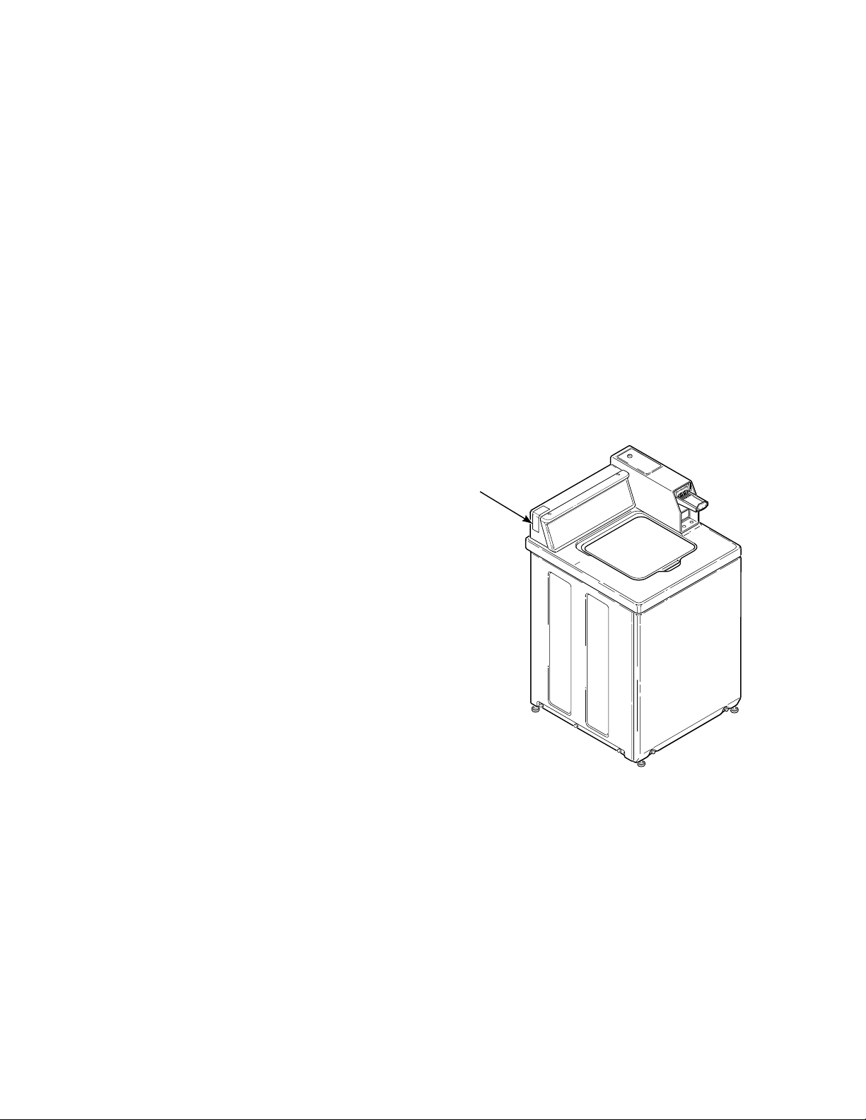
Nameplate Location
When calling or writing about your product, be sure to
mention model and serial numbers. Model and serial
numbers are located on nameplate(s) as shown.
NAMEPLATE
W363PE3A
32918 5
© Copyright, Alliance Laundry Systems LLC – DO NOT COPY or TRANSMIT
Page 7

Section 2 Introduction
Model Identification
Information in this manual is applicable to these washers.
Model
Numbers
Electronic
Models
Card
Models
Metered
Models
Nonmetered
Models
One Speed
Motor
Two Speed
Motor
Porcelain
Was htub
Stainless
Steel
Was htub
EE1010
EA1011, EA1011G X X X
EA1020, EA1020G X X X
EA1021, EA1021G X X X
EA1110, EA1110P,
EA1110T, EA1210,
EA1210G, EA1710 X X X
EA1111, EA1111P,
EA1111T, EA1211 X X X
EA1120, EA1120P,
EA1120T, EA1220,
EA1220G, EA1220P,
EA1220T X X X
EA1121, EA1121P,
EA1121T, EA1221,
EA1221G, EA1721 X X X
EA1310, EA1310G X X X
EA1311, EA1311G X X X
EA1420 X X X
EA1421 X X X
EA1510G, EA1610 X X X
EA1520, EA1520G,
EA1520P, EA1520T,
EA1620 X X X
EA1521, EA1521G,
EA1621 X X X
XX X
6 32918
© Copyright, Alliance Laundry Systems LLC – DO NOT COPY or TRANSMIT
Page 8
Section 3
Troubleshooting
WARNING
To reduce the risk of electric shock, fire, explosion, serious injury or death:
• Disconnect electric power to the washer before servicing.
• Never start the washer with any guards/panels removed.
• Whenever ground wires are removed during servicing, these ground wires must be
reconnected to ensure that the washer is properly grounded.
IMPORTANT: Refer to appropriate Wiring Diagram for aid in testing washer components.
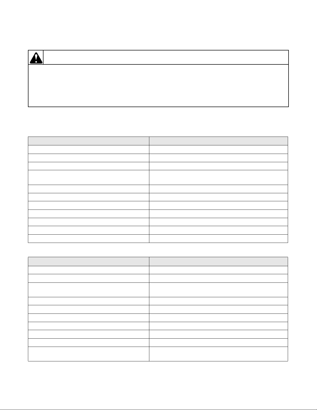
1. NO HOT WATER
POSSIBLE CAUSE TO CORRECT
Hot water supply faucet is closed. • Open faucet.
Water supply is cold. • Check water heater.
Kinked hot water inlet hose. • Straighten or replace hose.
Clogged mixing valve screen, or clogged screen in
outer end of inlet hose nearest water supply faucet.
Inoperative hot water mixing valve solenoid. • Test solenoid and replace if inoperative.
*Inoperative timer. • Test timer and replace if inoperative.
*Inoperative temperature switch. • Test switch and replace if inoperative.
Inoperative pressure switch. • Test switch and replace if inoperative.
Clogged pressure hose. • Remove and clean or replace hose.
Broken, loose or incorrect wiring. • Refer to appropriate wiring diagram.
†Inoperative electronic control. • Refer to Section 8 to check out the electronic control.
• Disconnect hot water inlet hose, and clean or replace
screen(s).
W003
2. NO COLD WATER
POSSIBLE CAUSE TO CORRECT
Cold water supply faucet is closed. • Open faucet.
Kinked cold water inlet hose. • Straighten or replace hose.
Clogged mixing valve screen, or clogged screen in
outer end of inlet hose nearest water supply faucet.
Inoperative cold water mixing valve solenoid. • Test solenoid and replace if inoperative.
*Inoperative timer. • Test timer and replace if inoperative.
*Inoperative temperature switch. • Test switch and replace if inoperative.
Inoperative pressure switch. • Test switch and replace if inoperative.
Clogged pressure hose. • Remove and clean or replace hose.
Broken, loose or incorrect wiring. • Refer to appropriate wiring diagram.
†Inoperative electronic control. • Refer to Section 8 to check out the electronic control
* Mechanical Timer Models only
† Electronic Control Models only
32918 7
© Copyright, Alliance Laundry Systems LLC – DO NOT COPY or TRANSMIT
• Disconnect cold water inlet hose, and clean or replace
screen(s).
operation.
Page 9
Section 3 Troubleshooting
WARNING
To reduce the risk of electric shock, fire, explosion, serious injury or death:
• Disconnect electric power to the washer before servicing.
• Never start the washer with any guards/panels removed.
• Whenever ground wires are removed during servicing, these ground wires must be
reconnected to ensure that the washer is properly grounded.
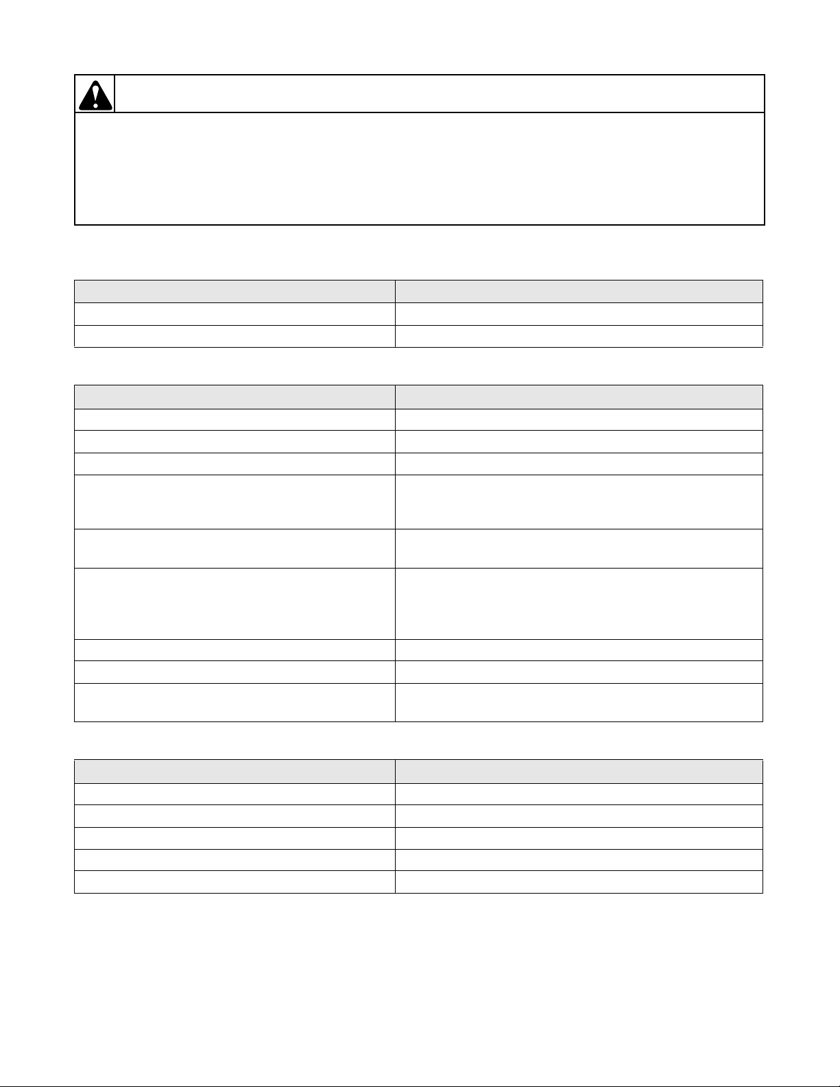
3. NO WARM WATER
POSSIBLE CAUSE TO CORRECT
No hot water. • Refer to Paragraph 1.
No cold water. • Refer to Paragraph 2.
4. WATER FILL DOES NOT STOP AT PROPER LEVEL
POSSIBLE CAUSE TO CORRECT
*Inoperative timer. • Test timer and replace if inoperative.
Inoperative pressure switch. • Test switch and replace if inoperative.
Air leak in pressure hose. • Replace hose.
Sediment on or under mixing valve diaphragm,
defective diaphragm, or armature binding in
armature guide.
Broken, weak or missing mixing valve armature
spring.
Siphoning action started in washer which will cause
water to be siphoned from washer during cycle due
to end of drain hose being lower than drain elbow at
rear of washer.
Water in pressure hose. • Blow air through hose to remove water.
Broken, loose, shorted or incorrect wiring. • Refer to appropriate wiring diagram.
†Inoperative electronic control • Refer to Section 8 to check out the electronic control
• Disassemble and clean mixing valve. Replace
deteriorated or not-easily-cleaned components.
• Disassemble valve and replace spring, or replace
complete valve.
• Install No. 562P3 Siphon Break Kit.
operation.
W003
5. TIMER DOES NOT ADVANCE (Mechanical Timer Models only)
POSSIBLE CAUSE TO CORRECT
*Timer is designed to pause during fill periods. • Allow for completion of fill period.
*Inoperative timer. • Test timer and replace if inoperative.
Loading door is open. • Close loading door.
Washer will not fill. • Timer pauses until pressure switch is satisfied.
Broken, loose or incorrect wiring. • Refer to appropriate wiring diagram.
* Mechanical Timer Models only
† Electronic Control Models only
8 32918
© Copyright, Alliance Laundry Systems LLC – DO NOT COPY or TRANSMIT
Page 10
Section 3 Troubleshooting
WARNING
To reduce the risk of electric shock, fire, explosion, serious injury or death:
• Disconnect electric power to the washer before servicing.
• Never start the washer with any guards/panels removed.
• Whenever ground wires are removed during servicing, these ground wires must be
reconnected to ensure that the washer is properly grounded.
6. NO AGITATION
POSSIBLE CAUSE TO CORRECT
*Inoperative timer. • Test timer and replace if inoperative.
Inoperative action switch. • Test switch and replace if inoperative.
Inoperative motor. • Test motor and replace if inoperative.
Inoperative pressure switch. • Test switch and replace if inoperative.
Broken, loose or incorrect wiring. • Refer to appropriate wiring diagram.
Loose or broken drive belt. • Adjust or replace belt.
Inoperative transmission assembly. • Repair or replace transmission assembly.
Sheared motor pulley roll pin. • Remove drive motor and replace roll pin and any other
damaged parts.
Drive motor overload protector has cycled. • Refer to Paragraph 10.
Bind in pump. • Disassemble and clean pump or replace pump.
Loading door is open or door switch is inoperative. • Close door or test switch and replace if inoperative.
†Inoperative electronic control • Refer to Section 8 to check out the electronic control
operation.
W003
7. CONSTANT AGITATION
POSSIBLE CAUSE TO CORRECT
*Inoperative timer. • Test timer and replace if inoperative.
Inoperative speed switch. • Test switch and replace if inoperative.
Shorted or incorrect wiring. • Refer to appropriate wiring diagram.
†Inoperative electronic control • Refer to Section 8 to check out the electronic control
operation.
* Mechanical Timer Models only
† Electronic Control Models only
32918 9
© Copyright, Alliance Laundry Systems LLC – DO NOT COPY or TRANSMIT
Page 11
Section 3 Troubleshooting
WARNING
To reduce the risk of electric shock, fire, explosion, serious injury or death:
• Disconnect electric power to the washer before servicing.
• Never start the washer with any guards/panels removed.
• Whenever ground wires are removed during servicing, these ground wires must be
reconnected to ensure that the washer is properly grounded.
8. SLOW SPIN OR NO SPIN
POSSIBLE CAUSE TO CORRECT
*Inoperative timer. • Test timer and replace if inoperative.
Inoperative speed switch. • Test switch and replace if inoperative.
Loading door is open or door safety switch is
inoperative.
Bind in water pump. • Replace pump.
Inoperative drive motor. • Test motor and replace if inoperative.
Loose or broken drive belt. • Adjust or replace belt.
Washer has gone out of balance. • Open loading door to reset out-of-balance switch.
No clearance or stuck brake pads. • Free sticky brake pads or replace pads.
Broken, loose or incorrect wiring. • Refer to appropriate wiring diagram.
†Inoperative electronic control • Refer to Section 8 to check out the electronic control
• Close loading door, or test switch and replace if
inoperative.
operation.
W003
9. CONSTANT SPIN
POSSIBLE CAUSE TO CORRECT
*Inoperative timer. • Test timer and replace if inoperative.
Inoperative drive motor. • Test motor and replace if inoperative.
Excessive wear on brake pads, or missing brake
• Replace brake pads.
pads.
Shorted or incorrect wiring. • Refer to appropriate wiring diagram.
†Inoperative electronic control • Refer to Section 8 to check out the electronic control
operation.
10. DRIVE MOTOR OVERLOAD PROTECTOR CYCLES REPEATEDLY
POSSIBLE CAUSE TO CORRECT
Excessive belt tension. • Adjust belts.
Inoperative motor overload protector. • Replace motor.
Bind in water pump. • Replace pump.
Bind in transmission. • Repair or replace transmission.
Brake pads binding. • Free binding pads, or replace pads.
* Mechanical Timer Models only
† Electronic Control Models only
10 32918
© Copyright, Alliance Laundry Systems LLC – DO NOT COPY or TRANSMIT
Page 12
Section 3 Troubleshooting
WARNING
To reduce the risk of electric shock, fire, explosion, serious injury or death:
• Disconnect electric power to the washer before servicing.
• Never start the washer with any guards/panels removed.
• Whenever ground wires are removed during servicing, these ground wires must be
reconnected to ensure that the washer is properly grounded.
11. OUTER TUB DOES NOT EMPTY
POSSIBLE CAUSE TO CORRECT
Kinked drain hose. • Straighten hose.
Obstruction in outer tub outlet hose. • Remove obstruction.
Inoperative water pump. • Dissassemble and clean pump or replace pump.
Loosen or broken pump belt. • Adjust or replace belt.
12. EXCESSIVE VIBRATION
POSSIBLE CAUSE TO CORRECT
Unbalanced load in tub. • Stop washer, redistribute load, then restart washer.
Broken, disconnected or incorrectly adjusted
centering spring(s) out of adjustment.
Washer is not properly leveled. • Adjust leveling legs.
Washer is installed on weak, “spongy”, carpeted or
built-up floor.
Incorrect or loose cabinet screws. • Replace with correct screws or tighten.
• Connect or replace centering spring(s). Spring should be
positioned as shown in Figure 56.
• Relocate washer, or support floor to eliminate weak or
“spongy” condition.
W003
13. WATER LEAKING FROM OUTER TUB
POSSIBLE CAUSE TO CORRECT
Leaking water seal in outer tub. • Replace hub and seal kit assembly, Paragraph 43
Hole in outer tub. • Replace outer tub.
Pressure hose or accumulator leaking. • Replace pressure hose and/or accumulator.
Outer tub cover gasket leaking. • Replace gasket.
Obstruction in drain causing water to come over top
• Remove obstruction.
of outer drain tub cover.
Tub-to-pump hose leaking at clamp. • Tighten clamp.
32918 11
© Copyright, Alliance Laundry Systems LLC – DO NOT COPY or TRANSMIT
Page 13

Section 3 Troubleshooting
Notes
12 32918
© Copyright, Alliance Laundry Systems LLC – DO NOT COPY or TRANSMIT
Page 14
Section 4
Grounding
WARNING
To reduce the risk of electric shock, fire, explosion, serious injury or death:
• Disconnect electric power to the washer before servicing.
• Never start the washer with any guards/panels removed.
• Whenever ground wires are removed during servicing, these ground wires must be
reconnected to ensure that the washer is properly grounded.
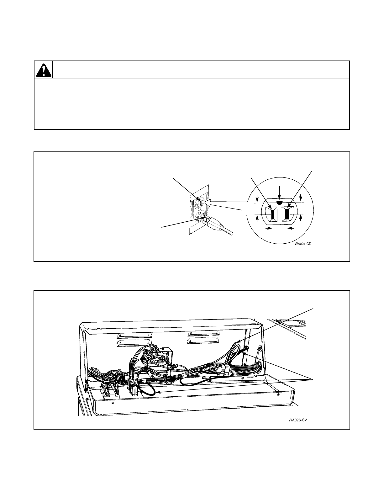
14. WALL RECEPTACLE POLARITY CHECK
W003
NOTE: Have a qualified
electrician check
polarity of wall
receptacle. If a voltage
Neutral
Side
L1
Ground
Neutral
reading is measured
other than that
illustrated, the qualified
electrician should
115 ± 12
VAC
0
VAC
correct the problem.
Round
Grounding
Prong
Figure 1
115 ± 12
VAC
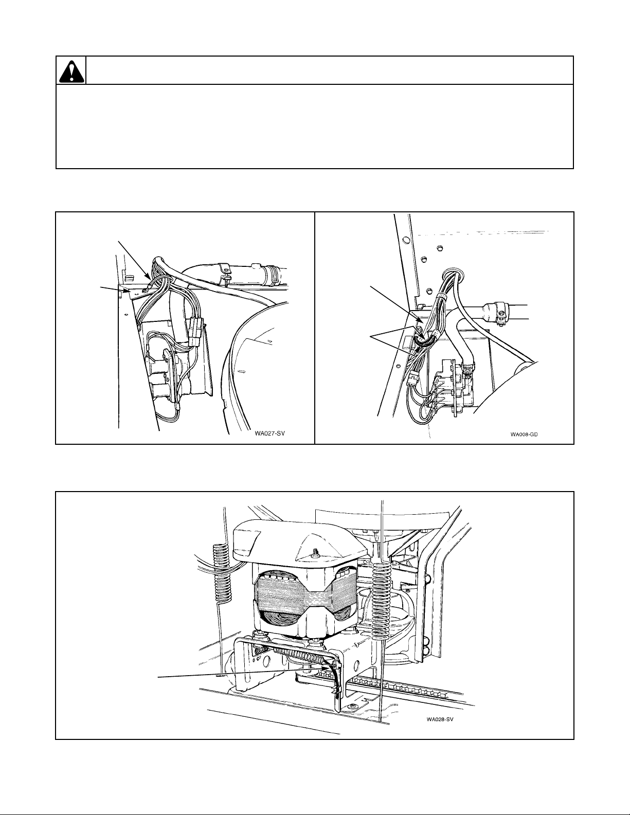
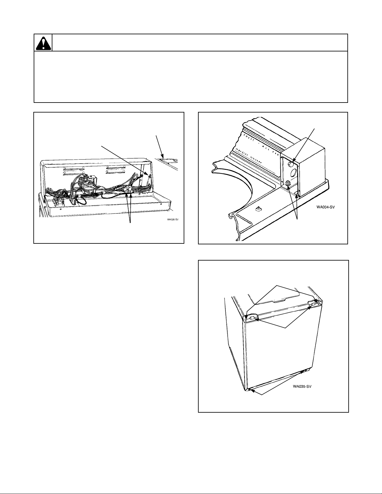
15. POWER CORD TO CONTROL HOOD, CONTROL HOOD TO THE CONTROL PANEL FRAME
Power
Cord
Ground
Wires
Figure 2
32918 13
© Copyright, Alliance Laundry Systems LLC – DO NOT COPY or TRANSMIT
Page 15
Section 4 Grounding
WARNING
To reduce the risk of electric shock, fire, explosion, serious injury or death:
• Disconnect electric power to the washer before servicing.
• Never start the washer with any guards/panels removed.
• Whenever ground wires are removed during servicing, these ground wires must be
reconnected to ensure that the washer is properly grounded.
16. CONTROL HOOD WIRE HARNESS TO TOP LEFT REAR CORNER GUSSET OF CABINET
Ground
Wires
Corner
Corner
Gusset
Gusset
Ground
Wires
W003
17. MOTOR TO MOUNTING BRACKET
Ground
Wire
Figure 3
Figure 4
14 32918
© Copyright, Alliance Laundry Systems LLC – DO NOT COPY or TRANSMIT
Page 16
Section 5
Service Procedures
WARNING
To reduce the risk of electric shock, fire, explosion, serious injury or death:
• Disconnect electric power to the washer before servicing.
• Never start the washer with any guards/panels removed.
• Whenever ground wires are removed during servicing, these ground wires must be
reconnected to ensure that the washer is properly grounded.
b. Loosen setscrew holding switch knob to switch
WARNING
Do not repair or replace any part of the
washer or attempt any servicing unless
specifically recommended in the UserMaintenance Instructions or in published
user-repair instructions that you
understand and have the skills to carry
out.
IMPORTANT: When reference is made to
directions (right or left) in this manual, it is from
operator’s position facing front of washer.
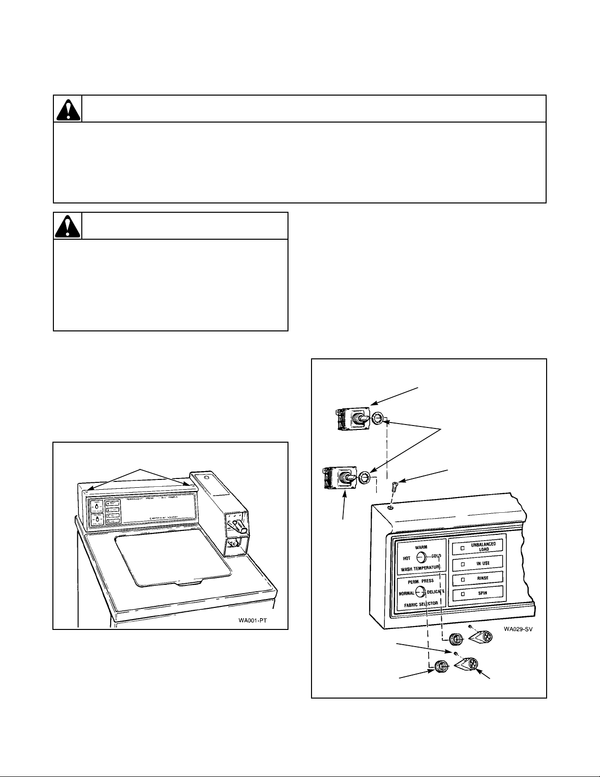
18. CONTROL PANEL
Refer to Figure 5.
a. Remove two control panel attaching screws and
lift assembly off cabinet top.
NOTE: Lockwasher must be between switch and
control panel when installing switch. Refer to
Figure 6.
NOTE: Refer to appropriate wiring diagram when
rewiring switch.
shaft. Refer to Figure 6.
c. Remove knurled nut holding switch to control
panel. Refer to Figure 6.
d. Disconnect wires from switch.
Wash
Temperature
Switch
Lockwasher
W003
Panel
Attaching Screws
Figure 5
19. SPEED OR WASH TEMPERATURE
SWITCH
a. Remove two control panel attaching screws and
lift assembly off cabinet top. Refer to Figure 5.
Speed
Switch
Setscrew
Knurled
Nut
Panel Screw
Knob
Figure 6
32918 15
© Copyright, Alliance Laundry Systems LLC – DO NOT COPY or TRANSMIT
Page 17
Section 5 Service Procedures
WARNING
To reduce the risk of electric shock, fire, explosion, serious injury or death:
• Disconnect electric power to the washer before servicing.
• Never start the washer with any guards/panels removed.
• Whenever ground wires are removed during servicing, these ground wires must be
reconnected to ensure that the washer is properly grounded.
W003
20. INDICATOR LIGHTS – UNBALANCED
LOAD, IN USE, RINSE OR SPIN
a. Remove two control panel attaching screws and
lift assembly off cabinet top.
b. Disconnect wires from light.
NOTE: Refer to wiring diagram when rewiring
light.
c. Squeeze locking tabs together and pull light out
from rear of panel.
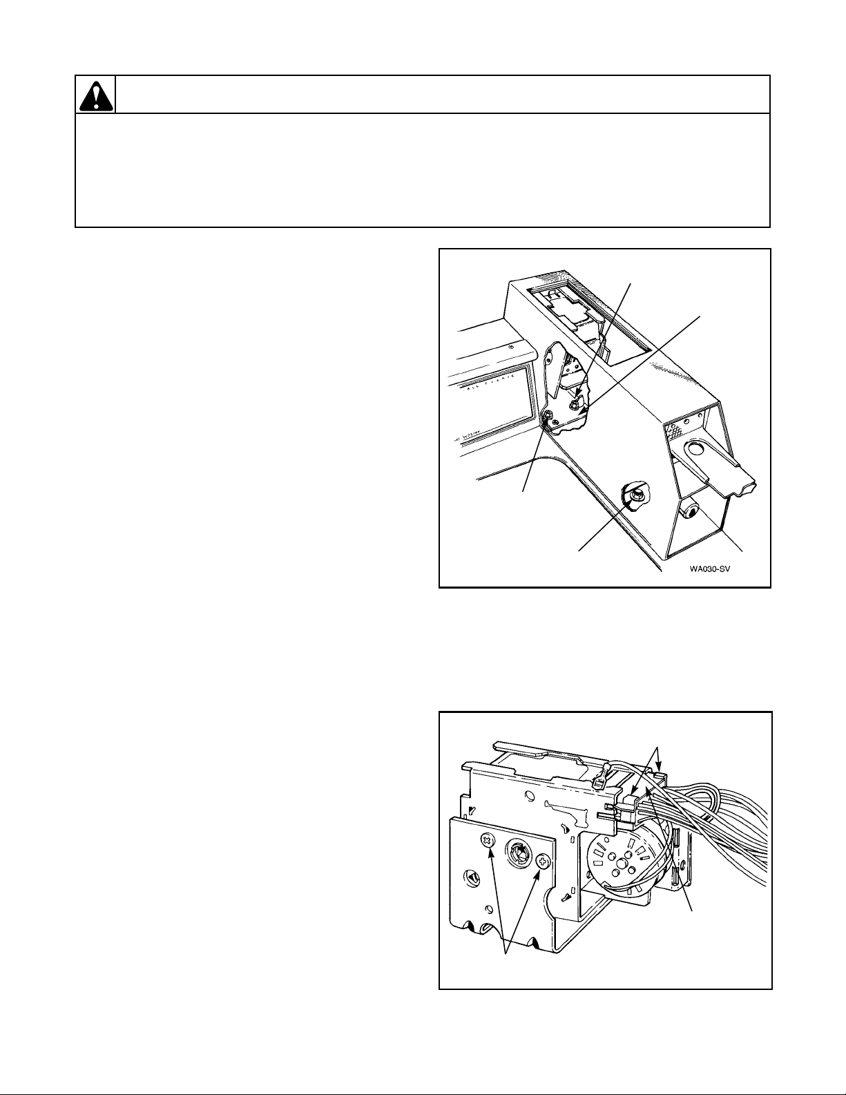
21. TIMER ASSEMBLY – Metered Models
a. Unlock and remove the service door.
b. Remove the inner timer bracket cap screw.
Refer to Figure 7.
c. Slide timer and bracket to the left to disengage
the bracket from shoulder screw. Lift timer and
bracket up and out of meter case through
service door opening as far as wires will permit.
NOTE: DO NOT attempt to repair the timer.
d. Disengage wire harness terminal block plug
from timer by pressing in movable locking tabs
(located on each side of terminal block plug).
Refer to Figure 8. Then pull terminal block
plug away from timer.
Shoulder
Screw
Timer
Bracket
Inner
Cap Screw
Meter Case
Bolt
Figure 7
NOTE: When installing clutch, be sure clutch
moves freely after setscrews are tightened.
IMPORTANT: Be careful not to dislodge or damage
two timer motor lead wires while handling timer.
IMPORTANT: To avoid an open circuit, DO NOT
pull on terminal block wires when removing block
Locking
Tabs
from timer as this could damage wires or terminal
crimpings. Before attaching wire harness terminal
blocks to timer, be sure all male terminals on timer
are straight and are capable of accepting terminals
from wire harness terminal blocks.
NOTE: To avoid timer damage, do not allow timer
to be struck on corners, edges of frame or on timer
shaft.
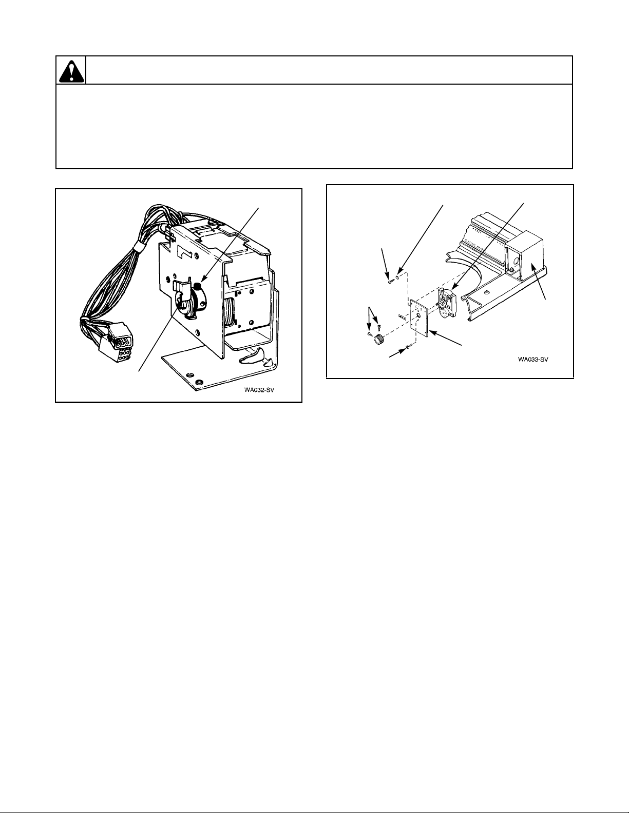
e. Remove two screws holding timer to bracket.
Refer to Figure 8.
f. Loosen setscrew holding clutch to timer shaft.
Refer to Figure 9.
16 32918
© Copyright, Alliance Laundry Systems LLC – DO NOT COPY or TRANSMIT
Timer Bracket
Attaching Screws
Figure 8
Terminal
Block
Plug
Page 18
Section 5 Service Procedures
WARNING
To reduce the risk of electric shock, fire, explosion, serious injury or death:
• Disconnect electric power to the washer before servicing.
• Never start the washer with any guards/panels removed.
• Whenever ground wires are removed during servicing, these ground wires must be
reconnected to ensure that the washer is properly grounded.
W003
Setscrew
Clutch
Figure 9
22. TIMER ASSEMBLY (Nonmetered Models)
Refer to Figure 10.
a. Loosen two setscrews holding timer knob to
timer shaft.
b. Remove four screws and lockwashers holding
timer and plate to timer case.
NOTE: When reinstalling timer and plate,
lockwashers must be between head of screws and
timer plate.
c. Pull timer and plate out of timer case as far as
wires will permit.
NOTE: Disconnect ground wire from rear of timer.
d. Pull wire harness and blocks through into timer
housing; then disconnect timer harness from
control hood harness at quick disconnect block.
e. Remove two screws holding timer to timer
plate.
f. Disconnect wires from timer.
NOTE: Refer to appropriate wiring diagram when
rewiring timer.
Timer
Timer
Case
Timer Plate
Attaching
Screw
Timer Knob
Screws
Timer
Attaching Screw
Lockwasher
Timer
Plate
Figure 10
23. METER CASE (Metered Models)
a. Unlock and remove service door.
b. Remove the inner timer bracket cap screw.
Refer to Figure 7.
c. Slide timer and bracket to the left to disengage
bracket from shoulder screw.
d. Remove two control panel attaching screws and
lift assembly off cabinet top. Refer to Figure 5.
e. Disconnect timer harness from control hood
harness at disconnect blocks. Refer to
Figure 11.
f. Remove timer, bracket and harness out through
service door opening.
g. Remove cap screw, lockwashers and nut
holding meter case to end of control hood.
Refer to Figure 11.
h. Remove coin drawer.
i. Open loading door, hold hand under front meter
case bolt. Refer to Figure 7. Remove nut and
lockwasher.
j. Remove shoulder screw from inside meter case.
NOTE: When installing meter case, shoulder screw
must be installed in outer hole, refer to Figure 7, to
enable timer bracket to slide under screw head.
k. Carefully remove meter case from cabinet top.
32918 17
© Copyright, Alliance Laundry Systems LLC – DO NOT COPY or TRANSMIT
Page 19
Section 5 Service Procedures
WARNING
To reduce the risk of electric shock, fire, explosion, serious injury or death:
• Disconnect electric power to the washer before servicing.
• Never start the washer with any guards/panels removed.
• Whenever ground wires are removed during servicing, these ground wires must be
reconnected to ensure that the washer is properly grounded.
W003
Meter
Case
Meter Case
Screw
Disconnect
Blocks
Figure 11
24. TIMER CASE (Nonmetered Models)
a. Remove timer assembly. Refer to Paragraph
22.
b. Remove two control panel attaching screws and
lift assembly off cabinet top. Refer to Figure 5.
c. Remove cap screw, lockwashers and nut
holding timer case to control hood. Refer to
Figure 12.
d. Remove two screws from bottom edge of front
panel. Refer to Figure 9.
e. Pull bottom of panel away from washer until
hold-down clips (located on top flange of
panel) disengage from slots in cabinet top.
Refer to Figure 13.
f. Remove two cabinet top hold down screws.
Refer to Figure 13.
g. Tape loading door closed and lift cabinet top to
a vertical position.
h. Remove carriage bolts, washers, lockwashers
and nuts holding timer case to cabinet top.
i. Support timer case and remove screw and fiber
washer holding rear of case to cabinet top.
Timer Case
Screw
Timer Case
Attaching
Hardware
Figure 12
Cabinet Top
Hold-Down
Screws
Hold-Down
Clip
Front Panel
Screws
Figure 13
18 32918
© Copyright, Alliance Laundry Systems LLC – DO NOT COPY or TRANSMIT
Page 20
Section 5 Service Procedures
WARNING
To reduce the risk of electric shock, fire, explosion, serious injury or death:
• Disconnect electric power to the washer before servicing.
• Never start the washer with any guards/panels removed.
• Whenever ground wires are removed during servicing, these ground wires must be
reconnected to ensure that the washer is properly grounded.
W003
25. PRESSURE SWITCH
a. Remove two control panel attaching screws and
lift assembly off cabinet top.
b. Remove two screws holding switch to
mounting bracket.
c. Pull switch out of control hood far enough to
disconnect pressure hose and wires from
switch.
NOTE: Refer to appropriate wiring diagram when
rewiring pressure switch.
IMPORTANT: When installing pressure switch,
blow air into hose before connecting hose to switch
to remove any moisture that may have accumulated
in hose.
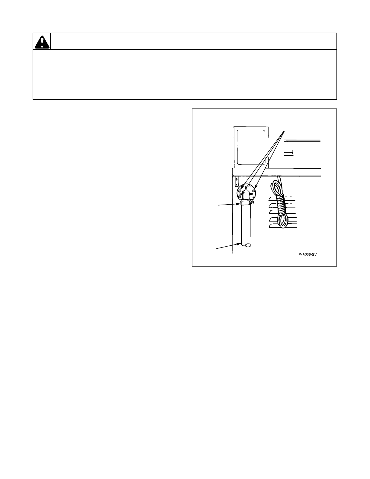
26. DRAIN HOSE ELBOW
Refer to Figure 14
a. Loosen hose clamp and remove drain hose from
elbow.
b. Remove screws holding elbow to rear of
washer cabinet.
c. Pull elbow out through opening in cabinet far
enough to permit loosening inner clamp, then
remove elbow from inner hose.
Elbow
Attaching
Screws
Hose
Clamp
Drain
Hose
Figure 14
NOTE: When installing elbow on inner hose, DO
NOT allow hose inside of washer to twist! Direct
elbow toward drain receptacle and secure elbow to
washer cabinet.
32918 19
© Copyright, Alliance Laundry Systems LLC – DO NOT COPY or TRANSMIT
Page 21
Section 5 Service Procedures
WARNING
To reduce the risk of electric shock, fire, explosion, serious injury or death:
• Disconnect electric power to the washer before servicing.
• Never start the washer with any guards/panels removed.
• Whenever ground wires are removed during servicing, these ground wires must be
reconnected to ensure that the washer is properly grounded.
W003
27. LOADING DOOR
Refer to Figure 15
a. Through Serial No. R8237277YK:
(1) Open loading door. Refer to Figure 15.
(2) Depress tab on either hinge, then slide
hinge out of loading door and bushing in
cabinet top.
(3) Tile loading door slightly and slide door
and hinge out of opposite bushing.
b. Starting Serial No. R8237278YK:
(1) Open loading door. Refer to Figure 15.
(2) Remove two screws holding left hinge to
door and remove hinge. Refer to Figure 15.
Loading
Door
Hinge
(3) With loading door raised to vertical
position, swing left side of door toward
front of washer. Refer to Figure 16,
procedure one.
(4) Rotate loading door so door is upside down.
Refer to Figure 16, procedure two.
(5) Remove loading door, right door hinge and
bushing from cabinet top. Refer to
Figure 16, procedure three.
NOTE: Reverse procedures when installing loading
door.
Loading
Door
Left
Hinge
Attaching
Screws
Hinge
Right
Hinge
THROUGH SERIAL NO. R8237277YK STARTING SERIAL NO. R8237278YK
Figure 15
20 32918
© Copyright, Alliance Laundry Systems LLC – DO NOT COPY or TRANSMIT
Page 22
Procedure One
Procedure Two
Section 5 Service Procedures
Door
Front
WA082a-SV
Door
Front
Procedure Three
Door
Front
WA082b-SV
WA082c-SV
Figure 16
32918 21
© Copyright, Alliance Laundry Systems LLC – DO NOT COPY or TRANSMIT
Page 23
Section 5 Service Procedures
WARNING
To reduce the risk of electric shock, fire, explosion, serious injury or death:
• Disconnect electric power to the washer before servicing.
• Never start the washer with any guards/panels removed.
• Whenever ground wires are removed during servicing, these ground wires must be
reconnected to ensure that the washer is properly grounded.
28. GRAPHIC OVERLAY
Refer to Figure 6
a. Loosen setscrews holding speed and wash
temperature switch knobs to switch shafts.
b. Remove knurled nuts holding each switch to
control panel.
NOTE: Lockwashers must be between switches and
control panel when installing switches.
c. Remove graphic overlay.
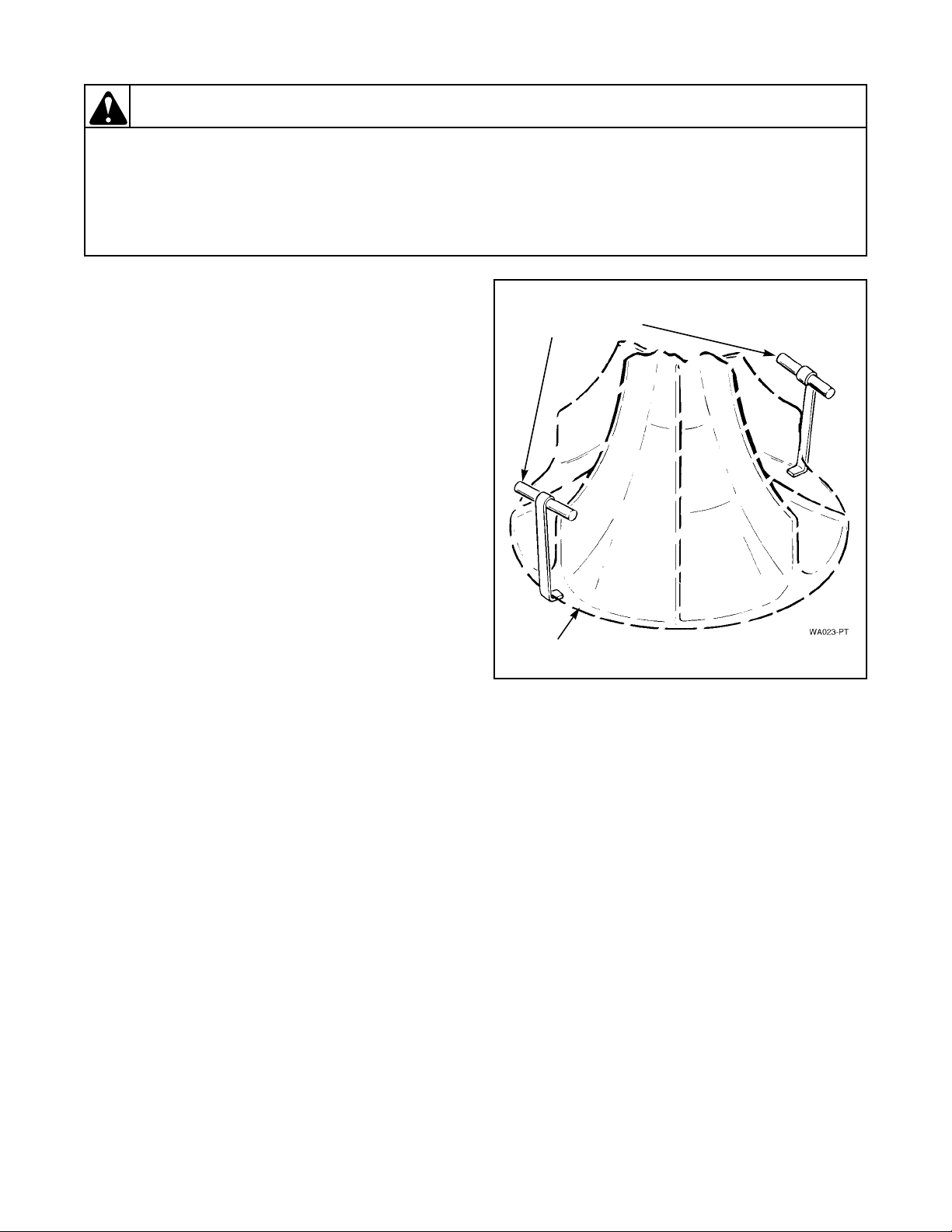
29. AGITATOR
a. Open loading door.
b. To remove agitator by hand, place two agitator
hooks, No. 254P4P, under bottom edge of
agitator. Refer to Figure 17.
No. 254P4P
Agitator Hooks
W003
NOTE: Hooks should be positioned 180 degrees of
each other, and must be placed under the agitator
vane for greater stability. If hooks are placed
between the vane area, damage to the agitator may
occur.
c. Using a rocking motion (back and forth)
carefully lift agitator off drive bell.
30. AGITATOR, DRIVE BELL AND SEAL
ASSEMBLY
a. Open loading door.
NOTE: If water is present in the washtub, spin and
pump out before attempting to remove the drive
bell and seal seat assembly.
b. To remove agitator by hand, place two agitator
hooks, No. 254P4P, under bottom edge of
agitator. Refer to Figure 17.
IMPORTANT: Hooks should be positioned 180
degrees of each other, and must be placed under
agitator vane for greater stability. If hooks are
placed between the vane area, damage to agitator
may occur.
Agitator
Figure 17
d. Remove the screw and o-ring washer from the
top side of the drive bell.
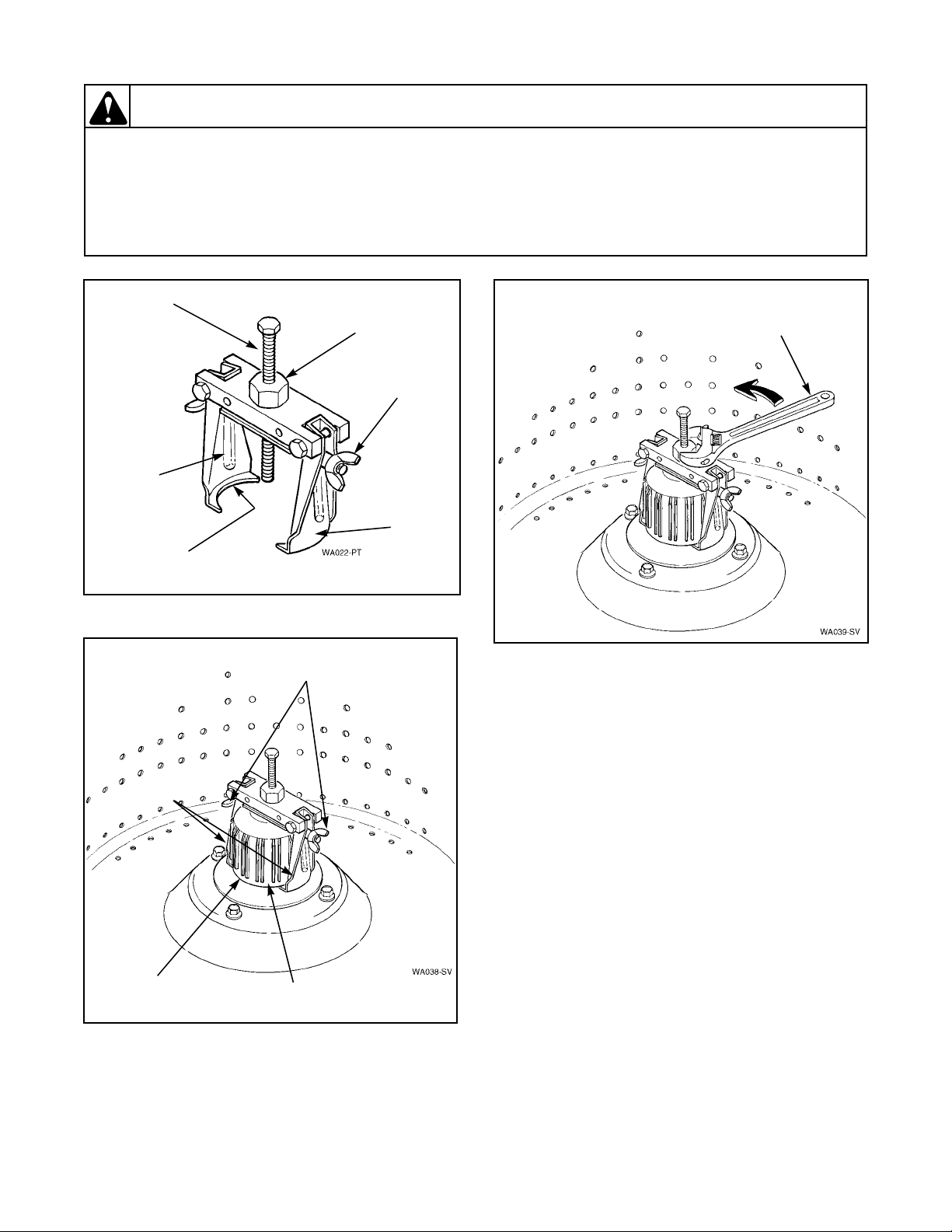
NOTE: To remove the drive bell from the
transmission shaft will require using the No. 294P4
Drive Bell Tool. Refer to Figure 18.
e. Back the one quarter inch bolt out of tool
approximately three quarters of the way.
f. Place tool over drive bell, making sure indent of
the jaw lines up with wide slots on drive bell.
Refer to Figure 19.
c. Using a rocking motion (back and forth)
carefully lift agitator off drive bell.
22 32918
© Copyright, Alliance Laundry Systems LLC – DO NOT COPY or TRANSMIT
Page 24
Section 5 Service Procedures
WARNING
To reduce the risk of electric shock, fire, explosion, serious injury or death:
• Disconnect electric power to the washer before servicing.
• Never start the washer with any guards/panels removed.
• Whenever ground wires are removed during servicing, these ground wires must be
reconnected to ensure that the washer is properly grounded.
W003
Bolt
Indent
Jaws
Jaw
Lip
Figure 18
Wing
Nut
Large
Nut
Turn Adjustable
Wrench Counterclockwise
to Remove Drive Bell
Wing
Nut
Jaw
Figure 20
h. Place lip of each jaw under bottom edge of
drive bell, making sure indent on jaw lines up
with wide slots on drive bell. Then tighten wing
nuts to hold jaws firmly against drive bell.
Refer to Figure 19.
i. Use an adjustable wrench and turn large nut on
tool COUNTERCLOCKWISE to pull drive
bell from transmission shaft. Refer to
Figure 20.
IMPORTANT: If large nut is turned clockwise
when pulling drive bell, you will twist off the
quarter inch bolt.
j. Turn the one quarter inch bolt out of the
transmission shaft and remove tool and drive
Drive
Bell
Wide
Slot
Figure 19
bell from the washer.
k. Loosen the two wing nuts and remove drive bell
from tool.
l. Carefully pry the old seal out of the drive bell
and clean any foreign materials from the bell.
g. Screw the bolt down through hole in top of
drive bell until it bottoms out in the hole of the
shaft.
IMPORTANT: We recommend that both the seal
seat and the seal head be replaced together in pairs.
DO NOT replace only one of the two.
32918 23
© Copyright, Alliance Laundry Systems LLC – DO NOT COPY or TRANSMIT
Page 25
Section 5 Service Procedures
WARNING
To reduce the risk of electric shock, fire, explosion, serious injury or death:
• Disconnect electric power to the washer before servicing.
• Never start the washer with any guards/panels removed.
• Whenever ground wires are removed during servicing, these ground wires must be
reconnected to ensure that the washer is properly grounded.
W003
m. Install the new seal into the drive bell.
n. Remove the seal head from the hub and clean
any foreign material from the hub seal
mounting area.
o. Place the new seal head on hub and carefully
push the seal head into position.
IMPORTANT: Make sure the seal is pressed down
against the shoulder on the hub.
NOTE: Soapy water will aid in the assembly of the
seal onto the hub.
IMPORTANT: DO NOT apply any type of
lubricants to the sealing surfaces of either the seal
seat or seal head as you will damage the seals.
TO REINSTALL DRIVE BELL
a. Position drive bell over transmission shaft.
Rotate drive bell until splines in drive bell line
up with splines on transmission shaft.
b. Place No. 294P4 Bell Tool over top of bell.
Screw bolt into transmission shaft until it
bottoms out.
NOTE: It is not necessary to use the tool jaws on
drive bell during this operation.
g. A sharp blow on top of agitator, with palm of
your hand, will force agitator down onto drive
bell, allowing fingers on underside of agitator
to lock under bottom edge of drive bell.
NOTE: Do not push agitator onto drive bell any
further than necessary.
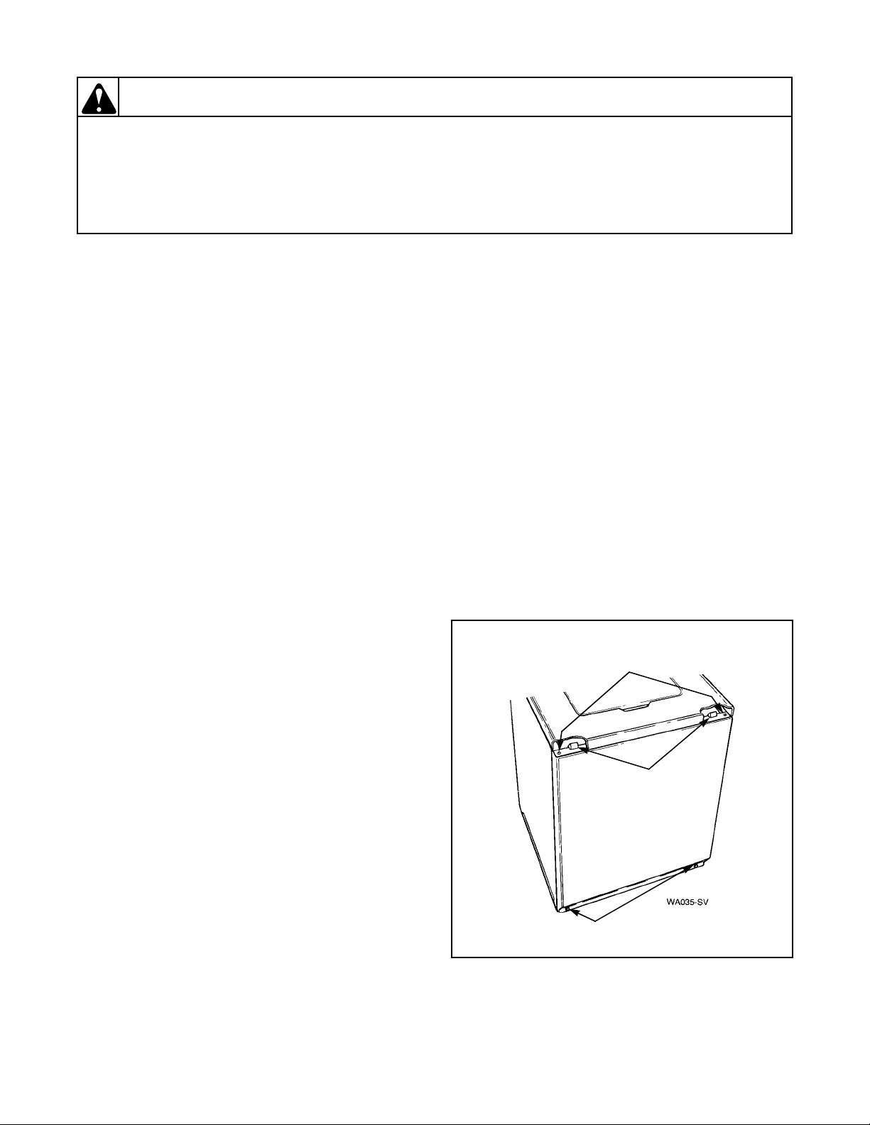
31. FRONT PANEL
Refer to Figure 21
a. Remove two screws from bottom edge of front
panel.
b. Pull bottom of panel away from washer until
hold down clips (located on top flange of panel)
disengage from slots in cabinet top.
Hold-Down Clips
Compress hold-down clips enough to remove
them from slots in top flange of panel.
Guide Lugs
Remove screws holding guide lugs to side flanges
of front panel.
Cabinet Top
Hold-Down
Screws
c. Use an adjustable wrench and turn large nut on
tool CLOCKWISE to force drive bell down
onto transmission shaft until bell bottoms out
on shaft.
d. Turn bolt out of transmission shaft and remove
Hold-Down
Clip
tool.
e. Place new o-ring gasket onto new screw.
Thread the new screw down through hole in top
of drive bell and into transmission shaft. DO
NOT reuse the old screw and o-ring gasket!
NOTE: Torque new screw down between 45 to 55
inch pounds (5 to 6.2 Nm). Over torque will
mushroom the plastic bell.
f. Place agitator on top of drive bell. Slowly rotate
Front Panel
Screws
Figure 21
agitator until fingers on underside of agitator
line up with large slots on drive bell.
24 32918
© Copyright, Alliance Laundry Systems LLC – DO NOT COPY or TRANSMIT
Page 26
Section 5 Service Procedures
WARNING
To reduce the risk of electric shock, fire, explosion, serious injury or death:
• Disconnect electric power to the washer before servicing.
• Never start the washer with any guards/panels removed.
• Whenever ground wires are removed during servicing, these ground wires must be
reconnected to ensure that the washer is properly grounded.
W003
32. PUMP BELT
a. Remove front panel. Refer to Paragraph 31.
b. Remove two front mounting screws and loosen
the rear mounting screw holding pump and
bracket to washer base. Refer to Figure 22.
Pivot entire assembly toward motor to loosen
belt tension.
c. Run belt off motor pulley, then remove belt
from pump pulley.
NOTE: After installing pump belt, adjust belt.
Refer to Paragraph 55.
d. While holding idler lever, reach in and around
right side of motor and run belt off right side of
large drive pulley. Refer to Figure 23.
e. Remove belt from motor pulley and pull belt
out through front of motor mount.
IMPORTANT: Drive belt MUST be replaced with
belt No. 28808 (special clutch-type belt) for proper
washer operation.
TO INSTALL NO. 28808 DRIVE BELT
NOTE: If the new belt is replacing a burned belt,
the motor pulley “V” groove must be polished with
a fine (320 grit) emery cloth to remove the rubber
residue. The residue will affect the washer spin
operation.
a. Push belt in through front of motor mount and
place belt on motor pulley.
b. Reach in and around right side of motor,
starting with belt on right side of large drive
pulley, run belt onto pulley.
c. Reach in through front of motor mount and
move idler lever to the left.
Pump
Attaching
Screws
Pump
Belt
Figure 22
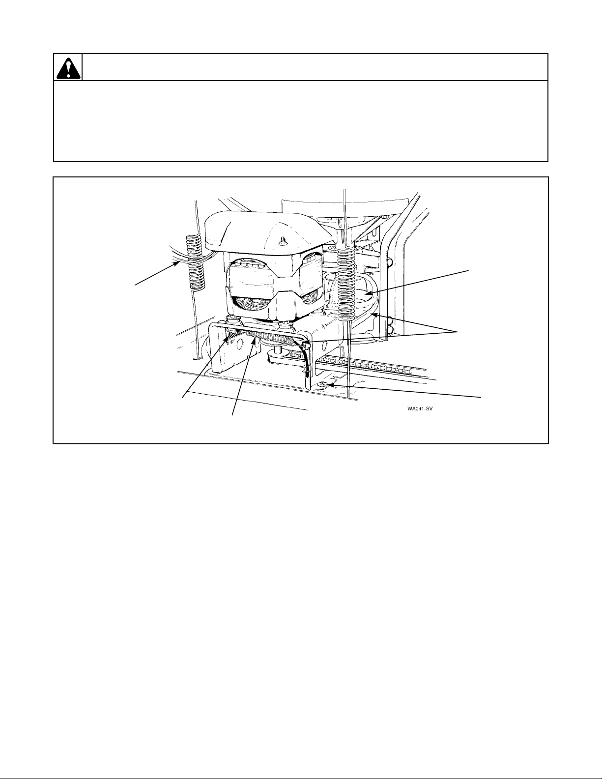
33. DRIVE BELT
a. Remove front panel. Refer to Paragraph 31.
b. Remove two front mounting screws and loosen
the rear mounting screw holding pump and
bracket to washer base. Refer to Figure 22.
Pivot entire assembly toward motor to loosen
belt tension.
c. Reach in through front of motor mount and
move idler lever to the left to release tension on
belt.
IMPORTANT: Use care when releasing the idler
lever tension. If the idler spring or helper spring is
overstretched, washer operation will be affected.
d. While holding idler lever, reach around right
side of motor and place belt on idler pulley.
IDLER PULLEY MUST RIDE ON OUTSIDE
OF BELT.
NOTE: There is no belt adjustment after installing
new drive belt. Check to be sure motor and
mounting bracket have been shifted toward rear of
washer to its limit of travel within the mounting
bracket attaching screws. If the motor and
mounting bracket must be repositioned, loosen the
four motor attaching screws and shift motor and
mounting bracket toward rear of washer to its limit
of travel. Retighten the four attaching screws. Refer
to Figure 24.
e. Install pump belt, adjust per Paragraph 32.
lever tension. If the idler spring or helper spring is
overstretched, washer operation will be affected.
IMPORTANT: Use care when releasing the idler
32918 25
© Copyright, Alliance Laundry Systems LLC – DO NOT COPY or TRANSMIT
Page 27
Section 5 Service Procedures
WARNING
To reduce the risk of electric shock, fire, explosion, serious injury or death:
• Disconnect electric power to the washer before servicing.
• Never start the washer with any guards/panels removed.
• Whenever ground wires are removed during servicing, these ground wires must be
reconnected to ensure that the washer is properly grounded.
Drive
Pulley
Wire harness
must be installed
ahead of spring.
W003
Helper
Spring
Idler
Spring
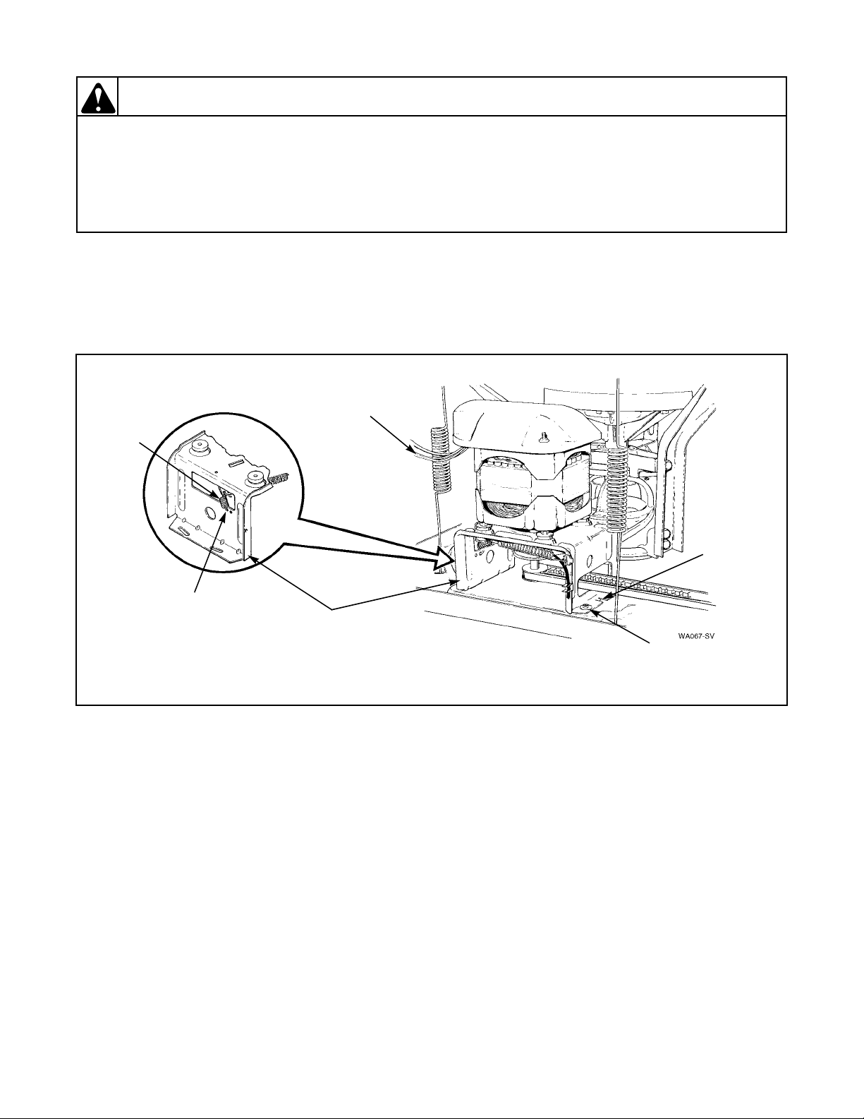
34. MOTOR AND MOUNTING BRACKET
a. Remove front panel. Refer to Paragraph 31.
b. Disconnect motor wire harness from base wire
harness at disconnect blocks. Refer to
Figure 28.
c. Remove pump belt. Refer to Paragraph 32.
Then remove drive belt. Refer to Paragraph 33.
NOTE: When installing belts, adjust pump belt.
Refer to Paragraph 55. There is no drive belt
adjustment.
d. Remove four screws holding motor and
mounting bracket to washer base. Refer to
Figure 24. Then lift complete assembly out of
washer.
Drive
Belt
Motor
Attaching
Screws
Figure 23
NOTE: When installing motor and mounting
bracket, tab on right bottom flange of mounting
bracket must be placed in hole in base. Mounting
bracket must be shifted toward rear of washer to its
limit of travel within the mounting bracket
attaching screws.
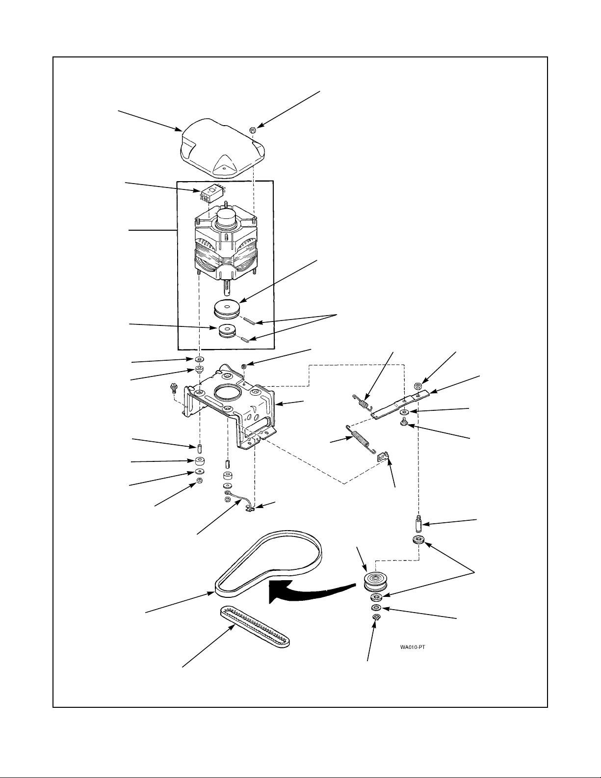
e. Remove nuts, steel washers, spacers and rubber
mounts holding motor to mounting bracket.
Refer to Figure 25. Lift motor off mounting
bracket and remove balance of rubber mounts
and steel washers from motor mounting studs.
IMPORTANT: When installing motor on mounting
bracket, position motor with switch facing toward
left side of mounting bracket.
NOTE: Refer to Figure 25 for motor and mounting
bracket assembly sequence.
26 32918
© Copyright, Alliance Laundry Systems LLC – DO NOT COPY or TRANSMIT
Page 28
Section 5 Service Procedures
WARNING
To reduce the risk of electric shock, fire, explosion, serious injury or death:
• Disconnect electric power to the washer before servicing.
• Never start the washer with any guards/panels removed.
• Whenever ground wires are removed during servicing, these ground wires must be
reconnected to ensure that the washer is properly grounded.
W003
35. IDLER LEVER AND PULLEY
a. Remove motor and mounting bracket. Refer to
Paragraph 34, steps “a” through “d”.
b. Remove nut, washer and bolt holding idler
lever and pulley to motor mounting bracket.
Wire harness
must be installed
ahead of spring.
Helper
Spring
The round spring hook
must be hooked in
rear hole for proper
idler lever operation.
Motor Mounting
Bracket
NOTE: Refer to Figure 25 for idler lever and pulley
assembly sequence.
c. Apply No. 03637P Lubricant to the area of idler
lever that makes contact with motor mounting
bracket.
Positioning
Tab
Motor
Attaching
Screws
Figure 24
32918 27
© Copyright, Alliance Laundry Systems LLC – DO NOT COPY or TRANSMIT
Page 29
Section 5 Service Procedures
Motor
Shield
Motor
Switch
Motor
Pulley
(Pump)
Steel
Washer
Rubber
Mount
Nut
Pulley
(Agitate and Spin)
Roll
Pin
Nut
Motor
Mounting
Bracket
Helper
Spring
Locknut
Idler
Lever
Washer
Spacer
Rubber
Mount
Steel
Washer
Nut
Ground Wire
(Green)
Belt
(Agitate and Spin)
(Pump)
Belt
Spring
Ground Clip
(Clips to the motor
mounting bracket)
Idler
Pulley
Figure 25
Shoulder
Bolt
Clip
Idler
Shaft
Felt
Washers
Nylatron
Washer
Retainer
Ring
28 32918
© Copyright, Alliance Laundry Systems LLC – DO NOT COPY or TRANSMIT
Page 30
Section 5 Service Procedures
WARNING
To reduce the risk of electric shock, fire, explosion, serious injury or death:
• Disconnect electric power to the washer before servicing.
• Never start the washer with any guards/panels removed.
• Whenever ground wires are removed during servicing, these ground wires must be
reconnected to ensure that the washer is properly grounded.
W003
36. MOTOR DRIVE PULLEY OR PUMP
PULLEY
a. Remove motor and mounting bracket. Refer to
Paragraph 34, steps “a” through “d”.
b. Lay motor and mounting bracket on its side.
NOTE: To remove pulleys, support motor shaft (to
prevent bending shaft) and drive out pulley roll
pins.
37. MOTOR SWITCH
a. Remove front panel. Refer to Paragraph 31.
b. Remove nut holding motor shield to motor.
Refer to Figure 25.
c. Disconnect external wires from motor switch
terminals.
NOTE: Refer to appropriate wiring diagram when
rewiring external switch wires.
d. Remove two screws holding switch to motor.
Refer to Figure 25.
e. Disconnect internal motor leads from switch
terminals.
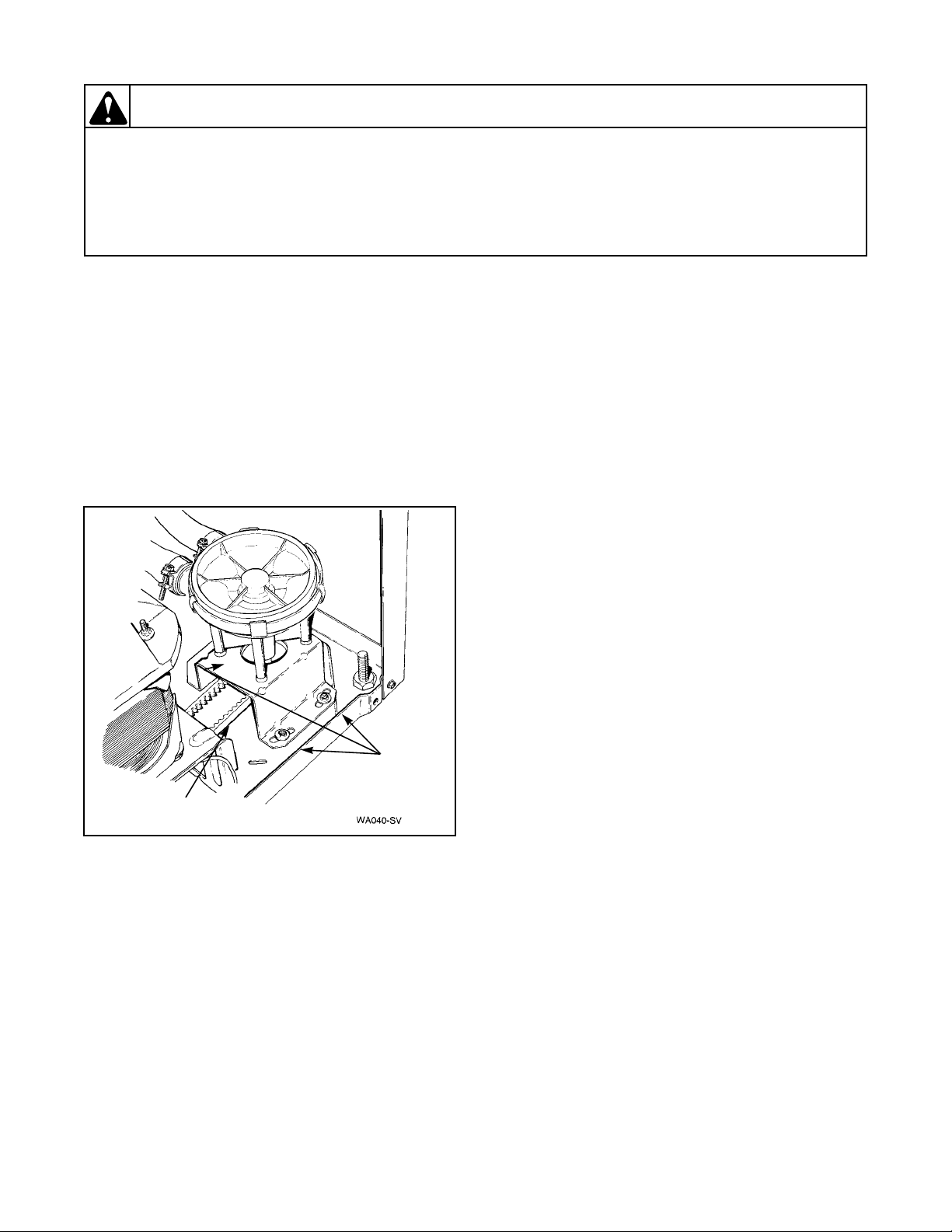
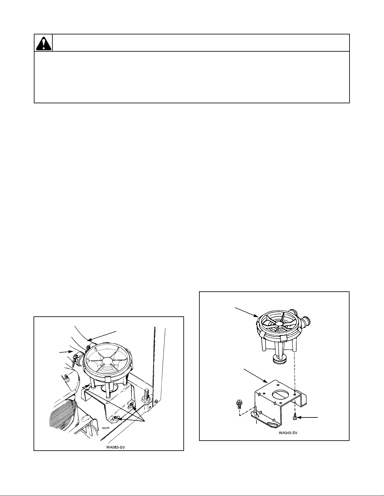
38. PUMP ASSEMBLY
a. Remove front panel. Refer to Paragraph 31.
b. Remove pump belt. Refer to Paragraph 32.
IMPORTANT: There will always be some water
that will remain in the outer tub; therefore, before
removing hoses from the pump, the hoses will have
to be pinched off or drained to prevent water
spillage on the floor.
NOTE: Rear screw hole in pump mounting bracket
is keyhole shaped; therefore, it is not necessary to
remove the rear screw.
c. Slide pump and mounting bracket toward rear
of washer and lift assembly out of washer.
d. Loosen hose clamps and remove hoses from
pump assembly. Refer to Figure 26.
Pump Mounting Bracket
Remove four screws holding pump to mounting
bracket.
NOTE: Refer to Figure 27 for pump and mounting
bracket assembly sequence.
NOTE: Refer to wiring schematics, Section 10, for
rewiring internal switch wires.
Outer Tub
to Pump
Hose
Drain
Hose
Pump
Attaching
Screws
Figure 26
32918 29
© Copyright, Alliance Laundry Systems LLC – DO NOT COPY or TRANSMIT
Pump
Assembly
Pump
Mounting
Bracket
Hex Head
Screw
Figure 27
Page 31

Section 5 Service Procedures
WARNING
To reduce the risk of electric shock, fire, explosion, serious injury or death:
• Disconnect electric power to the washer before servicing.
• Never start the washer with any guards/panels removed.
• Whenever ground wires are removed during servicing, these ground wires must be
reconnected to ensure that the washer is properly grounded.
W003
Wire
Harness
Clip
Disconnect
Blocks
THROUGH SERIAL NO. R8237277YK STARTING SERIAL NO. R8237278YK
Cabinet Top
Hold-Down
Screw
Door Switch and
Out-of-Balance
Switch Assembly
39. CABINET TOP ASSEMBLY
a. Remove two screws from bottom edge of front
panel. Refer to Figure 21.
b. Pull bottom of panel away from washer until
hold down clips (located on top flange of panel)
disengage from slots in cabinet top. Refer to
Figure 28.
c. Remove two cabinet top hold-down screws.
Refer to Figure 28.
d. Metered Models:
(1) Unlock and open meter case service door.
(2) Remove inner cap screw holding the timer
and bracket to the cabinet bracket.
(3) Slide timer and bracket to the left to
disengage bracket from shoulder screw.
Lift timer and bracket out of meter case
through service door opening as far as wires
will permit.
(4) Remove shoulder screw from inside meter
case.
Figure 28
NOTE: Cabinet top is self supporting, however, a
small chain may be used for additional support.
Refer to Figure 29.
Cabinet Top
Wire
Harness
Clip
Disconnect
Blocks
Hold-Down
Screw
e. If area or space permits, tape loading door
closed and lift cabinet top to a vertical position
by hinging it on the rear hold-down bracket.
TO REMOVE CABINET TOP FROM
WASHER
a. Metered Models – Unlock and remove the
service door. Remove the inner cap screw
holding the timer and bracket to the cabinet
bracket.
b. Slide the timer and bracket to the left to
disengage the bracket from the shoulder screw.
Lift timer and bracket out of the meter case
through the service door opening as far as the
wires will permit.
c. Remove the shoulder screw from inside the
meter case.
NOTE: When installing the shoulder screw, it must
be installed in the outer hole to enable the timer
bracket to slide under the screw head. Refer to
Figure 7.
30 32918
© Copyright, Alliance Laundry Systems LLC – DO NOT COPY or TRANSMIT
Page 32

Section 5 Service Procedures
WARNING
To reduce the risk of electric shock, fire, explosion, serious injury or death:
• Disconnect electric power to the washer before servicing.
• Never start the washer with any guards/panels removed.
• Whenever ground wires are removed during servicing, these ground wires must be
reconnected to ensure that the washer is properly grounded.
IMPORTANT: When installing pressure hose, blow
air into hose before connecting hose to switch to
Chain
remove any moisture that may have accumulated in
the hose.
k. Push base wire harness block and pressure hose
down through hole in cabinet top.
l. Tape loading door closed.
m. Lift front of cabinet top slightly and pull
forward to disengage from the rear hold-down
bracket.
W003
Figure 29
NOTE: When reinstalling the shoulder screw, it
must be installed in the outer hole to enable the
timer bracket to slide under the screw head. Refer
to Figure 7.
d. Remove two screws from bottom edge of front
panel. Refer to Figure 21.
e. Pull bottom of panel away from washer until
hold-down clips (located on top flange of
panel) disengage from slots in cabinet top.
f. Remove two cabinet top hold down screws.
Refer to Figure 28.
g. Remove two control panel attaching screws.
Refer to Figure 5.
h. Lift control panel up and out of the slots in the
cabinet top. Lay the control panel face down on
some protective padding on the cabinet top.
i. Disconnect control hood harness from base
wire harness at the quick disconnect blocks.
Refer to Figure 30.
j. Disconnect pressure hose from pressure switch.
WARNING
To reduce the risk of personal injury, be
careful not to damage door switch and outof-balance switch assembly when removing
cabinet top.
n. Pull top forward far enough to permit
disconnecting the green ground wires from top
rear corner gusset of washer cabinet. Refer to
Figure 31. Disconnect wires from mixing valve
solenoids at rear of washer.
NOTE: Refer to appropriate wiring diagram when
rewiring mixing valve solenoids.
o. Carefully lift cabinet top off washer and set
alongside the washer cabinet on protective
padding.
p. Starting Serial No. R8237278YK:
WARNING
To reduce the risk of personal injury, be
careful not to damage door switch and outof-balance switch assembly when removing
cabinet top.
IMPORTANT: When reinstalling cabinet top and
before lowering top into position, pivot outer tub
forward far enough to prevent damaging (bending)
out-of-balance switch lever.
32918 31
© Copyright, Alliance Laundry Systems LLC – DO NOT COPY or TRANSMIT
Page 33

Section 5 Service Procedures
WARNING
To reduce the risk of electric shock, fire, explosion, serious injury or death:
• Disconnect electric power to the washer before servicing.
• Never start the washer with any guards/panels removed.
• Whenever ground wires are removed during servicing, these ground wires must be
reconnected to ensure that the washer is properly grounded.
W003
Control Hood
and Base
Wire Harness
Disconnect
Blocks
Ground Wires
(Green)
Pressure
Hose
Pressure
Switch
Control Panel
Assembly
Figure 30
Pressure
Hose
Pressure
Hose
Mixing Valve
Assembly
Corner
Gusset
Mixing Valve
Wire Harness
Mixing Valve
Assembly
THROUGH SERIAL NO. R8237277YK
Disconnect
Blocks
Corner
Gusset
Ground
Wires
(Green)
Mixing Valve
Disconnect
Blocks
STARTING SERIAL NO. R8237278YK
Figure 31
32 32918
© Copyright, Alliance Laundry Systems LLC – DO NOT COPY or TRANSMIT
Page 34

Section 5 Service Procedures
WARNING
To reduce the risk of electric shock, fire, explosion, serious injury or death:
• Disconnect electric power to the washer before servicing.
• Never start the washer with any guards/panels removed.
• Whenever ground wires are removed during servicing, these ground wires must be
reconnected to ensure that the washer is properly grounded.
W003
40. DOOR/OUT-OF-BALANCE SWITCH
ASSEMBLY
Through Serial No. R8237277YK:
a. Hinge cabinet top or remove. Refer to
Paragraph 39.
b. Remove two screws holding switch and bracket
assembly to the underside of the right front
flange of the cabinet top. Refer to Figure 32.
c. Disconnect wires from switch.
Shield
Lever
Swtich
Attaching
Screw
NOTE: Refer to appropriate wiring diagram when
rewiring switch.
d. Through Serial No. R8237277YK – Remove
two screws holding switch to bracket. Refer to
Figure 32.
NOTE: After installing switch assembly, adjust per
Paragraph 56.
Cabinet
Top
Switch
Switch
Clip
Bracket
Switch
Screw
Switch
Holder
Spring
Spring
Cabinet
Top
Lever
Attaching
Screws
Actuator
Arm
THROUGH SERIAL NO. R8237277YK STARTING SERIAL NO. R8237278YK
Figure 32
32918 33
© Copyright, Alliance Laundry Systems LLC – DO NOT COPY or TRANSMIT
Page 35

Section 5 Service Procedures
WARNING
To reduce the risk of electric shock, fire, explosion, serious injury or death:
• Disconnect electric power to the washer before servicing.
• Never start the washer with any guards/panels removed.
• Whenever ground wires are removed during servicing, these ground wires must be
reconnected to ensure that the washer is properly grounded.
W003
Starting Serial No. R8237278YK:
a. Remove screws holding the control panel to the
hood or back panel.
b. Disconnect wires from switch.
c. Move the switch lever off the switch plunger by
moving the lever back under the cabinet top.
Refer to Figure 33.
Cabinet
Top
Push
Here
Switch
Lever
Cabinet
Top
Clip Tabs
Switch
Screwdriver
Switch
Holder
Figure 34
Figure 33
d. Place the blade of a small screwdriver, or
similar device, between front of switch and
Switch
Switch
Clip
switch holder. Refer to Figure 34.
e. Slide the blade to the left to disengage the
switch clip tab holding the switch to the switch
holder. Refer to Figure 34.
f. Disengage the opposite end of the switch clip
tab from the holder and remove switch out
through opening in cabinet top.
g. Remove the switch clip from the old switch and
place through holes in new switch. Refer to
Figure 35.
h. Place the switch tool, Part No. 272P4, over the
switch clip tabs as shown in Figure 36.
i. Carefully place switch down into switch holder.
Refer to Figure 37. Line up the switch clip tabs
with the slots in the switch holder. Refer to
Figure 37.
34 32918
© Copyright, Alliance Laundry Systems LLC – DO NOT COPY or TRANSMIT
j. Place a putty knife, or similar device, on
backside of switch clip. Refer to Figure 38.
Push on switch clip as you carefully pull the
switch tool out between switch and holder,
allowing the switch clip tabs to engage with
slots in holder. Refer to Figure 38.
Figure 35
Page 36

Section 5 Service Procedures
WARNING
To reduce the risk of electric shock, fire, explosion, serious injury or death:
• Disconnect electric power to the washer before servicing.
• Never start the washer with any guards/panels removed.
• Whenever ground wires are removed during servicing, these ground wires must be
reconnected to ensure that the washer is properly grounded.
NOTE: Make sure the switch is secure within the
272P4
Switch
Tool
holder by wiggling it back and forth.
k. Reset the switch lever by raising and lowering
the loading door.
NOTE: Be sure the switch lever tab locates itself on
top of the switch plunger.
l. Reconnect wires to switch terminals.
NOTE: Refer to wiring diagram located in hood
area.
W003
Switch
Clip Tabs
Cabinet
Top
Figure 36
Switch
272P4
Switch Tool
Switch
Clips
m. Reinstall the control panel to the hood or back
panel.
272P4
Switch
Too l
Cabinet
Top
Slot
Putty
Knife
Switch
Holder
Slots
Switch
Holder
Switch
Clip Tabs
Slot
Switch
Holder
Figure 38
Figure 37
32918 35
© Copyright, Alliance Laundry Systems LLC – DO NOT COPY or TRANSMIT
Page 37

Section 5 Service Procedures
WARNING
To reduce the risk of electric shock, fire, explosion, serious injury or death:
• Disconnect electric power to the washer before servicing.
• Never start the washer with any guards/panels removed.
• Whenever ground wires are removed during servicing, these ground wires must be
reconnected to ensure that the washer is properly grounded.
W003
Water Inlet
Hose
Mixing Valve
Attaching
Screw
Backflow
Preventer
Center
Line
Hose
Clamp
THROUGH SERIAL NO. R8237277YK STARTING SERIAL NO. R8237278YK
41. MIXING VALVE ASSEMBLY
a. Hinge cabinet top or remove. Refer to
Paragraph 39.
b. Remove screw holding mixing valve to
mounting bracket at rear of washer cabinet.
Refer to Figure 39.
White
Line
Filler
Hose
Mixing Valve
Wire Harness
Disconnect
Blocks
Mixing Valve
Wire Harness
Disconnect
Figure 39
Blocks
Water Inlet
Hose
Mixing Valve
Backflow
Preventer
Arrow
Attaching
Screw
Center
Line
Hose
Clamp
White
Line
Filler
Hose
Line on
Tub Cover
NOTE: When installing mixing valve, tab on
bottom flange must be placed in positioning hole in
mounting bracket.
c. Pull mixing valve out toward front of washer
far enough to permit disconnecting water inlet
and fill hoses from mixing valve. Refer to
Figure 39.
d. Disconnect solenoid wires at disconnect
blocks. Refer to Figure 39.
NOTE: Refer to appropriate wiring diagram when
rewiring solenoid.
36 32918
© Copyright, Alliance Laundry Systems LLC – DO NOT COPY or TRANSMIT
Page 38

Section 5 Service Procedures
WARNING
To reduce the risk of electric shock, fire, explosion, serious injury or death:
• Disconnect electric power to the washer before servicing.
• Never start the washer with any guards/panels removed.
• Whenever ground wires are removed during servicing, these ground wires must be
reconnected to ensure that the washer is properly grounded.
W003
42. WASHTUB AND LINT FILTER OR
CLOTHES GUARD
a. Remove agitator. Refer to Paragraph 29.
b. Hinge cabinet top or remove. Refer to
Paragraph 39.
c. Disconnect filler hose from backflow
preventer. Refer to Figure 39.
NOTE: Through Serial No. R8237277YK – When
installing filler hose, white line on the hose must be
aligned with center line of the backflow preventer.
Refer to Figure 39. A one eighth inch clearance is
necessary to prevent the hose from rubbing on the
flange of the tub cover. Refer to Figure 40. Loosen
the hose clamp and move the hose to obtain the
proper clearance.
Starting Serial No. R8237278YK – When installing
filler hose, white dot on the hose must be aligned
with arrow on backflow preventer and white line on
hose that connects to tub cover must be aligned with
line located on top side of outer tub cover. Refer to
Figure 39. Make sure the hose is in its natural
position (not kinked or twisted) and is parallel to the
rear edge of the washer cabinet. If it is not, loosen
hose clamp and straighten the hose.
d. Starting Serial No. R8237278YK – Unhook the
pressure hose from the retainer clips located on
the left rear edge of the outer tub cover. Refer to
Figure 39.
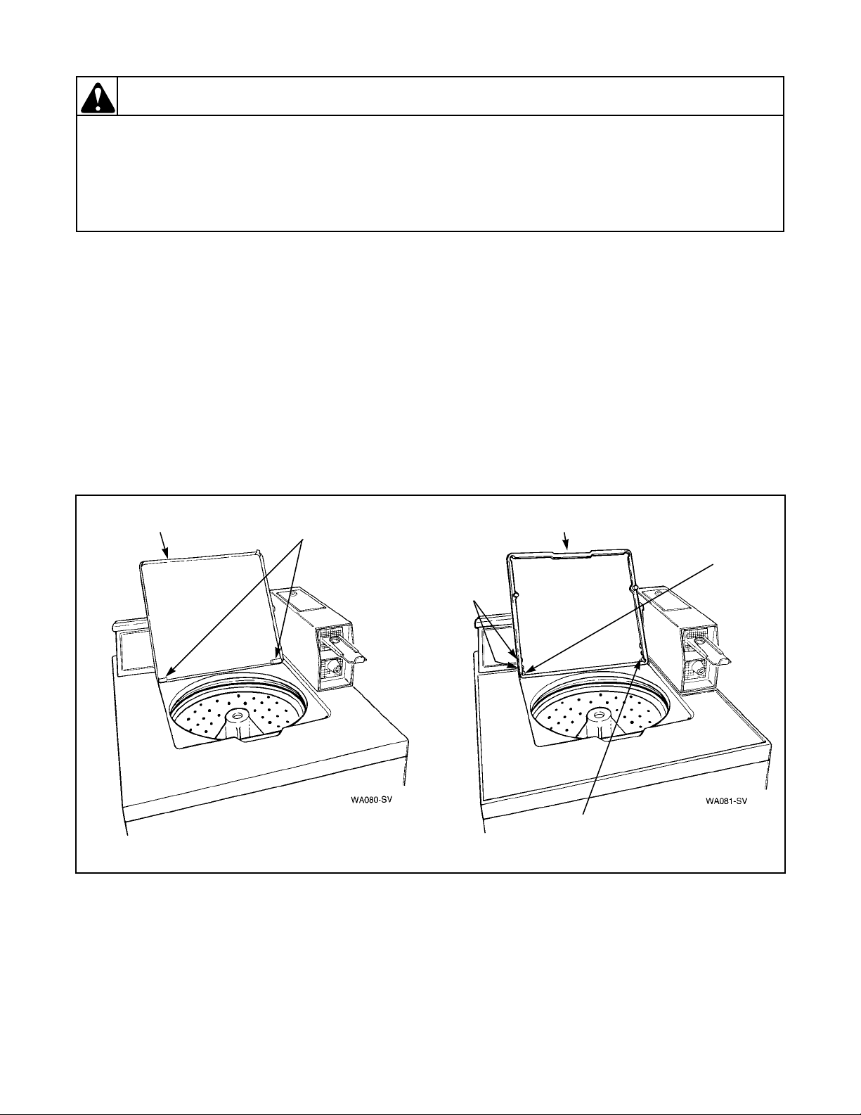
e. Through Serial No. R8237277YK – Remove
eight clips holding outer tub cover to tub. Refer
to Figure 40. Lift cover off tub and set beside
washer cabinet.
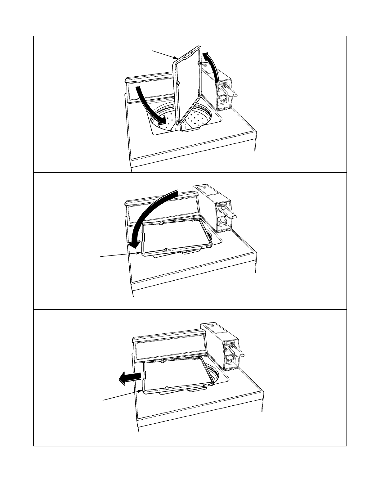
Starting Serial No. R8237278YK – There are
eight tub cover hold-down tabs which snap over
outer tub flange. Using the special tub cover
tool, Part No. 273P4, insert the two prongs of
the tool underneath each side of the tandem
tabs. Refer to Figure 40. Tilt the tool toward the
center of the tub cover and at the same time lift
upward on cover to unsnap hold-down tabs
from outer tub flange. One by one, disengage
each of the eight hold-down tabs from outer tub
flange and remove cover.
NOTE: Through Serial No. R8237277YK – When
installing the outer tub cover, always use a new
cover gasket. Lubricate the gasket with liquid soap
to aid in the assembly. Cover must be placed on the
outer tub so the notch on the top edge of the outer
tub cover is directly over the left front clip hole in
the tub. Refer to Figure 40. Starting with this hole,
place each spring clip in its respective hole and snap
in place. Refer to Figure 40 for proper clip
installation.
Starting Serial No. R8237278YK – When installing
outer tub cover, always use a new cover gasket.
Before installing the new gasket, clean and remove
any foreign material that is in the gasket groove of
the cover. The outer tub flange must also be cleaned.
Starting at the positioning pin that is located
between the two bleach drain tabs, lay gasket into
the gasket groove of the tub cover. Refer to
Figure 41. Using the semi-curled end of the tub
cover tool, Part No. 273P4, Figure 41, press against
both tabs when installing gasket past the ends of the
hold-down tabs and to bottom of groove. One by
one, insert gasket past tips of all eight down-down
tabs.
IMPORTANT: Care must be taken not to twist or
bunch the gasket in any one area as this will cause a
leak after assembly.
NOTE: Using your fingers, press gasket down into
gasket groove between the hold-down tabs. The tool
is designed to spread open the hold-down tabs thus
preventing tearing of the gasket during installation.
With the tub cover tilted at approximately a 45
degree angle, Figure 42, insert the positioning pin
on the tub cover into the notch on the outer tub
flange. The two bleach drain tabs must be angled
downward toward the inside wall of the outer tub.
This is required for proper dispensing of the bleach.
Lower the cover down and starting at the holddown tabs next to the positioning pin, push down
firmly on top of the tab area until hold-down tab
ends snap over edge of outer tub flange. This must
be done with all eight hold-down tabs to ensure a
water-tight seal between tub cover and outer tub
flange.
32918 37
© Copyright, Alliance Laundry Systems LLC – DO NOT COPY or TRANSMIT
Page 39

Section 5 Service Procedures
1/8 Inch
Clearance
Notch
Left Front
Clip Hole
THROUGH SERIAL NO. R8237277YK
Clip
Outer
Tub
Clips
(8)
Outer Tub
Cover
273P4
Tub Cover
Tool
Outer Tub
Cover
Hold-Down
Tabs
STARTING SERIAL NO. R8237278YK
Figure 40
38 32918
© Copyright, Alliance Laundry Systems LLC – DO NOT COPY or TRANSMIT
Page 40

Section 5 Service Procedures
WARNING
To reduce the risk of electric shock, fire, explosion, serious injury or death:
• Disconnect electric power to the washer before servicing.
• Never start the washer with any guards/panels removed.
• Whenever ground wires are removed during servicing, these ground wires must be
reconnected to ensure that the washer is properly grounded.
W003
The best assembly procedure is to start on one side,
then cross over to the opposite side. Continue with
this criss-cross pattern, until tub cover is fully
seated. Visually check each tab area again to ensure
that cover is seated.
Check whether or not the bleach drain tabs are in
the down position by looking through the two
square holes in the bleach funnel area of the tub
cover. If tabs are not down, a small screwdriver can
be inserted down through the holes in the bleach
funnel area and the tabs can be bent into position.
f. Remove the four screws and washers holding
washtub to the hub. Refer to Figure 43.
IMPORTANT: Porcelain Washtub Models — Use
care when tightening screws to avoid chipping
porcelain on washtub.
g. Lift washtub and lint filter or clothes guard out
of outer tub.
IMPORTANT: When removing washtub and lint
filter or clothes guard, DO NOT list up on the filter
or guard as your could damage it. Grasp top flange
of washtub and remove from outer tub.
Tub Cover
Gasket
Bleach
Drain Tabs
Hold-Down
Tabs
273P4
Tub Cover
Tool
NOTE: Be sure all traces of the old gasket are
removed from the bottom of the washtub. When
installing the washtub, always use a new gasket
between the tub and hub.
TO REMOVE LINT FILTER OR CLOTHES
GUARD FROM WASHTUB
a. Place a small screwdriver in behind slots
provided in the filter or guard. Refer to
Figure 43.
Press gasket into
groove using your
fingers.
Hold-Down
Tabs
b. Carefully pry pins of balance ring out of holes
in washtub. Refer to Figure 43.
Figure 41
NOTE: As you are prying out pins, lift up on the
filter or guard.
c. Pry the pins out of washtub holes
approximately half way around the tub before
the filter or guard can be removed.
32918 39
© Copyright, Alliance Laundry Systems LLC – DO NOT COPY or TRANSMIT
Page 41

Section 5 Service Procedures
Bleach Funnel
Area
Outer Tub
Cover
Outer
Tub
Bleach
Funnel
Outer
Tub
Cover
Gasket
Flange
Tub
Tub Cover
Hold-Down
Tabs
Bleach Drain
Tabs
Outer
Tub
Outer Tub
Cover
Bleach Drain
Tabs
Positioning Pin
(Viewed from
underside of
cover)
Tub Cover
Hold-Down
Tabs
Figure 42
40 32918
© Copyright, Alliance Laundry Systems LLC – DO NOT COPY or TRANSMIT
Page 42

Section 5 Service Procedures
WARNING
To reduce the risk of electric shock, fire, explosion, serious injury or death:
• Disconnect electric power to the washer before servicing.
• Never start the washer with any guards/panels removed.
• Whenever ground wires are removed during servicing, these ground wires must be
reconnected to ensure that the washer is properly grounded.
TO INSTALL LINT FILTER OR CLOTHES
GUARD IN WASHTUB
Place the filter or guard on top of washtub, making
sure the pins line up with holes in washtub. Then
carefully push the filter or guard down into the
washtub until all pins snap into their respective
holes.
WASHERS EQUIPPED WITH LINT FILTER
Washtub
Screws
Lint
Filter
Slots
W003
Pins
WASHERS EQUIPPED WITH CLOTHES GUARD
Washtub
Screws
Clothes
Guard
Slots
Pins
Figure 43
32918 41
© Copyright, Alliance Laundry Systems LLC – DO NOT COPY or TRANSMIT
Page 43

Section 5 Service Procedures
WARNING
To reduce the risk of electric shock, fire, explosion, serious injury or death:
• Disconnect electric power to the washer before servicing.
• Never start the washer with any guards/panels removed.
• Whenever ground wires are removed during servicing, these ground wires must be
reconnected to ensure that the washer is properly grounded.
W003
43. HUB AND SEAL KIT ASSEMBLY
IMPORTANT: If water is present in the washtub,
spin and pump out before removing the drive bell.
a. Remove two screws from bottom edge of front
panel. Refer to Figure 21.
b. Pull bottom of panel away from washer until
hold down clips (located on top flange of panel)
disengage from slots in cabinet top. Refer to
Figure 21.
c. Hinge or remove cabinet top. Refer to
Paragraph 39.
d. Remove the agitator. Refer to Paragraph 29.
e. Starting Serial No. R8237278YK – Unhook the
pressure hose from the retainer clips located on
the left rear edge of the outer tub cover. Refer to
Figure 39.
f. Disconnect filler hose from backflow
preventer. Refer to Figure 39.
NOTE: Through Serial No. R8237277YK – When
installing filler hose, white line on the hose must be
aligned with center line of the backflow preventer.
Refer to Figure 39. A one eighth inch clearance is
necessary to prevent the hose from rubbing on the
flange of the tub cover. Refer to Figure 40. Loosen
the hose clamp and move the hose to obtain the
proper clearance.
Starting Serial No. R8237278YK – When installing
filler hose, white dot on the hose must be aligned
with arrow on backflow preventer and white line on
hose that connects to tub cover must be aligned with
line located on top side of outer tub cover. Refer to
Figure 39. Make sure the hose is in its natural
position (not kinked or twisted). If it is not, loosen
hose clamp and straighten the hose.
g. Through Serial No. R8237277YK – Remove
eight clips holding outer tub cover to tub. Refer
to Figure 40.
Starting Serial No. R8237278YK – There are
eight tub cover hold-down tabs which snap over
outer tub flange. Using the special tub cover
tool, Part No. 273P4, insert the two prongs of
the tool underneath each side of the tandem
tabs. Refer to Figure 40. Tilt the tool toward the
center of the tub cover and at the same time lift
upward on cover to unsnap hold-down tabs
from outer tub flange. One by one, disengage
each of the eight hold-down tabs from outer tub
flange and remove cover.
h. Lift the cover off the outer tub and set beside
the washer cabinet.
i. Through Serial No. R8237277YK – Remove
old cover gasket from top of outer tub.
NOTE: Through Serial No. R8237277YK – When
installing the outer tub cover, always use a new
cover gasket. Lubricate the gasket with liquid soap
to aid in the assembly. Cover must be placed on the
outer tub so the notch on the top edge of the outer
tub cover is directly over the left front clip hole in
the tub. Refer to Figure 40. Starting with this hole,
place each spring clip in its respective hole and snap
in place. Refer to Figure 40 for proper clip
installation.
Starting Serial No. R8237278YK – When installing
outer tub cover, always use a new cover gasket.
Before installing the new gasket, clean and remove
any foreign material that is in the gasket groove of
the cover. The outer tub flange must also be cleaned.
Starting at the positioning pin that is located
between the two bleach drain tabs, lay gasket into
the gasket groove of the tub cover. Refer to
Figure 41. Using the semi-curled end of the tub
cover tool, Part No. 273P4, Figure 41, press against
both tabs when installing gasket past the ends of the
hold-down tabs and to bottom of groove. One by
one, insert gasket past tips of all eight down-down
tabs.
42 32918
© Copyright, Alliance Laundry Systems LLC – DO NOT COPY or TRANSMIT
Page 44

Section 5 Service Procedures
WARNING
To reduce the risk of electric shock, fire, explosion, serious injury or death:
• Disconnect electric power to the washer before servicing.
• Never start the washer with any guards/panels removed.
• Whenever ground wires are removed during servicing, these ground wires must be
reconnected to ensure that the washer is properly grounded.
W003
IMPORTANT: Care must be taken not to twist or
bunch the gasket in any one area as this will cause a
leak after assembly.
NOTE: Using your fingers, press gasket down into
gasket groove between the hold-down tabs. The tool
is designed to spread open the hold-down tabs thus
preventing tearing of the gasket during installation.
With the tub cover tilted at approximately a 45
degree angle, Figure 42, insert the positioning pin
on the tub cover into the notch on the outer tub
flange. The two bleach drain tabs must be angled
downward toward the inside wall of the outer tub.
This is required for proper dispensing of the bleach.
Lower the cover down and starting at the holddown tabs next to the positioning pin, push down
firmly on top of the tab area until hold-down tab
ends snap over edge of outer tub flange. This must
be done with all eight hold-down tabs to ensure a
water-tight seal between tub cover and outer tub
flange.
The best assembly procedure is to start on one side,
then cross over to the opposite side. Continue with
this criss-cross pattern, until tub cover is fully
seated. Visually check each tab area again to ensure
that cover is seated.
Check whether or not the bleach drain tabs are in
the down position by looking through the two
square holes in the bleach funnel area of the tub
cover. If tabs are not down, a small screwdriver can
be inserted down through the holes in the bleach
funnel area and the tabs can be bent into position.
IMPORTANT: When removing washtub and lint
filter or clothes guard, DO NOT list up on the filter
or guard as you could damage it. Grasp top flange
of washtub and remove from outer tub.
NOTE: Be sure all traces of the old gasket are
removed from the bottom of the washtub. When
installing the washtub, always use a new gasket
between the tub and hub.
TO REMOVE AGITATOR DRIVE BELL
a. Remove the screw and o-ring washer from top
side of drive bell.
NOTE: To remove drive bell from transmission
shaft will require using the No 294P4 Drive Bell
Tool. Refer to Figure 18.
b. Back bolt out of tool approximately three
quarters of the way.
c. Place tool over bell, making sure indent on
jaw lines up with the wide slots on bell. Refer
to Figure 19.
d. Screw bolt down through hole in top of bell
until bolt bottoms out in hole in transmission
shaft.
e. Place lip of each jaw under bottom edge of
drive bell, making sure indent on jaw lines up
with wide slots on bell. Then tighten two wing
nuts to hold jaws firmly against drive bell.
Refer to Figure 19.
f. Use an adjustable wrench and turn large nut on
tool COUNTERCLOCKWISE to pull drive
bell from transmission shaft. Refer to
Figure 20.
j. Remove the four screws and washers holding
washtub to the hub. Refer to Figure 43.
IMPORTANT: Porcelain Washtub Models — Use
care when tightening screws to avoid chipping
porcelain on washtub.
k. Lift washtub and lint filter or clothes guard out
of outer tub.
IMPORTANT: If large nut is turned clockwise
when pulling drive bell, you will twist off one
quarter inch bolt.
g. Turn the one quarter inch bolt out of the
transmission shaft, and remove tool and drive
bell from washer.
h. Loosen two wing nuts and remove drive bell
from tool.
i. Carefully pry the old seal out of the drive bell
and clean any foreign materials from the bell.
32918 43
© Copyright, Alliance Laundry Systems LLC – DO NOT COPY or TRANSMIT
Page 45

Section 5 Service Procedures
WARNING
To reduce the risk of electric shock, fire, explosion, serious injury or death:
• Disconnect electric power to the washer before servicing.
• Never start the washer with any guards/panels removed.
• Whenever ground wires are removed during servicing, these ground wires must be
reconnected to ensure that the washer is properly grounded.
W003
IMPORTANT: We recommend that both the seal
seat and the seal head be replaced together in pairs.
DO NOT replace only one of the two.
j. Install the new seal into the drive bell.
k. Remove the seal head from the hub and clean
any foreign material from the hub seal
mounting area.
l. Place the new seal head on hub and carefully
push the seal head into position.
IMPORTANT: Make sure the seal is pressed down
against the shoulder on the hub.
NOTE: Soapy water will aid in the assembly of the
seal onto the hub.
IMPORTANT: DO NOT apply any type of
lubricants to the sealing surfaces of either the seal
seat or seal head because you will damage the seals.
m. Remove large hex nut using a No. 306P4 Hex
Wrench. Refer to Figure 44.
n. Remove spline insert from transmission tube.
Refer to Figure 44.
IMPORTANT: Use a new spline insert each time
hex nut is removed. DO NOT reuse old insert
because hex nut may loosen during the operation.
o. Remove the hub from the splines on the
transmission tube.
NOTE: It may be necessary to use a gear puller to
remove the hub.
Transmission
Shaft
Hex
Hub
Assembly
Spline
Insert
Figure 44
Nut
a. Apply a small amount of No. 27615P Sealant
(supplied in kit) around outer surface of tub
flange. Refer to Figure 45.
IMPORTANT: DO NOT allow sealant to contact the
flinger because this could prevent the flinger from
keeping moisture out of upper bearing. Refer to
Figure 44.
b. Apply a light film of nonstaining petroleum
jelly (such as Vaseline®) to bronze portion of
water seal and to outer surface of stainless steel
sleeve. Refer to Figure 46.
p. Remove the old water seal from the outer tub.
IMPORTANT: Use care when removing the old seal
so as not to damage the tub flange or porcelain.
TO INSTALL NO. 495P3 HUB AND SEAL
KIT
IMPORTANT: Be sure the inner surface of the hub
flange is clean of all foreign material before
installing the new seal.
44 32918
© Copyright, Alliance Laundry Systems LLC – DO NOT COPY or TRANSMIT
IMPORTANT: DO NOT over lubricate!
c. Insert stainless steel sleeve into water seal from
bottom side of seal until sleeve is flush with
bronze portion of water seal. Refer to
Figure 46.
d. Leave garter spring on seal. Place new seal over
outer tub flange (with seal lip on outside of tub
flange). Then press seal into tub flange opening
using moderate finger pressure.
Page 46

Section 5 Service Procedures
WARNING
To reduce the risk of electric shock, fire, explosion, serious injury or death:
• Disconnect electric power to the washer before servicing.
• Never start the washer with any guards/panels removed.
• Whenever ground wires are removed during servicing, these ground wires must be
reconnected to ensure that the washer is properly grounded.
W003
e. Carefully apply a small amount of No. 27615P
Sealant (supplied in kit) around outer edge of
seal and tub. (The area located just below garter
spring. Refer to Figure 46.)
IMPORTANT: DO NOT allow sealant to contact
sealing surface of water seal because it will cause a
water leak.
f. Lubricate inner splines of new hub assembly
(supplied in kit) with No. 27604P Anti-Seize
Compound.
g. Carefully place new hub assembly on splined
transmission tube.
Outer Tub
Flange
IMPORTANT: Firmly push hub down against outer
tub seal and hold in this position.
h. While holding hub down, place new spline
insert (with fingers pointing upward) over
transmission tube until it bottoms against hub.
Then place hex nut on the transmission tube
(with larger inside bevel on nut toward spline
insert) then tighten nut.
IMPORTANT: Torque hex nut down between 40 to
70 foot-pounds (54.23 to 94.91 Nm). If torque
wrench is not available, tap hex wrench with a
hammer until hub turns or until nut will no longer
tighten.
Apply Bead of
No. 27615P
Sealant
(Step “a”)
Flinger
Figure 45
32918 45
© Copyright, Alliance Laundry Systems LLC – DO NOT COPY or TRANSMIT
Page 47

Section 5 Service Procedures
WARNING
To reduce the risk of electric shock, fire, explosion, serious injury or death:
• Disconnect electric power to the washer before servicing.
• Never start the washer with any guards/panels removed.
• Whenever ground wires are removed during servicing, these ground wires must be
reconnected to ensure that the washer is properly grounded.
W003
Stainless Steel
Insert Sleeve From
Bottom Side of Seal
Figure 46
Press Here
to Assemble
Garter
Spring
Apply Bead of
No. 27615P
Sealant Here
(Step “e”)
Water
Seal
Lubricate
(Step “b”)
i. Apply a small amount of nonstaining petroleum
jelly (such as Vaseline®) to each of the sealing
surfaces where washtub gasket will contact hub
and bottom of washtub.
j. Carefully place new washtub gasket (supplied
in kit) on hub.
NOTE: Be sure holes in gasket are aligned with bolt
holes in hub and that all traces of old gasket are
removed from bottom of washtub.
k. Install washtub by grasping top flange of
washtub and carefully lower washtub down
onto gasket and hub assembly.
IMPORTANT: Before setting tub into place, be sure
bolt holes in the washtub line up with holes in gasket
and hub.
l. Secure washtub to hub using four screws
previously removed.
IMPORTANT: Porcelain Washtub Models — Use
care when tightening cap screws to avoid chipping
porcelain on the washtub.
m. Through Serial No. R8237277YK – Carefully
place new outer tub cover gasket (supplied in
kit) around the top rim of outer tub.
Sleeve
Lubricate
(Step “b”)
Bronze Portion
of Seal
Flush
Garter
Spring
Apply Bead of
No. 27615P
Sealant Here
(Step “e”)
NOTE: Through Serial No. R8237277YK – When
installing the outer tub cover, lubricate the cover
gasket with liquid soap to aid assembly. Cover must
be placed on the outer tub so the notch on the top
edge of the outer tub cover is directly over the left
front clip hole in the tub. Refer to Figure 40.
Starting with this hole, place each spring clip in its
respective hole and snap it into place. Refer to
Figure 40 for proper clip installation.
Starting Serial No. R8237278YK – When installing
outer tub cover, always use a new cover gasket.
Before installing the new gasket, clean and remove
any foreign material that is in the gasket groove of
the cover. The outer tub flange must also be cleaned.
Starting at the positioning pin that is located
between the two bleach drain tabs, lay gasket into
the gasket groove of the tub cover. Refer to
Figure 41. Using the semi-curled end of the tub
cover tool, Part No. 273P4, Figure 41, press against
both tabs when installing gasket past the ends of
hold-down tabs and to bottom of groove. One by
one, insert gasket past tips of all eight hold-down
tabs.
46 32918
© Copyright, Alliance Laundry Systems LLC – DO NOT COPY or TRANSMIT
Page 48

Section 5 Service Procedures
WARNING
To reduce the risk of electric shock, fire, explosion, serious injury or death:
• Disconnect electric power to the washer before servicing.
• Never start the washer with any guards/panels removed.
• Whenever ground wires are removed during servicing, these ground wires must be
reconnected to ensure that the washer is properly grounded.
W003
IMPORTANT: Care must be taken not to twist or
bunch the gasket in any one area as this will cause a
leak after assembly.
NOTE: Using your fingers, press gasket down into
gasket groove between the hold-down tabs. The tool
is designed to spread open the hold-down tabs thus
preventing tearing of the gasket during installation.
With the tub cover tilted at approximately a 45
degree angle, Figure 42, insert the positioning pin
on the tub cover into the notch on the outer tub
flange. The two bleach drain tabs must be angled
downward toward the inside wall of the outer tub.
This is required for proper dispensing of the bleach.
Lower the cover down and starting at the holddown tabs next to the positioning pin, push down
firmly on top of the tab area until hold-down tab
ends snap over edge of outer tub flange. This must
be done with all eight hold-down tabs to ensure a
water-tight seal between tub cover and outer tub
flange.
The best assembly procedure is to start on one side,
then cross over to the opposite side. Continue with
this criss-cross pattern, until tub cover is fully
seated. Visually check each tab area again to ensure
that cover is seated.
Starting Serial No. R8237278YK – When reinstalling
filler hose, white dot on the hose must be aligned
with arrow on backflow preventer and white line on
hose that connects to tub cover must be aligned with
line located on top side of outer tub cover. Refer to
Figure 39. Make sure the hose is in its natural
position (not kinked or twisted) and is parallel to the
rear edge of the washer cabinet. If it is not, loosen
hose clamp and straighten the hose.
TO INSTALL DRIVE BELL AND NO. 39508P
SEAL KIT
a. Place new seal head (supplied in kit) onto hub.
then carefully push seal head into position.
Make sure seal is pressed down against
shoulder on hub.
NOTE: Soapy water will aid in assembly of seal onto
hub.
b. Install new seal seat (supplied in kit) into drive
bell.
c. Position drive bell over transmission shaft.
Rotate drive bell until splines on drive bell line
up with splines on transmission shaft.
d. Place No. 294P4 Bell Tool over top of bell.
Screw bolt into transmission shaft until it
bottoms out.
Check whether or not the bleach drain tabs are in
the down position by looking through the two
NOTE: It is not necessary to clamp the tool jaws on
drive bell during this operation.
square holes in the bleach funnel area of the tub
cover. If tabs are not down, a small screwdriver can
be inserted down through the holes in the bleach
funnel area and the tabs can be bent into position.
e. Use an adjustable wrench and turn large nut on
tool CLOCKWISE to force drive bell down
onto transmission shaft until bell bottoms out
on shaft.
n. Reinstall the filler hose on the backflow
preventer.
NOTE: Through Serial No. R8237277YK – When
reinstalling filler hose, white line on the hose must
be aligned with center line of the backflow
preventer. Refer to Figure 39. A one eighth inch
clearance is necessary to prevent the hose from
rubbing on the flange of the tub cover. Refer to
f. Turn bolt out of transmission shaft and remove
tool.
g. Install new screw and o-ring washer (supplied
in kit) in top of drive bell.
NOTE: Torque new screw down between 45 to 55
inch pounds (5 to 6.2 Nm). Over torque will
mushroom the plastic bell.
Figure 40. Loosen the hose clamp and move the hose
to obtain the proper clearance.
32918 47
© Copyright, Alliance Laundry Systems LLC – DO NOT COPY or TRANSMIT
Page 49

Section 5 Service Procedures
WARNING
To reduce the risk of electric shock, fire, explosion, serious injury or death:
• Disconnect electric power to the washer before servicing.
• Never start the washer with any guards/panels removed.
• Whenever ground wires are removed during servicing, these ground wires must be
reconnected to ensure that the washer is properly grounded.
W003
h. Place agitator on top of drive bell. Slowly rotate
agitator until fingers on underside of agitator
line up with large slots on drive bell.
i. A sharp blow on top of agitator, with palm of
your hand, will force agitator down onto drive
bell, allowing fingers on underside of agitator
to lock under bottom edge of drive bell.
NOTE: Do not push agitator onto drive bell any
further than necessary.
j. Reinstall cabinet top and secure to washer
cabinet using screws previously removed.
k. Reinstall front panel.
l. Place washer into final spin, close loading door,
start washer and let washtub spin for
approximately 30 seconds to one minute.
IMPORTANT: Step “l” is necessary to allow
petroleum jelly, applied to water seal, a change to
run in on seal surfaces before water is added to
washer.
44. OUTER TUB
a. Remove the agitator. Refer to Paragraph 29.
b. Remove the front panel. Refer to Paragraph 31.
c. Remove the two cabinet top hold-down screws
and hinge the cabinet top or remove. Refer to
Paragraph 39.
d. Loosen the hose clamp and disconnect the filler
hose from the backflow preventer. Refer to
Figure 39.
NOTE: Through Serial No. R8237277YK – When
reinstalling filler hose, white line on the hose must
be aligned with center line of the backflow
preventer. Refer to Figure 39. A one eighth inch
clearance is necessary to prevent the hose from
rubbing on the flange of the tub cover. Refer to
Figure 40. Loosen the hose clamp and move the hose
to obtain the proper clearance.
Starting Serial No. R8237278YK – When reinstalling
filler hose, white dot on the hose must be aligned
with arrow on backflow preventer and white line on
hose that connects to tub cover must be aligned with
line located on top side of outer tub cover. Refer to
Figure 39. Make sure the hose is in its natural
position (not kinked or twisted) and is parallel to the
rear edge of the washer cabinet. If it is not, loosen
hose clamp and straighten the hose.
e. Through Serial No. R8237277YK – Remove
eight clips holding cover to outer tub. Refer to
Figure 40.
Starting Serial No. R8237278YK – There are
eight tub cover hold-down tabs which snap over
outer tub flange. Using the special tub cover
tool, Part No. 273P4, insert the two prongs of
the tool underneath each side of the tandem
tabs. Refer to Figure 40. Tilt the tool toward the
center of the tub cover and at the same time lift
upward on cover to unsnap hold-down tabs
from outer tub flange. One by one, disengage
each of the eight hold-down tabs from outer tub
flange and remove cover.
f. Remove the cover from the outer tub and set off
to the side to avoid damage, then remove the
old gasket.
NOTE: Through Serial No. R8237277YK – When
installing the outer tub cover, always use a new
cover gasket. Lubricate the gasket with liquid soap
to aid in the assembly. Cover must be placed on the
outer tub so the notch on the top edge of the outer
tub cover is directly over the left front clip hole in
the tub. Refer to Figure 40. Starting with this hole,
place each spring clip in its respective hole and snap
in place. Refer to Figure 40 for proper clip
installation.
Starting Serial No. R8237278YK – When installing
outer tub cover, always use a new cover gasket.
Before installing the new gasket, clean and remove
any foreign material that is in the gasket groove of
the cover. The outer tub flange must also be cleaned.
Starting at the positioning pin that is located
between the two bleach drain tabs, lay gasket into
the gasket groove of the tub cover. Refer to
Figure 41. Using the semi-curled end of the tub
cover tool, Part No. 273P4, Figure 41, press against
both tabs when installing gasket past the ends of the
hold-down tabs and to bottom of groove. One by
48 32918
© Copyright, Alliance Laundry Systems LLC – DO NOT COPY or TRANSMIT
Page 50

Section 5 Service Procedures
WARNING
To reduce the risk of electric shock, fire, explosion, serious injury or death:
• Disconnect electric power to the washer before servicing.
• Never start the washer with any guards/panels removed.
• Whenever ground wires are removed during servicing, these ground wires must be
reconnected to ensure that the washer is properly grounded.
W003
one, insert gasket past tips of all eight down-down
tabs.
IMPORTANT: Care must be taken not to twist or
bunch the gasket in any one area as this will cause a
leak after assembly.
NOTE: Using your fingers, press gasket down into
gasket groove between the hold-down tabs. The tool
is designed to spread open the hold-down tabs thus
preventing tearing of the gasket during installation.
With the tub cover tilted at approximately a 45
degree angle, Figure 42, insert the positioning pin
on the tub cover into the notch on the outer tub
flange. The two bleach drain tabs must be angled
downward toward the inside wall of the outer tub.
This is required for proper dispensing of the bleach.
Lower the cover down and starting at the holddown tabs next to the positioning pin, push down
firmly on top of the tab area until hold-down tab
ends snap over edge of outer tub flange. This must
be done with all eight hold-down tabs to ensure a
water-tight seal between tub cover and outer tub
flange.
The best assembly procedure is to start on one side,
then cross over to the opposite side. Continue with
this criss-cross pattern, until tub cover is fully
seated. Visually check each tab area again to ensure
that cover is seated.
Check whether or not the bleach drain tabs are in
the down position by looking through the two
square holes in the bleach funnel area of the tub
cover. If tabs are not down, a small screwdriver can
be inserted down through the holes in the bleach
funnel area and the tabs can be bent into position.
IMPORTANT: When removing washtub and lint
filter or clothes guard, DO NOT lift up on the filter
or guard as your could damage it. Grasp top flange
of washtub and remove from outer tub.
i. Remove agitator drive bell. Refer to Paragraph
30.
j. Remove large hex nut using No. 306P4 Hex
Wrench. Then remove spline insert from
transmission tube.
IMPORTANT: Use a new spline insert each time the
hex nut is removed. DO NOT reuse the old insert as
hex nut may loosen during the washer operation.
k. Remove hub from splines on transmission tube.
NOTE: It may be necessary to use a gear puller to
remove hub.
l. Remove old water seal from outer tub.
IMPORTANT: Use care when removing old seal so
as not to damage tub flange or porcelain.
NOTE: When reinstalling or replacing outer tub,
always install a new No. 495P3 Hub and Seal Kit.
Refer to Paragraph 43.
m. Reach in through front of motor mounting
bracket and move idler lever to left to release
tension on belt.
IMPORTANT: Use care when releasing idler lever
tension. If idler lever spring, or helper spring, are
overstretched, washer operation will be affected.
n. While holding idler lever, reach in and around
right side of motor and run belt off right side of
pulley.
g. Remove the four screws and washers holding
washtub to the hub. Refer to Figure 43.
IMPORTANT: When removing or reinstalling
complete outer tub into washer (with transmission,
balance ring and pivot dome attached), damage
IMPORTANT: Porcelain Washtub Models — Use
care when tightening screws to avoid chipping
porcelain on washtub.
h. Lift washtub (with lint filter or clothes guard
attached) out of outer tub.
32918 49
© Copyright, Alliance Laundry Systems LLC – DO NOT COPY or TRANSMIT
could occur to idler lever if the idler spring and
helper spring are left hooked to the motor mounting
bracket.
With the idler spring and helper spring hooked to
motor mounting bracket, the idler lever extends out
Page 51

Section 5 Service Procedures
WARNING
To reduce the risk of electric shock, fire, explosion, serious injury or death:
• Disconnect electric power to the washer before servicing.
• Never start the washer with any guards/panels removed.
• Whenever ground wires are removed during servicing, these ground wires must be
reconnected to ensure that the washer is properly grounded.
W003
through rear of bracket. When removing or
reinstalling complete tub assembly, the idler lever is
in the way and can be damaged (bent), or idler
pulley could be chipped. A bent idler lever will
cause misalignment of the idler pulley with the drive
belt, and a chipped idler pulley will damage the belt.
We recommend that before removing or reinstalling
the complete tub assembly, you unhook the idler
spring and helper spring and move the idler lever
out of the way. This will prevent the possibility of
idler lever or pulley damage.
o. Using No. 321P4 Spring Hook Tool, unhook
five centering springs from lower edge of outer
tub. Refer to Figure 47.
IMPORTANT: When removing centering springs,
mark on side of outer tub what notch the spring was
hooked into. Springs must be placed in same notch
when reinstalling. Do not overstretch the springs.
Mark the word “FRONT” on front side of outer tub
so complete tub module can be reinstalled in same
position.
Notch
Centering
Spring
Figure 47
50 32918
© Copyright, Alliance Laundry Systems LLC – DO NOT COPY or TRANSMIT
Hose
Centering
Spring
Page 52

Section 5 Service Procedures
WARNING
To reduce the risk of electric shock, fire, explosion, serious injury or death:
• Disconnect electric power to the washer before servicing.
• Never start the washer with any guards/panels removed.
• Whenever ground wires are removed during servicing, these ground wires must be
reconnected to ensure that the washer is properly grounded.
W003
p. Disconnect hose between outer tub and pump
assembly.
q. Remove the hose clamp holding the pressure
hose to the pressure accumultor. Then remove
the tape holding the pressure hose to the outer
tub.
r. Grasp outer tub and lift complete tub assembly
(with transmission, balance ring and pivot
dome attached) straight up and out of washer
cabinet.
s. Turn outer tub upside-down and set on
protective padding.
t. Remove screws and lockwashers holding each
support leg to outer tub. Refer to Figure 48.
Then lift transmission, balance ring and pivot
dome off tub.
Brake
Assembly
Leg
Plate
NOTE: To prevent porcelain damage, leg plates
must be installed on both sides of outer tub flange
when reinstalling support legs. (The thinner plate
must be installed between leg and tub flange and the
thicker plate must be installed on outside of tub
flange.) Do not overtighten screws as this could
cause stripping or porcelain damage.
u. Turn outer tub upright and remove pressure
accumulator and grommet.
NOTE: When installing grommet into outer tub, the
thicker lip of grommet must be installed to outside
of tub. Lubricate outer surface of large opening of
accumulator with liquid soap to aid when
assembling accumulator into grommet.
Pivot
Dome
Drive
Pulley
Lower Bearing
Housing
Transmission
Assembly
Balance
Ring
Figure 48
32918 51
© Copyright, Alliance Laundry Systems LLC – DO NOT COPY or TRANSMIT
Screw and
Lockwasher
Page 53

Section 5 Service Procedures
WARNING
To reduce the risk of electric shock, fire, explosion, serious injury or death:
• Disconnect electric power to the washer before servicing.
• Never start the washer with any guards/panels removed.
• Whenever ground wires are removed during servicing, these ground wires must be
reconnected to ensure that the washer is properly grounded.
W003
45. DRIVE PULLEY AND HELIX
a. Remove two screws from bottom edge of front
panel. Refer to Figure 21.
b. Pull bottom of panel away from washer until
hold-down clips (located on top flange of
panel) disengage from slots in cabinet top.
Refer to Figure 21.
c. Remove two front mounting screws and loosen
rear mounting screw holding pump and bracket
to washer base. Refer to Figure 22. Pivot entire
pump assembly toward motor to loosen belt
tension.
d. Run belt off motor pulley, then remove belt
from pump pulley.
NOTE: After installing belt, adjust belt. Refer to
Paragraph 55.
e. Reach in through front of motor mounting
bracket and move idler lever to left to release
tension on belt.
IMPORTANT: Use care when releasing idler lever
tension. If idler spring, or helper spring, are
overstretched, washer operation will be affected.
f. While holding idler lever, reach in and around
right side of motor and run belt off right side of
large drive pulley. Refer to Figure 23.
g. Remove belt from motor pulley and pull belt
out through front of motor mounting bracket.
NOTE: When installing motor and mounting
bracket, the positioning tab on right side of
mounting bracket must be placed in positioning
hole in base. Mounting bracket must be shifted
toward rear of washer to its limit of travel within
the mounting bracket attaching screws.
j. Remove screw, washer and helix holding the
drive pulley to input shaft or transmission
assembly. Refer to Figure 49.
k. Remove drive pulley by tilting right side up and
slide pulley out between right front and rear tub
support legs.
IMPORTANT: The two large flat washers must be
in place between spring and drive pulley when
reassembling. Refer to Figure 50 for assembly
sequence.
NOTE: When reassembling, place a small amount
of No. 03200 Lubricant to top side of drive pulley
that will be contacting large flat washers. Lubricate
helix ramps with a lubricant. Refer to Figure 50.
Helix
IMPORTANT: When reinstalling belt, there is not
drive belt adjustment.
h. Disconnect motor wire harness from base wire
harness at disconnect blocks. Refer to
Figure 28.
i. Remove four screws holding motor and
mounting bracket to washer base. Refer to
Figure 24. Then lift complete assembly out of
washer.
52 32918
© Copyright, Alliance Laundry Systems LLC – DO NOT COPY or TRANSMIT
Cap
Screw
Drive
Pulley
Figure 49
Washer
Page 54

Section 5 Service Procedures
WARNING
To reduce the risk of electric shock, fire, explosion, serious injury or death:
• Disconnect electric power to the washer before servicing.
• Never start the washer with any guards/panels removed.
• Whenever ground wires are removed during servicing, these ground wires must be
reconnected to ensure that the washer is properly grounded.
W003
46. BRAKE ASSEMBLY
a. Remove drive pulley and helix. Refer to
Paragraph 45.
b. Using a right angle needle nose pliers, remove
spring from around lower transmission tube
(located inside brake assembly). Refer to
Figure 50.
NOTE: Remove spring by turning in a
counterclockwise direction (looking from lower end
of input shaft of transmission assembly).
c. Remove three screws holding brake pads,
rubber sleeves and brake assembly to lower
bearing housing. Refer to Figure 50. Then
remove brake assembly, pads and spacer off
bottom of transmission assembly.
IMPORTANT: When reinstalling brake assembly,
we recommend replacing the three brake pads. DO
NOT replace just the worn pads. Apply a small
amount of No. 26594P Silicone Lubricant to both
sides of each brake pad where it will contact the
brake assembly.
NOTE: Refer to Figure 50 for assembly sequence.
NOTE: Through Serial No. R8237277YK – When
reinstalling filler hose, white line on the hose must
be aligned with center line of the backflow
preventer. Refer to Figure 39. A one eighth inch
clearance is necessary to prevent the hose from
rubbing on the flange of the tub cover. Refer to
Figure 40. Loosen the hose clamp and move the hose
to obtain the proper clearance.
Starting Serial No. R8237278YK – When reinstalling
filler hose, white dot on the hose must be aligned
with arrow on backflow preventer and white line on
hose that connects to tub cover must be aligned with
line located on top side of outer tub cover. Refer to
Figure 39. Make sure the hose is in its natural
position (not kinked or twisted) and is parallel to the
rear edge of the washer cabinet. If it is not, loosen
hose clamp and straighten the hose.
f. Reach in through front of motor mounting
bracket and move idler lever to left to release
tension on belt.
IMPORTANT: Use care when releasing idler lever
tension. If idler lever spring and helper spring are
overstretched, washer operation will be affected.
IMPORTANT: When installing the spring, be sure
it is inserted into groove in large splines of lower
transmission tube. Use tool, No. 242P4, for installing
the spring.
g. While holding idler lever, reach in and around
right side of motor and run belt off right side of
large drive pulley. Refer to Figure 23.
h. Pull belt out toward front of washer.
47. LOWER BEARING HOUSING
a. Remove two screws from bottom edge of front
panel. Refer to Figure 21.
b. Pull bottom of panel away from washer until
hold-down clips (located on top flange of
panel) disengage from slots in cabinet top.
Refer to Figure 21.
c. Remove two cabinet top hold down screws, and
hinge cabinet top or remove. Refer to
Paragraph 39.
d. Remove agitator. Refer to Paragraph 29.
e. Disconnect filler hose from backflow
preventer. Refer to Figure 39.
32918 53
© Copyright, Alliance Laundry Systems LLC – DO NOT COPY or TRANSMIT
Page 55

Section 5 Service Procedures
Brake Pad Kit
(Kit includes three
Pads and Sleeves)
Sleeve
Bearing
Housing
Assembly
Bearing
Shoulder
Screw
Brake Assembly
(Starting Serial
No. R8237278YK)
Pulley
Assembly
Washer
Screw
Spring
Washer
Lubricant Here
Spacer
Brake Assembly
(Through Serial
No. R8237277YK)
Apply
Lubricant
Here
Apply
Helix
Pivot
Dome
Base
Assembly
Figure 50
54 32918
© Copyright, Alliance Laundry Systems LLC – DO NOT COPY or TRANSMIT
Page 56

Section 5 Service Procedures
WARNING
To reduce the risk of electric shock, fire, explosion, serious injury or death:
• Disconnect electric power to the washer before servicing.
• Never start the washer with any guards/panels removed.
• Whenever ground wires are removed during servicing, these ground wires must be
reconnected to ensure that the washer is properly grounded.
W003
IMPORTANT: When removing or reinstalling
complete outer tub into washer (with washtub,
transmission, balance ring and pivot dome
attached), damage could occur to idler lever if the
idler spring and helper spring are left hooked to the
motor mounting bracket.
With the idler spring and helper spring hooked to
motor mounting bracket, the idler lever extends out
through rear of bracket. When removing or
reinstalling complete tub assembly, the idler lever is
in the way and can be damaged (bent), or idler
pulley could be chipped. A bent idler lever will
cause misalignment of the idler pulley with the drive
belt, and a chipped idler pulley will damage the belt.
We recommend that before removing or reinstalling
the complete tub assembly, you unhook the idler
spring and helper spring and move the idler lever
out of the way. This will prevent the possibility of
idler lever or pulley damage.
i. Using No. 321P4 Spring Hook Tool, unhook
five centering springs from lower edge of outer
tub. Refer to Figure 47.
IMPORTANT: When removing centering springs,
mark on side of outer tub what notch the spring was
hooked into. Springs must be placed in same notch
when reinstalling. Do not overstretch the springs.
Mark the word “FRONT” on front side of outer tub
so complete tub module can be reinstalled in same
position.
j. Disconnect hose between outer tub and pump
assembly.
IMPORTANT: Some water will always remain in
outer tub. Therefore, before removing hoses from
pump, pinch off or drain hoses to prevent water
spilling on floor.
k. Remove hose clamp holding the pressure hose
to the pressure accumultor and remove hose.
Then remove the tape holding the pressure hose
to the outer tub.
l. Grasp outer tub and lift tub (with washtub,
transmission, balance ring and pivot dome
attached) straight up and out of washer cabinet.
m. Turn the complete tub assembly upside-down
on protective padding.
IMPORTANT: Through Serial No. R8237277YK –
When turning complete tub assembly upside-down,
be careful not to damage the out-of-balance switch
trigger (located on outer tub cover).
n. Remove screw, washer and helix holding drive
pulley to transmission shaft. Refer to Figure 49.
o. Remove drive pulley from transmission shaft.
Remove Figure 49.
p. Remove two large flat washers from
transmission shaft. Refer to Figure 49.
q. Use a right angle needle nose pliers and remove
spring from around lower transmission tube
(located inside brake assembly).
NOTE: Remove spring by turning in a
counterclockwise direction (looking at bottom end
of shaft).
IMPORTANT: When installing spring, be sure it is
inserted into groove in large splines of lower
transmission tube. Use spring tool, No. 242P4, for
installing spring.
r. Remove three screws and rubber sleeves
holding brake pads to lower bearing housing.
Refer to Figure 50.
s. Lift brake assembly, pads and spacer off
transmission tube.
t. Remove three screws holding lower bearing
housing to tub support legs. Refer to Figure 50.
u. Rotate bearing housing past legs, then carefully
lift bearing housing off transmission tube.
NOTE: It may be necessary to loosen one leg from
pivot dome to rotate housing. It may require
tapping lightly on housing to loosen it from
transmission tube.
IMPORTANT: When installing lower bearing
housing, apply No. 27604P Anti-Seize Compound to
area of transmission tube that will be contacting
bearing. Refer to Figure 51.
32918 55
© Copyright, Alliance Laundry Systems LLC – DO NOT COPY or TRANSMIT
Page 57

Section 5 Service Procedures
WARNING
To reduce the risk of electric shock, fire, explosion, serious injury or death:
• Disconnect electric power to the washer before servicing.
• Never start the washer with any guards/panels removed.
• Whenever ground wires are removed during servicing, these ground wires must be
reconnected to ensure that the washer is properly grounded.
W003
Marked Side of
Balance Ring
Apply Anti-Seize
Compound to this
area of both the
upper and lower
transmission tubes.
TO REMOVE THE BEARING
a. Support bearing housing around outside
diameter of bearing opening and carefully press
bearing out of housing.
b. Clean all foreign material from inside diameter
of bearing opening.
c. Clean any foreign material from outside
diameter of new bearing.
d. Apply a retaining compound (such as Loctite)
to outside diameter of new bering and carefully
press new bearing into housing (with sealed
side facing up).
IMPORTANT: Press new bearing into housing by
pressing on outer race of bearing, press until
bearing bottoms out in housing.
48. TRANSMISSION ASSEMBLY
a. Remove two screws from bottom edge of front
panel. Refer to Figure 21.
Balance
Ring
Rack Area of
Transmission
Transmission
Assembly
Figure 51
b. Pull bottom of panel away from washer until
hold-down clips (located on top flange of
panel) disengage from slots in cabinet top.
Refer to Figure 21.
c. Remove two cabinet top hold-down screws,
Figure 28, and hinge cabinet top or remove,
Paragraph 39.
d. Loosen hose clamp, and disconnect filler hose
from backflow preventer. Refer to Figure 39.
NOTE: Through Serial No. R8237277YK – When
reinstalling filler hose, white line on the hose must
be aligned with center line of the backflow
preventer. Refer to Figure 39. A one eighth inch
clearance is necessary to prevent the hose from
rubbing on the flange of the tub cover. Refer to
Figure 39. Loosen the hose clamp and move the hose
to obtain the proper clearance.
Starting Serial No. R8237278YK – When reinstalling
filler hose, white dot on the hose must be aligned
56 32918
© Copyright, Alliance Laundry Systems LLC – DO NOT COPY or TRANSMIT
Page 58

Section 5 Service Procedures
WARNING
To reduce the risk of electric shock, fire, explosion, serious injury or death:
• Disconnect electric power to the washer before servicing.
• Never start the washer with any guards/panels removed.
• Whenever ground wires are removed during servicing, these ground wires must be
reconnected to ensure that the washer is properly grounded.
W003
with arrow on backflow preventer and white line on
hose that connects to tub cover must be aligned with
line located on top side of outer tub cover. Refer to
Figure 39. Make sure the hose is in its natural
position (not kinked or twisted) and is parallel to the
rear edge of the washer cabinet. If it is not, loosen
hose clamp and straighten the hose.
e. Through Serial No. R8237277YK – Remove
eight clips holding outer tub cover to tub. Refer
to Figure 40. Remove cover from outer tub and
set off to side of washer to avoid damage, then
remove old cover gasket.
NOTE: Through Serial No. R8237277YK – When
installing the outer tub cover, always use a new
cover gasket. Lubricate the gasket with liquid soap
to aid in the assembly. Cover must be placed on the
outer tub so the notch on the top edge of the outer
tub cover is directly over the left front clip hole in
the tub. Refer to Figure 40. Starting with this hole,
place each spring clip in its respective hole and snap
in place. Refer to Figure 40 for proper clip
installation.
Starting Serial No. R8237278YK – There are eight
tub cover hold-down tabs which snap over the outer
tub flange. Using the special tub cover tool, Part
No. 273P4, insert the two prongs of the tool
underneath each side of the tandem tabs. Refer to
Figure 40. Tilt the tool toward the center of the tub
cover and at the same time lift upward on cover to
unsnap hold-down tabs from outer tub flange. One
by one, disengage each of the eight hold-down tabs
from the outer tub flange and remove cover.
Starting Serial No. R8237278YK – When installing
outer tub cover, always use a new cover gasket.
Before installing the new gasket, clean and remove
any foreign material that is in the gasket groove of
the cover. The outer tub flange must also be cleaned.
Starting at the positioning pin that is located
between the two bleach drain tabs, lay gasket into
the gasket groove of the tub cover. Refer to
Figure 41. Using the semi-curled end of the tub
cover tool, Part No. 273P4, press against both tabs
when installing gasket past the ends of the holddown tabs and to bottom of groove. Refer to
Figure 41. One by one, insert gasket past tips of all
eight down-down tabs.
IMPORTANT: Care must be taken not to twist or
bunch the gasket in any one area as this will cause a
leak after assembly.
NOTE: Using your fingers, press gasket down into
gasket groove between the hold-down tabs. The tool
is designed to spread open the hold-down tabs thus
preventing tearing of the gasket during installation.
With the tub cover tilted at approximately a 45
degree angle, Figure 42, insert the positioning pin
on the tub cover into the notch on the outer tub
flange. The two bleach drain tabs must be angled
downward toward the inside wall of the outer tub.
This is required for proper dispensing of the bleach.
Lower the cover down and starting at the holddown tabs next to the positioning pin, push down
firmly on top of the tab area until hold-down tab
ends snap over edge of outer tub flange. This must
be done with all eight hold-down tabs to ensure a
water-tight seal between tub cover and outer tub
flange.
The best assembly procedure is to start on one side,
then cross over to the opposite side. Continue with
this criss-cross pattern, until tub cover is fully
seated. Visually check each tab area again to ensure
that cover is seated.
Check whether or not the bleach drain tabs are in
the down position by looking through the two
square holes in the bleach funnel area of the tub
cover. If tabs are not down, a small screwdriver can
be inserted down through the holes in the bleach
funnel area and the tabs can be bent into position.
f. Remove the four screws and washers holding
washtub to the hub. Refer to Figure 43.
IMPORTANT: Porcelain Washtub Models — Use
care when tightening screws to avoid chipping
porcelain on washtub.
32918 57
© Copyright, Alliance Laundry Systems LLC – DO NOT COPY or TRANSMIT
Page 59

Section 5 Service Procedures
WARNING
To reduce the risk of electric shock, fire, explosion, serious injury or death:
• Disconnect electric power to the washer before servicing.
• Never start the washer with any guards/panels removed.
• Whenever ground wires are removed during servicing, these ground wires must be
reconnected to ensure that the washer is properly grounded.
W003
g. Lift washtub and lint filter or clothes guard out
of outer tub.
IMPORTANT: When removing washtub, DO NOT
lift up on the filter or clothes guard as you could
damage it. Grasp top flange of washtub and remove
from outer tub.
h. Remove drive bell. Refer to Paragraph 30,
steps “a” through “k.”
i. Remove hex nut using No. 306P4 Hex Wrench.
j. Remove hub from splines on transmission tube.
NOTE: It may be necessary to use a gear puller to
remove hub.
k. Remove old water seal from outer tub.
IMPORTANT: Use care when removing old water
seal so as not to damage tub flange or porcelain.
NOTE: When reinstalling or replacing outer tub,
we recommend installing a new No. 495P3 Hub and
Seal Kit. Refer to Paragraph 43.
l. Reach in through front of motor mounting
bracket and move idler lever to left to release
tension on belt.
IMPORTANT: Use care when releasing idler lever
tension. If idler lever spring and helper spring are
overstretched, washer operation will be affected.
m. While holding idler lever, reach in and around
right side of motor and run belt off right side of
large drive pulley.
IMPORTANT: When removing or reinstalling
complete outer tub into washer (with transmission,
balance ring and pivot dome attached), damage
could occur to idler lever if the idler spring and
helper spring are left hooked to the motor mounting
bracket.
With the idler spring and helper spring hooked to
motor mounting bracket, the idler lever extends out
through rear of bracket. When removing or
reinstalling complete tub assembly, the idler lever is
in the way and can be damaged (bent), or idler
pulley could be chipped. A bent idler lever will
cause misalignment of the idler pulley with the drive
belt, and a chipped idler pulley will damage the belt.
We recommend that before removing or reinstalling
the complete tub assembly, you unhook the idler
spring and helper spring and move the idler lever
out of the way. This will prevent the possibility of
idler lever or pulley damage.
n. Using No. 321P4 Spring Hook Tool, unhook
five centering springs from lower edge of outer
tub. Refer to Figure 47.
IMPORTANT: When removing centering springs,
mark on side of outer tub what notch the spring was
hooked into. Springs must be placed in same notch
when reinstalling. Do not overstretch the springs.
Mark the word “FRONT” on front side of outer tub
so complete tub module can be reinstalled in same
position.
o. Disconnect hose between outer tub and pump
assembly.
IMPORTANT: Some water will always remain in
outer tub. Therefore, before removing hoses from
pump, pinch off or drain hoses to prevent water
spilling on floor.
p. Remove pressure hose from pressure
accumulator. Then remove tape holding the
pressure hose to the outer tub.
q. Grasp outer tub and lift complete tub assembly
(with transmission, balance ring and pivot
dome attached) straight up and out of washer
cabinet.
r. Turn outer tub upside-down and set on
protective padding.
s. Remove screw, washer and helix holding drive
pulley to transmission shaft. Then remove drive
pulley and large flat washer(s) from
transmission.
t. Using a right angle needle nose pliers, remove
the spring from around lower transmission tube
(located inside brake assembly).
58 32918
© Copyright, Alliance Laundry Systems LLC – DO NOT COPY or TRANSMIT
Page 60

Section 5 Service Procedures
WARNING
To reduce the risk of electric shock, fire, explosion, serious injury or death:
• Disconnect electric power to the washer before servicing.
• Never start the washer with any guards/panels removed.
• Whenever ground wires are removed during servicing, these ground wires must be
reconnected to ensure that the washer is properly grounded.
W003
NOTE: Remove spring by turning in a
counterclockwise direction (looking at bottom end
of shaft).
IMPORTANT: When reinstalling spring, be sure it
is inserted into groove in large spline of
transmission tube. Use spring tool, No. 242P4, for
installing spring.
u. Remove screws and lockwashers holding each
support leg to outer tub. Refer to Figure 48.
Then lift pivot dome, brake assembly and lower
bearing housing off transmission tube.
NOTE: It may be necessary to tap lightly on bearing
housing to loosen it from transmission tube.
IMPORTANT: When installing lower bearing
housing, pivot dome and brake assembly, apply No.
27604P Anti-Seize Compound to area of
transmission tube that will be contacting bearing.
Refer to Figure 51.
To prevent porcelain damage, leg plates must be
installed on both sides of outer tub flange when
reinstalling support legs. (The thinner plate must be
installed between leg and tub flange and the thicker
plate must be installed on outside of tub flange.) Do
not overtighten screws as this could cause stripping
or porcelain damage.
v. Remove four screws and lockwashers holding
the transmission assembly to balance ring.
w. Lift transmission assembly straight up and out
of balance ring and upper bearing.
IMPORTANT: When replacing or reinstalling
transmission assembly, it is important that
No. 27604P Anti-Seize Compound be applied to
area of the transmission tubes where they will be
contacting upper and lower bearings. Refer to
Figure 51.
When reinstalling transmission assembly, note
there is a mark located on outer edge of balance
ring. This mark indicates heavy side of ring. This
heavy side must be installed opposite the rack of the
transmission assembly. Refer to Figure 51.
Carefully lower transmission through balance ring
and upper bearing. DO NOT DROP OR LOWER
TRNASMISSION ASSEMBLY INTO POSITION
TOO HARD. This can cause the bearing to move
within the bearing housing which will cause
vibration, noise, wear or no spin.
TO DISASSEMBLE TRANSMISSION
ASSEMBLY
(Refer to Figure 52 for assembly sequence)
a. Place transmission in a vise with input shaft end
up. Clamp only the case, not the shaft.
NOTE: Supporting transmission in this manner will
allow oil to collect in the transmission case.
b. Before disassembling transmission halves,
mark outer edge of transmission case and cover
so two can be reassembled in the same position.
c. Place transmission in vise so three of the eight
screws holding transmission case and cover
together are in the twelve, four and seven
o’clock positions.
d. Loosen three screws, mentioned in step “c”,
approximately two turns. DO NOT remove
these three screws at this time. Remove
remaining five screws and lockwashers
completely.
e. Remove transmission assembly from vise.
f. While holding transmission by cover end,
gently tap each of the three remaining screws
until two halves separate. Place assembly back
into vise (cover end up) and remove three
screws and lockwashers.
g. Remove screw and washer holding reduction
gear to transmission cover and remove gear.
h. Remove special screw, lockwasher and flat
washer holding drive pinion to input shaft.
NOTE: To prevent input shaft from turning during
removal of special screw, place a helix onto shaft
and hold helix with a locking pliers.
i. Remove drive pinion from input shaft using a
hammer and punch to drive shaft out of pinion.
j. Remove input shaft and square washer from
transmission cover.
32918 59
© Copyright, Alliance Laundry Systems LLC – DO NOT COPY or TRANSMIT
Page 61

Section 5 Service Procedures
Retainer
Ring
Shaft
(Output)
Washer
Transmission
Case Assembly
Agitator
Pinion
Screw
Washer
Reduction
Gear
Transmission
Oil
(1 Fill)
Internal
Gear
Special Screw
Lockwasher
Washer
Drive
Pinion
Shaft
(Input)
Identification
Groove
Washer
(if present)
Dowel
Pin
Cap
Screw
(Use as a sealant between
Loctite
Transmission Case and Cover)
Rack
Slide
Transmission
Cover Assembly
Dowel
Pin
Figure 52
60 32918
© Copyright, Alliance Laundry Systems LLC – DO NOT COPY or TRANSMIT
Page 62

Section 5 Service Procedures
WARNING
To reduce the risk of electric shock, fire, explosion, serious injury or death:
• Disconnect electric power to the washer before servicing.
• Never start the washer with any guards/panels removed.
• Whenever ground wires are removed during servicing, these ground wires must be
reconnected to ensure that the washer is properly grounded.
W003
IMPORTANT: Carefully examine area inside cover
tube (seals, bearing, roller clutch, etc.). If oil is
present between seals and bearing, or roller clutch
is bad, it will require replacing complete
transmission cover assembly. The individual
components are not available separately.
k. Remove internal gear, slide and rack from
transmission case.
l. Remove transmission case from vise and drain
oil.
m. Remove retainer ring from output shaft.
n. Using a hammer and punch, carefully drive
shaft out of agitator pinion.
o. Carefully remove output shaft and washer from
transmission case.
IMPORTANT: Carefully examine area inside
transmission case tube (seals, bearings, etc.). If oil is
present between seals and bearings, it will require
replacing complete transmission case. Seals and
bearings are not available separately.
TO REASSEMBLE TRANSMISSION
ASSEMBLY
IMPORTANT: Wash all the individual components
in a cleaning solution (mineral spirits). Wipe inside
of transmission case and cover with a clean cloth,
dampened with cleaning solution, to remove any
impurities. DO NOT allow cleaning solution to come
in contact with bearings and seals in transmission
case and/or cover.
a. Carefully insert output shaft and washer into
transmission case.
b. Place agitator pinion on splines of output shaft
and press onto shaft.
c. Install retainer ring on output shaft.
d. Place transmission case into a vise. Clamp only
the case, not the shaft.
e. Place rack inside transmission case with rack
resting on bar in case. Agitator pinion must
engage the rack.
NOTE: Put a light film of transmission oil on bar
where rack will slide back and forth.
f. Position slide in slot in rack.
NOTE: Put a light film of transmission oil in slot on
rack. Transmission oil should be put in track of
transmission case where internal gear will ride.
g. Place internal gear into transmission case.
Make sure guide pin on internal gear fits in hole
in slide.
IMPORTANT: Never install a used internal gear in
a new transmission case. If transmission case and
internal gear are to be reused, be sure they are used
as the original set.
h. Refill transmission case with new No. 27243P
Transmission Oil (one fill).
i. To prevent seal damage, insert input shaft into
cover starting at outer end of cover tube.
IMPORTANT: End of shaft with identification
groove must be facing outward. Refer to Figure 52.
This is the end that will mate with the helix.
j. Place the square washer (if present) over shaft
and into position within the cover.
k. Install drive pinion, flat washer, lockwasher
and special screw onto input shaft.
NOTE: Use a thread locking compound on threads
of special screw to prevent screw from loosening on
shaft.
IMPORTANT: Make sure mating surfaces of
transmission cover and case are free of oil or any
other foreign material.
l. Place reduction gear on stub shaft of cover and
install screw and washer.
NOTE: Use a thread locking compound on threads
of special screw to prevent screw from loosening on
shaft.
m. Apply a bead of sealant, No. 37577P Loctite, on
mating surface of transmission case.
IMPORTANT: Bead of sealant should be no more
than one sixteenth inch in diameter. DO NOT allow
any sealant to contact edges of internal gear (sealant
may damage moving parts).
32918 61
© Copyright, Alliance Laundry Systems LLC – DO NOT COPY or TRANSMIT
Page 63

Section 5 Service Procedures
WARNING
To reduce the risk of electric shock, fire, explosion, serious injury or death:
• Disconnect electric power to the washer before servicing.
• Never start the washer with any guards/panels removed.
• Whenever ground wires are removed during servicing, these ground wires must be
reconnected to ensure that the washer is properly grounded.
W003
n. Carefully place transmission cover over top of
transmission case. Make sure holes in cover
line up with holes in case, and marked edges of
two halves are aligned.
o. Carefully lower cover onto case.
p. Secure two transmission halves together, using
eight screws removed during disassembly.
Tighten eight screws evenly.
q. Remove complete transmission assembly from
vise.
r. Apply Anti-Seize compound, No. 27604P, to
smooth area of both transmission tubes that will
be contacting upper and lower bearings.
49. BALANCE RING
a. Remove transmission assembly. Refer to
Paragraph 48, steps “a” through “w”.
b. Lift balance ring off outer tub.
IMPORTANT: When reinstalling balance ring, note
there is a mark located on the outer edge of the
balance ring. This mark indicates the heavy side of
ring. This heavy side must be installed opposite the
rack of the transmission assembly. Refer to
Figure 51.
50. UPPER BEARING ASSEMBLY
a. Remove transmission assembly. Refer to
Paragraph 48, steps “a” through “w”.
b. Remove screws and lockwashers holding each
support leg to outer tub. Refer to Figure 48. Lift
complete pivot dome (with drive pulley, brake
assembly, lower bearing housing, transmission
assembly and balance ring attached) off outer
tub.
IMPORTANT: To prevent porcelain damage, leg
plates must be installed on both sides of outer tub
flange when reinstalling support legs. (The thinner
plate must be installed between the leg and tub
flange and the thicker plate must be installed on the
outside of the tub flange.) Do not overtighten screws
as this could cause stripping or porcelain damage.
c. Remove three screws holding upper bearing
and housing to bottom of outer tub. Refer to
Figure 53.
NOTE: Replace bearing and housing as an
assembly and be sure flinger is properly positioned
between the outer tub and bearing assembly. Refer
to Figure 53.
Cap
Ball
Bearing
Flinger
Upper
Bearing
Housing
62 32918
© Copyright, Alliance Laundry Systems LLC – DO NOT COPY or TRANSMIT
Outer
Tub
Upper
Bearing
Housing
Figure 53
Screw
Flinger
Page 64

Section 5 Service Procedures
WARNING
To reduce the risk of electric shock, fire, explosion, serious injury or death:
• Disconnect electric power to the washer before servicing.
• Never start the washer with any guards/panels removed.
• Whenever ground wires are removed during servicing, these ground wires must be
reconnected to ensure that the washer is properly grounded.
W003
1-7/16"
51. SNUBBER PADS
a. Remove transmission assembly. Refer to
Paragraph 48, steps “a” through “r”.
b. Scrape old snubber pads from washer base.
c. Thoroughly clean area of washer base where
new snubber pads will be installed.
NOTE: Use a cleaning agent, such as lacquer
thinner, for removing grease, old adhesive, or any
foreign materials from washer base.
1/16"
Figure 54
IMPORTANT: The top edge of the snubber pads
should be one and seven sixteenth inches from lower
part of dome with a distance of one sixteenth inch
between pads. Refer to Figure 54.
IMPORTANT: Before proceeding, allow pads to
adhere to washer base for approximately 30
minutes.
Dome Area of
Washer Base
TO INSTALL THE NO. 434P3 SNUBBER
PAD KIT
a. Brush approximately a three quarter inch wide
strip of No. 510704P Adhesive to dome area of
washer base where new pads will be applied.
IMPORTANT: Do not allow adhesive to get on
surface of new pads that will be contacting the pivot
dome of the tub module.
b. Carefully align and apply new snubber pads
with the fluffed side against base dome so they
Pivot
Dome
Washer Base
Dome Recess
are equally spaced. Refer to Figure 54.
Figure 55
32918 63
© Copyright, Alliance Laundry Systems LLC – DO NOT COPY or TRANSMIT
Page 65

Section 5 Service Procedures
WARNING
To reduce the risk of electric shock, fire, explosion, serious injury or death:
• Disconnect electric power to the washer before servicing.
• Never start the washer with any guards/panels removed.
• Whenever ground wires are removed during servicing, these ground wires must be
reconnected to ensure that the washer is properly grounded.
W003
Notch
Centering
Spring
(5)
THROUGH SERIAL NO. R8237277YK
(Wire Harness
must be installed
ahead of spring)
Notch
Centering
Spring
(5)
STARTING SERIAL NO. R8237278YK
Figure 56
Drive
Pulley
Idler
Lever
Helper
Spring
Back
Hole
Idler
Spring
Hook Spring
Here
Drive
Belt
Motor
Attaching
Screws
Figure 57
64 32918
© Copyright, Alliance Laundry Systems LLC – DO NOT COPY or TRANSMIT
Page 66

Section 5 Service Procedures
WARNING
To reduce the risk of electric shock, fire, explosion, serious injury or death:
• Disconnect electric power to the washer before servicing.
• Never start the washer with any guards/panels removed.
• Whenever ground wires are removed during servicing, these ground wires must be
reconnected to ensure that the washer is properly grounded.
W003
c. Apply a liberal amount of No. 26594P Silicone
Lubricant to surface of the new pads that will
contact pivot dome.
d. Carefully place tub module back into washer
making sure pivot dome is positioned properly
in the dome recess of washer base. Refer to
Figure 55.
NOTE: Be sure the word “FRONT” (on outer tub)
is facing toward front of washer.
e. Use No. 321P4 Spring Hook Tool and, starting
with rear springs, hook five centering springs
into lower edge of outer tub.
NOTE: Through Serial No. R8237277YK – Springs
must be hooked into the center of the three notches.
Refer to Figure 56.
Starting Serial No. R8237278YK – Springs must be
hooked in the top of the two notches.
f. Connect hose from outer tub to pump and
tighten hose clamp.
g. Reconnect idler spring to the clip on motor
mounting bracket, and the helper spring into
back hole in mounting bracket. Refer to
Figure 57.
h. Place drive belt on motor pulley, reach around
right side of motor, starting with belt on right
side of large pulley, run belt onto large pulley.
i. Route the pressure hose as shown in Figure 58.
Then route the pressure hose back up through
the hole in the cabinet top.
j. Reconnect filler hose to backflow preventer.
Refer to Figure 39.
NOTE: Through Serial No. R8237277YK – When
installing filler hose, white line on the hose must be
aligned with center line of the backflow preventer.
Refer to Figure 39. A one eighth inch clearance is
necessary to prevent the hose from rubbing on the
flange of the tub cover. Refer to Figure 40. Loosen
the hose clamp and move the hose to obtain the
proper clearance.
Starting Serial No. R8237278YK – When installing
filler hose, white dot on the hose must be aligned
with arrow on backflow preventer and white line on
hose that connects to tub cover must be aligned with
line located on top side of outer tub cover. Refer to
Figure 39. Make sure the hose is in its natural
position (not kinked or twisted) and is parallel to the
rear edge of the washer cabinet. If it is not, loosen
hose clamp and straighten the hose.
k. Reinstall cabinet top.
l. Remove control panel, reconnect pressure hose
to pressure switch. Then reinstall control panel.
m. Reinstall washer front panel.
n. Reconnect washer power cord and open water
supply valves.
(continued)
32918 65
© Copyright, Alliance Laundry Systems LLC – DO NOT COPY or TRANSMIT
Page 67

Section 5 Service Procedures
WARNING
To reduce the risk of electric shock, fire, explosion, serious injury or death:
• Disconnect electric power to the washer before servicing.
• Never start the washer with any guards/panels removed.
• Whenever ground wires are removed during servicing, these ground wires must be
reconnected to ensure that the washer is properly grounded.
NOTE: Washer must be run through a complete
cycle to make sure it is operating properly.
Pressure
Pressure
Hose
Hose
W003
THROUGH SERIAL NO. R8237277YK
STARTING SERIAL NO. R8237278YK
Figure 58
66 32918
© Copyright, Alliance Laundry Systems LLC – DO NOT COPY or TRANSMIT
Page 68

Section 6
Adjustments
WARNING
To reduce the risk of electric shock, fire, explosion, serious injury or death:
• Disconnect electric power to the washer before servicing.
• Never start the washer with any guards/panels removed.
• Whenever ground wires are removed during servicing, these ground wires must be
reconnected to ensure that the washer is properly grounded.
W003
52. LEVELING LEGS
Refer to Figure 59.
a. Loosen locknuts and thread leveling legs into
washer base as far as possible.
b. Turn appropriate leveling leg(s) out of base
only until washer is level. Keep washer as close
to floor as possible.
c. Install rubber cups over leveling legs.
IMPORTANT: All four legs must rest firmly on
floor so weight of washer is evenly distributed.
Washer must not rock.
d. Tighten locknuts securely against bottom of
washer base after washer has been leveled.
Washer
Base
NOTE: Washer should be installed on a reasonably
firm floor. The flexing of a weak floor may cause
excessive vibration. Vibration can also be caused if
washer is installed on carpeting or a cushioned vinyl
floor.
IMPORTANT: DO NOT move washer at any time
unless locknuts are securely tightened and the
shipping brace is in place over the agitator (to
prevent damage to washer components). DO NOT
slide washer across floor once the leveling legs have
been extended, as legs and base could become
damaged.
Locknut
Leveling
Leg
Rubber
Cup
Figure 59
32918 67
© Copyright, Alliance Laundry Systems LLC – DO NOT COPY or TRANSMIT
Page 69

Section 6 Adjustments
WARNING
To reduce the risk of electric shock, fire, explosion, serious injury or death:
• Disconnect electric power to the washer before servicing.
• Never start the washer with any guards/panels removed.
• Whenever ground wires are removed during servicing, these ground wires must be
reconnected to ensure that the washer is properly grounded.
W003
53. PRESSURE SWITCH
Refer to Figure 60.
NOTE: DO NOT ADJUST PRESSURE SWITCH
IF WASHER IS WITHIN THE WARRANTY
PERIOD.
The pressure switch is set at the factory for proper
water fill levels. However, if there is a problem of
overfilling or underfilling, the pressure switch can be
adjusted in the field.
The maximum water fill level can be increased by
turning adjusting screw CLOCKWISE, and decreased
by turning screw COUNTERCLOCKWISE.
One quarter turn of the adjusting screw represents
approximately one inch (2.54 cm) increase or decrease
of water level in washtub.
IMPORTANT: DO NOT turn adjusting screw more
than 3/4 of a turn in either direction.
Adjusting
Screw
NOTE: When motor is installed in washer, motor
and mounting bracket must be shifted toward rear
of the washer to its limit of travel within the
mounting bracket attaching screws.
55. BELT — Pump
NOTE: Adjustment must be made after motor has
been properly positioned. Refer to Paragraph 54.
a. Remove front panel. Refer to Paragraph 31.
b. Loosen the two front mounting screws, then
loosen the rear screw. Refer to Figure 61.
Pump
Attaching
Screws
Pump
Belt
Figure 61
c. Shift front of pump mounting bracket to the
right or left to obtain proper belt tension. Proper
tension is when belt can be deflected
approximately 1/2 inch (12.7 mm) from its
Figure 60
54. BELT — Agitate and/or Spin
normal position by applying moderate pressure
(1-1/2 pounds – .675 kg) to a point midway
between pulleys. Refer to Figure 62.
No belt adjustment is required.
68 32918
© Copyright, Alliance Laundry Systems LLC – DO NOT COPY or TRANSMIT
Page 70

Section 6 Adjustments
WARNING
To reduce the risk of electric shock, fire, explosion, serious injury or death:
• Disconnect electric power to the washer before servicing.
• Never start the washer with any guards/panels removed.
• Whenever ground wires are removed during servicing, these ground wires must be
reconnected to ensure that the washer is properly grounded.
d. After belt tension is obtained, tighten the three
pump mounting bracket screws. Refer to
Figure 61.
W003
Motor
Pulley
1/2"
(12.7 mm)
Figure 62
Pump
Pulley
56. OUT-OF-BALANCE SWITCH TRIGGER –
THROUGH SERIAL NO. R8237277YK
NOTE: The trigger is centered on the mounting
screw at the factory. Refer to Figure 63.
a. Remove front panel. Refer to Paragraph 31.
b. Raise or remove cabinet top. Refer to
Paragraph 39.
c. Loosen screw holding trigger to tub cover.
Refer to Figure 63. Move trigger to the right
(increases sensitivity) or to the left (decreases
sensitivity).
Tub
Cover
Trig ger
Screw
Figure 63
Notch
IMPORTANT: If the trigger repeatedly trips the
out-of-balance switch lever, check the centering of
the agitator within the loading door opening.
Centering springs may have to be repositioned in
the upper or lower notch of the lower edge of the
outer tub (positioned in center notch at factory) to
Centering
Spring
center the agitator within the door opening. Refer to
Figure 64.
Example: If the springs are placed in the upper
Figure 64
notch the trigger must be moved to the extreme
right for proper trigger operation.
32918 69
© Copyright, Alliance Laundry Systems LLC – DO NOT COPY or TRANSMIT
Page 71

Section 6 Adjustments
Notes
70 32918
© Copyright, Alliance Laundry Systems LLC – DO NOT COPY or TRANSMIT
Page 72

Section 7
Test Procedures
WARNING
To reduce the risk of electric shock, fire, explosion, serious injury or death:
• Disconnect electric power to the washer before servicing.
• Never start the washer with any guards/panels removed.
• Whenever ground wires are removed during servicing, these ground wires must be
reconnected to ensure that the washer is properly grounded.
57. TO CHECK CONTINUITY THROUGH MOTOR HARNESS AND MOTOR
The items within the parentheses are also being checked along with the wires.
TP – Thermal Protector, MS – Motor Switch, SW – Start Winding, HW – High Winding, LW – Low Winding.
W003
Motor Switch
Wires
Yellow to White Continuity (TP) 0 Continuity (TP) 0
Red to Brown Continuity (MS, SW) 4-5 OPEN Infinite
Pink to White Continuity (MS, HW, TP) 1-2 Continuity (MS, LW, TP) 3-4
Blue to White Continuity (HW, TP) 1-2 Continuity (HW, TP) 1-2
58. TO CHECK CONTINUITY THROUGH BASE HARNESS, CONTROL HARNESS AND TIMER FOR
MOTOR START CIRCUIT
Timer terminals involved are shown within the parentheses.
Wires Timer Set for Spin Timer Set for Agitation
Blue to Brown Continuity (K & G) OPEN
Blue to Red OPEN Continuity (K & F)
Red to Yellow Continuity (F & L) OPEN
Brown to Yellow OPEN Continuity (G & L)
Normal
Ohm
Readings
Motor Switch
Operated Manually
Ohm
Readings
32918 71
© Copyright, Alliance Laundry Systems LLC – DO NOT COPY or TRANSMIT
Page 73

Section 7 Test Procedures
WARNING
To reduce the risk of electric shock, fire, explosion, serious injury or death:
• Disconnect electric power to the washer before servicing.
• Never start the washer with any guards/panels removed.
• Whenever ground wires are removed during servicing, these ground wires must be
reconnected to ensure that the washer is properly grounded.
59. G.E. MOTOR CHECK (Start Windings)
Set Ohmmeter to R x 1 scale
Centrifugal switch in normal position
Check from red dot (7) to black wire(s) terminal
W003
Reading 4 to 5 Ohms
Start windings OK –
Check from brown dot terminal (9) to black wire terminal(s).
OPEN
Defective motor switch.
Replace.
CLOSED
Defective switch. Replace.
Manually depress centrifugal
OPEN
Start windings defective,
replace motor.
CLOSED
switch.
OPEN
Centrifugal switch OK.
72 32918
© Copyright, Alliance Laundry Systems LLC – DO NOT COPY or TRANSMIT
Page 74

Section 7 Test Procedures
WARNING
To reduce the risk of electric shock, fire, explosion, serious injury or death:
• Disconnect electric power to the washer before servicing.
• Never start the washer with any guards/panels removed.
• Whenever ground wires are removed during servicing, these ground wires must be
reconnected to ensure that the washer is properly grounded.
60. G.E. MOTOR CHECK (High and Low Windings)
Set Ohmmeter to R x 1 scale
Centrifugal switch in normal position.
Check pink dot (A) to yellow dot (8).
W003
1 to 2 Ohms high windings OK.
Manually depress centrifugal switch.
OPEN
Remove white motor wire*.
Remove “B” switch terminal.
Check from end of white wire to yellow (8).
3 to 4 Ohms.
Low windings OK.
Remove white motor wire*.
Check from pink (A) to “B”
terminal.
OPEN
Low winding defective.
Replace motor.
OPEN
Manually depress
centrifugal switch.
High winding defective.
CLOSED
Bad switch.
Replace switch.
OPEN
Replace motor.
OPEN
Check blue dot (C)
to yellow dot (8).
1 to 2 Ohms
High winding OK. Check
pink (A) to blue (C).
OPEN
Centrifugal switch
defective. Replace switch.
CLOSED
Centrifugal switch OK.
CLOSED.
Switch OK.
*Do not confuse the white wire coming from the wire harness to the white dot on the motor switch with the white
wire coming from the motor to the “B” terminal.
32918 73
© Copyright, Alliance Laundry Systems LLC – DO NOT COPY or TRANSMIT
OPEN
Bad switch.
Replace switch.
Page 75

Section 7 Test Procedures
Notes
74 32918
© Copyright, Alliance Laundry Systems LLC – DO NOT COPY or TRANSMIT
Page 76

Section 8
Service Procedures Unique to the
Electronic Control Model Washers
WARNING
To reduce the risk of electric shock, fire, explosion, serious injury or death:
• Disconnect electric power to the washer before servicing.
• Never start the washer with any guards/panels removed.
• Whenever ground wires are removed during servicing, these ground wires must be
reconnected to ensure that the washer is properly grounded.
W003
CORRECT
NOTE: Have a qualified
electrician check the polarity of the
wall receptacle. If a voltage
reading is measured, other than
that illustrated, the qualified
electrician should correct the
problem.
61. ELECTRICAL REQUIREMENTS
(120 Volt, 60 Hertz, With 3-Prong Grounding
Plug)
NOTE: The wiring diagram is located in the control
hood.
Standard 120 Volt, 60 Hertz, A.C.
3-Wire Effectively Grounded Circuit
Neutral
Side
Round
Grounding
Prong
Figure 65
WARNING
To reduce the risk of fire, electric shock,
serious injury or death, all wiring and
grounding MUST conform with the latest
edition of the National Electrical Code,
ANSI/NFPA No. 70, and such local
regulations as might apply. It is the
customer’s responsibility to have the wiring
and fuses checked by a qualified electrician
to make sure the laundry room has
adequate electrical power to operate the
washer.
W227
Neutral
L1
Ground
115 ± 12
VAC
115 ± 12
VAC
• Washer is designed to be operated on a separate
branch, polarized, three-wire, effectively
grounded, 120 Volt, 60 Hertz, AC (alternating
current), circuit protected by a 15 or 20
ampere fuse, equivalent fusetron or circuit
breaker.
• Three-prong grounding plug on power cord
should be plugged directly into a polarized
three-slot effectively grounded receptacle rated
110/120 V.A.C. 15 or 20 Amp. Refer to Figure
65 for determining correct polarity of the wall
receptacle.
• Do not operate other appliances on the same
circuit. Do not overload circuits! Refer to
Figure 66.
0
VAC
WARNING
To reduce the risk of an electric shock,
serious injury, death or fire, DO NOT use an
extension cord or an adapter to connect
washer to electrical power source.
W169
32918 75
© Copyright, Alliance Laundry Systems LLC – DO NOT COPY or TRANSMIT
Page 77

Section 8 Service Procedures Unique to the Electronic Control Model Washers
WARNING
To reduce the risk of electric shock, fire, explosion, serious injury or death:
• Disconnect electric power to the washer before servicing.
• Never start the washer with any guards/panels removed.
• Whenever ground wires are removed during servicing, these ground wires must be
reconnected to ensure that the washer is properly grounded.
• If a positive ground cannot be established
INCORRECT
Do Not
Overload Circuits
Figure 66
62. GROUNDING INSTRUCTIONS
• The washer must be grounded. In the event of
malfunction or breakdown, grounding will
reduce risk of electric shock by providing a path
of least resistance for electric current. The
washer is equipped with a cord having an
equipment-grounding conductor and a threeprong grounding plug. The plug must be
plugged into an appropriate outlet that is
properly installed and grounded in accordance
with all local codes and ordinances.
through the power cord and if local code
permits its use, connect an external ground
wire (18 gauge minimum–available at your
local hardware store). Connect one end of the
wire under any screw (located at rear of washer)
and other end to a known effective electrical
ground.
• If the room’s electrical supply does not meet the
above specifications and/or if you are not sure
the laundry room has an effective ground, have
a qualified electrician, or your local electrical
utility company check it and correct any
problems.
63. WASHERS EQUIPPED WITH AN
ELECTRONIC CONTROL
After connecting the washer to the electrical
supply, close the loading door and start the washer
(refer to OPERATING INSTRUCTIONS
supplied with the washer). If washer starts
(WASH light will come on), but you have
intermittent mixing valve or motor operation, it
could mean the polarity or grounding of the outlet
is incorrect. Have a qualified electrician check out
the polarity and grounding and correct the
problem. Refer to Figure 65.
W003
WARNING
64. FUNCTIONS OF THE ELECTRONIC
CONTROL
Improper connection of the equipmentgrounding conductor can result in a risk of
electric shock. Check with a qualified
electrician or service person if you are in
doubt as to whether the washer is properly
grounded.
W327
The control operates the washer and the four lights
that indicate the cycle status and the condition of
the washer. Two lead wires are available as inputs
from a coin acceptor. The control has a cable
assembly with a receptacle attached to mate with
the plug end of the handheld programmer. The
receptacle is securely mounted to the control hood
• Do not modify the plug provided with the
washer – if it will not fit the outlet, have a
proper outlet installed by a qualified electrician.
with access through the service door opening in
the metercase. (For convenience, the receptacle
can be mounted to the control hood rear panel.
Refer to Figure 67.) The programmer is used by
authorized persons to set up the control and
washer.
76 32918
© Copyright, Alliance Laundry Systems LLC – DO NOT COPY or TRANSMIT
Page 78

Section 8 Service Procedures Unique to the Electronic Control Model Washers
WARNING
To reduce the risk of electric shock, fire, explosion, serious injury or death:
• Disconnect electric power to the washer before servicing.
• Never start the washer with any guards/panels removed.
• Whenever ground wires are removed during servicing, these ground wires must be
reconnected to ensure that the washer is properly grounded.
Screwdriver
Slot
Receptacle
Attaching Screws
W003
Knockout
Figure 67
CYCLES AND THEIR TIMES
There are three cycles —NORMAL, PERM
PRESS and DELICATE—selectable using the
FABRIC SELECTOR switch. The fixed and
programmable cycle times and the wash fill
temperature options available, using the WASH
TEMPERATURE switch are as shown on the
cycle chart on the following page. The fabric
selection and the water temperature options are
only selectable during the first wash fill; after that
the selector switches are “locked out” from the
control and will have no effect.
The status lights operating during each portion of
the cycle are indicated on the cycle chart on the
following page. These status lights will operate
regardless of whether the loading door switch
contact is open or not.
SPECIAL OPTIONS (PROGRAMMABLE)
The rinse temperature can be programmed for
WARM, LUKEWARM or COLD for the
NORMAL wash cycle. Refer to chart on
following page. Cold operates only the cold water
side of the mixing valve. Lukewarm operates the
Mounting
Bracket
Meter
Case
Receptacle
cold water side of the mixing valve 100% and the
hot water side 50% with a three second on/off
cycle. Warm operates both the cold and hot water
side of the mixing valve.
NOTE: If the wash temperature is selected as
COLD, the rinse will also be COLD regardless of
the programmed rinse temperature.
EXTRA RINSE
A two minute extra rinse cycle can be
programmed via the handheld. Refer to Paragraph
68. The optional rinse cycle will precede the
regular rinse cycle. The extra rinse temperature is
always COLD.
HOT WASH CHARGE
There is a program option to charge extra for a hot
wash. Special provisions of the coin acceptor may
be required to achieve this option. Refer to
instructions under “Coin Acceptor” and “Cycle
Programming” for further information.
32918 77
© Copyright, Alliance Laundry Systems LLC – DO NOT COPY or TRANSMIT
Page 79

Section 8 Service Procedures Unique to the Electronic Control Model Washers
WARNING
To reduce the risk of electric shock, fire, explosion, serious injury or death:
• Disconnect electric power to the washer before servicing.
• Never start the washer with any guards/panels removed.
• Whenever ground wires are removed during servicing, these ground wires must be
reconnected to ensure that the washer is properly grounded.
W003
COIN VALUE
The coin value(s) for a single or dual coin drop can
be programmed, from 5 to 255 in increments of
five. When first setting these values, the
programmer will start at 10. Use the MORE or
Cycles (all times in min:sec) Times are approximate
Status
Light Function
Wash Fill H, W, C Variable H, W, C Variable H, W, C Variable
Wash Agitate 7-15 by 1 7-15 by 1 :20 Pause
WA S H
Pause :10 :10 :10 Pause
Spin 2:00 1:00 :40 Spin
Spin/Spray C :45 C :45 C :45 Spin/Spray
Spin 1:30 1:30 1:30 Spin
Optional Extra Rinse
Rinse Fill C Variable C Variable C Variable
Rinse Agitate 2:00 2:00 :20 Pause
RINSE
Pause :10 :10 :10 Pause
Spin 2:00 2:00 1:30 Spin
Regular Rinse
Rinse Fill W,LW,C Variable C Variable C Variable
Rinse Agitate see note 2-6 by 1 2-6 by 1 :20 Pause
RINSE
Pause :10 :10 :10 Pause
SPIN Final spin 5-10 by 1 5-10 by 1 5:00 Final spin
C = COLD, W = WARM, LW = LUKEWARM
NOTE: If wash fill was cold, rinse fill will be cold.
Without extra rinse MIN 18:35 17:35 15:15
With extra rinse MIN 22:45 21:45 18:55
NORMAL PERM PRESS DELICATE
Water
Temp.
Time
(Min. & Sec.)
APPROXIMATE TOTAL TIMES (LESS FILLS)
NORMAL PERM PRESS DELICATE
MAX 35:35 34:35
MAX 39:45 38:45
Water
Temp.
LESS keys to change values. A coin slide does not
have a variable coin value and “---” will be
displayed.
Time
(Min. & Sec.)
Water
Temp.
Time
(Min. & Sec.)
:40 Agitate
:20 Pause
:40 Agitate
:20 Pause
:40 Agitate
:20 Pause
:40 Agitate
:20 Pause
:40 Agitate
:40 Agitate
:20 Pause
:40 Agitate
:40 Agitate
:20 Pause
:40 Agitate
Function
78 32918
© Copyright, Alliance Laundry Systems LLC – DO NOT COPY or TRANSMIT
Page 80

Section 8 Service Procedures Unique to the Electronic Control Model Washers
WARNING
To reduce the risk of electric shock, fire, explosion, serious injury or death:
• Disconnect electric power to the washer before servicing.
• Never start the washer with any guards/panels removed.
• Whenever ground wires are removed during servicing, these ground wires must be
reconnected to ensure that the washer is properly grounded.
W003
VEND PRICE
The required vend (price to start) can be
programmed from 5 to 995 in increments of five;
initially starting at 10 for single and dual coin drop
systems. When charging extra for hot wash, there
are two vend settings, one, cold or warm was fill
(“basic”); and two, hot wash fill. When charging
extra for hot wash, the wash fill will be hot only
when the WASH TEMPERATURE switch is set
to hot and the required hot wash vend has been
reached. The wash fill will be warm if the WASH
TEMPERTURE switch is set to hot but only the
“basic” start vend has been input. The wash fill
will start immediately when this “basic” vend is
input and will automatically switch to hot once the
total vend for hot wash has been input.
A coin slide does not have a programmable vend
price. By default, a single input on input line
number one will start the washer.
When charging extra for hot wash in coin slide
applications, the slide must provide an input on
line number one and number two.
UNBALANCED LIGHT
The control will turn on the UNBALANCED light
signifying an out-of-balance condition whenever
the loading door switch contact is opened during
any part of a cycle while the washer is spinning.
The light will turn off when the lid switch is
reclosed. Breaking the switch contact during other
times will only result in the washer stopping. If the
loading door switch contact is open, the internal
cycle timer stops until the contact is remade
except if the loading door switch contact is open
after two minutes have elapsed into the final
spin portion of any of the three cycles, the cycle
will end and the washer will become idle,
waiting for the next wash vend.
AUDIT
The control will keep track of the number of
washes and the number of times the coin switch
line is activated. Input wire leads are monitored
and the count kept continuously, however, a
washer will only start if it receives all of the
required vend after cycle completion, i.e. during
the off period.
The programmer will display audit values up to
“999” before starting back at “zero” (1000).
Reading audit values has no affect on the washer
operation. The audits are non-resettable. Subtract
the previously read audit value from the current
values to get the change in cycles or coins.
NOTE: Activating the coin switches with the
programmer attached will not immediately show an
increase in the audit values displayed. The
programmer must first be disconnected and then
reconnected in order to view any audit changes that
occur with the programmer attached.
65. POWER OUTAGE OR INTERRUPTION
The control will handle power outages of any
duration by restarting the cycle from where it was
when power went out. Programmed cycle
information and audit values remain intact.
NOTE: Power outages or the motor overload
protector cycling after two minutes into the final
spin of any cycle will cause the cycle to end and the
washer will be idle, waiting for the next wash after
the electrical power is restored.
66. PROGRAM TRANSFER
Whenever the programmer is connected to a
washer, it will store all the programmable
parameters currently in the attached washer into
its own memory. This information will remain
stored in the programmer for at least four minutes
and possibly up to 12 hours after the programmer
is removed from the washer.
If during this time the programmer is attached to
another washer, the values from the first washer
are capable of being transferred into the second
washer by pressing the PROGRAM TRANSFER
pad. The display will show “Pro” for
approximately one second.
32918 79
© Copyright, Alliance Laundry Systems LLC – DO NOT COPY or TRANSMIT
Page 81

Section 8 Service Procedures Unique to the Electronic Control Model Washers
WARNING
To reduce the risk of electric shock, fire, explosion, serious injury or death:
• Disconnect electric power to the washer before servicing.
• Never start the washer with any guards/panels removed.
• Whenever ground wires are removed during servicing, these ground wires must be
reconnected to ensure that the washer is properly grounded.
W003
If any parameters were changed in the second
washer (using MORE or LESS) before pressing
PROGRAM TRANSFER, then pressing the pad
will have no effect other than the display blanking
temporarily.
If the programmer has been unpowered long
enough so the stored parameters are not available
for transfer, pressing this pad results in the display
temporarily blanking and no transfer will occur.
IMPORTANT: Do not expose the handheld
programmer to severe conditions of heat or
moisture. Do not store in direct sunlight.
67. HANDHELD PROGRAMMER
IMPORTANT: The handheld programmer does not
have any serviceable components, therefore, it must
be replaced as a complete assembly.
The programmer, Part No. 31930, is intended to
interface with the control for three main functions:
Auditing, Diagnostics and Programming. The
programmer contains three seven-segment lighted
displays for communicating information to the
user. Refer to Figure 68. The programmer has a
plug connector at the end of a cable to connect
with the receptacle coming from the washer
control (located inside the metercase).
NOTE: If no display is visible, disconnect the
handheld programmer and then reconnect it. If
there still is no display, the washer may be
unplugged, the motor overload protector may have
cycled, or there may be a power outage.
Attaching the programmer to the washer control
will not affect the washer or any cycle currently in
progress. Making program changes while the
washer is in a cycle will cause the cycle in
progress to change only for those portions of the
cycle yet to come. Functions are activated and/or
deactivated by pressing a switchpad once to
activate and press again to deactivate. The
function is completed when the “ready” state
returns. The programmer will allow switching
from one function to another without going back
to “ready” state each time. There is one exception:
you cannot go to AUDIT or PROGRAM from
DIAGNOSTICS unless first returning to the
“ready” state. Return to the “ready” state before
disconnecting the programmer.
NOTE: When connecting the plug to the receptacle,
the wide flat on the top of the receptacle must line
up with the wide flat side on the plug. Refer to
Figure 68.
The programmer receives power from the washer
control. When the programmer is connected, the
display will show three dashes representing a
“ready” state.
80 32918
© Copyright, Alliance Laundry Systems LLC – DO NOT COPY or TRANSMIT
Page 82

Section 8 Service Procedures Unique to the Electronic Control Model Washers
WARNING
To reduce the risk of electric shock, fire, explosion, serious injury or death:
• Disconnect electric power to the washer before servicing.
• Never start the washer with any guards/panels removed.
• Whenever ground wires are removed during servicing, these ground wires must be
reconnected to ensure that the washer is properly grounded.
Flat
Plug
Receptacle
W003
Meter
Case
Figure 68
There is a two position key lock on the bottom end
of the programmer. Refer to Figure 69. With the
key lock turned fully clockwise, all functions are
available, but with the lock turned
counterclockwise, the auditing function is
prevented.
Pressing the WASHES switchpad the first time
will display the total number of washes. Pressing
the pad again will show the number of times the
vend inserted matched the vend required to obtain
a hot wash. If the washer is not charging extra for
hot wash, the values displayed will have both
increased the same amount from the last time the
audit was read. Not that what is being audited is
Cable and Plug
Connector from
Handheld
Programmer
that the vend was enough to obtain hot wash;
whether hot water wash fill is actually selected by
the user is unknown.
Pressing the COINS switchpad will display the
number of coin switch closures on the control
input line number one. Pressing the pad again will
display the number of closures for line number
two. The type of coin accepter used will determine
what these numbers translate to in actual money.
32918 81
© Copyright, Alliance Laundry Systems LLC – DO NOT COPY or TRANSMIT
Page 83

Section 8 Service Procedures Unique to the Electronic Control Model Washers
WARNING
To reduce the risk of electric shock, fire, explosion, serious injury or death:
• Disconnect electric power to the washer before servicing.
• Never start the washer with any guards/panels removed.
• Whenever ground wires are removed during servicing, these ground wires must be
reconnected to ensure that the washer is properly grounded.
LED
Display
Wide Flat Side
at the Top
W003
Plug
Connector
End View
of Plug
All Function Mode
(Audit Capability)
All Function
Locked Out
68. CYCLE PROGRAMMING
The program switchpads allow viewing or
changing of the programmable cycle parameters.
The MORE and LESS pads are used to change the
value of the parameter. Numbers will
increase/decrease until the maximum/minimum
allowed for that function and then wrap around to
the other end of the allowable range. Nonnumerical functions change to the next option or
toggle between “YES” and “NO”. The washer
control is programmed to the new value
31930
Programmer
Key
Lock
Detail of
Lock Key
Figure 69
immediately as the MORE and LESS pads are
pressed.
Pressing any of the function pads displays the
value currently in the washer control for that
function. The value can then be changed using the
MORE and LESS pads. The WASH TIME,
RINSE TIME and SPIN TIME pads will allow
viewing the programmed time for that portion of
the washer cycle. The RINSE TEMP pad allows
viewing the rinse temperature in the NORMAL
fabric cycle. Displayed are “C” for Cold, “HC” for
82 32918
© Copyright, Alliance Laundry Systems LLC – DO NOT COPY or TRANSMIT
Page 84

Section 8 Service Procedures Unique to the Electronic Control Model Washers
WARNING
To reduce the risk of electric shock, fire, explosion, serious injury or death:
• Disconnect electric power to the washer before servicing.
• Never start the washer with any guards/panels removed.
• Whenever ground wires are removed during servicing, these ground wires must be
reconnected to ensure that the washer is properly grounded.
W003
Warm and “HC” with the “H” flashing for
Lukewarm.
Pressing the EXTRA RINSE or the HOT WASH
$ pads shows if the option selected as “YES” or
“NO” appearing on the display. Pressing the
SLIDE/DROP pad displays what coin accepter the
washer is programmed for. The displays are “SL”
for slide, “dP1” for single coin drop, and “dP2” for
dual coin drop.
Pressing the COIN VALUE pad displays the coin
value(s) programmed for single and dual coin
drops. For single drops only one value is possible;
for dual drops, the first time the pad is pressed
shows coin value of input line number one and the
second time shows value for input line number
two.
NOTE: The COIN VALUE pad is not available for
slide accepters and the display stays in the “ready”
state.
Pressing the VEND PRICE pad displays the total
price to start the washer when using drop type
accepters. If charging extra for a hot wash, two
values are possible, one, press the pad once to
view the charge for a warm or cold wash
(“Basic”); or two, press the pad twice to view the
charge for a hot wash.
NOTE: VEND PRICE is unavailable for slides and
the control stays in the “ready” state.
69. COIN ACCEPTOR
The washer can use a coin slide, single coin drop
or dual coin drop as a coin acceptor. The washer
will connect to a switch(s) in the metercase to be
activated by a coin slide or coin drop. The control
input lead wires (located in the meter case) are
called number one, number two, and common.
Input lines are activated by closure of a normally
open coin switch.
TO WIRE A COIN ACCEPTOR
a. Input line number one (BLACK/YELLOW
wire) connect to N.O. (normally open) terminal
of the coin switch on a coin slide, single coin
drop or one switch on a dual coin drop.
b. Input line number two (ORANGE/BLUE wire)
connects to N.O. (normally open) terminal of
the extra hot charge switch on a special coin
slide, or to the other (second) coin switch on a
dual coin drop.
NOTE: When not charging extra for hot wash and
using the coin slide start kit, No. 457P3, the
ORANGE/BLUE wire will remain unused within
the meter case. Loop the end of this wire back onto
itself and tape to prevent the end of the wire from
making contact with the meter case.
c. The common line (GRAY/YELLOW wire)
connects to the COM. (common) terminal on all
switches.
32918 83
© Copyright, Alliance Laundry Systems LLC – DO NOT COPY or TRANSMIT
Page 85

Section 8 Service Procedures Unique to the Electronic Control Model Washers
WARNING
To reduce the risk of electric shock, fire, explosion, serious injury or death:
• Disconnect electric power to the washer before servicing.
• Never start the washer with any guards/panels removed.
• Whenever ground wires are removed during servicing, these ground wires must be
reconnected to ensure that the washer is properly grounded.
W003
70. LOADING DOOR SWITCH
Loading door MUST be CLOSED any time the
washer is to fill, agitate or spin.
WARNING
To reduce the risk of bodily injury, DO NOT
by-pass the loading door switch by
permitting the washer to agitate or spin with
the loading door open. A brake will stop the
washtub within seconds if the loading door
is opened during spinning. If the washtub
does not stop when the loading door is
opened, remove the washer from use and
call the service person.
NOTE: WATER FILL OPTION – An option exists
to allow the washer to fill with water with the
loading door open. Proceed as follows:
a. Remove the two control panel attaching screws
and lift the assembly up and out of the slots in
the cabinet top.
b. Lay the control panel (face down) on the
protective padding on top of the washer.
c. Disconnect the PINK/BLUE wire from
terminal number one on the pressure switch.
d. Locate the loose BLACK wire in the harness
with the plastic insulator on the end of it.
e. Remove the plastic insulator from the BLACK
wire and attach the insulator to the end of the
PINK/BLUE wire removed in step three.
f. Connect the BLACK wire from step 4 to
terminal number one on the pressure switch.
g. Reinstall the control panel and reconnect the
electrical power to the washer.
h. Run the washer through a cycle to make sure
the water continues to fill when the loading
door is opened. Agitation or spinning should
not occur with the loading door open.
71. TROUBLESHOOTING ELECTRONIC
CONTROL
IMPORTANT: The procedure is intended to be used
as an aid in diagnosing potential problems with
electronic control. Refer to SECTION 3,
“Troubleshooting,” for diagnosing problems with
components other than electronic control. Refer to
Figure 70 for terminal numbers, connections and
color coding.
DIAGNOSTIC MODE
The diagnostics mode can be entered via the
keypad of the handheld programmer. Used in
conjunction with other tools by a trained service
person. The diagnostics routine will reduce the
amount of time required to locate and service the
most common problems of the washer.
Refer to the flow charts on the following pages
which correspond to the apparent problem or
symptom. Verify proper wiring as shown on the
CONNECTION DIAGRAM of the appropriate
wiring diagram. Refer to Section 11.
WARNING
Do not repair or replace any part of the
washer, or attempt any servicing unless
specifically recommended in the UserMaintenance Instructions or in published
user-repair instructions that you understand
and have the skills to carry out.
84 32918
© Copyright, Alliance Laundry Systems LLC – DO NOT COPY or TRANSMIT
Page 86

Section 8 Service Procedures Unique to the Electronic Control Model Washers
WARNING
To reduce the risk of electric shock, fire, explosion, serious injury or death:
• Disconnect electric power to the washer before servicing.
• Never start the washer with any guards/panels removed.
• Whenever ground wires are removed during servicing, these ground wires must be
reconnected to ensure that the washer is properly grounded.
W003
OPERATION
Pressing any of the DIAGNOSTIC switchpads
will cancel the washer cycle in progress. Pressing
AGITATE will cause the washer to go into
agitation and the WASH and RINSE status lights
to light; an “A” will be displayed.Pressing SPIN
will cause the washer to spin and the SPIN and
UNBALANCED lights to light; and “S” will be
displayed.
Whenever switching the motor on or off, or
switching between AGITATE/SPIN, there is a
required five second pause to prevent damage to
the washer components. The motor will stop; the
display will either go into the “ready” state
requiring the appropriate action switchpad to be
pressed after five seconds, or the “A” or “S” will
be displayed but the washer will pause five
seconds before starting.
Pressing either HOT WATER or COLD WATER
will cause the proper mixing valve solenoid to
operate individually or together; “H” and “C” are
displayed respectively. Water valve operation is
also possible while in either motor action. The
solenoids themselves will only operate until the
washer’s pressure switch has been satisfied.
Pressing the switchpad for an active diagnostic
function will turn it off, and if no functions are
then active the programmer will be in the “ready”
state. Opening the loading door while in
DIAGNOSTICS and the programmer attached
temporarily stops all functions until the loading
door is closed. If the programmer is removed
during any function, the function continues until
electrical power is disconnected from the washer
or the programmer is reattached, which will
cancel all diagnostics.
IMPORTANT: It is not recommended to operate
the washer for extended periods of time in a single
diagnostic mode, premature life and overheating
may result.
32918 85
© Copyright, Alliance Laundry Systems LLC – DO NOT COPY or TRANSMIT
Page 87

Section 8 Service Procedures Unique to the Electronic Control Model Washers
Microcomputer
Communication
Cable
Green
Transformer
Black
Orange
Blue/White
Gray
Brown
Yellow
Red
CONNECTION, RELAY AND TRANSFORMER DIAGRAM
(ELECTRONIC CONTROL)
Figure 70
86 32918
© Copyright, Alliance Laundry Systems LLC – DO NOT COPY or TRANSMIT
Page 88

Section 8 Service Procedures Unique to the Electronic Control Model Washers
WARNING
To reduce the risk of electric shock, fire, explosion, serious injury or death:
• Disconnect electric power to the washer before servicing.
• Never start the washer with any guards/panels removed.
• Whenever ground wires are removed during servicing, these ground wires must be
reconnected to ensure that the washer is properly grounded.
72. SYMPTOM: INDICATOR LEDS (I.E. WASH, RINSE, SPIN, UNBALANCED) DO NOT LIGHT
Indicator LEDs do not light
when machine should start
or during a cycle.
NOTE: Refer to Cycle Chart in Paragraph 64
for status light sequence.
W003
Power cord
plugged in?
YES
Required coin
inputs inserted?
YES
Coin start
mechanism
functioning
properly?
YES
Approximately
120 Volts at
power outlet?
YES
Approximately
120 Volts
between terminals
“P1” and “P8”
neutral and
120 Volts between
“P2” and “P8”
neutral?
YES
Unplug power
cord. Disconnect
“P1”, “P2” and
“P8” terminals
from control.
YES
*86 Ohms ±
30% between
terminals “P1”
and “P8”
(neutral) on
control?
YES
Broken, loose
or incorrect
wiring?
YES
Correct wiring.
NO
power cord.
NO
required coins.
Replace switch
NO
or coin start
mechanism.
Paragraph 73
NO
for blown fuse
or tripped
breaker.
NO
NO
NO
Replace
troubleshooting
sequence. If
problem persists,
replace control.
Plug in
Insert
Refer to
Broken,
loose or
incorrect
wiring from
power cord
to control?
YES
Correct wiring.
control.
Recheck
NO
Connect
handheld and
press AGITATE
diagnostic pad.
YES
Wash and
Rinse indicators
lit?
YES
Press SPIN
diagnostic
pad.
Spin
indicator lit?
NO
NO
Replace LED
indicator
assembly and
repeat
sequence.
Replace LED
indicator
assembly and
repeat
sequence.
NO
NO
Replace
control.
Replace
control.
*For best precision, this measurement must be taken with
a digital multi-meter set on 200 Ohm scale.
32918 87
© Copyright, Alliance Laundry Systems LLC – DO NOT COPY or TRANSMIT
Page 89

Section 8 Service Procedures Unique to the Electronic Control Model Washers
WARNING
To reduce the risk of electric shock, fire, explosion, serious injury or death:
• Disconnect electric power to the washer before servicing.
• Never start the washer with any guards/panels removed.
• Whenever ground wires are removed during servicing, these ground wires must be
reconnected to ensure that the washer is properly grounded.
73. SYMPTOM: TRIPPED CIRCUIT BREAKER OR BLOWN FUSE
Tripped circuit breaker
or blown fuse?
YES
Reset circuit breaker
or replace fuse.
Does fuse blow or circuit breaker
YES
trip immediately upon
plugging in power cord?
NO
W003
Unplug power cord.
Disconnect terminals
“P1,” “P2” and “P8”
on control.
*Measure 86 Ohms ± 30%
between terminals “P8” to
“P1” and “P2” on control?
YES
Broken, loose or
incorrect wiring?
NO
Recheck troubleshooting
sequence. If problem
persists, replace control.
NO
YES
Replace
control.
Correct
wiring.
YES
Does circuit breaker trip or fuse
blow during fill?
NO
Does circuit breaker trip or
fuse blow immediately
when motor starts?
NO
Recheck troubleshooting sequence
from beginning. If problem persists,
replace control.
Inspect mixing
Inspect
YES
motor switch,
overload protector
and motor. Refer to
Section 3
“Troubleshooting”
for diagnosing
problems with
components other
than the electronic
control.
valve.
*For best precision, this measurement must be taken with
a digital multi-meter set on 200 Ohm scale.
88 32918
© Copyright, Alliance Laundry Systems LLC – DO NOT COPY or TRANSMIT
Page 90

Section 8 Service Procedures Unique to the Electronic Control Model Washers
WARNING
To reduce the risk of electric shock, fire, explosion, serious injury or death:
• Disconnect electric power to the washer before servicing.
• Never start the washer with any guards/panels removed.
• Whenever ground wires are removed during servicing, these ground wires must be
reconnected to ensure that the washer is properly grounded.
74. SYMPTOM: WASHER WILL NOT FILL OR WRONG TEMPERATURE FILL
Washer will not fill or
wrong temperature fill?
YES
Loading door closed and
lid switch functioning
properly?
YES
Broken, loose or
incorrect wiring?
NO
NO
Close door and/or
adjust switch.
Press COLD
diagnostic pad.
NOTE: The rinse temperature for
Permanent Press and Delicate cycles is
always cold. The extra rinse is also cold.
Rinse temperature is variable for Normal
cycle only. Refer to Cycle Chart in
Paragraph 64.
W003
YES
Correct
wiring.
Does washer fill
with water?
YES
Press COLD
diagnostic pad
again to stop fill.
Press HOT
diagnostic pad.
Does washer fill
with hot water?
YES
Press HOT
diagnostic pad
again to stop fill.
NO
NO
Cold Water Relay K2
12 Volts between
terminals “P4” and
“P8” (neutral) on
control?
YES
Pressure Switch
120 Volts between “P3”
and “P8” (neutral) on
control?
YES
Inspect
mixing valve
Hot Water Relay K1
120 Volts between “P5”
and “P8” (neutral) on
control?
YES
Inspect
mixing valve
NO
Replace
control.
NO
Check water inlet for
proper pressure and
NO
Inspect
pressure switch.
temperature
Replace
control.
Problem not related to
electronic control. Refer to
Section 3 “Troubleshooting”
for diagnosing problems
with components other than
the electronic control.
32918 89
© Copyright, Alliance Laundry Systems LLC – DO NOT COPY or TRANSMIT
Check water inlet
pressure and
temperature
Page 91

Section 8 Service Procedures Unique to the Electronic Control Model Washers
WARNING
To reduce the risk of electric shock, fire, explosion, serious injury or death:
• Disconnect electric power to the washer before servicing.
• Never start the washer with any guards/panels removed.
• Whenever ground wires are removed during servicing, these ground wires must be
reconnected to ensure that the washer is properly grounded.
75. SYMPTOM: WASHER WILL NOT AGITATE PROPERLY
Washer will not
agitate properly?
By-pass pressure switch to
Broken, loose or
incorrect wiring?
YES
Correct
wiring.
NO
allow agitation without water in
With power cord unplugged,
remove and insulate wire from
terminal #7 on pressure switch.
With loading door closed,
washtub.
plug in power cord.
W003
Connect handheld and press
AGITATE diagnostic pad.
Loading Door Switch 120 Volts
between terminal “N.O.” (normally
open) terminal on motor relay K5 and
“P8” (neutral) on control?
YES
120 Volts between “COM” (common)
terminal on motor relay K5 and “P8”
(START/SPIN) and “P8” (neutral)
Problem not related to electronic
“Troubleshooting” for diagnosing
problems with components other
Motor Relay K5
(neutral) on control?
YES
Motor Relay K3
120 Volts between “P6”
(START/AGITATE)
and “P8” (neutral) on control?
YES
Motor Relay K4
Zero Volts between “P9”
on control?
YES
control. Refer to Section 3
than the electronic control.
NO
NO
NO
NO
Inspect
loading door
switch.
Replace
control.
Replace
control.
Replace
control.
90 32918
© Copyright, Alliance Laundry Systems LLC – DO NOT COPY or TRANSMIT
Page 92

Section 8 Service Procedures Unique to the Electronic Control Model Washers
WARNING
To reduce the risk of electric shock, fire, explosion, serious injury or death:
• Disconnect electric power to the washer before servicing.
• Never start the washer with any guards/panels removed.
• Whenever ground wires are removed during servicing, these ground wires must be
reconnected to ensure that the washer is properly grounded.
76. SYMPTOM: WASHER WILL NOT SPIN PROPERLY
Washer will not
spin properly?
W003
YES
Broken, loose or
incorrect wiring?
YES
Correct
wiring.
Loading Door Switch
120 Volts between
NO
terminal “N.O.” (normally
open) on motor relay K5
and “P8” (neutral) with
loading door closed and
power cord plugged in?
Connect handheld and press
SPIN diagnostic pad.
Motor Relay K5
120 Volts between “COM”
(common) terminal on
motor relay K5 and “P8”
(neutral) on control?
Motor Relay K4
120 Volts between
terminals “P9”
(START/SPIN) and “P8”
(neutral) on control?
Motor Relay K3
Zero Volts between
terminals “P6”
(START/AG I TATE) an d
“P8” (neutral) on control?
YES
YES
YES
NO
NO
NO
NO
Inspect loading
door switch.
Replace
control.
Replace
control.
Replace
control.
YES
Problem not related to
electronic control. Refer to
Section 3 “Troubleshooting”
for diagnosing problems
with components other
than the electronic control.
32918 91
© Copyright, Alliance Laundry Systems LLC – DO NOT COPY or TRANSMIT
Page 93

Section 8 Service Procedures Unique to the Electronic Control Model Washers
WARNING
To reduce the risk of electric shock, fire, explosion, serious injury or death:
• Disconnect electric power to the washer before servicing.
• Never start the washer with any guards/panels removed.
• Whenever ground wires are removed during servicing, these ground wires must be
reconnected to ensure that the washer is properly grounded.
HS 1 RS 1
35026 SENSOR BOARD ASSEMBLY
1
2
3
4
1
2
3
4
W003
F
34599
SERVICE DOOR
34536
COIN DRAWER
FLAG
TERMINAL
56448 56451
S2 PLUG RECEPTACLE
1
2
1
2
FLAG
S1
E
TERMINAL
TIMER INPUT
CYCLE COUNT
A
120VAC
NEUTRAL
S3
34721
TRANSMIT
SWITCH
B
C
D
300Ω
RS 2
1
2
3
4
5
6
7
8
9
10
TRANSMIT LED
34701
Figure 71
92 32918
© Copyright, Alliance Laundry Systems LLC – DO NOT COPY or TRANSMIT
Page 94

Section 8 Service Procedures Unique to the Electronic Control Model Washers
WARNING
To reduce the risk of electric shock, fire, explosion, serious injury or death:
• Disconnect electric power to the washer before servicing.
• Never start the washer with any guards/panels removed.
• Whenever ground wires are removed during servicing, these ground wires must be
reconnected to ensure that the washer is properly grounded.
77. TRANSMIT LIGHT/AUDIT CONTROL BOARD
CONTROL
CONTINUOUSLY ON
TRANSMIT
LIGHT
TRANSMITS
NO
YES
NOT PULSING
CONTINUOUSLY ON
PULSING
W003
REPLACE
AUDIT
BOARD
CHECK TRANSMIT SWITCH
CHECK CONTINUITY BETWEEN
(2) TERMINALS
A.WITH TRANSMIT SWITCH BUTTON
PUSHED IN SHOULD BE “0” OHMS.
B.WITH TRANSMIT SWITCH BUTTON
RELEASED SHOULD BE “∞” INFINITE.
YES
CHECK WIRING CONTINUITY
Refer to Figure 71
“A” TO RS 2 PIN 6
“B” TO “C”
“D” TO RS 2 PIN 5
NO
NO
CORRECT WIRING
OR REPLACE
WIRE HARNESS
YES
REPLACE
TRANSMIT
SWITCH
YES
REPLACE
TRANSMIT
LIGHT
32918 93
© Copyright, Alliance Laundry Systems LLC – DO NOT COPY or TRANSMIT
NO OPERATIONNO OPERATION
REPLACE
AUDIT CONTROL
BOARD
Page 95

Section 8 Service Procedures Unique to the Electronic Control Model Washers
WARNING
To reduce the risk of electric shock, fire, explosion, serious injury or death:
• Disconnect electric power to the washer before servicing.
• Never start the washer with any guards/panels removed.
• Whenever ground wires are removed during servicing, these ground wires must be
reconnected to ensure that the washer is properly grounded.
78. CYCLE COUNT “C”
NOTE: If collections are done on the washer while the machines are in a cycle, the cycle count may not yet
be recorded, this count will appear on the next collection report. This happens if the collection occurs before
the end of the wash cycle on the washer. Also, it must be noted that the method used for the cycle count is
similar to an electro-mechanical counter and variances may occur due to the windows that exist. If the lid is
open during the 11 second window near the end of the wash, an additional count will appear.
CHECK CYCLE COUNT WIRING
BY MEASURING CONTINUITY
FROM RED/YELLOW WIRE
CORRECT
WIRING
OR REPLACE
AUDIT
HARNESS
NO
AT TIMER TO RS2 PIN B
YES
CHECK TIMER SWITCH CLOSURE
W003
REPLACE TIMER
AND RECHECK
WITH MICROWAND
MAINTENANCE
PROGRAM
NO
1. REFER TO WASHER WIRING DIAGRAM.
2. CHECK FOR SWITCH CLOSURE WHILE
ADVANCING TIMER THROUGH CYCLE.
CONTINUITY MUST OCCUR BETWEEN
TERMINAL POSITIONS 11 AND 12
(PNK/BLU AND RED/YEL WIRES AT THE
TIMER WIRING HOUSING.
YES
REPLACE AUDIT
CONTROL BOARD
AND RECHECK WITH
MICROWAND
MAINTENANCE
PROGRAM
94 32918
© Copyright, Alliance Laundry Systems LLC – DO NOT COPY or TRANSMIT
Page 96

Section 8 Service Procedures Unique to the Electronic Control Model Washers
WARNING
To reduce the risk of electric shock, fire, explosion, serious injury or death:
• Disconnect electric power to the washer before servicing.
• Never start the washer with any guards/panels removed.
• Whenever ground wires are removed during servicing, these ground wires must be
reconnected to ensure that the washer is properly grounded.
79. NO SLIDE INPUT “S”
NOTE: 1. Vertical slides required for correct operation of computerized AUDIT slide input.
2. Coin chute must be clear of any obstructions (i.e.; coins, foreign material, etc.)
USE MICROWAND MAINTENANCE
PROGRAM TO TEST SENSOR BOARD.
ADVANCE COUNT BY COIN SLIDE INSERTION
CHECK COUNT “S”
SENSOR AUDIT
BOARD CHECKS
(REFER TO
NOTES ABOVE)
YES (COUNT INCREMENTED)
NO
W003
1. CHECK CONNECTION OF RS1 TO HS1
CHECK WIRING
(Figure 71)
2. CHECK CONTINUITY:
a) RS2 PIN 4 TO RS1 PIN 1
b) RS2 PIN 7 TO RS1 PIN 2
c) RS2 PIN 3 TO RS1 PIN 3
Refer to Figure 71
NO
CORRECT WIRING
OR REPLACE AUDIT
WIRE HARNESS
RECHECK SLIDE INPUT
USE MICROWAND MAINTENANCE PROGRAM
TO TEST SENSOR BOARD.
ADVANCE COUNT BY COIN SLIDE INSERTION
CHECK COUNT “S”
YES
REPLACE AUDIT
SENSOR BOARD
REPLACE AUDIT
CONTROL BOARD
32918 95
© Copyright, Alliance Laundry Systems LLC – DO NOT COPY or TRANSMIT
Page 97

Section 8 Service Procedures Unique to the Electronic Control Model Washers
WARNING
To reduce the risk of electric shock, fire, explosion, serious injury or death:
• Disconnect electric power to the washer before servicing.
• Never start the washer with any guards/panels removed.
• Whenever ground wires are removed during servicing, these ground wires must be
reconnected to ensure that the washer is properly grounded.
80. NO SERVICE DOOR INPUT “D”
CHECK SERVICE DOOR
MAGNET
MAGNET IN
W003
PLACE MAGNET
IN SERVICE DOOR
CORRECT WIRING
OR REPLACE
AUDIT WIRE HARNESS
NO MAGNET
USE MICROWAND MAINTENANCE PROGRAM
TO TEST COUNT ON SERVICE DOOR.
– READ COUNTS AND REPLACE
1. CHECK CONNECTION AT PLUG AND
RECEPTACLE AT REED SWITCH HARNESS
TERMINATION.
2. CHECK AUDIT HARNESS CONTINUITY.
NO
RECEPTACLE PIN 1 TO RS2 PIN 2
RECEPTACLE PIN 2 TO RS2 PIN 3
SERVICE DOOR
WAIT 30 SECONDS.
READ COUNTS “D”
CHECK WIRING
YES
SERVICE DOOR
INPUT CHECKS
CORRECTLY
3. CHECK REED SWITCH CONTINUITY AT RS2
A. WITH SERVICE DOOR CLOSED
RS2 PIN 2 TO RS2 PIN 3 SHOULD BE
0 (ZERO) OHMS.
B. WITH SERVICE DOOR OPEN
RS2 PIN 2 TO RS2 PIN 3 SHOULD BE
“∞” INFINITE.
YES
REPLACE AUDIT
CONTROL BOARD
96 32918
© Copyright, Alliance Laundry Systems LLC – DO NOT COPY or TRANSMIT
NO
REPLACE REED SWITCH
AND CHECK
OPERATION WITH
MICROWAND
MAINTENANCE
PROGRAM
NO
Page 98

Section 8 Service Procedures Unique to the Electronic Control Model Washers
WARNING
To reduce the risk of electric shock, fire, explosion, serious injury or death:
• Disconnect electric power to the washer before servicing.
• Never start the washer with any guards/panels removed.
• Whenever ground wires are removed during servicing, these ground wires must be
reconnected to ensure that the washer is properly grounded.
81. NO COIN VAULT INPUT “V”
NOTE: The monitoring of coin drawer openings will only work with long coin boxes.
USE MICROWAND MAINTENANCE PROGRAM
TO TEST COUNT ON COIN DRAWER SWITCH.
– READ COUNTS AND
REPLACE COIN DRAWER
WAIT 30 SECONDS.
READ COUNTS “V”
NO
YES
COIN DRAWER
INPUT CHECKS
CORRECTLY
W003
REPLACE
AUDIT
CONTROL
BOARD
CHECK WIRING OR CORRECT WIRING
1. CHECK CONNECTOR RS1. MUST BE MATED
WITH HS1. (Figure 71)
2. CHECK COIN DRAWER SWITCH CONTINUITY
AT FLAG TERMINATIONS “E” AND “F”.
A. WITH COIN DRAWER IN ”0” (ZERO) OHMS.
B. WITH COIN DRAWER OPEN (OUT)
“∞” INFINITE.
YES
3. CHECK COIN DRAWER SWITCH CONTINUITY
AT RS2 PIN 3 TO RS2 PIN 1.
YES
YES
A. WITH COIN DRAWER IN 0 (ZERO) OHMS
BETWEEN RS2 PIN 1 TO RS2 PIN 3.
B. WITH COIN DRAWER OPEN
“∞” INFINITE BETWEEN RS2 PIN 1
TO RS2 PIN 3
NO
CHECK AUDIT HARNESS
CONTINUITY.
A. RS1 PIN 4 TO FLAG
TERMINATION “E”
(Figure 71)
B. RS2 PIN 1 TO FLAG
TERMINATION “F”
C. RS1 PIN 3 TO RS2 PIN 3.
NO
NO
CHECK
CONTINUITY
FROM RS2 PIN 3
TO FLAG
TERMINATION
COIN DRAWER
“E”
REPLACE
SWITCH
1. CORRECT WIRING.
2. REPLACE AUDIT
SENSOR BOARD.
3. REPLACE
HARNESS.
YES
32918 97
© Copyright, Alliance Laundry Systems LLC – DO NOT COPY or TRANSMIT
Page 99

Section 8 Service Procedures Unique to the Electronic Control Model Washers
WARNING
To reduce the risk of electric shock, fire, explosion, serious injury or death:
• Disconnect electric power to the washer before servicing.
• Never start the washer with any guards/panels removed.
• Whenever ground wires are removed during servicing, these ground wires must be
reconnected to ensure that the washer is properly grounded.
W003
82. CONTROL REPLACEMENT
When a problem with the electronic control is
suspected after performing the electrical tests
discussed in the troubleshooting guide, the control
should be replaced. Due to the sensitivity of the
electronic control, careful handling is required. As
a precautionary measure, the use of a grounded
wrist strap when handling the control is
recommended. The wrist strap, cord and alligator
clip are designed to carry away any electrostatic
charge from your body and direct the charge to an
available ground. By using this static protection
device, potential electrostatic discharge problems
associated with the handling of the electronic
control will be minimized. Always handle the
electronic control by the metal edges. If a wrist
strap is not available, touch the washer while it is
plugged in before handling the control to dissipate
any charge.
To replace the control, first unplug the washer.
Remove all of the wires connected to the control
and remove the attaching hardware from control
bracket securing assembly to washer. When
removing wires from the control, hold down on
the board near the appropriate terminal and
disconnect the wires using a pliers. Do not pull on
wires.
The new control is supplied in a special anti-static
foam carton. While holding the metal edges,
remove the control from the foam wrapping. Place
the inoperative control on the foam. Before
positioning the new control in the control hood,
remove the pressure switch from the old assembly
and mount on the control bracket. When installing
the complete control assembly, insert the
mounting tab in the appropriate hole and securely
fasten with mounting hardware. Following the
wiring diagram, reconnect the wires to the new
control. Do not press on electronic components or
bend the terminals on the control.
It is important to take care when handling the
original control. It must be carefully placed in the
anti-static foam carton. A copy of the replacement
report, shown on Page 99, must be completely
filled out and returned with the control. Warranty
credit will be issued only if the control is handled
and packaged properly.
98 32918
© Copyright, Alliance Laundry Systems LLC – DO NOT COPY or TRANSMIT
Page 100

Section 8 Service Procedures Unique to the Electronic Control Model Washers
Electronic Control Board Replacement Report
Use this form for Replacement Control Part Numbers:
32005P or 33422P (120 Volt, 60 Hertz)
32006P or 33164P (230 Volt, 50 Hertz)
Installation Date: _____________________ Date Failed: _______________________________________
Model No. __________________________ Serial No.: _________________________________________
1. What was the complaint?
2. Mark the cause of the complaint in the appropriate box below:
Washer Control Failure
❏ Failure in Diagnostic Cycle
Transformer:
❏ Resistance not in 60 – 112 Ohm (320-480 Ohms for 230V models) range between P1 and P8?
Hot Water Relay K1:
❏ 120 Volts* not found between P5 and P8 in hot fill?
Cold Water Relay K2:
❏ 120 Volts* not found between P4 and P8 in cold fill?
Main Motor Relay K5:
❏ 120 Volts* not found between “Com” and P8 in agitation?
❏ 120 Volts* not found between “Com” and P8 in spin?
Agitation Relay K3:
❏ 120 Volts* not found between P6 and P8 in agitation?
❏ 120 Volts* found between P6 and P8 in spin?
Spin Relay K4:
❏ 120 Volts* not found between P9 and P8 during spin?
❏ 120 Volts* found between P9 and P8 during agitation?
*If washer is 230 Volts, you should read 230 Volts not 120 Volts.
Additional Comments:
Both copies of this form must
be completed and returned with the control board.
Warranty is void if control board is returned improperly packed or damaged.
Form No. 8027R1
32918 99
© Copyright, Alliance Laundry Systems LLC – DO NOT COPY or TRANSMIT
 Loading...