

Alliance Laundry Systems JT30XG, JT30WE, JT30EG, STB30EG, JTB30EG Installation Operation & Maintenance
...Page 1

Drying Tumblers
30 Pound Capacity (28" Wide)
30 Pound Capacity (31.5" Wide)
50 Pound Capacity
75 Pound Capacity
120 Pound Capcity
170 Pound Capacity
Model Numbers in this manual
are shown on page 5
Installation/Operation/Maintenance
NOTA: El manual en
español aparace después
del manual en inglés.
KEEP THESE INSTRUCTIONS FOR FUTURE REFERENCE.
(If this tumbler changes ownership, be sure this manual accompanies
the tumbler.)
Part No. M413620R3
November 1998
Page 2

Page 3

TABLE OF CONTENTS
SECTION I
SAFETY
Important Safety Instructions . . . . . . . . . . . . . . . . . . 5
SECTION II
INTRODUCTION
Information For Handy Reference . . . . . . . . . . . . . . 7
Nameplate Location . . . . . . . . . . . . . . . . . . . . . . . . . 8
Replacement Parts Information . . . . . . . . . . . . . . . . 8
Cabinet Dimensions . . . . . . . . . . . . . . . . . . . . . . . . . 9
Exhaust Thimble Locations. . . . . . . . . . . . . . . . . . . . 10
Steam Connection Locations. . . . . . . . . . . . . . . . . . . 11
Gas Connection Locations . . . . . . . . . . . . . . . . . . . . 12
Electrical Connection Locations . . . . . . . . . . . . . . . . 13
Tumbler Specifications . . . . . . . . . . . . . . . . . . . . . . . 14
SECTION III
INSTALLATION INSTRUCTIONS
Receiving Inspection. . . . . . . . . . . . . . . . . . . . . . . . . 23
Materials Required (Obtain Locally) . . . . . . . . . . . . 23
Positioning the Drying Tumbler . . . . . . . . . . . . . . . . 24
Leveling the Drying Tumbler . . . . . . . . . . . . . . . . . . 24
Drying Tumbler Enclosure Construction . . . . . . . . . 25
Facilities Required. . . . . . . . . . . . . . . . . . . . . . . . . . . 26
Floor . . . . . . . . . . . . . . . . . . . . . . . . . . . . . . . . . . 26
Layout. . . . . . . . . . . . . . . . . . . . . . . . . . . . . . . . . 26
Venting . . . . . . . . . . . . . . . . . . . . . . . . . . . . . . . . 26
Make-Up Air. . . . . . . . . . . . . . . . . . . . . . . . . . . . 27
Gas Requirements . . . . . . . . . . . . . . . . . . . . . . . . . . . 30
Steam Requirements . . . . . . . . . . . . . . . . . . . . . . . . . 37
Electrical Requirements . . . . . . . . . . . . . . . . . . . . . . 42
Accessory Timing Cam Installation . . . . . . . . . . . . . 49
SECTION IV
ADJUSTMENTS
Main Gas Burner Air Shutter. . . . . . . . . . . . . . . . . . . 53
Air Flow Switch . . . . . . . . . . . . . . . . . . . . . . . . . . . . 55
Air Flow Light . . . . . . . . . . . . . . . . . . . . . . . . . . . . . 57
Cylinder Door Switch . . . . . . . . . . . . . . . . . . . . . . . . 58
Cylinder Door Strike . . . . . . . . . . . . . . . . . . . . . . . . . 58
Cylinder Drives . . . . . . . . . . . . . . . . . . . . . . . . . . . . . 60
SECTION V
OPERATING INSTRUCTIONS
Manual Dual Timer Tumbler. . . . . . . . . . . . . . . . . . . 66
Coin-Operated Tumbler. . . . . . . . . . . . . . . . . . . . . . . 67
Electronically Controlled OPL Tumbler . . . . . . . . . . 69
SECTION VI
PREVENTIVE MAINTENANCE
INSTRUCTIONS
Daily. . . . . . . . . . . . . . . . . . . . . . . . . . . . . . . . . . . . . . 80
Lint Removal. . . . . . . . . . . . . . . . . . . . . . . . . . . . 80
Monthly . . . . . . . . . . . . . . . . . . . . . . . . . . . . . . . . . . . 81
Lubrication . . . . . . . . . . . . . . . . . . . . . . . . . . . . . 81
Lint Removal. . . . . . . . . . . . . . . . . . . . . . . . . . . . 81
Every Three Months . . . . . . . . . . . . . . . . . . . . . . . . . 81
Lint Removal. . . . . . . . . . . . . . . . . . . . . . . . . . . . 81
Belt Tension. . . . . . . . . . . . . . . . . . . . . . . . . . . . . 81
Every Six Months . . . . . . . . . . . . . . . . . . . . . . . . . . . 81
Overall Check . . . . . . . . . . . . . . . . . . . . . . . . . . . 81
Maintenance Check Chart . . . . . . . . . . . . . . . . . . . . . 82
Energy Saving Tips . . . . . . . . . . . . . . . . . . . . . . . . . . 83
Service Savers . . . . . . . . . . . . . . . . . . . . . . . . . . . . . . 83
Troubleshooting the Tumbler. . . . . . . . . . . . . . . . . . . 84
Preliminary Operating Checks . . . . . . . . . . . . . . . . . 50
Final Operating Checks . . . . . . . . . . . . . . . . . . . . . . 51
©Copyright 1998, Alliance Laundry Systems LLC
All rights reserved. No part of the contents of this book may be reproduced or transmitted in an y form or b y any means
without the expressed written consent of the publisher.
M413620
1
Page 4

Notes
2
M413620
Page 5
SECTION I
Safety
IMPORTANT: Warranty is void unless drying tumbler is installed according to instructions in this manual.
Compliance with minimum specifications and requirements detailed herein, and with applicable local gas fitting
regulations, municipal building codes, water supply regulations, electrical wiring regulations, and any other
relevant statutory regulations. Because of varied requirements, applicable local codes should be thoroughly
understood and all pre-installation work arranged for accordingly.
In the U.S.A., installation must conform to the latest edition of the American National Standard Z223.1 “National
Fuel Gas Code” and Standard ANSI/NFPA 70 “National Electric Code”.
In Canada, installation must comply with Standards CAN1-B149.1 or CAN1-B149.2 codes for gas burning
appliances and equipment and CSA C22.1, latest edition, Canadian Electric Code, Part I.
In Australia, installation must comply with the Australian Gas Association Installation Code for Gas Burning
Appliances and Equipment.
WARNING
Failure to install, maintain, and/or operate this machine according to manufacturer’s
instructions may result in conditions which can produce serious injury, death and/or
property damage.
NOTE: The WARNING and IMPORTANT instructions appearing in this manual are not meant to cover all
possible conditions and situations that may occur. It must be understood that common sense, caution and
carefulness are factors which CANNOT be built into this tumbler. These factors MUST BE supplied by the
person(s) installing, maintaining or operating the tumbler.
W051
Always contact your dealer, distributor, service agent or the manufacturer on any problems or conditions you do
not understand.
M413620
3
Page 6
IMPORTANT: Information must be obtained from your local gas supplier on instructions to be followed if the
user smells gas. These instructions must posted in a prominent location. Step-by-step instructions of the safety
information below must be posted in a prominent location near the tumbler for customer use.
WARNING
FOR YOUR SAFETY, the information in
this manual must be followed to minimize
the risk of fire or explosion or to prevent
property damage, personal injury or
death.
W033
• Do not store or use gasoline or other
flammable vapors and liquids in the
vicinity of this or any other appliance.
• WHAT TO DO IF YOU SMELL GAS:
– Do not try to light any appliance.
– Do not touch any electrical sw itch; do not
use any phone in your building.
– Clear the room, building or area of all
occupants.
– Immediately call your gas supplier from a
neighbor’s phone. Follow the gas
supplier’ s instructions.
– If you cannot reach your gas supplier,
call the fire department.
• Installation and service must be performed
by a qualified installer, service agency or
the gas supplier.
W052
FOR YOUR SAFETY
Do not store or use gasoline or other
flammable vapors and liquids in the
vicinity of this or any other appliance.
W053
AVERTISSEMENT
Assurez-vous de bien suivre les
instructions données dans cette notice
pour réduire au minimum le risque
d’incendie ou d’explosion ou pour
éviter tout dommage matérial, toute
blessure ou la mort.
W033Q
• Ne pas entreposer ni utiliser d’essence ni
d’autres vapeurs ou liquides inflammables
dans le voisinage de cet appareil ou de
tout autre appareil.
• QUE FAIRE SI V OUS SENTEZ UNE ODEUR
DE GAZ
– Ne pas tenter d’allumer d’apareil.
– Ne touchez à aucun interrupteur. Ne pas
vous servir des téléphones se trouvant
dans le bâtiment où vous vous trouvez.
– Évacuez la pièce, le bâtiment ou la zone.
– Appelez immédiatement votre
fournisseur de gas depuis un voisin.
Suivez les instructions du fournisseur.
– Si vous ne pouvez rejoindre le
fournisseur de gas, appelez le service
des incendies.
• L’installation et l’entretien doivent être
assurés par un installateur ou un service
d’entretien qualifié ou par le fournisseur
de gaz.
W052Q
POUR VOTRE SÉCURITÉ
Ne pas entreposer ni utiliser d’essence
ni d’autres vapeurs ou liquides
inflammables dans le voisinage de cet
appareil ou de tout autre appareil.
W053Q
4
M413620
Page 7

IMPORTANT SAFETY INSTRUCTIONS
(SAVE THESE INSTRUCTIONS)
WARNING
To reduce the risk of fire, electric shock, serious injury or death to persons when using
your tumbler, follow these basic precautions:
1. Read all instructions before using the tumbler.
2. Refer to the GROUNDING INSTRUCTIONS for the proper grounding of the tumbler.
3. Do not dry articles that have been previously cleaned in, washed in, soaked in, or spotted with gasoline, drycleaning solvents, other flammable or explosive substances as they give off vapors that could ignite or explode.
4. Do not allow children to play on or in the tumbler. Close supervision of children is necessary when the tumbler is
used near children. This is a safety rule for all appliances.
5. Before the tumbler is removed from service or discarded, remove the door to the drying compartment.
6. Do not reach into the tumbler if the cylinder is revolving.
7. Do not install or store the tumbler where it will be exposed to water and/or weather.
W054
8. Do not tamper with the controls.
9. Do not repair or replace any part of the tumbler, or attempt any servicing unless specifically recommended in the
User-Maintenance instructions or in published user-repair instructions that you understand and have the skills to
carry out.
10. Do not use fabric softeners or products to eliminate static unless recommended by the manufacturer of the fabric
softener or product.
11. To reduce the risk of fire, DO NOT DRY plastics or articles containing foam ru bber or similarly textured
rubberlike materials.
12. Always clean the lint filter before every load. A layer of lint in the filter reduces drying efficiency and prolongs
drying time.
13. Keep area around the exhaust opening and adjacent surrounding area free from the accumulation of lint, dust and
dirt.
14. The interior of the tumbler and the exhaust duct should be cleaned periodically by qualified service personnel.
15. If not installed, operated and maintained in accordance with the manufacturer’ s instructions or if the re is damage to
or mishandling of this product’s components, use of this prod uct could e xpose yo u to substances in the fuel or fro m
fuel combustion which can cause death or serious illness and which are known to the State of California to cause
cancer, birth defects or other reproductive harm.
16. Tumbler will not operate with the loading door open. DO NOT bypass the door safety switch by permitting the
tumbler to operate with the door open. The tumbler will stop tumbling when the door is opened. Do not use the
tumbler if it does not stop tumbling when the door is opened or starts tumbling without pressing or turning the
START mechanism. Remo ve the tumbler from use and call the serviceman. Tumbler will not operate with lint
panel open. DO NOT bypass lint panel safety switch by permitting the tumbler to operate with the lint panel open.
M413620
5
Page 8

17. Do not put articles soiled with vegetable or cooking oil in the tumbler, as these oils may not be removed during
drying. Due to the remaining oil, the fabric may catch on fire by itself.
18. To reduce the risk of fire, DO NOT put clothes which have traces of any flammable substances such as machine
oil, flammable chemicals, thinner, etc. or anything containing wax or chemicals such as in mops and cleaning
cloths, or anything dry-cleaned at home with a dry-cleaning solvent in the tumbler.
19. Use the tumbler only for its intended purpose, drying fabrics.
20. ALWAYS disconnect the electrical power to the tumbler before servicing. Disconnect power by shutting of f
appropriate breaker or fuse.
21. Install this tumbler according to these INSTALLATION INSTRUCTIONS. All connections for electrical power,
grounding, and gas supply must comply with local codes and be made b y licensed personnel when required. Do not
do it yourself unless you know how!
22. Remove laundry immediately after the tumbler stops.
23. Always read and follow manufacturer’s instructions on packages of laundry and cleaning aids. Heed all warnings
or precautions. To reduce the risk of poisoning or chemical burns, keep them out of reach of children at all times
(preferably in a locked cabinet).
24. Do not tumble fiberglass curtains and draperies unless the label says it can be done. If they are dried, wipe out the
cylinder with a damp cloth to remove particles of fiberglass.
25. Always follow the fabric care instructions supplied by the garment manufacturer.
26. Never operate the tumbler with any guards and/or panels removed.
27. DO NOT operate the tumbler with missing or broken parts.
28. DO NOT by-pass any safety devices.
29. Failure to install, maintain, and/or operate this machine according to the manufacturer’s instructions may result in
conditions which can produce bodily injury and/or property damage.
30. Run tumbler with a load before putting tumbler into service.
WARNING
To reduce the risk of serious injury, install lockable door(s) to prevent public access to
rear of tumblers.
This machine is intended for commercial use.
W055
6
M413620
Page 9
SECTION II
Introduction
Information in this manual is applicable to these tumbler models.
30 Pound
(28" Wide)
JT30XG
JT30WE
30 Pound
(31.5" Wide) 50 Pound 75 Pound 120 Pound 170 Pound
JT30CG
STB30CG
JTB30CG
DTB30CG
JT30EG
STB30EG
JTB30EG
DTB30EG
JT30CE
STB30CE
JTB30CE
DTB30CE
JT30CSH
STB30CSH
JTB30CSH
DTB30CSH
JT30CSL
STB30CSL
JTB30CSL
DTB30CSL
JT50CG
STB50CG
JTB50CG
DTB50CG
JT50EG
STB50EG
JTB50EG
DTB50EG
JT50CE
STB50CE
JTB50CE
DTB50CE
JT50CSH
STB50CSH
JTB50CSH
DTB50CSH
JT50CSL
STB50CSL
JTB50CSL
DTB50CSL
JT75CG
STB75CG
JTB75CG
DTB75CG
JT75EG
STB75EG
JTB75EG
DTB75EG
JT75CE
STB75CE
JTB75CE
DTB75CE
JT75CSH
STB75CSH
JTB75CSH
DTB75CSH
JT75CSL
STB75CSL
JTB75CSL
DTB75CSL
ST120FG
JT120FG
DT120FG
ST120CSH
JT120CSH
DT120CSH
ST170FG
JT170FG
DT170FG
ST170CSH
JT170CSH
DT170CSH
STB634
DTB634
Conversion Table
Multiply By To Obtain Multiply By To Obtain
BTU .252 kCal Pounds / sq. in. .06895 Bars
BTU 1055 Joules Pounds / sq. in. .070 kg / sq. cm.
Inch 2.54 Centimeters Pounds (lbs.) .454 Kilograms
Inches W.C. .036 Pounds / sq. in. Boiler Horsepower 33479 BTU
Inches W.C. .249 kPa Boiler Horsepower 34.5 lbs. Steam / hr.
lbf / inch2 (psi)
3
ft
.0369 kPa CFM .471 liters / second
28.32 Liters KW 3414 BTU / hr.
INFORMATION FOR HANDY REFERENCE
Date Purchased _________________________________________________________
Model No. _________________________ Serial No. __________________________
Dealer’s Name _____ ___________________ __ __ ___________________ __ __ ______
NOTICE: For your own convenience and protection, record the above
information and retain your sales slip for this appliance. The model and serial
numbers will be found on the nameplate located on the tumbler, see Figure 1.
M413620
7
Page 10
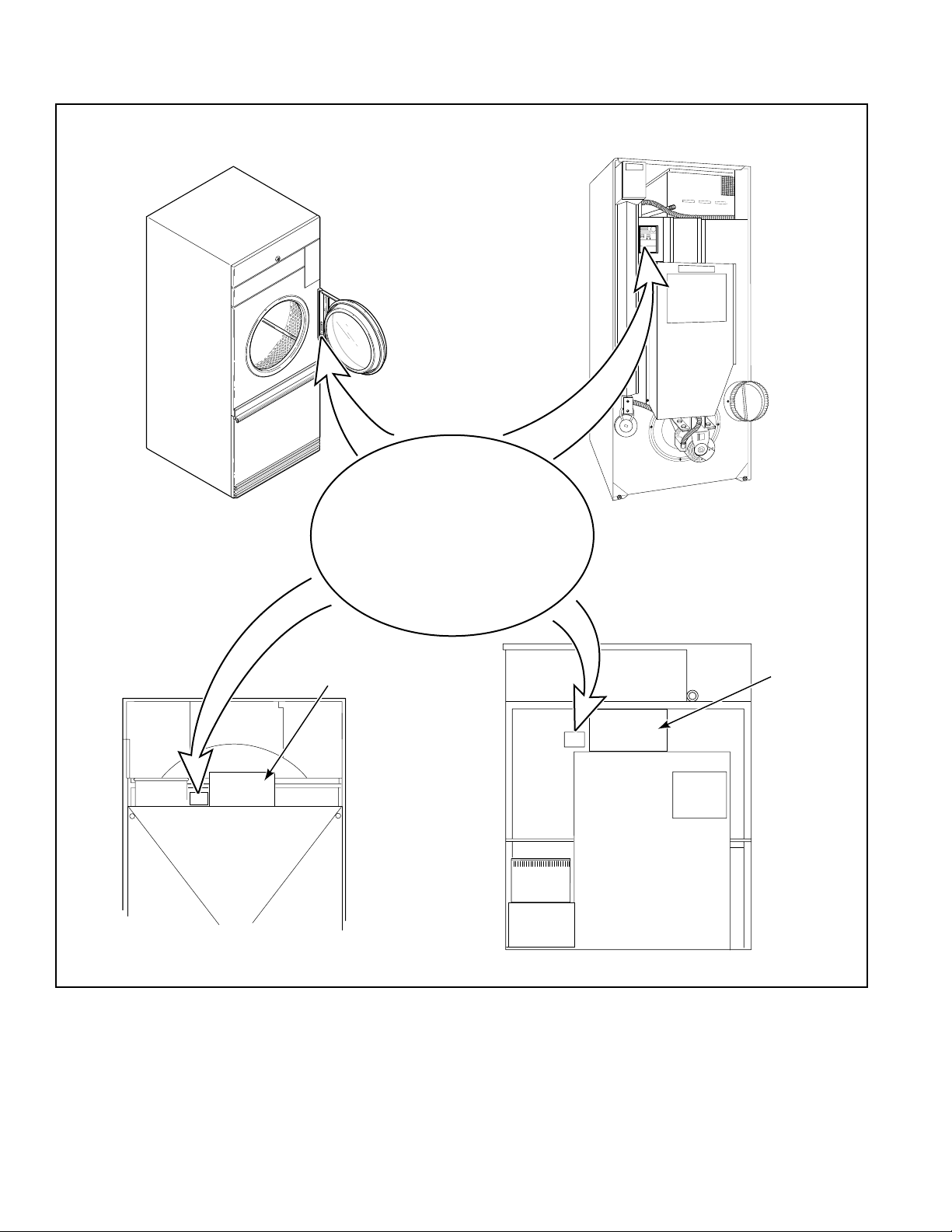
NAMEPLATE LOCATION
FOR THE 30, 50
AND 75 POUND
TUMBLER
FOR THE
120 POUND
TUMBLER
T276IE3B
INFORMATION
When writing for information
on any tumbler, be sure to
mention model and serial
numbers. The model and serial
numbers will be found on
the nameplate as shown.
JUNCTION BOX
COVER
T228IE3D
FOR THE
170 POUND
TUMBLER
T238IE3B
JUNCTION
BOX
COVER
T281IE3B
Figure 1
PARTS ORDERING INFORMATION
If literature or replacement parts are required, contact the source from whom the machine was purchased or contact
Alliance Laundry Systems at (920) 748-3950 for the name and address of the nearest authorized parts distributor. For
technical assistance, call (920) 748-3121.
8
M413620
Page 11
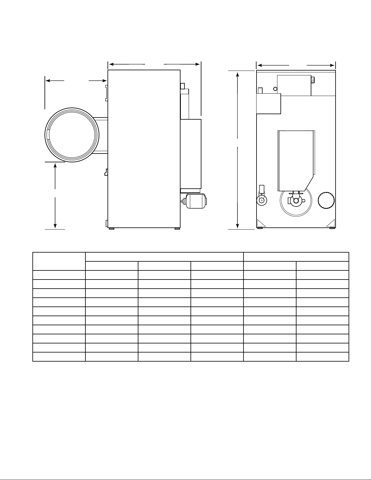
Roughing-In Dimensions and Specifications
Cabinet Dimensions
OPENING
CLEARANCE
DEPTH
WIDTH
HEIGHT
T326IE3A
TUMBLER MODELS
30XG/30WE 72-1/4" (1835 mm) 28" (711 mm) 44-7/8" (1140 mm) 26-3/4" (679 mm) 30-3/4" (781 mm)
30CG/30EG 72-1/4" (1835 mm) 31-1/2" (800 mm) 46-11/16" (1186 mm) 28-1/4" (717 mm) 30-3/4" (781 mm)
30CE/30CSH 72-1/4" (1835 mm) 31-1/2" (800 mm) 44-7/8" (1140 mm) 28-1/4" (717 mm) 30-3/4" (781 mm)
30CSL 72-1/4" (1835 mm) 31-1/2" (800 mm) 45-1/32" (1144 mm) 28-1/4" (717 mm) 30-3/4" (781 mm)
50CG/50EG/50CE 76-5/8" (1946 mm) 38-5/8" (981 mm) 47" (1194 mm) 28-1/4" (717 mm) 30-3/4" (781 mm)
50CSL/50CSH 80" (2032 mm) 38-5/8" (981 mm) 47" (1194 mm) 28-1/4" (717 mm) 30-3/4" (781 mm)
75CG/75EG/75CE/634 76-5/8" (1946 mm) 38-5/8" (981mm) 53" (1346 mm) 28-1/4" (717 mm) 30-3/4" (781 mm)
75CSL/75CSH 80" (2032 mm) 38-5/8" (981 mm) 53" (1346 mm) 28-1/4" (717 mm) 30-3/4" (781 mm)
120FG*/120CSH* 85-1/2" (2172 mm) 46-1/2" (1181 mm) 65" (1235 mm) 30-1/2" (775 mm) 31-5/16" (795 mm)
170FG*/170CSH* 94" (2390 mm) 53-1/8" (1349 mm) 66-1/8" (1679 mm) 30-1/2" (775 mm) 33-5/16" (857 mm)
HEIGHT WIDTH DEPTH OPENING CLEARANCE
OVERALL DOOR
* See Section III “Positioning the Drying Tumbler” for temporarily reducing the height of these models.
M413620
9
Page 12
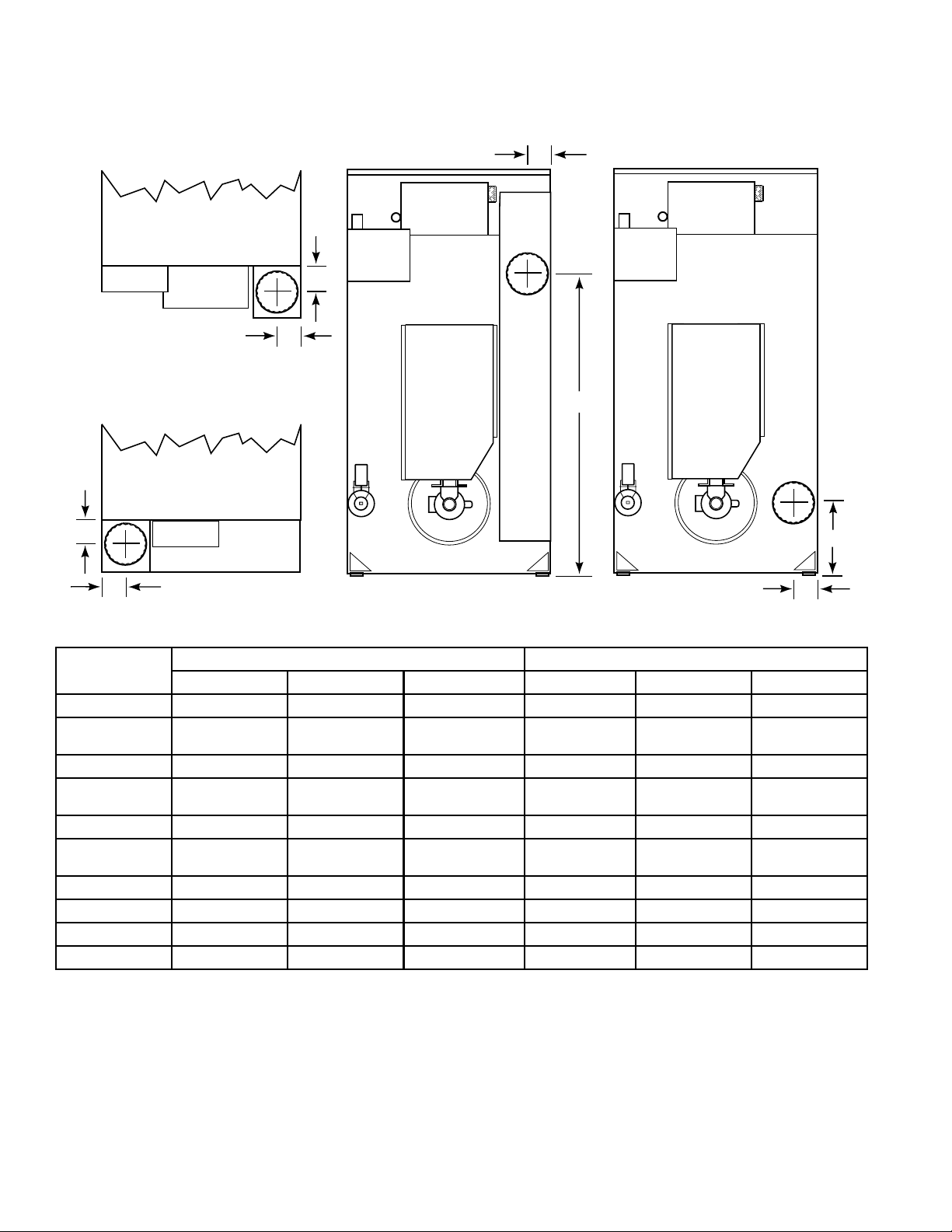
Roughing-In Dimensions and Specifications
Exhaust Thimble Locations
DEPTH
30XG, 30WE & 75EG
ACROSS
120FG, 120CSH,
170FG & 170CSH
ACROSS
ACROSS
DEPTH
HEIGHT
HEIGHT
ACROSS
T327E3A
TUMBLER MODELS
30XG/30WE N/A N/A N/A 6" (152 mm) 3-3/8" (86 mm) 3-3/8" (86 mm)
30CG/30CE
30CSL/30CSH
30EG 8" (203 mm) 4-7/16" (113 mm) 55-3/8" (1407 mm) N/A N/A N/A
50CG/50CE
50CSL/50CSH
50EG 8" (203 mm) 5-3/8" (137 mm) 57-5/8" (1464 mm) N/A N/A N/A
75CG/75CE
75CSL/75CSH
75EG N/A N/A N/A 8" (203 mm) 5-5/8" (143 mm) 5" (127 mm)
634 10" (254 mm) 6-1/2" (165 mm) 6-1/2" (165 mm) N/A N/A N/A
120FG/120CSH N/A N/A N/A 10" (254 mm) 203 mm (8") 7-1/2" (185 mm)
170FG/170CSH N/A N/A N/A 12" (305 mm) 7" (178 mm) 9-3/8" (238 mm)
DIAMETER ACROSS HEIGHT DIAMETER ACROSS HEIGHT
8" (203 mm) 4-7/16" (113 mm) 21-7/8" (556 mm) N/A N/A N/A
8" (203 mm) 5-3/8" (137 mm) 13-3/8" (340 mm) N/A N/A N/A
8" (203 mm) 5-3/8" (137 mm) 13-3/8" (340 mm) N/A N/A N/A
HORIZONTAL EXHAUST VERTICAL EXHAUST
10
M413620
Page 13
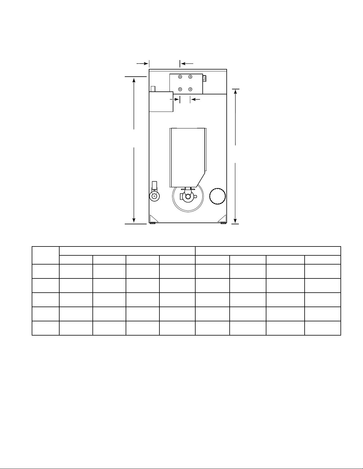
Roughing-In Dimensions and Specifications
Steam Connection Locations
ACROSS
SPAN
STEAM
INLET
HEIGHT
STEAM
OUTLET
HEIGHT
TUMBLER
MODELS
30CSL
30CSH
50CSL
50CSH
75CSL
75CSH
120CSH 3/4" (19 mm)
170CSH 3/4" (19 mm)
DIAMETER ACROSS HEIGHT SPAN DIAMETER ACROSS HEIGHT SPAN
3/4" (19 mm)
I.D.
3/4" (19 mm)
I.D.
3/4" (19 mm)
I.D.
I.D.
I.D.
STEAM INLET STEAM OUTLET
14" (356 mm) 68-3/4"
15-1/4"
(387 mm)
15-1/4"
(387 mm)
21-1/4"
(540 mm)
15-3/4"
(400 mm)
(1746 mm)
72-3/4"
(1848 mm)
72-3/4"
(1848 mm)
82-3/4"
(2102 mm)
88"
(2235 mm)
7-1/2"
(190 mm)
7-1/2"
(190 mm)
7-1/2"
(190 mm)
N/A (Manifold) 1" (25 mm)
21-5/8"
(549 mm)
3/4" (19 mm)
I.D.
3/4" (19 mm)
I.D.
3/4" (19 mm)
I.D.
N.P.T.
1" (25 mm)
N.P.T.
T328E3A
14" (356 mm) 61-1/4"
15-1/4"
(387 mm)
15-1/4"
(387 mm)
11-7/8"
(302 mm)
8-3/4"
(222 mm)
(1556 mm)
64-3/4"
(1645 mm)
64-3/4"
(1645 mm)
68-1/2"
(1739 mm)
71-3/4"
(1822 mm)
7-1/2"
(190 mm)
7-1/2"
(190 mm)
7-1/2"
(190 mm)
21-1/2"
(546 mm)
35-5/8"
(905 mm)
M413620
11
Page 14

Roughing-In Dimensions and Specifications
Gas Connection Locations
ACROSS
HEIGHT
T329E3A
TUMBLER
MODELS
30XG 1/2" (12.7 mm) 12-1/4" (311 mm) 62-1/8" (1578 mm)
30CG/30EG 1/2" (12.7 mm) 15" (381 mm) 62-1/8" (1578 mm)
50CG/50EG 1/2" (12.7 mm) 15-1/2" (394 mm) 65-3/4" (1670 mm)
75CG/75EG 1/2" (127 mm) 15-3/4" (400 mm) 65-3/4" (1670 mm)
634 3/4" (19 mm) 15-3/4" (400 mm) 65-3/4" (1670 mm)
120FG 3/4" (19 mm) 33-1/2" (851 mm) 70-1/4" (1784 mm)
170FG 1" (25 mm) 38-5/8" (979 mm) 77-3/8" (1965 mm)
DIAMETER (N.P.T.) ACROSS HEIGHT
GAS CONNECTION
12
M413620
Page 15
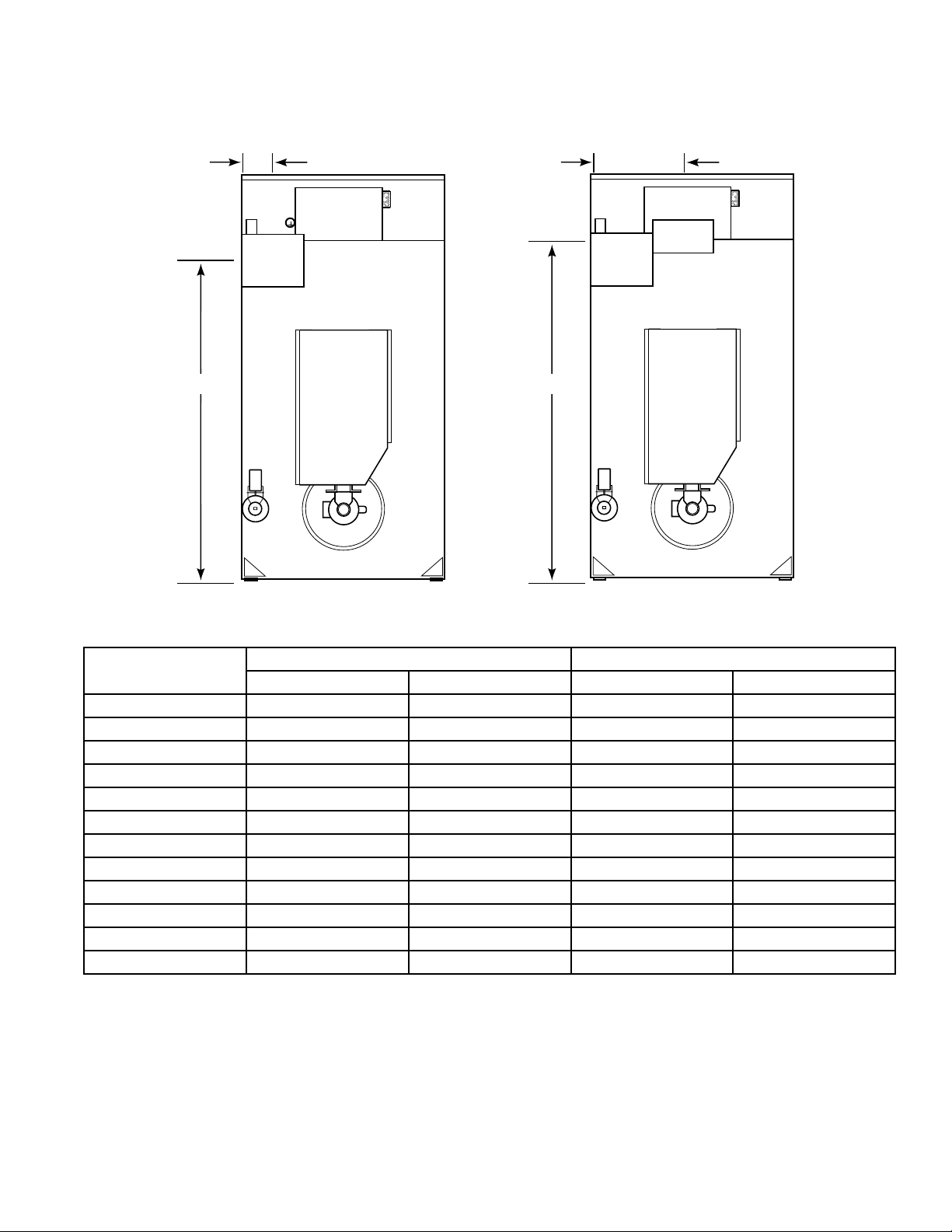
Roughing-In Dimensions and Specifications
Electrical Connection Locations
HEIGHT
ACROSS
Gas & Steam
HEIGHT
Electric
ACROSS
T330iE3A
TUMBLER
MODELS
30XG/30CG/30EG 65" (1651 mm) 3" (76 mm) N/A N/A
30WE N/A N/A 60" (1524 mm) 14" (356 mm)
30CE N/A N/A 60" (1524 mm) 16" (406 mm)
30CSL/30CSH 65" (1651 mm) 3" (76 mm) N/A N/A
50CG/50EG 68" (1727 mm) 3" (76 mm) N/A N/A
50CE N/A N/A 64" (1626 mm) 19" (483 mm)
50CSL/50CSH 68" (1727 mm) 3" (76 mm) N/A N/A
75CG/75EG 68" (1727 mm) 3" (76 mm) N/A N/A
75CE N/A N/A 64" (1626 mm) 19" (483 mm)
75CSL/75CSH/634 68" (1727 mm) 3" (76 mm) N/A N/A
120FG/120CSH 65" (1651 mm) 24" (610 mm) N/A N/A
170FG/170CSH 68" (1727 mm) 27" (686 mm) N/A N/A
ELECTRICAL SERVICE - GAS & STEAM MODELS ELECTRICAL SERVICE - ELECTRIC MODELS
HEIGHT ACROSS HEIGHT ACROSS
NOTE: These are approximate dimensions only.
M413620
13
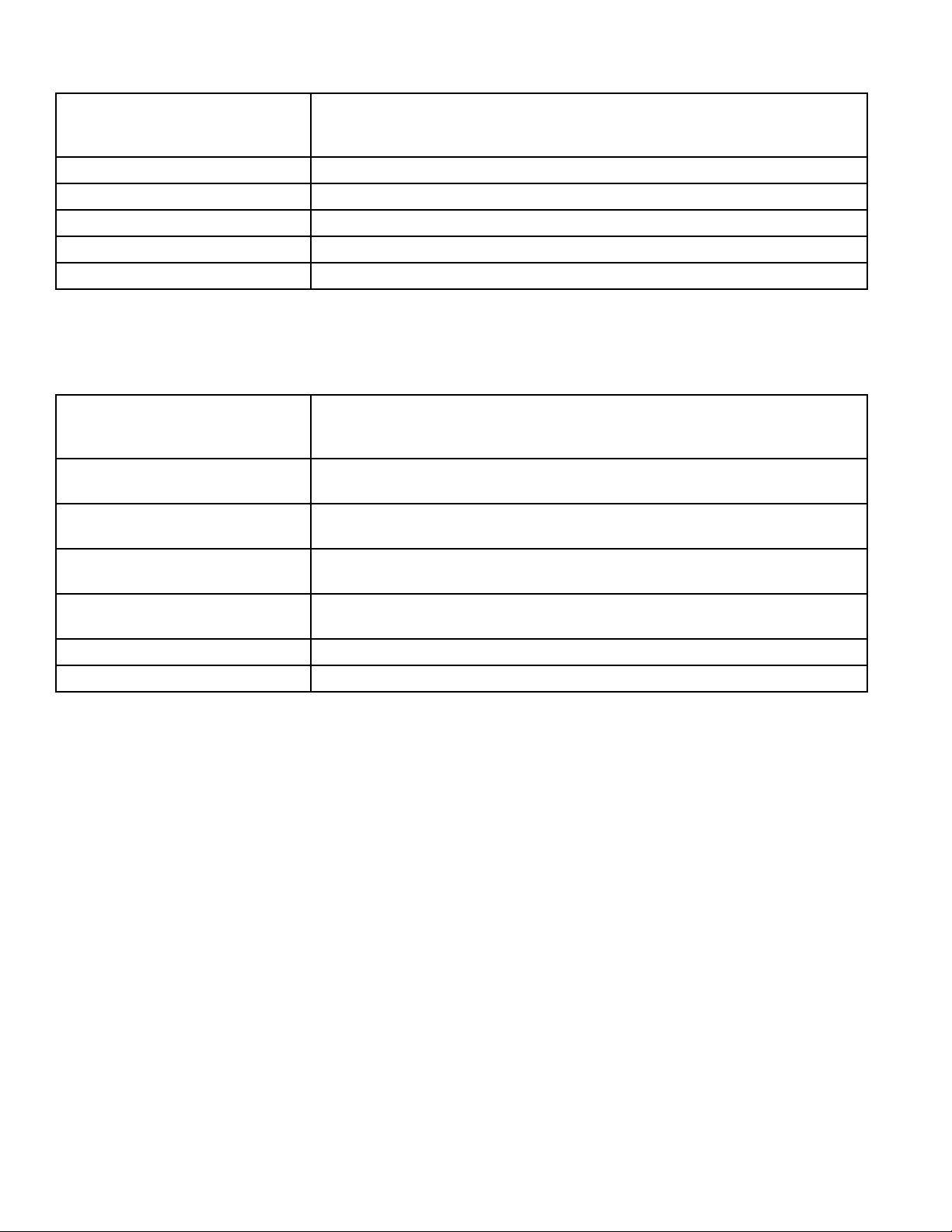
Page 16
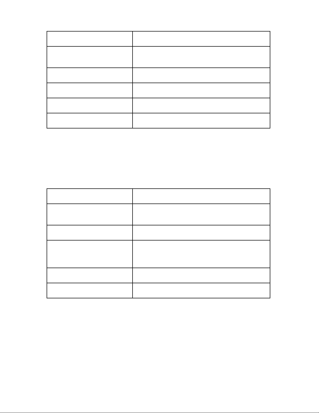
30 Pound, 28" wide Gas Tumbler
Cabinet Finish: Electrostatically applied thermosetting polyester.
Cylinder: 26.5" x 30" (67.3 cm x 76.2 cm)
perforated galvanized steel with three baffles
Motor: 1/3 H.P., lifetime lubricated, internal overload protected
Gas Consumption: 75,000 BTU per hour (79.1 MJ/hr.)
Max. Air Flow: 370 C.F.M. (175 liters/sec.)
Net Weight: 350 Pounds (159 kg) (approximate)
30 Pound, 28" wide Electric Tumbler
Cabinet Finish: Electrostatically applied thermosetting polyester.
Cylinder: 26.5" x 30" (67.3 cm x 76.2 cm)
perforated galvanized steel with three baffles
Motor: 1/3 H.P., lifetime lubricated, internal overload protected
Element: 21,000 Watts (60 Hz models)
Long life nichrome wire
18,000 Watts (50 Hz models)
Max. Air Flow: 625 C.F.M. (295 liters/sec.)
Net Weight: 410 Pounds (184.5 kg) (approximate)
14
M413620
Page 17

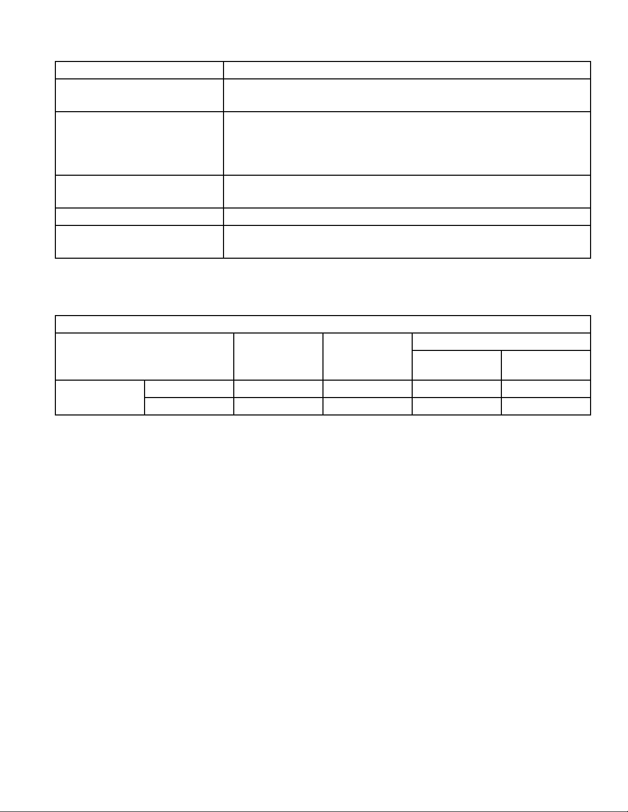
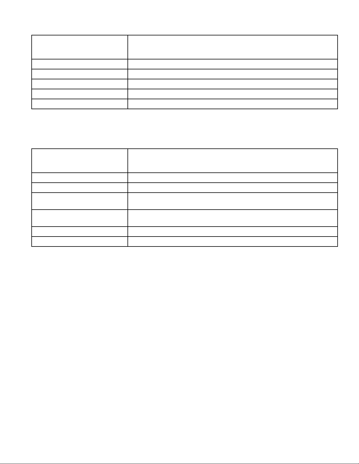
30 Pound Gas Tumbler
Cabinet Finish: Electrostatically applied thermosetting polyester.
Cylinder: 30" x 30" (76.2 cm x 76.2 cm) perforated galvanized steel with three baffles;
30 pounds (13.6 kg) dry weight (cotton load)
Motor: 1/3 H.P., lifetime lubricated, internal overload protected
Energy Saver Models — 80,000 BTU per hour (84.4 MJ/hr.)
Gas Consumption:
Standard Models — 105,000 BTU per hour (110.8 MJ/hr.)
Gas Connection: 1/2 inch N.P. T.
Max. Air Flow: Energy Saver Models — 250 C.F.M. (118 liters/sec.)
Standard Models — 625 C.F.M. (295 liters/sec.)
Net Weight: 450 Pounds (204 kg) (approximate)
30 Pound Electric Tumbler
Cabinet Finish: Electrostatically applied thermosetting polyester.
Cylinder: 30" x 30" (76.2 cm x 76.2 cm) perforated galvanized steel with three baffles;
30 pounds (13.6 kg) dry weight (cotton load)
Motor: 1/3 H.P., lifetime lubricated, internal overload protected
Element: 21,000 Watts (all voltages)
Max. Air Flow: 625 C.F.M. (295 liters/sec.)
Net Weight: 450 Pounds (204 kg) (approximate)
30 Pound Steam Tumbler
Cabinet Finish: Electrostatically applied thermosetting polyester.
Cylinder: 30" x 30" (76.2 x 76.2 cm) perforated galvanized steel with three baffles;
30 pounds dry weight (13.6 kg) (cotton load)
Motor: High Pressure (4 coils) 1/2 H.P.
Low Pressure (4 coils) 3/4 H.P.
Boiler Horsepower: 4 coil High Pressure – 3.7 Bhp (123,950 BTU/hr., 58 kg/hr, 31,235 kCal/hr.)
4 coil Low Pressure – 2.6 Bhp (87,100 BTU/hr., 40 kg/hr, 21,949 kCal/hr.)
Max. Air Flow: 625 C.F.M. (295 liters/sec.)
Net Weight: 470 Pounds (214 kg) (approximate)
M413620
15
Page 18

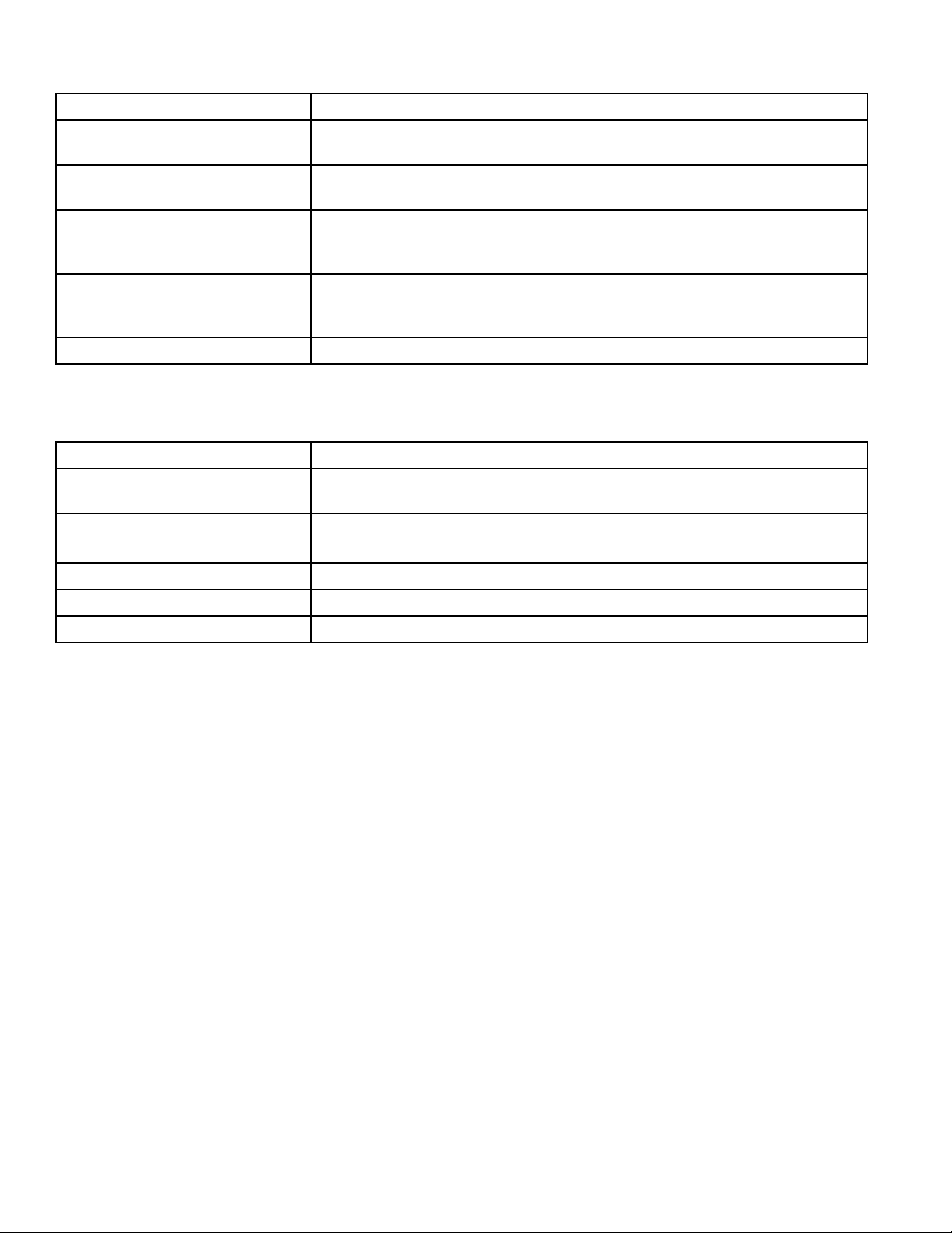
50 Pound Gas Tumbler
Cabinet Finish: Electrostatically applied thermosetting polyester.
Cylinder: 37" x 30" (94 cm x 76.2 cm) perforated galvanized steel with four baffles;
50 pounds (22.7 kg) dry weight (cotton load)
Motor:
(Nonreversing Models)
Gas Consumption:
Max. Air Flow: Energy Saver Models — 390 C.F.M. (184 liters/sec.)
Net Weight: 545 Pounds (247 kg) (approximate)
1/2 H.P., lifetime lubricated, internal overload protected
(See below for reversing models.)
Energy Saver Models — 95,000 BTU per hour (100.2 MJ/hr.)
Standard Models — 120,000 BTU per hour (126.6 MJ/hr.)
Standard Models — 750 C.F.M. (354 liters/sec.)
50 Pound Electric Tumbler
Cabinet Finish: Electrostatically applied thermosetting polyester.
Cylinder: 37" x 30" (94 cm x 76.2 cm) perforated galvanized steel with four baffles;
50 pounds (22.7 kg) dry weight (cotton load)
Motor:
(Nonreversing Models)
1/2 H.P., lifetime lubricated, internal overload protected
(See below for reversing models.)
Element: 21,000 watts (240 VAC 50 Hz.) Long life nichrome wire
30,000 watts (all other voltages) Long life nichrome wire
Max. Air Flow: 750 C.F.M. (354 liters/sec.)
Net Weight: 550 Pounds (250 kg) (approximate)
16
M413620
Page 19
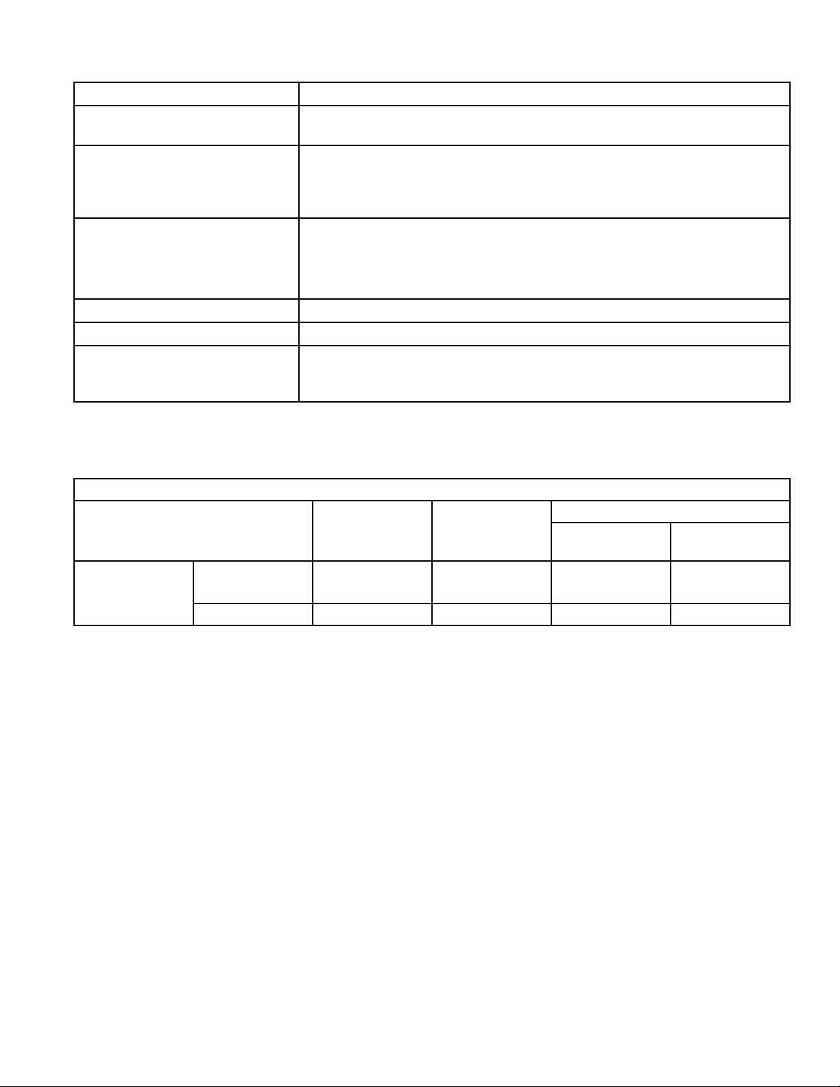
50 Pound Steam Tumbler
Cabinet Finish: Electrostatically applied thermosetting polyester.
Cylinder: 37" x 30" (94 x 76.2 cm) perforated galvanized steel with four baffles;
50 pounds (22.7 kg) dry weight (cotton load)
Motor:
(Nonreversing Models)
Boiler Horsepower: High Pressure Steam (6 Coil) — 4.60 B.H.P.
Max. Air Flow: 750 C.F.M. (354 liters/sec)
Net Weight: 4 Coil Tumbler — 565 pounds (257 kg) (approximate)
High Pressure Steam — 1/2 H.P.
Low Pressure Steam — 3/4 H.P
Both motors are lifetime lubricated, internal overload protected
See below for reversing models.
Low Pressure Steam (4 Coil) — 3.00 B.H.P.
6 Coil Tumbler — 580 pounds (263 kg) (approximate)
REVERSING MOT OR SIZES
STEAM
GAS ELECTRIC
HIGH
PRESSURE
LOW
PRESSURE
50 LB.
FAN 1/3 H.P. 1/3 H.P. 1/3 H.P. 1/2 H.P.
CYLINDER 1/3 H.P. 1/3 H.P. 1/3 H.P. 1/3 H.P.
M413620
17
Page 20
75 Pound Gas Tumbler
Cabinet Finish: Electrostatically applied thermosetting polyester.
Cylinder: 37" x 36" (94 x 91.4 cm) perforated galvanized steel cylinder with four baffles;
75 pounds (34.1 kg) dry weight (cotton load)
Motor: 3/4 H.P., lifetime lubricated, internal overload protected. See below for
reversing models.
Standard Models: 165,000 B.T.U. per hour (174.1 MJ/hr.)
Gas Consumption:
Max. Air Flow: Standard Models: 920 C.F.M. (434 liters/sec.)
Net Weight: 575 Pounds (261 kg) (approximate)
Energy Saver Models: 140,000 B.T.U. per hour (147.7 MJ/hr.)
DTB634 Models: 215,000 B.T.U. per hour (227 MJ/hr.)
Energy Saver Model: 500 C.F.M. (236 liters/sec.)
634 Models: 1100 C.F.M. (519 liters/sec.)
75 Pound, Electric, Non-reversing Tumbler
Cabinet Finish: Electrostatically applied thermosetting polyester.
Cylinder: 37" x 36" (94 x 91.4 cm) perforated galvanized steel with four baffles;
75 pounds (34.1 kg) dry weight (cotton load)
Motor: 3/4 H.P., lifetime lubricated, internal overload protected. See below for
reversing models.
Element: 30,0 00 watts (all models)
Max. Air Flow: (C.F.M.) 750 C.F.M. (354 liters/sec.)
Net Weight: 555 Pounds (252 kg) (approximate)
18
M413620
Page 21
75 Pound Steam Tumbler
Cabinet Finish: Electrostatically applied thermosetting polyester.
Cylinder: 37" x 36" (94 x 91.4 cm) perforated galvanized steel with four baffles;
75 pounds (34.1 kg) dry weight (cotton load)
Motor: High Pressure Steam — 3/4 H.P.
Low Pressure Steam — 3/4 H.P.
Both motors are lifetime lubricated, internal overload protected.
See below for reversing models.
Electrical Boiler Horsepower: High Pressure Steam — 4.60 BPH (154,100 BTU/hr.)
(72.1 kg/hr., 38,833 kCal/hr.)
Low Pressure Steam — 4.00 BHP (134,000 BTU/hr.)
(62.7 kg/hr., 33,768 kCal/hr.)
Max. Air Flow: 750 C.F.M. (354 liters/sec)
Net Weight: 6 Coil Tumbler — 615 pounds (280 kg) (approximate)
Electrical Requirements:
(Reversing Models)
75 LB.
* 634 Models
208-240 Volt, 60 Hertz, 3 Phase, 4 Amp.
480 Volt, 60 Hertz, 3 Phase, 2 Amp
240 Volt, 50 Hertz, 1 Phase, 8 Amp
REVERSING MOT OR SIZES
STEAM
GAS ELECTRIC
FAN
CYLINDER 1/3 H.P. 1/3 H.P. 1/3 H.P. 1/3 H.P.
1/3 H.P.
1 H.P.*
1/3 H.P. 1/3 H.P. 1/2 H.P.
HIGH
PRESSURE
LOW
PRESSURE
M413620
19
Page 22
120 Pound Gas Tumbler
Cylinder: 44" diameter x 41" deep (111.8 cm x 104.1 cm)
Perforated galvanized steel with four baffles;
120# dry weight (cotton load).
Cylinder Motor: 3/4 H.P., lifetime lubricated, internal overload protected.
Fan motor: 1 H.P. lifetime lubricated, internal overload protected.
Gas Consumption: 300,000 BTU/hr (316 MJ/hr)
Air Flow: 2000 CFM at .3" W.C. (944 liters/sec at .76 cm W.C.)
Net Weight (approx.): 1275 pounds (580 kg)
120 Pound Steam Tumbler
(Not Agency Listed)
Cylinder: 44" diameter x 41" deep (111.8 cm x 104.1 cm)
Perforated galvanized steel with four baffles;
120# dry weight (cotton load).
Cylinder Motor: 3/4 H.P. lifetime lubricated,
internal overload protected
Fan Motor: 1 H.P. lifetime lubricated,
internal overload protected
Steam Consumption (maximum): 10 B.H.P (156.8 kg/hr)
335,000 BTU/hr (84,419 kCal/hr)
Operating Steam Pressure
(maximum):
Air Flow: 2000 CFM at .3" W.C. (944 liters/sec at .76 cm W.C.)
Net Weight (approx.): 1375 pounds (625 kg)
125 psi (8.79 kg/sq cm)
20
M413620
Page 23
170 Pound Gas Tumbler
Cylinder: 50-3/4" diameter x 42-1/2" deep (128.9 cm x 108. 9 cm)
Perforated galvanized steel with four baffles;
170# dry weight (cotton load).
Cylinder Motor: 3/4 H.P. lifetime lubricated
Fan Motor: 3 H.P. lifetime lubricated
Gas Consumption: 395,000 BTU/hr (401 MJ/hr)
Air Flow: 2300 CFM at .3" W.C. (1083.3 liters/sec at .76 cm W.C.)
Net Weight (approx.): 1575 pounds (716 kg)
170 Pound Steam Tumbler
(Not Agency Listed)
Cylinder: 50-3/4" diameter x 42-1/2" deep (128.9 cm x 108. 9 cm)
Perforated galvanized steel with four baffles;
170# dry weight (cotton load).
Cylinder Motor: 3/4 H.P. lifetime lubricated
Fan Motor: 3 H.P. lifetime lubricated
Steam Consumption (maximum): 15 B.H.P (235.2 kg/hr)
502,500 BTU/hr (126,630 kcal/hr)
Operating Steam Pressure
(maximum):
125 psi (8.79 kg/sq cm)
Air Flow: 2300 CFM at .3" W.C. (1083.3 liters/sec at .76 cm W.C.)
Net Weight (approx.): 1675 pounds (761 kg)
M413620
21
Page 24

Notes
22
M413620
Page 25

SECTION III
Installation Instructions
RECEIVING INSPECTION
Upon delivery, visually inspect crate carton and parts for
any visible shipping damage. If the crate, carton or co ver
are damaged or signs of possible damage are evident,
have the carrier n ote the condition on the shipping p apers
before the shipping receipt is signed, or advise the carrier
of the condition as soon as it is discovered.
Remove the crate and protecti ve cover as soon as possible
and check the items listed on the packing list. Advise the
carrier of any damaged or missing articles as soon as
possible. A written claim should be filed with the carrier
immediately if articles are damaged or missing.
IMPORTANT: Remove the shipping tape from the
two back draft dampers located in the exhaust
thimble.
MATERIALS REQUIRED
(Obtain Locally)
GAS, ELECTRIC OR STEAM DRYING
TUMBLERS
• One fused disconnect switch or circuit breaker.
GAS DRYING TUMBLERS ONLY
• One gas shut-off valve for gas service line to each
tumbler.
STEAM DRYING TUMBLERS ONLY
• One steam shut-off valve for steam service line to be
connected upstream of solenoid steam valve.
• Two steam shut-off valves for each condensate return
line.
• Flexible steam hoses with a 125 psig (pounds per
square inch gauge) (8.79 kg/sq. cm) working pressure
for connecting steam coils. See Figure 25, 26 and 27
for sizing and connection configurations.
• Two steam traps for steam coil outlet to condensate
return line. (Three for 120 and 170 pound tumblers. )
• Two vacuum breakers for condensate return lines.
(Three for 120 and 170 pound tumblers.)
M413620
23
Page 26

POSITIONING THE DRYING
LEVELING THE DRYING
TUMBLER
The tumbler may be removed from the skid before
moving it to the installation location or it may be moved
while still attached to the skid. To remove tumbler from
the skid, unscrew the four shipping capscrews (one at
each corner) and remove the tumbler from the skid. The
lint panel door will have to be removed in order to remove
the two front capscrews.
NOTE: Do not throw these four capscrews away —
they are the leveling legs.
Screw the four lev eling le gs back into the le v el adjusting
fittings from the top.
To fit a 170 pound tumbler (with shipping skid) through
an 8-foot high door, you must remove the front access
panel. The upper 3 inches of the stove must also be
removed on 170 pound gas tumblers. Removing the
entire gas or steam heater assembly and the shipping skid,
will reduce the height of the 120 pound tumbler to 70
inches, and the 170 pound tumbler to 75 inches.
To remove tumbler from the skid, unscrew the four
shipping capscrews (one at each corner) and remove the
tumbler from the skid.
Slide the tumbler to its permanent location and level.
Keep the tumbler as close to the floor as possible. The
tumbler must rest firmly on the floor so weight of tumbler
is evenly distrib uted. T umbler must not rock. Shim under
the corners to level and stabilize the unit.
TUMBLER
Each tumbler should be leveled within 1/8 inch (3.2 cm)
from front to rear, and 1/8 inch (3.2 cm) from side to side.
Check front to rear level by rotating the clothes cylinder
until one rib is at the bottom, then place a level on the rib .
Side to side level should be checked by placing a le vel on
the front and rear of the top panel.
24
M413620
Page 27
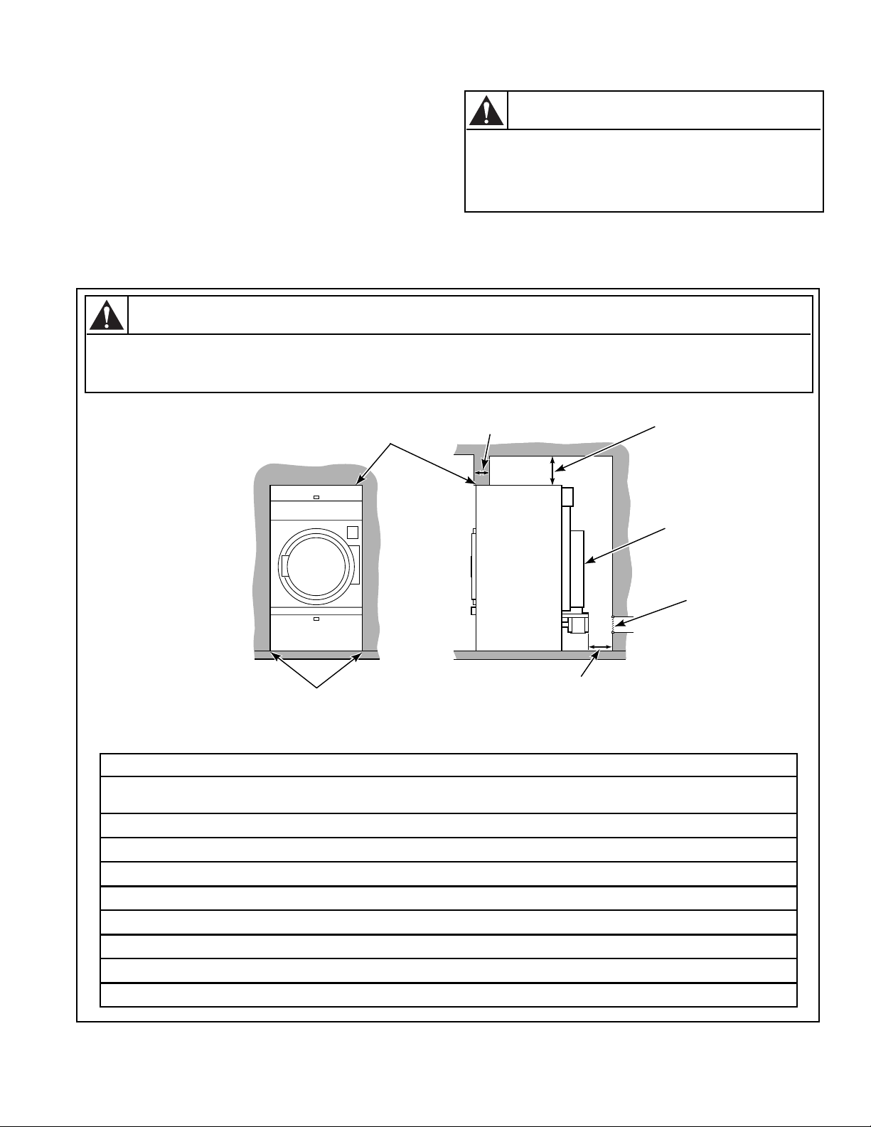
DRYING TUMBLER ENCLOSURE CONSTRUCTION
IMPORTANT: DO NOT block the air flow at the rear
of the tumbler with laundry or other articles. Doing
so would prevent adequate air supply to the
combustion chamber of the tumbler.
A typical tumbler enclosure is shown in Figure 2. Note
that the enclosure touches the tumbler top and side
T o reduce the risk of serious injury, install
lockable door(s) to prevent public access
to rear of tumblers.
panels. Also, note the minimum and maximum
dimensions. Be aware that there may be local codes and
ordinances which must be complied with.
IMPORTANT: Install tumblers with sufficient
clearance for servicing and operation, see Figure 2.
WARNING
To reduce the risk of severe injury, clearance of tumbler cabinet from combustible
construction must conform to the minimum clearances.
WARNING
W055
W056
12" (30.5 cm)
MINIMUM
CLEARANCE
PERMITTED
FOR REMAINDER
GUARD
PROVISION
MAKE-UP
T038IE3D
NOTE: Shaded areas
indicate adjacent
structure.
0" CLEARANCE PERMITTED
FOR FIRST 4" (10.16 cm)
0" CLEARANCE
4" (10.16 cm)
MAXIMUM
24" (61 cm) MINIMUM
36" (91.4 cm) RECOMMENDED
FOR MAINTENANCE PURPOSES
Minimum Recommended Clearances
Model Top
First 4" (10.2 cm)
Top
(Remainder)
Back Sides
All 30# (28") 0" (0.0 cm) 12" (30.5 cm) 24" (61 cm) 0" (0 cm)
FOR
AIR
All 30# (31.5") 0" (0.0 cm) 12" (30.5 cm) 24" (61 cm) 0" (0 cm)
All 50# 0" (0.0 cm) 12" (30.5 cm) 24" (61 cm) 0" (0 cm)
All 75# 0" (0.0 cm) 12" (30.5 cm) 24" (61 cm) 0" (0 cm)
Gas 120# 0" (0.0 cm) 4" (10.2 cm) 24" (61 cm) 0" (0 cm)
Steam 120# 0" (0.0 cm) 18" (45.7 cm) 24" (61 cm) 0" (0 cm)
Gas 170# 0" (0.0 cm) 4" (10.2 cm) 24" (61 cm) 0" (0 cm)
Steam 170# 0" (0.0 cm) 18" (45.7 cm) 24" (61 cm) 0" (0 cm)
Figure 2
M413620
25
Page 28
FACILITIES REQUIRED
To assure compliance, consult local building code
requirements.
WARNING
A drying tumbler produces combustible
lint. To reduce the risk of fire, the tumbler
must be exhausted to the outdoors.
W057
FLOOR
The drying tumbler must be installed on a level floor
capable of supporting 100 pounds per square fo ot (488.3
kg/sq. m) for 30, 50 and 75 pound tumblers. The floor
must be capable of supporting 120 pound s per square foot
(585.8 kg/sq. m) for 120 and 1 70 poun d tumblers. Floor
covering materials such as carpeting or tile should be
removed.
• Individual Venting
For maximum efficiency and performance, it is
preferred to exhaust tumbler(s) individually to the
outdoors. At no point may the cross area of installed
venting be less than the cross area of the exhaust
thimble of the tumbler.
The maximum allowable length venting is 14 feet (4.3
m) and two 90° elbo ws o r equivalent. If the equivalent
length of a duct required for an installation exceeds the
maximum allowable equiv alent length, the diameter of
a round duct must be increased by 10% for each
additional 20 feet (6.1 m). Cross section area of a
rectangular duct must be increased by 20% for each
addtional 20 feet (6.1 m). Table below shows how to
determine equiv a lent venting:
DUCT
DIAMETER
EQUIVALENT LENGTH OF
STRAIGHT DUCT
LAYOUT
Whenever possible, tumblers should be installed along an
outside wall where duct length can be kept to a minimum,
and make-up air can be easily accessed. Construction
must not block the airflow at the top rear of the tumbler.
Doing so would prevent adequate air supply to the
tumbler’s combustion chamber.
VENTING
For maximum efficiency and minimum lint
accumulation, tumbler air must be exhausted to the
outdoors by the shortest possible route.
Proper sized exhaust ducts are essential for proper
operation. All elbows should be sweep type. Exhaust
ducts must be assembled so the interior surfaces are
smooth, so the joints do not permit the accumulation of
lint. Do not use sheet metal screws to join vent sections.
Improperly sized or assembled ductwork causes excess
back pressure which results in slow drying, lint collecting
in the duct, lint blowing back into the room, and
increased fire hazard.
Exhaust ducts shall be constructed of sheet metal or
other noncombustible material. Such ducts must be
equivalent in strength and corrosion resistance to
ducts made of galvanized sheet steel not less than
0.0195 inches (0.495 mm) thick.
6" (15.2 cm)
8" (20.3 cm)
10" (25.40 cm)
12" (30.48 cm)
14" (35.56 cm)
16" (40.64 cm)
18" (45.72 cm)
Equivalent Length (feet) = 1.7 x Duct Diameter
(inches)
Example: A 12" diameter duct’s equivalent
length of 14 feet of duct and two 90° elbows is:
Equivalent Length = 14 feet + (2) 90° elbows
With the tumbler in operation, airflow at any point in
the duct must be at least 1200 feet per minute (366 m./
min.) to insure that the lint remains airborne.
One 90° elbow = 7 feet (2.1 m)
One 90° elbow = 9.3 feet (2.83 m)
One 90° elbow = 11.6 feet (3.5 m)
One 90° elbow = 14 feet (4.3 m)
One 90° elbow = 16 feet (4.9 m)
One 90° elbow = 18.7 feet (5.7 m)
One 90° elbow = 21 feet (6.4 m)
Table 1
= 14 feet + 14 feet + 14 feet
= 42 feet (12.8 m)
Where the exhaust duct pierces a combustible wall or
ceiling, an opening having a diameter of 4 inches (10.2
cm) larger than the diameter of the exhaust duct shall be
provided, with the duct centered in the opening. When
ducts pass through walls, ceilings, floors or partitions, the
space around the duct shall be sealed with noncombustible material. See Figures 3, 4 and 5.
26
M413620
Page 29
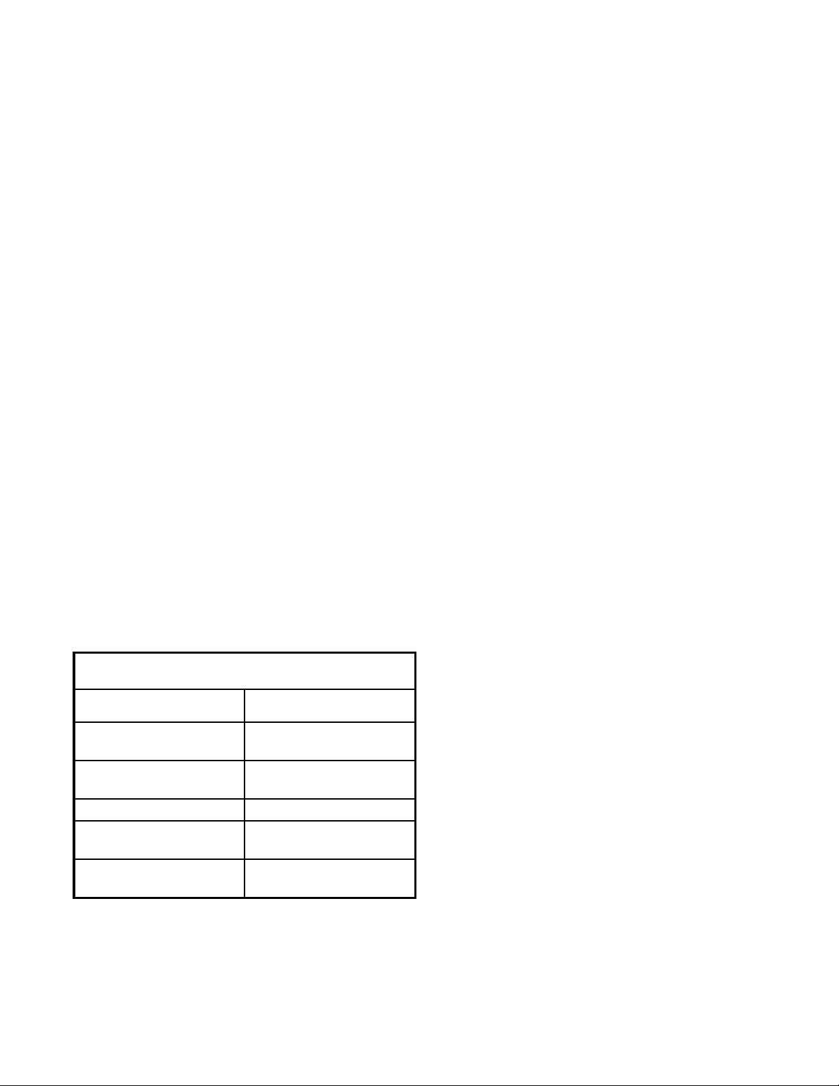
• Collector Venting
While it is preferable to exhaust tumblers individually
to the outdoors, a main collector duct may be used if it
is sized according to Figure 5. This illustration
indicates minimum diameters, and should be increased
if the collector length exceeds 20 feet (6.1 m). The
collector duct may be rectangular in cross section, as
long as the area is not reduced. Provisions should be
made for lint removal and cleaning of the collector
duct.
The collector duct must be tapered, as shown in Figur e
5. The individual tumbler ducts must enter the
collector duct at a 45° angle in the direction of air flow .
Never connect a tumbler duct at a 90° angle to the
collector duct. Doing so will cause excessive back
pressure, resulting in poor perf ormance. Never
connect two tumbler exhaust ducts directly across
from each other at the point of entry to the collector
duct.
The collector system must be designed so the static
back pressure measured 12 inches (30.5 cm) from the
exhaust thimble does not exceed the maximum
allowable pressure specified on the installation sticker
on the rear of the tumbler. This must be measured with
all tumblers running that are vented into the collector.
At a minimum, the National Fuel Gas Code requires
tumblers to have at least one square inch (6.5 sq. cm)
of opening for every 1000 BTU/hr. of input rating for
proper combustion.
Example: A tumbler with a rated input of 120,000
BTU/hr. requires 120 square inches of free
opening.
The additional opening recomended by the
manufacturer is required for optimum drying and
reliability.
Protective louvers in the opening to the outdoors can
reduce air movement by approximately 40 percent. The
opening must compensate for the area taken up by the
louvers.
The make-up air openings for a room containing
tumbler(s) and/or gas fired hot water heater or other
gravity vented appliances must be increased sufficiently
to prevent downdrafts in any of the vents when all
tumblers are in operation. Do not locate gravity vented
appliances between tumbler(s) and make-up air
openings. If it is necessary to duct make-up air to the
tumbler(s), increase the area of the duct work by 25
percent to compensate for any restriction in air
movement.
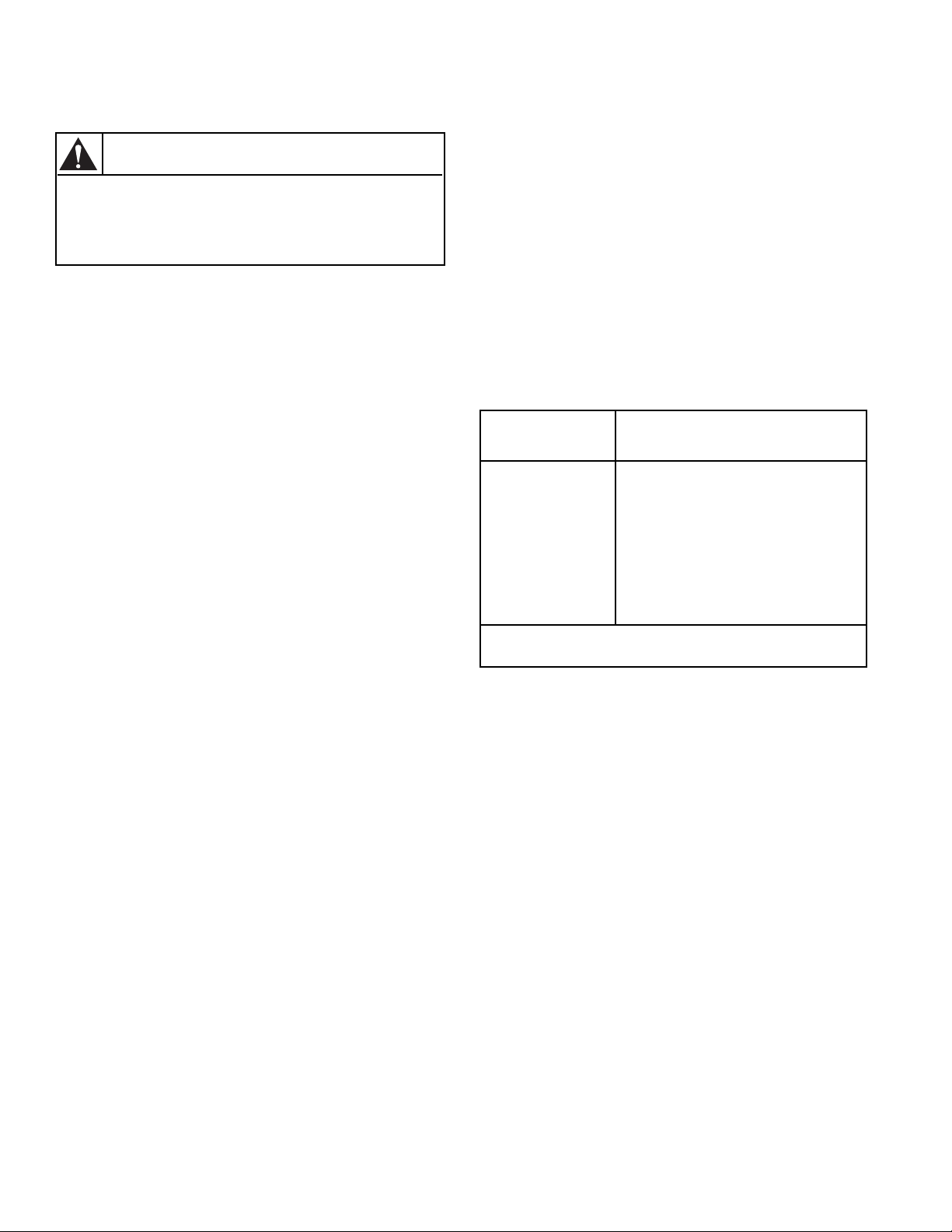
MAKE-UP AIR
A tumbler is forced air exhausted and requires provisions
for make-up air to replace the air exhausted by the
tumbler.
IMPORTANT: Do not obstruct the flow of
combustion and ventilation air.
Recommended Make-Up Air Opening
(to the outside) for Each Tumbler
Model
30#
50#
75EG
75EG
634 250 (1613)
120#
170#
Opening
2
(cm2)
Inches
144 (928)
195 (1258)
300 (1936)
free air
395 (2548)
free air
M413620
27
Page 30
WARNING
WARNING
Solvent gases and vapors from dry
cleaning machines create acids when
drawn through the heater of a drying
tumbler. These acids are corrosive to the
drying tumbler as well as to the laundry
load being dried. Be sure make-up air is
free of solvent gases and vapors.
If the dry cleaning machines are in the
same area as the tumbler, then the
tumbler make-up air must come from a
source free of solvent gases and vapors.
W058
FOR BEST PERFORMANCE
provide an individual exhaust
duct for each drying tumbler.
Do not install a hot water heater
in room containing drying
tumblers. It is better to have
the water heater in a separate
room with a separate air inlet.
To reduce the risk of fire and
accumulation of combustible gases, DO
NOT exhaust tumbler air into a window
well, gas vent, chimney or enclosed,
unventilated area such as an attic wall,
ceiling, crawl space under a building, or
concealed space of a building.
W059
NOTE: Do not install wire
mesh or screen in this
opening as lint will build up
and prevent proper discharge
of air from drying tumblers.
ROOF 30" (76.2 cm)
T108IE3A
T075IE3A
REMOVABLE STRIP OF PANEL IN FRAMING WALL
TO PERMIT REMOVAL OF DRYING TUMBLER
FROM FRAMING WALL
ONE
DRYING
TUMBLER
TWO
DRYING
TUMBLERS
TUMBLERS
THREE
DRYING
ROOF 30" (76.2 cm)
PARTITION OR
BULKHEAD
CONSULT YOUR LOCAL BUILDING
CODE FOR REGULATIONS WHICH
MAY ALSO APPLY
NOTE: Inside of duct shall be
smooth. Do not use sheet
metal screws to join sections.
CEILING
WALL
36 INCHES
(91.4 cm)
RECOMMENDED
SERVICE AREA
24 INCHES
(61.0 cm)
MINIMUM
T108IE3B
28
Figure 3
M413620
Page 31

VERTICAL EXHAUST INSTALLATION
HORIZONTAL EXHAUST INSTALLATION
WALL
CONNECT TO
TUMBLER
2" (5.1 cm)
MINIMUM
WALL
2" (5.1 cm)
MINIMUM
WALL
CONNECT TO
TUMBLER
EXHAUST AIR FLOW
MAXIMUM LENGTH OF
DUCT 14 FEET
(4.3 m)
NOTE: WHERE THE EXHAUST DUCT PIERCES A COMBUSTIBLE WALL
OR CEILING, AN OPENING HAVING A DIAMETER FOUR INCHES (10.2 cm)
LARGER THAN THE DIAMETER OF THE EXHAUST DUCT SHALL BE
PROVIDED, AND THE EXHAUST DUCT CENTERED WITHIN THE OPENING.
Figure 4
NOTE: WHERE THE EXHAUST DUCT PIERCES A COMBUSTIBLE WALL
OR CEILING, AN OPENING HAVING A DIAMETER FOUR INCHES (10.2 cm)
LARGER THAN THE DIAMETER OF THE EXHAUST DUCT SHALL BE
PROVIDED, AND THE EXHAUST DUCT CENTERED WITHIN THE OPENING.
T030IE3B
2" (5.1 cm)
MINIMUM
EXHAUST
OUTLET
NO SCREEN
OR CAP
INSPECTION OR
CLEANOUT COVER
ALKJ I HGFEDCB
NO SCREEN
OR CAP
DUCT
STATION
A
B
C
D
E
F
G
H
I
J
K
L
45˚
AIR OUT
MINIMUM DIAMETER
30 LB. 28" WIDE
GAS & ELEC.
30, 50, 75 LB.
GAS & ELEC.
30, 50, 75 LB.
STEAM, DTB634
120 LB.
GAS & STEAM
170 LB.
GAS & STEAM
7" (17.8 cm) 10" (25.4 cm) 10" (25.4 cm) 10" (25.4 cm) 12" (30.5 cm)
10" (25.4 cm) 12" (30.5 cm) 14" (35.6 cm) 15" (38.1 cm) 17" (43.2 cm)
12" (30.5 cm) 15" (38.1 cm) 17" (43.2 cm) 18" (45.7 cm) 21" (53.3 cm
14" (35.6 cm) 17" (43.2 cm) 20" (50.8 cm) 21" (53.3 cm) 24" (60.1 cm)
16" (40.6 cm) 19" (48.3 cm) 22" (55.9 cm) 24" (61.0 cm) 27" (68.6 cm)
18" (45.7 cm) 21" (53.3 cm) 24" (61.0 cm) 26" (66.0 cm) 30" (76.2 cm)
19" (48.3 cm) 23" (58.4 cm) 26" (66.0 cm) 28" (71.1 cm) 32" (81.3 cm)
20" (50.8 cm) 25" (63.5 cm) 28" (71.1 cm) 30" (76.2 cm) 34" (86.4 cm)
22" (55.9 cm) 26" (66.0 cm) 30" (76.2 cm) 32" (81.3 cm) 36" (91.4 cm)
23" (58.4 cm) 27" (68.6 cm) 31" (78.0 cm) 33" (83.8 cm) 38" (96.5 cm)
24" (61.0 cm) 29" (73.9 cm) 33" (83.8 cm) 35" (88.9 cm) 40" (101.6 cm)
25" (63.5 cm) 30" (76.2 cm) 34" (86.4 cm) 36" (91.4 cm) 42" (106.7 cm)
Figure 5
T056IE3B
M413620
29
Page 32

GAS REQUIREMENTS
WARNING
To reduce the risk of fire or explosion, DO
NOT CONNECT THE GAS LINE TO THE
TUMBLER IF THE GAS SERVICE IS NOT
THE SAME AS THAT SPECIFIED ON THE
TUMBLER SERIAL PLATE! It will first be
necessary to convert the gas burner
orifice and gas valve. Appropriate
conversion kits are available.
W060
IMPORTANT: Any product re visions or conversions
must be made by the Manufacturer’s Authorized
Dealers, Distributors or local service personnel.
WARNING
The tumbler and its individual shut-off
valve must be disconnected from the gas
supply piping system during an y pressure
testing of that system at test pressures in
excess of 1/2 psig (3.45 kPa).
The size of gas service pipe is dependent upon many
variables (lengths, tees, etc.). Specific pipe size
information should be obtained from the ga s supplier.
Refer to Tables 2 and 3 for general pipe size.
A dirt and water vapor pipe trap must be furnished and
installed by customer, see Figure 6.
It is important that equal pressure be maintained at all
tumbler gas connections. This can best be done by
installing a one inch (2.54 cm) pipe gas loop as shown in
Figures 7, 9 and 11.
WARNING
To reduce the risk of fire or explosion, if
the tumbler is to be connected to
Liquefied Petroleum (L.P.) gas, a vent to
the outdoors must be provided in the
room where the tumbler is installed.
W062
The tumbler must be isolat ed fr om the gas
supply piping system by closing its
individual manual shut-off valve during
any pressure testing of the gas supply
piping system at test pressure equal to or
less than 1/2 psig (3.45 kPa).
IMPORTANT: The installation must comply with
local codes or, in the absence of local codes:
• with the latest edition of the “National Fuel
Gas Code”, ANSI Z223.1 in the U.S.A.
• with CAN1-B149.1 or CAN1-B149.2 in
Canada
• and Australian Gas Association/Australian
L.P. Gas Association requirements in Australia
W061
30
M413620
Page 33

FOR 30, 50 AND 75 POUND
TUMBLERS
WARNING
NATURAL GAS service must be supplied at 6-1/2 ±
1-1/2 inch water column pressure (1.62 ± .37 kPa).
L.P. GAS service must be supplied at 11 ± .3 inch water
column pressure (2.74 ± .07 kPa).
FOR 120 AND 170 POUND
TUMBLERS
NATURAL GAS service must be supplied at 7 ± 1 inch
water column pressure (1.74 ± .23 kPa).
L.P. GAS service must be supplied at 11 ± .3 inch water
column pressure (2.74 ± .07 kPa).
Pressure checks can be made at the shut-off valve, see
Figure 6.
Purge air and sediment from the gas service line before
connecting it loosely to the tumbler. Purge remaining air
until odor of gas is detected, then tighten connection. Use
pipe compound, resistant to actions of L.P. gas, on all
pipe threads.
Check all pipe connections, internal and
external, for gas leaks using a soapy
solution. To reduce the risk of explosion
or fire, DO NOT USE AN OPEN FLAME TO
CHECK FOR GAS LEAKS! Gas
connections should be checked annually
for leakage.
W063
GAS LINE
TO
DRYER
CONTROLS
SHUT-OFF
VALVE
1/8" (.32 cm) N.P.T. plugged
tapping accessible for
pressure testing. Gauge
connection located upstream
from dryer main manual
shut-off
GAS SUPPLY
PIPING SYSTEM
GAS
“T” FITTING
6 INCHES (15.2 cm)
MINIMUM GAS PIPE
DIRT AND
WATER VAPOR
TRAP
GAS
PIPE CAP
T135IE1A
Figure 6
M413620
31
Page 34

Example of Gas Loop Piping
For 30, 50, and 75 Pound Tumblers
IMPORTANT: Gas loop piping must be installed
as illustrated to equalize gas pressure for all
tumblers connected to single gas service.
Other gas using appliances should be
connected upstream from loop.
MAIN
REGULATOR
GAS
SHUT-OFF
VALVES
GAS SPACE HEATER
TUMBLERS
GAS LINE
PRESSURE TAP
GAS
METER
IMPORTANT: Line pressure must be maintained at 6-1/2 ± 1-1/2 water column inches (1.62 ± .37 kPa) for Natural Gas
(11 ± .3 water column inches [2.74 ± .07 kPa] for L.P. Gas) with all gas appliances running (tumblers, water heaters, space heaters,
furnace, etc.).
An in-line pressure regulator may be required on Natural Gas models if the line pressure exceeds eight water column inches
(2.00 kPa) pressure with all gas appliances firing.
GAS WATER
HEATERS
PRESSURE
REGULATOR
(If required)
NOTE: Minimum pipe size to
tumbler is 1/2" (12.7 mm)
T034IE3D
ONE INCH
(2.54 cm)
PIPE
GAS LOOP
Figure 7
Example of Gas Supply Piping
For 30, 50, and 75 Pound Tumblers
NOTE: See BTU/HR. rating
on dryer nameplate.
GAS SPACE
HEATERS
(70,000 BTU/HR. each)
GAS TUMBLER DRYERS
(75,000 BTU/HR. each)
123456789
FURNACE
(120,000 BTU/HR.)
MAIN
REGULATOR
GAS
GAS WATER
HEATERS
(400,000 BTU/HR. each)
GAS
METER
25' (7.6 m)
SAMPLE CALCULATIONS:
Equivalent Length = Total length of main gas supply pipe from
the gas meter to the far end of the tumbler dryers.
= 25' + 19' (7.6 m + 5.8 m) gas supply pipe.
= 44' (13.4 m) Total Gas Liner
Using the table in
Table 2,
the main supply pipe diameter should be 2" (5.08 cm).
Figure 8
32
PRESSURE
REGULATOR
Total BTU/HR = The sum of the BTU/HR. of all
tumblers being fed by the main
gas supply pipe.
= 9 x 75,000
= 675,000 BTU/HR.
19' (5.8 m)
19' (5.8 m)
T035IE3E
M413620
Page 35

Example of Gas Loop Piping
For 120 Pound Tumblers
IMPORTANT: Gas loop piping must be installed
as illustrated to equalize gas pressure for all
tumblers connected to single gas service.
Other gas using appliances should be
connected upstream from loop.
MAIN
REGULATOR
GAS SPACE HEATER
TUMBLERS
GAS
SHUT-OFF
VALVES
GAS LINE
PRESSURE TAP
GAS
METER
IMPORTANT: Line pressure must be maintained at 7" ± 1" water column inches (1.74 ± .23 kPa) for Natural Gas (11 ± .3 water
column inches [2.74 ± .07 kPa] for L.P. Gas) with all gas appliances running (tumblers, water heaters, space heaters, furnace,
etc.).
An in-line pressure regulator may be required on Natural Gas models if the line pressure exceeds eight water column inches
pressure with all gas appliances firing.
GAS WATER
HEATERS
PRESSURE
REGULATOR
(If required)
NOTE: Minimum pipe size to
tumbler is 3/4" (1.9 cm)
T034IE3E
Figure 9
Example of Gas Supply Piping
For 120 Pound Tumblers
NOTE: See BTU/HR. rating
on dryer serial plate.
GAS SPACE
HEATERS
(70,000 BTU/HR. each)
GAS TUMBLER DRYERS
(300,000 BTU/HR. each)
123456789
FURNACE
(120,000 BTU/HR.)
MAIN
REGULATOR
GAS
GAS WATER
HEATERS
(400,000 BTU/HR. each)
GAS
METER
1" (2.5 cm)
PIPE
GAS LOOP
25' (7.6 m)
SAMPLE CALCULATIONS:
Equivalent Length = Total length of main gas supply pipe from
the gas meter to the far end of the tumbler dryers.
= 25' + 19' (7.6 m + 5.8 m) gas supply pipe.
= 44' (13.4 m) Total Gas Line
Using the table in
Table 3,
the main supply pipe diameter should be 3" (7.6 cm).
Figure 10
M413620
PRESSURE
REGULATOR
Total BTU/HR = The sum of the BTU/HR. of all
tumblers being fed by the main
gas supply pipe.
= 9 x 300,000
= 2,700,000 BTU/HR.
19' (5.8 m)
19' (5.8 m)
T035IE3F
33
Page 36

Example of Gas Loop Piping
For 170 Pound Tumblers
MPORTANT: Gas loop piping must be installed
as illustrated to equalize gas pressure for all
tumblers connected to single gas service.
Other gas using appliances should be
connected upstream from loop.
GAS SPACE HEATER
MAIN
REGULATOR
GAS
METER
IMPORTANT: Line pressure must be maintained at 7" ± 1" water column inches (1.74 ± .23 kPa) for Natural Gas (11 ± .3 water
column inches [2.74 ± .07 kPa] for L.P. Gas) with all gas appliances running (tumblers, water heaters, space heaters, furnace,
etc.)
GAS WATER
HEATERS
PRESSURE
REGULATOR
(If required)
GAS
SHUT-OFF
VALVES
NOTE: Minimum pipe size to
tumbler is 1" (2.5 cm)
TUMBLERS
GAS
LINE
PRESSURE
TAP
1" (2.5 cm)
PIPE
GAS LOOP
T034IE3F
An in-line pressure regulator may be required on Natural Gas models if the line pressure exceeds eight water column inches
pressure with all gas appliances firing.
Figure 11
Example of Gas Supply Piping
For 170 Pound Tumblers
GAS
FURNACE
(120,000 BTU/HR.)
GAS WATER
MAIN
REGULATOR
GAS
METER
HEATERS
(400,000 BTU/HR. each)
25' (7.6 m)
PRESSURE
REGULATOR
GAS SPACE
HEATERS
(70,000 BTU/HR. each)
GAS TUMBLER DRYERS
(395,000 BTU/HR. each)
123456789
19' (5.8 m)
19' (5.8 m)
SAMPLE CALCULATIONS:
Equivalent Length = Total length of main gas supply pipe from
the gas meter to the far end of the tumbler dryers.
= 25' + 19' (7.6 m + 5.8 m)
= 44' (13.4 m) Total Gas Line
Using the table in
Table 3,
the main supply pipe diameter should be 3-1/2" (8.9 cm).
Figure 12
34
Total BTU/HR = The sum of the BTU/HR. of all
tumblers being fed by the main
gas supply pipe.
= 9 x 395,000
= 3,555,000 BTU/HR.
T035IE3G
M413620
Page 37

For 30, 50 and 75 Pound Tumblers
GAS PIPE SIZE REQUIRED FOR 1,000 BTU NATURAL GAS — .64 SPECIFIC GRAVITY
AT 6½ ± 1½ INCH (1.62 ± .37 kPa) WATER COLUMN PRESSURE
EQUIVALENT LENGTH
GAS
APPLIANCES
TOTAL
BTU/HR.
100,000
120,000
140,000
160,000
180,000
200,000
300,000
400,000
500,000
600,000
700,000
800,000
900,000
1,000,000
1,100,000
1,200,000
1,300,000
1,400,000
1,500,000
1,600,000
1,700,000
1,800,000
1,900,000
2,000,000
2,200,000
2,400,000
2,600,000
2,800,000
3,000,000
FOR L. P. GAS, CORRECT THE TOTAL BTU/HR. BY MULTIPLYING IT BY 0.6. THE ANSWER IS THE
EQUIVALENT BTU ON THE ABOVE CHART.
25 FT.
(7.63 m)
BASED ON 0.3" WATER COLUMN PRESSURE DROP FOR LENGTH GIVEN
¾" (19.05mm)
¾" (19.05mm)
¾" (19.05mm)
¾" (19.05mm)
1" (2.54cm)
1" (2.54cm)
1" (2.54cm)
1¼" (3.18cm)
1¼" (3.18cm)
1½" (3.81cm)
1½" (3.81cm)
1½" (3.81cm)
2" (5.08cm)
2" (5.08cm)
2" (5.08cm)
2" (5.08cm)
2" (5.08cm)
2" (5.08cm)
2" (5.08cm)
2" (5.08cm)
2" (5.08cm)
2½" (6.35cm)
2½" (6.35cm)
2½" (6.35cm)
2½" (6.35cm)
2½" (6.35cm)
2½" (6.35cm)
2½" (6.35cm)
2½" (6.35cm)
50 FT.
(15.25 m)
¾" (19.05mm)
1" (2.54cm)
1" (2.54cm)
1" (2.54cm)
1" (2.54cm)
1" (2.54cm)
1¼" (3.18cm)
1¼" (3.18cm)
1½" (3.81cm)
1½" (3.81cm)
2" (5.08cm)
2" (5.08cm)
2" (5.08cm)
2" (5.08cm)
2" (5.08cm)
2" (5.08cm)
2½" (6.35cm)
2½" (6.35cm)
2½" (6.35cm)
2½" (6.35cm)
2½" (6.35cm)
2½" (6.35cm)
2½" (6.35cm)
2½" (6.35cm)
3" (7.62cm)
3" (7.62cm)
3" (7.62cm)
3" (7.62cm)
3" (7.62cm)
75 FT.
(22.88 m)
1" (2.54cm)
1" (2.54cm)
1" (2.54cm)
1" (2.54cm)
1" (2.54cm)
1¼" (3.18cm)
1¼" (3.18cm)
1½" (3.81cm)
1½" (3.81cm)
2" (5.08cm)
2" (5.08cm)
2" (5.08cm)
2" (5.08cm)
2" (5.08cm)
2½" (6.35cm)
2½" (6.35cm)
2½" (6.35cm)
2½" (6.35cm)
2½" (6.35cm)
2½" (6.35cm)
2½" (6.35cm)
3" (7.62cm)
3" (7.62cm)
3" (7.62cm)
3" (7.62cm)
3" (7.62cm)
3" (7.62cm)
3" (7.62cm)
3½" (8.89cm)
100 FT.
(30.50 m)
1" (2.54cm)
1" (2.54cm)
1" (2.54cm)
1¼" (3.18cm)
1¼" (3.18cm)
1¼" (3.18cm)
1½" (3.81cm)
1½" (3.81cm)
2" (5.08cm)
2" (5.08cm)
2" (5.08cm)
2" (5.08cm)
2½" (6.35cm)
2½" (6.35cm)
2½" (6.35cm)
2½" (6.35cm)
2½" (6.35cm)
2½" (6.35cm)
2½" (6.35cm)
3" (7.62cm)
3" (7.62cm)
3" (7.62cm)
3" (7.62cm)
3" (7.62cm)
3" (7.62cm)
3" (7.62cm)
3½" (8.89cm)
3½" (8.89cm)
3½" (8.89cm)
125 FT.
(38.13 m)
1" (2.54cm)
1" (2.54cm)
1" (2.54cm)
1¼" (3.18cm)
1¼" (3.18cm)
1¼" (3.18cm)
1½" (3.81cm)
1½" (3.81cm)
2" (5.08cm)
2" (5.08cm)
2" (5.08cm)
2½" (6.35cm)
2½" (6.35cm)
2½" (6.35cm)
2½" (6.35cm)
2½" (6.35cm)
2½" (6.35cm)
3" (7.62cm)
3" (7.62cm)
3" (7.62cm)
3" (7.62cm)
3" (7.62cm)
3" (7.62cm)
3" (7.62cm)
3½" (8.89cm)
3½" (8.89cm)
3½" (8.89cm)
3½" (8.89cm)
3½" (8.89cm)
1¼" (3.18cm)
1¼" (3.18cm)
1¼" (3.18cm)
1½" (3.81cm)
1½" (3.81cm)
2½" (6.35cm)
2½" (6.35cm)
2½" (6.35cm)
2½" (6.35cm)
2½" (6.35cm)
2½" (6.35cm)
3½" (8.89cm)
3½" (8.89cm)
3½" (8.89cm)
3½" (8.89cm)
3½" (8.89cm)
4" (10.16cm)
150 FT.
(45.75 m)
1" (2.54cm)
1" (2.54cm)
2" (5.08cm)
2" (5.08cm)
2" (5.08cm)
3" (7.62cm)
3" (7.62cm)
3" (7.62cm)
3" (7.62cm)
3" (7.62cm)
3" (7.62cm)
3" (7.62cm)
IMPORTANT: The installation must conform with local codes or, in the absence of local codes:
• with the latest edition of the “National Fuel Gas Code”, ANSI Z223.1 i n the U.S.A.,
• with CAN1-B149.1 or CAN1-B149.2 in Canada,
•
and Australian Gas Associa t ion / Australian LP Gas Association requirements in Australia
.
Table 2
M413620
35
Page 38

For 120 and 170 Pound Tumblers
GAS PIPE SIZE REQUIRED FOR 1,000 BTU NATURAL GAS — .64 SPECIFIC GRAVITY
AT 7 TO 9 INCH WATER COLUMN PRESSURE (1.74 to 2.241 kPa)
EQUIVALENT LENGTH
GAS
APPLIANCES
TOTAL
BTU/HR.
200,000
300,000
400,000
500,000
600,000
700,000
800,000
900,000
1,000,000
1,100,000
1,200,000
1,300,000
1,400,000
1,500,000
1,600,000
1,700,000
1,800,000
1,900,000
2,000,000
2,200,000
2,400,000
2,600,000
2,800,000
3,000,000
3,200,000
3,400,000
3,600,000
3,800,000
4,000,000
FOR L. P. GAS, CORRECT THE TOTAL BTU/HR. BY MULTIPLYING IT BY 0.6. THE ANSWER IS THE
EQUIVALENT BTU ON THE ABOVE CHART.
25 FT.
(7.63 m)
1" (2.54cm)
1" (2.54cm)
1¼" (3.18cm)
1¼" (3.18cm)
1½" (3.81cm)
1½" (3.81cm)
1½" (3.81cm)
2" (5.08cm)
2" (5.08cm)
2" (5.08cm)
2" (5.08cm)
2" (5.08cm)
2" (5.08cm)
2" (5.08cm)
2" (5.08cm)
2" (5.08cm)
2½” (6.35cm)
2½" (6.35cm)
2½" (6.35cm)
2½" (6.35cm)
2½" (6.35cm)
2½" (6.35cm)
2½" (6.35cm)
2½" (6.35cm)
3" (7.62cm)
3" (7.62cm)
3" (7.62cm)
3" (7.62cm)
3" (7.62cm)
50 FT.
(15.25 m)
BASED ON 0.3" WA TER COLUMN PRESSURE DROP FOR LENGTH GIVEN
1" (2.54cm)
1¼" (3.18cm)
1¼" (3.18cm)
1½" (3.81cm)
1½" 3.81cm)
2" (5.08cm)
2" (5.08cm)
2" (5.08cm)
2" (5.08cm)
2" (5.08cm)
2" (5.08cm)
2½" (6.35cm)
2½" (6.35cm)
2½" (6.35cm)
2½" (6.35cm)
2½" (6.35cm)
2½" (6.35cm)
2½" (6.35cm)
2½" (6.35cm)
3" (7.62cm)
3" (7.62cm)
3" (7.62cm)
3" (7.62cm)
3" (7.62cm)
3" (7.62cm)
3½" (8.89cm)
3½" (8.89cm)
3½" (8.89cm)
3½" (8.89cm)
75 FT.
(22.88 m)
1¼" (3.18cm)
1¼" (3.18cm)
1½" (3.81cm)
1½" (3.81cm)
2" (5.08cm)
2" (5.08cm)
2" (5.08cm)
2" (5.08cm)
2" (5.08cm)
2½" (6.35cm)
2½" (6.35cm)
2½" (6.35cm)
2½" (6.35cm)
2½" (6.35cm)
2½" (6.35cm)
2½" (6.35cm)
3" (7.62cm)
3" (7.62cm)
3" (7.62cm)
3" (7.62cm)
3" (7.62cm)
3" (7.62cm)
3" (7.62cm)
3½" (8.89cm)
3½" (8.89cm)
3½" (8.89cm)
3½" (8.89cm)
3½" (8.89cm)
3½" (8.89cm)
100 FT.
(30.50 m)
1¼" (3.18cm)
1½" (3.81cm)
1½" (3.81cm)
2" (5.08cm)
2" (5.08cm)
2" (5.08cm)
2" (5.08cm)
2½" (6.35cm)
2½" (6.35cm)
2½" (6.35cm)
2½" (6.35cm)
2½" (6.35cm)
2½" (6.35cm)
2½" (6.35cm)
3" (7.62cm)
3" (7.62cm)
3" (7.62cm)
3" (7.62cm)
3" (7.62cm)
3" (7.62cm)
3" (7.62cm)
3½" (8.89cm)
3½" (8.89cm)
3½" (8.89cm)
3½" (8.89cm)
3½" (8.89cm)
3½" (8.89cm)
4" (10.16cm)
4" (10.16cm)
125 FT.
(38.13 m)
1¼" (3.18cm)
1½" (3.81cm)
1½" (3.81cm)
2" (5.08cm)
2" (5.08cm)
2" (5.08cm)
2½" (6.35cm)
2½" (6.35cm)
2½" (6.35cm)
2½" (6.35cm)
2½" (6.35cm)
2½" (6.35cm)
3" (7.62cm)
3" (7.62cm)
3" (7.62cm)
3" (7.62cm)
3" (7.62cm)
3" (7.62cm)
3" (7.62cm)
3½" (8.89cm)
3½" (8.89cm)
3½" (8.89cm)
3½" (8.89cm)
3½" (8.89cm)
3½" (8.89cm)
4" (10.16cm)
4" (10.16cm)
4" (10.16cm)
4" (10.16cm)
1½" (3.81cm)
1½" (3.81cm)
2½" (6.35cm)
2½" (6.35cm)
2½" (6.35cm)
2½" (6.35cm)
2½" (6.35cm)
2½" (6.35cm)
3½" (8.89cm)
3½" (8.89cm)
3½" (8.89cm)
3½" (8.89cm)
3½" (8.89cm)
4" (10.16cm)
4" (10.16cm)
4" (10.16cm)
4" (10.16cm)
4" (10.16cm)
4" (10.16cm)
150 FT.
(45.75 m)
2" (5.08cm)
2" (5.08cm)
2" (5.08cm)
3" (7.62cm)
3" (7.62cm)
3" (7.62cm)
3" (7.62cm)
3" (7.62cm)
3" (7.62cm)
3" (7.62cm)
IMPORTANT: The installation must conform with local codes or, in the absence of local codes:
• with the latest edition of the “National Fuel Gas Code”, A NSI Z223.1 in the U.S.A.,
• with CAN1-B149.1 or CAN1-B149.2 in Canada,
• and Australian Gas Association / Australian LP Gas Associat ion requirements in Australia.
Table 3
36
M413620
Page 39

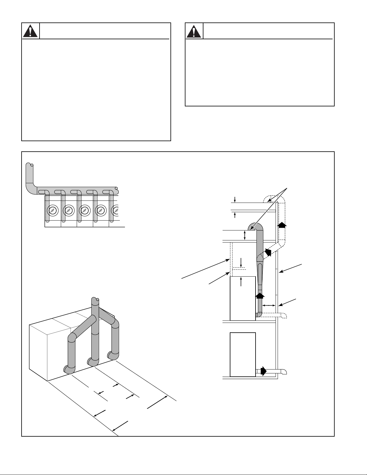
STEAM REQUIREMENTS (Steam Drying Tumblers)
The size of the steam service pipe is dependent upon
many variables (length, tees, high pressure system, low
pressure system, etc.). Specific pipe size information
should be obtained from the steam system supplier or a
qualified steam fitter.
1. Refer to F igur es 13, 14, and 15 for proper steam pipe
configurations.
2. To prevent condensate draining from headers to
tumbler, piping should ha v e a minimum 12 inch rise
(30.5 cm) above respective header. Do not make
steam connection to header with a horizontal or
downward facing tee or elbow.
3. Whenever possible, horizontal runs of steam lines
must drain, by gravity, to respective steam header.
Water pockets, or an improperly drained steam
header will provide wet steam, causing improper
operation of tumbler . If pockets or improper drainage
cannot be eliminated, install a by-pass trap to drain
condensate from the low point in the steam header to
the return.
4. In both steam supply and steam return line, it is
recommended that each have a pipe union and globe
valve. This will enable you to disconnect the steam
connections and service the tumbler while your plant
is in operation.
5. Before connecting trap and check valve to tumbler,
open shutoff valve in steam supply line and allow
steam to flow through tumbler to flush out any dirt
and scale from tumbler. This will assure proper
operation of trap when connected.
6. After flushing system, install vacuum breaker , bucket
trap (with built-in strainer) and check valve. For
successful operation of tumbler, install trap 18 inches
(45.7 cm) below coil and as near to the tumbler as
possible. Inspect trap carefully for inlet and outlet
markings and install according to trap manufacturer's
instructions. If steam is gravity returned to boiler,
omit trap but install vacuum breaker and check v alve
in return line near tumbler.
PIPING RECOMMENDATIONS
1. Trap each steam coil individually. Always keep the
trap clean and in good working condition.
2. When tumbler is on the end of a line of equipment,
extend header at least 4 feet (1.2 m) beyond tumbler.
Install shutoff v alve, union, check valve and by -pass
trap at end of line. If gravity return to boiler, omit
trap.
3. Insulate steam supply and return line for safety of
operator and safety while servicing tumbler.
4. Keep tumbler in good working condition. Repair or
replace any worn or defective parts.
NOTE: Steam heated tumbler models are not
certified by the American Gas Association or the
Canadian Gas Association.
WARNING
The flexible steam hoses connecting the
coil outlet connections and steam traps
must have a minimum of 172 psig (12.04
kg/cm2) (pounds per square inch gauge)
working pressure. A shutoff v alve m ust be
installed downstream from each steam
trap so the condensate return line can be
isolated in event a steam trap requires
maintenance.
W064
STEAM VALVE ELECTRICAL
CONNECTIONS
Refer to wiring diagram for steam valve electrical
connections in J-Box.
7. Install union and shutoff valve in return line and
make final pipe connections to return header.
M413620
37
Page 40

INSTALLING STEAM SOLENOID
VALVE AND MAKING STEAM INLET
CONNECTIONS
INSTALLING STEAM TRAP AND
MAKING CONDENSATE RETURN
CONNECTIONS
High pressure machines require a (constant) 80 to 100
psig (pounds per square inch gauge) (5.62 to 7.03 kg/s q.
cm) steam service for optimum operation. Low pressure
machines require a (constant) 10 to 15 psig (pounds per
square inch gauge) (.70 to 1.05 kg/sq. cm) steam service
for optimum operation. The following steps outline the
procedure for installing the steam solenoid valve and
connecting the steam service.
a. Install a manual shut-of f gate v alv e in the condensate
return line after the steam trap for each coil.
b. Connect the steam solenoid valve to the related steam
coil inlet connection with nipples, flex hoses, unions,
and tee. See Figures 13, 14, and 15 for typical
installations.
c. Install a gate shut-off valve in the steam supply line.
Connect the shut-off gate valve outlet to th e solenoid
steam valve inlet connection. See F igures 13, 14, and
15 for typical installations.
WARNING
The flexible steam hoses connecting the
solenoid steam valve to the coil inlets
must have a 125 psig (pounds per square
inch gauge) (8.79 kg/sq. cm) working
pressure. A shut-off gate valve must be
installed upstream from the solenoid
steam valve. This way, steam can be shut
off for maintenance purposes, or in the
event the hose ruptures.
The steam solenoid valve must be
supported so minimum load is exerted on
the steam coil inlet connections.
W065
The steam trap must be installed and the coil outlet
connections must be connected to the condensate return
lines. The following steps outline the procedure for
installing the steam trap and connecting the condensate
return lines. See Figures 13, 14, and 15 for typical
installations.
a. Connect a flexible hose to each steam coil outlet.
b. Install a strainer to the ends of each flexible hose.
c. Install a steam trap to each strainer.
IMPORTANT: Steam trap must be installed a
minimum of 10 inches (25.4 cm) below the steam coil
outlet connections.
d. Install a gate shut-off valve to each steam trap.
e. Connect to the condensate return lines.
WARNING
The flexible steam hoses connecting the
coil outlet connections and steam traps
must have a minim um of 125 psig (pounds
per square inch gauge) (8.79 kg/sq. cm.)
working pressure. A shutoff gate valve
must be installed downstream from each
steam trap so the condensate return line
can be isolated in event a steam trap
requires maintenance.
Each steam trap must be supported so
minimum load is exerted on the coil outlet
connection.
W066
38
M413620
Page 41

STEAM REQUIREMENTS
For 30, 50, and 75 Pound Steam DryingTumblers Only
NOTE: See Table 4 for sizing of steam
lines. Piping must also be sized
accordingly for length of runs, and
number of elbows.
SUPPLY
RETURN
12" (30.5 cm)
RISERS
UNION
CHECK
STEAM
BONNET
SOLENOID
VALVE
(Supplied with
machine)
VACUUM
BREAKER
CONDENSATE
RETURN LINE
FROM
SUPPLY LINE
VALVE
TRAP WITH
BUILT-IN
STRAINER
CHECK
VALVE
GATE
VALVE
Figure 13
TUMBLER
MODEL
STEAM PRESSURE
(PSI)
MINIMUM PIPE
DIAMETER
STEAM TRAP SIZE
(Pounds Condensate/Hour)
30CSL/50CSL/75CSL 7-15 3/4" (1.9 cm) 140
30CSH 80-100 3/4" (1.9 cm) 140
50CSH/75CSH 80-100 3/4" (1.9 cm) 16 0
T221IE3H
M413620
Table 4
39
Page 42

STEAM REQUIREMENTS
For 120 Pound Steam Drying Tumblers Only
NOTE: Sizing of pipe diameters is shown for
steam at rated pressure of 120 psi. Pipe diameter
needs to be increased accordingly if pressure is
less than 125 psi, see Table 5. Piping must also be
sized accordingly for length of runs, and number
of elbows.
STEAM
BONNET
= 3/4" DIAMETER PIPE
SUPPLY
RETURN
SHUT-OFF
VALVE
UNION
CHECK
VALVE
VACUUM
BREAKER
12" (30.5 cm)
RISERS
SHUT-OFF
VALVE
TRAP WITH
BUILT-IN
STRAINER
40
SOLENOID
VALVE
(Supplied with
machine)
VACUUM
BREAKER
CONDENSATE
RETURN LINE
FROM
SUPPLY LINE
CHECK
VALVE
Figure 14
TUMBLER
MODEL
STEAM PRESSURE
(PSI)
MINIMUM PIPE
DIAMETER
STEAM TRAP SIZE
(Pounds Condensate/Hour)
120CSH 120 – 125 1" (2.5 cm) 345
120CSH 60 – 120 1" (2.5 cm) 345
120CSH 35 – 60 1-1/4" (3.2 cm) 345
Table 5
T221IE3I
M413620
Page 43

STEAM REQUIREMENTS
For 170 Pound Steam Drying Tumblers Only
NOTE: Sizing of pipe diameters is shown for
steam at rated pressure of 120 psi. Pipe
diameter needs to be increased accordingly if
pressure is less than 125 psi, see Table 6.
Piping must also be sized accordingly for
length of runs, and number of elbows.
= 3/4" DIAMETER PIPE
= 1" DIAMETER PIPE
SUPPLY
RETURN
SHUT-OFF
VALVE
SOLENOID VALVE
(Supplied with
machine)
12" (30.5 cm)
RISERS
UNION
CHECK
VALVE
STEAM
BONNET
VACUUM
BREAKER
CONDENSATE
RETURN LINE
FROM
SUPPLY LINE
VACUUM
BREAKER
CHECK
VALVE
TRAP WITH
BUILT-IN
STRAINER
Figure 15
TUMBLER
MODEL
STEAM PRESSURE
(PSI)
MINIMUM PIPE
DIAMETER
STEAM TRAP SIZE
(Pounds Condensate/Hour)
170CSH 110 – 125 1" (2.5 cm) 517
170CSH 60 – 110 1-1/4" (3.2 cm) 517
170CSH 35 – 60 1-1/2" (3.8 cm) 517
SHUT-OFF
VALVE
T220IE3E
M413620
Table 6
41
Page 44

ELECTRICAL REQUIREMENTS
WARNING
To reduce the risk of electric shock, fire, explosion, serious injury or death:
• Disconnect electric power to the tumbler before servicing.
• Close gas shut-off valve to gas tumbler before servicing.
• Close steam gate valve to steam tumbler before servicing.
• Never start the tumbler with any guards/panels removed.
• Whenever ground wires are remo ved during servicing, t hese ground wires m ust be reconnected
to ensure that the tumbler is properly grounded.
WARNING
To reduce the risk of fire and electric shock, check with a qualified serviceman for proper
grounding procedures. Improper connection of the equipment grounding conductor may
result in a risk of electric shock.
To reduce the risk of fire and electric shock, if electrical supply is coming from a three
phase service, DO NOT connect a “High Leg” or “Stinger Leg” to a single phase machine.
On a three phase machine, if there is a “High Leg” or “Stinger Leg” it should be
connected to L3.
W002
W068
W069
GROUNDING INSTRUCTIONS
This drying tumbler must be grounded. In the event of
malfunction or breakdown, grounding will reduce the
risk of electric shock by providing a path of least
resistance for electric current. This tumbler must be
connected to a grounded metal, permanent wiring
system; or an equipment grounding conductor must be
run with the circuit conductors and connected to the
appropriate ground location.
WARNING
All electrical connections should be
made by a qualified electrician.
To reduce the risk of electrical shock, deenergize the electrical circuit being
connected to the tumbler before making
any electrical connections. Never attempt
to connect a live circuit.
W070
NOTE: To ensure protection against shock, this
tumbler MUST be electrically grounded in
accordance with the local codes, or in the absence of
local codes, with the latest edition of the National
Electrical Code ANSI/NFPA No. 70. In Canada the
electrical connections are to be made in accordance
with CSA C22.1 latest edition Canadian Electrical
Code, Part I and/or local codes. Electrical work
should be done by a qualified electrician.
CAUTION
Label all wires prior to disconnection
when servicing controls. Wiring errors
can cause improper and dangerous
operation. Verify proper operation after
servicing.
W071
42
M413620
Page 45

The following steps outline the procedure for connecting
the electrical service to the tumbler.
3. Check the electrical service phase sequence (three
phase only) as follows:
NOTE: The wiring diagram is supplied in material
packet in cylinder.
1. Install a circuit breaker as close to the tumbler as
possible. If more than one tumbler is being installed,
a disconnect switch or circuit breaker should be
provided for each. This will make it possible to
disconnect each tumbler for maintenance purposes.
2. Connect the conduit-encased leads to the disconnect
switch, or circuit breaker. Connect the wire leads to
the appropriately labeled terminal on the terminal
block. The ground wire must be connected to the
ground connection as shown in Figure 16.
ELECTRICAL SERVICE
(Gas & Steam Models)
a. Energize the electrical service (on reversing
tumblers, ensure non-reversing is selected)and
momentarily start the tumbler. Check the direction
of the cylinder rotation. If the cylinder rotates
clockwise (viewed from the front), the phase
sequence is correct. If the cylinder rotates
counterclockwise, proceed with step “b”.
NOTE: On reversing tumblers, the fan motor should
also rotate clockwise (viewed from the front) on all
models except 120 pound, 170 pound and 634 models.
The fan motor on 120 pound, 170 pound and 634
models rotates counterclockwise (viewed from the
front).
b. Disconnect and reverse any two leads at
connections.
ELECTRICAL SERVICE
(Electric Models)
CONTACTOR
BOX
ACCESSORY
BOX
GROUND LUG
(Electric Models)
FUSES
GROUND SCREW
(Gas & Steam Models Only)
T224SE3A
Figure 16
M413620
43
Page 46

JUMPER CONFIGURATION
INSTRUCTIONS (OPL MICRO
CONTROL MODELS ONLY)
RING FERRITE INSTALLATION
(GAS AND STEAM OPL MICRO
CONTROL MODELS ONLY)
Changing the transformer configuration jumper is
required if any of the following apply:
• You have 208V service and are connecting a gas or
steam model rated for 208 or 240V.
• You have 415V service and are connecting a gas or
steam model rated for 380 or 415V.
To configure your 208V or 240V tumbler for 208V
operation, you must remove the 240V configuration
jumper located in the contactor box and replace it with
the 208V jumper supplied with the information packet.
This must be done prior to supplying po wer to machine.
Failure to install proper configuration jumper may result
in damage to sensitive electronic controls and may void
warranty.
To configure your 380V or 415V tumbler for 415V
operation, you must remove the 380V configuration
jumper located in the contactor box and replace it with
the 415V jumper supplied with the information packet.
This must be done prior to supplying po wer to machine.
Failure to install proper configuration jumper may result
in damage to sensitive electronic controls and may void
warranty.
The ring ferrite provided in the information packet must
be installed over the power leads during connection of
electrical service. The ferrite protects the sensitive
electronic controls from destructive electrical
disturbances which may be present on power lines to the
machine. Failure to properly install the ring ferrite may
result in damage to the electronic controls and will void
control warranty.
Installation Instructions:
1. Immediately after connection of power leads and
before applying power to machine, locate each of the
incoming service leads including ground.
2. Snap the ring ferrite closed over all of the service
leads inside of the contactor box as shown. It is
important that the ferrite ring be installed inside the
contactor box as shown. Do not install the ferrite
outside of the box or other area. Make sure that
service leads are in the center of the ferrite before
closing the ring so not to pinch or damage leads.
CONTACTOR
BOX
JUMPER
Figure 17
FERRITE
RING
T225SE1A
44
M413620
Page 47

ELECTRICAL REQUIREMENTS
For 30 Pound (28" wide) Tumblers
NOTE: Minimum wire sizes are obtained from Canadian Electrical Code and are intended for use as a guideline
only. Electrical connections should be made only by a qualified electrical contractor in accordance with all
applicable local and national requirements.
NOTE: DO NOT use aluminum wire.
Heat Source
Gas 120/60/1 L1, Neutral, and ground
Gas 208-240/60/1 L1, L2, Neutral, and ground
Gas 240/50/1 L1, Neutral, and ground
Gas 120/50/1 L1, Neutral, and ground
Electric 208/60/1 L1, L2, and ground
Electric 240/60/1 L1, L2, and ground
Electric 240/50/1 L1, Neutral, and ground
Electric 208/60/3 L1, L2, and ground
Electric 240/50/3 L1, L2, L3, and ground
Electric 240/60/3 L1, L2, L3, and ground
Electric 380/50/3 L1, L2, L3, Neutral, and ground
Electric 415/50/3 L1, L2, L3, Neutral, and ground
Electric 480/60/3 L1, L2, L3, and ground
Amp Rating 104 AMP 92 AMP 62 AMP 55 AMP 27 AMP 91 AMP 55 AMP 34 AMP 31 AMP
Circuit Breaker 125 AMP 100 AMP 70 AMP 60 AMP 30 AMP 100 AMP 60 AMP 40 AMP 35 AMP
Poles 223332333
Minimum Wire Size
Per Canadian Elec.
Code C22.1
Electrical Specs
ELECTRIC DRYING TUMBLERS
208V
60 HZ
1 PH
1 AWG 2 AWG 4 AWG 6 AWG 10 AWG 2 AWG 6 AWG 8 AWG 8 AWG
240V
60 HZ
1 PH
208V
60 HZ
3 PH
Wires Required and Terminal Block Connections
Table 7
240V
60 HZ
3 PH
480V
60 HZ
3 PH
240V
50 HZ
1 PH
240V
50 HZ
3 PH
380V
50 HZ
3 PH
415V
50 HZ
3 PH
Table 8
GAS DRYING TUMBLERS
120V 1 Phase
60 Hz.
Minimum Wire Size Per
Canadian Elec. Code C22.1
Disconnect Switch 15 AMP
Fusetron 15 AMP
Circuit Breaker 15 AMP 15 AMP 15 AMP 15 AMP
No. of Poles 1222
M413620
14 AWG 16 AWG 16 AWG 14 AWG
208/240V 1 Phase
60 Hz.
USE CIRCUIT BREAKER ONLY
Table 9
240V 1 Phase
50 Hz.
120V 1 Phase
30 Hz.
45
Page 48

ELECTRICAL REQUIREMENTS
For 30 Pound (31.5" Wide) Tumblers
NOTE: Minimum wire sizes are obtained from Canadian Electrical Code and are intended for use as a guideline
only. Electrical connections should be made only by a qualified electrical contractor in accordance with all
applicable local and national requirements.
NOTE: DO NOT use aluminum wire.
Heat Source Serial Plate Voltage
Steam CSL 120V/60Hz/1ph L1, Neutral and ground * 20 Amps 1 12 AWG
Gas & CSH 120V/60Hz/1ph L1, Neutral and ground * 15 A mps 1 14 AWG
Gas & Steam 208 or 240V/60Hz/1ph L1, L2 and ground * 15 Amps 2 14 AWG
Gas & Steam 230-240V/50Hz/1ph L1, Neutral and ground * 15 Amps 1 14 AWG
Gas & Steam 208 or 240V/60Hz/3ph L1, L2, L3, and ground * 15 Amps 3 14 AWG
Gas & Steam 380 or 415V/50Hz/3ph L1, L2, L3, and ground * 15 Amps 3 14 AWG
Gas & Steam 460-480V/60Hz/3ph L1, L2, L3, and ground * 15 Amps 3 14 AWG
Electric 208V/60Hz/1ph L1, L2, and ground 104 Amps 125 Amps 2 0 AWG
Electric 240V/60Hz/1ph L1, L2, and ground 92 Amps 100 Amps 2 2 AWG
Electric 240V/50Hz/1ph L1, Neutral and ground 90 Amps 100 Amps 1 2 AWG
Electric 208V/60Hz/3ph L1, L2, L3, and ground 62 Amps 70 Amps 3 4 AWG
Electric 240V/60Hz/3ph L1, L2, L3, and ground 55 Amps 60 Amps 3 4 AWG
Electric 240V/50Hz/3ph L1, L2, L3, and ground 53 Amps 60 Amps 3 4 AWG
Electric 380V/50Hz/3ph L1, L2, L3, and ground 33 Amps 40 Amps 3 8 AWG
Electric 415V/60Hz/3ph L1, L2, L3, and ground 30 Amps 35 Amps 3 8 AWG
Electric 480V/60Hz/3ph L1, L2, L3, and ground 28 Amps 35 Amps 3 8 AWG
* Current Ratings vary slightly depending on model, see serial plate.
Terminal Block
Connections Required
Rated
Current
Breaker
Rating
Breaker
Poles
Recommended
Wire Size
Table 10
46
M413620
Page 49

ELECTRICAL REQUIREMENTS
For 50 Pound Tumblers
NOTE: Minimum wire sizes are obtained from Canadian Electrical Code and are intended for use as a guideline
only. Electrical connections should be made only by a qualified electrical contractor in accordance with all
applicable local and national requirements.
NOTE:
Heat Source Serial Plate Voltage
Gas & Steam 120V/60Hz/1ph L1, Neutral and ground * 20 Amps 1 12 AWG
Gas & Steam 208 or 240V/60Hz/1ph L1, L2, and ground * 15 Amps 2 14 AWG
Gas & Steam 230-240V/50Hz/1ph L1, Neutral and ground * 15 Amps 1 14 AWG
Gas & Steam 208 or 240V/60Hz/3ph L1, L2, L3, and ground * 15 Amps 3 14 AWG
Gas & Steam 380 or 415V/50Hz/3ph L1, L2, L3, and ground * 15 Amps 3 14 AWG
Gas & Steam 460-480V/60Hz/3ph L1, L2, L,3 and ground * 15 Amps 3 14 AWG
Electric 240V/50Hz/1ph L1, Neutral and ground 91 Amps 100 Amps 1 2 AWG
Electric 208V/60Hz/3ph L1, L2, L3, and ground 88 Amps 100 Amps 3 2 AWG
Electric 240V/60Hz/3ph L1, L2, L3, and ground 78 Amps 90 Amps 3 2 AWG
Electric 240V/50Hz/3ph L1, L2, L3, and ground 78 Amps 90 Amps 3 2 AWG
Electric 380V/50Hz/3ph L1, L2, L3, and ground 50 Amps 60 Amps 3 4 AWG
Electric 415V/60Hz/3ph L1, L2, L3, and ground 46 Amps 60 Amps 3 4 AWG
Electric 480V/60Hz/3ph L1, L2, L3, and ground 38 Amps 50 Amps 3 6 AWG
* Current Ratings vary slightly depending on model, see serial plate.
DO NOT use aluminum wire
.
Terminal Block
Connections Required
Rated
Current
Breaker
Rating
Breaker
Poles
Recommended
Wire Size
Table 11
ELECTRICAL REQUIREMENTS
For 75 Pound Tumblers
NOTE: Minimum wire sizes are obtained from Canadian Electrical Code and are intended for use as a guideline
only. Electrical connections should be made only by a qualified electrical contractor in accordance with all
applicable local and national requirements.
NOTE: DO NOT use aluminum wire.
Heat Source Serial Plate Voltage
Gas & Steam 120V/60Hz/1ph L1, Neutral and ground * 20 Amps 1 12 AWG
Gas & Steam 208 or 240V/60Hz/1ph L1, L2, and ground * 15 Amps 2 14 AWG
Gas & Steam 230-240V/50Hz/1ph L1, Neutral and ground * 15 Amps 1 14 AWG
Gas & Steam 208 or 240V/60Hz/3ph L1, L2, L3, and ground * 15 Amps 3 14 AWG
Gas & Steam 380 or 415V/50Hz/3ph L1, L2, L,3 and ground * 15 Amps 3 14 AWG
Gas & Steam 460-480V/60Hz/3ph L1, L2, L3, and ground * 15 Amps 3 14 AWG
Electric 208V/60Hz/3ph L1, L2, L3, and ground 88 Amps 100 Amps 3 2 AWG
Electric 240V/60Hz/3ph L1, L2, L3, and ground 78 Amps 90 Amps 3 2 AWG
Electric 240V/50Hz/3ph L1, L2, L3, and ground 78 Amps 90 Amps 3 2 AWG
Electric 380V/50Hz/3ph L1, L2, L3, and ground 50 Amps 60 Amps 3 4 AWG
Electric 415V/60Hz/3ph L1, L2, L3, and ground 46 Amps 60 Amps 3 4 AWG
Electric 480V/60Hz/3ph L1, L2, L3, and ground 38 Amps 50 Amps 3 6 AWG
* Current Ratings vary slightly depending on model, see serial plate.
Terminal Block
Connections Required
Rated
Current
Breaker
Rating
Breaker
Poles
Recommended
Wire Size
M413620
Table 12
47
Page 50

ELECTRICAL REQUIREMENTS
For 120 Pound Tumblers
NOTE: Minimum wire sizes are obtained from Canadian Electrical Code and are intended for use as a guideline
only. Electrical connections should be made only by a qualified electrical contractor in accordance with all
applicable local and national requirements.
NOTE: DO NOT use aluminum wire.
Heat Source Serial Plate Voltage
Gas & Steam 208-230V/60Hz/3ph L1, L2, L3, and ground * 10 Amps 3 14 AWG
Gas & Steam 380-415V/50Hz/3ph L1, L2, L3, and ground * 10 Amps 3 14 AWG
Gas & Steam 460-480V/60Hz/3ph L1, L2, L3, and ground * 10 Amps 3 14 AWG
* Current Ratings vary slightly depending on model, see serial plate.
Terminal Block
Connections Required
Rated
Current
Breaker
Rating
Breaker
Poles
Recommended
Wire Size
Table 13
ELECTRICAL REQUIREMENTS
For 170 Pound Tumblers
NOTE: Minimum wire sizes are obtained from Canadian Electrical Code and are intended for use as a guideline
only. Electrical connections should be made only by a qualified electrical contractor in accordance with all
applicable local and national requirements.
NOTE: DO NOT use aluminum wire.
Heat Source Serial Plate Voltage
Gas & Steam 208-230V/60Hz/3ph L1, L2, L3, and ground * 30 Amps 3 10 AWG
Gas & Steam 380-415V/50Hz/3ph L1, L2, L3, and ground * 20 Amps 3 12 AWG
Gas & Steam 460-480V/60Hz/3ph L1, L2, L3, and ground * 15 Amps 3 14 AWG
* Current Ratings vary slightly depending on model, see serial plate.
Terminal Block
Connections Required
Rated
Current
Breaker
Rating
Breaker
Poles
Recommended
Wire Size
48
Table 14
M413620
Page 51

ACCESSORY TIMING CAM INSTALLATION
(Coin Meter Models)
The Drying Tumbler is shipped with two accessory cams
which allow you to change your vending times.
The coin slide tumbler accumulator will have a 60 minute
timer motor. The accumulator will operate with a two pin
cam (30 minutes). The cams furnished with the tumbler
will be three pin (20 minutes) and four pin (15 minutes).
The 25¢ meter will have a 60 minute timer motor. The
timer will operate as shown in Table 15:
No. of Pins in Cam Cycle Length (Minutes)
6
5
4
10
12
15
Table 15
Cams that allow other timer increments are available
through your distributor.
T o figure time increments, use this formula: Timer Motor
Speed (60) divided by number of pins on cam = Cycle
Length (minutes). Cams are available with 1 to 12 pins.
Example: 60 ÷ 5 (Pin cam) = 12 minute cycle.
INSTALLATION OF NEW TIMING CAM
1. Insert drive into timing cam with wide prong in wide
hole of cam.
2. Position timing cam and drive fork over the timer
shaft, aligning the timer flat with the drive fork and
the “V” notch with one of the ratchet teeth.
3. Press timing cam down firmly to seat timing cam
onto the motor shaft.
LINE UP NOTCH
TO CLEAR RATCHET
TOOTH
LIFT GENTLY
WITH NARROW
BLADE
T039IE1A
REMOVAL OF EXISTING TIMING CAM
1. Rotate cam by hand until “V” notch lines up beneath
the ratchet tooth see Figure 18.
2. Insert narrow screwdriver under nylon cam, close to
the clock shaft. Lift gently off shaft. Make sure that
pressure is directed upward and that the “V” notch
clears the ratchet tooth.
Figure 18
4. Remove all accumulated time by turning cam
counterclockwise until switch shuts off. Apply
moderate clockwise pressure to fully seated timing
cam and drive against the timing motor shaft. Meter
must be advanced electrically for one cycle before an
accurate measure of time can be made.
M413620
49
Page 52

PRELIMINARY OPERATING CHECKS
1. Remove or open all panels and check accessible
bolts, nuts, screws, terminals and fittings for
tightness.
2. Check V -belt tension and adjust if necessary . Refer to
appropriate paragraphs in Section IV.
3. Steam tumblers: Open the steam service shut-off
valves.
4. After performing the previous checks, start the
tumbler by pressing START (hold for approximately
three seconds). Release the start button and open the
cylinder door. The cylinder should stop rotating
within seven seconds after the door is opened a
maximum of two inches (5.01 cm) plus or minus ¹⁄₄
inch (.63 cm). If it does not, adjust the cylinder door
interlock. Refer to the appropriate paragraph in
Section IV.
5. Gas tumblers: Start the tumbler and check the burner
flame. Adjust the gas inlet shutter as required. Refer
to the appropriate paragraph in Section IV.
IMPORTANT: The one wire igniter Instant
Electronic Ignition system will attempt to light the gas
by sparking for approximately 15 seconds (5 seconds
for 2 wire igniters). If gas ignition does not take place
within 15 seconds (5 seconds for 2 wire igniters) the
Instant Electronic Ignition control will go into safety
lockout and the valve will no longer open until Instant
Electronic Ignition control is reset. To reset Instant
Electronic Ignition control, remove power from
control by opening and closing the tumbler Door. If
condition persists, check, that the gas shut-off valve is
in “on” position and that the gas service is properly
connected. If condition still persists, remove tumbler
from service.
6. Load the cylinder with a full load of clothes or clean
rags and run to remove oil or dirt from cylinder.
7. Gas and electric tumblers: Check the air flow switch
operation by opening the lint panel. The heating
systems should shut off when the lint panel is opened
a maximum of 1-1/2 inches (3.81 cm).
WARNING
The tumbler must not be operated if the air
flow switch does not operate properly.
Faulty air flow s witch operation ma y cause
an explosive gas mixture to collect in the
tumbler.
W072
The air flow switch operation may be affected by
shipping tape still in place, lack of make-up air, or an
obstruction in the exhaust duct. These should be checked
and the required corrective action taken before
attempting to adjust the air flow switch. T o adjust the air
flow switch refer to appropriate paragraph in Section IV.
50
M413620
Page 53

FINAL OPERATING CHECKS
OPL MICRO-CONTROL TUMBLER
Refer to OPL micro-control section to check control for
proper operation.
MANUAL DUAL TIMER TUMBLER
(FIGURE 19)
1. Set the TEMPERATURE selector to the desired
temperature, and set the DRYING and COOLING
selectors to maximum.
2. Press the PUSH-TO-START button in and hold it in
for approximately three seconds. The motor will
start, the heat system will come on and the DRYING
indicator will light.
3. During the drying period the DRYING selector
rotates counterclockwise. When the DRYING
selector reaches “0” the heat system will shut off, the
DR YING indicator will go out and the COOLING
indicator will light.
During the cooling period the COOLING selector rotates
to the left. When the COOLING selector reaches “0” the
motor will stop and the COOLING indicator will go out
indicating the end of the cycle.
COIN OPERATED TUMBLER
(FIGURE 20)
1. Set the TEMPERATURE selector to the desired
temperature.
2. Insert required number of coins in the coin slot and
turn the knob fully clockwise and release it. The
RUN indicator (option) will light.
For Coin Slide Models — Place required number of
coins in coin slide and push slide in as far as possible,
then release.
3. Press the PUSH-TO-START button in and hold it in
for approximately three seconds. The motor will start
and the heat circuit will come on.
4. An automatic preset 2-1/2 minute cool-down period
occurs near the end of the cycle. During this period
the heat system is off and encompassing air circulates
through the load to cool it.
5. When the coin metered time expires, the cycle is
completed.
M413620
51
Page 54

TEMPERATURE
SELECTOR
MANUAL DUAL TIMER
DURABLE PRESS CONTROL PANEL
TEMPERATURE
HIGH LOW
MED
PUSH TO START
COOLING
INDICATOR
COOLING
10
5
DRYING
INDICATOR
DRYING
25
20
15
0
15
30
0
5
10
T020IE3A
PUSH-TO-START
BUTTON
Figure 19
TEMPERATURE
SELECTOR
HIGH
*SINGLE COIN-OPERATED
COTTON
DURABLE PRESS CONTROL PANEL
PUSH-TO-START
BUTTON
* DUAL COIN OPERATED PANELS HAVE SLOTS FOR TWO COINS.
EACH COIN OPERATES THE TUMBLER FOR A SPECIFIC TIME.
Figure 20
RUN
INDICATOR
TEMPERATURE
MED
MIXED
PUSH TO START
COOLING
TIMER
SELECTOR
LOW
PERMA
PRESS
DRYING
TIMER
SELECTOR
SINGLE AND DUAL COIN
METER COIN SLOT AND KNOB
T019IE3A
52
TEMPERATURE
SELECTOR
PUSH-TO-START
BUTTON
RUN
INDICATOR
COIN
SLIDE
T004IE3A
Figure 21
M413620
Page 55

SECTION IV
Adjustments
MAIN GAS BURNER AIR SHUTTER
All Gas Models
NOTICE: Air inlet shutters on the burner must be
adjusted so sufficient air is metered into the system
for proper combustion and maximum efficiency.
Before adjusting the inlet shutters be sure that all lint
is removed from lint compartment and lint screen.
Air shutter adjustments will vary from lo cation to
location and will depend on the vent system, number of
units installed, make-up air and line gas pre ss ure.
Opening the shutter increases the amount of primary air
supplied to the burner while closing the shutter decreases
the primary air supply. Adjust air shutter as follows:
1. Open the access panel.
2. Start the tumbler and check the flame pattern. Correct
air and gas mixture is indicated if the flame pattern is
primarily blue, with small yellow tips, and bends to
the right of the heater section. (See Figures 22 and
23.) Too little air is indicated if the flame is yellow,
lazy and smokey.
3. To adjust the air shutter, loosen air inlet shutter
adjusting screw, see Figures 22 and 23.
4. Open or close air shutter as necessary to obtain
proper flame intensity .
5. After air shutter is adjusted for pr oper flame, tighten
air shutter adjusting screw securely. Control panel
may have to be removed temporarily to loosen air
shutter screws to adjust shutter.
6. If the shutter is correctly adjusted, but the flame
pattern is straight up, (see Figures 22 and 23),
insufficient primary air is flowing through the
tumbler and airflow switch is improperly set. A flame
pattern that flares to the right and left (see Figur es 22
and 23) indicates no air is flowing through the
tumbler.
M413620
53
Page 56

FOR 30, 50 AND 75 POUND TUMBLERS
PROPER
AIR FLOW
T048SE3A
AIR SHUTTER
ADJUSTING
SCREWS
INSUFFICIENT
AIR FLOW
AIR SHUTTER
ADJUSTING
SCREWS
T047SE3A
NO AIR FLOW
T049SE3A
AIR SHUTTER
ADJUSTING
SCREWS
NOTE: The burner configuration will differ between the 30, 50 and 75 pounds tumblers, but the flame
pattern will be as shown.
Figure 22
FOR 120 AND 170 POUND TUMBLERS
PROPER AIR FLOW
AIR SHUTTER
ADJUSTING SCREW
T211IE3A
INSUFFICIENT AIR FLOW
AIR SHUTTER
ADJUSTING SCREW
T212IE3A
NO AIR FLOW
AIR SHUTTER
ADJUSTING SCREW
54
T210IE3A
Figure 23
M413620
Page 57

AIR FLOW SWITCH
For 30, 50, and 75 Pound Gas and Electric Tumblers
The air flow switch (located on the rear of tumbler Figure
24) is set at the factory for proper operation. Steam models
do not have an airflo w switch. However, if there is a
problem with the switch, it should be adjusted as follows:
NOTICE: Control panel must be in place and access
door closed before attempting to adjust air flow
switch.
IMPORTANT: Air flow switch disc must remain
closed during operation. If it opens and closes during
the drying cycle, this indicates insufficient air flow
through the tumbler. If switch remains open, or pops
open and closed during the cycle, the heating system
will shut off. The cylinder and fan will continue to
operate even though the air flow switch is
malfunctioning.
WARNING
To reduce the risk of fire, air flow switch
operation may be affected by a clogged
lint screen, lack of make-up air,
obstructions in the vertical recirculation
stack or in the customer installed main or
collector ducts. These conditions must
be checked and necessary corrections
made before adjusting air flow switch.
Always adjust air flow at installation.
W073
The air flow switch operation is controlled by the
counterweight position in the shaft. Moving the
counterweight either increases or decreases air flow
switch sensitivity. The counterweight should be adjusted
so the air flow will force the disc away from the cabinet
when the lint panel is opened 6 inches (15.24 cm) with a
full load. Adjust the air flow switch as follows:
1. Load the tumbler. This adjustment is much faster to
make with one person opening lint panel in front and
another adjusting the counterweight in the rear of
tumbler.
2. Start the tumbler. Open the lint panel 6 inches
(15.24 cm). The airflow disc sh ould move away
from the cabinet, opening the switch contacts and
shutting off the heat system. This indicates proper
operation and proper adjustment.
3. If switch is not opening as described in step “2”, it
should be adjusted so it is MORE sensitive. Depress
the spring clip and move counterweight to w ard disc.
Retest by opening lint panel and continue moving
counterweight toward disc until switch operates as
described in step “2”.
4. If switch opens BEFORE lint panel is opened the
proper distance, step “2”, it should be adjusted so it
is LESS sensitive. Depress the spring clip and move
counterweight away from the disc. Retest by opening
lint panel and continue moving counterweight away
from disc until switch operates as described in step
“2”.
AIR FLOW
SWITCH
COUNTERWEIGHT
M413620
MOUNTING
BRACKET
SWITCH
LEVER
DISC
SPRING
CLIP
Figure 24
REAR
PANEL OF
TUMBLER
AIR FLOW
SWITCH
VANE
LEVER
ARM
DISC
SWITCH
ADJUSTING
SCREWS
SCREW
SWITCH
LEVER
SPRING
CLIP
COUNTERWEIGHT
T041IE3A
55
Page 58

AIR FLOW SWITCH
For 120 and 170 Pound Tumblers
The air flow switch is located on the back of the tumbler,
see Figure 25 or 26. It consists of a small limit switch
wired in series with the gas control transformer. A vane,
which is pulled against the tumbler back by normal air
circulation, actuates the switch. When air circulation is
interrupted, (lint door open, clogged lint screen,
inadequate vent, etc.), the vane will not pull in and
energize the gas valve circuits.
IMPORTANT: The tumbler should not be operated if
the air flow switch flutters, turning the gas on and off
rapidly. This can be caused by improper vent, clogged
lint screen, fan motor turning in the wrong direction,
etc.
NOTICE: The access door must be closed before
attempting to adjust air flow switch.
IMPORTANT: Air flow switch vane must remain
closed drying operation. If it opens and closes during
the drying cycle, this indicates insufficient air flow
through the tumbler. If switch remains open, or pops
open and closed during the cycle, the heating system
will shut off. The cylinder and fan will continue to
operate even though the air flow switch is
malfunctioning.
NOTICE: Air flow switch operation may be affected
by a clogged lint screen, lack of make-up air, or
obstructions in the vertical recirculation stack or in
the customer installed main or collector ducts. These
conditions 2ust be checked and necessary corrections
made.
56
M413620
Page 59

AIR FLOW LIGHT
Only on 120 and 170 Pound Manual Timer Models
The light on the front control panel indicates when the air
flow through the tumbler is less th an normal. When this
light flickers on and off or stays on all the time, the
tumbler cannot operate properly. If cleaning the lint
screen does not correct the problem, other possibilities
include: Lint build-up in the exhaust line or discharge
vent, incorrect rotation of blower, lack of make-up air,
jammed back-draft damper, overloaded tumbler or
anything else that will reduce the air flow.
For 120 lb. Tumblers only.
AIR FLOW
SWITCH
FINAL DRIVE
EYE BOLT
REVERSING
MOTOR
3/4 H.P.
DRIVE
MOTOR
EYE BOLT
BLOWER
MOTOR
1 H.P.
The air flow light is wired to the normally close contact
of the air flow switch, so when the air flow switch flutters
or does not pull in, the light will advise the operator that
there is a problem, which should be corrected
immediately. It is normal for the light to come on for 2
seconds when the tumbler is started. It should go out
when the blower is up to speed.
For 170 lb. Tumblers only.
AIR FLOW
SWITCH
FINAL
DRIVE
EYE
BOLT
REVERSING
MOTOR
3/4 H.P.
DRIVE
MOTOR
EYE BOLT
Figure 25
BLOWER
MOTOR
3 H.P.
T173IE1B
T283IE1A
Figure 26
M413620
57
Page 60

CYLINDER DOOR SWITCH
For 30, 50, and 75 Pound Tumblers
The door switch should be adjusted so the cylinder stops
when door is opened two inches (5.08 cm), plus or minus
1/4 inch (.63 cm). This switch is a normally open switch
and is closed by the interlock rod when the door is closed.
If adjustment is required, refer to Figure 27 and proceed
as follows:
1. Close door and start tumbler, slowly open loading
door . Cylinder an d heat sy stem should shut of f when
door is open two inches (5.08 cm) plus or minus 1/4
inch (.63 cm).
2. Slowly close loading door. When door is two inches
from being fully closed, the tab should contact the
interlock rod and depress it enough to operate the
switch arm closing the switch with an audible
“click”.
3. If interlock rod does not depress enough to operate
the switch, bend tab on loading door OUTWARD one
eighth inch (.32 cm) and repeat steps “1” and “2”.
Bend tab outward an additional 1/8, inch (.32 cm) if
required to obtain proper rod movement and switch
operation.
4. If proper operation is not obtained by procedure
outlined in step “3”, unlock and open top panel and
remove control panel. Loosen the two adjusting
screws holding the switch to the bracket and move
switch 1/8, inch (.32 cm) toward the front of the
switch bracket and retighten the screws. Repeat steps
“1” and “2”. If switch and rod still do not have
sufficient movement, move switch forward an
additional 1/8 inch (.32 cm).
SWITCH
ARM
SWITCH
BRACKET
ADJUSTING
SCREWS
INTERLOCK
ROD
Figure 27
DOOR
SAFETY
SWITCH
TAB
T249IE1A
58
M413620
Page 61

CYLINDER DOOR SWITCH
For 120 and 170 Pound Tumblers
The door switch should be adjusted so that the cylinder
stops whenever the door is opened by 2 inches (5.1 cm),
plus or minus 1/4 inch (.6 cm). A switch is provided
inside of the front panel to gover n this operation. The
switch is activated by an adjustable bolt on the cylinder
door upper hinge that contacts the switch arm. If
adjustment is required, refer to Figur e 28 and proceed as
follows:
1. Slightly loosen the nut on the door switch activator
screw.
2. Using a 5/64" hex wrench, turn the door switch
activator screw in or out slightly as required.
3. Open the door and check the amount of door opening
before shutdown occurs. If not proper , repeat steps 1
and 2.
CYLINDER DOOR STRIKE
DOOR SWITCH ACTIVATE
SCREW AND NUT
T218IE1A
Figure 28
The door strike must be adjusted to have sufficient
tension to hold loading door closed against force of load
tumbling against it. Proper adjustment is when 8 to 15
pounds (35.6 N - 66.7 N) pull is required to open door.
If adjustment is required, refer to Figure 29 and proceed
as follows:
To adjust, open door, loosen jamnut and turn door strike
screw in or out as required. Retight en jamnut.
DOOR
STRIKE
ACORN
NUT
DOOR
LATCH
M413620
T048IE1A
Figure 29
59
Page 62

WARNING
To reduce the risk of electric shock, fire, explosion, serious injury or death:
• Disconnect electric power to the tumbler before servicing.
• Close gas shut-off valve to gas tumbler before servicing.
• Close steam gate valve to steam tumbler before servicing.
• Never start the tumbler with any guards/panels removed.
• Whenever ground wires are remo ved during servicing, t hese ground wires m ust be reconnected
to ensure that the tumbler is properly grounded.
BELT DRIVE
W002
Nonreversing Models (see
Proper tension is when the driv e V-belt can be depressed
approximately 1/2 inch (1.27 cm) by applying light
thumb pressure at a point midway between the sheave
and motor pulley.
1. Remove gu ard from rear of tumbler.
Figure 31
CHAIN DRIVE
Nonreversing Models (see
Proper tension is when the belt can be depressed
approximately 1/2 inch (1.27 cm) by applying light
thumb pressure at a point midway between the cylinder
sprocket and the idler sprocket.
IMPORTANT: After a tumbler has been in operation
over an extended period of time, a “HIGH POINT”
will develop on the cylinder drive sprocket through
use and wear. Turn the sprocket manually with drive
chain in place until this “high point” is at the top
center. The “high point” can be found by noticing
increased chain tension while slowly rotating the
cylinder sprocket manually.
Figure 30
)
2. To adjust belt tension, loosen idler housing bolts
holding idler housing assembly to the housing
support.
3. Position housing assembly by turning adjusting bolt
until proper belt tension is reached, then retighten
idler housing bolts.
4. Replace the guard on rear of tumbler.
)
1. Remove guard from rear of tumbler.
2. To adjust chain tension, loosen jamnut holding idler
sprocket to housing.
3. Move idler sprocket left or right until proper chain
tension is reached, then retighten the jamnut.
4. Replace the guard on rear of tumbler.
60
M413620
Page 63

BELT DRIVE
Reversing Models (see
Proper tension is when the drive belt can be depressed
approximately 1/2 inch (1.27 cm) by applying light
thumb pressure (approximately 5 pounds) at a point
midway between the sheave and motor pulley.
Proper tension is when each cylinder belt can be
depressed approximately 3/16 inch (.48 cm) by applying
light thumb pressure (approximately 5 pounds) at a point
midway between the sheave and the idler.
1. Remove guard from rear of tumbler.
2. To adjust cylinder belt tension, loosen idler housing
bolts holding idler housing assembly to the hous ing
support.
Figure 32
)
3. Position housing assembly by tur ning adjusting bolt
until proper belt tension is reached, then retighten
idler housing bolts.
NOTE: Adjusting the cylinder belt tension will
change the drive belt tension. Drive belt tension must
also be adjusted.
4. Loosen the locking bolt.
5. Loosen the adjusting nut and use the adjusting screw
to move the motor up or down.
6. Once proper belt tension is reached, retighten the
adjusting nut and locking bolt.
7. Replace the guard on rear of tumbler.
BELT DRIVE
120 and 170 Pound Reversing Models (see
WARNING
Figures 25 & 26
WARNING
)
To reduce the risk of serious injury or
death, disconnect power to the tumbler
before performing this operation.
W074
The drive assemblies consist of motors, belts, eyebolts,
and a step pulley.
The pulley diameters are sized to produce a cylinder
speed of 37-39 RPMS (120 lb .) or 29-31 RPMS (170 lb.).
The step pulley assembly is used for speed reduction as
well as a means of adjusting belt tension. The pulley
mounting plate is attached to the frame of the cabinet.
The frame mounting plate has vertically slotted holes
allowing up and down movement of the step pulley
mounting plate for belt adjustment.
Adjust the belt tension as follows:
1. Disconnect electrical power to the tumbler before
attempting any adjustments to the drive assemby.
2. Loosen the upper nut on the final drive eye-bolt
(Fig ures 25 & 26).
3. Rotate the lower nut of the final drive eye-bolt
clockwise until proper belt tension is achieved.
To reduce the risk of serious injury or
death, guard panel MUST be installed on
the rear of the tumbler after the belt
adjustment is made.
W075
4. Rotate upper nut clockwise against the lower nut in
order to lock it into place.
5. If necessary, adjust the drive motor belt tension eyebolt using the same procedure as steps 1-4. (Figures
25 & 26).
6. Adjust blower belt tension on 120 pound 50 Hz.
tumblers and all 170 pound tumblers using the same
procedure as in steps 1-4.
NOTE: Proper tension for new belts is 45-55 pounds
for the motor belt and 55-65 pounds for the final
drive, measured with a Borroughs Belt Tension
Gauge. Using a Browning Belt Tension Gauge, the
motor belt deflection should be 5/16 inch at five
pounds pressure, and final drive belt deflection
should be 1/4 inch at five pounds pressure.
Belts should not slip or make any noise when starting up
under normal load.
M413620
61
Page 64

NONREVERSING
CHAIN DRIVE MODELS
SHEAVE
ONE HALF INCH
(1.27 cm)
DEFLECTION
CYLINDER
DRIVE CHAIN
WARNING! DO NOT
OPERATE WITHOUT
GUARDS IN PLACE.
CYLINDER
SPROCKET
IDLER
SPROCKET
JAMNUT
DRIVE
SPROCKET
BELT ADJUSTING
BOLT AND NUT
ONE HALF
INCH
(1.27 cm)
DEFLECTION
V-BELT
MOTOR
PULLEY
NOTE: Tumbler is shown with guards removed for ilustration purposes only.
Never operate the tumbler with the guards removed.
IDLER
HOUSING
GUIDE
RAIL
GUIDE RAIL
WASHER
GROUND WIRE
(Green)
T229IE3A
62
Figure 30
M413620
Page 65

NONREVERSING
BELT DRIVE MOD E LS
POLY
V-BELT
(Poly V-belt is
self-adjusting)
IDLER
HOUSING
BOLTS
(2)
ADJUSTING
BOLT
DRIVE
V-BELT
IDLER
HOUSING
ASSEMBLY
T234IE3B
M413620
Figure 31
63
Page 66

REVERSING MODELS
DRIVE
BELT
ADJUSTING
BOLT
(Not Shown)
LOCKING
BOLT
ADJUSTING
NUT
ADJUSTING
SCREW
IDLER
HOUSING
BOLTS
(2)
CYLINDER
BELTS
IDLER
HOUSING
ASSEMBLY
T322IE3A
64
Figure 32
M413620
Page 67

SECTION V
Operating Instructions
WARNING
To reduce the risk of fire:
• DO NOT DRY articles containing foam
rubber or similarly textured rubberlike
materials.
• DO NOT DRY plastics, anything containing
wax or chemicals such as mops and
cleaning cloths, or anything dry-cleaned at
home with a dry-cleaning solvent.
• DO NOT TUMBLE fiberglass curtains and
draperies unless the label says it can be
done. If they are dried, wipe out the cylinder
with a damp cloth to remove particles of
fiberglass.
WARNING
To reduce the risk of serious injury, open
tumbler door and allow cylinder to stop
before cleaning lint screen. Do not operate
without lint panel in place.
W077
ALWAYS FOLLOW THE FABRIC CARE
INSTRUCTIONS SUPPLIED BY THE GARMENT
MANUFACTURER.
The following steps outline the procedure for operating a
tumbler through a complete drying cycle.
MANUAL DUAL TIMER
TUMBLER
1. Energize the electrical circuit to the tumbler at the
disconnect switch or the circuit breaker.
2. Open the lint panel and check for any accumulated
lint on lint screen. Close panel tightly against tumbler
frame and lock panel securely.
3. Open the cylinder door and load the cylinder with
laundry. Overloading will result in excessive drying
time, wrinkled laundry, and wear to cylinder
bearings.
4. Set the TEMPERATURE selector at HIGH (cotton
load) (190°F , 88°C) , MEDIUM (mixed load) (162°F ,
72°C), LOW (Permanent Press) (140°F, 60°C), or
anywhere between these settings. The type of fabric
being dried will determine the setting.
5. Set the DRYING selector for the number of minutes
desired.
6. Set the COOLING selector for the number of
minutes desired.
7. Press the PUSH-TO-START button in and hold it in
for approximately three seconds. This starts the
tumbler cycle.
IMPORTANT: If the cylinder is opened during the
cycle, the heating system will shut off and the motor
will stop. To restart the cycle, door must be closed and
the PUSH-TO-START button must be pressed in a nd
held for approximately three seconds.
M413620
8. When the cycle is completed, open door and remove
the laundry.
65
Page 68

COIN-OPERATED TUMBLER
1. Energize the electrical circuit to the tumbler at the
disconnect switch or the circuit breaker.
2. Open the lint screen panel and check for any
accumulated lint on lint screen. Close panel tightly
against tumbler frame and lock panel securely.
3. Open the cylinder door and load the cylinder with
laundry. Overloading will result in excessiv e drying
time, wrinkled laundry, and wear to cylinder
bearings.
4. Set the TEMPERATURE selector at HIGH (190ºF /
87.5ºC), MEDIUM (162ºF / 72ºC), LOW (140ºF /
60ºC), or anywhere between these settings. The typ e
of fabric being dried will determine the setting.
5. Coin Drop Models
Insert the required number of coins in the coin slot,
turn the knob to the right and release it.
Coin Slide Models
Insert the required number of coins in the coin slide,
push coin slide mechanism in completely and then
release it.
Electronic Control Models
Refer to Electronic Control Supplemental manual
provided with tumbler.
IMPORTANT: If the cylinder door is opened during
the cycle, the heating system will shut off and the
motor will stop. However, the timer will continue to
run. To restart the cycle, the door must be closed and
the PUSH-TO-START button mus t be pressed in and
held for approximately three seconds.
6. When the cycle is completed, open door and remove
the laundry.
66
M413620
Page 69

COOLING
INDICATOR
DRYING INDICATOR
PUSH-TO-START
BUTTON
SELECTOR
PUSH
START
COOLING
TIMER
TO
COOLING
10
5
Figure 33
REVERSING OPERATION
This tumbler is equipped with a second motor and
additional controls to reverse the direction of the cylinder
rotation. The main reason for this option is to prevent
tangling of large pieces and minimize wrinkling.
REVERSE CONTROL SWITCH
A simple “on-off” switch is placed in the control panel
area so the operator can choose reversing or nonreversing operation. The switch is wired into the reverse
control time circuit in such a way that the cylinder will
always turn clockwise (as viewed from the front of the
dryer) when the reverse control switch is actuated for
“non-reversing” operation. If the cylinder is turning in
the wrong direction when the switch is actuated, it will
continue for a few seconds and then start up in the proper
direction.
DRYING
15
0
50
40
30
60
0
10
20
DRYING
TIMER
SELECTOR
T216IE3D
IMPORTANT: After any electrical maintenance is
done, make sure that the blower motor is turning
clockwise as viewed from the front of the 30, 50, and
75 pound tumblers and counterclockwise on the 634,
120 and 170 pound tumblers. Then set the reverse
control switch to “non-reversing” and note that the
cylinder turns constantly clockwise as viewed from
the front of the tumbler. If not, interchange L1 and
L2 power leads to the reverse drive motor.
M413620
67
Page 70

ELECTRONICALLY CONTROLLED OPL TUMBLER
INTRODUCTION
Drying can be done automatically or by time dry. When
drying automatically, the tumbler stops drying when
laundry reaches the factory set or programmed dryness
level and starts cool down. When time drying, the
tumbler stops drying when programmed time ends and
starts cool-down.
Special Cycle allows user to specify the number of
heating cycles and specify temperature from 80°F (27°C)
to 180°F (82°C) for all heat cycles.
Special Time allows user to specify temperature from
80°F (27°C) to 180°F (82°C) for all heat cycles.
Both automatic and time dry have factory-set cycles, but
other cycles can also be created. Frequently used cycles
can be saved in the control's memory as Custom cycles,
see Figure 35.
A drying instructions chart is included for recording
selections and settings for various load types, Figure 41.
In all cycles, except No Heat, Wrinkle-Free begins when
Cool Down ends. During Wrinkle-Free, the tumbler
alternately stops for 2-1/2 minutes and then runs without
heat for 2-1/2 minutes until door is opened or 60 minutes
has elapsed.
All pads can be pressed in any sequence without
damaging control or tumbler. To stop the tumbler at any
time, open the door or press STOP/RESET . The windo w
display will flash. Press STOP/RESET twice (within 3
seconds) to end the cycle and reset the control to idle
status, see Figure 34.
68
NOTE: Not all tumblers will have reversing option.
Figure 34
OPL Micro Control Panel
M413620
Page 71

Figure 35
M413620
69
Page 72

STATUS LIGHTS, SIGNAL AND
REVERSING
DOOR OPEN Lights when door is open.
Note: Display window also flashes.
DRYING Lights when laundry is drying.
COOL DOWN Lights when laundry is cooling.
CUSTOM Lights when a Custom cycle is pro-
grammed, recalled or running.
SIGNAL When lit, the signal will sound when
the laundry is ready for remova l.
The signal has three loudness levels.
These can be set anytime the control
is activated. Pressing the SIGNAL
pad once produces the softest tone.
Additional presses produce louder
tones. The fourth press turns tone
and light off. The loudness level
selected is for all cycles until
changed.
When the signal is on and any key
pad is pressed, it sounds at the
selected level to confirm the pad was
properly pressed.
REVERSING When lit, the cylinder will rotate
(For Reversing in one direction for 25 seconds,
Models only) pause for 6 seconds, then rotate in
opposite direction for 25 seconds.
This sequence will repeat until the
selected cycle ends. To turn Reversing option off, press the REVERSING pad. (Any time reversing pad is
pressed, the cylinder will pause for 6
seconds.)
DRYING LAUNDRY
1. LOAD TUMBLER –
Open tumbler door. Shake out laundry and place in
tumbler.
2. CLOSE DOOR –
Tumbler will not operate with open door.
WARNING
To reduce the risk of bodily injury, the
tumbler stops tumbling when the door is
opened. Do not use the tumbler if it does
not stop tumbling when the door is
opened or starts tumbling without
pressing the START pad. Remove the
tumbler from use and call for service.
W078
NOTE: Do not press directly on lights or the center of
pad. For proper selection, press on pad slightly to the
right of center.
70
Figure 36
STATUS Lights
M413620
Page 73

3. SELECT FABRIC TYPE –
Press an ON/SELECT pad to select a temperature.
HIGH, MEDIUM, MEDIUM LOW, LOW or NO
HEA T for items that should not be dried with heat. A
light to the left of the selected pad lights up.
AC:** will be displayed when tumbler is in Auto
Cool Down. Typical cool down times for fabric
selections are preset as shown in Table 16. The
cool down time can only be altered before cycle is
started. To alter cool down time press the COOL
DOWN pad and then press the MORE or LESS
pad (when cool down time is altered, TC:** will
be displayed). For 1 minute changes, press pad
and release. For 5 minute ch anges, press pad and
hold. Cooling time can be from 1 to 39 minutes.
T o return to the Auto Cool Down, press MORE or
LESS pad until AC:** is displayed.
Figure 37
ON/SELECT Pads
4. SELECT CYCLE
(AUTOMATIC, TIME DRY OR CUSTOM)
A. Automatic Dry and Condition
When a temperature is selected, “A0:00” will
appear in the display window. Press START to
start the tumbler. “A*:**” will appear in the
display window. The first “*” is the selected
dryness level (dryness levels less than zero will
appear as “-*”), and the “:**” is the elapsed time.
The degree of dryness can be altered. Use the
MORE pad, or the LESS pad, to increase or
decrease dryness level.
NOTE: Dryness level can only be altered prior to the
end of the first heat cycle.
When clothes reach selected dryness level, Cool
Down begins. “AC:**” will appear in the display
window. “:**” is the elapsed Cool Down time.
When Cool Down ends, tumbler automatically
goes into wrinkle-free and “Lr” (Load Ready)
will appear in the display.
Figure 38
DRYNESS Pads
Use the CONDITION pad for items to be left
damp for ironing. “Cn:00” will replace “ A0:00” in
the display.
Auto Cool Down ends when either a preset
temperature or a preset time is reached, see T able 16.
Fabric Preset Temp Preset Time
COTTONS 100° F, 38° C 5 MIN
PERM PRESS 90° F, 32° C 8 MIN
MIXED 90° F, 32° C 5 MIN
DELICATES 90° F, 32° C 5 MIN
Table 16
Automatic Cool Down Temperatures and Times
M413620
71
Page 74

B. Time Dry and No Heat
After fabric selection, press the TIME pad, see
Figure 39.
Figure 39
TIME DRY Pads
A preset drying time, “Td:**” will replace
“A0:00” in the display. This time can be changed
by pressing the MORE or LESS pads. For 1
minute changes, press pad and release. For 5
minute changes, press pad and hold. Maximum
drying time allowed is 60 minutes.
Cycles Preset Time Range
COTTONS 35 Min 1-60 Min.
PERM PRESS 20 Min 1-60 Min.
MIXED 15 Min 1-60 Min.
DELICATES 30 Min 1-60 Min.
NO HEAT 20 Min. 1-60 Min.
T o start the c ycle, press START. The total drying
time plus cool down time will display. During the
cycle, remaining time displays.
NO HEAT is a time dry cycle only. When NO
HEAT is pressed, a 20 minute preset time will
display . This can be changed from 1 minute to 60
minutes by pressing the MORE or LESS pads
before pressing START. The COOL DOWN pad
does not work in NO HEAT cycles.
C. Special Cycle Mode
This allows the user to select the number of times
the tumbler will cycle from heat-on to heat-off. T o
enter the Special Cycle Mode, press the
SPECIAL CYCLE pad after selecting a cycle.
The display will read “SC:**”. “**” is the number
of times the tumbler will cycle from heat-on to
heat-off. This number can be changed by pressing
the MORE or LESS pads. For increments of 1,
press pad and release. For increments of 5, press
pad and hold for 3 seconds. Range is from 1-99.
Press the ST AR T pad and the number sho wn after
“SC:” is the number of cycles selected, the
number will decrease as each cycle is completed.
The default cool-down cycle for the Special Cycle
Mode is Automatic Cool Down.
NOTE: Since there is only 60 minutes of cycle time,
any cycles not completed within 60 minutes will be
skipped.
NOTE: Unlike the Time Dry mode and Automatic
mode, the regulating temperature in the Special Cycle
Mode has a range of 80°F to 180°F for all heat cycles.
72
Table 17
AC:** will be displayed when tumbler is in Auto
Cool Down. Typical cool down times for fabric
selections are preset as shown in Ta ble 16. The
cool down time can only be altered before cycle is
started. To alter cool down time press the COOL
DOWN pad and then press the MORE or LESS
pad (when cool down time is altered, TC:** will
be displayed). For 1 minute changes, press pad
and release. For 5 minute changes, press pad and
hold. Cooling time can be from 1 to 39 minutes.
T o return to the Auto Cool Down, press MORE or
LESS pad until AC:** is displayed.
M413620
Page 75

D. Special Time Mode
E. Custom
This mode is just like the Time Dry mode, except
that the regulating temperature for each heat cycle
ranges from 80°F to 180°F. T o enter the Special
Time mode, press the SPECIAL TIME pad after
selecting a cycle. The display will read “St:**”,
where “**” is the drying time. This time can be
changed by pressing the MORE or LESS pads.
For 1 minute changes, press the pad and release.
For 5 minute changes, press the pad and hold.
Maximum drying time allowed is 60 minutes.
AC:** will be displayed when tumbler is in Auto
Cool Down. Typical cool down times for fabric
selections are preset as shown in Table 16. The
cool down time can only be altered before cycle is
started. To alter cool down time press the COOL
DOWN pad and then press the MORE or LESS
pad (when cool down time is altered, TC:** will
be displayed). For 1 minute changes, press pad
and release. For 5 minute changes, press pad and
hold. Cooling time can be from 1 to 39 minutes.
T o return to the Auto Cool Down, press MORE or
LESS pad until AC:** is displayed.
T o start the cycle, press START. The total drying
time plus cool down time will display . During the
cycle, remaining time displays.
Frequently used cycles can be saved in the
control’s memory as Custom cycles. Only one
cycle can be saved for each fabric type.
Create an Automatic, Time Dry, Special, or
Special Time cycle using instructions in section
4A, 4B, 4C or 4D. Save by pressing the word
CUSTOM before pressing START. To change a
Custom cycle, repeat above.
To recall and use a Custom cycle, press its ON/
SELECT pad twice. Press START.
During Custom cycles the display is the same as
non-Custom Automatic cycles. The CUSTOM
status light will be on.
When creating or changing a Custom cycle,
record it on a Custom Cycle Record, Figure 40.
To modify or fine-tune a Custom c ycle, its v alues
must be known. Custom cycle values can be
extracted from the micro-control, but it is easier
and more permanent to use the Custom Cycle
Record.
M413620
73
Page 76

SECURITY LOCK-OUT
SHOW MODE
The programming pads can be “lock ed out” s o operators
cannot change cycles on their own. When lock-out is
used, the operator can use only the factory-set Automatic
cycles and the one Custom cycle allowed per Select pad.
Before using lock-out, create all desired Custom cycles.
To lock-out, hold SIGNAL pad and press MORE in the
idle mode.
T o unlock, hold SIGNAL pad and press LESS in the idle
mode.
TEMPERATURE ADJUSTMENT
Selecting a fabric type selects a preset ideal temperature
for that fabric. Lower temperatures may be needed for
small loads or when air flow through the tumbler is less
than ideal due to inadequate make-up air or exhaust
ducting.
Whenever the control is on, but not in NO HEAT, COOL
DOWN or LOAD READY, pressing the TEMP pad
displays the three digits of the set temperature. Use the
MORE or LESS pad to increase or decrease the
temperature.
T o select between Fahrenheit and Celsius display , hold in
the TEMP DISPLAY pad while pressing the TEMP pad.
Fabric
Selection
COTTONS 180° F, 82° C 160° F, 71° C
PERM PRESS 160° F, 71° C 140° F, 60° C
MIXED 140° F, 60° C 120° F, 49° C
DELICATES 120° F, 49° C 100° F, 38° C
Maximum
Preset Temp
Minimum
Temp
This mode will show all LED’s and light up entire display
while deactivating all pads. This mode allows loading
door to be opened and closed. To enter this mode, the
control must first be in the idle mode. Hold the START
pad and press the SAVE CUSTOM pad. To exit Show
Mode, hold the START pad and press the SAVE
CUSTOM pad.
TEMPERATURE SENSOR
To test the temperature sensor, hold COOL DOWN pad
and press the TEMP pad in the idle mode. This will show
the temperature detected by the control.
“SH” displays and signal sounds if the temperature
sensor is shorted or sensor temperature is over 200°F
(93°C). Press the STOP/RESET pad twice within 3
seconds and allow the tumbler to cool, then press an ON/
SELECT pad. If “SH” still displays, call for service.
“OP” displays and signal sounds 3 minutes after the
tumbler is started if the temperature sensor is faulty or if
a temperature below 24°F (-4.4°C) is detected. If dryer
temperature is above 24°F (-4.4°C), call for service.
NOTE: To display the software revision level, hold
the AUTO pad and press the TIME pad while the
control is in idle mode.
Table 18
Temperature Setting Ranges
NOTE: Temperature can be set from 80°F (27°C) to
180°F (82°C) in the Special Cycle and Special Time
options only.
To include an adjusted temperature in a Custom cycle,
simply adjust temperature before pressing CUSTOM.
74
M413620
Page 77

Load Type
Load Type
Temp
Cool Down
Time
Dry
Temp
Special Time
Custom Cycle Record
Cool Down
Cool Down
Dry
Figure 40
Cool Down
M413620
Automatic
Dryness Level
Select
High
Medium
Medium Low
Special
Dry
Select
Low
No Heat
High
Medium
Medium Low
Low
No Heat
75
Page 78

76
M413620
Page 79

Notes
Temperature
Cool DownDryness Level/TimeSelectLoad Type
Figure 41
Drying Instructions
M413620
77
Page 80

78
M413620
Page 81

SECTION VI
Preventive Maintenance Instructions
DAILY
LINT REMOVAL (SEE
FIGURE 42
)
WARNING
To reduce the risk of serious injury , do not
open the lint panel while the tumbler is in
operation. Open tumbler door and allow
cylinder to completely st op before
cleaning lint screen.
1. Open the lint panel.
2. Remove all accumulated lint in the lint compartment
area. Lightly brush any lint that may be left on the lint
screen. Lint left in the lint compartment is drawn
back onto the lint screen and will restrict proper air
circulation.
3. Be sure the lint screen is not torn. If it is, replace
immediately. A torn lint screen allows lint to pass
from the tumbler to the ductwork system, thus
creating a restriction to air circulation.
W079
4. The lint screen is designed to completely cover the
entire opening in the lint screen hood. Be sure that it
does so. Excessive gaps between the lint screen and
the lint screen hood allows lint to pass into the
ductwork system.
5. Wipe any accumulated lint off of the thermostat
sensing probe, cabinet hi-limit thermostat (if
applicable) or thermistor (micro models). Failure to
do so will allow a buildup of lint in this area to act as
an insulator and cause overheating in the tumbler.
6. Replace the lint panel on the tumbler, ensuring a tight
fit and lock.
7. Keep dryer area clear and free from combustible
materials, gasoline, and other flammable vapors and
liquids.
THERMOSTAT
SENSING PROBE
WARNING
LINT
SCREEN
T046IE3A
Figure 42
M413620
79
Page 82

MONTHLY
BELT TENSION
LUBRICATION
WARNING
To reduce the risk of serious injury or
death, disconnect the power to the
tumbler before performing this operation.
Motor bearings, idler housing bearings and trunnion
bearings are pre-lubed sealed bearings and require no
lubrication.
LINT REMOVAL
1. Remove the exhaust duct from the exhaust thimble
and remove lint. If excessive lint is evident at the
thimble, further disassemble the duct work and
remove lint.
2. On Energy Saver Gas Models:
Remove the cleanout cover at the bottom of the
vertical duct and clean out lint.
EVERY THREE MONTHS
W080
Check belt tension and adjust if needed. Refer to
appropriate section.
EVERY SIX MONTHS
OVERALL CHECK
WARNING
To reduce the risk of serious injury or
death, disconnect the power to the
tumbler before performing this operation.
W080
Check the tumbler over thoroughly for loose nuts, bolts
and screws, and for loose gas, steam and/or electrical
connections.
GAS CONNECTIONS: (Unions, flared tube fittings)
Check for leakage that might be caused by vibration. Use
a mild soap solution. DO NOT USE A FLAME AT
ANY TIME TO CHECK FOR GAS LEAKS.
ELECTRICAL CONNECTIONS: Electrical service and
grounding connections should be examined for proper
tightness.
LINT REMOVAL
WARNING
To reduce the risk of serious injury or
death, disconnect power to the tumbler
before performing these operations.
1. Clean the lint and any other foreign materials from
the air vents located on the front and back of the drive
motor. The drive motor is air cooled and if the air
vents become clogged, the motor will overheat and
the internal thermal overload protector will cycle of f.
2. Steam Models: Check the steam coils and remove
any lint buildup and/or replace air f ilter in the coil fin
area. This can be accomplished by using compressed
air or by fabricating a comb that can be pulled across
the fin area of the coil.
3. Exhaust ducts should be periodically inspected to
ensure there has been no b uild-up of lint which could
obstruct the air flow.
W081
4. Inspect the dryer area to make sure nothing is
obstructing the flow of combustion and ventilation
air.
5. Remove front panel and clean any lint buildup.
80
M413620
Page 83

THREE MONTH
MAINTENANCE
Clean air vents on drive motor.
Check and clean steam coils.
(Steam Models Only)
Clean exhaust ducts.
Check flow of combustion air.
Check flow of ventilation air .
Check belt tension.
Check chain tension.
(DATES)
SIX MONTH
MAINTENANCE
Check for loose nuts.
Check for loose bolts.
Check for loose screws.
Check for loose gas connections.
Check for loose electrical
connections.
Check for loose steam connections.
(Steam Models Only)
(DATES)
M413620
81
Page 84

WARNING
To reduce the risk of electric shock, fire, explosion, serious injury or death:
• Disconnect electric power to the tumbler before servicing.
• Close gas shut-off valve to gas tumbler before servicing.
• Close steam gate valve to steam tumbler before servicing.
• Never start the tumbler with any guards/panels removed.
• Whenever ground wires are remo ved during servicing, t hese ground wires m ust be reconnected
to ensure that the tumbler is properly grounded.
W002
ENERGY SAVING TIPS
1. Install the tumbler so that short, straight venting can
be used. Turns, elbows and long vents tend to
increase drying time. Longer dry time means the use
of more energy and higher operating costs
2. Operate tumbler using full-size loads. Overloading
uses extra energy. Very small loads waste energy.
3. Dry lightweight fabrics separately from heavy
fabrics. Less energy will be used and drying res ults
will be more even if the fabrics being dried are of
similar weight.
4. Clean the lint screen after each eight hour shift. A
clean lint screen helps give faster, more economical
drying.
5. Do not open the loading door while drying. W arm air
will escape into the room.
6. Unload the tumbler as soon as the tumbler stops or
when LOAD READY light illuminates.
IMPORTANT: The input ratings shown on the serial
plate are for units that are being operated at
elevations up to 2,000 feet (610 m). If the tumbler is to
be operated above 2,000 feet (610 m), contact
distributor for proper gas orif ices for your altitude.
.
SERVICE SAVERS
The following are some of the most common problems,
along with the solutions, that occur with a tumbler.
Before contacting the Service Department, perform these
procedures:
TUMBLER WON’T START
1. Is the cylinder door completely closed?
2. Is the drying timer in an OFF position?
3. Has the PUSH TO START knob been depressed for
three seconds?
4. Has a main fuse opened or is a main circuit breaker
tripped?
TUMBLER WON’T HEAT
1. Is the Gas Shut-off Valve on the tumbler in the OFF
position?
2. Is the tumbler in the cool down mode?
3. Is the lint screen clogged?
4. Is the air flow sufficient?
CLOT HES ARE NOT SATISFACTORILY DRY
1. Was enough heating time allocated for the load?
2. Is the lint screen clogged.
82
3. Is the exhaust duct to the outside clean and not
blocked?
M413620
Page 85

TROUBLESHOOTING THE
TUMBLER
1. Exhaust air flow restriction. Exhaust Duct size is
recommended to be larger than the exhaust opening.
2. Tumbler inlet air is essential for each unit. Inlet air
must be five to se ven times the combined areas of the
tumbler exhaust outlet.
3. All tumbler panels must be in place and on the
machine for proper operation.
4. Gas Models Only: Burner flame improperly
adjusted. Adjust the burner air sleeve.
5. Gas Models Only: Gas pressure must be 6 to 8 inches
water column (1.49 to 1.74 kPa) for natural gas and
11 inches water column (2.74 kPa) for propane
(bottled gas).
6. Gas Models Only: Make sure that the correct size of
gas pipe is being used for the length of the gas circuit.
7. Gas Models Only: Burner orifices must be the
correct size. Natural and L.P. gas do not use the same
orifices.
8. The input voltage must be the same as that indicated
on the serial plate.
9. The back draft damper must swing full open to
prevent air flow restrictions. (Less than full swing
operation of the exhaust damper can cause the air
flow switches to shut of f gas, creating a longer drying
time.)
M413620
83
Page 86

Notes
84
M413620
Page 87

Secadoras de
tambor
30 libras de capacidad (ancho 28")
30 libras de capacidad (ancho 31.5")
50 libras de capacidad
75 libras de capacidad
120 libras de capacidad
170 libras de capacidad
Los números de los modelos a que se refiere
este manual se muestran en la Página 5
Instalación/Operación/Mantenimiento
CONSERVE ESTAS INSTRUCCIONES P ARA REFERENCIA FUTURA.
(Si esta secadora cambia de dueño, hay que asegurarse de que el nuevo
propietario reciba el manual de la secadora).
Pieza No. M413620R3
Noviembre 1998
Page 88

86
M413620
Page 89

CONTENIDO
SECCIÓN I
SEGURIDAD
Instrucciones de proteccion importantes . . . . . . . . 91
SECCIÓN II
INTRODUCCIÓN
Datos de referencia a la mano . . . . . . . . . . . . . . . . . 93
Ubicación de la placa de identificación. . . . . . . . . . 94
Información sobre piezas de repuesto. . . . . . . . . . . 94
Dimensiones de gabinetes . . . . . . . . . . . . . . . . . . . . 95
Ubicación de los manguitos de escape . . . . . . . . . . 96
Ubicación de las conexiones de vapor . . . . . . . . . . 97
Ubicación de las conexiones de gas . . . . . . . . . . . . 98
Ubicación de las conexiones eléctricas. . . . . . . . . . 99
Especificaciones de la secadora . . . . . . . . . . . . . . . 100
SECCIÓN III
INSTRUCCIONES DE INSTALACIÓN
Inspección del suministro . . . . . . . . . . . . . . . . . . . . 109
Materiales necesarios (aquiribles localmente) . . . . 109
Posicionamiento de la secadora de tambor . . . . . . . 110
Nivelación de la secadora de tambor. . . . . . . . . . . . 110
Construcción del gabinete de la secadora
de tambor. . . . . . . . . . . . . . . . . . . . . . . . . . . . . . . . . 111
Comprobaciones preliminares a la operación . . . . .136
Comprobaciones de operación finales . . . . . . . . . . .137
SECCIÓN IV
AJUSTES
Obturador de aire de quemador de gas principal. . .139
Interruptor de flujo de aire . . . . . . . . . . . . . . . . . . . . 141
Lámpara indicadora de flujo de aire . . . . . . . . . . . . 143
Interruptor de la puerta del cilindro. . . . . . . . . . . . . 144
Pieza de impacto de la puerta de cilindro . . . . . . . . 145
Transmisiones de cilindro . . . . . . . . . . . . . . . . . . . .146
SECCIÓN V
INSTRUCCIONES DE FUNCIONAMIENTO
Secadora de regulador de tiempo manual doble . . .151
Secadora operada con monedas. . . . . . . . . . . . . . . . 152
Secadora controlada electrónicamente OPL . . . . . .154
SECCIÓN VI
INSTRUCCIONES DE MANTENIMIENTO
PREVENTIVO
Diariamente . . . . . . . . . . . . . . . . . . . . . . . . . . . . . . .165
Extracción de las pelusas. . . . . . . . . . . . . . . . . .165
Mensualmente . . . . . . . . . . . . . . . . . . . . . . . . . . . . . 166
Lubricación . . . . . . . . . . . . . . . . . . . . . . . . . . . . 166
Extracción de las pelusas. . . . . . . . . . . . . . . . . .166
Recursos materiales requeridos para
la explotación . . . . . . . . . . . . . . . . . . . . . . . . . . . . . 112
Piso . . . . . . . . . . . . . . . . . . . . . . . . . . . . . . . . . . 112
Disposición . . . . . . . . . . . . . . . . . . . . . . . . . . . . 112
Tubería . . . . . . . . . . . . . . . . . . . . . . . . . . . . . . . 112
Aire de reposición. . . . . . . . . . . . . . . . . . . . . . . 113
Requisitos de gas. . . . . . . . . . . . . . . . . . . . . . . . . . . 116
Requisitos de vapor . . . . . . . . . . . . . . . . . . . . . . . . . 123
Requisitos eléctricos . . . . . . . . . . . . . . . . . . . . . . . . 128
Instalación de la leva temporizadora accesoria. . . . 135
© Derechos reservados 1998, Alliance Laundry Systems LLC
Reservados todos los derechos. Ninguna sección del presente manual puede ser reproducida o transmitida en forma
alguna o a través de ningún medio sin el expreso consentimiento por escrito del editor.
Trimestralmente. . . . . . . . . . . . . . . . . . . . . . . . . . . . 166
Extracción de las pelusas. . . . . . . . . . . . . . . . . .166
T ensión de la correa. . . . . . . . . . . . . . . . . . . . . . 166
Semestralmente . . . . . . . . . . . . . . . . . . . . . . . . . . . . 166
Comprobación general . . . . . . . . . . . . . . . . . . . 166
Tabla de comprobaciones de mantenimiento. . . . . .167
Sugerencias de ahorro energético . . . . . . . . . . . . . . 168
Consideraciones que pueden ahorrar llamadas
de servicio . . . . . . . . . . . . . . . . . . . . . . . . . . . . . . . .168
Localización de averias en la secadora . . . . . . . . . .169
M413620
87
Page 90

Notas
88
M413620
Page 91

SECCIÓN
I
Seguridad
IMPORTANTE: La garantía queda nula y sin efecto alguno si la instalación de la secadora de tambor no se
ejecuta de acuerdo con las instrucciones contenidas en este manual. El cumplimiento de las especificaciones y
exigencias mínimas aplicables aquí detalladas, y de las normas sobre accesorios para montaje de líneas de gas,
códigos municipales de construcción, normas de alambrado eléctrico, y todas las demas normas regulatorias
correspondientes. Debido a la diversidad de requisitos, es necesario comprender plenamente los códigos locales
aplicables, así como disponer correspondientemente todos los trabajos de preinstalación.
En los EE.UU., la instalación tiene que ejecutarse de conformidad con la última edición de la Norma Nacional
Americana Z223.1 “National Fuel Gas Code” y de la Norma ANSI/NFPA 70 “Código Eléctrico Nacional”.
En Canada, la instalación tiene que ejecutarse de conformidad con las Normas CAN1-B149.1 ó CAN1-B149.2, los
códigos para aparatos electrodomésticos y similares de combustión de gas y equipo y CSA C22.1, última edición,
Canadian Electric Code, Parte I.
En Australia, la instalación tiene que ejecutarse de conf ormidad con el Código de Instalación de la Asociación de
Gas Australiana para A paratos y Equipos de Combustión de Gas.
ADVERTENCIA
Si la instalación, mantenimiento y/o operación de esta máquina no se ejecuta de
conformidad con las instrucciones del fabricante, se correrá el riesgo de sufrir u originar
lesiones graves, la muerte, y/o daños a la propiedad.
W051S
NOTA: Las instrucciones de ADVERTENCIA e IMPORTANTE que aparecen en este manual no están
destinadas a, ni pueden tampoco, considerar todas las condiciones y situaciones que puedan ocurrir. Debe
entenderse que el ejercer el debido sentido común, precauciones y cuidado, son factores humanos que NO
PUEDEN proporcionarse con la secadora. Tales factores TIENEN QUE SER aportados por el personal a cargo
de la instalación, mantenimiento u operación de la secadora de tambor.
Consulte siempre al concesionario, al distribuidor, agente de servicios, o al fabricante, sobre cualquier problema
o situación que no comprenda.
M413620
89
Page 92

IMPORTANTE: Obtenga de su proveedor local de gas las instrucciones a seguir en caso de sentir olor a gas, y
colóquelas en un lugar bien visible. Asimismo, coloque en un lugar bien visible las instrucciones que se incluyen
con la información de seguridad presentada a continuación, para que el cliente pueda usarlas en caso necesario.
ADVERTENCIA
PARA SU SEGURIDAD, debe seguir la información contenida en este manual para
minimizar el riesgo de fuego o explosión, o pre venir daños a la propiedad, lesiones gra ves,
o la muerte.
• No almacenar o usar gasolina u otros vapores y líquidos inflamables cerca de este o de
cualquier otro equipo.
• ¿QUÉ HACER SI SIENTE OLOR A GAS?:
– No tratar de encender ningún aparato.
– No tocar ningún interruptor eléctrico;
– no usar ninguno de los teléfonos de su edificio.
– Evacuar a todos los ocupantes del local, edificio o área afectada.
– Llamar inmediatamente al proveedor de gas, usando un teléfono de vecino.
– Seguir las instrucciones del proveedor de gas.
– Si no puede comunicarse con su proveedor de gas, llame a los bomberos
• La instalación y servicio tienen que ser ejecutados por un instalador cualificado, una
agencia de servicio, o su proveedor de gas.
W033S2
W052S2
PARA SU SEGURIDAD
No almacene ni use gasolina u otros líquidos o vapores inflamables cerca de éste o de otro
aparato cualquiera.
W053S2
90
M413620
Page 93

INSTRUCCIONES DE PROTECCION
IMPORTANTES
(CONSERVE ESTAS INSTRUCCIONES)
ADVERTENCIA
Para reducir el riesgo de fuego, sacudidas eléctricas, y lesiones graves o muerte a las
personas cuando use su secadora, siga las siguientes precauciones básicas:
1. Lea todas las instrucciones antes de usar la secadora de tambor.
2. Ver las INSTRUCCIONES DE PUESTA A TIERRA para la correcta puesta a tierra de la secadora.
3. No ponga a secar artículos que previamente se hayan limpiado, lavado, empapado o manchado con gasolina,
disolventes de limpieza en seco o con otras substancias inflamables o explosivas, pues vapores que pueden
encenderse o explotar.
4. No permita juegos infantiles ni sobre ni dentro de la secadora. Es necesario atender de cerca a los niños que se
hallen en el entorno del aparato. Esta es una regla de seguridad válida para todos los aparato s domésticos.
5. Antes de retirar la secadora del servicio o de desecharla, desmonte la puerta del compartimento de secado.
6. No intente introducir la mano en el tambor cuando el cilindro esté girando.
W054S
7. No instale o almacene la secadora donde quede expuesta al agua y/o a la intemperie.
8. No permitir que se manipulen imprudentemente los controles.
9. No reparar o sustituir ninguna pieza de la secadora, ni intentar servicio alguno salvo que esté recomendado
expresamente en las instrucciones de Mantenimiento por el Usuario, o en instrucciones de reparación por el usuario
publicadas y que usted comprenda y tenga la necesaria destreza para ejecutar.
10. No emplee suavizadores de ropa o productos para eliminación de la estática salvo que sean recomendados por el
fabricante del suavizador de ropa o producto.
11. Para reducir el riesgo de fuego, NO PONER A SECAR artículos plásticos ni otros que contengan caucho o goma
esponjosa, o que sean de materiales o textura similares.
12. Limpie siempre el filtro de pelusas antes de cada carga. La capa de pelusas que se deposita en el filtro reduce la
eficiencia de secado y prolonga el tiempo de secado.
13. Mantenga el área alrededor de la apertura de escape y el área adyacente libre de toda acumulación de pelusas, polvo
y suciedad.
14. El interior del tambor y del conducto de escape deben limpiarse periódicamente por personal de servicio cualificado.
15. Si la instalación, operación y mantenimiento de este producto no se efectúan de acuerdo con las instrucciones del
fabricante, o si los componentes del producto sufren algún tipo de daño o se tratan indebidamente, el uso del
producto pudiera exponerle a usted a substancias contenidas en el combustible o que emanan de la comb ustión del
mismo, las cuales pueden causar enfermedades graves y hasta la muerte, conocidas al Estado de California como
causantes de cáncer, defectos de nacimiento u otras afecciones reproductivas.
16. La secadora no funciona con la puerta de carga abierta. NO ALTERAR el circuito del interruptor de seguridad de
la puerta para que la secadora trabaje con la puerta abierta. El tambor giratorio se detendrá al abrirse la puerta. No
use la secadora si el tambor no deja de girar al abrirse la puerta, o si comienza a funcionar sin haberse encendido
mediante el control de arranque. Desconecte la secadora y llame al servicio de reparación. La secadora no
funcionará si el panel colector de pelusas está abierto. NO ALTERAR el interruptor de seguridad del panel del
colector de pelusas para hacer que la secadora trabaje con dicho panel abierto.
17. No ponga en el tambor artículos manchados con aceite vegetal o de cocina, pues puede que estos aceites no se
desprendan durante el secado. Debido al aceite remanente, cabe el peligro de una combustión espontánea.
M413620
91
Page 94

18. Para reducir el riesgo de fuego, NO PONER, en el tambor, ropas que tengan vestigios de alguna substancia
inflamable, como aceites para maquinaria, productos químicos inflamables, diluyentes, etc., o cualquier cosa que
contenga cera o productos químicos, como en fregonas y paños de limpieza, ni nada que se haya limpiado en seco
en el hogar con disolvente de limpieza en seco.
19. Use la secadora sólo para el uso previsto: secado de ropas.
20. SIEMPRE desconecte la alimentación eléctrica a la secadora antes de dar servicio. Desconecte la alimentación
totalmente apagando el interruptor principal o fusible correspondiente.
21. Instale esta secadora de tambor de acuerdo con estas INSTRUCCIONES DE INST ALA CION. Todas las conexiones
de energía eléctrica, puesta a tierra, y suministro de gas, tienen que cumplir con los códigos locales, y ser realizadas
por personal capacitado técnica y legalmente.
22. Saque la carga de ropa lista inmediatamente después que pare la secadora.
23. Siempre siga las instrucciones del fabricante en las env olturas de los productos de la vado de ropa y limpie za. Respete
todos los avisos y advertencias de precaución. Para reducir el riesgo de envenenamiento o quemadas químicas,
mantenga siempre esos productos fuera del alcance de los niños (preferiblemente en un armario cerrado).
24. No ponga a secar en el tambor cortinas ni tapices de fibra de vidrio, salvo que la etiqueta diga que puede hacerse.
Tras semejante uso de la secadora hay que limpiar el cilind ro con un paño húm edo, para retirar todas las particulas
de fibra de vidrio.
25. Siempre siga las instrucciones de cuidado del tejido suministradas por el fabricante de la prenda.
26. Nunca haga funcionar la secadora desprovista de sus piezas protectoras y/o paneles.
27. NO USAR la secadora si le faltan piezas, o si alguna está dañada o defectuosa.
28. NO ALTERAR el circuito de ningún dispositivo de seguridad para evitar su funcionamiento.
29. Si se ignoran las instrucciones del fabricante para la instalación, mantenimiento y/o operación de esta máquina,
puede darse lugar a condiciones conducentes a lesiones corporales y/o daño a la propiedad.
30. Haga funcionar la secadora con una carga antes de ponerla en servicio real.
ADVERTENCIA
A fin de reducir el riesgo de lesiones graves, instale puerta(s) con seguro, para prevenir
el acceso público a la parte posterior de la secadora.
Esta máquina está destinada a la explotación comercial.
W055S
92
M413620
Page 95

SECCIÓN II
Introducción
La información en este manual es aplicable a los siguientes modelos de secadora.
30 libras
(ancho 28")
JT30XG
JT30WE
30 libras
(ancho 31.5") 50 libras 75 libras 120 libras 170 libras
JT30CG
STB30CG
JTB30CG
DTB30CG
JT30EG
STB30EG
JTB30EG
DTB30EG
JT30CE
STB30CE
JTB30CE
DTB30CE
JT30CSH
STB30CSH
JTB30CSH
DTB30CSH
JT30CSL
STB30CSL
JTB30CSL
DTB30CSL
JT50CG
STB50CG
JTB50CG
DTB50CG
JT50EG
STB50EG
JTB50EG
DTB50EG
JT50CE
STB50CE
JTB50CE
DTB50CE
JT50CSH
STB50CSH
JTB50CSH
DTB50CSH
JT50CSL
STB50CSL
JTB50CSL
DTB50CSL
JT75CG
STB75CG
JTB75CG
DTB75CG
JT75EG
STB75EG
JTB75EG
DTB75EG
JT75CE
STB75CE
JTB75CE
DTB75CE
JT75CSH
STB75CSH
JTB75CSH
DTB75CSH
JT75CSL
STB75CSL
JTB75CSL
DTB75CSL
ST120FG
JT120FG
DT120FG
ST120CSH
JT120CSH
DT120CSH
ST170FG
JT170FG
DT170FG
ST170CSH
JT170CSH
DT170CSH
STB634
DTB634
Tabla de conversión
Multiplicar Por Para obtener Multiplicar Por Para obtener
BTU 0.252 kCal Libras/pulg.
BTU 1055 Julios Libras/pulg.
Pulgada 2.54 Centímetros Libras (lbs.) 0.454 Kilogramos
Pulgadas W.C. 0.036 Libras/pulg.
Pulgadas W.C. 0.249 kPa Boiler Horsepower 34.5 lbs. vapor/hora
lbf/pulg. 0.0369 kPa CFM 0.471 litros/segundo
3
pies
* Boiler Horsepower = Potencia de caldera (unidad igual a 8400 kilocalorías/hora)
28.32 Litros KW 3414 BTU / hr.
2
Boiler Horsepower* 33479 BTU
2
2
0.06895 Barias
0.070 kg/cm
DATOS DE REFERENCIA A LA MANO
Fecha de compra
Modelo
Nombre del establecimienteo
No. _________________________
__________________________________________________________
Serie
No. _________________________ ____
_______________________________________________
NOTA: Para su propia conveniencia y protección, registre los datos anteriores y conserve el comprobante de
venta del aparato. Los números de modelo y serie se encuentran en una placa expuesta en el lado posterior de la
secadora de tambor; véase la Figura 1.
M413620
93
Page 96

UBICACIÓN DE LA PLACA DE IDENTIFICACION
PARA LAS
SECADORAS
DE 30, 50 Y 75
LIBRAS DE
CAPACIDAD
PARA LA
SECADORA
DE 120
LIBRAS DE
CAPACIDAD
T276IS3A
alguna secadora, asegúrese
de mencionar los números
Dichos números se encontrarán
en la placa de identificación,
CUBIERTA DE LA
CAJA DE EMPALMES
INFORMACIÓN
Cuando escriba para
pedir información sobre
de modelo y de serie.
como se muestra.
T238IS3A
PARA LA SECADORA
DE 170 LIBRAS
DE CAPACIDAD
CUBIERTA
DE LA
CAJA DE
EMPALMES
T228IS3A
T281IS3A
Figura 1
INFORMACIÓN SOBRE PIEZAS DE REPUESTO
Si se necesita documentación o piezas de repuesto, diríjase al proveedor donde adquirió la máquina, o comuníquese con
Alliance Laundry Systems al teléfono (920) 748-3950 para obtener el nombre y dirección del distribuidor autorizado de
piezas de repuesto más cercano a su domicilio. Para obtener asistencia técnica, llame al (920) 748-3121.
94
M413620
Page 97

Dimensiones aproximativas y especificaciones
Dimensiones del gabinete
APERTURA
ESPACIO LIBRE
PROFUNDIDAD
ANCHURA
ALTURA
T326IS3A
MODELOS DE
SECADORA
30XG/30WE 72-1/4" (1835 mm) 28" (711 mm) 44-7/8" (1140 mm) 26-3/4" (679 mm) 30-3/4" (781 mm)
30CG/30EG 72-1/4" (1835 mm) 31-1/2" (800 mm) 46-11/16" (1186 mm) 28-1/4" (717 mm) 30-3/4" (781 mm)
30CE/30CSH 72-1/4" (1835 mm) 31-1/2" (800 mm) 44-7/8" (1140 mm) 28-1/4" (717 mm) 30-3/4" (781 mm)
30CSL 72-1/4" (1835 mm) 31-1/2" (800 mm) 45-1/32" (1144 mm) 28-1/4" (717 mm) 30-3/4" (781 mm)
50CG/50EG/50CE 76-5/8" (1946 mm) 38-5/8" (981 mm) 47" (1194 mm) 28-1/4" (717 mm) 30-3/4" (781 mm)
50CSL/50CSH 80" (2032 mm) 38-5/8" (981 mm) 47" (1194 mm) 28-1/4" (717 mm) 30-3/4" (781 mm)
75CG/75EG/75CE 76-5/8" (1946 mm) 38-5/8" (981 mm) 53" (1346 mm) 28-1/4" (717 mm) 30-3/4" (781 mm)
75CSL/75CSH 80" (2032 mm) 38-5/8" (981 mm) 53" (1346 mm) 28-1/4" (717 mm) 30-3/4" (781 mm)
634 76-5/8" (1946 mm) 38-5/8" (981 mm) 53" (1346 mm) 28-1/4" (717 mm) 30-3/4" (781 mm)
120FG*/120CSH* 85-1/2" (2172 mm) 46-1/2" (1181 mm) 65" (1235 mm) 30-1/2" (775 mm) 31-5/16" (795 mm)
170FG*/170CSH* 94" (2390 mm) 53-1/8" (1349 mm) 66-1/8" (1679 mm) 30-1/2" (775 mm) 33-5/16" (857 mm)
ALTURA ANCHURA
DIMENSIONES EXTERIORES DIMENSIONES DE LA PUERTA
PROFUNDIDAD
APERTURA ESPACIO LIBRE
* Véase la Sección III “Colocación de la secadora de tambor” para reducir provisionalmente la altura de estos modelo s.
M413620
95
Page 98

Dimensiones aproximativas y especificaciones
Ubicación de los manguitos de escape
30XG, 30WE & 75EG
PROFUNDIDAD
AL TRAVÉS
120FG, 120CSH,
170FG & 170CSH
PROFUNDIDAD
AL TRAVÉS
AL TRAVÉS
ALTURA
ALTURA
AL TRAVÉS
T327IS3A
MODELOS DE
SECADORA
30XG/30WE No aplicable No aplicable No aplicable 6" (152 mm) 3-3/8" (86 mm) 3-3/8" (86 mm)
30CG/30CE
30CSL/30CSH
30EG 8" (203 mm) 4-7/16" (113 mm) 55-3/8" (1407 mm) No aplicable No aplicable No aplicable
50CG/50CE
50CSL/50CSH
50EG 8" (203 mm) 5-3/8" (137 mm) 57-5/8" (1464 mm) No aplicable No aplicable No aplicable
75CG/75CE
75CSL/75CSH
75EG No aplicable No aplicable No aplicable 8" (203 mm) 5-5/8" (143 mm) 5" (127 mm)
634 10" (254 mm) 6-1/2" (165 mm) 6-1/2" (165 mm) No aplicable No aplicable No aplicable
120FG/120CSH No aplicable No aplicable No aplicable 10" (254 mm) 8" (203 mm) 7-1/2" (185 mm)
170FG/120CSH No aplicable No aplicable No aplicable 12" (305 mm) 7" (178 mm) 9-3/8" (238 mm)
DIAMETER AL TRAVÉS ALTURA DIÁMETRO AL TRAVÉS ALTURA
8" (203 mm) 4-7/16" (113 mm) 21-7/8" (556 mm) No aplicable No aplicable No aplicable
8" (203 mm) 5-3/8" (137 mm) 13-3/8" (340 mm) No aplicable No aplicable No aplicable
8" (203 mm) 5-3/8" (137 mm) 13-3/8" (340 mm) No aplicable No aplicable No aplicable
EVACUACIÓN HORIZONTAL EVACUACIÓN VERTICAL
96
M413620
Page 99

Dimensiones aproximativas y especificaciones
Ubicación de las conexiones de vapor
AL TRAVÉS
VANO
ALTURA
DE LA
ENTRADA
DE VAPOR
ALTURA
DE LA
SALIDA
DE VAPOR
MODELOS
DE
SECADORA
30CSL
30CSH
50CSL
50CSH
75CSL
75CSH
120CSH 3/4" (19 mm)
170CSH 3/4" (19 mm)
DIÁMETRO AL TRAVÉS ALTURA VANO DIÁMETRO AL TRAVÉS ALTURA VANO
3/4" (19 mm)
I.D.
3/4" (19 mm)
I.D.
3/4" (19 mm)
I.D.
I.D.
I.D.
T328IS3A
ENTRADA DE VAPOR SALIDA DE VAPOR
14" (356 mm) 68-3/4"
(1746 mm)
15-1/4" (387 mm) 72-3/4"
(1848 mm)
15-1/4" (387 mm) 72-3/4"
(1848 mm)
21-1/4" (540 mm) 82-3/4"
(2102 mm)
15-3/4" (400 mm) 88"
(2235 mm)
7-1/2"
(190 mm)
7-1/2"
(190 mm)
7-1/2"
(190 mm)
No aplicable
(Distribuidor)
21-5/8"
(549 mm)
3/4" (19 mm)
I.D.
3/4" (19 mm)
I.D.
3/4" (19 mm)
I.D.
1" (25 mm)
N.P.T.
1" (25 mm)
N.P.T.
14" (356 mm) 61-1/4"
15-1/4"
(387 mm)
15-1/4"
(387 mm)
11-7/8"m
( 302 m)
8-3/4"
(222 mm)
(1556 mm)
64-3/4"
(1645 mm)
64-3/4"
(1645 mm )
68-1/2"
(1739 mm)
71-3/4"
(1822 mm)
7-1/2"
(190 mm)
7-1/2"
(190 mm)
7-1/2"
(190 mm)
21-1/2"
(546 mm)
35-5/8"
(905 mm)
M413620
97
Page 100

Dimensiones aproximativas y especificaciones
Ubicación de las conexiones de gas
AL TRAVÉS
ALTURA
T329IS3A
MODELOS DE
SECADORA
30XG 1/2" (12.7 mm) 12-1/4" (311 mm) 62-1/8" (1578 mm)
30CG/30EG 1/2" (12.7 mm) 15" (381 mm) 62-1/8" (1578 mm)
50CG/50EG 1/2" (12.7 mm) 15-1/2" (394 mm) 65-3/4" (1670 mm)
75CG/75EG 1/2" (12.7 mm) 15-3/4" (400 mm) 65-3/4" (1670 mm)
634 3/4" (19 mm) 15-3/4" (400 mm) 65-3/4" (1670 mm)
120FG 3/4" (19 mm) 33-1/2" (851 mm) 70-1/4" (1784 mm)
170FG 1" (25 mm) 38-5/8" (979 mm) 77-3/8" (1965 mm)
DIÁMETRO (N.P.T.) AL TRAVÉS ALTURA
CONEXIONES DE GAS
98
M413620
 Loading...