

Page 1

Drying Tumblers
Installation/Operation Supplement
25 Pound Capacity
30 Pound Capacity
35 Pound Capacity
Stacked 30 Pound Capacity
Stacked 45 Pound Capacity
55 Pound Capacity
Starting Serial No. 0602004144
Refer to page 3 for Model Identification
Keep These Instructions for Future Reference.
(If this machine changes ownership, this manual must accompany machine.)
Part No. 70392201R8
September 2008
Page 2

Page 3

Installation must conform with local codes.
Installation/Operation Supplement
WARNING
WARNING
FOR YOUR SAFETY, the information in
this manual must be follo wed to minimize
the risk of fire or explosion or to prevent
property damage, personal injury or
death.
• Do not store or use gasoline or other
flammable vapors and liquids in the
vicinity of this or any other appliance.
• WHAT TO DO IF YOU SMELL GAS:
– Do not try to light any appliance.
– Do not touch any electrical switch; do
not use any phone in your building.
– Clear the room, building or area of all
occupants.
– Immediately call your gas supplier
from a neighbor’s phone. Follow the
gas supplier’s instructions.
– If you cannot reach your gas supplier,
call the fire department.
• Installation and service must be
performed by a qualified installer,
service agency or the gas supplier.
FOR YOUR SAFETY
Do not store or use gasoline or other
flammable vapors and liquids in the
vicinity of this or any other appliance.
IMPORTANT: Information must be obtained from
a local gas supplier on instructions to be followed if
the user smells gas. These instructions must be
posted in a prominent location. Step-by-step
instructions of the above safety information must
be posted in a prominent location near the tumbler
for customer use.
W033
W052
W053
To reduce the risk of fire, electric shock,
serious injury or death to persons when
using the tumbler unit, follow these basic
precautions:
• Read all instructions before using
tumbler.
• DO NOT tamper with controls.
• DO NOT bypass any safety devices.
• Always follow the fabric care
instructions supplied by the garment
manufacturer.
• Remove laundry immediately after the
tumbler stops.
• DO NOT reach into tumb ler if cylinder is
revolving.
To avoid creating any flammable vapors
which may explode, ignite or cause
corrosive damage, DO NOT dry the
following materials:
• Articles that have been cleaned in,
soaked in, washed in or spotted with
gasoline, dry-cleaning solvents or other
flammable/explosive substances.
• Plastics or articles containing foam
rubber or similarly textured rubberlike
materials.
• Articles that have traces of flammable
substances like cooking oil, machine
oil, flammable chemicals or thinner.
• Articles containing wax or cleaning
chemicals.
• Fiberglass curtains or draperies (unless
the label says it can be done).
W440R1
70392201 (EN)
© Published by permission of the copyright owner – DO NOT COPY or TRANSMIT
1
Page 4

Installation/Operation Supplement
Table of
Contents
Introduction......................................................................................... 3
Model Identification ............................................................................. 3
Serial Plate Location............................................................................. 4
Wiring Diagram .................................................................................... 4
Safety Information.............................................................................. 5
Important Safety Instructions ............................................................... 5
Installation........................................................................................... 7
Specifications and Dimensions............................................................. 7
Cabinet Dimensions — 25, 30, 35 and 55 Pound Models.................... 8
Cabinet Dimensions – T30 and T45 Model.......................................... 9
Exhaust Outlet Locations...................................................................... 10
Gas Connection Locations.................................................................... 11
Electrical Connection Locations........................................................... 12
Steam Connection Locations ................................................................ 13
Position and Level the Tumbler............................................................ 14
Gas Requirements................................................................................. 15
Natural Gas and Liquefied Petroleum.............................................. 15
European Gas ................................................................................... 15
General Information......................................................................... 15
Exhaust Requirements .......................................................................... 19
Make-Up Air.................................................................................... 19
Venting............................................................................................. 19
Electrical Requirements........................................................................ 20
Grounding Instructions .................................................................... 20
Steam Requirements ............................................................................. 21
Operation............................................................................................. 23
Emergency Stop Button........................................................................ 23
Operating Instructions .......................................................................... 23
Step 1: Clean Lint Screen/Compartment ......................................... 23
Step 2: Load Laundry....................................................................... 23
Step 3: Determine Control Type and Temperature Setting ............. 23
Step 4: Remove Laundry ................................................................. 23
Control Instructions .............................................................................. 24
Dual Digital Timer Control.............................................................. 24
Electronic OPL Micro Control......................................................... 25
Single Drop Control......................................................................... 26
MDC Coin and Card Control........................................................... 27
Ignition Control Operation ................................................................... 28
Disposal of Unit................................................................................... 29
© Published by permission of the copyright owner.
All rights reserved. No part of the contents of this book may be reproduced or transmitted in any form or by any
means without the expressed written consent of the publisher.
2
© Published by permission of the copyright owner – DO NOT COPY or TRANSMIT
70392201 (EN)
Page 5

Introduction
Model Identification
Information in this manual is applicable to these models.
Gas Steam Electric
LU025N
PU025L
PU025N
SU025L
SU025N
UU025L
UU025N
PU030L
PU030N
SU030L
SU030N
UU030L
UU030N
LUT30N
PUT30L
PUT30N
SUT30L
SUT30N
UUT30L
UUT30N
LU035N
PU035L
PU035N
SU035L
SU035N
UU035L
UU035N
SUT45L
SUT45N
SU055N
UU055L
UU055N
25 Pound
30 Pound
T30
35 Pound
T45
55 Pound
GU025L
GU025N
HU025L
HU025N
KU025L
KU025N
LU025L
GU030L
GU030N
HU030L
HU030N
LU030L
LU030N
GUT30L
GUT30N
HUT30L
HUT30N
KUT30L
KUT30N
LUT30L
GU035L
GU035N
HU035L
HU035N
KU035L
KU035N
LU035L
HUT45L
HUT45N
HU055L
HU055N
SU055L
Installation/Operation Supplement
GU025S
HU025S
KU025S
LU025S
PU025S
SU025S
UU025S
GU030S
HU030S
LU030S
PU030S
SU030S
UU030S
GUT30S
HUT30S
KUT30S
LUT30S
PUT30S
SUT30S
UUT30S
GU035S
HU035S
KU035S
LU035S
PU035S
SU035S
UU035S
YU035S
Not Applicable Not Applicable
Not Applicable
GU025E
HU025E
KU025E
LU025E
PU025E
SU025E
UU025E
GU030E
HU030E
LU030E
PU030E
SU030E
UU030E
GUT30E
HUT30E
KUT30E
LUT30E
PUT30E
SUT30E
UUT30E
GU035E
HU035E
KU035E
LU035E
PU035E
SU035E
UU035E
YU035E
HU055E
SU055E
UU055E
Includes models with the following control suffixes:
BC – basic electronic, coin BX – basic electronic, prep for coin QT – dual digital timer
BG – basic electronic, OPL mode BY – basic electronic, prep for card SD – single drop
BL – basic electronic, central pay OM – OPL micro SX – single drop, prep for coin
70392201 (EN)
© Published by permission of the copyright owner – DO NOT COPY or TRANSMIT
3
Page 6

Installation/Operation Supplement
Serial Plate Location
1
1
25, 30, 35 AND 55 POUND
1 Serial Plate
Wiring Diagram
The wiring diagram is located inside the junction or
contactor box.
T30 AND T45
TMB2098N TMB1974N
TMB1974N
4
© Published by permission of the copyright owner – DO NOT COPY or TRANSMIT
70392201 (EN)
Page 7

Installation/Operation Supplement
Safety Information
Save These Instructions
Important Safety Instructions
WARNING
Hazardous Voltage. Can cause shock, burn
or cause death. Allow machine power to
remain off for two minutes prio r to w orking
in and around AC inverter drive.
W359
1. Read all instructions before using the tumbler.
2. Refer to the GROUNDING INSTRUCTIONS
for the proper grounding of the tumbler.
3. Do not dry articles that have been previously
cleaned in, washed in, soaked in, or spotted with
gasoline, dry-cleaning solvents, or other
flammable or explosive substances, as they give
off vapors that could ignite or explode.
4. Do not allow children on or in the tumbler. This
appliance is not intended for use by young
children or infirm persons without supervision.
Young children should be supervised to ensure
that they do not play with the appliance.
5. Before the tumbler is removed from service or
discarded, remove the door to the drying
compartment and the door to the lint
compartment.
6. Do not reach into the tumbler if the cylinder is
revolving.
7. Do not install or store the tumbler where it will
be exposed to water and/or weather.
8. Do not tamper with the controls.
9. Do not repair or replace any part of the tumbler,
or attempt any servicing unless specifically
recommended in the user-maintenance
instructions or in published user-repair
instructions that you understand and have the
skills to carry out.
10. Do not use fabric softeners or products to
eliminate static unless recommended by the
manufacturer of the fabric softener or product.
11. To reduce the risk of fire, DO NOT DRY plastics
or articles containing foam rubber or similarly
textured rubberlike materials.
13. Keep area around the exhaust opening and
adjacent surrounding area free from the
accumulation of lint, dust and dirt.
14. The interior of the tumbler and the exhaust duct
should be cleaned periodically by qualified
service personnel.
15. If not installed, operated and maintained in
accordance with the manufacturer’s instructions
or if there is damage to or mishandling of this
product’s components, use of this product could
expose you to substances in the fuel or from fuel
combustion which can cause death or serious
illness and which are known to the State of
California to cause cancer, birth defects or other
reproductive harm.
16. Tumbler will not operate with the loading door
open. DO NOT bypass the door safety switch to
permit the tumbler to operate with the door open.
The tumbler will stop tumbling when the door is
opened. Do not use the tumbler if it does not stop
tumbling when the door is opened or starts
tumbling without pressing or turning the START
mechanism. Remove the tumbler from use and
call for service.
17. Tumbler will not operate with lint panel open.
DO NOT bypass lint panel safety switch to
permit the tumbler to operate with the lint panel
open.
18. Do not put articles soiled with vegetable or cooking
oil in the tumbler, as these oils may not be
removed during washing. Due to the remaining
oil, the fabric may catch on fire by itself.
19. To reduce the risk of fire, DO NOT put clothes
which have traces of any flammable substances
such as machine oil, flammable chemicals,
thinner, etc. or anything containing wax or
chemicals such as in mops and cleaning cloths, or
anything dry-cleaned at home with dry-cleaning
solvent in the tumbler.
20. Use the tumbler only for its intended purpose,
drying fabrics.
21. ALWAYS disconnect and lockout the electrical
power to the tumbler before servicing.
Disconnect power by shutting off appropriate
breaker or fuse.
12. Always clean the lint filter daily.
70392201 (EN)
© Published by permission of the copyright owner – DO NOT COPY or TRANSMIT
5
Page 8
Installation/Operation Supplement
22. Install this tumbler according to the
INSTALLATION INSTRUCTIONS. All
connections for electrical power, grounding, and
gas supply must comply with local codes and be
made by licensed personnel when required.
23. Remove laundry immediately after tumbler stops.
24. Always read and follow manufacturer’s
instructions on packages of laundry and cleaning
aids. Heed all warnings or precautions. To reduce
the risk of poisoning or chemical burns, keep
them out of reach of children at all times
(preferably in a locked cabinet).
25. Do not tumble fiberglass curtains and draperies
unless the label says it can be done. If they are
dried, wipe out the cylinder with a damp cloth to
remove particles of fiberglass.
26. Always follow the fabric care instructions
supplied by the garment manufacturer.
27. Never operate the tumbler with any guards and/or
panels removed.
28. DO NOT operate the tumbler if it is smoking,
grinding, has missing or broken parts.
29. DO NOT bypass any safety devices.
30. Solvent vapors from dry-cleaning machines
create acids when drawn through the heater of the
drying unit. These acids are corrosive to the
tumbler as well as to the laundry load being
dried. Be sure make-up air is free of solvent
vapors.
31. Failure to install, maintain, and/or operate this
machine according to the manufacturer’s
instructions may result in conditions which can
produce bodily injury and/or property damage.
WARNING
T o reduce the risk of serious injury, install
lockable door(s) to prevent public access
to rear of tumblers.
W055
6
© Published by permission of the copyright owner – DO NOT COPY or TRANSMIT
70392201 (EN)
Page 9

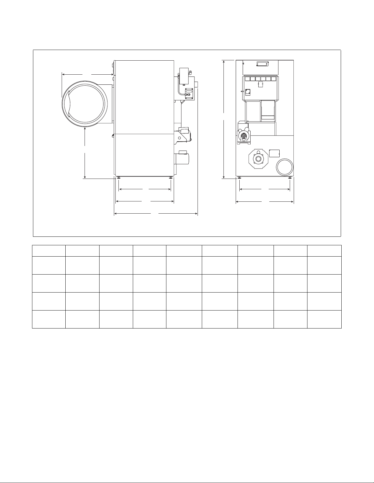
Installation
Specifications and Dimensions
Specifications 25 Pound 30 Pound T30 35 Pound T45 55 Pound
Noise level measured during
operation at operator position
of 1 meter (3.3 feet) in front of
machine and 1.6 meters (5.2
feet) from floor
Net Weight (approximate):
kg (pounds)
Cylinder Size:
mm (inches)
Cylinder Capacity (dry
weight):
kg (pounds)
Drive Motor Horsepower**
Fan Motor Horsepower**
Maximum Airflow
per Pocket**:
l/sec (C.F.M.)
Maximum Static
Back Pressure*:
mbar (inches W.C.)
50 Hertz
60 Hertz
50 Hertz
60 Hertz
60 dBA 61 dBA 66 dBA 63 dBA 67 dBA 63 dBA
137
(300)
673 x 610
(26.5 x 24)
11.3
(25)
1/41/41/41/41/21/2
1/41/41/41/41/21/2
203
(430)
236
(500)
1.5
(0.6)
2.0
(0.8)
150
(330)
673 x 762
(26.5 x 30)
13.6
(30)
203
(430)
236
(500)
1.5
(0.6)
2.0
(0.8)
247
(544)
762 x 660
(30 x 26)
2 x 13.6
(2 x 30)
160
(340)
189
(400)
2.0
(0.8)
2.3
(0.9)
Installation/Operation Supplement
163
(360)
762 x 762
(30 x 30)
15.9
(35)
260
(550)
307
(650)
1.3
(0.5)
1.5
(0.6)
305
(673)
838 x 762
(33 x 30)
2 x 20.5
(2 x 45)
N/A
283
(600)
N/A
2.3
(0.9)
197
(435)
838 x 889
(33 x 35)
24.9
(55)
283
(600)
330
(700)
1.3
(0.5)
1.5
(0.6)
Gas Connection
Gas Burner Rating**:
kW, Mj /h r (Btu /h r)
Heating Element
Rating**:
Steam Connection
Steam Coil Rating at 100
psig**:
Boiler Horsepower (Btu/hr)
Steam Coil Rating at 15 psig**:
Boiler Horsepower (Btu/hr)
* T30 and 45 models – both pockets running
** T30 and 45 models – each pocket
N/A = Not Applicable
400/50/3 10 kW
Standard 12 kW
1/2 in. NPT 1/2 in. NPT 1/2 in. NPT 1/2 in. NPT 1/2 in. NPT 1/2 in. NPT
18.7, 67.5
(64,000)
3/4 in. NPT 3/4 in. NPT 3/4 in. NPT 3/4 in. NPT
3.9
(134,700)
2.6
(89,940)
Gas Models
21.4, 77
(73,000)
Electric Models
21 kW 21 kW 24 kW N/A 27 kW
Steam Models
3.9
(134,700)
2.6
(89,940)
21.4, 77
(73,000)
3.2
(111,000)
2.2
(74,000)
26.4, 95
(90,000)
4.8
(166,000)
3.7
(129,000)
27.8, 100.2
(95,000)
N/A N/A
N/A N/A
N/A N/A
32.8, 118.2
(112,000)
70392201 (EN)
© Published by permission of the copyright owner – DO NOT COPY or TRANSMIT
7
Page 10
Installation/Operation Supplement
Cabinet Dimensions — 25, 30, 35 and 55 Pound Models
A
F
B
C
D
E
G
H
TMB2209N
Models A B C D E F G H
25 Pound
30 Pound
35 Pound
55 Pound
667 mm
(26.25 in.)
667 mm
(26.25 in.)
711 mm
(28 in.)
810 mm
(31.88 in.)
699 mm
(27.5 in.)
699 mm
(27.5 in.)
699 mm
(27.5 in.)
682.5 mm
(26.87 in.)
593 mm
(23.35 in.)
720 mm
(28.35 in.)
720 mm
(28.35 in.)
857.25 mm
(33.75 in.)
654 mm
(25.75 in.)
806 mm
(31.75 in.)
806 mm
(31.75 in.)
971.5 mm
(38.25 in.)
1038 mm
(40.875 in.)
1191 mm
(46.875 in.)
1191 mm
(46.875 in.)
1365 mm
(53.62 in.)
1622 mm
(63.875 in.)
1622 mm
(63.875 in.)
1622 mm
(63.875 in.)
1694.7 mm
(66.75 in.)
626 mm
(24.64 in.)
626 mm
(24.64 in.)
695 mm
(27.38 in.)
774.7 mm
(30.5 in.)
NOTE: Facia panels available to increase height of
single pocket models to 1835 mm (72.25 inches) and
1938 mm (76.25 inches).
TMB2209N
711 mm
(28 in.)
711 mm
(28 in.)
800 mm
(31.5 in.)
876 mm
(34.5 in.)
8
© Published by permission of the copyright owner – DO NOT COPY or TRANSMIT
70392201 (EN)
Page 11

Cabinet Dimensions – T30 and T45
Models
Installation/Operation Supplement
A
B
C
D
E
F
G I
H
J
TMB2230N
TMB2230N
ModelsABCDE
T30
711 mm
(28 in.)
1219 mm
(48 in.)
1118 mm
(44 in.)
279 mm
(11 in.)
254 mm
(10 in.)
T45
810 mm
(31.88 in.)
1245 mm
(49 in.)
N/A N/A
Models F G H I J
T30
T45
N/A = Not Applicable
636 mm
(25.02 in.)
746 mm
(29.37 in.)
1086 mm
(42.76 in.)
1235 mm
(48.62 in.)
695 mm
(27.38 in.)
775 mm
(30.50 in.)
800 mm
(31.5 in.)
876 mm
(34.5 in.)
NOTE: To meet ADA compliance, install a 102 mm
(4 inch) riser on T30 models only.
70392201 (EN)
© Published by permission of the copyright owner – DO NOT COPY or TRANSMIT
229 mm
(9 in.)
1937 mm
(76.25 in.)
2063.75 mm
(81.25 in.)
9
Page 12

Installation/Operation Supplement
Exhaust Outlet Locations
A
B
Models
25/30 Pound
T30
35 Pound
B
A
TMB2132N
25, 30, 35 AND 55 POUND T30 AND T45
TMB2132N TMB1969N
Rear Exhaust
Diameter A B C
152 mm
(6 in.)
Elliptical Fits
203 mm
(8 in.)
203 mm
(8 in.)
99 mm
(3.875 in.)
928 mm
(36.54 in.)
124 mm
(4.875 in.)
117 mm
(4.625 in.)
108 mm
(4.25 in.)
143 mm
(5.625 in.)
C
TMB1969N
N/A
1585 mm
(62.42 in.)
N/A
T45
55 Pound
N/A = Not Applicable
10
Elliptical Fits
254 mm
(10 in.)
203 mm
(8 in.)
© Published by permission of the copyright owner – DO NOT COPY or TRANSMIT
1038 mm
(40.88 in.)
122 mm
(4.808 in.)
121 mm
(4.75 in.)
156.3 mm
(6.156 in.)
1676 mm
(66 in.)
N/A
70392201 (EN)
Page 13

Gas Connection Locations
Installation/Operation Supplement
C
1
A
B
25, 30, 35 AND 55 POUND
TMB2106N
C
1
A
B
TMB1970N
T30 AND T45
1 1/2 in. NPT
Models
25 Pound
30 Pound
T30
35 Pound
T45
55 Pound
TMB2106N TMB1970N
Gas Connection
ABC
1500 mm
(59 in.)
1500 mm
(59 in.)
1912 mm
(75.28 in.)
1500 mm
(59 in.)
2000 mm
(78.75 in.)
1500 mm
(59 in.)
38.1 mm
(1.5 in.)
38.1 mm
(1.5 in.)
64 mm
(2.5 in.)
64 mm
(2.5 in.)
105 mm
(4.12 in.)
64 mm
(2.5 in.)
737 mm
(29 in.)
889 mm
(35 in.)
777 mm
(30.60 in.)
889 mm
(35 in.)
1089 mm
(42.88 in.)
889 mm
(35 in.)
70392201 (EN)
© Published by permission of the copyright owner – DO NOT COPY or TRANSMIT
11
Page 14

Installation/Operation Supplement
Electrical Connection Locations
B
A
25, 30, 35 AND 55 POUND
GAS AND STEAM
B
A
D
C
25, 30, 35 AND 55 POUND
ELECTRIC
D
TMB2204N
E
TMB2204N
Models
25/30
Pound
T30
35 Pound
T45
55 Pound
N/A = Not Applicable
12
C
T30 GAS AND STEAM
T45 GAS
T30 ELECTRIC
TMB1971N
TMB1971N
Electrical Service
Gas and Steam Models Electric Models
ABCDE
1581 mm
(62.25 in.)
1498 mm
(59 in.)
1581 mm
(62.25 in.)
1588 mm
(62.5 in.)
1655.75 mm
(65.187 in.)
© Published by permission of the copyright owner – DO NOT COPY or TRANSMIT
51 mm
(2 in.)
44 mm
(1.75 in.)
76 mm
(3 in.)
44 mm
(1.75 in.)
44.83 mm
(1.765 in.)
711 mm
(28 in.)
905 mm
(35.63 in.)
711 mm
(28 in.)
83 mm
(3.25 in.)
1859 mm
(73.21 in.)
108 mm
(4.25 in.)
N/A N/A N/A
826.16 mm
(32.526 in.)
166.3 mm
(6.547 in.)
N/A
58 mm
(2.28 in.)
N/A
N/A
70392201 (EN)
Page 15

Steam Connection Locations
Installation/Operation Supplement
C
Models
C
D
A
A
B
25, 30 AND 35 POUND
TMB2108N
TMB2108N TMB1972N
B
D
A
B
TMB1972N
T30
Inlet Outlet
ACBD
25/30/35 Pound
T30 (Upper)
T30 (Lower)
1365 mm
(53.75 in.)
1877 mm
(73.93 in.)
923 mm
(36.35 in.)
NOTE: All connections use 3/4 inch NPT pipe.
70392201 (EN)
© Published by permission of the copyright owner – DO NOT COPY or TRANSMIT
198 mm
(7.8 in.)
160 mm
(6.29 in.)
160 mm
(6.29 in.)
1080 mm
(42.5 in.)
1592 mm
(62.71 in.)
638 mm
(25.13 in.)
165 mm
(6.5 in.)
61 mm
(2.39 in.)
61 mm
(2.39 in.)
13
Page 16

Installation/Operation Supplement
Position and Level the Tumbler
WARNING
To reduce the risk of severe injury, clearance of tumbler cabinet from combustible
construction must conform to the minimum clearances.
W056
3
4
5
2
6
1
7
25, 30, 35 AND 55 POUND
TMB2021N
TMB2021N
3
1
4
2
5
6
7
T30 AND T45
TMB2110N
NOTE: Shaded areas indicate adjacent structure.
1 13 mm (0.5 in.) recommended between machines for removal or installations.
2 Allow 51-102 mm (2-4 in.) opening at top of machine to aid in removal or installation. A removable trim piece may
be used to conceal the opening; zero clearance allowed for trim.
3 102 mm (4 in.) Maximum Header Thickness
4 305 mm (12 in.) Minimum Clearance
5 610 mm (24 in.) minimum, 914 mm (36 in.) recommended for maintenance purposes.
6 Provision for make-up air: Minimum 709 cm
35 and 55 pound models, 1418 cm
2
(220 in.
2
(110 in.
2
) for T30 models and 1856 cm
2
) required per tumbler for 25 and 30, 928 cm2 (144 in.2) for
2
(288 in.
2
) for T45 models. Location
for reference only. May be anywhere behind tumbler.
6 mm (0.25 in.) recommended for removal or installation purposes, zero clearance allowed.
Figure 1
14
© Published by permission of the copyright owner – DO NOT COPY or TRANSMIT
TMB2110N
70392201 (EN)
Page 17

Installation/Operation Supplement
Gas Requirements
Natural Gas and Liquefied Petroleum
WARNING
To reduce the risk of fire or explosion, DO
NOT CONNECT THE GAS LINE TO THE
TUMBLER IF THE GAS SERVICE IS NOT
THE SAME AS THAT SPECIFIED ON THE
TUMBLER SERIAL PLATE! It will first be
necessary to convert the gas burner
orifice and gas valve. Appropriate
conversion kits are available.
IMPORTANT: Any product revisions or
conversions must be made by the Manufacturer’s
Authorized Dealers, Distributors, or local service
personnel.
IMPORTANT: The tumbler must be isolated
the gas supply piping system by closing its
individual manual shut-off valve during any
pressure testing of the gas supply piping system at
test pressure equal to or less than
3.45 kPa,
34.5 mbar (0.5 psi).
IMPORTANT: The tumbler and its manually
operated appliance gas valve must be disconnected
from the gas supply piping system during any
pressure testing of that system at test pressures in
excess of
3.45 kPa, 34.5 mbar (0.5 psi).
IMPORTANT: The installation must comply with
local codes.
W060
from
European Gas
WARNING
To reduce the risk of electric shock, fire,
explosion, serious injury or death:
• Disconnect electric power to the
tumbler before servicing.
• Close gas shut-off valve to gas tumbler
before servicing.
• Close steam valve to steam tumbler
before servicing.
• Never start the tumbler with any guards/
panels removed.
• Whenever ground wires are removed
during servicing, these ground wires
must be reconnected to ensure that the
tumbler is properly grounded.
General Information
This information is to be used when installing gas
tumblers in countries, and/or on gases, different than
the machine’s factory configuration. Tumblers are
supplied from the factory for operation on Natural Gas
or L.P. Gas in the countries of GB/IE/PT/ES/IT/GR/
LU/CH. To install machines in any other country, or
on any other gas, requires some level of modification.
Models are built in two different configurations:
● Regulated Natural Gas – Burner orifice is sized
for Natural Gas, second family, group H (E) at
20 mbar inlet pressure. Regulator/governor is
operational. Gas valve CAN be field-converted to
a non-regulating type.
W002
WARNING
To reduce the risk of fire or explosion, if
the tumbler is to be connected to
Liquefied Petroleum (L.P.) gas, a vent to
the outdoors must be provided in the
room where the tumbler is installed.
NOTE: This manual is only a supplement. Refer to
installation/operation manual for full instructions.
70392201 (EN)
© Published by permission of the copyright owner – DO NOT COPY or TRANSMIT
W062
● Unregulated Liquefied Petroleum (L.P.) Gas –
Burner orifice is sized for L.P., third family,
group 3+ at 28.37 mbar inlet pressure. Regulator/
governor is blocked open. Gas valve CANNOT
be field-converted to a regulating type.
Serial plates supplied from the factory are configured
for the countries of GB/IE/PT/ES/IT/GR/LU/CH.
These instructions pertain to the situations when the
country of use or gas supply is different than that on
the serial plate.
NOTE: This manual is only a supplement. Refer to
installation/operation manual for full instructions.
15
Page 18

Installation/Operation Supplement
Gases and Configurations
Country
Code
DK/NO/
SE/FI/CZ/
EE/LV/LT/
SI/SK
DE
Burner
Orifice
Pressure,
mbar
Capacity/
Gas Type Group
Supply
Pressure,
mbar
Natural Gas H 20 7.6
8.0
8.0
8.0
8.0
8.0
L.P. Gas B/P 30 No Governor 25
Natural Gas E 20 7.6
8.0
8.0
8.0
8.0
8.0
L.P. Gas LL 30 No Governor 25
Model
25
30
T30
35
T45
55
30
T30
35
T45
55
25
30
T30
35
T45
55
30
T30
35
T45
55
Diameter,
mm
3.9
4.0
4.0
4.6
4.6
5.2
2.1
2.2
2.2
2.5
2.5
3.0
3.9
4.0
4.0
4.6
4.6
5.2
2.1
2.2
2.2
2.5
2.5
3.0
Quantity
1
1
2
1
2
1
1
1
2
1
2
1
1
1
2
1
2
1
1
1
2
1
2
1
Burner
Orifice
Part No.
M402980
M402992
M402992
M411511
M411371
M402993
M401003
M401011
M401011
M406361
M401007
M401017
M402980
M402992
M402992
M411511
M411371
M402993
M401003
M401011
M401011
M406361
M401007
M401017
Natural Gas L 25 11.0 25
NL
L.P. Gas B/P 30 No Governor 25
Table 1 (continued)
Burner orifice information at 0-600 meters (0-2000 feet) altitude.
30
T30
35
T45
55
30
T30
35
T45
55
3.9
4.0
4.0
4.6
4.6
4.8
2.1
2.2
2.2
2.5
2.5
3.0
1
1
2
1
2
1
1
1
2
1
2
1
M402980
M402992
M402992
M411511
M411371
M411372
M401003
M401011
M401011
M406361
M401007
M401017
16
© Published by permission of the copyright owner – DO NOT COPY or TRANSMIT
70392201 (EN)
Page 19

Table 1 (continued)
Installation/Operation Supplement
Country
Code
BE/FR*
GB/IE/PT/
ES/IT/GR/
LU/CH
Burner
Orifice
Pressure,
mbar
Capacity/
Model
Gas Type Group
Supply
Pressure,
mbar
Natural Gas E+ 20 or 25 No Governor 25
30
T30
35
T45
55
L.P. Gas + 28 or 37 No Governor 25
30
T30
35
T45
55
Natural Gas H 20 7.6
8.0
8.0
8.0
8.0
8.0
25
30
T30
35
T45
55
L.P. Gas + 28 or 37 No Governor 25
30
T30
35
T45
55
Diameter,
mm
3.9
3.3
3.3
3.7
3.7
4.0
2.1
2.2
2.2
2.5
2.5
2.8
3.9
4.0
4.0
4.6
4.6
5.2
2.1
2.2
2.2
2.5
2.5
2.8
Quantity
1
1
2
1
2
1
1
1
2
1
2
1
1
1
2
1
2
1
1
1
2
1
2
1
Burner
Orifice
Part No.
M402980
M401021
M401021
M400998
M401000
M401012
M401003
M401011
M401011
M406361
M401007
M411512
M402980
M402992
M402992
M411511
M411371
M402993
M401003
M401011
M401011
M406361
M401007
M411512
Natural Gas H 20 7.6
AT
L.P. Gas B/P 30 No Governor 25
L.P. Gas B/P 30 No Governor 25
CY/IS/MT
Table 1 (continued)
Burner orifice information at 0-600 meters (0-2000 feet) altitude.
*For Natural Gas, Group E+ applications, convert using L.P. Gas
model and replace burner orifice.
8.0
8.0
8.0
8.0
8.0
25
30
T30
35
T45
55
30
T30
35
T45
55
30
T30
35
T45
55
3.9
4.0
4.0
4.6
4.6
5.2
2.1
2.2
2.2
2.5
2.5
3.0
2.1
2.2
2.2
2.5
2.5
3.0
1
1
2
1
2
1
1
1
2
1
2
1
1
1
2
1
2
1
M402980
M402992
M402992
M411511
M411371
M402993
M401003
M401011
M401011
M406361
M401007
M401017
M401003
M401011
M401011
M406361
M401007
M401017
70392201 (EN)
© Published by permission of the copyright owner – DO NOT COPY or TRANSMIT
17
Page 20

Installation/Operation Supplement
Table 1 (continued)
Country
Code
HU
PL
Burner
Orifice
Pressure,
mbar
Capacity/
Gas Type Group
Supply
Pressure,
mbar
Natural Gas H 25 7.6
8.0
8.0
8.0
8.0
8.0
L.P. Gas B/P 30 No Governor 25
Natural Gas H 20 7.6
8.0
8.0
8.0
8.0
8.0
L.P. Gas 3P 37 No Governor 25
Model
25
30
T30
35
T45
55
30
T30
35
T45
55
25
30
T30
35
T45
55
30
T30
35
T45
55
Diameter,
mm
3.9
4.0
4.0
4.6
4.6
5.2
2.1
2.2
2.2
2.5
2.5
3.0
3.9
4.0
4.0
4.6
4.6
5.2
2.1
2.2
2.2
2.5
2.5
2.8
Quantity
1
1
2
1
2
1
1
1
2
1
2
1
1
1
2
1
2
1
1
1
2
1
2
1
Burner
Orifice
Part No.
M402980
M402992
M402992
M411511
M411371
M402993
M401003
M401011
M401011
M406361
M401007
M401017
M402980
M402992
M402992
M411511
M411371
M402993
M401003
M401011
M401011
M406361
M401007
M411512
Burner orifice information at 0-600 meters (0-2000 feet) altitude.
Tab le 1
18
© Published by permission of the copyright owner – DO NOT COPY or TRANSMIT
70392201 (EN)
Page 21

Installation/Operation Supplement
Exhaust Requirements
WARNING
A drying tumbler produces combustible
lint. To reduce the risk of fire, the tumbler
must be exhausted to the outdoors.
T o reduce the risk of fire and accum ulation
of combustible gases, DO NOT exhaust
tumbler air into a window well, gas vent,
chimney or enclosed, unventilated area
such as an attic wall, ceiling, crawl space
under a building, or concealed space of a
building.
Make-Up Air
IMPORTANT: Do not obstruct the flow of
combustion and ventilation air.
A tumbler is forced air exhausted and requires
provisions for make-up air to replace the air exhausted
by the tumbler.
The required make-up air opening to the outside for
tumbler is:
each
W057
W059
Venting
Proper sized exhaust ducts are essential for proper
operation. All elbows should be sweep type. Exhaust
ducts must be assembled so the interior surfaces are
smooth to prevent the accumulation of lint.
DO NOT use plastic or thin foil flexible ducts. Use
exhaust ducts made of sheet metal or other
noncombustible material. Use duct tape or pop-rivets
on all seams and joints.
Verify that old ducts are thoroughly cleaned out before
installing new tumbler.
NOTE: The ducts must be equivalent in strength
and corrosion resistance to ducts made of
galvanized sheet steel not less than 0.495 mm
(0.0195 inches) thick.
IMPORTANT: For best performance, provide an
individual exhaust duct for each tumbler. Do not
install a hot water heater in room containing
tumblers. It is better to have the water heater in a
separate room with a separate air inlet.
NOTE: This manual is only a supplement. Refer to
installation/operation manual for full instructions.
709 sq. cm (110 sq. in.) for 25 and 30 pound models
928 sq. cm (144 sq. in.) for 35 and 55 pound models
1418 sq. cm (220 sq. in.) for T30 models
1856 sq. cm (288 sq. in.) for T45 models
Make-up air openings with louvers will restrict
airflow. The opening must be increased to compensate
for area taken up by louvers.
If it is necessary to duct make-up air to the tumbler(s),
increase the area of the ductwork by 25% to
compensate for any restriction in air movement.
70392201 (EN)
© Published by permission of the copyright owner – DO NOT COPY or TRANSMIT
19
Page 22

Installation/Operation Supplement
Electrical Requirements
WARNING
To reduce the risk of electric shock, fire,
explosion, serious injury or death:
• Disconnect electric power to the tumbler
before servicing.
• Close gas shut-off valve to gas tumbler
before servicing.
• Close steam valve to steam tumbler
before servicing.
• Never start the tumbler with any guards/
panels removed.
• Whenever ground wires are removed
during servicing, these ground wires
must be reconnected to ensure that the
tumbler is properly grounded.
To reduce the risk of fire and electric
shock, check with a qualified serviceman
for proper gr ounding procedures. Improper
connection of the equipment grounding
conductor may result in a risk of electric
shock.
To reduce the risk of fire and electric
shock, if electrical supply is coming fr om a
three phase service, DO NOT connect a
“High Leg” or “Stinger Leg” to a single
phase machine. On a three phase machine,
if there is a “High Leg” or “Stinger Leg” it
should be connected to L3.
Grounding Instructions
W002
W068
W069
● Metal conduit and/or BX cable is not considered
ground.
● Connecting the Neutral from the electrical
service box to the tumbler ground screw does not
constitute a ground.
● A dedicated ground conduit (wire) must be
connected between the electrical service box
ground bar and the tumbler ground screw.
WARNING
To reduce the risk of electrical shock,
de-energize the electrical circuit being
connected to the tumbler before making
any electrical connections. All electrical
connections should be made by a qualified
electrician. Never attempt to connect a live
circuit.
W409
CAUTION
Label all wires prior to disconnection when
servicing controls. Wiring err ors can cause
improper and dangerous operation. Verify
proper operation after servicing.
W071
All manually operated models are factory-equipped
with an emergency stop button on the front panel.
NOTE: Activation of the emergency stop button
stops all machine control circuit functions, but
DOES NOT remove all electrical power from
machine.
NOTE: To ensure protection against shock, this
tumbler MUST be electrically grounded in
accordance with the local codes or, in the absence of
local codes, with the latest edition of the National
Electrical Code ANSI/NFPA No. 70.
In the event of malfunction or breakdown, grounding
will reduce the risk of electric shock by providing a
path of least resistance for electric current. This
tumbler must be connected to a grounded metal,
permanent wiring system; or an equipment grounding
conductor must be run with the circuit conductors and
connected to the appropriate ground location.
20
© Published by permission of the copyright owner – DO NOT COPY or TRANSMIT
NOTE: This manual is only a supplement. Refer to
installation/operation manual for full instructions.
70392201 (EN)
Page 23

Steam Requirements
NOTE: The maximum allowable steam pressure is
8.6 bar (125 psig). In no case may the pressure
exceed this value.
Obtain specific steam service pipe sizes from the
steam system supplier or a qualified steam fitter.
● Refer to Fig ure 2 for proper steam pipe
configurations.
● When tumbler is on the end of a line of
equipment, extend header at least 1.2 meters
(4 feet) beyond tumbler. Install shut-off valve,
union, check valve and bypass trap at end of line.
If system has a gravity return to the boiler, omit
trap.
● Insulate steam supply and return lines for safety
of operator and safety while servicing tumbler.
● Keep tumbler in good working condition. Repair
or replace any worn or defective parts.
Installation/Operation Supplement
WARNING
All system components must have a
8.6 bar (125 psig) working pressure.
Shut-off valves must be installed upstream
of the steam solenoid valve and
downstream of each steam trap so
components can be isolated for
maintenance or emergency purposes.
All components (solenoid valve, traps)
must be supported to minimize loads on
the tumbler steam coil connections.
W701
NOTE: This manual is only a supplement. Refer to
installation/operation manual for full instructions.
70392201 (EN)
© Published by permission of the copyright owner – DO NOT COPY or TRANSMIT
21
Page 24

Installation/Operation Supplement
2
1
4
10
9
5
6
8
SUPPLY
3
4
RETURN
7
6
5
10
Note: Refer to Tabl e 2 for sizing of steam lines. Piping must also be sized accordingly for length of runs, and number
of elbows.
1 Steam Coil 6 Trap with Built-In Strainer
2 305 mm (12 in.) Riser 7 Vacuum Breaker (Optional)
3 Condensate Return Line from Supply Line 8 457 mm (18 in.) Drop
4 Shut-Off Valve 9 Solenoid Valve (Supplied with machine)
5 Check Valve 10 Union
T473I
T473I
Figure 2
Model
25/30 Pound
T30
35 Pound
* Based on 100 PSI.
Steam Pressure
PSI (bar)
Minimum Pipe Diameter
15-100 (1-6.9) 3/4 in. NPT 134
15-100 (1-6.9) 3/4 in. NPT 110
15-100 (1-6.9) 3/4 in. NPT 166
Steam Trap Size *
(Pounds Condensate/Hour)
Table 2
22
© Published by permission of the copyright owner – DO NOT COPY or TRANSMIT
70392201 (EN)
Page 25

Installation/Operation Supplement
Operation
WARNING
To reduce the risk of fire:
• DO NOT DRY articles containing foam rubber or similarly textured rubberlike materials.
• DO NOT DRY plastics, anything containing wax or chemicals such as mops and cleaning
cloths, or anything dry-cleaned at home with a dry-cleaning solvent.
• DO NOT TUMBLE fiberglass curtains and draperies unless the label says it can be done. If
they are dried, wipe out the cylinder with a damp cloth to remove particles of fiberglass.
To reduce the risk of serious injury, allow cylinder to stop before cleaning lint screen.
W076
W412
Emergency Stop Button
All OPL tumblers are factory equipped with an
emergency stop button located on the front panel.
Refer to Figure 3.
1
TMB1664N
1 Emergency Stop Button
Figure 3
To operate emergency stop button:
a. Press red emergency stop button to stop all
action.
b. To restart machine, pull red emergency stop
button out and press START pad or button.
IMPORTANT: Clean lint screen and lint
compartment daily. Failure to clean the lint screen
daily will result in higher than normal
temperatures that may damage laundry.
Step 2: Load Laundry
Open loading door and load cylinder with laundry. DO
NOT OVERLOAD.
NOTE: Overloading causes slow drying and
wrinkling.
Close loading door. Tumbler will not operate with the
door open.
Step 3: Determine Control Type and
Temperature Setting
Refer to the various controls in the Control
Instructions Section, pages 24 - 27 determine
appropriate control and then follow the instructions.
T30 Models Only: Use the correct coin slot and
control panel for the top or bottom cylinder.
The type of fabric being dried will determine the
temperature setting. Consult the fabric care label or
fabric manufacturer to determine proper temperature
setting.
NOTE: Activation of the emergency stop button
stops all machine control circuit functions but
DOES NOT remove all electrical power from
machine.
Operating Instructions
Step 1: Clean Lint Screen/Compartment
Remove any accumulated lint from the lint screen and
compartment. Close panel tightly against tumbler
frame and lock panel securely, if applicable.
70392201 (EN)
© Published by permission of the copyright owner – DO NOT COPY or TRANSMIT
IMPORTANT: Always follow the fabric care
instructions supplied by the garment
manufacturer.
Step 4: Remove Laundry
When the cycle is complete, open door and remove the
laundry.
23
Page 26

Installation/Operation Supplement
Control Instructions
Dual Digital Timer Control
QT Control Suffix
1. Select HIGH, MED, LOW or NO HEAT by
turning the temperature knob.
TMB2147N
Figure 4
2. Set the HEAT TIME for the number of minutes
(from 0-60) desired.
4. Press and release START button to start tumbler.
Display will show minutes remaining before end
of cycle.
TMB2150N
Figure 7
IMPORTANT: To stop the tumbler at any time
during the cycle, OPEN DOOR. If the loading door
or lint panel door is opened during the cycle, the
heating system will shut off and the motor will stop.
To restart the cycle, both doors must be closed and
the START button must be pressed in.
5. When the cycle is complete, open door and
remove the laundry.
TMB2148N
Figure 5
3. Set the COOL DOWN TIME for the number of
minutes (from 0-15) desired.
TMB2149N
Figure 6
24
© Published by permission of the copyright owner – DO NOT COPY or TRANSMIT
70392201 (EN)
Page 27

Installation/Operation Supplement
Electronic OPL Micro Control
H, L, P, S, U and Y Models with
OM Control Suffix
1. To use an Automatic Cycle, press an ON/
SELECT pad. Select HIGH, MEDIUM,
MED LOW, LOW or NO HEAT for items that
should not be dried with heat. A light to the left
of the selected pad lights up.
To use a Time Dry or Custom Cycle, refer to the
Programming Manual.
ON / SELECT
HIGH
MEDIUM
MED LOW
LOW
NO HEAT
NOTE: All pads can be pressed in any sequence
without damaging control or tumbler. To stop the
tumbler at any time, open the door or press STOP/
RESET.
STOP/RESET
TMB1484N
Figure 11
NOTE: The window display will flash. Press STOP/
RESET twice (within 3 seconds) to end the cycle
and reset the control to idle status. To restart the
tumbler, CLOSE door and press START pad.
IMPORTANT: If the loading door or lint panel
door is opened during the cycle, the heating system
will shut off and the motor will stop. To restart the
cycle, both doors must be closed and the PUSH TO
START button must be pressed in.
3. When the cycle is complete, open door and
remove the laundry.
TMB1483N
Figure 8
NOTE: Do not press directly on lights or the center
of pad. For proper selection, press on pad slightly
to the right of center. Refer to Figure 9.
TMB806N
Figure 9
2. Press START pad to start tumbler.
START
TMB1485N
Figure 10
G and K Models with OM Control Suffix
1. To use an Automatic Cycle, press a
TEMPERATURE pad. Select HIGH, MED,
LOW, DELICATE or NO HEAT for items that
should not be dried with heat. A light to the left
of the selected pad lights up.
To use a Time Dry or Custom Cycle, refer to the
Programming Manual.
TMB2201N
Figure 12
70392201 (EN)
© Published by permission of the copyright owner – DO NOT COPY or TRANSMIT
25
Page 28

Installation/Operation Supplement
2. Press START pad to start tumbler.
TMB2202N
Figure 13
NOTE: All pads can be pressed in any sequence
without damaging control or tumbler. To stop the
tumbler at any time, open the door or press STOP.
TMB2203N
Figure 14
NOTE: The window display will flash. Press STOP
twice (within 3 seconds) to end the cycle and reset
the control to idle status. To restart the tumbler,
CLOSE door and press START pad.
Single Drop Control
SD and SX Control Suffixes
1. Select HIGH, MED, LOW or NO HEAT by
turning the temperature knob.
Figure 15
2. Insert the coin(s) in the coin slot.
C
25
TMB2147N
IMPORTANT: If the loading door or lint panel
door is opened during the cycle, the heating system
will shut off and the motor will stop. To restart the
cycle, both doors must be closed and the PUSH TO
START button must be pressed in.
3. When the cycle is complete, open door and
remove the laundry.
TMB1492N
Figure 16
3. Press START button to start tumbler
TMB2150N
Figure 17
IMPORTANT: To stop the tumbler at any time
during the cycle, OPEN DOOR. To restart the
tumbler, CLOSE door and press START button.
4. When the cycle is complete, open door and
remove the laundry.
26
© Published by permission of the copyright owner – DO NOT COPY or TRANSMIT
70392201 (EN)
Page 29

Installation/Operation Supplement
B
MDC Coin and Card Control
BC, BG, BL, BX and BY Control Suffixes
1. Select temperature by pressing the appropriate
temperature pad.
TMB1962N
Figure 18
2. Insert the coin(s) in the coin slot, or the card into
the opening.
C
25
3. Press START pad to start tumbler.
START
TMB1491N
Figure 20
IMPORTANT: To stop the tumbler at any time
during the cycle, OPEN DOOR. To restart the
tumbler, CLOSE door and press START pad.
4. When the cycle is complete, open door and
remove the laundry.
TMB1492N TMB1963N
Figure 19
TM
70392201 (EN)
© Published by permission of the copyright owner – DO NOT COPY or TRANSMIT
27
Page 30

Installation/Operation Supplement
Ignition Control Operation
Flame Probe Tests
Unexpected Presence of Flame
The Unexpected Presence of Flame test is performed
when no flame is expected. Failure of this test results
in the ignition control entering Lockout Mode with the
Diagnostic LED displaying Error Code 3.
Flame Monitoring
During the Flame Monitoring test, the flame is
checked to ensure the gas is being burned when the gas
valve is on. Failure of this test will result in the
ignition control entering Lockout Mode with the
Diagnostic LED displaying Error Code 3.
Error
Code
1
2
3
4
5
6
Red Ignition Control Internal Failure
2 Red Flashes Gas Valve Not Connected
3 Red Flashes Ignition/Flame Sense Failure
4 Red Flashes Reset Switch is Shorted
Slow Red and Green Flashes Low Voltage Detection
Fast Red and Orange Flashes Ignition Control is in Reset Delay
DGN LED status Fault Type
Diagnostic LED (DGN LED) / Error Codes
The Diagnostic LED or DGN LED is located by the
power connector on the ignition control. Refer to
Figure 21. The Diagnostic LED will indicate the status
of the ignition control. Refer to Table 3.
LED Color Description
Orange-Yellow Initialization
Green Standby / Normal Operation
Red Fault Indication Code
Table 3
The Diagnostic LED will flash error codes one half
second on and one half second off. Error codes are
separated by a one second pause before the code is
repeated.
1 Diagnostic (DGN) LED
Figure 21
1
TMB2176N
28
© Published by permission of the copyright owner – DO NOT COPY or TRANSMIT
70392201 (EN)
Page 31

Disposal of Unit
This appliance is marked according to the European
directive 2002/96/EC on Waste Electrical and
Electronic Equipment (WEEE).
This symbol on the product or on its packaging
indicates that this product shall not be treated as
household waste. Refer to Figure 22. Instead it shall be
handed over to the applicable collection point for the
recycling of electrical and electronic equipment.
Ensuring this product is disposed of correctly will help
prevent potential negative consequences for the
environment and human health which could otherwise
be caused by inappropriate waste handling of this
product. The recycling of materials will help to
conserve natural resources. For more detailed
information about recycling of this product, please
contact the local city office, household waste disposal
service, or the source from which the product was
purchased.
Installation/Operation Supplement
MIX1N
Figure 22
70392201 (EN)
© Published by permission of the copyright owner – DO NOT COPY or TRANSMIT
29
 Loading...