

Alliance Laundry Systems DT0220SFG, DA0220SRG, JT0300DRG, DC0220SRG, DT0220SRG Installation Manual
...Page 1
Drying Tumblers
Stacked 30 Pound (300 Liter) Capacity
Refer to Page 5 for Model Identification
NOTA: El manual en
español aparece después
del manual en inglés.
25 Pound (220 Liter) Capacity
30 Pound (270 Liter) Capacity
35 Pound (350 Liter) Capacity
H
I
G
H
T
E
M
P
S
T
A
R
T
L
O
W
T
E
M
P
M
E
D
T
E
M
P
N
O
H
E
A
T
C
25
1
S
E
L
E
C
T
T
E
M
P
1
S
E
L
2
E
C
T
T
I
E
N
M
S
E
P
3
R
T
C
O
P
I
H
U
N
I
S
G
H
H
S
T
T
E
A
M
R
P
T
S
T
A
R
T
L
O
W
T
E
M
P
M
E
2
I
N
S
E
3
R
T
C
O
P
I
U
N
S
H
S
T
A
R
T
D
T
E
M
P
N
O
H
E
A
T
C
25
Installation
Keep These Instructions for Future Reference.
(If this machine changes ownership, this manual must accompany machine.)
T477C
T477C T478C
www.comlaundry.com
T478C
Part No. 70223701R2
June 2002
Page 2

Page 3
Installation must conform with local codes or, in the absence of local codes, with:
FOR YOUR SAFETY, the information in
this manual must be followed to minimize
the risk of fire or explosion or to prevent
property damage, personal injury or
death.
W033
• Do not store or use gasoline or other
flammable vapors and liquids in the
vicinity of this or any other appliance.
• WHAT TO DO IF YOU SMELL GAS:
– Do not try to light any appliance.
– Do not touch any electrical switch; do
not use any phone in your building.
– Clear the room, building or area of all
occupants.
– Immediately call your gas supplier
from a neighbor’s phone. Follow the
gas supplier’s instructions.
– If you cannot reach your gas supplier,
call the fire department.
• Installation and service must be
performed by a qualified installer,
service agency or the gas supplier.
W052
WARNING
FOR YOUR SAFETY
Do not store or use gasoline or other
flammable vapors and liquids in the
vicinity of this or any other appliance.
W053
In the U.S.A.
, installation must conform to the latest edition of the American National Standard Z223.1/
NFPA 54 “National Fuel Gas Code” and Standard ANSI/NFPA 70 “National Electric Code.”
In Canada
, installation must comply with Standards CSA-B149.1 or Natural Gas and Propane Installation
Code and CSA C22.1, latest edition, Canadian Electric Code, Part I.
In Australia
, installation must comply with the Australian Gas Association Installation Code for Gas
Burning Appliances and Equipment.
IMPORTANT: Information must be obtained from a local gas supplier on instructions to be followed if the
user smells gas. These instructions must be posted in a prominent location. Step-by-step instructions of the
above safety information must be posted in a prominent location near the tumbler for customer use.
AVERTISSEMENT
POUR VOTRE SÉCURITÉ il est impératif
de suivre les instructions de ce manuel
pour minimiser les risques d’incendie ou
d’explosion et pour éviter les dommages
matériels, les blessures corporelles ou la
mort.
W033Q
• Ne pas entreposer ni utiliser d’essence
ni d’autres vapeurs ou liquides
inflammables dans le voisinage de cet
appareil ou de tout autre appareil.
• QUE FAIRE SI VOUS SENTEZ UNE
ODEUR DE GAZ :
– Ne pas tenter d’allumer d’apareil.
– Ne touchez à aucun interrupteur. Ne
pas vous servir des téléphones se
trouvant dans le bâtiment où vous
vous trouvez.
–Évacuez la pièce, le bâtiment ou la
zone.
– Appelez immédiatement votre
fournisseur de gaz depuis un voisin.
Suivez les instructions du
fournisseur.
– Si vous ne pouvez rejoindre le
fournisseur de gaz, appelez le service
des incendies.
• L’installation et l’entretien doivent être
assurés par un installateur ou un
service d’entretien qualifié ou par le
fournisseur de gaz.
W052Q
POUR VOTRE SÉCURITÉ
Ne pas entreposer ni utiliser d’essence ni
d’autres vapeurs ou liquides
inflammables dans le voisinage de cet
appareil ou de tout autre appareil.
W053Q
70223701
© Copyright, Alliance Laundry Systems LLC – DO NOT COPY or TRANSMIT
1
Page 4

Notes
2
© Copyright, Alliance Laundry Systems LLC – DO NOT COPY or TRANSMIT
70223701
Page 5

Table of
Contents
Introduction......................................................................................... 5
Model Identification ............................................................................. 5
Customer Service.................................................................................. 6
Wiring Diagram.................................................................................... 6
Serial Plate Location............................................................................. 7
Safety Information .............................................................................. 9
Important Safety Instructions ............................................................... 10
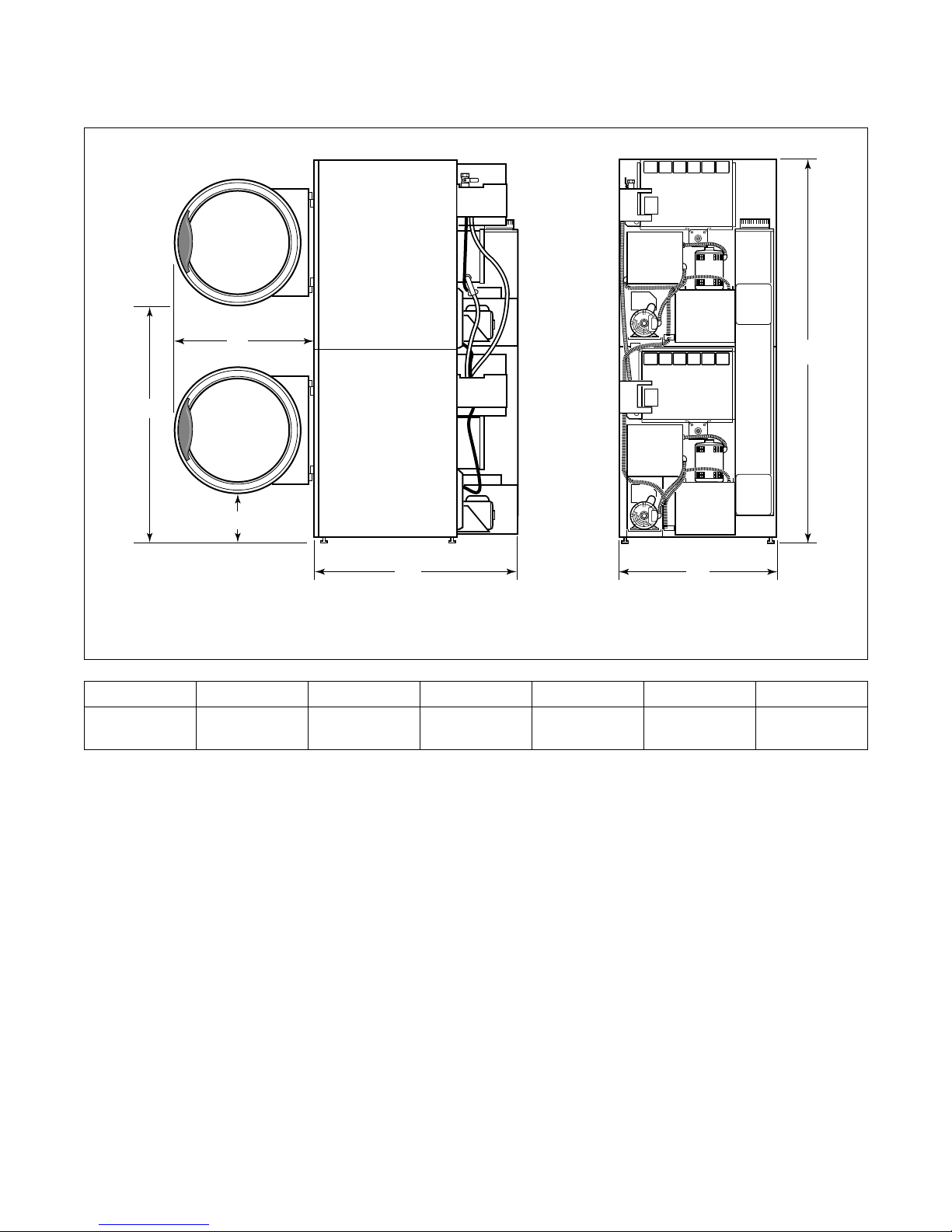
Specifications and Dimensions........................................................... 13
Cabinet Dimensions.............................................................................. 14
Cabinet Dimensions – Stacked Model.................................................. 15
Exhaust Outlet Locations...................................................................... 16
Gas Connection Locations.................................................................... 17
Electrical Connection Locations........................................................... 18
Steam Connection Locations................................................................ 19
Installation........................................................................................... 21
Pre-Installation Inspection.................................................................... 21
Location Requirements......................................................................... 21
Tumbler Enclosure................................................................................ 22
Position and Level the Tumbler............................................................ 23
Installing Accessory Timing Cam ........................................................ 24
Removal of Existing Timing Cam................................................... 24
Installation of New Timing Cam ..................................................... 24
Before Placing Tumbler into Service ................................................... 25
Required for CE Marked (European) Models Only......................... 26
Installing Gas Drying Tumblers in the European Union...................... 27
General Information......................................................................... 27
Basic Configuration ......................................................................... 28
Specific Conversion Procedures...................................................... 29
Exhaust Requirements ....................................................................... 37
Layout................................................................................................... 37
Make-Up Air......................................................................................... 37
Venting ................................................................................................. 37
Individual Venting ........................................................................... 38
Manifold Venting............................................................................. 39
Gas Requirements............................................................................... 43
Gas Supply Pipe Sizing and Looping ................................................... 45
High Altitude Orifice Sizing................................................................. 47
© Copyright 2002, Alliance Laundry Systems LLC
All rights reserved. No part of the contents of this book may be reproduced or transmitted in any form or by any
means without the expressed written consent of the publisher.
70223701
© Copyright, Alliance Laundry Systems LLC – DO NOT COPY or TRANSMIT
3
Page 6

Electrical Requirements..................................................................... 49
Grounding Instructions......................................................................... 49
Service/Ground Location...................................................................... 50
Connecting Electrical Service............................................................... 51
Configuring Your Tumbler for Other Service Voltages.................. 51
Stacked Tumbler Electrical Connections......................................... 52
For CE Marked Models Only .......................................................... 52
Conversion Instructions........................................................................ 53
Ferrite Ring Installation........................................................................ 56
Electrical Requirements for Gas and Steam Models............................ 57
Electrical Requirements for Electric Models........................................ 59
Steam Requirements........................................................................... 63
Piping Recommendations..................................................................... 63
Adjustments......................................................................................... 65
Loading Door Switch............................................................................ 65
Airflow Switch...................................................................................... 66
Door Strike............................................................................................ 66
Removing Tumbler from Service...................................................... 67
4
© Copyright, Alliance Laundry Systems LLC – DO NOT COPY or TRANSMIT
70223701
Page 7

Introduction
Model Identification
Information in this manual is applicable to these models. †
Gas Steam Electric
25 Pound
(220 Liter)
30 Pound
(270 Liter)
30 Pound
Stacked
(300 Liter)
35 Pound
(350 Liter)
DA0220SRG
DC0220SFG
DC0220SRG
DT0220SFG
DT0220SRG
GC0220SRG
GT0220SRG
JA0220SRG
JC0220SFG
DA0270SRG
DC0270SFG
DC0270SRG
DT0270SFG
DT0270SRG
GC0270SFG
GC0270SRG
GT0270SFG
GT0270SRG
JA0270SRG
DC0300DFG
DC0300DRG
DT0300DFG
DT0300DRG
JA0300DRG
JC0300DFG
JC0300DRG
JT0300DFG
AT0350SRG
DA0350SRG
DC0350SFG
DC0350SRG
DT0350SFG
DT0350SRG
JA0350SRG
JC0350SFG
JC0220SRG
JT0220SFG
JT0220SRG
SA0220SRG
SC0220SFG
SC0220SRG
ST0220SFG
ST0220SRG
JC0270SFG
JC0270SRG
JT0270SFG
JT0270SRG
SA0270SRG
SC0270SFG
SC0270SRG
ST0270SFG
ST0270SRG
JT0300DRG
NT0300DRG
SA0300DRG
SC0300DFG
SC0300DRG
ST0300DFG
ST0300DRG
JC0350SRG
JT0350SFG
JT0350SRG
SA0350SRG
SC0350SFG
SC0350SRG
ST0350SFG
ST0350SRG
DC0220SSH
DC0220SSL
DT0220SSH
DT0220SSL
GC0220SSL
GT0220SSL
JC0220SSH
DC0270SSH
DC0270SSL
DT0270SSH
DT0270SSL
GC0270SSH
GC0270SSL
GT0270SSH
GT0270SSL
DC0300DSH
DC0300DSL
DT0300DSH
DT0300DSL
JC0300DSH
JC0300DSL
AT0350SSH
AT0350SSL
DC0350SSH
DC0350SSL
DT0350SSH
DT0350SSL
JC0350SSH
JC0220SSL
JT0220SSH
JT0220SSL
SC0220SSH
SC0220SSL
ST0220SSH
ST0220SSL
JC0270SSH
JC0270SSL
JT0270SSH
JT0270SSL
SC0270SSH
SC0270SSL
ST0270SSH
ST0270SSL
JT0300DSH
JT0300DSL
SC0300DSH
SC0300DSL
ST0300DSH
ST0300DSL
JC0350SSL
JT0350SSH
JT0350SSL
SC0350SSH
SC0350SSL
ST0350SSH
ST0350SSL
DC0220SEL
DT0220SEL
GC0220SEL
JC0220SEL
DC0270SEL
DT0270SEL
GC0270SEL
GT0270SEL
DC0300DEL
DT0300DEL
JC0300DEL
DC0350SEL
DT0350SEL
JC0350SEL
JT0220SEL
SC0220SEL
ST0220SEL
JC0270SEL
JT0270SEL
SC0270SEL
ST0270SEL
JT0300DEL
SC0300DEL
ST0300DEL
JT0350SEL
SC0350SEL
ST0350SEL
† Includes models with the following control suffixes:
CD – rotary coin drop EY – EDC card ready NX – NetMaster coin ready ZC – NetMaster coin network
EC – EDC electronic coin MT – manual timer NY – NetMaster card ready ZR – NetMaster card network
EP – EDC control NC – NetMaster coin OM – OPL micro ZX – NetMaster coin ready network
EX – EDC coin ready NR – NetMaster card RM – reversing OPL micro ZY – NetMaster card ready network
70223701
© Copyright, Alliance Laundry Systems LLC – DO NOT COPY or TRANSMIT
5
Page 8

Introduction
Customer Service
If literature or replacement parts are required, contact
the source from which the machine was purchased or
contact Alliance Laundry Systems at (920) 748-3950
for the name and address of the nearest authorized
parts distributor.
For technical assistance, call the following number:
(920) 748-3121
Ripon, Wisconsin U.S.A.
Wiring Diagram
The wiring diagram is inside the junction or contactor box.
6
© Copyright, Alliance Laundry Systems LLC – DO NOT COPY or TRANSMIT
70223701
Page 9
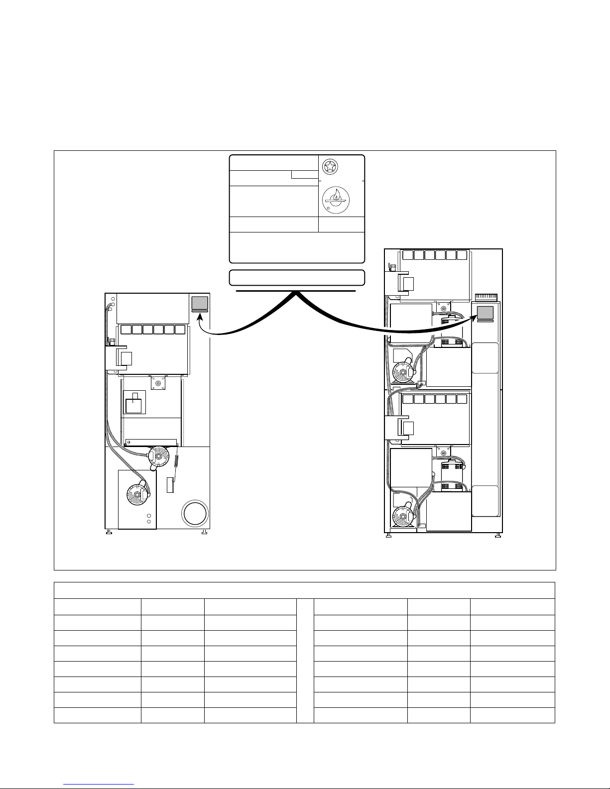
Serial Plate Location
When calling or writing for information about your
product, be sure to mention model and serial numbers.
Model and serial numbers are found on serial plate on
rear of machine, and inside door hinge.
MODEL NO:
SERIAL NO:
V-/ HERTZ/ PHASE
AMPS, WIRES + GROUND
TOTAL kW, MOTOR kW
REQ'D CIRCUIT BREAKER: AMPS
FAN OUTPUT:
@MAX "WC STATIC PRESSURE
EQUIPPED FOR: GAS@ "WC MANIFOLD PRESS.
MIN SUPPLY
PRESSURE:
INPUT: BTU/hr @ BTU/cu.ft.
MADE IN U.S.A./FABRIQUE AU ETATS UNIS/FABRICADO EN LOS ESTADOS UNIDOS 70051001
MODEL NO:
SERIAL NO:
MAX SUPPLY
"WC. "WC.
PRESSURE:
ANS 72152
CLOTHES DRYER.
VOL II
TESTED FOR NATURAL &
LIQUID PETROLEUM GASSES
CGA 72
AMPLFIEDRER
Introduction
25, 30 AND 35 POUND 30 POUND STACKED
Multiply By To Obtain Multiply By To Obtain
Btu .252 kCal Pounds/sq. inch .06895 Bars
Btu 1055 Joules Pounds/sq. inch .070 kg/sq. cm
Inch 25.4 Millimeters Pounds (lbs.) .454 Kilograms
Inches W.C. .036 Pounds/sq. inch Boiler Horsepower 33,479 Btu/hr.
Inches W.C. .249 kPa Boiler Horsepower 34.5 lbs. Steam/hr.
lbf/inch
ft
70223701
2
(psi) .0369 kPa CFM .471 liters/second
3
28.32 Liters kW 3414 Btu/hr.
© Copyright, Alliance Laundry Systems LLC – DO NOT COPY or TRANSMIT
T448I
T448I
Conversion Table
7
Page 10

Notes
8
© Copyright, Alliance Laundry Systems LLC – DO NOT COPY or TRANSMIT
70223701
Page 11
Safety Information
DANGER indicates the presence of a
hazard that will cause severe personal
injury, death, or substantial property
damage if the danger is ignored.
DANGER
WARNING indicates the presence of a
hazard that can cause severe personal
injury, death, or substantial property
damage if the warning is ignored.
WARNING
CAUTION indicates the presence of a
hazard that will or can cause minor
personal injury or property damage if the
caution is ignored.
CAUTION
Precautionary statements (“DANGER,”
“WARNING,” and “CAUTION ”), followed by
specific instructions, are found in this manual and on
machine decals. These precautions are intended for the
personal safety of the operator, user, servicer, and
those maintaining the machine.
IMPORTANT: Warranty is void unless tumbler is
installed according to instructions in this manual.
Installation should comply with minimum
specifications and requirements detailed in this
manual and applicable local gas fitting regulations,
municipal building codes, water supply regulations,
electrical wiring regulations, and any other
relevant statutory regulations. Due to varied
requirements, applicable local codes should be
thoroughly understood and all pre-installation
work arranged for accordingly.
WARNING
Failure to install, maintain, and/or operate
this machine according to manufacturer’s
instructions may result in conditions which
can produce serious injury, death and/or
property damage.
W051
NOTE: The WARNING and IMPORTANT
instructions appearing in this manual are not meant
to cover all possible conditions and situations that
may occur. It must be understood that common
sense, caution and carefulness are factors which
CANNOT be built into this tumbler. These factors
MUST BE supplied by the person(s) installing,
maintaining or operating the tumbler.
Additional precautionary statements (“IMPORTANT”
and “NOTE”) are followed by specific instructions.
IMPORTANT: The word “IMPORTANT” is used
to inform the reader of specific procedures where
minor machine damage will occur if the procedure
is not followed.
NOTE: The word “NOTE” is used to communicate
installation, operation, maintenance or servicing
information that is important but not hazard
related.
70223701
© Copyright, Alliance Laundry Systems LLC – DO NOT COPY or TRANSMIT
Always contact your dealer, distributor, service agent
or the manufacturer on any problems or conditions you
do not understand.
9
Page 12
Safety Information
To reduce the risk of fire, electric shock,
serious injury or death to persons when
using your tumbler, read and follow these
basic precautions:
W359
WARNING
Save These Instructions
Important Safety Instructions
1. Read all instructions before using the tumbler.
2. Refer to the Grounding Instructions for the
proper grounding of the tumbler.
3. Do not dry articles that have been previously
cleaned in, washed in, soaked in, or spotted with
gasoline, dry cleaning solvents, or other
flammable or explosive substances as they give
off vapors that could ignite or explode.
4. Do not allow children to play on or in the
tumbler. Close supervision of children is
necessary when the tumbler is used near children.
This is a safety rule for all appliances.
5. Before the tumbler is removed from service or
discarded, remove the door to the drying
compartment and the door to the lint
compartment.
6. Do not reach into the tumbler if the cylinder is
revolving.
7. Do not install or store the tumbler where it will
be exposed to water and/or weather.
8. Do not tamper with the controls.
9. Do not repair or replace any part of the tumbler,
or attempt any servicing unless specifically
recommended in the user-maintenance
instructions or in published user-repair
instructions that you understand and have the
skills to carry out.
10. Do not use fabric softeners or products to
eliminate static unless recommended by the
manufacturer of the fabric softener or product.
11. To reduce the risk of fire, DO NOT DRY plastics
or articles containing foam rubber or similarly
textured rubberlike materials.
12. Always clean the lint filter daily.
13. Keep area around the exhaust opening and
adjacent surrounding area free from the
accumulation of lint, dust, and dirt.
10
© Copyright, Alliance Laundry Systems LLC – DO NOT COPY or TRANSMIT
14. The interior of the tumbler and the exhaust duct
should be cleaned periodically by qualified
service personnel.
15. If not installed, operated and maintained in
accordance with the manufacturer’s instructions
or if there is damage to or mishandling of this
product’s components, use of this product could
expose you to substances in the fuel or from fuel
combustion which can cause death or serious
illness and which are known to the State of
California to cause cancer, birth defects or other
reproductive harm.
16. Tumbler will not operate with the loading door
open. DO NOT bypass the door safety switch to
permit the tumbler to operate with the door open.
The tumbler will stop tumbling when the door is
opened. Do not use the tumbler if it does not stop
rotating when the door is opened or starts rotating
without pressing or turning the START
mechanism. Remove the tumbler from use and
call the service person.
17. Tumbler will not operate with lint panel open.
DO NOT bypass lint panel safety switch to
permit the tumbler to operate with the lint panel
open.
18. Do not put articles soiled with vegetable or
cooking oil in the tumbler, as these oils may not
be removed during washing. Due to the
remaining oil, the fabric may catch on fire by
itself.
19. To reduce the risk of fire, DO NOT put clothes
which have traces of any flammable substances
such as machine oil, flammable chemicals,
thinner, etc. or anything containing wax or
chemicals such as in mops and cleaning cloths, or
anything dry-cleaned at home with dry-cleaning
solvent in the tumbler.
20. Use the tumbler only for its intended purpose,
drying water-washed fabrics.
21. ALWAYS disconnect the electrical power to the
tumbler before servicing. Disconnect power by
shutting off appropriate breaker or fuse.
22. Install this tumbler according to these
Installation Instructions. All connections for
electrical power, grounding, and gas supply must
comply with local codes and be made by licensed
personnel when required.
70223701
Page 13
Safety Information
23. Remove laundry immediately after tumbler stops.
24. Always read and follow manufacturer’s
instructions on packages of laundry and cleaning
aids. Heed all warnings or precautions. To reduce
the risk of poisoning or chemical burns, keep
them out of reach of children at all times
(preferably in a locked cabinet).
25. Do not tumble fiberglass curtains and draperies
unless the label says it can be done. If they are
dried, wipe out the cylinder with a damp cloth to
remove particles of fiberglass.
26. Always follow the fabric care instructions
supplied by the garment manufacturer.
27. Never operate the tumbler with any guards and/or
panels removed.
28. DO NOT operate the tumbler with missing or
broken parts.
29. DO NOT bypass any safety devices.
30. Solvent vapors from dry-cleaning machines
create acids when drawn through the heater of the
drying unit. These acids are corrosive to the
tumbler as well as to the laundry load being
dried. Be sure make-up air is free of solvent
vapors.
31. Failure to install, maintain, and/or operate this
machine according to the manufacturer’s
instructions may result in conditions which can
produce bodily injury and/or property damage.
WARNING
To reduce the risk of serious injury, install
lockable door(s) to prevent public access to
rear of tumblers.
W055
70223701
© Copyright, Alliance Laundry Systems LLC – DO NOT COPY or TRANSMIT
11
Page 14

Notes
12
© Copyright, Alliance Laundry Systems LLC – DO NOT COPY or TRANSMIT
70223701
Page 15
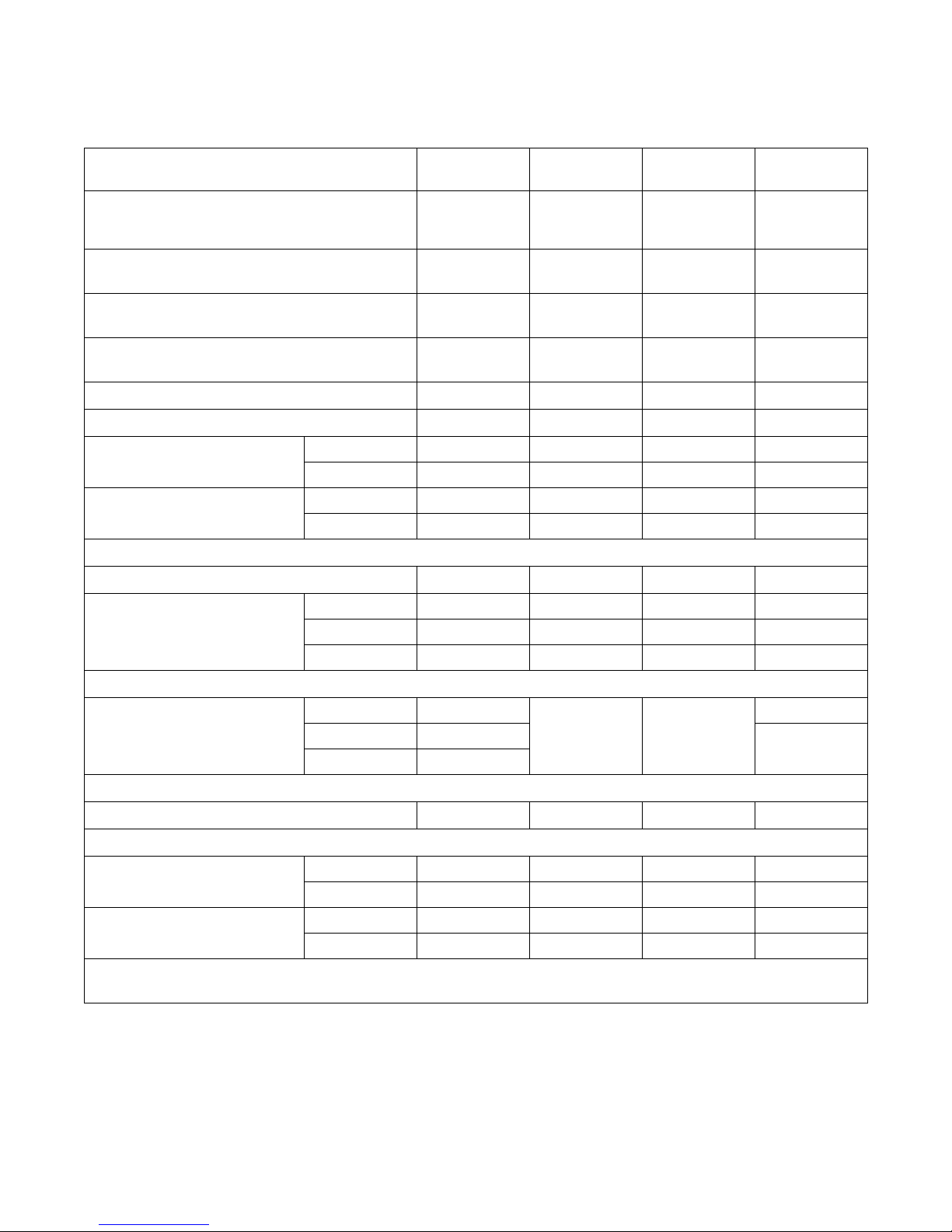
Specifications and Dimensions
Specifications 25 Pound 30 Pound
Noise Level Measured during Operation at
Operator Position of 1 meter in Front of
Machine and 1.6 meters from Floor
Net Weight (approximate):
pounds (kg)
Cylinder Size:
inches (mm)
Cylinder Capacity (dry weight):
pounds (kg)
Drive Motor Horsepower
Fan Motor Horsepower
Maximum Airflow per
Pocket: C.F.M. (L/sec)
Maximum Static Back
Pressure: Inches W.C. (mbar)
Gas Connection
Gas Consumption
50 Hertz 410 (194) 410 (194) 320 (151) 470 (222)
60 Hertz 450 (212) 450 (212) 350 (165) 470 (222)
50 Hertz 0.6 (1.5) 0.6 (1.5) 0.8 (2.0)* 0.5 (1.3)
60 Hertz 0.8 (2.0) 0.8 (2.0) 0.9 (2.3)* 0.6 (1.5)
kW 18.7 21.4 21.4** 26.4
Mj/hr67.57777**95
Btu/hr 64,000 73,000 73,000** 90,000
30 Pound
Stacked
60 dBA 61 dBA 63 dBA 66 dBA
330
(150)
26.5 x 24
(673 x 610)
25
(11.3)
1/4 1/4 1/4** 1/4
1/4 1/4 1/4** 1/4
Gas Models
1/2 in. NPT 1/2 in. NPT 1/2 in. NPT 1/2 in. NPT
350
(159)
26.5 x 30
(673 x 762)
30
(13.6)
575
(261)
30 x 26
(762 x 660)
2 x 30
(2 x 13.6)
35 Pound
360
(163)
30 x 30
(762 x 762)
35
(15.9)
Heating Element
Steam Plumbing
At 80 psig (5.5 bar)
At 15 psig (1.03 bar)
*with both pockets running
**for each pocket
Electric Models
380/50/3 9 kW
400/50/3 10 kW
Standard 12 kW
Steam Models
3/4 in. NPT 3/4 in. NPT 3/4 in. NPT 3/4 in. NPT
Steam Consumption Boiler Horsepower (Btu/hr)
SH Models 3.0 (100,000) 3.0 (100,000) 2.3 (77,000)** 3.4 (113,800)
SL Models 2.4 (80,300) 2.4 (80,300) 1.9 (63,600)** 2.8 (93,700)
SH Models 2.1 (70,300) 2.1 (70,300) 1.6 (53,500)** 2.4 (80,300)
SL Models 1.7 (56,900) 1.7 (56,900) 1.3 (43,500)** 2.0 (67,000)
21 kW 21 kW**
21 kW
24 kW
70223701
© Copyright, Alliance Laundry Systems LLC – DO NOT COPY or TRANSMIT
13
Page 16
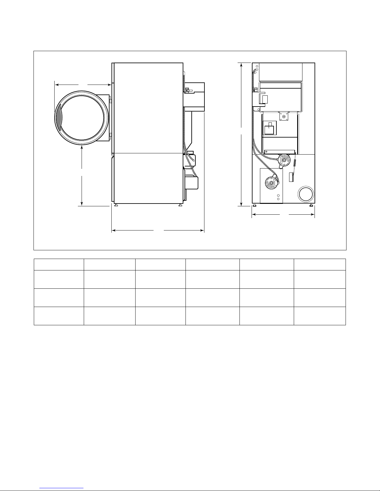
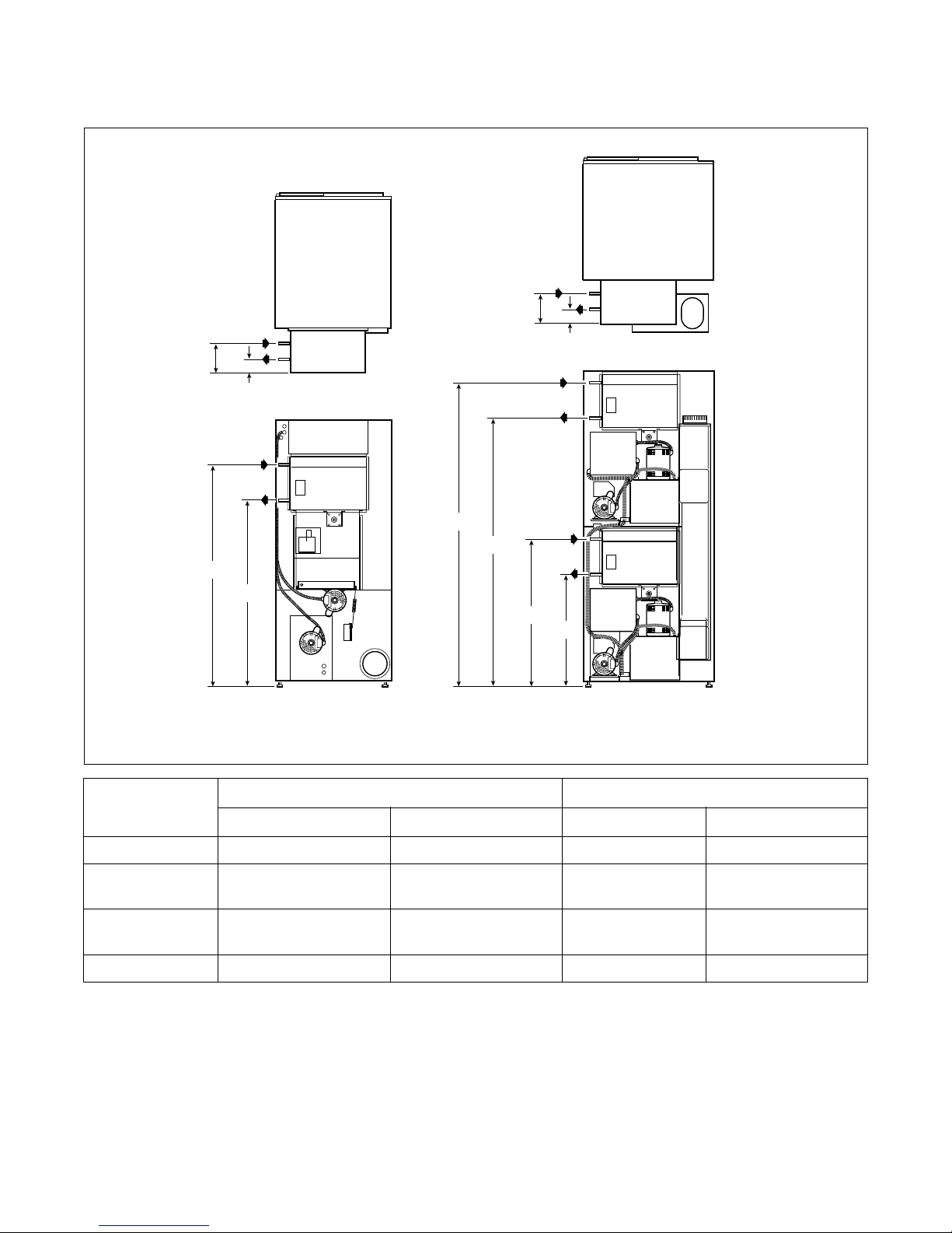
Specifications and Dimensions
Cabinet Dimensions
A
B
D
E
C
Models A B C D E
25 Pound 26.25 in.
(667 mm)
30 Pound 26.25 in.
(667 mm)
35 Pound 28 in.
(711 mm)
27.5 in.
(699 mm)
27.5 in.
(699 mm)
27.5 in.
(699 mm)
38.875 in.
(987 mm)
44.875 in.
(1140 mm)
44.875 in.
(1140 mm)
63.875 in.
(1622 mm)
63.875 in.
(1622 mm)
63.875 in.
(1622 mm)
NOTE: Facia panels available to increase height of
single pocket models to 72.25 inches (1835 mm) and
76.25 inches (1938 mm).
T370I
T370I
28 in.
(711 mm)
28 in.
(711 mm)
31.5 in.
(800 mm)
14
© Copyright, Alliance Laundry Systems LLC – DO NOT COPY or TRANSMIT
70223701
Page 17
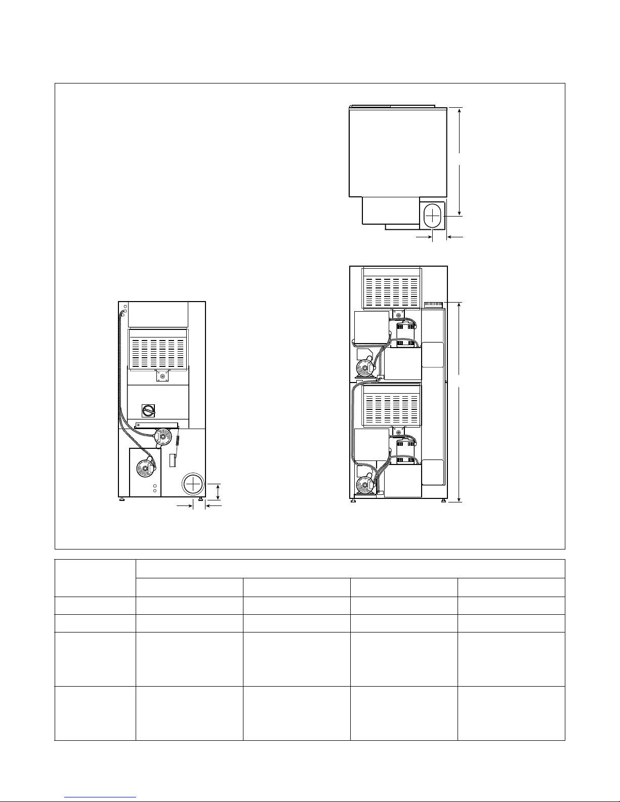
Cabinet Dimensions – Stacked Model
Specifications and Dimensions
B
A
C
D
30 POUND STACKED
E
F
T439I
T439I
ModelsABCDEF
30 Pound
Stacked
48 in.
(1219 mm)
28 in.
(711 mm)
10 in.
(254 mm)
42.875 in.
(1090 mm)
31.5 in.
(800 mm)
76.25 in.
(1937 mm)
70223701
© Copyright, Alliance Laundry Systems LLC – DO NOT COPY or TRANSMIT
15
Page 18
Specifications and Dimensions
Exhaust Outlet Locations
C
A
B
B
A
25, 30 AND 35 POUND 30 POUND STACKED
Rear Exhaust
Models
Diameter A B C
25/30 Pound 6 in. (152 mm) 3.875 in. (99 mm) 4.625 in. (117 mm) N/A
35 Pound 8 in. (203 mm) 4.875 in. (124 mm) 5.625 in. (143 mm) N/A
30 Pound
8 in. (203 mm) 4.875 in. (124 mm) 66.25 in. (1683 mm) 32.63 in. (829 mm)
Stacked
(Manufactured
Before 3/22/99)
T479I
30 Pound
Stacked
Elliptical
Fits 8 in. (203 mm)
(Manufactured
After 3/22/99)
16
© Copyright, Alliance Laundry Systems LLC – DO NOT COPY or TRANSMIT
4.325 in. (110 mm) 64.25 in. (1632 mm) 35.75 in. (908 mm)
70223701
Page 19
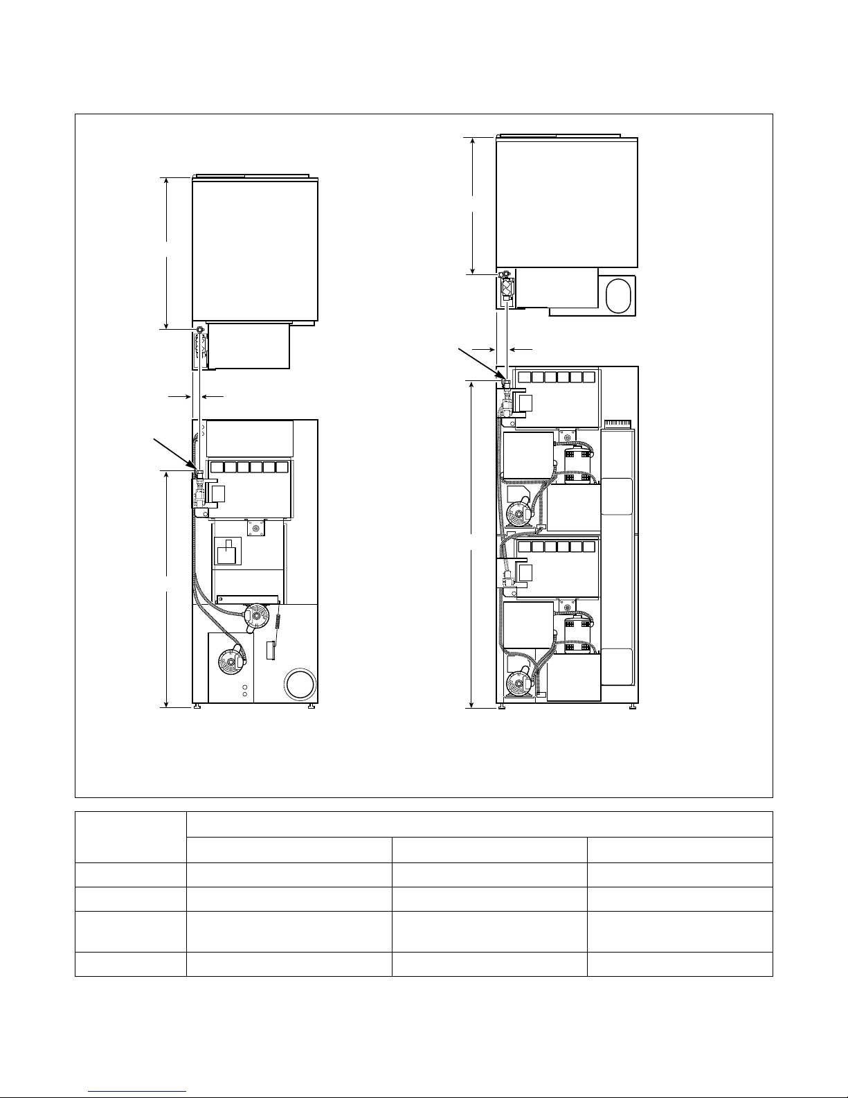
Gas Connection Locations
C
Specifications and Dimensions
C
1
B
1
A
A
25, 30 AND 35 POUND 30 POUND STACKED
B
T482 I
1 1/2 in. NPT
Models
ABC
25 Pound 59 in. (1500 mm) 1.5 in. (38.1 mm) 29 in. (737 mm)
30 Pound 59 in. (1500 mm) 1.5 in. (38.1 mm) 35 in. (889 mm)
30 Pound
80 in. (2032 mm) 2.5 in. (64 mm) 30.5 in. (775 mm)
Stacked
35 Pound 59 in. (1500 mm) 2.5 in. (64 mm) 35 in. (889 mm)
NOTE: All connections use 1/2 inch NPT pipe.
70223701
© Copyright, Alliance Laundry Systems LLC – DO NOT COPY or TRANSMIT
T482I
Gas Connection
17
Page 20
Specifications and Dimensions
Electrical Connection Locations
B
A
30 POUND STACKED
GAS AND STEAM
D
C
C
30 POUND STACKED
ELECTRIC
DB
A
C
T480I
25, 30 AND 35 POUND
GAS AND STEAM
25, 30 AND 35 POUND
ELECTRIC
Electrical Service
Models
Gas and Steam Models Electric Models
ABCD
25/30 Pound 62.25 in. (1581 mm) 2 in. (51 mm) 28 in. (711 mm) 3.25 in. (83 mm)
30 Pound
Stacked
57 in. (1448 mm) 2 in. (51 mm) 48.5 in. (1232 mm)
11.5 in. (292 mm)
7 in. (178 mm)
35 Pound 62.25 in. (1581 mm) 3 in. (76 mm) 28 in. (711 mm) 4.25 in. (108 mm)
T480I
18
© Copyright, Alliance Laundry Systems LLC – DO NOT COPY or TRANSMIT
70223701
Page 21
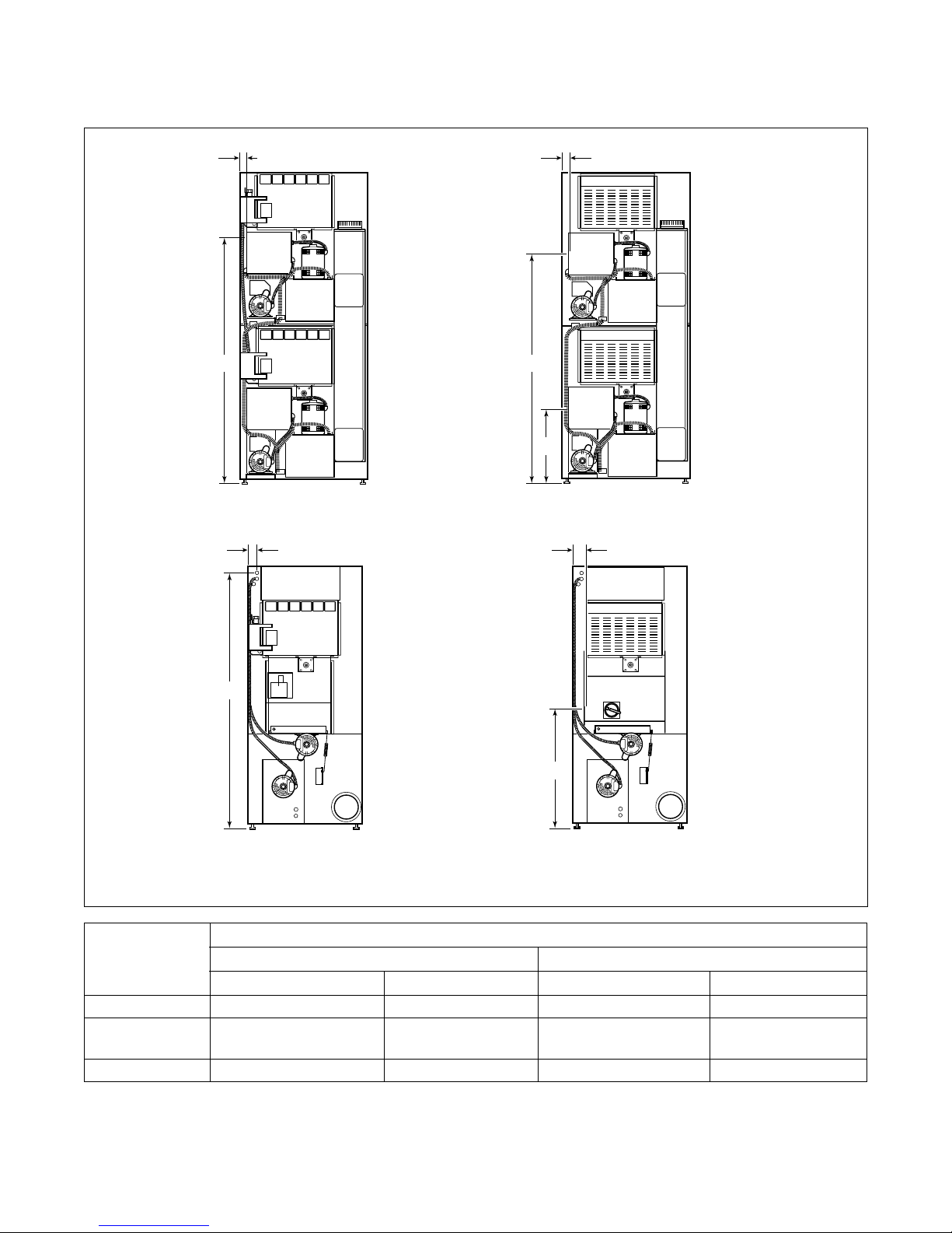
Steam Connection Locations
Specifications and Dimensions
C
C
D
A
B
A
B
25, 30 AND 35 POUND
D
A
B
30 POUND STACKED
T481I
Models
ACBD
25/30 Pound 53.75 in. (1365 mm) 7.8 in. (198 mm) 42.5 in. (1080 mm) 6.5 in. (165 mm)
30 Pound Stacked
74.15 in. (1883 mm) 11.6 in. (295 mm) 62.9 in. (1598 mm) 10.25 in. (260 mm)
(Upper)
30 Pound Stacked
36.6 in. (930 mm) 11.6 in. (295 mm) 25.3 in. (643 mm) 10.25 in. (260 mm)
(Lower)
35 Pound 53.75 in. (1365 mm) 7.8 in. (198 mm) 42.5 in. (1080 mm) 6.5 in. (165 mm)
NOTE: All connections use 3/4 inch NPT pipe.
70223701
© Copyright, Alliance Laundry Systems LLC – DO NOT COPY or TRANSMIT
Inlet Outlet
19
Page 22

Notes
20
© Copyright, Alliance Laundry Systems LLC – DO NOT COPY or TRANSMIT
70223701
Page 23

Installation
IMPORTANT: Warranty is void unless tumbler is
installed according to instructions in this manual.
Installation should comply with minimum
specifications and requirements detailed herein,
and with applicable local gas fitting regulations,
municipal building codes, water supply regulations,
electrical wiring regulations, and any other
relevant statutory regulations. Due to varied
requirements, applicable local codes should be
thoroughly understood and all pre-installation
work arranged for accordingly.
Pre-Installation Inspection
Upon delivery, visually inspect crate carton and parts
for any visible shipping damage. If the crate, carton, or
cover is damaged or signs of possible damage are
evident, have the carrier note the condition on the
shipping papers before the shipping receipt is signed,
or advise the carrier of the condition as soon as it is
discovered.
Remove the crate and protective cover as soon as
possible and check the items listed on the packing list.
Advise the carrier of any damaged or missing articles
as soon as possible. A written claim should be filed
with the carrier immediately if articles are damaged or
missing.
Location Requirements
The tumbler must be installed on a level floor capable
of supporting 100 pounds per square foot
(488.3 kg/sq. m). Floor covering materials such as
carpeting or tile should be removed.
To assure compliance, consult local building code
requirements. The tumbler must not be installed or
stored in an area where it will be exposed to water
and/or weather.
IMPORTANT: DO NOT block the airflow at the
rear of the tumbler with laundry or other articles.
Doing so would prevent adequate air supply to the
combustion chamber of the tumbler.
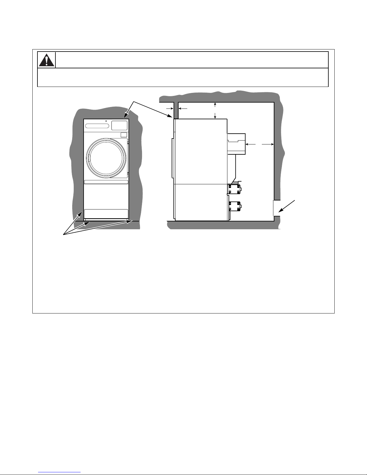
A typical tumbler enclosure is shown in Figure 1. Note
that the enclosure touches the tumbler top and side
panels. Also, note the minimum and maximum
dimensions. Be aware that there may be local codes
and ordinances which must be complied with.
WARNING
To reduce the risk of serious injury, install
lockable door(s) to prevent public access to
rear of tumblers.
W055
Material Required (Obtain Locally)
All Models
Gas Models
Steam
Models
One fused disconnect switch or circuit
breaker.
One gas shut-off valve for gas service
line to each tumbler.
One steam shut-off valve for steam
service line to be connected upstream of
solenoid steam valve.
Two steam shut-off valves for each
condensate return line.
Flexible steam hoses with a 125 psig
(pounds per square inch gauge)
(8.78 kg/sq. cm) working pressure for
connecting steam coils. Refer to
Figure 18 for sizing and connection
configurations.
Two steam traps for steam coil outlet to
condensate return line.
Two vacuum breakers for condensate
return lines.
Table 1
IMPORTANT: Install tumblers with sufficient
clearance for servicing and operation. Refer to
Figure 1.
IMPORTANT: Keep tumbler area clear and free
from combustible materials, gasoline and other
flammable vapors and liquids.
70223701
© Copyright, Alliance Laundry Systems LLC – DO NOT COPY or TRANSMIT
21
Page 24
Installation
Tumbler Enclosure
WARNING
To reduce the risk of severe injury, clearance of tumbler cabinet from combustible
construction must conform to the minimum clearances.
1
W056
2
6
1 Zero Clearance Permitted
2 4 in. (102 mm)
3 12 in. (305 mm) Minimum Clearance
4 24 in. (610 mm) minimum – 36 in. (914 mm) recommended for maintenance purposes.
5 Provision for make-up air: Minimum 1 square foot required per tumbler (2 square feet for stacked model) –
Location for reference only. May be anywhere behind tumbler.
6 Zero Clearance Permitted
NOTE: Shaded areas indicate adjacent structure.
3
4
T484I
5
T484I
22
© Copyright, Alliance Laundry Systems LLC – DO NOT COPY or TRANSMIT
Figure 1
70223701
Page 25
Installation
1
2
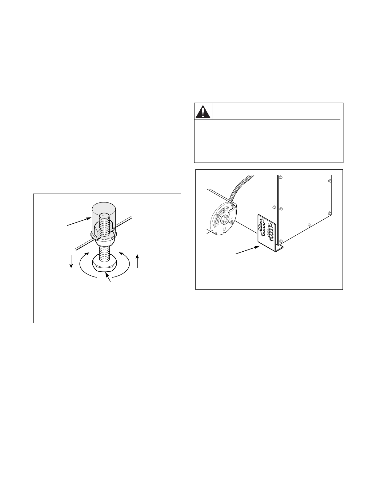
Position and Level the Tumbler
Remove lint panel door, and unscrew the four shipping
bolts (one at each corner). Remove tumbler from skid.
NOTE: Do not throw bolts away – they are the
leveling legs.
Remove four nuts from the literature packet, and screw
one fully onto each leveling leg.
Screw the four leveling legs (bolts) back into the level
adjusting fittings from the bottom.
Slide tumbler to its permanent location. Adjust the
leveling legs until the unit is level within 1/8 inch
(32 mm). Tumbler must not rock. Lock leveling legs
with nuts installed.
IMPORTANT: Keep tumbler as close to floor as
possible. The unit must rest firmly on floor so
weight of tumbler is evenly distributed.
Stacked Tumblers Only:
The stacked tumbler (300D) has a fifth leveling leg
which is enclosed with this manual. It MUST BE
installed on the lower left side of the blower housing to
stabilize the tumbler. Refer to Figure 3.
After leveling with the four cabinet leveling legs,
install the fifth so that it contacts the floor.
CAUTION
The stacked drying tumbler has a 5th
leveling leg on the blower housing. It is
very important to properly adjust this leg.
Unit is back heavy and could rock or tip.
W250
1
T467I
T467I
T451I
T451I
1 Plastic Cap
2 Leveling Leg
Figure 2
1 Fifth Leg
Figure 3
70223701
© Copyright, Alliance Laundry Systems LLC – DO NOT COPY or TRANSMIT
23
Page 26
Installation
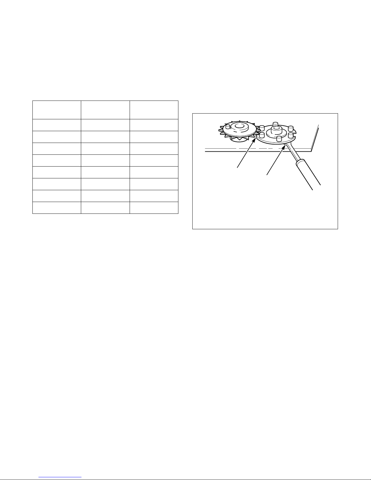
Installing Accessory Timing Cam
(Metered Models)
Coin Drop tumblers have eight accessory cams in the
literature packet. These allow you to change your
vending times. Refer to Table 2. Timer motor RPM is
printed on the timer motor.
Cam Pins
21530
31020
47.515
5612
6510
8 3.75 7.5
10 3 6
12 2.5 5
1/30 RPM
Timer Motor
Table 2
1/60 RPM
Timer Motor
Installation of New Timing Cam
1. Insert drive into timing cam with wide prong in
wide hole of cam.
2. Position timing cam and drive fork over the timer
shaft, aligning the timer flat with the drive fork
and the “V” notch with one of the ratchet teeth.
3. Press timing cam down firmly to seat timing cam
onto the motor shaft.
1
2
T039I
T039I
1 Line up notch to clear ratchet tooth.
2 Lift gently with narrow blade.
Removal of Existing Timing Cam
1. Rotate cam by hand until “V” notch lines up
beneath the ratchet tooth. Refer to Figure 4.
2. Insert narrow screwdriver under nylon cam, close
to the clock shaft. Lift gently off shaft. Make sure
that pressure is directed upward and that the “V”
notch clears the ratchet tooth.
Figure 4
4. Remove all accumulated time by turning cam
counterclockwise until switch shuts off. Apply
moderate clockwise pressure to fully seated
timing cam and drive against the timing motor
shaft. Meter must be advanced electrically for
one cycle before an accurate measure of time can
be made.
24
© Copyright, Alliance Laundry Systems LLC – DO NOT COPY or TRANSMIT
70223701
Page 27
Installation
Before Placing Tumbler into Service
1. Remove or open all panels and check accessible
bolts, nuts, screws, terminals, and fittings for
tightness.
2. Replace all panels and guards.
3. Turn on electrical supply to tumbler.
4. Open the supply valve for gas or steam heated
tumblers.
5. After performing the previous checks, start the
tumbler by pressing START. (Refer to the
Operating Manual for detailed instructions.)
Release the start button and open the cylinder
door. The cylinder should stop rotating within
seven seconds after the door is opened a
maximum of 2 inches (51 mm). If it does not,
adjust the cylinder door switch. Refer to
Adjustments section.
IMPORTANT: The electronic ignition system will
attempt to light the gas by sparking for the “trial
for ignition” period (refer to Tab le 3). If gas does
not ignite within this period, the ignition control
will go into a safety lockout and the valve will no
longer open until the control is reset. It may be
necessary to retry several times to bleed air from
the gas lines. To reset, open and close the loading
door and restart tumbler.
7. Check the airflow switch operation by opening
the lint panel. The heating systems should shut
off when the lint panel is opened a maximum of
1-1/2 inches (38 mm).
The airflow switch operation may be affected by
shipping tape still in place, lack of make-up air,
or an obstruction in the exhaust duct. These
should be checked and the required corrective
action taken before attempting to adjust the
airflow switch.
WARNING
The tumbler must not be operated if the
airflow switch does not operate properly.
Faulty airflow switch operation may cause
an explosive gas mixture to collect in the
tumbler.
W072
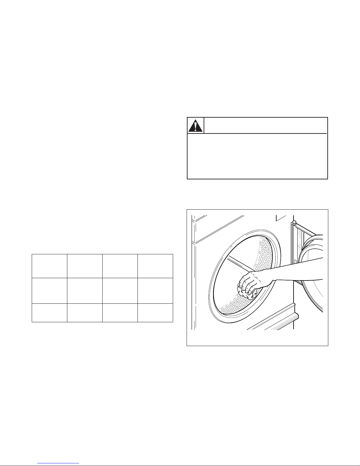
8. Wipe out the cylinder using an all-purpose
cleaner or detergent and water solution. Refer to
Figure 5.
Location
Europe and
Australia
All others 1-3 10 Open loading
Prepurge
Time
(seconds)
18 10 Press reset
Trial for
Ignition
(seconds)
Table 3
To Reset
Lockout
Condition:
button on rear
of machine
door
If lockout condition persists, check that the manual
gas shut-off valve is in the “ON” position and that
the gas service is properly connected. If condition
still persists, remove tumbler from service.
6. Load the cylinder with a full load of clean rags
and run to remove oil or dirt from cylinder.
T452I
T452I
Figure 5
If the tumbler does not meet ANY of the above
requirements, remove tumbler from use. Refer to
Removing Tumbler from Service section.
70223701
© Copyright, Alliance Laundry Systems LLC – DO NOT COPY or TRANSMIT
25
Page 28

Installation
Required for CE Marked (European)
Models Only
Once machine is installed, please be sure to complete
the following items:
● Review and verify machine operation with
customer.
● Leave Operating Instructions and a signed
Declaration of Conformity with customer.
● Leave Model Number Insert with customer, if
applicable.
● Review machine warranty information with
customer.
● Apply warning sticker on front panel of machine,
in language appropriate to country of sale (found
in literature packet).
26
© Copyright, Alliance Laundry Systems LLC – DO NOT COPY or TRANSMIT
70223701
Page 29
Installation
WARNING
To reduce the risk of electric shock, fire,
explosion, serious injury or death:
• Disconnect electric power to the
tumbler before servicing.
• Close gas shut-off valve to gas tumbler
before servicing.
• Close steam valve to steam tumbler
before servicing.
• Never start the tumbler with any guards/
panels removed.
• Whenever ground wires are removed
during servicing, these ground wires
must be reconnected to ensure that the
tumbler is properly grounded.
W002
Installing Gas Drying Tumblers in
the European Union
General Information
This information is to be used when installing gas
tumblers in countries, and/or on gases, different than
the machine’s factory configuration. Tumblers are
supplied from the factory for operation on Natural Gas
or L.P. Gas in the countries of GB/IE/PT/ES/IT. To
install machines in any other country, or on any other
gas, requires some level of modification.
Orifices, stickers, block-open kits, regulator springs
and other parts needed for conversions are to be
ordered separately.
Models are built in three different configurations:
● Regulated Natural Gas – Injector is sized for
Natural Gas, second family, group H (E) at
20 mbar inlet pressure. Regulator/governor is
operational. Gas valve CAN be field-converted to
a non-regulating type.
● Unregulated Natural Gas – Injector is sized for
Natural Gas, second family, group E+ at
20.25 mbar inlet pressure. Regulator/governor is
blocked open. Gas valve CANNOT be fieldconverted to a regulating type.
● Unregulated L.P. (Liquefied Petroleum) Gas –
Injector is sized for L.P., third family, group 3+ at
28.37 mbar inlet pressure. Regulator/governor is
blocked open. Gas valve CANNOT be fieldconverted to a regulating type.
Serial plates supplied from the factory are configured
for the countries of GB/IE/PT/ES/IT. These
instructions pertain to the situations when the country
of use or gas supply is different than that on the serial
plate.
The tables referred to describe the different gases that
are available in different EU countries, and how the
machines need to be configured to operate with those
gases. In the EU, there are Natural Gases that do not
allow for machine regulation, and L.P. Gases that must
be regulated. For L.P. Gas, third family B/P at
50 mbar, order Regulated Natural Gas machines and
convert according to tables.
70223701
© Copyright, Alliance Laundry Systems LLC – DO NOT COPY or TRANSMIT
27
Page 30

Installation
WARNING
When converting the tumbler to a
different gas or pressure, first verify that
the supply inlet pressure is equipped with
a pressure regulator (located ahead of the
tumbler) that will maintain the gas supply
at the inlet pressure specified.
W430
Basic Configuration
1. Determine the necessary conversion operations to
convert from the factory-supplied configuration
to the desired configuration.
2. Perform the conversions required so the machine
is properly configured for the desired country and
gas (refer to Specific Conversion Procedures
section):
● How to Convert Gas Valve from Regulated to
Unregulated
NOTE: Conversion from regulated to unregulated
is only needed when regulated tumblers were
ordered, but unregulated tumblers were needed.
● How to Change Injector (Orifice) Size
● How to Adjust Gas Valve Governor/Regulator
● How to Change Regulator Spring DE/AT
Only.
3. If applicable, peel off the appropriate country
sticker from Part No. 503382 or M413919
(included with machine) and apply it to the serial
plate over the existing country information. Refer
to Figure 9.
4. If applicable, peel off the appropriate conversion
sticker from Part No. M413800 or M413919
(included with machine) and apply it to the serial
plate over the “ADJUSTED FOR ______ GAS:
______” information. Refer to Figure 9.
SPECIFIED
LOCAL INLET
PRESSURE
2
3
1
1 Gas Shut-Off Valve (Ahead of pressure tap)
2 Pressure Tap
3 Gas Shut-Off Valve (Shown in closed position)
Figure 6
T103K
5. Commission tumbler for use.
28
© Copyright, Alliance Laundry Systems LLC – DO NOT COPY or TRANSMIT
70223701
Page 31

Installation
Specific Conversion Procedures
How to Convert Gas Valve from Regulated to
Unregulated
Johnson GM7000 gas valve:
1. Disconnect electrical power from tumbler. Close
gas shut-off valve to tumbler. Refer to Figure 7.
2. Follow instructions in Conversion Kit, Part No.
431485 (Johnson Part No. GM-70 CBP).
11
10
NOTE: This kit does not contain any orifices.
3. Change injector size as required by the
appropriate table according to How to Change
Injector (Orifice) Size.
4. For 220 steam models, L.P. Gas only. Install 220
steam L.P. orifice plate (Part No. 70201901) onto
gas valve bracket. Refer to Figure 7.
5. Commission tumbler for use.
1
2
3
4
9
5
8
7
6
T154K
T154K
1 Gas Shut-Off Valve (Shown in closed position) 7 Part No. 70201901 220 Steam LP Orifice Plate
2 Shut-Off Valve
3 Gas Valve 8 Required Orifice/Injector Pressure
4 Orifice/Injector 9 Manometer
5 Regulator Adjusting Housing and Gasket
(Regulated version shown)
6 Gas Valve Bracket 11 Spud Holder
10 Connect Over Loosened Slotted Pressure Tap
(For use on 220 steam models LP only)
in Bottom of Gas Valve
70223701
© Copyright, Alliance Laundry Systems LLC – DO NOT COPY or TRANSMIT
Figure 7
29
Page 32

Installation
1
BURNER INJECTOR
(ORIFICE)
How to Change Injector (Orifice) Size
1. Disconnect electrical power from tumbler. Close
gas shut-off valve to tumbler. Refer to Figure 7.
2. For Johnson GM7000 gas valve:
Remove spud holder assembly from gas valve
and remove burner orifice from the spud holder.
Refer to Figure 7.
3. Install the new, correct injector(s) (orifices).
Refer to Figure 8. Torque each to 9 – 10 Nm.
4. Reinstall spud holder assembly to gas valve,
making certain orifice is in line with burner tube
opening, and flange gasket is in place in flange
groove. Refer to Figure 7 or Figure 8.
5. Commission tumbler for use.
NOTE: Blank injectors (orifices) are available as
Part No. M400995.
How to Adjust Gas Valve Governor/Regulator
1. Check gas injector (manifold) pressure as
follows. Refer to Figure 7.
How to Change Regulator Spring, DE/AT
Only
1. Disconnect electrical power from tumbler. Close
gas shut-off valve to tumbler. Refer to Figure 6
and Figure 7.
2. Follow instructions in kit Part No. 431559.
3. Adjust injector (manifold) pressure according to
applicable table and How to Adjust Gas Valve
Governor/Regulator section.
4. Install old regulator cap.
5. Commission tumbler for use.
Loosen screw plug inside pressure tap located on
underside of valve.
Connect a “U”-tube manometer (or similar
pressure gauge) to the injector (manifold)
pressure tap.
2. Start tumbler and note pressure once flame is
burning. Remove regulator cap and adjust
regulator screw until the injector pressure per
applicable table is achieved. Replace regulator
cap.
3. Commission tumbler for use.
T025K
T025KE1D
1 Size Stamped on Orifice
Figure 8
30
© Copyright, Alliance Laundry Systems LLC – DO NOT COPY or TRANSMIT
70223701
Page 33

Installation
NOTE: In addition to directions below, follow all
instructions in this section, including verification
and adjustment of injector pressure.
1 – Order as Regulated Natural Gas. No modification
needed.
2 – Order as Regulated Natural Gas. Apply
appropriate country sticker.
3 – Order as Regulated Natural Gas. Apply
appropriate country and gas stickers.
4 – Order as Unregulated with Unregulated Natural
Gas injector. Apply appropriate country sticker.
5 – Order as Unregulated with L.P. Gas injectors.
Apply appropriate country sticker.
6 – Order as Regulated Natural Gas. Apply
appropriate country and gas stickers.
Model 0220SFG: Convert with (1) 50 mbar
regulator spring kit Part No. 431559 and (1)
2.3 mm injector Part No. M406184.
Model 0220SRG: Convert with (1) 50 mbar
regulator spring kit Part. No. 431559 and (1)
2.1 mm injector Part No. M401003.
Model 0270SFG: Convert with (1) 50 mbar
regulator spring kit Part No. 431559 and (1)
2.45 mm injector Part No. M401015.
Model 0270SRG: Convert with (1) 50 mbar
regulator spring kit Part. No. 431559 and (1)
2.2 mm injector Part No. M401011.
Model 0300DFG: Convert with (2) 50 mbar
regulator spring kits Part No. 431559 and (2)
2.45 mm injectors Part No. M401015.
Model 0300DRG: Convert with (2) 50 mbar
regulator spring kits Part No. 431559 and (2)
2.2 mm injectors Part No. M401011.
Model 0350SFG: Convert with (1) 50 mbar
regulator spring kit Part No. 431559 and (1)
2.7 mm injector Part No. M411375.
Model 0350SRG: Convert with (1) 50 mbar
regulator spring kit Part No. 431559 and (1)
2.5 mm injector Part No. M406361.
7 – Order as Unregulated with L.P. Gas injectors. No
modification needed.
8 – Order as Unregulated with L.P. Gas injectors.
Apply appropriate country sticker.
OPEN – No Approval available.
Special Cases – Regulated Gas Valve may be
converted to Unregulated with block-open kit Part
No. 431485.
Model: 0220SFG Input: 21.9 kW Flue Code: B
Gas
GB IE PT ES IT DK NO SE FI DE NL BE FR AT
Typ e
1111122222 2
Nat.
Gas
555555
L.P.
Gas
77777 88
3
66
Table 4
44
Gas
Family &
Group
2nd family
Group H
(E)
2nd family
Group L
(LL)
2nd family
Group E+
3rd family
Group B/P
3rd family
Group B/P
3rd family
Group 3+
22
Inject. 0
4.0 mm
4.0 mm
3.3 mm
2.3 mm
2.3 mm
2.3 mm
Inject. Qty &
Part. No.
1
M402996
1
M402996
1
M410021
1
M406184
1
M406184
1
M406184
Inlet
20.25
mbar
28.37
mbar
Gvnr./
Regltr.
Press.
20 mbar Yes 8.9 mbar
25 mbar Yes 13.5 mbar
30 mbar No Unreg.
50 mbar Yes 28.7 mbar
Inject.
Press.
No Unreg.
No Unreg.
70223701
© Copyright, Alliance Laundry Systems LLC – DO NOT COPY or TRANSMIT
31
Page 34

Installation
Model: 0270SFG Input: 25.8 kW Flue Code: B
Gas
GB IE PT ES IT DK NO SE FI DE NL BE FR AT
Typ e
1111122222 2
Nat.
Gas
555555
L.P.
Gas
77777 88
3
66
44
Family &
Group
2nd family
Group H
2nd family
Group L
2nd family
Group E+
3rd family
Group B/P
3rd family
Group B/P
3rd family
Group 3+
Table 5
Model: 0300DFG Input: 2 x 25.8 kW Flue Code: B
Gas
GB IE PT ES IT DK NO SE FI DE NL BE FR AT
Typ e
1111122222 2
Nat.
Gas
555555
L.P.
Gas
77777 88
3
66
Table 6
44
Family &
Group
2nd family
Group H
2nd family
Group L
2nd family
Group E+
3rd family
Group B/P
3rd family
Group B/P
3rd family
Group 3+
Gas
(E)
(LL)
Gas
(E)
(LL)
22
22
Inject. 0
4.6 mm
4.6 mm
3.6 mm
2.45 mm
2.45 mm
2.45 mm
Inject. 0
4.6 mm
4.6 mm
3.6 mm
2.45 mm
2.45 mm
2.45 mm
Inject. Qty
& Part. No.
1
M411511
1
M411511
1
M401014
1
M401015
1
M401015
1
M401015
Inject. Qty
& Part. No.
2
M411511
2
M411511
2
M401014
2
M401015
2
M401015
2
M401015
Inlet
20.25
mbar
28.37
mbar
Inlet
20.25
mbar
28.37
mbar
Gvnr./
Regltr.
Gvnr./
Regltr.
Press.
20 mbar Yes 7.6 mbar
25 mbar Yes 11 mbar
30 mbar No Unreg.
50 mbar Yes 28 mbar
Press.
20 mbar Yes 7.6 mbar
25 mbar Yes 11 mbar
30 mbar No Unreg.
50 mbar Yes 28 mbar
Inject.
Press.
No Unreg.
No Unreg.
Inject.
Press.
No Unreg.
No Unreg.
Model: 0350SFG Input: 31.4 kW Flue Code: B
Gas
32
GB IE PT ES IT DK NO SE FI DE NL BE FR AT
Typ e
1111122222 2
Nat.
Gas
555555
L.P.
Gas
77777 88
3
66
Table 7
© Copyright, Alliance Laundry Systems LLC – DO NOT COPY or TRANSMIT
44
Family &
2nd family
2nd family
2nd family
3rd family
Group B/P
3rd family
Group B/P
3rd family
22
Gas
Group
Group H
(E)
Group L
(LL)
Group E+
Group 3+
Inject. 0
5.0 mm
5.0 mm
4.0 mm
2.7 mm
2.7 mm
2.7 mm
Inject. Qty
& Part. No.
1
70070901
1
70070901
1
M402996
1
M411375
1
M411375
1
M411375
Inlet
20.25
mbar
28.37
mbar
Gvnr./
Regltr.
Press.
20 mbar Yes 8.9 mbar
25 mbar Yes 12.5 mbar
30 mbar No Unreg.
50 mbar Yes 28.3 mbar
Inject.
Press.
No Unreg.
No Unreg.
70223701
Page 35

Installation
Model: 0220SRG Input: 18.8 kW Flue Code: B
Gas
GB IE PT ES IT DK NO SE FI DE NL BE FR AT
Typ e
1111122222 2
Nat.
Gas
555555
L.P.
Gas
77777 88
3
66
44
Family &
Group
2nd family
Group H
2nd family
Group L
2nd family
Group E+
3rd family
Group B/P
3rd family
Group B/P
3rd family
Group 3+
Table 8
Model: 0270SRG Input: 21.4 kW Flue Code: B
Gas
GB IE PT ES IT DK NO SE FI DE NL BE FR AT
Typ e
1111122222 2
Nat.
Gas
555555
L.P.
Gas
77777 88
3
66
Table 9
44
Family &
Group
2nd family
Group H
2nd family
Group L
2nd family
Group E+
3rd family
Group B/P
3rd family
Group B/P
3rd family
Group 3+
Gas
(E)
(LL)
Gas
(E)
(LL)
22
22
Inject. 0
3.9 mm
3.9 mm
3.1 mm
2.1 mm
2.1 mm
2.1 mm
Inject. 0
4.0 mm
4.0 mm
3.3 mm
2.2 mm
2.2 mm
2.2 mm
Inject. Qty
& Part. No.
1
M402980
1
M402980
1
70202701
1
M401003
1
M401003
1
M401003
Inject. Qty
& Part. No.
1
M402992
1
M402992
1
M401021
1
M401011
1
M401011
1
M401011
Inlet
20.25
mbar
28.37
mbar
Inlet
20.25
mbar
28.37
mbar
Gvnr./
Regltr.
Gvnr./
Regltr.
Press.
20 mbar Yes 8.0 mbar
25 mbar Yes 11.5 mbar
30 mbar No Unreg.
50 mbar Yes 28.7 mbar
Press.
20 mbar Yes 8.0 mbar
25 mbar Yes 11.8 mbar
30 mbar No Unreg.
50 mbar Yes 28.9 mbar
Inject.
Press.
No Unreg.
No Unreg.
Inject.
Press.
No Unreg.
No Unreg.
Model: 0300DRG Input: 2 x 21.4 kW Flue Code: B
Gas
Typ e
Nat.
Gas
L.P.
Gas
70223701
GB IE PT ES IT DK NO SE FI DE NL BE FR AT
1111122222 2
3
44
555555
66
77777 88
Tab le 1 0
© Copyright, Alliance Laundry Systems LLC – DO NOT COPY or TRANSMIT
Family &
2nd family
2nd family
2nd family
3rd family
Group B/P
3rd family
Group B/P
3rd family
22
Gas
Group
Group H
(E)
Group L
(LL)
Group E+
Group 3+
Inject. 0
4.0 mm
4.0 mm
3.3 mm
2.2 mm
2.2 mm
2.2 mm
Inject. Qty
& Part. No.
2
M402992
2
M402992
2
M401021
2
M401011
2
M401011
2
M401011
Inlet
20.25
mbar
28.37
mbar
Gvnr./
Regltr.
Press.
20 mbar Yes 8.0 mbar
25 mbar Yes 11.8 mbar
30 mbar No Unreg.
50 mbar Yes 28.9 mbar
Inject.
Press.
No Unreg.
No Unreg.
33
Page 36

Installation
Model: 0350SRG Input: 26.4 kW Flue Code: B
Gas
GB IE PT ES IT DK NO SE FI DE NL BE FR AT
Typ e
1111122222 2
Nat.
Gas
555555
L.P.
Gas
77777 88
3
66
Tab le 1 1
44
Family &
Group
2nd family
Group H
2nd family
Group L
2nd family
Group E+
3rd family
Group B/P
3rd family
Group B/P
3rd family
Group 3+
Gas
(E)
(LL)
22
Inject. 0
4.6 mm
4.6 mm
3.7 mm
2.5 mm
2.5 mm
2.5 mm
Inject. Qty
& Part. No.
1
M411511
1
M411511
1
M400998
1
M406361
1
M406361
1
M406361
Inlet
20.25
mbar
28.37
mbar
Gvnr./
Regltr.
Press.
20 mbar Yes 8.0 mbar
25 mbar Yes 12.0 mbar
30 mbar No Unreg.
50 mbar Yes 28.1 mbar
Inject.
Press.
No Unreg.
No Unreg.
34
© Copyright, Alliance Laundry Systems LLC – DO NOT COPY or TRANSMIT
70223701
Page 37

LOCATED
HERE
Installation
44001907
T369IE1A
APPLICATION OF STICKERS TO SERIAL PLATE
70223701
© Copyright, Alliance Laundry Systems LLC – DO NOT COPY or TRANSMIT
Figure 9
35
Page 38

Notes
36
© Copyright, Alliance Laundry Systems LLC – DO NOT COPY or TRANSMIT
70223701
Page 39

Exhaust Requirements
A drying tumbler produces combustible
lint. To reduce the risk of fire, the tumbler
must be exhausted to the outdoors.
W057
To reduce the risk of fire and accumulation
of combustible gases, DO NOT exhaust
tumbler air into a window well, gas vent,
chimney or enclosed, unventilated area
such as an attic wall, ceiling, crawl space
under a building, or concealed space of a
building.
W059
WARNING
Make-up air openings for a room containing
tumbler(s) and/or gas fired hot water heater or other
gravity vented appliances must be increased
sufficiently to prevent downdrafts in any of the vents
when all tumblers are in operation. Do not locate
gravity vented appliances between tumbler(s) and
make-up air openings. If it is necessary to duct makeup air to the tumbler(s), increase the area of the
ductwork by 25% to compensate for any restriction in
air movement.
Venting
For maximum efficiency and minimum lint
accumulation, tumbler air must be exhausted to the
outdoors by the shortest possible route.
Layout
Whenever possible, install tumblers along an outside
wall where duct length can be kept to a minimum, and
make-up air can be easily accessed. Elbows and long
vents tend to increase drying time. Construction must
not block the airflow at the rear of the tumbler. Doing
so would prevent adequate air supply to the tumbler’s
combustion chamber.
Make-Up Air
A tumbler is forced air exhausted and requires
provisions for make-up air to replace the air exhausted
by the tumbler.
IMPORTANT: Do not obstruct the flow of
combustion and ventilation air.
Make-up air openings should be as close to the
tumbler(s) as possible.
The required make-up air opening to the outside for
each
tumbler is:
144 square inches (928 sq. cm) for 25, 30 and
35 pound tumbler models
288 square inches (1856 sq. cm) for 30 pound
stacked tumbler models
Make-up air openings with louvers will restrict
airflow. The opening must be increased to compensate
for area taken up by louvers.
70223701
© Copyright, Alliance Laundry Systems LLC – DO NOT COPY or TRANSMIT
Proper sized exhaust ducts are essential for proper
operation. All elbows should be sweep type. Exhaust
ducts must be assembled so the interior surfaces are
smooth, so the joints do not permit the accumulation
of lint.
DO NOT use plastic or thin foil flexible ducts. Use
exhaust ducts made of sheet metal or other
noncombustible material. Use metal duct tape on all
joints.
Verify that old ducts are thoroughly cleaned out before
installing new tumbler.
Improperly sized or assembled ductwork causes
excess back pressure which results in slow drying, lint
collecting in the duct, lint blowing into the room, and
increased fire hazard.
Exhaust ducts shall be constructed of sheet metal
or other noncombustible material. Such ducts must
be equivalent in strength and corrosion resistance
to ducts made of galvanized sheet steel not less than
0.0195 inches (0.495 mm) thick.
Where the exhaust duct pierces a combustible wall,
ceiling, floor or partition an opening having a diameter
of 4 inches (102 mm) larger than the diameter of the
exhaust duct shall be provided, with the duct centered
in the opening. The space around the duct may be
sealed with noncombustible material. Refer to
Figure 10.
IMPORTANT: For best performance provide an
individual exhaust duct for each tumbler. Do not
install a hot water heater in room containing
tumblers. It is better to have the water heater in a
separate room with a separate air inlet.
37
Page 40

Exhaust Requirements
Individual Venting
For maximum efficiency and performance, it is
preferred to exhaust tumbler(s) individually to the
outdoors.
IMPORTANT: At no point may the cross sectional
area of installed venting be less than the cross
sectional area of the exhaust outlet of the tumbler.
The exhaust duct must be designed so the static back
pressure measured 12 inches (305 mm) from the
exhaust outlet does not exceed the maximum
allowable pressure specified on the installation sticker
on the rear of the tumbler. Static back pressure must be
measured with the tumbler running (both pockets on
stacked models).
Duct
Diameter
6 in. (152 mm)
8 in. (203 mm)
10 in. (254 mm)
12 in. (305 mm)
14 in. (355.6 mm)
16 in. (406.4 mm)
18 in. (457.2 mm)
Equivalent Length of
Straight Duct
One 90° elbow = 7 ft. (2.1 m)
One 90° elbow = 9.3 ft. (2.83 m)
One 90° elbow = 11.6 ft. (3.5 m)
One 90° elbow = 14 ft. (4.3 m)
One 90° elbow = 16 ft. (4.9 m)
One 90° elbow = 18.7 ft. (5.7 m)
One 90° elbow = 21 ft. (6.4 m)
Equivalent Length (feet) = 1.17 x Duct Diameter (inches)
Table 12
Example: A 12 inch diameter duct’s equivalent
length of 14 feet of duct and two 90° elbows is:
The maximum allowable length venting of the same
diameter as the exhaust thimble is 14 feet (4.3 meters)
and two 90° elbows or equivalent. If the equivalent
length of a duct required for an installation exceeds the
maximum allowable equivalent length, the diameter of
a round duct must be increased by 10% for each
additional 20 feet (6.1 meters). Cross section area of a
rectangular duct must be increased by 20% for each
additional 20 feet (6.1 meters). Table 12 shows how to
determine equivalent venting.
1
6
2
CONNECT TO
TUMBLER
Equivalent Length = 14 feet + (2) 90° elbows
= 14 feet + 14 feet + 14 feet
= 42 feet (12.8 meters)
With the tumbler (both pockets on stacked models) in
operation, airflow at any point in the duct should be at
least 1200 feet per minute (366 meters per meter) to
ensure that lint remains airborne. If 1200 feet per
minute cannot be maintained, schedule a regular
inspection and cleaning of the ductwork.
2
CONNECT TO TUMBLER
5
4
EXHAUST
OUTLET
3
1
3
VERTICAL EXHAUST INSTALLATION HORIZONTAL EXHAUST INSTALLATION
1 No Screen or Cap
2 Wall
3 2 in. (51 mm) Minimum Clearance
4 NOTE: Where exhaust duct pierces a combustible wall or ceiling, an opening having a diameter 4 in. (102 mm)
larger than diameter of exhaust duct shall be provided, with exhaust duct centered in opening.
5 Exhaust Airflow – Maximum Length of Duct: 14 ft. (4.3 m)
6 Minimum Distance Between Opening and Roof: 36 in. (914 mm)
38
© Copyright, Alliance Laundry Systems LLC – DO NOT COPY or TRANSMIT
4
TMB1379N
TMB1379N
Figure 10
70223701
Page 41

Exhaust Requirements
Manifold Venting
While it is preferable to exhaust tumblers individually
to the outdoors, a main collector duct may be used if it
is sized according to Figure 12. This illustration
indicates minimum diameters, which should be
increased if the collector length exceeds 14 feet and
two 90° elbows. The diameter of a round duct must be
increased by 10% for each additional 20 feet
(6.1 meters). Cross sectional area of a rectangular or
square duct must be increased 20% for each additional
20 feet (6.1 meters). Refer to Table 12 to determine
equivalent ducting sizing. The collector duct may be
rectangular or square in cross section, as long as the
area is not reduced. Provisions MUST be made for lint
removal and cleaning of the collector duct.
The vent collector system must be designed so the
static back pressure measured 12 inches (305 mm)
from the exhaust outlet does not exceed the maximum
allowable pressure specified on the installation sticker
on the rear of tumbler. Static back pressure must be
measured with all tumblers vented into the collector
operating.
Never connect a tumbler duct at a 90° angle to the
collector duct (refer to Figure 11). Doing so will
cause excessive back pressure, resulting in poor
performance. Never connect two tumbler exhaust
ducts directly across from each other at the point of
entry to the collector duct.
With the tumbler (both pockets on stacked models) in
operation, airflow at any point in the duct should be at
least 1200 feet per minute (366 meters per minute) to
ensure that lint remains airborne. If 1200 feet per
minute cannot be maintained, schedule a regular
inspection and cleaning of the ductwork.
The collector system must be designed so the static
back pressure measured 12 inches (305 mm) from
the exhaust outlet does not exceed the maximum
allowable pressure specified on the installation sticker
on the rear of tumbler. This must be measured with all
tumblers vented into the collector operating.
T438I
Figure 11
70223701
© Copyright, Alliance Laundry Systems LLC – DO NOT COPY or TRANSMIT
39
Page 42

Exhaust Requirements
;
;
;
;
1
2
;;;
;;;
D1
D2
;;;;;;;;;
;;;;;;;;;
3
LKJ I HG F E D CB A
L
4
1 Clearance
NOTE: Where the exhaust duct pierces a combustible wall or ceiling, the opening must be sized per local codes.
2 Outlet Duct Diameter for One Battery Same as Largest Station Used
3 Outlet Duct Diameter for Two Batteries
4 45° Ty pi c al
Figure 12
Duct
Station
25, 30 Pound* 30 Pound Stacked, 35 Pound**
Minimum Diameter
T472I
D1 D2 D1 D2
A
B
C
D
E
F
G
H
I
J
K
L
7 in. (178 mm) 10 in. (254 mm) 9 in. (229 mm) 12 in. (305 mm)
10 in. (254 mm) 14 in. (356 mm) 12 in. (305 mm) 17 in. (432 mm)
12 in. (305 mm) 18 in. (457 mm) 15 in. (381 mm) 21 in. (533 mm)
14 in. (356 mm) 20 in. (508 mm) 17 in. (432 mm) 24 in. (610 mm)
16 in. (406 mm) 23 in. (584 mm) 19 in. (483 mm) 27 in. (686 mm)
18 in. (457 mm) 25 in. (635 mm) 21 in. (533 mm) 30 in. (762 mm)
19 in. (483 mm) 27 in. (686 mm) 23 in. (584 mm) 32 in. (813 mm)
20 in. (508 mm) 29 in. (737 mm) 24 in. (610 mm) 34 in. (864 mm)
22 in. (559 mm) 31 in. (787 mm) 26 in. (660 mm) 36 in. (914 mm)
23 in. (584 mm) 32 in. (813 mm) 27 in. (686 mm) 38 in. (965 mm)
24 in. (610 mm) 34 in. (864 mm) 28 in. (711 mm) 40 in. (1016 mm)
25 in. (635 mm) 36 in. (914 mm) 30 in. (762 mm) 42 in. (1067 mm)
* Requires 6 inch diameter duct from tumbler to manifold
** Requires 8 inch diameter duct from tumbler to manifold
Tab le 1 3
40
© Copyright, Alliance Laundry Systems LLC – DO NOT COPY or TRANSMIT
70223701
Page 43

Exhaust Requirements
5
1
4
CEILING
3
2
Consult your local building code for regulations which may also apply.
NOTE: Inside of duct shall be smooth. Do not use sheet metal screws to join sections.
T493I
1 NOTE: Do not install wire mesh or screen in this opening as lint will build up and prevent proper discharge of air
from tumblers.
2 Wall
3 Removable Strip of Panel in Framing Wall to Permit Removal of Tumbler from Framing Wall
4 Partition or Bulkhead
5 Minimum Distance Between Opening and Roof: 36 in. (914 mm)
Figure 13
70223701
© Copyright, Alliance Laundry Systems LLC – DO NOT COPY or TRANSMIT
41
Page 44

Notes
42
© Copyright, Alliance Laundry Systems LLC – DO NOT COPY or TRANSMIT
70223701
Page 45

Gas Requirements
To reduce the risk of fire or explosion, DO
NOT CONNECT THE GAS LINE TO THE
TUMBLER IF THE GAS SERVICE IS NOT
THE SAME AS THAT SPECIFIED ON THE
TUMBLER SERIAL PLATE! It will first be
necessary to convert the gas burner
orifice and gas valve. Appropriate
conversion kits are available.
W060
WARNING
IMPORTANT: Any product revisions or
conversions must be made by the manufacturer’s
authorized dealers, distributors, or local service
personnel.
IMPORTANT: The tumbler must be isolated
the gas supply piping system by closing its
individual manual shut-off valve during any
pressure testing of the gas supply piping system at
test pressure equal to or less than
1/2 psig
(3.45 kPa, 34.5 mbar).
IMPORTANT: The tumbler and its manually
operated appliance gas valve must be disconnected
from the gas supply piping system during any
pressure testing of that system at test pressures in
excess of
1/2 psi (3.45 kPa, 34.5 mbar).
IMPORTANT: The installation must comply with
local codes or, in the absence of local codes:
from
A dirt and water vapor pipe trap must be furnished and
installed by customer, refer to Figure 14. One gas
shut-off valve must also be supplied for gas service
line to each tumbler (obtain locally).
It is important that equal pressure be maintained at all
tumbler gas connections. This can best be done by
installing a one inch (25 mm) pipe gas loop as shown
in Figure 15.
WARNING
To reduce the risk of fire or explosion, if the
tumbler is to be connected to Liquefied
Petroleum (L.P.) gas, a vent to the outdoors
must be provided in the room where the
tumbler is installed.
NATURAL GAS service must be supplied at
7 ± 1-1/2 inch water column pressure (17.4 ± 4 mbar,
1.74 ± 0.37 kPa). An in-line pressure regulator may be
required on Natural Gas models if the line pressure
exceeds 8 water column inches (2.0 kPa) pressure with
all gas appliances firing.
L.P. (Liquefied Petroleum) GAS service must be supplied
at 11 ± 0.3 inch water column pressure (27 ± 1 mbar,
2.74 ± 0.07 kPa).
EUROPEAN GASES – The above data for Natural
and L.P. Gas does not apply in the EU. Refer to
Installing Gas Drying Tumblers in the European
Union.
W062
● with the latest edition of the “National Fuel
Gas Code,” ANSI Z223.1/NFPA 54 in the
U.S.A.,
● with CAN1-B149.1 or Natural Gas and
Propane Installation Code in Canada,
● and Australian Gas Association/Australian
L.P. Gas Association requirements in
Australia.
The size of gas service pipe is dependent upon many
variables (lengths, tees, etc.). Specific pipe size
information should be obtained from the gas supplier.
Refer to Table 14 for general pipe size.
70223701
© Copyright, Alliance Laundry Systems LLC – DO NOT COPY or TRANSMIT
43
Page 46

Gas Requirements
Check all pipe connections, internal and
external, for gas leaks using a noncorrosive leak detection fluid. To reduce
the risk of explosion or fire, DO NOT USE
AN OPEN FLAME TO CHECK FOR GAS
LEAKS! Gas connections should be
checked annually for leakage.
W314
WARNING
Turn on gas and check all pipe connections (internal
and external) for gas leaks with a non-corrosive
detection fluid.
Purge air in gas service line by operating the tumbler in
the drying mode.
If burner does not light and unit goes into lockout, open
and close the door and restart. Repeat these steps until
burner ignites.
1
7
2
3
4
6 in. (152 mm)
MINIMUM GAS PIPE
6
A 1/8 inch NPT plug, accessible for test gauge
connection, must be installed immediately upstream of
the gas supply connection to the tumbler.
5
1 Gas Line to Tumbler Controls
2 1/8 in. Plug
3 Gas Supply Piping System
4 Gas “T” Fitting
5 Gas Pipe Cap
6 Dirt and Water Vapor Trap
7 Shut-Off Valve
Figure 14
T378I
T378I
44
© Copyright, Alliance Laundry Systems LLC – DO NOT COPY or TRANSMIT
70223701
Page 47

Gas Supply Pipe Sizing and Looping
1
2
Gas Requirements
3
9
1 Gas Furnace (120,000 Btu/hr)
2 Gas Water Heaters (400,000 Btu/hr each)
3 Gas Space Heaters (70,000 Btu/hr each)
4 Gas Line Pressure Tap
5 1 in. (25.4 mm) Pipe for Gas Loop
6 19 ft. (5.8 m)
7 NOTE: Minimum pipe size to tumbler is 1/2 in. (12.7 mm).
8 25 ft. (7.6 m)
9 Main Regulator
10 Gas Meter
11 Pressure Regulator (If required)
12 Gas Shut-Off Valve
13 Gas Tumblers (75,000 Btu/hr each)
SAMPLE CALCULATIONS:
Equivalent length = Total length of main gas supply pipe to the far end of the tumblers.
Total Btu/hr = The sum of the Btu/hr of all tumblers being fed by the main gas supply pipe.
Using Tab l e 1 4 , the main supply pipe diameter should be 2 in. (51 mm).
10
8
= 25 ft. + 19 ft. (7.6 m + 5.8 m) gas supply pipe
= 44 ft
°
(13.4 m) Total Gas Line
= 9 x 75,000
= 675,000 Btu/hr
11
12
13
4
5
7
6
T494I
IMPORTANT: Gas pipe loop must be installed as illustrated to equalize gas pressure for all tumblers
connected to single gas service. Other gas using appliances should be connected upstream from loop.
70223701
© Copyright, Alliance Laundry Systems LLC – DO NOT COPY or TRANSMIT
Figure 15
45
Page 48

Gas Requirements
Gas Pipe Size Required for 1000 Btu Natural Gas — 0.64 Specific Gravity
at 7 ± 1.5 inches (17.4 ± 4 mbar, 1.74 ± 0.37 kPa) Water Column Pressure
Equivalent Length
Gas
25 feet
(7.63 m)
50 feet
(15.25 m)
75 feet
(22.88 m)
100 feet
(30.50 m)
125 feet
(38.13 m)
150 feet
(45.75 m)
Appliances
Total Btu/hr
Based on 0.3 in. Water Column Pressure Drop for Length Given
Sizes shown in inches (mm)
100,000
120,000
140,000
160,000
180,000
200,000
300,000
400,000
500,000
600,000
700,000
800,000
900,000
1,000,000
1,100,000
1,200,000
1,300,000
1,400,000
1,500,000
1,600,000
1,700,000
1,800,000
1,900,000
2,000,000
2,200,000
2,400,000
2,600,000
2,800,000
3,000,000
.75 (19.05)
.75 (19.05)
.75 (19.05)
.75 (19.05)
1 (25.40)
1 (25.40)
1 (25.40)
1.25 (31.75)
1.25 (31.75)
1.5 (38.10)
1.5 (38.10)
1.5 (38.10)
2 (50.80)
2 (50.80)
2 (50.80)
2 (50.80)
2 (50.80)
2 (50.80)
2 (50.80)
2 (50.80)
2 (50.80)
2.5 (63.50)
2.5 (63.50)
2.5 (63.50)
2.5 (63.50)
2.5 (63.50)
2.5 (63.50)
2.5 (63.50)
2.5 (63.50)
.75 (19.05)
1 (25.40)
1 (25.40)
1 (25.40)
1 (25.40)
1 (25.40)
1.25 (31.75)
1.25 (31.75)
1.5 (38.10)
1.5 (38.10)
2 (50.80)
2 (50.80)
2 (50.80)
2 (50.80)
2 (50.80)
2 (50.80)
2.5 (63.50)
2.5 (63.50)
2.5 (63.50)
2.5 (63.50)
2.5 (63.50)
2.5 (63.50)
2.5 (63.50)
2.5 (63.50)
3 (76.20)
3 (76.20)
3 (76.20)
3 (76.20)
3 (76.20)
1 (25.40)
1 (25.40)
1 (25.40)
1 (25.40)
1 (25.40)
1.25 (31.75)
1.25 (31.75)
1.5 (38.10)
1.5 (38.10)
2 (50.80)
2 (50.80)
2 (50.80)
2 (50.80)
2 (50.80)
2.5 (63.50)
2.5 (63.50)
2.5 (63.50)
2.5 (63.50)
2.5 (63.50)
2.5 (63.50)
2.5 (63.50)
3 (76.20)
3 (76.20)
3 (76.20)
3 (76.20)
3 (76.20)
3 (76.20)
3 (76.20)
3.5 (88.90)
1 (25.40)
1 (25.40)
1 (25.40)
1.25 (31.75)
1.25 (31.75)
1.25 (31.75)
1.5 (38.10)
1.5 (38.10)
2 (50.80)
2 (50.80)
2 (50.80)
2 (50.80)
2.5 (63.50)
2.5 (63.50)
2.5 (63.50)
2.5 (63.50)
2.5 (63.50)
2.5 (63.50)
2.5 (63.50)
3 (76.20)
3 (76.20)
3 (76.20)
3 (76.20)
3 (76.20)
3 (76.20)
3 (76.20)
3.5 (88.90)
3.5 (88.90)
3.5 (88.90)
1 (25.40)
1 (25.40)
1 (25.40)
1.25 (31.75)
1.25 (31.75)
1.25 (31.75)
1.5 (38.10)
1.5 (38.10)
2 (50.80)
2 (50.80)
2 (50.80)
2.5 (63.50)
2.5 (63.50)
2.5 (63.50)
2.5 (63.50)
2.5 (63.50)
2.5 (63.50)
3 (76.20)
3 (76.20)
3 (76.20)
3 (76.20)
3 (76.20)
3 (76.20)
3 (76.20)
3.5 (88.90)
3.5 (88.90)
3.5 (88.90)
3.5 (88.90)
3.5 (88.90)
1 (25.40)
1 (25.40)
1.25 (31.75)
1.25 (31.75)
1.25 (31.75)
1.5 (38.10)
1.5 (38.10)
2 (50.80)
2 (50.80)
2 (50.80)
2.5 (63.50)
2.5 (63.50)
2.5 (63.50)
2.5 (63.50)
2.5 (63.50)
2.5 (63.50)
3 (76.20)
3 (76.20)
3 (76.20)
3 (76.20)
3 (76.20)
3 (76.20)
3 (76.20)
3.5 (88.90)
3.5 (88.90)
3.5 (88.90)
3.5 (88.90)
3.5 (88.90)
4 (101.60)
IMPORTANT: For L.P. Gas, correct the total Btu/hr by multiplying it by 0.6. The answer is the
equivalent Btu on the above chart.
IMPORTANT: The installation must conform with local codes or, in the absence of local codes:
● with the latest edition of the “National Fuel Gas Code,” ANSI Z223.1/NFPA 54 in the U.S.A.,
● with CSA-B149.1 or Natural Gas and Propane Installation Code in Canada,
● and Australian Gas Association/Australian L.P. Gas Association requirements in Australia.
46
© Copyright, Alliance Laundry Systems LLC – DO NOT COPY or TRANSMIT
Tab le 1 4
70223701
Page 49

High Altitude Orifice Sizing
For proper operation at altitudes above 2000 feet
(610 meters), the gas orifice size must be reduced to
ensure complete combustion.
(For CE Marked models, consult local gas supplier.)
Gas Requirements
Model Gas
25 Pound Natural Gas 2001-4000 610-1220 26 0.1470 3.7
4001-6000 1221-1830 27 0.1440 3.7 M400998 53,760
6001-8000 1831-2440 28 0.1405 3.6 M401014 48,640
8001-10,000 2441-3050 29 0.1360 3.4 M400997 43,520
L.P. Gas 2001-6000 610-1830 43 0.890 2.3 M406184 58,880
6001-8000 1831-2440 44 0.860 2.2 M401011 48,640
8001-10,000 2441-3050 46 0.810 2.1 M401003 43,520
30 Pound Natural Gas 2001-4000 610-1220 22 0.1570 4.0
4001-6000 1221-1830 24 0.1520 3.9 M402980 61,320
6001-8000 1831-2440 26 0.1470 3.7 M401000 55,480
8001-10,000 2441-3050 28 0.1405 3.6 M401014 49,640
L.P. Gas 2001-6000 610-1830 42 0.0935 2.4 M403017 67,160
6001-8000 1831-2440 43 0.0890 2.3 M406184 55,480
8001-10,000 2441-3050 44 0.0860 2.2 M401011 49,640
30 Pound
Stacked
Natural Gas 2001-4000 610-1220 22 0.1570 4.0
4001-6000 1221-1830 24 0.1520 3.9 M402980 122,640
Altitude Orifice New Rate
feet meters # inches mm Quantity Part No. (Btu/hr)*
M401000 58,880
1
M402996 67,160
1
M402996 134,320
6001-8000 1831-2440 26 0.1470 3.7 M401000 110,960
8001-10,000 2441-3050 26 0.1405 3.6 M401014 99,280
L.P. Gas 2001-6000 610-1830 42 0.0935 2.4 M403017 134,320
6001-8000 1831-2440 43 0.0890 2.3 M406184 110,960
8001-10,000 2441-3050 44 0.0860 2.2 M401011 99,280
35 Pound Natural Gas 2001-4000 610-1220 16 0.1770 4.5
4001-6000 1221-1830 17 0.1730 4.4 M411374 75,600
6001-8000 1831-2440 19 0.1660 4.2 M402995 68,400
8001-10,000 2441-3050 20 0.1610 4.1 M401002 61,200
L.P. Gas 2001-4000 610-1220 38 0.1015 2.6 M411376 82,800
4001-6000 1221-1830 39 0.0995 2.5 M401007 75,600
6001-8000 1831-2440 41 0.0960 2.4 M401015 68,400
8001-10,000 2441-3050 42 0.0935 2.4 M403017 61,200
*Btu/hr derate of 4% per 1000 feet (305 meters) of altitude.
Tab le 1 5
70223701
© Copyright, Alliance Laundry Systems LLC – DO NOT COPY or TRANSMIT
2
M411373 82,800
1
47
Page 50

Notes
48
© Copyright, Alliance Laundry Systems LLC – DO NOT COPY or TRANSMIT
70223701
Page 51

Electrical Requirements
WARNING
To reduce the risk of electric shock, fire,
explosion, serious injury or death:
• Disconnect electric power to the tumbler
before servicing.
• Close gas shut-off valve to gas tumbler
before servicing.
• Close steam valve to steam tumbler
before servicing.
• Never start the tumbler with any guards/
panels removed.
• Whenever ground wires are removed
during servicing, these ground wires
must be reconnected to ensure that the
tumbler is properly grounded.
W002
To reduce the risk of fire and electric
shock, check with a qualified serviceman
for proper grounding procedures.
Improper connection of the equipment
grounding conductor may result in a risk of
electric shock.
W068
To reduce the risk of fire and electric
shock, if electrical supply is coming from a
three phase service, DO NOT connect a
“High Leg” or “Stinger Leg” to a single
phase machine. On a three phase machine,
if there is a “High Leg” or “Stinger Leg” it
should be connected to L3.
W069
● Metal conduit and/or BX cable is not considered
ground.
● Connecting the Neutral from the electrical
service box to the tumbler ground screw does not
constitute a ground.
● A dedicated ground conduit (wire) must be
connected between the electrical service box
ground bar and the tumbler ground screw.
WARNING
All electrical connections should be made
by a qualified electrician.
To reduce the risk of electrical shock, deenergize the electrical circuit being
connected to the tumbler before making
any electrical connections. Never attempt
to connect a live circuit.
W070
Grounding Instructions
NOTE: To ensure protection against shock, this
tumbler MUST be electrically grounded in
accordance with the local codes or, in the absence of
local codes, with the latest edition of the National
Electrical Code ANSI/NFPA No. 70. In Canada the
electrical connections are to be made in accordance
with CSA C22.1 latest edition Canadian Electrical
Code, Part I, and/or local codes.
In the event of malfunction or breakdown, grounding
will reduce the risk of electric shock by providing a
path of least resistance for electric current. This
tumbler must be connected to a grounded metal,
permanent wiring system; or an equipment grounding
conductor must be run with the circuit conductors and
connected to the appropriate ground location.
70223701
© Copyright, Alliance Laundry Systems LLC – DO NOT COPY or TRANSMIT
CAUTION
Label all wires prior to disconnection when
servicing controls. Wiring errors can cause
improper and dangerous operation. Verify
proper operation after servicing.
W071
For CE Marked Models Only:
All OPL (non-vend) models are factory-equipped with
an emergency stop button on the front panel.
NOTE: Activation of the emergency stop switch
stops all machine control circuit functions, but
DOES NOT remove all electrical power from
machine.
49
Page 52

Electrical Requirements
Service/Ground Location
Model Heat Source Ground Lug and Terminal Block Locations
25, 30 and 35
Pound
25, 30 and 35
Pound
30 Pound
Stacked
Gas or Steam
Electric
Gas or Steam
CONTROL TRAY
V.A.C.~
TERMINAL
BLOCK
GROUND
LUG
ACCESSORY BOX (LOCATED BELOW CONTROL TRAY)
GROUND
LUG
V.A.C.~
TERMINAL
BLOCK
JUNCTION BOX, UPPER UNIT ONLY
V.A.C.~
TERMINAL
BLOCK
T474I
T474I
NOTE: Do not make
service connections
in control tray area!
T475I
T475I
30 Pound
Stacked
GROUND
LUG
T476I
Electric Junction box, upper and lower units (each unit must be wired separately).
T476I
50
© Copyright, Alliance Laundry Systems LLC – DO NOT COPY or TRANSMIT
70223701
Page 53

Electrical Requirements
Connecting Electrical Service
The following steps outline the procedure for
connecting electrical service to the tumbler.
● Each tumbler must be connected to its own
individual branch circuit breaker or fuse
disconnect.
● Electrical service must be connected using the
appropriate permanent rigid metal conduit
system.
● Service conductors must be copper only.
For an existing service, determine your service voltage
and conductor amperage. Carefully review the tumbler
serial plate ratings and Electrical Requirements
section of this manual. If service is inadequate it must
be upgraded by a qualified electrical contractor. Never
connect an improper or inadequate service to any
machine.
Configuring Your Tumbler for Other
Service Voltages
Several gas and steam tumbler models have been
designed to be field convertible to other service
voltages. Refer to Table 16 for these models:
If tumbler requires conversion for use on another
service voltage, complete the steps detailed in the
Conversion Instructions section prior to connecting
service to machine.
If tumbler does not require conversion or has been
converted according to the Conversion Instructions
section of this manual, continue with step 1.
1. For new service, install a circuit breaker or fused
disconnect of proper voltage and current rating as
close to each tumbler as possible.
2. Route service conduit from service breaker panel
or disconnect panel to tumbler service connection
box. Conduit routing should not obstruct access
for maintenance or servicing. Refer to Service/
Ground Location.
3. Pull conductors through conduit and attach to
circuit breaker and ground connection. Secure
service ground wire to the grounding screw or
lug. Attach service conductors to appropriately
labeled positions on the terminal block. Make
sure all connections are secure.
4. Complete ferrite installation instructions for all
gas and steam OPL Micro and OPL Micro
reversing models.
If your serial plate
voltage is:
120 Volt/60 Hertz/
1 Phase
200-220 Volt/60 Hertz/
1 Phase
200 Volt/50 Hertz/
1 Phase
240 Volt/60 Hertz/
3 Phase
380 Volt/50 Hertz/
3 Phase
Tab le 16
Your tumbler can be
converted to the
following voltages:
208-240 Volt/60 Hertz/
1 Phase
100 Volt/60 Hertz/
1 Phase
100 Volt/50 Hertz/
l Phase
200-208 Volt/60 Hertz/
3 Phase
400-415 Volt/50 Hertz/
3 Phase
NOTE: Electric models are not field convertible
and must be connected to service specified on Serial
Plate.
5. Check electrical service phase sequence (3 Phase
models only) as follows:
a. Energize the electrical service (on reversing
models, ensure Nonreversing mode is
selected) and momentarily start the tumbler.
Check the direction of cylinder rotation. If the
cylinder rotates clockwise as viewed from the
front, the phase sequence is correct. If the
cylinder rotates counterclockwise, proceed
with step b.
b. Disconnect power to machine, disconnect and
reverse any two of the power leads at TB1 or
TB3.
70223701
© Copyright, Alliance Laundry Systems LLC – DO NOT COPY or TRANSMIT
51
Page 54

Electrical Requirements
Stacked Tumbler Electrical Connections
All gas and steam stacked tumblers require a single
service connection to TB1 of the upper unit junction
box only. The serial plate reflects current draw,
breaker/fuse size and conductor amperage required for
the entire machine.
All electric stacked tumblers require separate service
connections for each upper and lower unit. Serial plate
ratings reflect current draw, breaker/fuse size and
conductor amperage required per unit.
For CE Marked Models Only
(Manual Timer and OPL Micro Models Only)
IMPORTANT: All manual timer and OPL Micro
operated tumblers are factory equipped with an
emergency stop button located on the front panel.
1
T378I
1 Emergency Stop Button
Figure 16
To operate emergency stop button:
a. Press red emergency stop button to stop all
action.
b. To restart machine, pull red emergency stop
button out and press START pad or button.
NOTE: Activation of the emergency stop button
stops all machine control circuit functions, but
DOES NOT remove all electrical power from
machine.
52
© Copyright, Alliance Laundry Systems LLC – DO NOT COPY or TRANSMIT
70223701
Page 55

Electrical Requirements
Conversion Instructions
If serial plate voltage is: Tumbler can be converted to the following voltages:
120 Volt/60 Hertz/
1 Phase
2W&G
240 Volt/60 Hertz/
3 Phase
208-240 Volt/60 Hertz/1 Phase Reversing and Nonreversing Models:
3W&G
1. Prior to connecting service, locate the black/red wire which runs between
terminal block and the motor relay or contactor. Refer to figure below.
208 or 240 V~
LOCATION
(AS CONVERTED)
TO MOTOR RELAY
OR CONTACTOR
BLK/RED
T381I
T381I
208 OR
240 V~
120 V~
120 V~
120 V~ LOCATION
(AS RECEIVED)
L1
N
L2
TERMINAL BLOCK
2. Disconnect the black/red lead from L1 of the terminal block and connect to
L2 of the terminal block. For stacked tumbler complete steps 1 and 2 for
upper and lower junction box areas.
3. Sign and date conversion sticker located on back of tumbler.
4. Follow the instructions covered in Connecting Electrical Service section.
200-208 Volt/60 Hertz/3 Phase Reversing and Nonreversing Models:
3W&G
3W&G
1. Prior to connecting electric service, locate transformer configuration jumper
in junction box area.
2. Remove the 240 Volt jumper and replace it with the 208 Volt jumper located
in the literature packet in cylinder.
3. For stacked tumblers, repeat steps 1 and 2 for each upper and lower unit.
4. Sign and date conversion sticker located on back of tumbler.
5. Follow the instructions covered in Connecting Electrical Service section.
70223701
© Copyright, Alliance Laundry Systems LLC – DO NOT COPY or TRANSMIT
53
Page 56

Electrical Requirements
If serial plate voltage is: Tumbler can be converted to the following voltages:
200-220 Volt/60 Hertz/
1 Phase
2W&G
200 Volt/50 Hertz/
1 Phase
2W&G
200-220 Volt/60 Hertz/
1 Phase
100 Volt/60 Hertz/1 Phase Nonreversing INTERNATIONAL Models:
2W&G
100 Volt/50 Hertz/1 Phase Nonreversing INTERNATIONAL Models:
2W&G
1. Prior to connecting electric service, locate transformer configuration jumper
in junction box area.
2. Remove the 208 Volt jumper and replace it with the 100 Volt jumper located
in the literature packet from cylinder.
3. Remove small access cover from back of the fan motor. Locate the two
internal jumper wires, brown and blue connected to motor terminals #6 and
#2. Move brown wire from terminal #6 to terminal #2 and blue wire from
terminal #2 to terminal #4. Be careful not to confuse light blue motor harness
wire with the dark blue internal jumper.
4. Carefully check motor wire connections with wiring diagram and verify that
the motors are configured for low voltage operation before replacing covers.
5. For stacked tumblers, repeat steps 1 through 4 for each upper and lower unit.
6. Sign and date conversion sticker located on back of tumbler.
7. Follow the instructions covered in Connecting Electrical Service section.
100 Volt/60 Hertz/1 Phase Reversing INTERNATIONAL Models:
2W&G
2W&G
200 Volt/50 Hertz/
1 Phase
2W&G
100 Volt/50 Hertz/1 Phase Reversing INTERNATIONAL Models:
2W&G
1. Prior to connecting electric service, locate transformer configuration jumper
in junction box area.
2. Remove the 208 Volt jumper and replace it with the 100 Volt jumper located
in the literature packet from cylinder.
3. Remove small access cover from back of the fan motor. Locate the two
internal jumper wires, brown and blue connected to motor terminals #6 and
#2. Move brown wire from terminal #6 to terminal #2 and blue wire from
terminal #2 to terminal #4. Be careful not to confuse light blue motor harness
wire with the dark blue internal jumper.
4. Locate cylinder motor and remove conduit box cover on side of motor.
Remove the plug with orange jumper wires and replace with plug assembly
with black jumper wires from material packet.
5. Carefully check motor wire connections with wiring diagram and verify that
the motors are configured for low voltage operation before replacing covers.
6. Sign and date conversion sticker located on back of tumbler.
7. Follow the instructions covered in Connecting Electrical Service section.
54
© Copyright, Alliance Laundry Systems LLC – DO NOT COPY or TRANSMIT
70223701
Page 57

Electrical Requirements
If serial plate voltage is: Tumbler can be converted to the following voltages:
380 Volt/50 Hertz/
3 Phase
3W&G
400-415 Volt/50 Hertz/3 Phase Reversing and Nonreversing Models:
3W&G
1. Prior to connecting electric service, locate transformer configuration jumper
in junction box area.
2. Remove the 380 Volt jumper and replace it with the 415 Volt jumper located
in the literature packet from cylinder.
3. For stacked tumblers, repeat steps 1 and 2 for each upper and lower unit.
4. Sign and date conversion sticker located on back of tumbler.
5. Follow the instructions covered in Connecting Electrical Service section.
70223701
© Copyright, Alliance Laundry Systems LLC – DO NOT COPY or TRANSMIT
55
Page 58

Electrical Requirements
Ferrite Ring Installation
Gas and Steam OPL Micro Control Models Only
The ferrite ring provided in the literature packet must
be installed over the power leads during connection of
electrical service. The ferrite protects the sensitive
electronic controls from destructive electrical
disturbances which may be present on power lines to
the machine. Failure to properly install the ferrite ring
may result in damage to the electronic controls and
will void control warranty.
1
}
To Install:
1. Immediately after connection of power leads and
before applying power to machine, locate each of
the incoming service leads including ground.
2. Snap the ferrite ring closed over all of the service
leads inside of the control tray as shown. It is
important that the ferrite ring be installed inside
the control tray as shown. Do not install the
ferrite outside of the box or other area. Make sure
that service leads are in the center of the ferrite
before closing the ring so as not to pinch or
damage leads.
2
3
1 Ferrite Ring
2 Electrical Connections V.A.C.~
3 Ground Wire
T383I
Figure 17
56
© Copyright, Alliance Laundry Systems LLC – DO NOT COPY or TRANSMIT
70223701
Page 59

Electrical Requirements
Electrical Requirements for Gas and
Steam Models
Refer to Table 17 and Table 18.
NOTE: Minimum wire sizes are obtained from
Canadian Electrical Code Table 2 for 75° C
Conductors and are intended for use as a guideline
only. Electrical connections should be made only by
a qualified electrical contractor in accordance with
all applicable local and national requirements.
For 25, 30 and 35 Pound Gas and Steam Models:
Serial Plate
Voltage
120V/60Hz/1ph L1, Neutral,
208-240V/60Hz/1ph L1, L2, Neutral,
100V/60Hz/1ph L1, Neutral,
Terminal Block
Connections
Required
and ground
and ground
and ground
Current
(Amps)
12.0 15 1 14 (2.27)
6.7 10 2 14 (2.27)
11.0 15 1 14 (2.27)
NOTE: Electrical specifications below are subject
to change without notice. Always refer to product
serial plate for most current specifications of
product being installed.
NOTE: Use copper conductors only.
NOTE: Connect to individual branch circuit.
Recommended
Fuse or
Breaker Rating
(Amps)
Breaker
Poles
Recommended
Minimum
Conductor Size
[AWG (mm2)]
200-220V/60Hz/1ph L1, Neutral,
and ground
100V/50Hz/1ph L1, Neutral,
and ground
200V/50Hz/1ph L1, Neutral,
and ground
230-240V/50Hz/1ph L1, Neutral,
and ground
200-208V/60Hz/3ph L1, L2, L3,
and ground
240V/60Hz/3ph L1, L2, L3,
and ground
200V/50Hz/3ph L1, L2, L3,
and ground
230-240V/50Hz/3ph L1, L2, L3,
and ground
380V/50Hz/3ph L1, L2, L3,
and ground
400-415V/50Hz/3ph L1, L2, L3,
and ground
460-480V/60Hz/3ph L1, L2, L3,
and ground
5.8 10 1 14 (2.27)
12.1 20 1 12 (3.53)
7.5 10 1 14 (2.27)
7.5 10 1 14 (2.27)
3.2 10 3 14 (2.27)
3.2 10 3 14 (2.27)
2.9 10 3 14 (2.27)
3.5 10 3 14 (2.27)
1.5 10 3 14 (2.27)
1.6 10 3 14 (2.27)
1.6 10 3 14 (2.27)
70223701
© Copyright, Alliance Laundry Systems LLC – DO NOT COPY or TRANSMIT
Tab le 1 7
57
Page 60

Electrical Requirements
For 30 Pound Stacked Gas and Steam Models
(For Total Machine):
Serial Plate
Voltage
Terminal Block
Connections
Required
120V/60Hz/1ph L1, Neutral,
and ground
208-240V/60Hz/1ph L1, L2, Neutral,
and ground
100V/60Hz/1ph L1, Neutral,
and ground
200-220V/60Hz/1ph L1, Neutral,
and ground
100V/50Hz/1ph L1, Neutral,
and ground
200V/50Hz/1ph L1, Neutral,
and ground
230-240V/50Hz/1ph L1, Neutral,
and ground
200-208V/60Hz/3ph L1, L2, L3,
and ground
240V/60Hz/3ph L1, L2, L3,
and ground
Current
(Amps)
Recommended
Fuse or
Breaker Rating
(Amps)
Breaker
Poles
Recommended
Minimum
Conductor Size
[AWG (mm2)]
15.0 20 1 12 (3.53)
8.0 10 2 14 (2.27)
22.0 30 1 10 (5.52)
11.6 15 1 14 (2.27)
24.2 40 1 8 (8.81)
15.0 20 1 12 (3.53)
15.0 20 1 12 (3.53)
6.3 10 3 14 (2.27)
6.3 10 3 14 (2.27)
200V/50Hz/3ph L1, L2, L3,
and ground
230-240V/50Hz/3ph L1, L2, L3,
and ground
380V/50Hz/3ph L1, L2, L3,
and ground
400-415V/50Hz/3ph L1, L2, L3,
and ground
460-480V/60Hz/3ph L1, L2, L3,
and ground
5.8 10 3 14 (2.27)
7.0 10 3 14 (2.27)
3.0 10 3 14 (2.27)
3.2 10 3 14 (2.27)
3.3 10 3 14 (2.27)
Tab le 1 8
58
© Copyright, Alliance Laundry Systems LLC – DO NOT COPY or TRANSMIT
70223701
Page 61

Electrical Requirements
Electrical Requirements for Electric
Models
Refer to Table 19, Table 20 and Table 21.
NOTE: Minimum wire sizes are obtained from
Canadian Electrical Code Table 2 for 90° C
Conductors and are intended for use as a guideline
NOTE: Electrical specifications below are subject
to change without notice. Always refer to product
serial plate for most current specifications of
product being installed.
NOTE: Use copper conductors only.
NOTE: Connect to individual branch circuit.
only. Electrical connections should be made only by
a qualified electrical contractor in accordance with
all applicable local and national requirements.
For 9 kW 25 Pound Electric Models:
Serial Plate
Voltage
400V/50Hz/3ph L1, L2, L3,
Terminal Block
Connections
Required
and ground
Current
(Amps)
15.2 20 3 12 (3.53)
Recommended
Fuse or
Breaker Rating
(Amps)
For 12 kW 25 Pound Electric Models Starting with Serial No. 9807017296:
Serial Plate
Voltage
208V/60Hz/1ph L1, L2, Neutral,
Terminal Block
Connections
Required
and ground
Current
(Amps)
64.0 80 2 3 (31.17)
Recommended
Fuse or
Breaker Rating
(Amps)
Breaker
Poles
Breaker
Poles
Recommended
Minimum
Conductor Size
[AWG (mm2)]
Recommended
Minimum
Conductor Size
[AWG (mm2)]
240V/60Hz/1ph L1, L2, Neutral,
and ground
200V/50Hz/1ph L1, Neutral,
and ground
230-240V/50Hz/1ph L1, Neutral,
and ground
200-208V/60Hz/3ph L1, L2, L3,
and ground
200V/50Hz/3ph L1, L2, L3,
and ground
230-240V/50Hz/3ph L1, L2, L3,
and ground
240V/60Hz/3ph L1, L2, L3,
and ground
380V/50Hz/3ph L1, L2, L3,
and ground
400-415V/50Hz/3ph L1, L2, L3,
and ground
460-480V/60Hz/3ph L1, L2, L3,
and ground
56.7 80 2 4 (24.62)
63.0 80 1 4 (24.62)
57.5 80 1 4 (24.62)
36.5 50 3 6 (14.19)
36.4 50 3 6 (14.19)
33.3 50 3 6 (14.19)
32.8 50 3 6 (14.19)
19.8 30 3 10 (5.52)
18.4 30 3 10 (5.52)
16.1 30 3 10 (5.52)
70223701
© Copyright, Alliance Laundry Systems LLC – DO NOT COPY or TRANSMIT
Tab le 1 9
59
Page 62

Electrical Requirements
For 21 kW Models:
30 Pound Electric Starting with Serial No. 9807017296
30 Pound Stacked Electric Starting with Serial No. 9807017398 (per pocket) not available in single phase.
Serial Plate
Voltage
Terminal Block
Connections
Required
208V/60Hz/1ph L1, L2, Neutral,
and ground
240V/60Hz/1ph L1, L2, Neutral,
and ground
200V/60Hz/1ph L1, Neutral,
and ground
200V/50Hz/1ph L1, Neutral,
and ground
230-240V/50Hz/1ph L1, Neutral,
and ground
200-208V/60Hz/3ph* L1, L2, L3,
and ground
200V/50Hz/3ph* L1, L2, L3,
and ground
230-240V/50Hz/3ph* L1, L2, L3,
and ground
240V/60Hz/3ph* L1, L2, L3,
and ground
Recommended
Minimum
Conductor Size
[AWG (mm2)]
Current
(Amps)
Recommended
Fuse or
Breaker Rating
(Amps)
Breaker
Poles
107.7 150 2 1/0 (63.62)
94.2 125 2 1 (50.27)
102.9 150 1 1/0 (63.62)
104.6 150 1 1/0 (63.62)
95.0 125 1 1 (50.27)
62.2† 80 3 4 (24.62)
60.4 80 3 4 (24.62)
54.9† 70 3 4 (24.62)
54.4† 70 3 4 (24.62)
380V/50Hz/3ph* L1, L2, L3,
33.4† 50 3 6 (14.19)
and ground
380V/50Hz/3ph
(0350SEL Model)
400-415V/50Hz/3ph* L1, L2, L3,
L1, L2, L3,
and ground
33.5 50 3 6 (14.19)
30.9† 40 3 8 (8.81)
and ground
460-480V/60Hz/3ph* L1, L2, L3,
26.9 35 3 8 (8.81)
and ground
* These serial plate voltages are only options available on the 30 Pound Stacked Electric. Current (Amp) is for one pocket
only.
† Per heater on 30 Pound Stacked Electric unit. Unit has two heaters.
Tab le 2 0
60
© Copyright, Alliance Laundry Systems LLC – DO NOT COPY or TRANSMIT
70223701
Page 63

For 24 kW Models:
30 Pound Stacked Electric Prior to Serial No. 9807017398 (per pocket)
35 Pound Electric Starting with Serial No. 9807017296
Electrical Requirements
Serial Plate
Voltage
Terminal Block
Connections
Required
208V/60Hz/1ph L1, L2, Neutral,
and ground
240V/60Hz/1ph L1, L2, Neutral,
and ground
200V/60Hz/1ph L1, Neutral,
and ground
200V/50Hz/1ph L1, Neutral,
and ground
230-240V/50Hz/1ph L1, Neutral,
and ground
200-208V/60Hz/3ph L1, L2, L3,
and ground
200V/50Hz/3ph L1, L2, L3,
and ground
230-240V/50Hz/3ph L1, L2, L3,
and ground
240V/60Hz/3ph L1, L2, L3,
and ground
Recommended
Minimum
Conductor Size
[AWG (mm2)]
Current
(Amps)
Recommended
Fuse or Breaker
Rating (Amps)
Breaker
Poles
122.1 175 2 2/0 (78.54)
107.5 150 2 1/0 (63.62)
116.8 150 1 1/0 (63.62)
118.5 150 1 1/0 (63.62)
107.5 150 1 1/0 (63.62)
70.5 90 3 3
(31.17)
65.4 90 3 3 (31.17)
62.1 80 3 4 (24.62)
61.6 80 3 4 (24.62)
380V/50Hz/3ph L1, L2, L3,
and ground
400-415V/50Hz/3ph L1, L2, L3,
and ground
460-480V/60Hz/3ph L1, L2, L3,
and ground
38.0 50 3 6 (14.19)
35.0 50 3 6 (14.19)
30.5 40 3 8 (8.81)
Tab le 2 1
70223701
© Copyright, Alliance Laundry Systems LLC – DO NOT COPY or TRANSMIT
61
Page 64

Notes
62
© Copyright, Alliance Laundry Systems LLC – DO NOT COPY or TRANSMIT
70223701
Page 65

Steam Requirements
NOTE: The maximum allowable steam pressure
for use with 60 Hertz or 50 Hertz tumblers is
125 psig (8.6 bar). In no case may the pressure
exceed the above value.
Obtain specific steam service pipe sizes from the
steam system supplier or a qualified steam fitter.
● Refer to Figure 18 for proper steam pipe
configurations.
● To prevent condensate draining from headers to
tumbler, piping should have a minimum 12 inch
rise (305 mm) above respective header. Do not
make steam connection to header with a
horizontal or downward facing tee or elbow.
● Whenever possible, horizontal runs of steam
lines must drain, by gravity, to respective steam
header. Water pockets, or an improperly drained
steam header, will provide wet steam, causing
improper operation of tumbler. If pockets or
improper drainage cannot be eliminated, install a
bypass trap to drain condensate from the low
point in the steam header to the return.
● In both steam supply and steam return line, it is
recommended that each have a pipe union and
globe valve. This will enable you to disconnect
the steam connections and service the tumbler
while your laundry facility is in operation.
● Connect the steam solenoid valve to the related
steam coil inlet connection with nipples, flex
hoses, unions, and tee.
Piping Recommendations
● Trap each steam coil individually. Always keep
the trap clean and in good working condition.
Refer to Table 22 for Trap Sizing.
● When tumbler is on the end of a line of
equipment, extend header at least 4 feet
(1.2 meters) beyond tumbler. Install shut-off
valve, union, check valve and bypass trap at end
of line. If gravity return to boiler, omit trap.
● Insulate steam supply and return line for safety of
operator and safety while servicing tumbler.
● Keep tumbler in good working condition. Repair
or replace any worn or defective parts.
WARNING
All system components must have a
125 psig (10 bar) working pressure.
Shut-off gate valves must be installed
upstream of the steam solenoid valve and
downstream of each steam trap so
components can be isolated for
maintenance or emergency purposes.
All components (solenoid valve, traps)
must be supported to minimize loads on
the tumbler steam coil connections.
W427
Steam Trap Sizing
● Before connecting trap and check valve to coil
exit, open shut-off valve in steam supply line and
allow steam to flow through tumbler to flush out
any dirt and scale from tumbler. This will assure
proper operation of trap when connected.
● After flushing system, install vacuum breaker,
bucket trap (with built-in strainer) and check
valve. For successful operation of tumbler, install
trap 18 inches (457 mm) below coil and as near
to the tumbler as possible. Inspect trap carefully
for inlet and outlet markings and install
according to trap manufacturer’s instructions.
If steam is gravity returned to boiler, omit trap
but install vacuum breaker and check valve in
return line near tumbler.
● Install union and shut-off valve in return line and
make final pipe connections to return header.
70223701
© Copyright, Alliance Laundry Systems LLC – DO NOT COPY or TRANSMIT
Tum bler
Model
25, 30 Pound 4 120
30 Pound
Stacked
35 Pound 4 140
Number of
Coil Rating
2105
4105
295
2120
Table 22
Steam Trap Size
(lb/hr Condensate)
63
Page 66

Steam Requirements
1
SUPPLY
2
NOTE: See Table 22 for sizing of
steam lines. Piping must also be
sized accordingly for length of
runs, and number of elbows.
All tumbler inlet connections use
3/4 in. NPT pipe.
9
8
7
6
1 Steam Bonnet
2 12 in. (305 mm) Riser
3 Condensate Return Line from Supply Line
4 Shut-Off Valve
5 Check Valve
6 Trap with Built-In Strainer
7 Vacuum Breaker
8 18 in. (457 mm) Drop
9 Solenoid Valve (Supplied with machine)
10 Union
5
3
10
5
6
4
RETURN
T473I
64
© Copyright, Alliance Laundry Systems LLC – DO NOT COPY or TRANSMIT
Figure 18
70223701
Page 67

Adjustments
Loading Door Switch
Non-CE Marked Models
The door switch should be adjusted so the cylinder
stops when door is opened 2 inches (51 mm) plus or
minus 1/4 inch (6 mm). This switch is a normally open
switch and is closed by the hinge cam when the door is
closed. If adjustment is required, refer to Figure 19
and proceed as follows:
1. Close door and start tumbler, slowly open loading
door. Cylinder and heat system should shut off
when door is open 2 inches (51 mm) plus or
minus 1/4 inch (6 mm).
2. Slowly close the loading door. When door is
2 inches from being fully closed, the door switch
actuating bracket (located on the door) should
depress the button and the switch arm with an
audible “click.”
3. If the actuating bracket does not operate the
switch at the appropriate door closure, bend the
actuating switch arm in or out to achieve proper
actuation.
2. Loosen upper door switch screws just enough so
switch can be moved left and right. Move switch
right if door opens too far before switch clicks.
Move switch left if door doesn’t open far enough
before switch clicks.
3. Retighten door switch screws and retest. Repeat
step 2 if further adjustment is needed.
4. Reinstall lower switch actuator and retest its
switch.
1
CE Marked Models
CE Marked tumblers have a second door switch near
the top of the door (refer to Figure 19). This switch
also should be adjusted so cylinder stops when door is
opened within 0 – 2 inches (0 – 51 mm). This switch is
normally closed and is opened by the hinge cam when
the door is opened. If adjustment is needed, refer to
Figure 19 and proceed as follows:
1. Remove lower switch actuator (Figure 19) so
upper switch “click” can be heard.
2
T386I
1 CE Marked Tumblers Only
2 Lower Switch Actuator
Figure 19
70223701
© Copyright, Alliance Laundry Systems LLC – DO NOT COPY or TRANSMIT
65
Page 68

Adjustments
7
Airflow Switch
The airflow switch is set at the factory for proper
operation. No adjustment necessary.
IMPORTANT: Airflow switch vane must remain
closed during operation. If it opens and closes
during the drying cycle, this indicates insufficient
airflow through the tumbler. If switch remains
open, or pops open and closed during the cycle, the
heating system will shut off. The cylinder and fan
will continue to operate even though the airflow
switch is indicating insufficient airflow.
Door Strike
The door strike must be adjusted to have sufficient
tension to hold loading door closed against force of the
load tumbling against it. There is proper adjustment of
pull force when 8 to 15 pounds (35.6 – 66.7 N) is
required to open door.
If adjustment is required, refer to Figure 20 and
proceed as follows:
To adjust, open door, loosen acorn nut, and turn door
strike screw in or out as required. Retighten acorn nut.
1
2
TMB99
TMB997N
1 Door Strike Screw
2 Acorn Nut
Figure 20
66
© Copyright, Alliance Laundry Systems LLC – DO NOT COPY or TRANSMIT
70223701
Page 69

Removing Tumbler from Service
If the tumbler is to be removed from service, perform
the following steps where applicable:
● Turn off electrical supply external to machine.
● Turn off electrical disconnect on machine.
● Turn off gas supply external to machine.
● Turn off manual gas shut-off valve on machine.
● Turn off steam supply external to machine.
● Remove all electric, gas, and steam connections.
70223701
© Copyright, Alliance Laundry Systems LLC – DO NOT COPY or TRANSMIT
67
Page 70

Page 71

Secadoras
220 litros de capacidad (25 libras)
270 litros de capacidad (30 libras)
350 litros de capacidad (35 libras)
300 litros de capacidad apiladas (30 libras)
Consulte la página 75 para la identificación de
modelos
H
I
G
H
T
E
M
P
S
T
A
R
T
L
O
W
T
E
M
P
M
E
D
T
E
M
P
N
O
H
E
A
T
C
25
1
S
E
L
E
C
T
T
E
M
P
1
S
E
L
2
E
C
T
T
I
E
N
M
S
E
P
3
R
T
C
O
P
I
H
U
N
I
S
G
H
H
S
T
T
E
A
M
R
P
T
S
T
A
R
T
L
O
W
T
E
M
P
M
E
2
I
N
S
E
3
R
T
C
O
P
I
U
N
S
H
S
T
A
R
T
D
T
E
M
P
N
O
H
E
A
T
C
25
Instalación
Guarde estas instrucciones para referencia en el futuro.
(Si esta máquina cambia de dueño, asegúrese de que este manual vaya con la misma).
T477C
T477C T478C
www.comlaundry.com
T478C
Pieza No. 70223701R2
Junio 2002
Page 72

Page 73

La instalación debe cumplir con los códigos locales o, de no existir códigos locales, con los siguientes códigos:
PARA SU SEGURIDAD, se debe respetar
la información de este manual para
reducir a un mínimo el riesgo de
incendios o explosiones o para prevenir
daños materiales, lesiones graves o
mortales.
W033SR1
• No guarde ni use gasolina u otros
vapores y liquidos inflamables en las
proximidades de este u otro aparato.
• QUÉ DEBE HACER SI HUELE A GAS:
– No trate de encender ningún aparato.
– No toque ningún interruptor eléctrico;
no use ningún teléfono del edificio.
– Haga salir a todos los ocupantes de la
sala, edificio o área.
– Llame inmediatamente a su proveedor
de gas desde el teléfono de un vecino.
Siga las instrucciones del proveedor
de gas.
– Si no puede ponerse en contacto con
su proveedor de gas, llame al
departamento de bomberos.
• La instalación y el servicio deben ser
llevados a cabo por un instalador,
agencia de servicio o proveedor de gas
cualificados.
W052SR1
PARA SU SEGURIDAD
No guarde ni use la gasolina u otros
vapores y líquidos inflamables en las
proximidades de ésta o cualquier otro
aparato.
W053SR1
ADVERTENCIA
En EE.UU.
, la instalación debe cumplir con la última edición de la American National Standard Z223.1/
NFPA y con la norma ANSI/NFPA 70 “National Electric Code”.
En Canadá
, la instalación debe cumplir con las normas CSA-B149.1 o el código para gas natural y propano
CSA C22.1, última edición, Canadian Electric Code, Part I.
En Australia
, la instalación debe cumplir con el Australian Gas Association Installation Code para aparatos
y equipos de combustión de gas.
IMPORTANTE: Se debe obtener la información de un proveedor de gas local sobre las instrucciones que
deben seguirse si el usuario percibe olor a gas. Estas instrucciones deben colocarse en un lugar a la vista de
todos. Las instrucciones paso a paso de la información de seguridad anterior debe colocarse a la vista cerca
de la secadora para uso del cliente.
70223701 (SP)
© Copyright, Alliance Laundry Systems LLC – DO NOT COPY or TRANSMIT
AVERTISSEMENT
POUR VOTRE SÉCURITÉ il est impératif
de suivre les instructions de ce manuel
pour minimiser les risques d’incendie ou
d’explosion et pour éviter les dommages
matériels, les blessures corporelles ou la
mort.
W033Q
• Ne pas entreposer ni utiliser d’essence
ni d’autres vapeurs ou liquides
inflammables dans le voisinage de cet
appareil ou de tout autre appareil.
• QUE FAIRE SI VOUS SENTEZ UNE
ODEUR DE GAZ :
– Ne pas tenter d’allumer d’apareil.
– Ne touchez à aucun interrupteur. Ne
pas vous servir des téléphones se
trouvant dans le bâtiment où vous
vous trouvez.
–Évacuez la pièce, le bâtiment ou la
zone.
– Appelez immédiatement votre
fournisseur de gaz depuis un voisin.
Suivez les instructions du fournisseur.
– Si vous ne pouvez rejoindre le
fournisseur de gaz, appelez le service
des incendies.
• L’installation et l’entretien doivent être
assurés par un installateur ou un
service d’entretien qualifié ou par le
fournisseur de gaz.
W052Q
POUR VOTRE SÉCURITÉ
Ne pas entreposer ni utiliser d’essence ni
d’autres vapeurs ou liquides
inflammables dans le voisinage de cet
appareil ou de tout autre appareil.
W053Q
71
Page 74

Notas
72
© Copyright, Alliance Laundry Systems LLC – DO NOT COPY or TRANSMIT
70223701 (SP)
Page 75

Contenido
Introducción ........................................................................................ 75
Identificación de modelos..................................................................... 75
Servicio al cliente ................................................................................. 76
Diagrama de conexiones....................................................................... 76
Ubicación de la placa del número de serie ........................................... 77
Información de seguridad .................................................................. 79
Instrucciones importantes de seguridad................................................ 80
Especificaciones y dimensiones.......................................................... 83
Dimensiones del armario...................................................................... 84
Dimensiones del armario – modelo apilado ......................................... 85
Ubicaciónes de las salidas de escape.................................................... 86
Ubicaciones de las conexiones de gas .................................................. 87
Ubicaciónes de las conexiones eléctricas ............................................. 88
Ubicaciónes de las conexiones de vapor .............................................. 89
Instalación ........................................................................................... 91
Inspección anterior a la instalación....................................................... 91
Requisitos de localización .................................................................... 92
Recinto de la secadora .......................................................................... 93
Coloque y nivele la secadora ................................................................ 94
Instalación de la leva de sincronización del accesorio ......................... 95
Desmontaje de la leva de sincronización existente.......................... 95
Instalación de la nueva leva de sincronización ................................ 95
Antes de poner la secadora en servicio................................................. 96
Requerido solamente para los modelos con la marca
CE (europeos)................................................................................. 97
Instalación de secadoras de gas en la Unión Europea .......................... 98
Información general......................................................................... 98
Configuración básica ....................................................................... 99
Procedimientos de conversión específicos....................................... 100
Requisitos de escape ........................................................................... 107
Disposición ........................................................................................... 107
Aire de complemento............................................................................ 107
Ventilación............................................................................................ 107
Ventilación individual...................................................................... 108
Ventilación con conducto colector................................................... 109
Requisitos de gas................................................................................. 113
Tamaño del tubo y circuito de suministro de gas ................................. 115
Tamaño del orificio de elevada altitud ................................................. 117
© Copyright 2002, Alliance Laundry Systems LLC
Todos los derechos reservados. Ninguna sección del presente manual puede reproducirse o transmitirse en forma
alguna o a través de ningún medio sin el consentimiento expreso por escrito del editor.
70223701 (SP)
© Copyright, Alliance Laundry Systems LLC – DO NOT COPY or TRANSMIT
73
Page 76

Requisitos eléctricos............................................................................ 119
Instrucciones para la puesta a tierra...................................................... 119
Ubicación de la puesta a tierra/servicio................................................ 120
Conexión del servicio eléctrico ............................................................ 121
Configuración de su secadora para otros voltajes de servicio ......... 121
Conexiones eléctricas de la secadora apilada .................................. 122
Para modelos marcados con CE solamente ..................................... 122
Instrucciones para conversión............................................................... 123
Instalación del anillo de ferrita ............................................................. 126
Requisitos eléctricos para los modelos a vapor y a gas........................ 127
Requisitos eléctricos para los modelos eléctricos................................. 129
Requisitos de vapor............................................................................. 133
Tuberías recomendadas ........................................................................ 134
Ajustes.................................................................................................. 137
Interruptor de la puerta de carga........................................................... 137
Interruptor del flujo de aire................................................................... 138
Placa de cierre de la puerta................................................................... 138
Puesta de la secadora fuera de servicio............................................. 139
74
© Copyright, Alliance Laundry Systems LLC – DO NOT COPY or TRANSMIT
70223701 (SP)
Page 77

Introducción
Identificación de modelos
La información de este manual es aplicable a estos modelos. †
Gas Vapor Eléctrica
220 litros
(25 libras)
270 litros
(30 libras)
300 litros
apiladas
(30 libras)
350 litros
(35 libras)
DA0220SRG
DC0220SFG
DC0220SRG
DT0220SFG
DT0220SRG
GC0220SRG
GT0220SRG
JA0220SRG
JC0220SFG
DA0270SRG
DC0270SFG
DC0270SRG
DT0270SFG
DT0270SRG
GC0270SFG
GC0270SRG
GT0270SFG
GT0270SRG
JA0270SRG
DC0300DFG
DC0300DRG
DT0300DFG
DT0300DRG
JA0300DRG
JC0300DFG
JC0300DRG
JT0300DFG
AT0350SRG
DA0350SRG
DC0350SFG
DC0350SRG
DT0350SFG
DT0350SRG
JA0350SRG
JC0350SFG
JC0220SRG
JT0220SFG
JT0220SRG
SA0220SRG
SC0220SFG
SC0220SRG
ST0220SFG
ST0220SRG
JC0270SFG
JC0270SRG
JT0270SFG
JT0270SRG
SA0270SRG
SC0270SFG
SC0270SRG
ST0270SFG
ST0270SRG
JT0300DRG
NT0300DRG
SA0300DRG
SC0300DFG
SC0300DRG
ST0300DFG
ST0300DRG
JC0350SRG
JT0350SFG
JT0350SRG
SA0350SRG
SC0350SFG
SC0350SRG
ST0350SFG
ST0350SRG
DC0220SSH
DC0220SSL
DT0220SSH
DT0220SSL
GC0220SSL
GT0220SSL
JC0220SSH
DC0270SSH
DC0270SSL
DT0270SSH
DT0270SSL
GC0270SSH
GC0270SSL
GT0270SSH
GT0270SSL
DC0300DSH
DC0300DSL
DT0300DSH
DT0300DSL
JC0300DSH
JC0300DSL
AT0350SSH
AT0350SSL
DC0350SSH
DC0350SSL
DT0350SSH
DT0350SSL
JC0350SSH
JC0220SSL
JT0220SSH
JT0220SSL
SC0220SSH
SC0220SSL
ST0220SSH
ST0220SSL
JC0270SSH
JC0270SSL
JT0270SSH
JT0270SSL
SC0270SSH
SC0270SSL
ST0270SSH
ST0270SSL
JT0300DSH
JT0300DSL
SC0300DSH
SC0300DSL
ST0300DSH
ST0300DSL
JC0350SSL
JT0350SSH
JT0350SSL
SC0350SSH
SC0350SSL
ST0350SSH
ST0350SSL
DC0220SEL
DT0220SEL
GC0220SEL
JC0220SEL
DC0270SEL
DT0270SEL
GC0270SEL
GT0270SEL
DC0300DEL
DT0300DEL
JC0300DEL
DC0350SEL
DT0350SEL
JC0350SEL
JT0220SEL
SC0220SEL
ST0220SEL
JC0270SEL
JT0270SEL
SC0270SEL
ST0270SEL
JT0300DEL
SC0300DEL
ST0300DEL
JT0350SEL
SC0350SEL
ST0350SEL
† Incluye los modelos con los siguientes sufijos de control:
CD – Tragamonedas
rotatorio
EC – EDC para dinero
electrónico
EP – EDC Control
EX – EDC lista para
moneda
EY – EDC lista para tarjeta
70223701 (SP)
MT –Temporizador manual
NC – NetMaster para
NR – NetMaster para
NX – NetMaster lista para
© Copyright, Alliance Laundry Systems LLC – DO NOT COPY or TRANSMIT
monedas
tarjeta
monedas
NY – NetMaster lista para
tarjeta
OM –OPL Micro
RM –OPL Micro con
inversión
ZC – Red NetMaster para
monedas
ZR – Red NetMaster para
tarjeta
ZX – Red NetMaster lista
para monedas
ZY – Red NetMaster lista
para targeta
75
Page 78

Introducción
Servicio al cliente
Si necesita más información escrita o repuestos,
póngase en contacto con la tienda donde compró la
máquina o con Alliance Laundry Systems, teléfono
(920) 748-3950, para obtener el nombre y la dirección
del distribuidor de repuestos autorizado más cercano.
Para obtener asistencia técnica, llame al siguiente número:
(920) 748-3121
Ripon, Wisconsin U.S.A.
Diagrama de conexiones
El diagrama de conexiones está ubicado dentro de la
caja de empalmes o contactores.
76
© Copyright, Alliance Laundry Systems LLC – DO NOT COPY or TRANSMIT
70223701 (SP)
Page 79

Introducción
Ubicación de la placa del número
de serie
Al llamar o escribir para solicitar información acerca
de su producto, asegúrese de mencionar los números
MODEL NO:
SERIAL NO:
V-/ HERTZ/ PHASE
AMPS, WIRES + GROUND
TOTAL kW, MOTOR kW
REQ'D CIRCUIT BREAKER: AMPS
FAN OUTPUT:
@MAX "WC STATIC PRESSURE
EQUIPPED FOR: GAS@ "WC MANIFOLD PRESS.
MIN SUPPLY
"WC. "WC.
PRESSURE:
INPUT: BTU/hr @ BTU/cu.ft.
MADE IN U.S.A./FABRIQUE AU ETATS UNIS/FABRICADO EN LOS ESTADOS UNIDOS 70051001
MODEL NO:
SERIAL NO:
MAX SUPPLY
PRESSURE:
de modelo y serie. Los números del modelo y de serie
se encuentran en la placa de números de serie de la
parte de atrás de la máquina, y dentro de la bisagra de
la puerta.
ANS 72152
CLOTHES DRYER.
VOL II
TESTED FOR NATURAL &
LIQUID PETROLEUM GASSES
CGA 72
AMPLFIEDRER
25, 30 Y 35 LIBRAS 30 LIBRAS APILADAS
Multiplicar Por Para obtener Multiplicar Por Para obtener
BTU 0,252 kCal Libras/plg cuadrada 0,06895 Bares
BTU 1055 Julios Libras/plg cuadrada 0,070 kg/centímetro
Pulgadas 25,4 Milímetros Libras 0,454 Kilogramos
Pulgadas de
0,036 Libras/plg
columna de agua
Pulgadas de
0,249 kPa bhp 34,5 Libras de vapor/
columna de agua
2
Lbf/pulgada
(psi) 0,0369 kPa CFM 0,471 litros/segundo
Pies cúbicos 28,32 Litros kW 3.414 BTU/hora
70223701 (SP)
© Copyright, Alliance Laundry Systems LLC – DO NOT COPY or TRANSMIT
T448I
T448I
Tabla de conversión
cuadrado
bhp 33.479 BTU/hora
cuadrada
hora
77
Page 80

Notas
78
© Copyright, Alliance Laundry Systems LLC – DO NOT COPY or TRANSMIT
70223701 (SP)
Page 81

Información de seguridad
PELIGRO indica la presencia de un riesgo
que ocasionará lesiones personales
graves, mortales o daños materiales
importantes en caso de hacerse caso
omiso del mismo.
PELIGRO
ADVERTENCIA indica la presencia de un
riesgo que ocasionará lesiones
personales graves, mortales o daños
materiales importantes en caso de
hacerse caso omiso de la misma.
ADVERTENCIA
PRECAUCIÓN indica la presencia de un
riesgo que ocasionará lesiones
personales menores o daños materiales
en caso de hacerse caso omiso de la
misma.
PRECAUCIÓN
Las medidas de precaución (“PELIGRO”,
“ADVERTENCIA” y “PRECAUCIÓN”), seguidas por
instrucciones específicas, se encuentran en este
manual y en las calcomanías de la máquina. Estas
precauciones sirven para proteger la seguridad del
operador, usuario y aquellas personas responsables del
mantenimiento de dicha máquina.
IMPORTANTE: La garantía es nula a menos que
la secadora se instale según las instrucciones de este
manual. La instalación debe cumplir con las
especificaciones y requisitos mínimos aquí
detallados, y con todas las regulaciones locales de
conexiones de gas correspondientes, códigos de
construcción municipales, regulaciones de
suministro de agua, regulaciones de conexiones
eléctricas, y cualquier otra regulación estatutaria
pertinente. Debido a los distintos requisitos, se
deben entender completamente los códigos locales
correspondientes y todo el trabajo anterior a la
instalación debe prepararse según los mismos.
ADVERTENCIA
Si la instalación, mantenimiento u
operación de esta máquina no se ejecuta las
instrucciones del fabricante, se correrá el
riesgo de que se produzcan lesiones graves
o mortales, y/o daños materiales.
W051SR1
NOTA: Las instrucciones ADVERTENCIA e
IMPORTANTE que aparecen en este manual no
intentan cubrir todas las condiciones y situaciones
posibles que puedan ocurrir. Debe entenderse que el
sentido común, la precaución y el cuidado son
factores que NO PUEDEN integrarse en esta
secadora. Estos factores DEBEN ser
proporcionados por la persona o personas que
instalen, mantengan u operen la secadora.
Otras medidas de precaución tales como
(“IMPORTANTE” y “NOTA”) van seguidas de
instrucciones específicas.
IMPORTANTE: La palabra “IMPORTANTE” se
utiliza para informar al lector acerca de
procedimientos específicos donde se producirán
daños menores en caso de no seguirse el
procedimiento.
NOTA: La palabra “NOTA” se utiliza para
comunicar información de instalación, operación,
mantenimiento o servicio que sea importante pero
que no se relacione con un riesgo.
70223701 (SP)
© Copyright, Alliance Laundry Systems LLC – DO NOT COPY or TRANSMIT
Póngase siempre en contacto con su vendedor,
distribuidor, agente de servicio o fabricante sobre
cualquier problema o condición que no comprenda.
79
Page 82

Información de seguridad
Para reducir el riesgo de incendio,
electrocución y lesiones graves o mortales
al usar la secadora, lea y siga las siguientes
precausiones básicas:
W359SR1
ADVERTENCIA
Guarde estas instrucciones
Instrucciones importantes de
seguridad
1. Lea las instrucciones antes de utilizar la
secadora.
2. Consulte las Instrucciones para la puesta a
tierra para efectuar la toma a tierra apropiada de
la secadora.
3. No seque artículos que hayan sido previamente
limpiados, lavados, puestos en remojo o
manchados de gasolina, disolventes de tintorería
u otras sustancias explosivas o inflamables, ya
que éstas desprenden vapores que pueden
inflamarse o estallar.
4. No permita que haya niños jugando en la
secadora o en sus alrededores. Es necesario
supervisar constantemente a los niños cuando se
utilice la secadora en su presencia. Ésta es una
regla de seguridad pertinente a todos los aparatos.
5. Antes de poner la secadora fuera de servicio o
desecharla, quite la puerta del compartimiento de
secado y la del compartimiento de pelusa.
6. No introduzca las manos en la secadora si el
cilindro se encuentra girando.
7. No instale ni guarde la secadora en lugares donde
quede expuesta al agua o a las inclemencias del
tiempo.
8. No juegue con los controles.
9. No repare ni reemplace ninguna pieza de la
secadora, ni intente ningún servicio a menos que
se recomiende específicamente en las
instrucciones de mantenimiento del usuario o en
instrucciones publicadas de reparación del
usuario que pueda comprender y siempre que
tenga la habilidad de hacerlo.
10. No utilice productos suavizantes de telas ni
productos que eliminen la estática, a menos que
lo recomiende el fabricante de dichos productos.
11. Para reducir el riesgo de incendio, NO SEQUE
plásticos ni artículos que contengan gomaespuma
o materiales de tipo goma de textura similar.
12. Limpie siempre diariamente el filtro de pelusa.
13. No deje que se acumule pelusa, polvo y suciedad
en la zona de la abertura de salida y en sus
alrededores.
14. El interior de la secadora y el conducto de escape
deben ser limpiados periódicamente por personal
de servicio cualificado.
15. Si no se ha instalado, operado y mantenido según
las instrucciones del fabricante o si existen daños
o no se han usado debidamente los componentes
del producto, el uso del mismo puede exponerlo a
sustancias presentes en el combustible o
producidas por la combustión del mismo, que
pueden ocasionar la muerte o enfermedades
graves y que al Estado de California le consta que
causan cáncer, defectos de nacimiento y otros
daños del aparato reproductor.
16. La secadora no funciona con la puerta de carga
abierta. NO ponga en derivación el interruptor de
seguridad para permitir que la secadora opere con
la puerta abierta. La secadora dejará de funcionar
cuando se abra la puerta. No utilice la secadora si
no deja de girar cuando se abra la puerta o si
empieza a girar sin pulsar o girar el mecanismo
de ARRANQUE. Desconecte la secadora y llame
a un técnico de servicio.
17. La secadora no funcionará con el panel de pelusa
abierto. NO ponga en derivación el interruptor de
seguridad del panel de pelusa para dejar permitir
que la secadora opere con el panel de pelusa
abierto.
18. No coloque en la secadora artículos manchados
de aceite de cocina o vegetal, ya que estos aceites
no se quitan durante el lavado. Debido al resto de
aceite presente, la tela puede prenderse fuego por
sí misma.
19. Para reducir el riesgo de incendio, NO ponga en
la secadora ropa que pueda tener restos de
sustancias inflamables, como aceite de máquina,
productos químicos inflamables, diluyentes etc. o
cualquier artículo que contenga cera o productos
químicos, como los presentes en fregonas y
trapos de limpieza, o cualquier artículo que se
haya limpiado en seco en el hogar con disolvente
de limpieza en seco.
80
© Copyright, Alliance Laundry Systems LLC – DO NOT COPY or TRANSMIT
70223701 (SP)
Page 83

Información de seguridad
20. Utilice la secadora solamente en aplicaciones
para las cuales ha sido fabricada: para secar ropa
lavada con agua.
21. Desconecte SIEMPRE la corriente eléctrica de
la secadora de efectuar el servicio. Desconéctela
desconectando el disyuntor o fusible
correspondiente.
22. Instale esta secadora según estas Instrucciones
de instalación. Todas las conexiones eléctricas,
de puesta a tierra y suministro de gas deben
cumplir con los códigos locales y ser realizadas
por personal autorizado cuando sea necesario.
23. Saque la ropa inmediatamente después de que se
detenga la secadora.
24. Lea y siga siempre las instrucciones del
fabricante de los paquetes de productos de
limpieza para ropa. Obedezca todas las
advertencias o precauciones. Para reducir el
riesgo de envenenamiento o quemaduras
causadas por productos químicos, manténgalos
fuera del alcance de los niños en todo momento
(preferentemente, en un armario cerrado con
llave).
25. No seque cortinas ni tapicerías de fibra de vidrio
a menos que la etiqueta diga que puede hacerse.
Si están secas, pase un paño húmedo por el
cilindro para quitar las partículas de fibra de
vidrio.
26. Siga siempre las instrucciones de cuidado de las
telas proporcionadas por el fabricante de ropa.
27. No opere nunca la secadora si se han quitado los
protectores o paneles.
28. NO opere la secadora cuando falten piezas o
tenga piezas rotas.
29. NO ponga en derivación ningún dispositivo de
seguridad.
30. Los vapores de disolventes de las máquinas de
limpieza en seco producen ácidos cuando
atraviesan el calentador de la unidad de secado.
Estos ácidos son corrosivos para la secadora así
como para la carga de ropa que se está secando.
Asegúrese de que el aire de complemento no
contenga vapores de disolvente.
31. Si la instalación, mantenimiento y operación de
esta máquina no se realiza según las
instrucciones del fabricante, se pueden producir
lesiones graves, mortales o daños materiales.
ADVERTENCIA
Para reducir el riesgo de lesiones graves,
instale puertas con seguro para prevenir el
acceso del público a la parte posterior de la
secadora.
W055SR1
70223701 (SP)
© Copyright, Alliance Laundry Systems LLC – DO NOT COPY or TRANSMIT
81
Page 84

Notas
82
© Copyright, Alliance Laundry Systems LLC – DO NOT COPY or TRANSMIT
70223701 (SP)
Page 85

Especificaciones y dimensiones
Especificaciones 25 libras 30 libras
Nivel de ruido medido durante el
funcionamiento en la posición del operario
a 1 metro delante de la máquina y a
1,6 metros del suelo
Peso neto (aproximado):
kg (libras)
Tamaño del cilindro:
mm (pulgadas)
Capacidad del cilindro (peso en seco):
kg (libras)
Caballos de fuerza del motor de conducción
Caballos de fuerza del motor del ventilador
Flujo de aire máximo por
cavidad: L/seg (C.F.M.)
Contrapresión estática
máxima: milibares (pulgadas
de columna de agua)
Conexión de gas
Consumo de gas
50 Hertzios 194 (410) 194 (410) 151 (320) 222 (470)
60 Hertzios 212 (450) 212 (450) 165 (350) 222 (470)
50 Hertzios 1,5 (0,6) 1,5 (0,6) 2,0 (0,8)* 1,3 (0,5)
60 Hertzios 2,0 (0,8) 2,0 (0,8) 2,3 (0,9)* 1,5 (0,6)
kW 18,7 21,4 21,4** 26,4
Mj/hora 67,5 77 77** 95
BTU/hora 64.000 73.000 73.000** 90.000
30 libras
apiladas
60 dBA 61 dBA 63 dBA 66 dBA
150
(330)
673 x 610
(26,5 x 24)
11,3
(25)
1/4 1/4 1/4** 1/4
1/4 1/4 1/4** 1/4
Modelos de gas
1/2 plg NPT 1/2 plg NPT 1/2 plg NPT 1/2 plg NPT
159
(350)
673 x 762
(26,5 x 30)
13,6
(30)
261
(575)
762 x 660
(30 x 26)
2 x 13,6
(2 x 30)
35 libras
163
(360)
762 x 762
(30 x 30)
15,9
(35)
Elementos de calentamiento
Tuberías de vapor
Potencia de la caldera de consumo de vapor (BTU/hr)
A 5,5 bares (80 psig )
A 1,03 bares (15 psig)
*con ambas cavidades en ejecución
**por cada cavidad
Modelos eléctricos
380/50/3 9 kW
400/50/3 10 kW
Estándar 12 kW
Modelos de vapor
3/4 plg NPT 3/4 plg NPT 3/4 plg NPT 3/4 plg NPT
Modelos SH 100.000 (3,0) 100.000 (3,0) 77.000 (2,3)** 113.800 (3,4)
Modelos SL 80.300 (2,4) 80.300 (2,4) 63.600 (1,9)** 93.700 (2,8)
Modelos SH 70.300 (2,1) 70.300 (2,1) 53.500 (1,6)** 80.300 (2,4)
Modelos SL 56.900 (1,7) 56.900 (1,7) 43.500 (1,3)** 67.000 (2,0)
21 kW 21 kW**
21 kW
24 kW
70223701 (SP)
© Copyright, Alliance Laundry Systems LLC – DO NOT COPY or TRANSMIT
83
Page 86

Especificaciones y dimensiones
Dimensiones del armario
A
B
D
E
C
Modelos A B C D E
25 libras 667 mm
(26,25 plg)
30 libras 667 mm
(26,25 plg)
35 libras 711 mm
(28 plg)
699 mm
(27,5 plg)
699 mm
(27,5 plg)
699 mm
(27,5 plg)
987 mm
(38,875 plg)
1140 mm
(44,875 plg)
1140 mm
(44,875 plg)
1622 mm
(63,875 plg)
1622 mm
(63,875 plg)
1622 mm
(63,875 plg)
NOTA: Los paneles facia se encuentran disponibles
para aumentar la altura de los modelos de cavidad
sencilla hasta 1835 mm (72,25 pulgadas) y 1938 mm
(76,25 pulgadas).
T370I
T370I
711 mm
(28 plg)
711 mm
(28 plg)
800 mm
(31,5 plg)
84
© Copyright, Alliance Laundry Systems LLC – DO NOT COPY or TRANSMIT
70223701 (SP)
Page 87

Dimensiones del armario – modelo apilado
Especificaciones y dimensiones
B
A
C
D
30 LIBRAS APILADAS
E
F
T439I
T439I
ModelosABCDEF
30 libras
apiladas
1219 mm
(48 plg)
711 mm
(28 plg)
254 mm
(10 plg)
1090 mm
(42,875 plg)
800 mm
(31,5 plg)
1937 mm
(76,25 plg)
70223701 (SP)
© Copyright, Alliance Laundry Systems LLC – DO NOT COPY or TRANSMIT
85
Page 88

Especificaciones y dimensiones
Ubicaciónes de las salidas
de escape
C
A
B
B
A
25, 30 Y 35 LIBRAS 30 LIBRAS APILADAS
Escape trasero
Modelos
Diámetro A B C
25/30 libras 152 mm (6 plg) 99 mm (3,875 plg) 117 mm (4,625 plg) No disponible
35 libras 203 mm (8 plg) 124 mm (4,875 plg) 143 mm (5,625 plg) No disponible
30 libras apiladas
203 mm (8 plg) 124 mm (4,875 plg) 1683 mm (66,25 plg) 829 mm (32,63 plg)
(fabricada
antes del 22/3/99)
T479I
30 libras apiladas
(fabricada
después del 22/3/99)
86
Elíptica
Apropiado para
203 mm (8 plg)
© Copyright, Alliance Laundry Systems LLC – DO NOT COPY or TRANSMIT
110 mm (4,325 plg) 1632 mm (64,25 plg) 908 mm (35,75 plg)
70223701 (SP)
Page 89

Ubicaciones de las conexiones
de gas
C
Especificaciones y dimensiones
C
1
B
1
A
A
25, 30 Y 35 LIBRAS 30 LIBRAS APILADAS
B
T482 I
1 1/2 plg NPT
Modelos
25 libras 1500 mm (59 plg) 38,1 mm (1,5 plg) 737 mm (29 plg)
30 libras 1500 mm (59 plg) 38,1 mm (1,5 plg) 889 mm (35 plg)
30 libras apiladas 2032 mm (80 plg) 64 mm (2,5 plg) 775 mm (30,5 plg)
35 libras 1500 mm (59 plg) 64 mm (2,5 plg) 889 mm (35 plg)
NOTA: Todas las conexiones utilizan una tubería NPT de 1/2 pulgada.
70223701 (SP)
© Copyright, Alliance Laundry Systems LLC – DO NOT COPY or TRANSMIT
T482I
Conexión de gas
ABC
87
Page 90

Especificaciones y dimensiones
Ubicaciónes de las conexiones
eléctricas
B
A
30 LIBRAS APILADAS
GAS Y VAPOR
D
C
C
30 LIBRAS APILADAS
ELÉCTRICO
DB
A
C
T480I
25, 30 Y 35 LIBRAS
GAS Y VAPOR
25, 30 Y 35 LIBRAS
ELÉCTRICO
Servicio eléctrico
Modelos
Modelos de gas y vapor Modelos eléctricos
ABCD
25/30 libras 1581 mm (62,25 plg) 51 mm (2 plg) 711 mm (28 plg) 83 mm (3,25 plg)
30 libras
apiladas
1448 mm (57 plg) 51 mm (2 plg) 1232 mm (48,5 plg)
292 mm (11,5 plg)
178 mm (7 plg)
35 libras 1581 mm (62,25 plg) 76 mm (3 plg) 711 mm (28 plg) 108 mm (4,25 plg)
T480I
88
© Copyright, Alliance Laundry Systems LLC – DO NOT COPY or TRANSMIT
70223701 (SP)
Page 91

Ubicaciónes de las conexiones
de vapor
Especificaciones y dimensiones
C
C
D
A
B
A
B
25, 30 Y 35 LIBRAS
D
A
B
30 LIBRAS APILADAS
T481I
Modelos
ACBD
25/30 libras 1365 mm (53,75 plg) 198 mm (7,8 plg) 1080 mm (42,5 plg) 165 mm (6,5 plg)
30 libras apiladas
1883 mm (74,15 plg) 295 mm (11,6 plg) 1598 mm (62,9 plg) 260 mm (10,25 plg)
(superior)
30 libras apiladas
930 mm (36,6 plg) 295 mm (11,6 plg) 643 mm (25,3 plg) 260 mm (10,25 plg)
(inferior)
35 libras 1365 mm (53,75 plg) 198 mm (7,8 plg) 1080 mm (42,5 plg) 165 mm (6,5 plg)
NOTA: Todas las conexiones utilizan una tubería
NPT de 3/4 pulgada.
70223701 (SP)
© Copyright, Alliance Laundry Systems LLC – DO NOT COPY or TRANSMIT
Entrada Salida
89
Page 92

Notas
90
© Copyright, Alliance Laundry Systems LLC – DO NOT COPY or TRANSMIT
70223701 (SP)
Page 93

Instalación
IMPORTANTE: La garantía es nula a menos que
la secadora se instale según las instrucciones de este
manual. La instalación debe cumplir con las
especificaciones y requisitos mínimos aquí
detallados, y con todas las regulaciones locales de
conexiones de gas correspondientes, códigos de
construcción municipales, regulaciones de
suministro de agua, regulaciones de conexiones
eléctricas, y cualquier otra regulación estatutaria
pertinente. Debido a los distintos requisitos, se
deben entender completamente los códigos locales
correspondientes y todo el trabajo anterior a la
instalación debe prepararse según los mismos.
Inspección anterior a la instalación
En el momento de la entrega, inspeccione visualmente
el embalaje y las piezas para ver si se han producido
daños visibles durante el transporte. Si el embalaje o
cubierta está dañada o hay signos evidentes de
posibles daños, pida al transportista que anote la
condición en los papeles de transporte antes de firmar
el recibo de envío, o comunique al transportista la
condición tan pronto como la descubra.
Quite el embalaje y cubierta protectora tan pronto
como sea posible y verifique los artículos indicados en
la lista de embalaje. Comunique al transportista cuáles
son los artículos dañados o que faltan tan pronto como
sea posible. Se debe enviar inmediatamente una
reclamación por escrito al transportista si hay artículos
dañados o que falten.
Material necesario (obténgalo localmente)
Todos los
modelos
Modelos
de gas
Modelos
de vapor
Un interruptor general con fusible o
disyuntor.
Una válvula de cierre de gas para la línea de
servicio de gas conectada a cada secadora.
Una válvula de cierre de vapor para la línea
de servicio de vapor que se vaya a conectar
aguas arriba de la válvula de solenoide de
vapor.
Dos válvulas de cierre de vapor por cada
línea de retorno de condensado.
Mangueras de vapor flexibles con una
presión efectiva de 8,78 kg/cm
[libras por pulgada cuadrada]) para conectar
los serpentines de vapor. Consulte la
Figura 18 en lo que se refiere a tamaños y
configuraciones de las conexiones.
Dos purgadores de condensado por salida de
serpentín de vapor a la línea de retorno de
condensado.
Dos válvulas reguladoras de vacío para las
líneas de retorno de condensado.
Ta b la 1
2
(125 psig
70223701 (SP)
© Copyright, Alliance Laundry Systems LLC – DO NOT COPY or TRANSMIT
91
Page 94

Instalación
Requisitos de localización
La secadora debe instalarse en una superficie
horizontal capaz de soportar 488,3 kg/metro cuadrado
(100 libras por pie cuadrado). Se deben quitar los
materiales que recubran el suelo tales como alfombras
o baldosas.
Consulte los requisitos de los códigos de construcción
locales para cerciorarse de que se cumpla con los
mismos. No instale ni guarde la secadora en lugares
donde quede expuesta al agua o las inclemencias del
tiempo.
IMPORTANTE: NO bloquee el flujo de aire por la
parte trasera de la secadora con ropa u otros
artículos. Al hacer esto se impide el suministro de
aire adecuado a la cámara de combustión de la
secadora.
En la Figura 1 se muestra un recinto típico de
secadora. Observe que el recinto hace contacto con los
paneles superior y laterales de la secadora. Observe
también las dimensiones mínima y máxima. Sea
consciente de que puede haber códigos y ordenanzas
locales que se deben satisfacer.
ADVERTENCIA
Para reducir el riesgo de lesiones graves,
instale puertas con seguro para prevenir el
acceso del público a la parte posterior de la
secadora.
W055SR1
IMPORTANTE: Instale las secadoras con una
holgura suficiente para efectuar su servicio y
operación. Consulte la Figura 1.
IMPORTANTE: Mantenga el área de la secadora
despejada y sin materiales combustibles, gasolina y
otros vapores y líquidos inflamables.
92
© Copyright, Alliance Laundry Systems LLC – DO NOT COPY or TRANSMIT
70223701 (SP)
Page 95

Recinto de la secadora
ADVERTENCIA
Para reducir el riesgo de lesiones graves, el espacio libre entre el gabinete de la secadora
y la instalación de combustible tiene que ajustarse exactamente a las distancias mínimas
indicadas.
1
Instalación
W056SR1
2
6
1 No se permite ninguna holgura
2 102 mm (4 plg)
3 305 mm (12 plg) de separación mínima
4 610 mm (24 plg) mínimo – 914 mm (36 plg) recomendado para fines de mantenimiento.
5 Conexión para aire de complemento: Se requiere como mínimo 930 cm
(1.860 cm
estar en cualquier lugar detrás de la secadora.
6 No se permite ninguna holgura
NOTA: Las áreas sombreadas indican una estructura adyacente.
2
[2 pies cuadrados] para el modelo apilado) – La ubicación es para referencia solamente. Puede
3
2
(1 pie cuadrado por secadora)
4
5
T484I
T484I
70223701 (SP)
© Copyright, Alliance Laundry Systems LLC – DO NOT COPY or TRANSMIT
Figura 1
93
Page 96

Instalación
1
2
Coloque y nivele la secadora
Quite la puerta del panel de pelusa y destornille los
cuatro pernos de transporte (uno en cada esquina).
Quite la secadora de la paleta.
NOTA: No tire los pernos – son las patas
niveladoras.
Saque las cuatro tuercas del paquete de
documentación, y atornille cada tuerca completamente
en cada pata de nivelación.
Vuelva a atornillar las cuatro patas de nivelación
(pernos) en las conexiones de ajuste de nivel por la
parte inferior.
Coloque la secadora en su lugar permanente
deslizándola. Ajuste las patas de nivelación hasta que
la unidad esté nivelada con una tolerancia de 32 mm
(1/8 de pulgada). La secadora no debe oscilar. Bloquee
las patas de nivelación con las tuercas instaladas.
IMPORTANTE: Mantenga la secadora lo más
cerca del suelo que sea posible. La unidad debe
estar bien apoyada en el suelo de modo que el peso
de la secadora quede distribuido de forma
uniforme.
Secadoras apiladas sólo:
La secadora apilada (300D) tiene una quinta pata de
nivelación que acompaña al presente manual. DEBE
instalarse en el lado inferior izquierdo del
compartimiento de ventilación para estabilizar la
secadora. Consulte la Figura 3.
Después de nivelar con las cuatro patas de nivelación
del armario, instale la quinta para que haga contacto
con el suelo.
PRECAUCIÓN
La secadora de tambor apilada tiene una
quinta pata de nivelación en el alojamiento
del ventilador. Es muy importante ajustar
correctamente esta pata. La parte trasera
de esta unidad es muy pesada y podría
cojear o inclinarse.
W250SR1
1
T467I
T467I
1 Quinta pata
T451I
T451I
1 Tapa plástica
2 Pata de nivelación
Figura 2
Figura 3
94
© Copyright, Alliance Laundry Systems LLC – DO NOT COPY or TRANSMIT
70223701 (SP)
Page 97

Instalación
Instalación de la leva de
sincronización del accesorio
(Modelos con medidor)
Las secadoras con tragamonedas tienen ocho levas
accesorias en el paquete de la documentación. Éstas
permiten cambiar los tiempos de venta. Consulte la
Tabla 2. La velocidad en RPM del motor del
temporizador está impresa en el motor del mismo.
Pasadores de
levas
21530
31020
47,515
5612
6510
8 3,75 7,5
10 3 6
1/30 RPM
Motor de
temporización
1/60 RPM
Motor de
temporización
Instalación de la nueva leva de
sincronización
1. Introduzca la horquilla de impulsión en la leva de
sincronización con la clavija ancha en el agujero
ancho de la leva.
2. Coloque la leva de sincronización y la horquilla
de impulsión sobre el eje del temporizador,
alineando la superficie plana del temporizador
con la horquilla de impulsión y la muesca en “V”
con uno de los dientes del trinquete.
3. Apriete la leva de sincronización firmemente
hacia abajo para asentar la leva de sincronización
en el eje del motor.
1
2
12 2,5 5
Tab la 2
Desmontaje de la leva de sincronización
existente
1. Gire la leva con la mano hasta que la muesca en
“V” se alinee con el diente del trinquete.
Consulte la Figura 4.
2. Introduzca el destornillador estrecho por debajo
de la leva de nilón, cerca del eje del reloj. Levante
con cuidado sacándola del eje. Asegúrese de que
la presión se ejerza hacia arriba y que la muesca
en “V” no toque el diente del trinquete.
T039I
T039I
1 Alinee la muesca para no tocar el diente del
trinquete.
2 Levante con cuidado con la hoja estrecha.
Figura 4
4. Elimine todo el tiempo acumulado girando la
leva hacia la izquierda hasta que se apague el
interruptor. Ejerza una presión moderada hacia la
derecha para asentar completamente la leva de
sincronización y horquilla de impulsión contra el
eje del motor de sincronización. Se debe hacer
avanzar eléctricamente el medidor un ciclo antes
de poder efectuar una medida de tiempo precisa.
70223701 (SP)
© Copyright, Alliance Laundry Systems LLC – DO NOT COPY or TRANSMIT
95
Page 98

Instalación
Antes de poner la secadora en
servicio
1. Quite o abra todos los paneles y compruebe que
estén apretados todos los pernos, tuercas,
tornillos, terminales y conexiones.
2. Vuelva a colocar todos los paneles y protectores.
3. Conecte la corriente a la secadora.
4. Abra la válvula de suministro de gas o vapor.
5. Después de realizar las comprobaciones
anteriores, ponga en marcha la secadora pulsando
ARRANQUE. (Consulte las instrucciones
detalladas en el Manual de operación). Suelte el
botón de arranque y abra la puerta del cilindro. El
cilindro debe dejar de girar en un plazo de siete
segundos después de abrir la puerta un máximo
de 51 mm (2 pulgadas). Si no deja de girar, ajuste
el interruptor de la puerta del cilindro. Consulte
la sección de Ajustes.
IMPORTANTE: El sistema de encendido
electrónico tratará de inflamar el gas por medio de
una chispa durante el período de “prueba de
encendido” (consultar la Tabla 3). Si el gas no se
inflama durante este período, el control de
encendido pasará al bloqueo de seguridad y la
válvula dejará de abrirse hasta que se reajuste el
control. Puede que sea necesario tratar varias veces
para sacar el aire de las tuberías de gas. Para
restablecer, abra y cierre la puerta de carga y
vuelva a arrancar la secadora.
7. Compruebe la operación del interruptor de flujo
de aire abriendo el panel de pelusa. Los sistemas
de calentamiento deben desactivarse cuando el
panel de pelusa se abra un máximo de 38 mm
(1,5 pulgadas).
El interruptor de flujo de aire puede verse
afectado por la cinta de transporte que aún esté
colocada, la falta de aire de complemento o una
obstrucción en el conducto de escape. Se debe
comprobar lo anterior y se deben tomar las
medidas de corrección necesarias antes de tratar
de ajustar el interruptor de flujo de aire.
ADVERTENCIA
No se debe operar la secadora cuando no
funcione bien el interruptor de flujo de aire,
ya que se puede acumular una mezcla de
gas explosiva en el interior de la misma.
W072SR1
8. Limpie el cilindro con un limpiador o detergente
general y una solución de agua. Consulte la
Figura 5.
Tiempo
Lugar
Europa y
Australia
Los demás 1-3 10 Abriendo la
anterior a
la purga
(segundos)
18 10 Pulsando el
Prueba de
encendido
(segundos)
Tab la 3
Para reajustar
la condición
de cierre:
botón de reajuste
de la parte trasera
de la máquina
puerta de carga
Si sigue el bloqueo, compruebe que la válvula de
cierre manual de gas esté en la posición
“ABIERTA” y que el suministro de gas esté bien
conectado. En caso de que siga el bloqueo,
desconecte la secadora del servicio.
6. Cargue completamente el cilindro con trapos
limpios y haga funcionar la secadora para
eliminar el aceite o la suciedad del cilindro.
96
© Copyright, Alliance Laundry Systems LLC – DO NOT COPY or TRANSMIT
T452I
T452I
Figura 5
Si la secadora no cumple con NINGUNO de los
requisitos anteriores, desconecte la secadora del
servicio. Consulte la sección Puesta de la secadora
fuera de servicio.
70223701 (SP)
Page 99

Requerido solamente para los modelos
con la marca CE (europeos)
Una vez que esté instalada la máquina, asegúrese de
completar lo siguiente:
● Revise y verifique la operación de la máquina
con el cliente.
● Deje al cliente las Instrucciones de operación y
una Declaración de conformidad firmada.
● Deje al cliente el Inserto con el número de
modelo, si es pertinente.
● Revise con el cliente la información de garantía
de la máquina.
● Pegue una calcomanía de advertencia en el panel
delantero de la máquina, en el idioma apropiado
del país de venta (se encuentra en el paquete de
documentación).
Instalación
70223701 (SP)
© Copyright, Alliance Laundry Systems LLC – DO NOT COPY or TRANSMIT
97
Page 100

Instalación
ADVERTENCIA
Para reducir el riesgo de electrocución,
incendio, explosión, lesiones graves o
mortales:
• Desconecte la corriente eléctrica de la
secadora antes de efectuar el servicio
de la misma.
• Cierre la válvula de cierre de gas de la
secadora antes de efectuar el servicio
de la misma.
• Cierre la válvula de paso directo de
vapor de la secadora antes de efectuar
el servicio de la misma.
• No ponga nunca en marcha la secadora
cuando esté desprovista de sus
protectores y paneles.
• Siempre que se desconecten cables de
puesta a tierra durante el servicio,
asegúrese de que se vuelvan a conectar
debidamente dichos cables de puesta a
tierra.
W002SR1
Instalación de secadoras de gas en
la Unión Europea
Información general
Esta información debe utilizarse cuando se instalan
secadoras de gas en países, o con gases diferentes de
los de la configuración de fábrica de la máquina. Las
secadoras se distribuyen de fábrica para su
funcionamiento con Gas Natural o LP Gas en los
países de GB/IE/PT/ES/IT. Para instalar las máquinas
en cualquier otro país, o con cualquier otro gas, se
necesitan algunas modificaciones.
Los modelos se fabrican con tres configuraciones
diferentes:
● Regulado por gas natural – El inyector es del
tamaño indicado para gas natural, segunda
familia, grupo H (E) con una presión de entrada
de 20 milibares. El regulador es operativo. La
válvula de gas PUEDE convertirse a tipo no
regulador.
● No regulado por gas natural – El inyector es
del tamaño indicado para gas natural, segunda
familia, grupo E+ con una presión de entrada de
20,25 milibares. El regulador está siempre
abierto. La válvula de gas NO PUEDE
convertirse a un tipo regulador.
● No regulado por LP (licuado de petróleo) – El
inyector es del tamaño indicado para LP, tercera
familia, grupo 3+ con una presión de entrada de
28,37 milibares. El regulador está bloqueado. La
válvula de gas NO PUEDE convertirse a tipo
regulador.
Las placas de número de serie suministradas de la
fábrica están configuradas para los países de GB/IE/
PT/ES/IT. Estas instrucciones pertenecen a las
situaciones cuando el país de uso o suministro de gas
es diferente del de la placa del número de serie.
Las tablas referidas describen los diferentes gases que
están disponibles en diferentes países de la UE, y
cómo necesitan configurarse las máquinas para operar
con estos gases. En la UE, existen gases naturales que
no permiten la regulación de la máquina, y gases LP
que deben ser regulados. Para el gas LP, tercera familia
B/P a 50 milibares, ordene máquinas reguladas por gas
natural y conviértalas según las tablas.
Las orificios, calcomanías, juegos de apertura y cierre,
resortes del regulador y otras partes necesarias para las
conversiones se deben ordenar por separado.
98
© Copyright, Alliance Laundry Systems LLC – DO NOT COPY or TRANSMIT
70223701 (SP)
 Loading...