

Page 1
Clothes Dryer
NOTA: El manual en
español aparece después
del manual en inglés.
Installation/Operation
Metered and Nonmetered
Electric and Gas Models
Keep These Instructions for Future Reference.
(If this machine changes ownership, this manual must accompany machine.)
www.comlaundry.com
D677I
Part No. 510969R4
October 2003
Page 2

Page 3
WARNING
FOR YOUR SAFETY, the information in this manual must be followed to minimize the risk of
fire or explosion or to prevent property damage, personal injury or death.
• Do not store or use gasoline or other flammable vapors and liquids in the vicinity of this or
any other appliance.
• WHAT TO DO IF YOU SMELL GAS:
– Do not try to light any appliance.
– Do not touch any electrical switch; do not use any phone in your building.
– Clear the room, building or area of all occupants.
– Immediately call your gas supplier from a neighbor’s phone. Follow the gas supplier’s
instructions.
– If you cannot reach your gas supplier, call the fire department.
• Installation and service must be performed by a qualified installer, service agency or the
gas supplier.
IMPORTANT: Purchaser must consult the local gas supplier for suggested instructions to be followed if the
dryer user smells gas. The gas utility instructions plus the SAFETY and WARNING note directly above
must be posted in a prominent location near the dryer for customer use.
W033
W052
FOR YOUR SAFETY
Do not store or use gasoline or other flammable vapors and liquids in the vicinity of this or
any other appliance.
The following information applies to the state of Massachusetts, USA.
● This appliance can only be installed by a Massachusetts licensed plumber or gas fitter.
● This appliance must be installed with a 36 inch (91 cm) long flexible gas connector.
● A “T-Handle” type gas shut-off valve must be installed in the gas supply line to this appliance.
● This appliance must not be installed in a bedroom or bathroom.
W053
510969
© Copyright, Alliance Laundry Systems LLC – DO NOT COPY or TRANSMIT
1
Page 4

Notes
2
© Copyright, Alliance Laundry Systems LLC – DO NOT COPY or TRANSMIT
510969
Page 5

Table of
Contents
Replacement Parts.............................................................................. 5
Important Safety Instructions ........................................................... 7
Installation........................................................................................... 9
Roughing In Dimensions...................................................................... 9
Metered Models ............................................................................... 9
Nonmetered Models......................................................................... 10
Meter Case............................................................................................ 11
Timer Cams .......................................................................................... 11
Dryer Slide Extension........................................................................... 12
Short Vault Slide Extension............................................................. 12
Long Vault Slide Extension............................................................. 13
Additional Dryer Security..................................................................... 15
Before You Start................................................................................... 16
Tools ................................................................................................ 16
Gas ................................................................................................... 16
Location ........................................................................................... 16
Exhaust............................................................................................. 16
Electrical .......................................................................................... 16
Installing the Dryer............................................................................... 17
Step 1: Position and Level the Dryer ............................................... 17
Step 2: Connect Dryer Exhaust System ........................................... 17
Step 3: (Gas Dryer Only) Connect Gas Supply Pipe....................... 18
Step 4: (Electric Dryer Only) Connect Electrical Plug.................... 19
Step 5: Wipe Out Inside of Dryer .................................................... 20
Step 6: Plug In the Dryer ................................................................. 20
Step 7: Check Installation................................................................ 20
Heat Source Check ............................................................................... 21
Electric Dryers ................................................................................. 21
Gas Dryers ....................................................................................... 21
Reversing Door Procedure.................................................................... 23
Manufactured (Mobile) Home Installation .......................................... 24
Electrical Requirements........................................................................ 25
Electric Dryers ................................................................................. 25
Electrical Connection............................................................................ 27
Three-Wire Power Cord................................................................... 27
Three-Wire Connection ................................................................... 28
Four-Wire Power Cord .................................................................... 29
Four-Wire Connection ..................................................................... 30
Electrical Requirements........................................................................ 31
Gas Dryers ....................................................................................... 31
Gas Requirements................................................................................. 33
Location Requirements......................................................................... 35
Dryer Exhaust Requirements................................................................ 36
Exhaust System Materials................................................................ 36
Make-Up Air Requirements............................................................. 37
Make-Up Air Dos and Don’ts.......................................................... 37
Exhaust Direction............................................................................. 37
Exhaust System................................................................................ 38
© Copyright 2003, Alliance Laundry Systems LLC
All rights reserved. No part of the contents of this book may be reproduced or transmitted in any form or by any
means without the expressed written consent of the publisher.
510969
© Copyright, Alliance Laundry Systems LLC – DO NOT COPY or TRANSMIT
3
Page 6

Exhaust System Maintenance .......................................................... 39
Dryer Airflow................................................................................... 39
Multi-Dryer Installation Exhaust Requirements................................... 40
Lint Filter.............................................................................................. 42
Motor Overload Protector..................................................................... 42
Operation............................................................................................. 43
Operation Instructions for Electromechanical Dryers .......................... 43
Step 1: Clean Lint Filter................................................................... 43
Step 2: Load Laundry....................................................................... 43
Step 3: Close Loading Door............................................................. 43
Step 4: Set Fabric Selector............................................................... 43
Step 5: Start Dryer ........................................................................... 44
Operation Instructions for Electronic Display Control Dryers............. 45
Step 1: Clean Lint Filter................................................................... 45
Step 2: Load Laundry....................................................................... 45
Step 3: Close Loading Door............................................................. 45
Step 4: Set Fabric Selector............................................................... 45
Step 5: Insert Coin(s) or Card.......................................................... 46
Step 6: Start Dryer ........................................................................... 46
Indicator Lights................................................................................ 46
Operation Instructions for MDC Dryers............................................... 48
Step 1: Clean Lint Filter................................................................... 48
Step 2: Load Laundry....................................................................... 48
Step 3: Close Loading Door............................................................. 48
Step 4: Set Fabric Selector............................................................... 48
Step 5: Insert Coin(s) or Card.......................................................... 49
Step 6: Start Dryer ........................................................................... 49
Indicator Lights................................................................................ 49
Operation Instructions for NetMaster Dryers....................................... 50
Step 1: Clean Lint Filter................................................................... 50
Step 2: Load Laundry....................................................................... 50
Step 3: Close Loading Door............................................................. 50
Step 4: Set Fabric Selector............................................................... 50
Step 5: Insert Coin(s) or Card.......................................................... 51
Step 6: Start Dryer ........................................................................... 51
Indicator Lights................................................................................ 52
Maintenance ........................................................................................ 53
User-Maintenance Instructions............................................................. 53
Lubrication....................................................................................... 53
Care of Your Dryer .......................................................................... 53
Exhaust System................................................................................ 53
For Energy Conservation...................................................................... 53
Before You Call for Service................................................................. 54
If Service Is Required........................................................................... 55
Information for Handy Reference......................................................... 56
Installer Checklist................................................................ Back Cover
4
© Copyright, Alliance Laundry Systems LLC – DO NOT COPY or TRANSMIT
510969
Page 7

Replacement Parts
If replacement parts are required, contact the source
from which you purchased your dryer or contact:
Alliance Laundry Systems
Shepard Street
P. O. Box 990
Ripon, WI 54971-0990
U.S.A.
Phone: (920) 748-3950
for the name and address of the nearest authorized
parts distributor.
510969
© Copyright, Alliance Laundry Systems LLC – DO NOT COPY or TRANSMIT
5
Page 8

Notes
6
© Copyright, Alliance Laundry Systems LLC – DO NOT COPY or TRANSMIT
510969
Page 9
Important Safety Instructions
To reduce the risk of fire, electric shock,
or injury to persons when using your
dryer, follow these basic precautions:
W034
WARNING
(Save These Instructions)
13. Keep area around the exhaust opening and
adjacent surrounding area free from the
accumulation of lint, dust and dirt.
14. The interior of the dryer and the exhaust duct
should be cleaned periodically by qualified
service personnel.
1. Read all instructions before using the dryer.
2. Refer to the GROUNDING INSTRUCTIONS in
the INSTALLATION manual for the proper
grounding of the dryer.
3. Do not dry articles that have been previously
cleaned in, washed in, soaked in, or spotted with
gasoline, dry-cleaning solvents, other flammable
or explosive substances as they give off vapors
that could ignite or explode.
4. Do not allow children to play on or in the dryer.
Close supervision of children is necessary when
the dryer is used near children. This is a safety
rule for all appliances.
5. Before the dryer is removed from service or
discarded, remove the door to the drying
compartment.
6. Do not reach into the dryer if the cylinder is
revolving.
7. Do not install or store the dryer where it will be
exposed to water and/or weather.
8. Do not tamper with the controls.
9. Do not repair or replace any part of the dryer, or
attempt any servicing unless specifically
recommended in the user-maintenance
instructions or in published user-repair
instructions that you understand and have the
skills to carry out.
10. Do not use fabric softeners or products to
eliminate static unless recommended by the
manufacturer of the fabric softener or product.
11. To reduce the risk of fire, DO NOT DRY plastics
or articles containing foam rubber or similarly
textured rubberlike materials.
12. ALWAYS clean the lint filter after every load. A
layer of lint in the filter reduces drying efficiency
and prolongs drying time.
15. If not installed, operated and maintained in
accordance with the manufacturer’s instructions
or if there is damage to or mishandling of this
product’s components, use of this product could
expose you to substances in the fuel or from fuel
combustion which can cause death or serious
illness and which are known to the State of
California to cause cancer, birth defects or other
reproductive harm.
16. Dryer will not operate with the loading door
open. DO NOT bypass the door safety switch by
permitting the dryer to operate with the door
open. The dryer will stop tumbling when the door
is opened. Do not use the dryer if it does not stop
tumbling when the door is opened or starts
tumbling without pressing the START
mechanism. Remove the dryer from use and call
the service person.
17. Do not put articles soiled with vegetable or
cooking oil in the dryer, as these oils may not be
removed during washing. Due to the remaining
oil, the fabric may catch on fire by itself.
18. To reduce the risk of fire, DO NOT put clothes
which have traces of any flammable substances
such as machine oil, flammable chemicals,
thinner, etc., or anything containing wax or
chemicals such as in mops and cleaning cloths, or
anything dry-cleaned at home with a drycleaning solvent in the dryer.
19. Use the dryer only for its intended purpose,
drying clothes.
20. Always disconnect the electrical power to the
dryer before attempting service. Disconnect the
power cord by grasping the plug, not the cord.
21. If supply cord is damaged, it must be replaced by
a special cord or assembly available from the
manufacturer or its service agent.
510969
© Copyright, Alliance Laundry Systems LLC – DO NOT COPY or TRANSMIT
7
Page 10

Important Safety Instructions
22. Install this dryer according to the
INSTALLATION INSTRUCTIONS. All
connections for electrical power, grounding and
gas supply must comply with local codes and be
made by licensed personnel when required. Do
not do it yourself unless you know how!
23. Remove laundry immediately after the dryer
stops.
24. Always read and follow manufacturer’s
instructions on packages of laundry and cleaning
aids. Heed all warnings or precautions. To reduce
the risk of poisoning or chemical burns, keep
them out of reach of children at all times
(preferably in a locked cabinet).
25. Do not tumble fiberglass curtains and draperies
unless the label says it can be done. If they are
dried, wipe out the cylinder with a damp cloth to
remove particles of fiberglass.
26. ALWAYS follow the fabric care instructions
supplied by the garment manufacturer.
27. Never operate the dryer with any guards and/or
panels removed.
29. DO NOT bypass any safety devices.
30. Failure to install, maintain, and/or operate this
machine according to the manufacturer’s
instructions may result in conditions which can
produce bodily injury and/or property damage.
IMPORTANT: Solvent vapors from dry-cleaning
machines create acids when drawn through the
heater of the drying unit. These acids are corrosive
to the dryer as well as to the laundry load being
dried. Be sure make-up air is free of solvent vapors.
IMPORTANT: Have your dryer installed properly.
Don’t do it yourself unless you know how!
NOTE: The WARNING and IMPORTANT
SAFETY INSTRUCTIONS appearing in this
manual are not meant to cover all possible
conditions and situations that may occur. Common
sense, caution and care must be exercised when
installing, maintaining, or operating the dryer.
Always contact your dealer, distributor, service agent
or the manufacturer about any problems or conditions
you do not understand.
28. DO NOT operate the dryer with missing or
broken parts.
8
© Copyright, Alliance Laundry Systems LLC – DO NOT COPY or TRANSMIT© Copyright, Alliance Laundry Systems LLC – DO NOT COPY or TRANSMIT© Copyright, Alliance Laundry Systems LLC – DO NOT COPY or TRANSMIT© Copyright, Alliance Laundry Systems LLC – DO NOT COPY or TRANSMIT
510969
Page 11
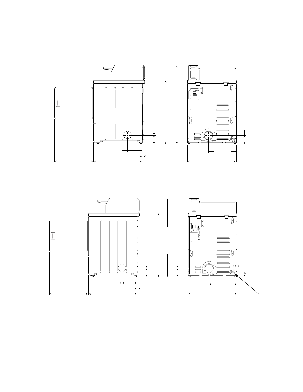
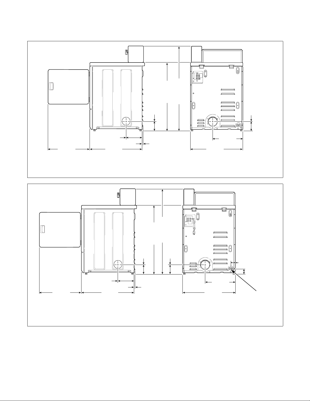
Roughing In Dimensions
Metered Models
Installation
*36" (91.4 cm)
4.5"
(11.4 cm)
43.2" (109.7 cm)
4.0"
(10.2 cm)
23.5"
(59.7 cm)
*With leveling legs turned into base.
23.5"
(59.7 cm)
*With leveling legs turned into base.
1 3/8" N.P.T. Gas Connection
8.0"
(20.3 cm)
8.0"
(20.3 cm)
(71.1 cm)
28"
(71.1 cm)
28"
0.4"
(1.02 cm)
ELECTRIC MODELS
*36" (91.4 cm)
4.5"
(11.4 cm)
(1.02 cm)
0.4"
43.2" (109.7 cm)
GAS MODELS
4.0"
(10.2 cm)
26.9"
(68.3 cm)
26.9"
(68.3 cm)
15.4"
(39.1 cm)
15.4"
(39.1 cm)
D611I
2.3"
(6 cm)
2.8"
(7 cm)
D611I
1
DRY22N
NOTE: Side, rear and bottom exhaust openings are
4 inch (10.2 cm) ducting. Gas models cannot be
vented out left side of cabinet because of burner
housing.
510969
© Copyright, Alliance Laundry Systems LLC – DO NOT COPY or TRANSMIT
IMPORTANT: The dryer should have sufficient
clearance around it for needed ventilation and for
the ease of installation and servicing. For maximum
drying performance, we recommend that more
clearance be allowed around the dryer than the
clearances that are listed throughout this manual.
9
Page 12
Installation
Nonmetered Models
4.5"
(11.4 cm)
*36" (91.4 cm)
43.2" (109.7 cm)
4.0"
(10.2 cm)
23.5"
(59.7 cm)
*With leveling legs turned into base.
8.0"
(20.3 cm)
23.5"
(59.7 cm)
(71.1 cm)
*With leveling legs turned into base.
1 3/8" N.P.T. Gas Connection
8.0"
(20.3 cm)
28"
(71.1 cm)
28"
0.4"
(1.02 cm)
ELECTRIC MODELS
43.2" (109.7 cm)
*36" (91.4 cm)
4.5"
(11.4 cm)
0.4"
(1.02 cm)
4.0"
(10.2 cm)
GAS MODELS
26.9"
(68.3 cm)
(39.1 cm)
26.9"
(68.3 cm)
(39.1 cm)
15.4"
15.4"
2.3"
(6 cm)
D613I
2.8"
(7 cm)
D613I
1
D614I
NOTE: Side, rear and bottom exhaust openings are
4 inch (10.2 cm) ducting. Gas models cannot be
vented out left side of cabinet because of burner
housing.
10
© Copyright, Alliance Laundry Systems LLC – DO NOT COPY or TRANSMIT© Copyright, Alliance Laundry Systems LLC – DO NOT COPY or TRANSMIT© Copyright, Alliance Laundry Systems LLC – DO NOT COPY or TRANSMIT© Copyright, Alliance Laundry Systems LLC – DO NOT COPY or TRANSMIT
IMPORTANT: The dryer should have sufficient
clearance around it for needed ventilation and for
the ease of installation and servicing. For
maximum drying performance, we recommend
that more clearance be allowed around the dryer
than the clearances that are listed throughout this
manual.
510969
Page 13
Installation
Meter Case
(Metered Models)
The factory mounted coin meter case does not include
the service door lock, coin drawer, coin drawer lock
and keys. These parts must be ordered (at extra cost)
according to the purchaser’s requirements direct from
the manufacturer of your choice.
NOTE: You have the option of using a screw type
lock or a 1/4 turn lock on the meter case service
door. If you choose to use a screw lock, then the
special bracket (located inside the meter case) must
be used. DO NOT use the special bracket if a
1/4 turn lock is used.
Coin Drawer Security – for additional security, drill
out the two pilot holes on each front side of the meter
case to 1/4 or 5/16 inch (6.4 or 8.0 mm) holes and
install a bicycle lock through these holes.
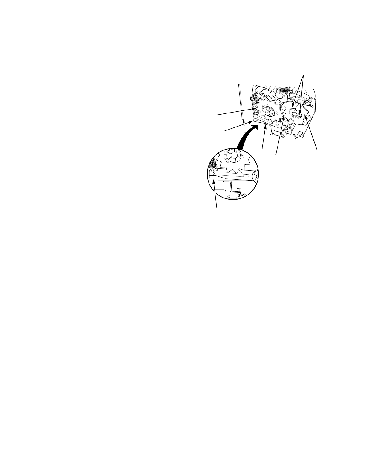
Timer Cams
(Coin Slide Models Only)
The dryer timer is factory equipped with a 45 minute
timing cam. If this drying time is not suitable to your
installation, the following cams can be found in the
envelope located in the cylinder.
ELECTRIC DRYERS
1-53242 Cam (30 Minutes)
1-53240 Cam (60 Minutes)
GAS DRYERS
NOTE: Adjust ratchet wheel and timing cam to
“OFF” position prior to putting dryer into use.
Refer to Figure 1 for proper position.
1
6
5
4
3
7
1 Retaining Prongs
2 Timing Cam
3 Notch
4 Levers
5 Off Position
6 Ratchet Wheel
7 On Position
2
D775I
D775I
1-53242 Cam (30 Minutes)
A 60 minute timing cam, Part No. 53240, is available
for the gas dryer as optional equipment at extra cost.
To change the timing cam:
1. Align notch in cam with a tooth on ratchet wheel.
2. Squeeze the ends of the two timing cam prongs
together.
3. Carefully lift timing cam off post.
510969
© Copyright, Alliance Laundry Systems LLC – DO NOT COPY or TRANSMIT
Figure 1
11
Page 14
Installation
To reduce the risk of electric shock, fire,
explosion, serious injury or death:
• Disconnect electric power to the
dryer(s) before servicing.
• Close gas shut-off valve to gas dryer(s)
before servicing.
• Never start the dryer(s) with any guards/
panels removed.
• Whenever ground wires are removed
during servicing, these ground wires
must be reconnected to ensure that the
dryer is properly grounded.
W001R1
WARNING
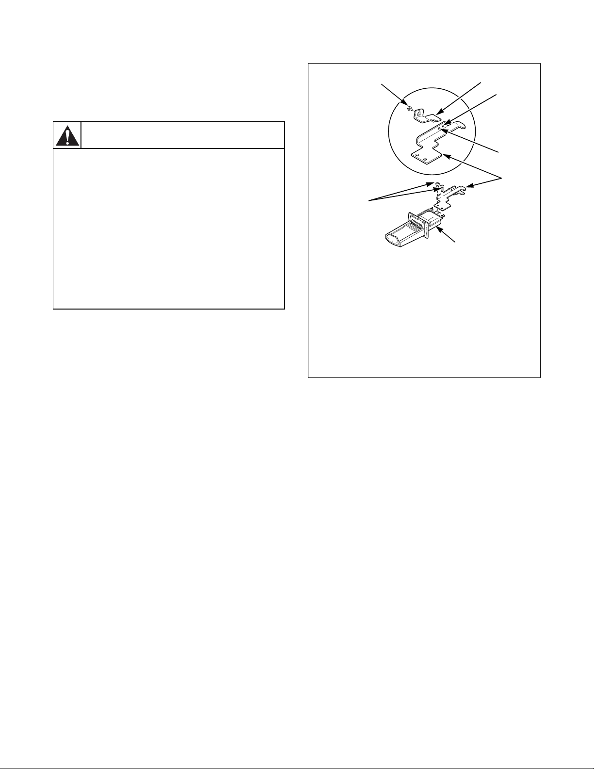
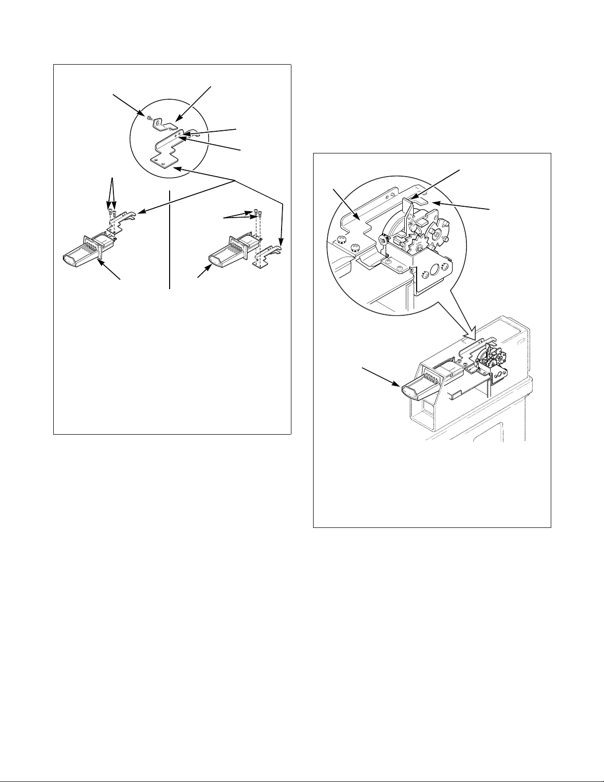
Dryer Slide Extension
(Coin Slide Models Only)
Short Vault Slide Extension
1. Assemble coin slide extension, No. 503733, to
top side of coin slide using two Phillips head
screws and lockwashers, No. 03950. Tighten
firmly. Refer to Figure 2.
2. Install slide extension modifier, No. 501796, as
follows:
NOTE: Dryers equipped with Greenwald coin
slides (except for Greenwald Comet Slide or
Greenwald Tokette Slide) do not require the use of
the slide extension modifier.
● ESD Coin Slide – Mount slide extension
modifier, No. 501796, to the underside of slide
extension, No. 503733. Align the hole in the slide
extension modifer with hole “A” in the slide
extension and install self-tapping screw, No.
501086. Tighten firmly. Refer to Figure 2.
● GREENWALD Comet Slide, GREENWALD
Tokette Slide or MONARCH Coin Slide –
Mount slide extension modifier, No. 501796, to
the underside of slide extension, No. 503733.
Align the hole in the slide extension modifier
with hole “B” in the slide extension and install
self-tapping screw, No. 501086. Tighten firmly.
Refer to Figure 2.
12
© Copyright, Alliance Laundry Systems LLC – DO NOT COPY or TRANSMIT© Copyright, Alliance Laundry Systems LLC – DO NOT COPY or TRANSMIT© Copyright, Alliance Laundry Systems LLC – DO NOT COPY or TRANSMIT© Copyright, Alliance Laundry Systems LLC – DO NOT COPY or TRANSMIT
1
7
1 501086 Self-Tapping Screw
2 501796 Slide Extension Modifier
3 Hole “A”
4 Hole “B”
5 503733 Slide Extension
6 Coin Slide
7 03950 Phillips Head Screws and
Lockwashers
Figure 2
2
3
4
5
6
3. Reinstall coin slide in dryer meter case.
4. CHECK DRYER OPERATION – Connect
electrical power to dryer. Place required number
of coins in coin slide. Push slide in, and observe
through service door opening in meter case. The
slide extension should be contacting the
accumulator actuator arm and moving back with
slide travel.
When slide is pushed all the way in, slide is
retracted. Accumulator actuator arm should
remain back until slide extension is moved
forward and contacts actuator arm again,
returning arm to starting position. Refer to
Figure 3.
D019K
510969
Page 15
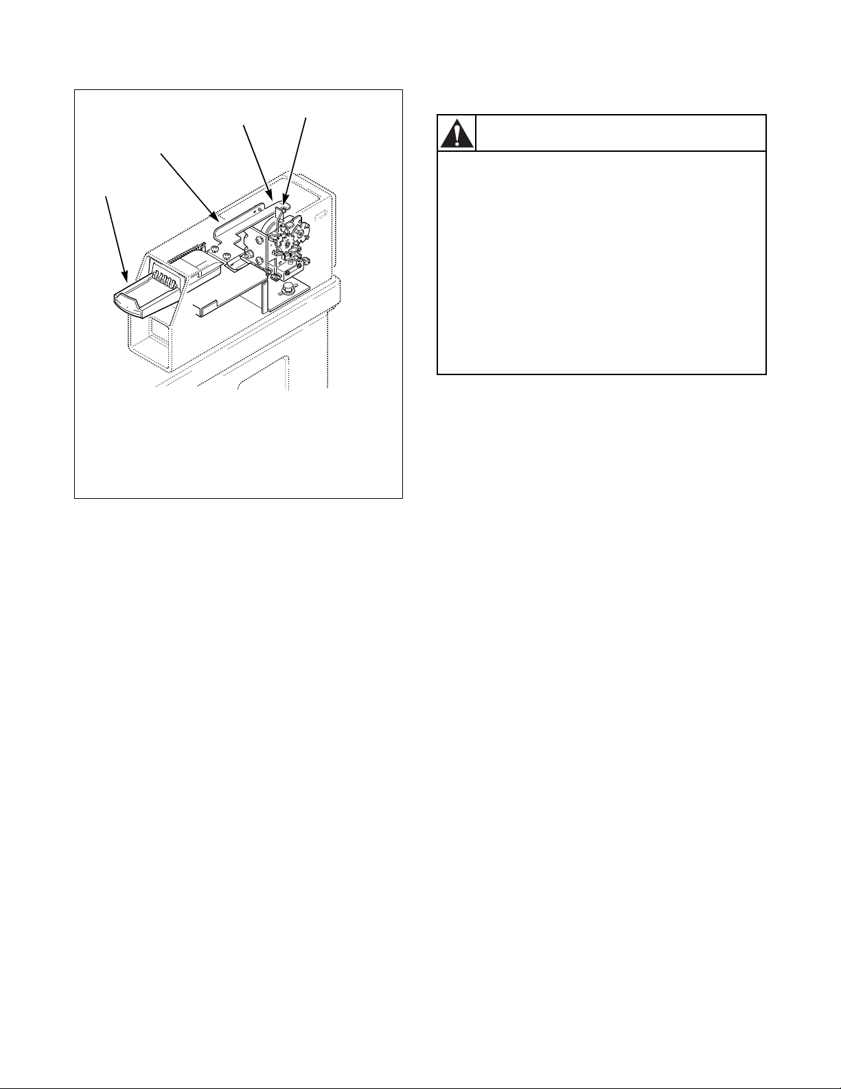
3
2
1
1 Coin Slide
2 Slide Extension
3 Accumulator Actuator Arm
4 Slide Extension Modifier
Figure 3
4
DRY1925N
5. After completing the dryer check, reinstall
service door on top of meter case.
NOTE: When reinstalling service door, front of
door must be inserted at about a 45° angle in order
to engage notched tabs with internal rib at top of
meter case.
Installation
Long Vault Slide Extension
WARNING
To reduce the risk of electric shock, fire,
explosion, serious injury or death:
• Disconnect electric power to the
dryer(s) before servicing.
• Close gas shut-off valve to gas dryer(s)
before servicing.
• Never start the dryer(s) with any guards/
panels removed.
• Whenever ground wires are removed
during servicing, these ground wires
must be reconnected to ensure that the
dryer is properly grounded.
W001R1
1. Remove the coin slide out through front of meter
case.
2. For Comet, Tokette and Monarch coin slides:
Assemble the slide extension, No. 506114, to the
top side of the coin slide using the two Phillips
head screws and lockwashers, No. 511419, and
tighten firmly. Refer to Figure 4.
For Greenwald and ESD coin slides:
Assemble the slide extension, No. 506114, to the
bottom side of the coin slide using the two Phillips
head screws and lockwashers, No. 511419, and
tighten firmly. Refer to Figure 4.
3. Install slide extension modifier, No. 501796, as
follows:
510969
NOTE: Dryers equipped with a Greenwald coin
slide (except for the Greenwald Comet Slide or the
Greenwald Tokette slide) do not require the use of
the slide extension modifier.
● ESD Coin Slide – Mount the slide extension
modifier, No. 501796, to the underside of the
slide extension, No. 506114. Align the hole in the
slide extension modifier with hole “A” in the
slide extension and install the self-tapping screw,
No. 501086, and tighten firmly. Refer to
Figure 4.
● GREENWALD Comet Slide, GREENWALD
Tokette Slide or MONARCH Coin Slide –
Mount the slide extension modifier, No. 501796,
to the underside of the slide extension,
No. 506114. Align the hole in the slide extension
modifier with hole “B” in the slide extension and
install the self-tapping screw, No. 501086, and
tighten firmly. Refer to Figure 4.
© Copyright, Alliance Laundry Systems LLC – DO NOT COPY or TRANSMIT
13
Page 16
Installation
2
1
3
4
5
5
6
6
7
COMET, TOKETTE AND
MONARCH COIN SLIDES
GREENWALD AND
ESD COIN SLIDES
1 501796 Slide Extension Modifier
2 Hole “A”
3 Hole “B”
4 506114 Slide Extension
5 03950 Phillips Head Screws and
Lockwashers
6 Coin Slide
7 501086 Self-Tapping Screw
6. After completing the dryer check, reinstall
service door on top of meter case.
NOTE: When reinstalling service door, front of
door must be inserted at about a 45° angle in order
to engage notched tabs with internal rib at top of
meter case.
1
4
2
DRY1967K
DRY1967K
3
Figure 4
4. Reinstall coin slide in dryer meter case. Refer to
Figure 5.
NOTE: The position of the accumulator arm is
between the push and pull extension of the slide
extension.
5. CHECK DRYER OPERATION – Connect
electrical power to dryer. Place required number
of coins in coin slide. Push slide in and observe
through service door opening in meter case if the
slide extension is contacting the accumulator
actuator arm and moving arm back with slide
travel.
When slide is pushed all the way in (accumulator
arm will be rotated to the back) and slide is
retracted, the accumulator actuator arm should
remain back until the slide extension is moved
forward and again contacts the actuator arm to
return the arm to the starting forward position.
Refer to Figure 5.
DRY1968K
1 Accumulator Actuator Arm
2 501796 Slide Extension Modifier
(If required)
3 Coin Slide
4 506114 Slide Extension
Figure 5
14
© Copyright, Alliance Laundry Systems LLC – DO NOT COPY or TRANSMIT© Copyright, Alliance Laundry Systems LLC – DO NOT COPY or TRANSMIT© Copyright, Alliance Laundry Systems LLC – DO NOT COPY or TRANSMIT© Copyright, Alliance Laundry Systems LLC – DO NOT COPY or TRANSMIT
510969
Page 17
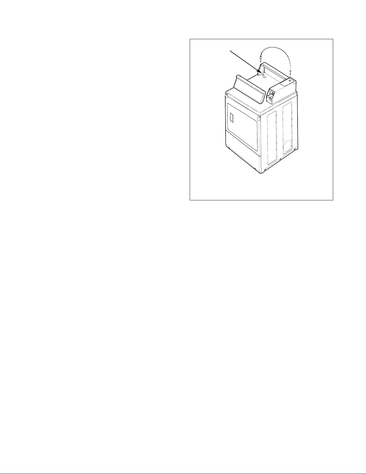
Additional Dryer Security
Located on the service door of the dryer is a flat
Phillips head screw. During shipment, this screw is
used to attach the service door to the meter case. For
additional security, this screw can be reinstalled inside
the control hood of your dryer. Following is the
procedure for installing this screw:
1. Remove the Phillips head screw from service
door. (Refer to Figure 6.)
2. Remove two screws holding control panel to
control hood.
3. Tilt control panel forward and lay on a protective
pad to prevent scratching of cabinet top.
4. Insert Phillips head screw down through double
“D” hole in left rear corner of cabinet top (inside
control hood) until it engages retainer nut located
on left rear corner gusset of cabinet.
5. Finger tighten screw.
IMPORTANT: Do not use a power driver to
tighten screw. Torque of a power driver could overtighten screw causing damage to cabinet assembly.
Installation
1
D687I
D687I
1 Double “D” Hole
Figure 6
510969
© Copyright, Alliance Laundry Systems LLC – DO NOT COPY or TRANSMIT
15
Page 18
Installation
1 2
3
4
5
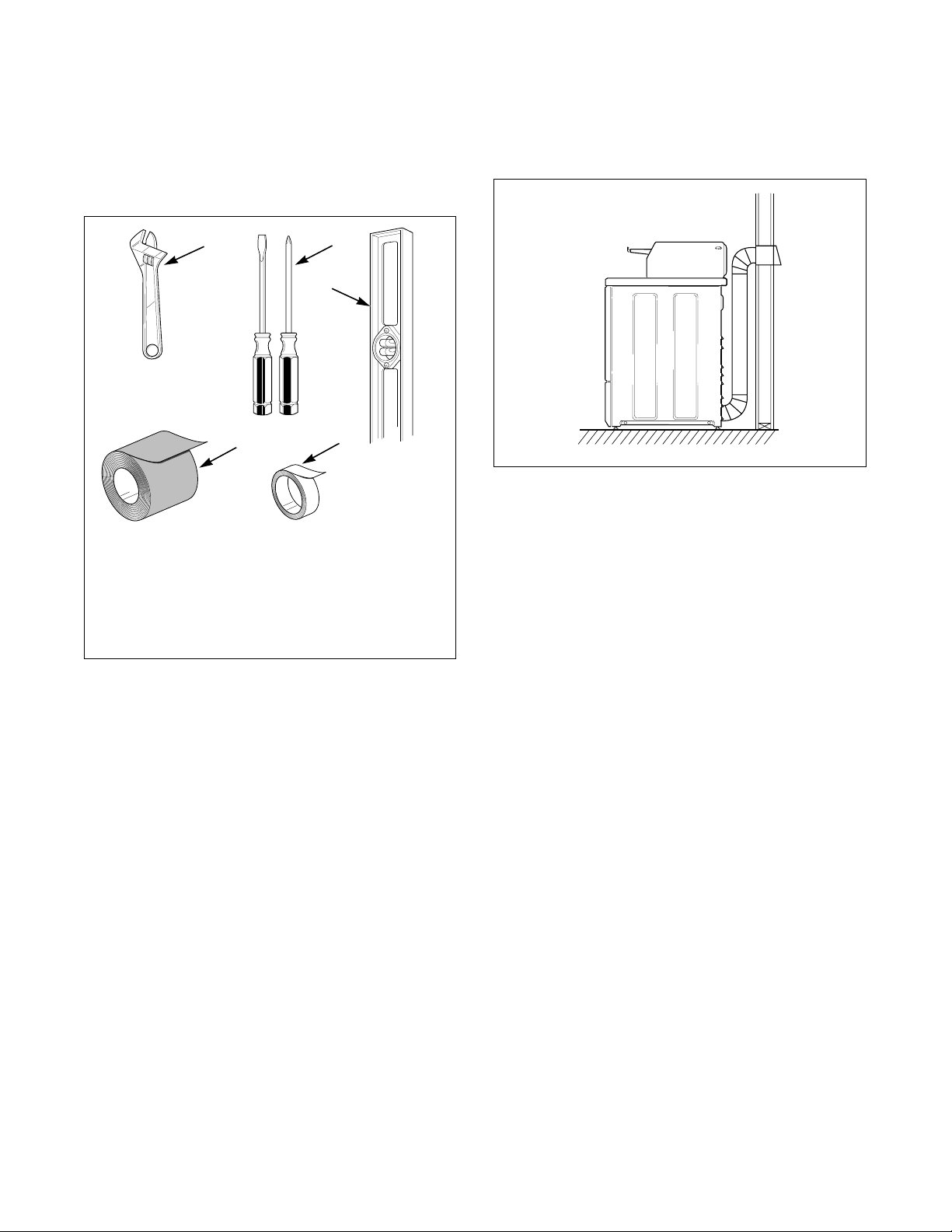
Before You Start
Tools
For most installations, the basic tools you will need
are:
D818I
1 Wrench
2 Screwdrivers
3 Level
4 Te f l on Ta pe
5 Duct Tape
Figure 7
Gas
Dryer is equipped for Natural Gas with a 3/8" N.P.T.
gas supply connection. For more detailed information,
refer to section on Gas Requirements.
Location
Exhaust
Use rigid metal duct and exhaust the dryer to the
outside by the shortest route possible.
D333I
Figure 8
NOTE: For more detailed information, refer to
section on Dryer Exhaust Requirements.
Electrical
● ELECTRIC DRYER
Dryer needs a 3 or 4 wire 120/240 or 120/208
Volt, 60 Hertz, 30 Amp, AC single Phase
electrical supply.
● GAS DRYER
Dryer needs a 120 Volt, 60 Hertz, 15 Amp,
polarized 3-slot effectively grounded receptacle.
NOTE: For more detailed information, refer to
section on Electrical Requirements.
❂
Place the dryer on a solid floor with an adequate air
supply. For more detailed information, refer to section
on Location Requirements.
16
© Copyright, Alliance Laundry Systems LLC – DO NOT COPY or TRANSMIT© Copyright, Alliance Laundry Systems LLC – DO NOT COPY or TRANSMIT© Copyright, Alliance Laundry Systems LLC – DO NOT COPY or TRANSMIT© Copyright, Alliance Laundry Systems LLC – DO NOT COPY or TRANSMIT
510969
Page 19
Installation
2
1
3
4
Installing the Dryer
Step 1: Position and Level the Dryer
For further assistance refer to section on Location
Requirements.
Install dryer before washer. This allows room for
attaching exhaust duct.
Install the four rubber cups found in the accessory bag.
Place the dryer in position, and adjust the legs until the
dryer is level from side to side and front to back.
Step 2: Connect Dryer Exhaust System
For further assistance refer to sections on Location
Requirements and Dryer Exhaust Requirements.
WARNING
A clothes dryer produces combustible lint.
To reduce the risk of fire and combustion
gas accumulation the dryer MUST be
exhausted to the outdoors.
W116
● DO NOT use plastic or thin foil ducting.
● Locate dryer so exhaust duct is as short as
possible.
● Be certain old ducts are cleaned before installing
your new dryer.
● Use 4" (10.2 cm) diameter rigid or flexible metal
duct.
● The male end of each section of duct must point
away from the dryer.
● Use as few elbows as possible.
● Use duct tape or pop-rivets on all duct joints.
● Ductwork that runs through unheated areas must
D678I
D678I
1 Dryer Base
2 Level
3 Leveling Leg
4 Rubber Cup
be insulated to help reduce condensation and lint
build-up on pipe walls.
● Install backdraft dampers in multi-dryer
installations.
● Failure to exhaust dryer properly will void
warranty.
Figure 9
DO DON’T
D333I
D333I D335I
Figure 10
D335I
NOTE: Venting materials are not supplied with the
dryer (obtain locally).
510969
© Copyright, Alliance Laundry Systems LLC – DO NOT COPY or TRANSMIT
17
Page 20
Installation
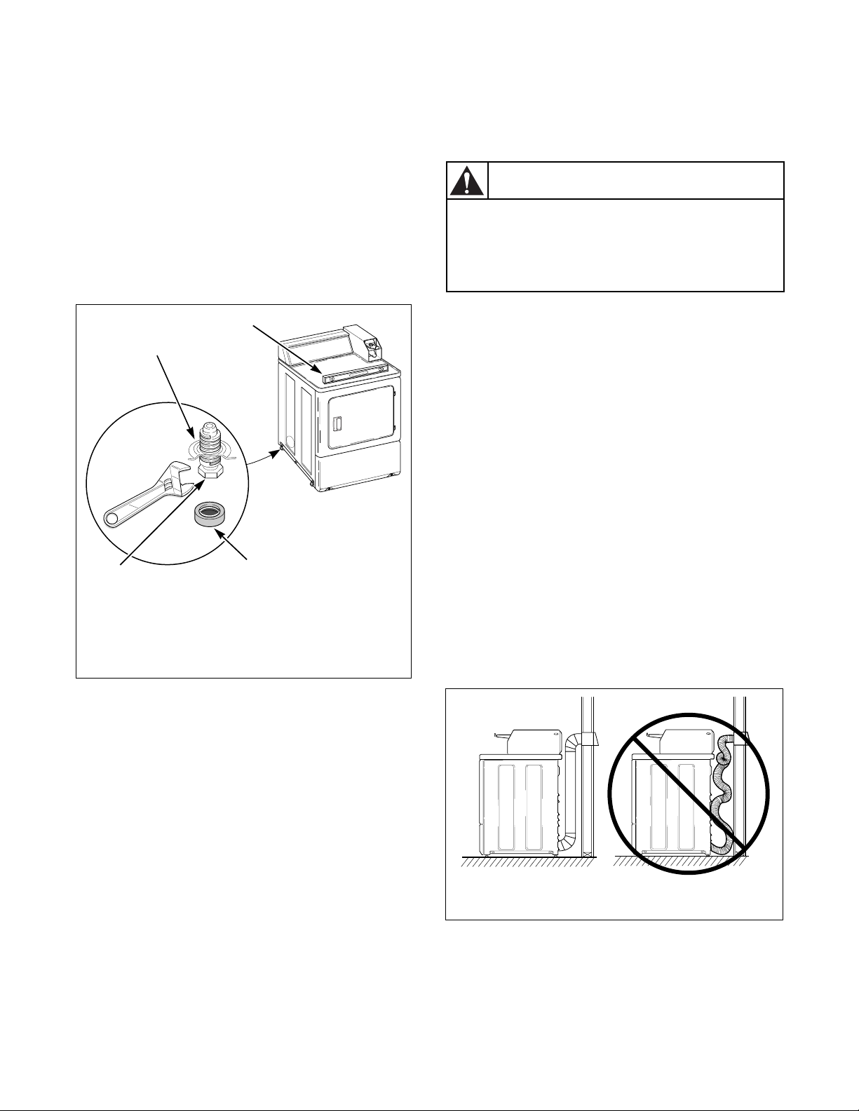
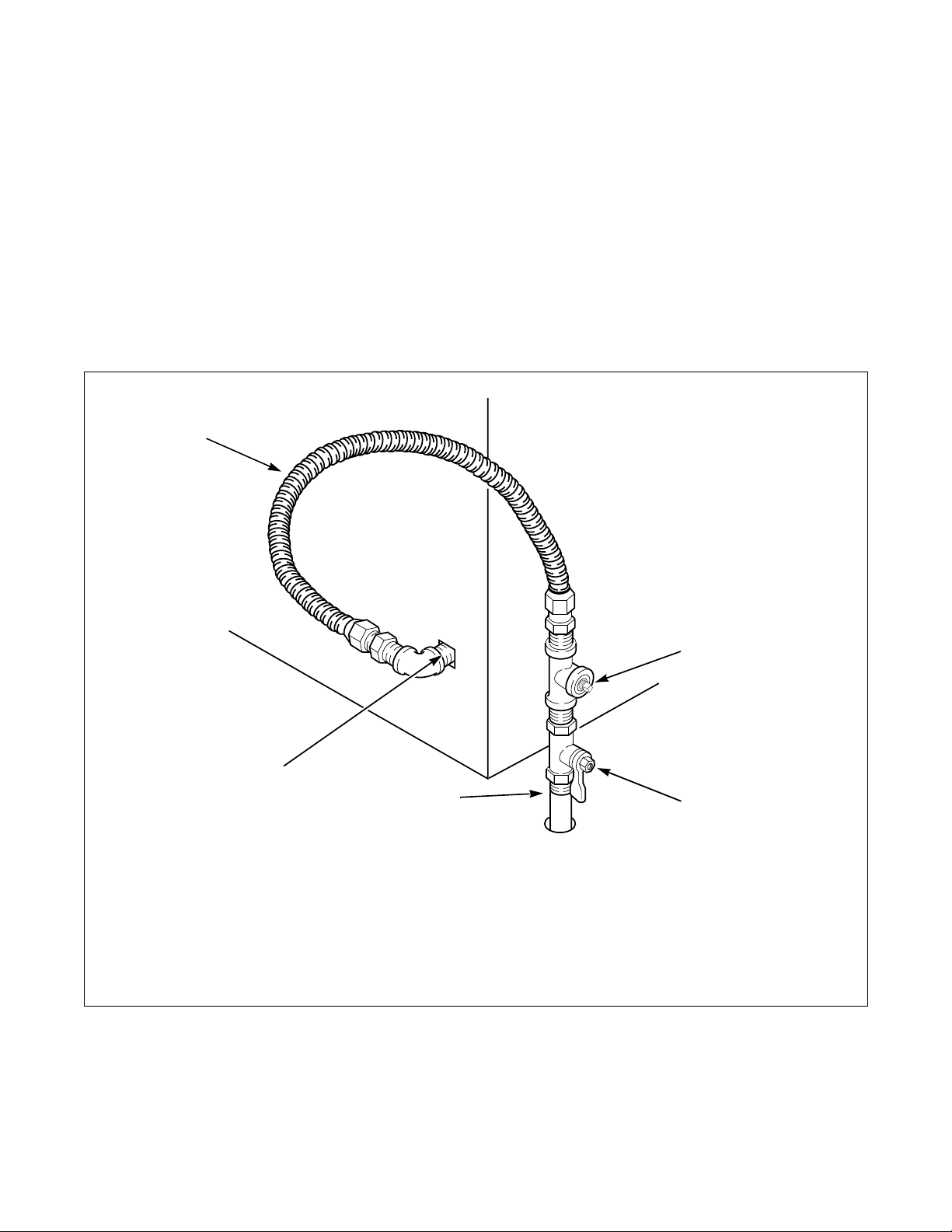
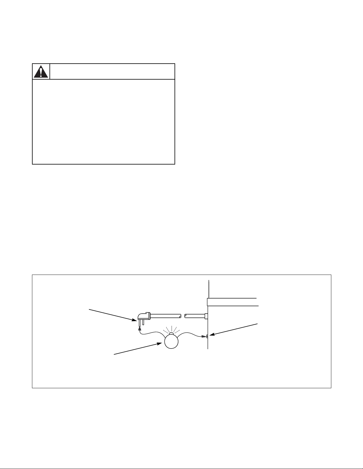
Step 3: (Gas Dryer Only) Connect Gas
Supply Pipe
For further assistance, refer to section on Gas
Requirements.
1. Make certain dryer is equipped for use with the
type of gas in laundry room. Dryer is equipped at
the factory for Natural Gas with a 3/8" N.P.T.
gas connection.
2. Remove the shipping cap from the gas
connection at the rear of the dryer. Make sure
you do not damage the pipe threads when
removing the cap.
1
3. Connect to gas supply pipe.
4. Tighten all connections securely. Turn on gas
and check all pipe connections (internal &
external) for gas leaks with a non-corrosive leak
detection fluid.
5. For L.P. (Liquefied Petroleum) gas connection,
refer to section on Gas Requirements.
5
4
1 New Stainless Steel Flexible Connector –
Use only if allowed by local codes
(Use Design A.G.A. Certified Connector)
2 1/8" N.P.T. Pipe Plug
(For checking inlet gas pressure)
3 Equipment Shut-Off Valve – Installed within 6'
(1.8 m) of dryer
Figure 11
2
3
D233I
D233I
4 Black Iron Pipe
Shorter than 20' (6.1 m) – Use 3/8" pipe
Longer than 20' (6.1 m) – Use 1/2" pipe
5 3/8" N.P.T. Gas Connection
18
© Copyright, Alliance Laundry Systems LLC – DO NOT COPY or TRANSMIT© Copyright, Alliance Laundry Systems LLC – DO NOT COPY or TRANSMIT© Copyright, Alliance Laundry Systems LLC – DO NOT COPY or TRANSMIT© Copyright, Alliance Laundry Systems LLC – DO NOT COPY or TRANSMIT
510969
Page 21
Step 4: (Electric Dryer Only) Connect
1
2
3
4
FOUR-WIRE
Electrical Plug
Installation
1
2
For further assistance, refer to section on Electrical
Requirements.
IMPORTANT: Use only a new U.L. listed No. 10
(copper wire only) three conductor power supply
cord kit rated 240 Volts (minimum) 30 Amperes
and labeled as suitable for use in a clothes dryer.
1
4
THREE-WIRE
2
3
D275I
8
7
THREE-WIRE CONNECTION
8
1
7
1
3
4
5
6
D679I
D679I
3
4
9
10
11
D006I
1 Typical Receptacle
2 Power Cord
3 Strain Relief Nut
4 Strain Relief
Figure 12
NOTE: For more detailed information on
connecting three-wire or four-wire plugs, refer to
section on Electrical Connection.
NOTE: Four-wire cord is required for mobile
homes or where codes do not permit grounding
through neutral.
NOTE: Dryer is shown with access cover removed for
illustration purposes only. NEVER operate the dryer
with access cover removed.
1 Ground Wire
2 Ground to Neutral Wire
3 Neutral Terminal
4 “L2” Terminal
5 Center Wire (Neutral)
6 Strain Relief (Not supplied with dryer)
7 Ground Screw
8 “L1” Terminal
9 Black Wire
10 White Wire (Neutral)
11 Red Wire
FOUR-WIRE CONNECTION
Figure 13
6
D680I
D680I
510969
© Copyright, Alliance Laundry Systems LLC – DO NOT COPY or TRANSMIT
19
Page 22
Installation
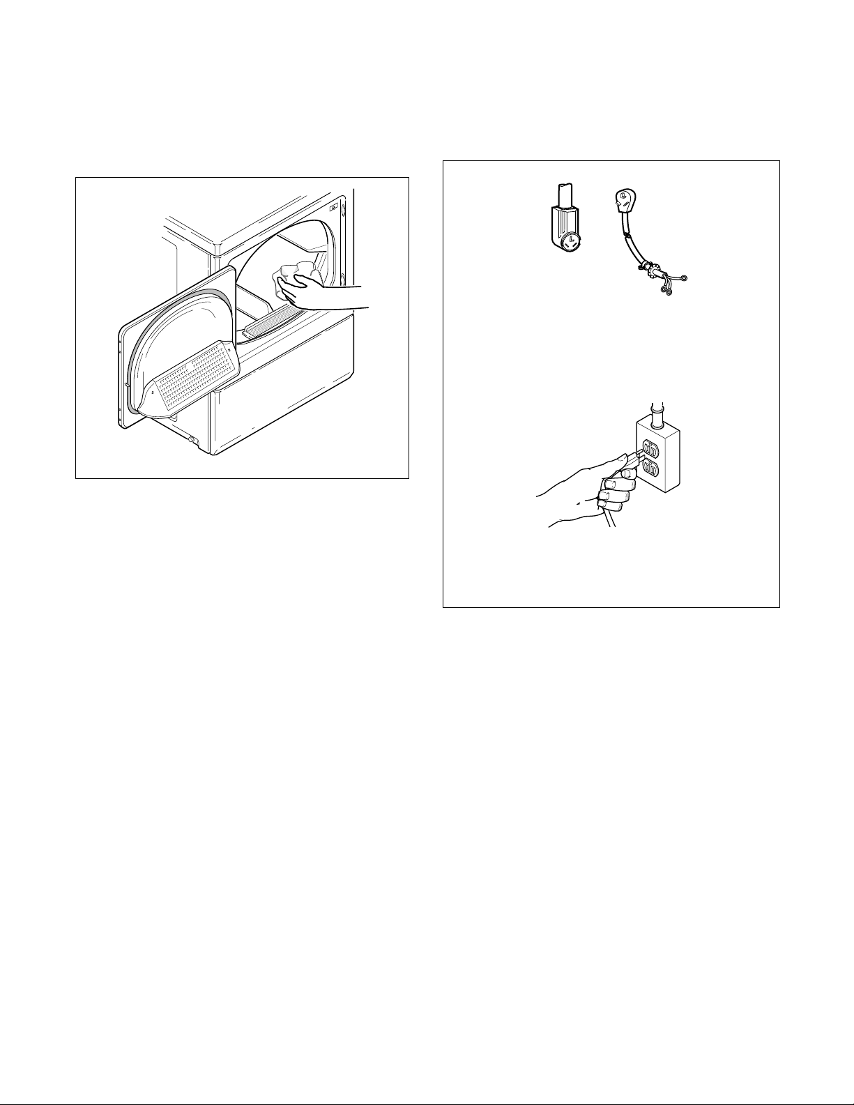
Step 5: Wipe Out Inside of Dryer
Before using dryer for the first time, use an all-purpose
cleaner, or a detergent and water solution, and a damp
cloth to remove shipping dust from inside dryer drum.
D604I
D604I
Figure 14
Step 6: Plug In the Dryer
Refer to section on Electrical Requirements, and
connect the dryer to an electrical power source.
ELECTRIC
Connect to 30 Amp circuit.
D275I
D254I
GAS
Plug cord into separately fused 15 Amp circuit.
D254I
Figure 15
Step 7: Check Installation
Refer to Installer Checklist on back cover and make
sure that dryer is installed correctly.
20
© Copyright, Alliance Laundry Systems LLC – DO NOT COPY or TRANSMIT© Copyright, Alliance Laundry Systems LLC – DO NOT COPY or TRANSMIT© Copyright, Alliance Laundry Systems LLC – DO NOT COPY or TRANSMIT© Copyright, Alliance Laundry Systems LLC – DO NOT COPY or TRANSMIT
510969
Page 23

Installation
Heat Source Check
Electric Dryers
Metered Models
Set the proper FABRIC SELECTOR switch at
NORMAL. Place coins in the slide and carefully push
slide in as far as possible. IN USE light will come on
indicating the dryer is ready to operate. Close the
loading door and press the PUSH-TO-START button
firmly to start the dryer. After the dryer has operated
for three minutes, the exhaust air or exhaust pipe
should be warm.
Nonmetered Models
Set FABRIC SELECTOR switch at NORMAL and
turn timer knob to 50. Close the loading door and press
the PUSH-TO-START button. IN USE light will
come on indicating start of cycle. After the dryer has
operated for three minutes, the exhaust air or exhaust
pipe should be warm.
Gas Dryers
During the gas heat check, observe the burner flame.
The flame can be viewed by removing the lower front
panel of the dryer.
Metered Models
Set FABRIC SELECTOR switch at NORMAL. Place
coins in the slide and carefully push slide in as far as
possible. IN USE light will come on indicating the
dryer is ready to operate. Close the loading door and
press the PUSH-TO-START button firmly. The dryer
will start, the igniter will glow red and the main burner
will ignite.
Nonmetered Models
Set FABRIC SELECTOR switch at NORMAL and
turn timer knob to 50. Close the loading door and press
the PUSH-TO-START button. IN USE light will
come on indicating start of cycle, igniter will glow red
and main burner will ignite.
IMPORTANT: If all air is not purged out of the
gas line, the gas igniter may go off before the gas is
ignited. If this happens, after approximately two
minutes the igniter will again attempt gas ignition.
510969
© Copyright, Alliance Laundry Systems LLC – DO NOT COPY or TRANSMIT
21
Page 24
Installation
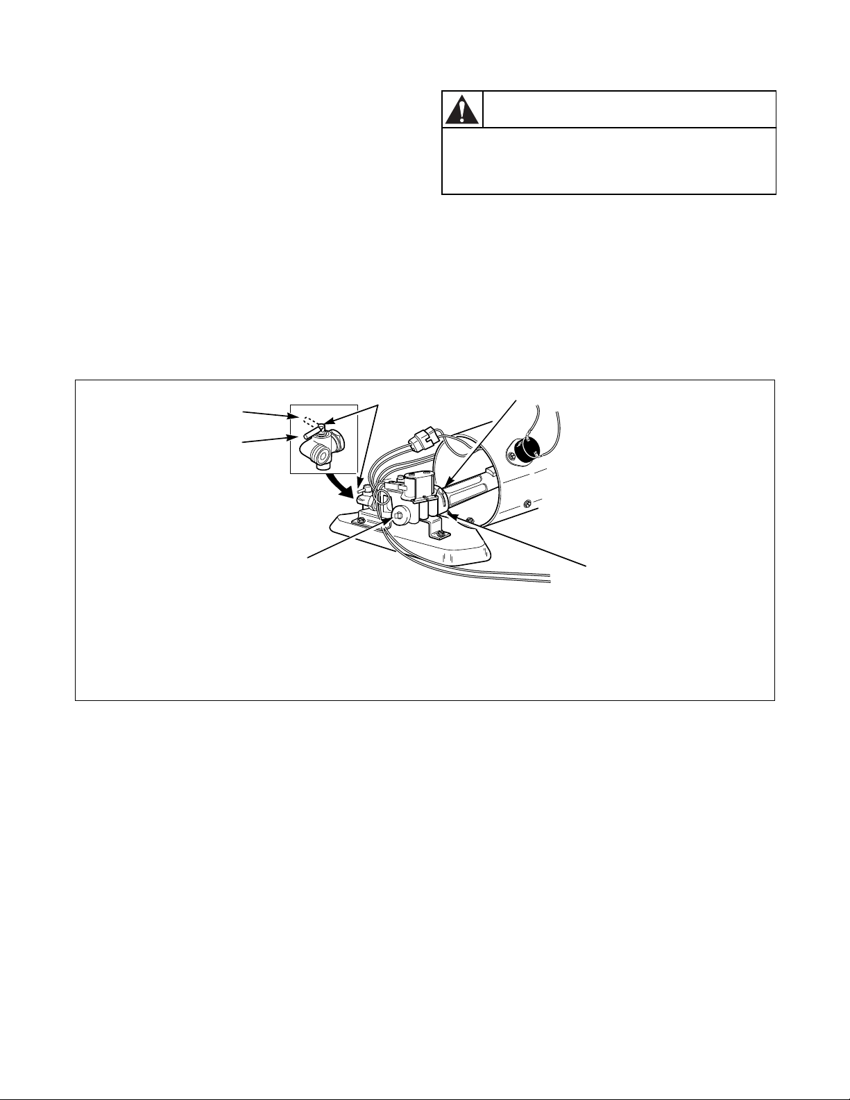
All Models
After the dryer has operated for approximately five
minutes, observe burner flame. Adjust the air shutter
to obtain a soft, uniform blue flame. (A lazy, yellowtipped flame indicates lack of air. A harsh, roaring,
very blue flame indicates too much air.) Adjust the air
shutter as follows:
1. Loosen the air shutter lockscrew.
2. Turn the air shutter to the left to get a luminous
yellow tipped flame, then turn it back slowly to
the right to obtain a steady soft blue flame.
3. After the air shutter is adjusted for proper flame,
tighten the air shutter lockscrew securely.
4. Reinstall the lower front panel.
WARNING
For personal safety, lower front panel must
be in place during normal operation.
W046
After the dryer has operated for approximately three
minutes, the exhaust air or exhaust pipe should be
warm.
1
6
5
1 Closed Position 5 1/8" (3.1 mm) Pipe Plug
2 Shut-Off Valve Handle
3 Air Shutter Lockscrew 6 Open Position
4 Air Shutter
2
Figure 16
3
4
(For checking manifold pressure)
D700I
22
© Copyright, Alliance Laundry Systems LLC – DO NOT COPY or TRANSMIT© Copyright, Alliance Laundry Systems LLC – DO NOT COPY or TRANSMIT© Copyright, Alliance Laundry Systems LLC – DO NOT COPY or TRANSMIT© Copyright, Alliance Laundry Systems LLC – DO NOT COPY or TRANSMIT
510969
Page 25
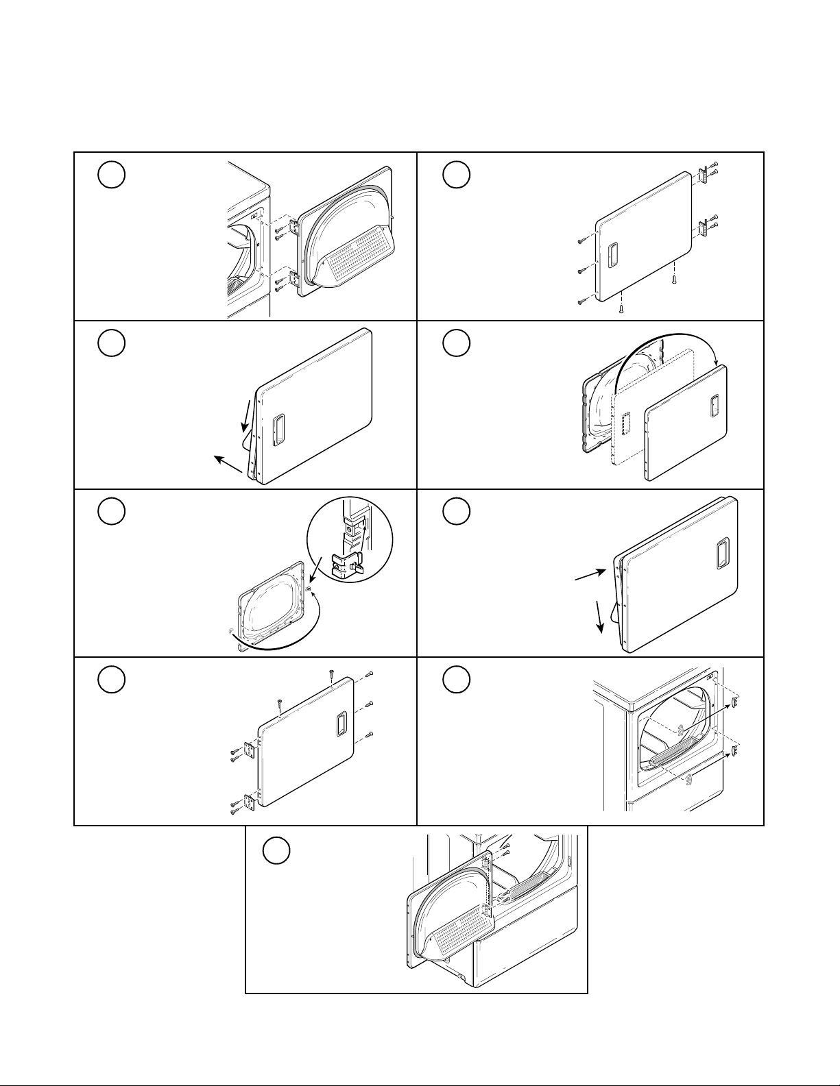
Reversing Door Procedure
1
Remove four hinge
attaching screws.
D310S
B
A
D312S
3
Pull bottom of door
liner out, then pull
down, removing
door liner from
door panel.
D312S
D314S
5
Remove door strike
from door liner and
reinstall on
opposite side.
D314S
D316S
7
Reinstall nine
screws removed in
step 2.
D316S
The door on this dryer is completely reversible.
To reverse door proceed as follows:
D675I
2
Remove all nine
screws.
4
Rotate door panel
180 degrees as
shown.
Installation
D311S
D311S
D313S
D313S
6
Insert liner under
flange on bottom of
B
door, then push top
of door liner into
place.
A
D315S
D315S
8
Using a screwdriver,
remove two door
plugs, and reinstall on
opposite side of door
opening.
D317S
D317S
9
510969
Reinstall four hinge
attaching screws
removed in step 1.
D606I
D606I
© Copyright, Alliance Laundry Systems LLC – DO NOT COPY or TRANSMIT
23
Page 26
Installation
To reduce the risk of fire and combustion
gas accumulation, the dryer MUST BE
EXHAUSTED TO THE OUTDOORS. Refer to
Section on Dryer Exhaust Requirements.
W047
WARNING
Manufactured (Mobile) Home
Installation
IMPORTANT: Installation must conform to
the Manufactured Home Construction and
Safety Standards, Title 24 CFR, Part 32-80 or
Standard CAN/CSA-Z240 MH.
The dryer can be installed in a manufactured (mobile)
home by following these instructions:
1. IMPORTANT: Gas dryers MUST be
permanently attached to the floor at the time
of installation. Order No. 526P3 Dryer
Installation Kit for a manufactured (mobile)
home installation. Follow the instructions
supplied with the kit.
2. Electrical Connections (Electric Dryer Only)
must be a 4-wire connection. (Refer to page 29.)
3. Venting – Dryer MUST be exhausted to the
outdoors.
● The dryer can be exhausted to the outdoors
through the back, left, right or bottom panel. Gas
dryers cannot be exhausted out the left side
because of the burner housing.
● Exhaust duct must not be connected to any other
duct, vent or chimney.
● Dryer exhaust duct MUST NOT terminate under
the mobile home.
● For proper operation, it is important that the dryer
has an ample amount of outside make-up air. The
free area of any opening for the introduction of
outside air must be at least 25 in
● When exhausting the dryer to the outdoors, the
2
(163 cm2).
dryer can be installed with “0” inch clearance at
the sides and rear. Clearance of the duct from
combustible construction must be a minimum of
2 inches (5.08 cm).
● Venting materials are not supplied with the dryer
(obtain locally).
WARNING
To reduce the risk of fire, the exhaust duct
and weather hood MUST be fabricated of a
material that will not support combustion.
Rigid or flexible metal pipe is
recommended for a clothes dryer.
W048
● The dryer exhaust duct must be secured to the
mobile home structure.
● Exhaust ducts MUST NOT be connected with
sheet metal screws or fasteners which extend into
the duct.
24
© Copyright, Alliance Laundry Systems LLC – DO NOT COPY or TRANSMIT© Copyright, Alliance Laundry Systems LLC – DO NOT COPY or TRANSMIT© Copyright, Alliance Laundry Systems LLC – DO NOT COPY or TRANSMIT© Copyright, Alliance Laundry Systems LLC – DO NOT COPY or TRANSMIT
510969
Page 27
Installation
To reduce the risk of fire, electric shock or
personal injury, all wiring and grounding
MUST conform with the latest edition of
the National Electrical Code ANSI/NFPA 70
or the Canadian Electrical Code, CSA
C22.1, and such local regulations as might
apply. It is the customer’s responsibility to
have the wiring and fuses checked by a
qualified electrician to make sure the
laundry room has adequate electrical
power to operate the dryer.
W035
WARNING
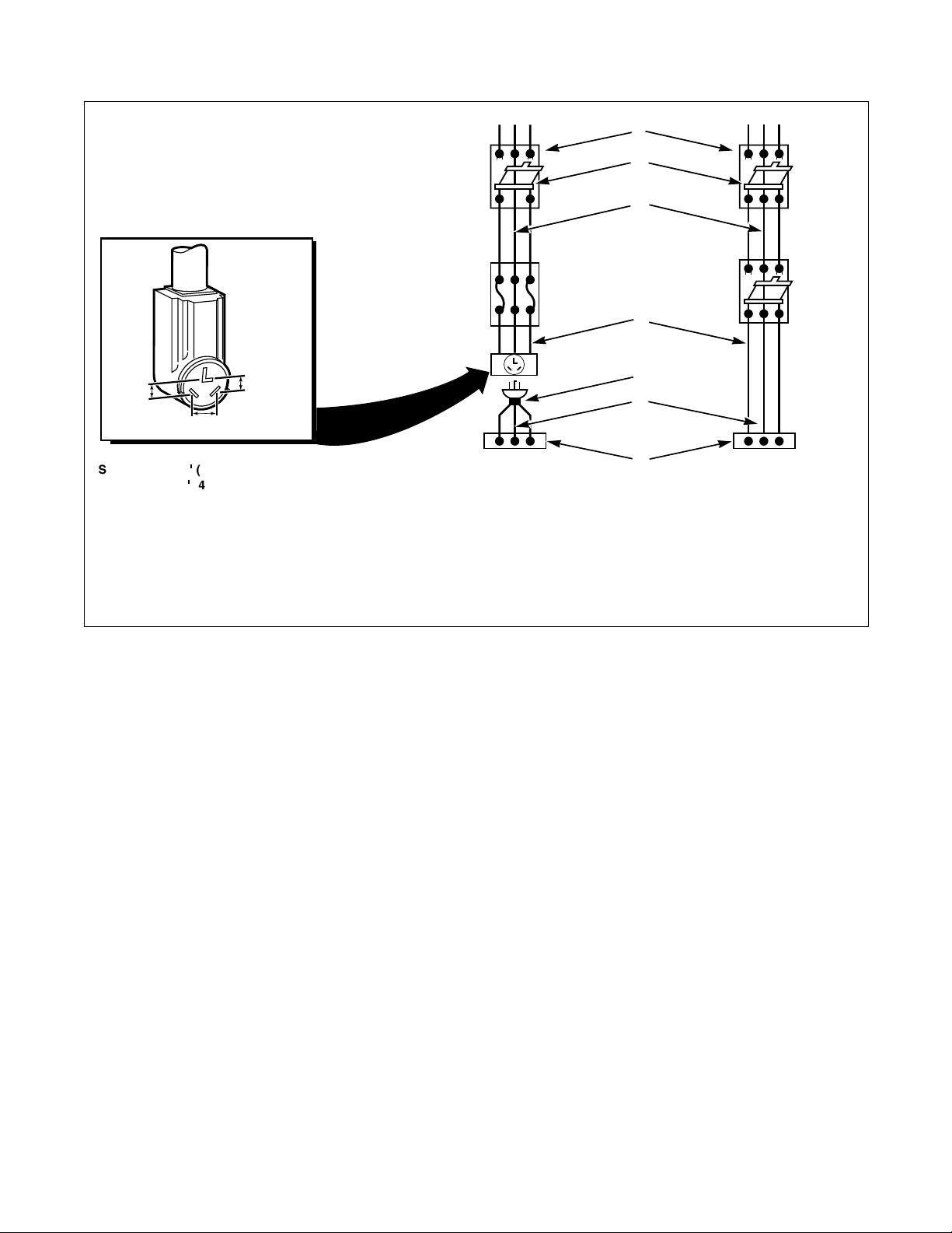
Electrical Requirements
Electric Dryers
(120/240 Volt, 60 Hertz, 3-Wire Installation)
(120/208 Volt, 60 Hertz, 3-Wire Installation)
NOTE: The wiring diagram is located inside the
control hood.
Grounding and Wiring Instructions
● The dryer must be connected to a grounded
metal, permanent wiring system; or an
equipment-grounding conductor must be run
with the circuit conductors and connected to the
equipment-grounding terminal or lead on the
dryer.
● The dryer has its own terminal block that must be
connected to a separate branch, 60 Hertz, single
phase circuit, AC (alternating current) circuit,
fused at 30 Amperes (the circuit must be fused
on both sides of the line). ELECTRICAL
SERVICE FOR THE DRYER SHOULD BE
OF MAXIMUM RATED VOLTAGE LISTED
ON THE NAMEPLATE. DO NOT
CONNECT DRYER TO 110, 115, OR
120 VOLT CIRCUIT. Heating elements are
available for field installation in dryers which are
to be connected to electrical service of different
voltage than that listed on nameplate, such as
208 Volt.
● If branch circuit to dryer is 15 feet (4.50 m) or
less in length, use U.L. (Underwriters
Laboratories) listed No. 10 A.W.G. wire (copper
wire only), or as required by local codes. If over
15 feet (4.50 m), use U.L. (Underwriters
Laboratories) listed No. 8 A.W.G. wire (copper
wire only), or as required by local codes. Allow
sufficient slack in wiring so dryer can be moved
from its normal location when necessary.
● The power cord (pigtail) connection between
wall receptacle and dryer terminal block IS NOT
supplied with dryer. Type of pigtail and gauge
of wire must conform to local codes and with
instructions mentioned on the following pages.
● The method of wiring the dryer is optional and
subject to local code requirements. Refer to
Figure 17.
510969
© Copyright, Alliance Laundry Systems LLC – DO NOT COPY or TRANSMIT
25
Page 28
Installation
E
NOTE: The power cord (pigtail) is NOT supplied with the electric
POWER SUPPLY POWER SUPPLY
dryer. Type of pigtail and gauge of wire must conform to local
codes and instructions.
The method of wiring the dryer is optional and subject to local
code requirements.
NOTE: Connect the dryer to the power supply with the
MAXIMUM RATED VOLTAGE listed on the nameplate.
A typical
30-Amp
Three-wire
Receptacle
NEMA Type
10-30R
120 ± 12
V.A.C.
240 ± 12
V.A.C.
NOTE: Use COPPER WIRE only.
120 ± 12
V.A.C.
k
Shorter than 15k (4.5 m) use 10 A.W.G.
k
Longer than 15
(4.5 m) use 8 A.W.G.
1 3-Wire Grounded Neutral 120/240 Volt, 60 Hertz
AC 1 Phase Service Entrance Switch Box
(See NOTE above)
INTERMEDIATE
FUSE BOX (May
be omitted if
service entrance
box is fused)
WALL RECEPTACLE
PIGTAIL CONNECTION
L1 L2 L1 L2
4 Metallic or Non-Metallic Sheathed Cable
(Copper wire only)
5 Pigtail to Dryer (See NOTE above)
2 30 Ampere Fuses or Circuit Breaker 6 Neutral
3 Neutral Wire 7 Terminal Block in Dryer
1
2
3
INTERMEDIAT
SHUT-OFF
(May be
omitted if
service
entrance box is
4
fused)
5
6
7
DIRECT CONNECTION
D816I
Figure 17
26
© Copyright, Alliance Laundry Systems LLC – DO NOT COPY or TRANSMIT© Copyright, Alliance Laundry Systems LLC – DO NOT COPY or TRANSMIT© Copyright, Alliance Laundry Systems LLC – DO NOT COPY or TRANSMIT© Copyright, Alliance Laundry Systems LLC – DO NOT COPY or TRANSMIT
510969
Page 29
Installation
The dryer is grounded to neutral conductor
at the terminal block. If the dryer is installed
in a mobile home, or if local codes do not
permit grounding through the neutral,
proceed as shown on Four-Wire Power
Cord instructions.
W134
To reduce the risk of electric shock,
disconnect the electrical service to the
dryer before proceeding.
W135
WARNING
Electrical Connection
Three-Wire Power Cord
1. Remove the screw and terminal block access
cover from the rear of the dryer cabinet.
2. Insert ends of direct wire through power supply
hole (containing proper strain relief) in rear of
dryer cabinet. Refer to Figure 19. Connect the
power cord, or direct wiring, to the appropriate
terminal block terminals using the three wire-
binding (10-32 x 3/8") screws from the
accessories pack in the envelope shipped inside
the dryer cylinder. If the dryer had previously
been connected with a four-wire power cord,
remove the four-wire power cord by reversing
procedures under Four-Wire Power Cord
instructions.
IMPORTANT: Use only a U.L. listed No. 10 A.W.G.
(copper wire only) three conductor power supply
cord kit rated 240 Volts (minimum)
30 Amperes and labeled as suitable for use in a
clothes dryer.
3. Tighten these wire-binding screws firmly.
IMPORTANT: Failure to tighten these screws
firmly may result in wire failure at the terminal
block.
4. Secure the strain relief to the power cord, or
wires, where they enter the dryer cabinet.
5. Check the continuity of the ground connection
before plugging the cord into an outlet. Use an
acceptable indicating device connected to the
center grounding pin of the plug and the green
screw on the back of the cabinet.
6. Reinstall access cover and screw.
1
3
1 Grounding Pin 3 Indicating Device (Must show continuity)
2 Ground Screw on Back of Cabinet
510969
© Copyright, Alliance Laundry Systems LLC – DO NOT COPY or TRANSMIT
2
D607I
D607I
Figure 18
27
Page 30
Installation
Dryer is shown with the access cover
removed for illustration purposes only. To
reduce the risk of an electric shock, NEVER
operate the dryer with the access cover
removed.
W136
WARNING
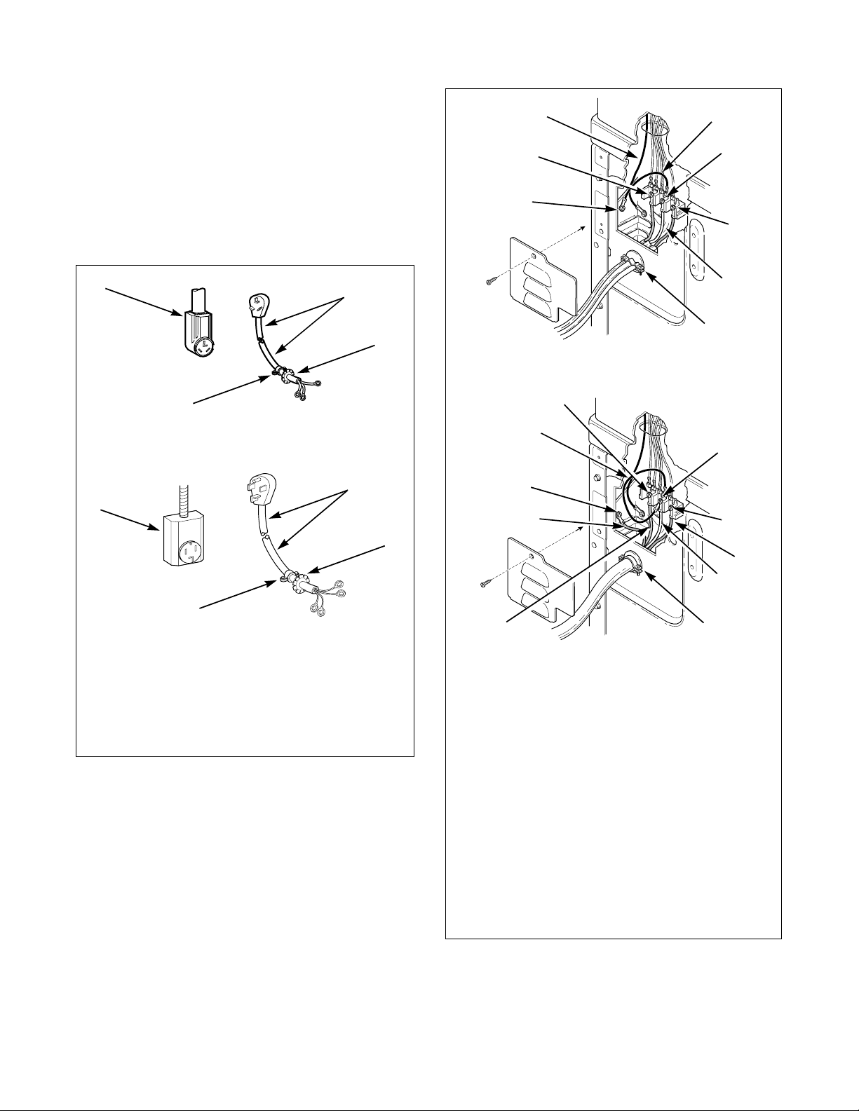
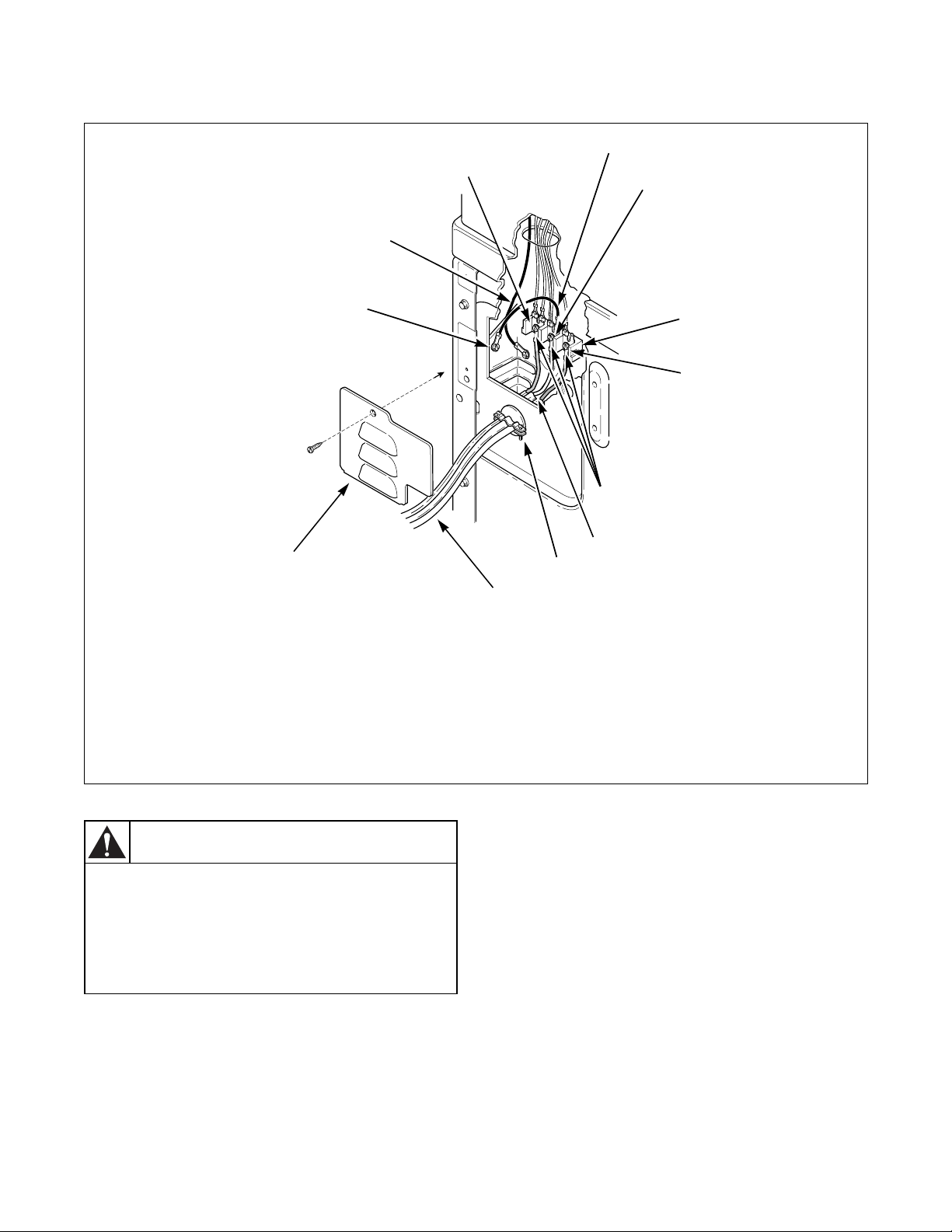
Three-Wire Connection
12
2
1
3
11
6
10
9
1 “L1” Terminal 7 Neutral (White or Center Wire)
2 Ground to Neutral Wire 8 Strain Relief (Not supplied with dryer)
3 Neutral Terminal 9 Power Cord or Direct Wiring (Three-Wire)
4 Terminal Block 10 Access Cover
5 “L2” Terminal 11 Terminal Bracket Ground Screw
6 Slotted Hex Head Screws
(Shipped inside the dryer)
12 Ground Wire
7
8
4
5
D682I
28
© Copyright, Alliance Laundry Systems LLC – DO NOT COPY or TRANSMIT© Copyright, Alliance Laundry Systems LLC – DO NOT COPY or TRANSMIT© Copyright, Alliance Laundry Systems LLC – DO NOT COPY or TRANSMIT© Copyright, Alliance Laundry Systems LLC – DO NOT COPY or TRANSMIT
Figure 19
510969
Page 31

Installation
To reduce the risk of electrical shock,
disconnect the electrical power to the dryer
before proceeding.
W137
WARNING
Four-Wire Power Cord
IMPORTANT: Use only a U.L. listed No. 10 A.W.G.
(copper wire only) four conductor power supply
cord kit rated 240 Volts (minimum)
30 Amperes and labeled as suitable for use in a
clothes dryer.
NOTE: The power cord is not supplied with the
dryer when the dryer is shipped from the factory,
therefore, disregard steps 2 and 3 below when
connecting a four-wire power cord to a new dryer.
If the dryer has a three-wire cord attached, then
complete steps 1 through 12.
1. Remove the screw holding the access plate to the
rear of the dryer cabinet.
2. Remove the three screws holding the three wires
to the terminal block terminals. Save these
screws.
3. Loosen the strain relief screw and pull the cord or
wires out through the rear of the dryer.
4. Remove the terminal bracket ground screw
holding the ground wire to the terminal block
mounting bracket. Save the screw.
NOTE: ON NEW DRYERS, this is the ground wire
that goes from the neutral (center) terminal on the
terminal block to the mounting bracket.
8. Using the three wire-binding (10-32 x 3/8")
screws from the accessories envelope located
inside the cylinder (unless the screws were
previously removed in step 2), attach the power
cord wires to the terminal block terminals as
follows:
a. Red to Red
b.Black to Black
c. White to White (refer to NOTE below)
NOTE: When installing the white wire, loop the
free eyelet end of the ground wire (from step 4) and
place it together with the white wire and attach
both wires to the neutral (center) terminal on the
terminal block. Refer to Figure 21.
IMPORTANT: Failure to tighten the nuts firmly on
the terminal block may result in power cord wire
failure.
9. Tighten the two strain relief screws to secure the
power cord.
10. Recheck all screws to be sure they are tight.
11. Check the continuity of the ground connection
before plugging the cord into an outlet. Use an
acceptable indicating device connected to the
center grounding pin of the plug and the green
screw on the back of the cabinet. Refer to
Figure 18.
12. Reinstall the access plate and screw to the rear of
the dryer cabinet.
1
2
3
Install four-wire power cord
5. Route the end of the four-wire power cord
through the strain relief. DO NOT tighten the
strain relief screws at this time.
6. Insert the end of power cord and strain relief
through the hole in the rear of the dryer cabinet.
Install the strain relief nut from the inside of the
cabinet and tighten firmly.
7. Attach the green ground wire (from the four-wire
power cord) to the terminal block mounting
bracket using the hex head screw removed in
step 4. Tighten the screw firmly.
510969
© Copyright, Alliance Laundry Systems LLC – DO NOT COPY or TRANSMIT
4
D815I
1 Typical Four-Wire Receptacle
2 Power Cord – Not supplied with dryer
(Four-Wire)
3 Strain Relief Nut
4 Strain Relief
Figure 20
29
Page 32

Installation
Dryer is shown with the access cover
removed for illustration purposes only. To
reduce the risk of an electric shock, NEVER
operate the dryer with the access cover
removed.
W136
WARNING
Four-Wire Connection
1
11
13
12
1
11
2
3
4
5
6
D683I
10
1 Ground Wire 8 Neutral (White Wire)
2 White Wires 9 Strain Relief
3 Neutral Terminal 10 Power Cord (Four-Wire)
4 Black Wire 11 Red Wire
5 Terminal Block 12 Terminal Bracket Ground Screw
6 “L2” Terminal 13 “L1” Terminal
7 Slotted Hex Head Screws (Shipped inside the
dryer or removed in step 2)
9
8
7
4
Figure 21
D683I
30
© Copyright, Alliance Laundry Systems LLC – DO NOT COPY or TRANSMIT© Copyright, Alliance Laundry Systems LLC – DO NOT COPY or TRANSMIT© Copyright, Alliance Laundry Systems LLC – DO NOT COPY or TRANSMIT© Copyright, Alliance Laundry Systems LLC – DO NOT COPY or TRANSMIT
510969
Page 33

Installation
To reduce the risk of fire, electric shock or
personal injury, all wiring and grounding
MUST conform with the latest edition of the
National Electrical Code ANSI/NFPA 70 or
the Canadian Electrical Code, CSA C22.1,
and such local regulations as might apply. It
is the customer’s responsibility to have the
wiring and fuses checked by a qualified
electrician to make sure the laundry room
has adequate electrical power to operate
the dryer.
W035
WARNING
This dryer is equipped with a three-prong
(grounding) plug for your protection
against shock hazard and should be
plugged directly into a properly grounded
three-prong receptacle. Do not cut or
remove the grounding prong from this plug.
W036
WARNING
Electrical Requirements
Gas Dryers
(120 Volt, 60 Hertz, with 3-Prong Grounding Plug)
NOTE: The wiring diagram is located inside the
control hood.
● The dryer is designed to be operated on a
separate branch, polarized, three-wire, effectively
grounded, 120 Volt, 60 Hertz, AC (alternating
current) circuit protected by a 15 Ampere fuse,
equivalent fusetron or circuit breaker.
1
120 ± 12
V.A.C.
5
STANDARD 120 VOLT, 60 HERTZ, 3-WIRE
EFFECTIVELY GROUNDED CIRCUIT
1 L1
2 Ground
3 Neutral
4 Round Grounding Prong
5 Neutral Side
120 + 12
4
2
V.A.C.
120 ± 12
V.A.C.
3
D799I
● The three-prong grounding plug on the power
cord should be plugged directly into a polarized
three-slot effectively grounded receptacle rated
120 Volts AC (alternating current) 15 Amps.
Refer to Figure 22 to determine correct polarity
of the wall receptacle.
NOTE: A qualified electrician should check the
polarity of the wall receptacles. If a voltage reading
is measured other than that illustrated, the
qualified electrician should correct the problem.
● DO NOT OPERATE OTHER APPLIANCES
ON THE SAME CIRCUIT WHEN THIS
APPLIANCE IS OPERATING. DO NOT
OVERLOAD CIRCUITS! Refer to Figure 23.
510969
© Copyright, Alliance Laundry Systems LLC – DO NOT COPY or TRANSMIT
Figure 22
DO NOT OVERLOAD
CIRCUITS
D009I
Figure 23
WARNING
To reduce the risk of an electric shock or
fire, DO NOT use an extension cord or an
adapter to connect the dryer to the
electrical power source.
W037
31
Page 34

Installation
Improper connection of the equipmentgrounding conductor can result in a risk of
electric shock. Check with a qualified
electrician or service person if you are in
doubt as to whether the dryer is properly
grounded.
W038
WARNING
Grounding Instructions
● The dryer must be grounded. In the event of
malfunction or breakdown, grounding will
reduce the risk of electric shock by providing a
path of least resistance for electric current. The
dryer is equipped with a cord having an
equipment-grounding conductor and a three
prong grounding plug. The plug must be plugged
into an appropriate outlet that is properly
installed and grounded in accordance with all
local codes and ordinances.
● DO NOT modify the plug provided with the
dryer – if it will not fit the outlet, have a proper
outlet installed by a qualified electrician.
● If the laundry room’s electrical supply does not
meet the above specifications and/or if you are
not sure the laundry room has an effective
ground, have a qualified electrician or your local
electrical utility company check it and correct
any problems.
32
© Copyright, Alliance Laundry Systems LLC – DO NOT COPY or TRANSMIT© Copyright, Alliance Laundry Systems LLC – DO NOT COPY or TRANSMIT© Copyright, Alliance Laundry Systems LLC – DO NOT COPY or TRANSMIT© Copyright, Alliance Laundry Systems LLC – DO NOT COPY or TRANSMIT
510969
Page 35

Gas Requirements
(Gas Dryers)
NOTE: The gas service to a gas dryer must
conform with the local codes and ordinances, or in
the absence of local codes and ordinances, with the
latest edition of the National Fuel Gas Code ANSI
Z223.1/NFPA 54 or the CAN/CGA-B149, National
Gas Installation Code.
Natural Gas, 1,000 Btu/ft
must be supplied at 6.5 ± 1.5 inch water column
pressure.
For proper operation at altitudes above 2,000 feet
(610 m) the natural gas valve spud orifice size must be
reduced to ensure complete combustion. Refer to
Table 1.
L.P. (Liquefied Petroleum) Gas, 2,500 Btu/ft
3
MJ/m
), service must be supplied at 10 ± 1.5 inch
water column pressure.
NOTE: DO NOT connect the dryer to L.P. Gas
Service without converting the gas valve. A 458P3
L.P. Gas Conversion Kit must be installed by the
Manufacturer’s Authorized Dealers, Distributors,
or local service personnel.
3
(37.3 MJ/m3), service
3
(93.1
Installation
WARNING
To reduce the risk of gas leaks, fire or
explosion:
• The dryer must be connected to the type
of gas as shown on nameplate located in
the door recess.
• Use a new flexible stainless steel
connector.
• Use pipe joint compound insoluble in L.P.
(Liquefied Petroleum) Gas, or Teflon tape,
on all pipe threads.
• Purge air and sediment from gas supply
line before connecting it to the dryer.
Before tightening the connection, purge
remaining air from gas line to dryer until
odor of gas is detected. This step is
required to prevent gas valve
contamination.
• Do not use an open flame to check for gas
leaks. Use a non-corrosive leak detection
fluid.
• Any disassembly requiring the use of
tools must be performed by a suitably
qualified service person.
W316
NOTE: The dryer and its individual shut-off valve
must be disconnected from the gas supply piping
system during any pressure testing of that system
at test pressures in excess of 1/2 psi (3.45 kPa).
NOTE: When connecting to a gas line, an equipment
shutoff valve must be installed within 6' (1.8 m) of
the dryer. An 1/8" N.P.T. pipe plug must be
installed as shown. Refer to Figure 24.
Natural Gas Altitude Adjustments
Altitude Orifice Size
feet m # inches mm
2,000 610 41 0.0960 2.44 503776
3,000 915 42 0.0935 2.37 503777
5,500 1,680 43 0.0890 2.26 503778
7,000 2,135 44 0.0860 2.18 58719
9,000 2,745 45 0.0820 2.08 503779
10,500 3,200 46 0.0810 2.06 503780
Tab le 1
Part
Number
510969
© Copyright, Alliance Laundry Systems LLC – DO NOT COPY or TRANSMIT
33
Page 36

Installation
1
5
1 New Stainless Steel Flexible Connector –
Use only if allowed by local codes
(Use Design A.G.A. Certified Connector)
2 1/8" N.P.T. Pipe Plug
(For checking inlet gas pressure)
3 Equipment Shut-Off Valve – Installed within 6'
(1.8 m) of dryer
2
4
3
D233I
D233I
4 Black Iron Pipe
Shorter than 20' (6.1 m) – Use 3/8" pipe
Longer than 20' (6.1 m) – Use 1/2" pipe
5 3/8" N.P.T. Gas Connection
Figure 24
34
© Copyright, Alliance Laundry Systems LLC – DO NOT COPY or TRANSMIT© Copyright, Alliance Laundry Systems LLC – DO NOT COPY or TRANSMIT© Copyright, Alliance Laundry Systems LLC – DO NOT COPY or TRANSMIT© Copyright, Alliance Laundry Systems LLC – DO NOT COPY or TRANSMIT
510969
Page 37

Installation
Location Requirements
Select a location with a solid floor. Dryers installed in
residential garages must be elevated 18 inches (46 cm)
above the floor.
No other fuel burning appliance should be installed in
the same closet with the dryer.
The dryer must not be installed or stored in an area
where it will be exposed to water and/or weather.
1
B
Leveling legs can be adjusted from inside the dryer
with a 1/4" driver. All four legs must rest firmly on the
floor so the weight of the dryer is evenly distributed.
The dryer must not rock.
The dryer needs sufficient clearance and an adequate
air supply for proper operation and ventilation, and for
easier installation and servicing. (Minimum clearances
are shown in Figure 25).
F
2 (G)
E
D
A
**42"
(106.7 cm)
A
FRONT VIEW
(w/o Closet Door)
Area Description
A Dryer sides and rear clearance 0" (0 cm) 0" (0 cm)
B Dryer top clearance 12" (30.5 cm) 12" (30.5 cm)
C Dryer front clearance Not Applicable 2" (5.1 cm)
D Exhaust duct clearance to combustible material 2" (5.1 cm) 2" (5.1 cm)
E Weather hood to ground clearance 12" (30.5 cm) 12" (30.5 cm)
F Distance from floor or ceiling to hole edge Not Applicable 3" (7.6 cm)
G* Area of centered air openings in closet door Not Applicable 40 sq. in./open (260 sq. cm)
A
C
SIDE VIEW
3
Free Standing/Alcove
Installation
(Refer to Illustration)
FRONT VIEW
(Closet Door)
Closet Installation
(Refer to Illustration)
*Louvered door with equivalent air openings is acceptable. (Minimum clearances are shown.)
** NOTE: For new installations, locate top of wall vent 42 inches (106.7 cm) above floor to make venting easier to
connect.
1 Closet Door 3 Outer Wall of Enclosure
2 Centered Air Openings
(Two openings minimum)
F
D337I
D337I
510969
Figure 25
© Copyright, Alliance Laundry Systems LLC – DO NOT COPY or TRANSMIT
35
Page 38

Installation
A clothes dryer produces combustible lint.
To reduce the risk of fire and combustion
gas accumulation the dryer MUST be
exhausted to the outdoors.
W116
This gas appliance contains or produces a
chemical or chemicals which can cause
death or serious illness and which are
known to the State of California to cause
cancer, birth defects, or other reproductive
harm. To reduce the risk from substances in
the fuel or from fuel combustion, make sure
this appliance is installed, operated, and
maintained according to the instructions in
this manual.
W115
To reduce the risk of fire and the
accumulation of combustion gases, DO NOT
exhaust dryer air into a window well, gas
vent, chimney or enclosed, unventilated
area, such as an attic, wall, ceiling, crawl
space under a building or concealed space
of a building.
W045
To reduce the risk of fire, DO NOT use
plastic or thin foil ducting to exhaust the
dryer.
W354
WARNING
Dryer Exhaust Requirements
DO NOT use sheet metal screws on exhaust pipe joints
or other fastening means which extend into the duct
that could catch lint and reduce the efficiency of the
exhaust system. Secure all duct joints with duct tape or
pop-rivets.
May Be
Description Kit P/N
Exhaust Duct
(4" Dia.)
Flexible Metal Duct
(4" Dia.)
Weather Hoods, with
hinged dampers (4")
Directional Exhaust
Kit
Tape Not Available Yes
Not Available Yes
521P3 Yes
Not Available Yes
528P3 No
Obtained
Locally
NOTE: Kits described above are optional exhaust
system materials available at extra cost.
Exhaust System Materials
Exhaust system materials are not supplied with the
unit.
Exhaust duct must be 4 inches (10.2 cm) in diameter
having no obstructions. Rigid metal duct is
recommended. Non-combustible flexible metal duct is
acceptable. Do not use plastic or thin foil ducting,
because it contributes to poor drying performance and
collects lint, which can lead to a fire hazard.
Never install flexible duct in concealed spaces, such as
a wall or ceiling.
36
© Copyright, Alliance Laundry Systems LLC – DO NOT COPY or TRANSMIT© Copyright, Alliance Laundry Systems LLC – DO NOT COPY or TRANSMIT© Copyright, Alliance Laundry Systems LLC – DO NOT COPY or TRANSMIT© Copyright, Alliance Laundry Systems LLC – DO NOT COPY or TRANSMIT
D333I
DO DON’T
D333I D335I
Figure 26
D335I
510969
Page 39

Installation
Make-Up Air Requirements
It is important that the laundry room has adequate
make-up air for the dryer(s). A dryer exhausts 220 cfm
(measured at back of the dryer) and sufficient make-up
air must be supplied to replace the air exhausted by the
dryer.
Make-Up Air Dos and Don’ts
Do
● Supply adequate air for ventilating air, drying air
and gas dryer combustion air.
NOTE: Each-dryer pocket must have 40 square
inches (260 cm
air for proper operation.
● Energy efficient buildings with low air
infiltration rates should be equipped with an air
exchanger that can accommodate on demand
make-up air needs in the laundry room. These
devices can be obtained through your building
contractor or building material suppliers.
Don’t
2
) of unobstructed flow of make-up
Exhaust Direction
The dryer can be exhausted to the outdoors through the
back, left, right or bottom of the dryer. EXCEPTION:
Gas dryers cannot be vented out the left side
because of the burner housing.
Dryer is shipped from factory ready for rear exhaust;
no kits required.
Exhausting the dryer through sides or bottom can be
accomplished by installing a DK1 Sales Accessory
(Directional Exhaust Kit 528P3) available as optional
equipment at extra cost.
● Draw make-up air from a room containing a gas
fired water heater.
● Draw make-up air from a room containing a dry
cleaner or a hair salon.
528P3 DIRECTIONAL EXHAUST KIT
Figure 27
D361I
D361I
510969
© Copyright, Alliance Laundry Systems LLC – DO NOT COPY or TRANSMIT
37
Page 40

Installation
Exhaust System
IMPORTANT: Keep exhaust duct as short as
possible.
NOTE: Be certain old ducts are cleaned before
installing your new unit.
For best drying results, recommended maximum
length of exhaust system is shown in Table 2.
Number of
90° Elbows
Maximum length of 4" (10.2 cm) diameter rigid metal duct
0 65 feet (19.8 m) 55 feet (16.8 m)
1 55 feet (16.8 m) 47 feet (14.3 m)
2 47 feet (14.3 m) 41 feet (12.5 m)
3 36 feet (11.0 m) 30 feet (9.1 m)
4 28 feet (8.5 m) 22 feet (6.7 m)
Recommended Use Only for Short Run Installations
4"
(10.2 cm)
To prevent backdraft when dryer is not in operation,
outer end of exhaust pipe must have a weather hood
with hinged dampers (obtain locally).
NOTE: Weather hood should be installed at least
12 inches (30.5 cm) above the ground. Larger
clearances may be necessary for installations where
heavy snowfall can occur.
Weather Hood Type
4"
(10.2 cm)
D673I
2-1/2"
(6.35 cm)
D802I
Maximum length of 4" (10.2 cm) diameter flexible metal duct
0 45 feet (13.7 m) 35 feet (10.7 m)
1 35 feet (10.7 m) 27 feet (8.2 m)
2 30 feet (9.1 m) 21 feet (6.4 m)
3 25 feet (7.6 m) 17 feet (5.2 m)
4 20 feet (6.1 m) 15 feet (4.5 m)
NOTE: Deduct 6 feet (1.8 m) for each additional elbow.
Table 2
38
© Copyright, Alliance Laundry Systems LLC – DO NOT COPY or TRANSMIT© Copyright, Alliance Laundry Systems LLC – DO NOT COPY or TRANSMIT© Copyright, Alliance Laundry Systems LLC – DO NOT COPY or TRANSMIT© Copyright, Alliance Laundry Systems LLC – DO NOT COPY or TRANSMIT
510969
Page 41

Installation
To reduce the risk of electric shock,
disconnect the electrical service to the dryer
before cleaning.
W043
WARNING
Exhaust System Maintenance
The dryer interior and the complete exhaust system
should be inspected after one year of use and cleaned
if necessary. Inspect and clean exhaust duct every one
to two years as required thereafter. The weather hood
should be checked frequently to make sure the
dampers move freely, dampers are not pushed in and
that nothing has been set against them. This
maintenance work should be done by a qualified
service person.
Exhausting the dryer in hard-to-reach locations can be
accomplished by installing the 521P3 Flexible Metal
Vent Kit, available as optional equipment at extra cost.
The kit comes in two halves that can be separately
attached to the dryer and wall outlet. Once attached,
the dryer can be slid back into position and the two
halves can be connected from the front.
Dryer Airflow
Efficient dryer operation requires proper dryer airflow.
Proper dryer airflow can be evaluated by measuring
the static pressure.
Static pressure in the dryer’s exhaust duct should be no
greater than that shown in Figure 29. (Check with
dryer running and no load.)
NOTE: This can be measured with a manometer
placed on the exhaust duct approximately two feet
(61 cm) from the dryer. Refer to Figure 29.
MAXIMUM STATIC
PRESSURE IN
WATER COLUMN
1
0.6 inches (1.5 cm)
D615I
521P3 FLEXIBLE METAL VENT KIT
Figure 28
2
DR012A-IN
MEASURING STATIC PRESSURE
D012I
1 Manometer
2 Exhaust Duct
Figure 29
IMPORTANT: DO NOT block the airflow at the
bottom of the dryer’s front panel with laundry,
rugs, etc. Blockage will decrease airflow through
the dryer, thus reducing the efficiency of the dryer.
H615I
510969
© Copyright, Alliance Laundry Systems LLC – DO NOT COPY or TRANSMIT
39
Page 42

Installation
Multi-Dryer Installation Exhaust
Requirements
WARNING
Figure 30 shows a typical example of a multiple dryer
installation. Note how each dryer has its own exhaust
system vented to the central exhaust duct.
IMPORTANT: Static pressure in dryer’s exhaust
duct should be no greater than that shown in
Figure 29. This can be measured with a manometer
placed on the exhaust duct approximately two feet
(61 cm) from the dryer. All dryers connected to the
main collector duct should be in operation when
pressure is checked.
Installing an exhaust system does not eliminate the
necessity of cleaning the dryer lint filter before each
load. The dryer interior and the complete exhaust
system should be cleaned periodically by a qualified
service person to remove any lint build-up.
1
To reduce the risk of electric shock,
disconnect the electrical service to the dryer
before cleaning.
W043
IMPORTANT: DO NOT block the airflow at the
bottom of the dryer’s front panel with laundry,
rugs, etc. Blockage will decrease airflow through
the dryer, thus reducing the efficiency of the dryer.
2
24" (61 cm)
MINIMUM
CLEARANCE TO
ROOF/GROUND
3
1 58786 Backdraft Damper (Available through
your local authorized parts source)
2 Clean Out Cover (Must be provided). Inspect
monthly.
40
© Copyright, Alliance Laundry Systems LLC – DO NOT COPY or TRANSMIT© Copyright, Alliance Laundry Systems LLC – DO NOT COPY or TRANSMIT© Copyright, Alliance Laundry Systems LLC – DO NOT COPY or TRANSMIT© Copyright, Alliance Laundry Systems LLC – DO NOT COPY or TRANSMIT
METERED MODELS
ILLUSTRATED
D797I
3 Weather Hood or Sweep Elbow
(No cap or screen)
Figure 30
510969
Page 43

Installation
3
1
4
5
24" (61 cm)
MINIMUM
CLEARANCE TO
ROOF/GROUND
CONNECT TO DRYER
VERTICAL EXHAUST INSTALLATION
2
1
KJIHGFEDCBA
5
AIR
FLOW
30°
EXHAUST AIR FLOW
MAXIMUM LENGTH OF DUCT
30 feet (9.1 m)
HORIZONTAL EXHAUST INSTALLATION
1 NOTE: Where the exhaust duct pierces a
combustible wall or ceiling, the opening must be
sized per local codes.
3 2" (5 cm) Minimum or Clearance per Local
Codes
4 No Screen or Cap
2 Wall 5 Clean Out Cover
Figure 31
2
3
24" (61 cm)
EXHAUST
OUTLET
CLEARANCE TO
ROOF/GROUND
– Inspect Monthly
4
MINIMUM
D686I
D686I
WARNING
To reduce the risk of fire and the
accumulation of combustion gases, DO NOT
exhaust dryer air into a window well, gas
vent, chimney or enclosed, unventilated
area, such as an attic, wall, ceiling, crawl
space under a building or concealed space
of a building.
D753I
1 Roof
2 No Screen or Cap
3 Wall
4 2" (5 cm) Minimum
5 NOTE: Where the exhaust duct pierces a
combustible wall or ceiling, an opening must
be sized as shown or per local codes.
W045
Figure 32
510969
© Copyright, Alliance Laundry Systems LLC – DO NOT COPY or TRANSMIT
41
Page 44

Installation
Duct
Station
A 4 inches (10.2 cm)
B 8 inches (20.3 cm)
C 9 inches (22.9 cm)
D 10 inches (25.4 cm)
E 11 inches (27.9 cm)
F 12 inches (30.5 cm)
G 13 inches (32.6 cm)
H 14 inches (35.6 cm)
I 15 inches (38.1 cm)
J 15 inches (38.1 cm)
K 16 inches (40.6 cm)
Minimum Diameter of
Collector Duct
A Backdraft Damper, Part No. 58786 (obtain locally),
should be installed in a 4 inch (10.2 cm) diameter
VERTICAL duct system. This will prevent a backdraft
when dryer is not in use, and will keep the exhaust air
in balance within the central exhaust system.
Lint Filter
CLEAN THE LINT FILTER BEFORE DRYING
EACH LOAD. (Refer to Figure 33 for lint filter
location.) Cleaning the lint filter is important because
a layer or pad of lint on the filter will block the flow of
air through the dryer, thus reducing the efficiency of
the dryer. The clothes will take longer to dry and
energy will be wasted.
1
D608I
D608I
1 Lint Filter
Figure 33
Motor Overload Protector
The motor overload protector stops the motor and
shuts the heat off automatically in the event of an
overload. After cooling, the overload protector will
reset itself. The dryer can be restarted by pressing the
PUSH-TO-START button. If the overload protector
cycles again, remove the unit from use and call the
service person to correct the problem.
42
© Copyright, Alliance Laundry Systems LLC – DO NOT COPY or TRANSMIT© Copyright, Alliance Laundry Systems LLC – DO NOT COPY or TRANSMIT© Copyright, Alliance Laundry Systems LLC – DO NOT COPY or TRANSMIT© Copyright, Alliance Laundry Systems LLC – DO NOT COPY or TRANSMIT
510969
Page 45

Operation
Operation Instructions for
Electromechanical Dryers
IMPORTANT: Before using dryer for the first time,
use an all-purpose cleaner, or a detergent and
water solution, and a damp cloth to remove
shipping dust from inside of dryer drum.
IMPORTANT: Remove all sharp objects from
laundry to avoid tears and rips to items during
normal machine operation.
Step 1: Clean Lint Filter
Clean lint filter before each use.
Step 3: Close Loading Door
Close loading door. Dryer will not operate with the
door open.
D688I
D688I
Figure 36
Step 4: Set Fabric Selector
Select NORMAL for cottons, PERM PRESS for
permanent press, DELICATE for sensitive items or
FLUFF (NO HEAT) for items that require no heat.
D608I
Figure 34
Step 2: Load Laundry
Load clothes loosely into dryer drum. Add fabric
softener sheet if desired.
D609I
Figure 35
D608I
D609I
NOTE: Always follow manufacturer’s care label
instructions.
PERM
DELICATE
PRESS
NORMAL
FLUFF
(NO HEAT)
FABRIC SELECTOR
D342I
D342I
Figure 37
510969
© Copyright, Alliance Laundry Systems LLC – DO NOT COPY or TRANSMIT
43
Page 46

Operation
W297I
METERED MODELS
Step 5: Start Dryer
Metered Models
Place coin(s) in slide and carefully push in as far as
possible and then pull slide out as far as possible. After
IN USE light comes on (indicating start of cycle),
press the PUSH-TO-START button.
W297I
Figure 38
Nonmetered Models
Rotate timer knob to desired time setting (up to
60 minutes). Press the PUSH-TO-START button. IN
USE light will come on (indicating start of cycle).
D774I
NONMETERED MODELS
D774I
Figure 39
Remove knits when slightly damp because overdyring
may cause shrinkage. Do not tumble dry knit woolens.
Should dryer stop before cycle is completed, the motor
overload protector may have cycled. Refer to page 42.
44
© Copyright, Alliance Laundry Systems LLC – DO NOT COPY or TRANSMIT© Copyright, Alliance Laundry Systems LLC – DO NOT COPY or TRANSMIT© Copyright, Alliance Laundry Systems LLC – DO NOT COPY or TRANSMIT© Copyright, Alliance Laundry Systems LLC – DO NOT COPY or TRANSMIT
510969
Page 47

Operation
Operation Instructions for
Electronic Display Control Dryers
IMPORTANT: Before using dryer for the first time,
use an all-purpose cleaner, or a detergent and
water solution, and a damp cloth to remove
shipping dust from inside of dryer drum.
IMPORTANT: Remove all sharp objects from
laundry to avoid tears and rips to items during
normal machine operation.
Step 1: Clean Lint Filter
Clean lint filter before each use.
Step 3: Close Loading Door
Close loading door. Dryer will not operate with the
door open.
D688I
D688I
Figure 42
Step 4: Set Fabric Selector
Select NORMAL (High Temp), PERM PRESS (Med
Temp), DELICATES (Low Temp) or TUMBLE (No
Heat) by pushing touchpad.
D608I
Figure 40
Step 2: Load Laundry
Load clothes loosely into dryer drum. Add fabric
softener sheet if desired.
D609I
Figure 41
NOTE: Always follow manufacturer’s care label
instructions.
D608I
D294I
Figure 43
D609I
510969
© Copyright, Alliance Laundry Systems LLC – DO NOT COPY or TRANSMIT
45
Page 48

Operation
Step 5: Insert Coin(s) or Card
To Insert Money
Insert coin(s) in coin slot. Check pricing as seen on
digital display.
If Additional Time Feature is turned on, additional
dryer time may be purchased at cycle start or while
dryer is running.
W387I
Figure 44
To Insert Card
Insert card into opening. Follow directions on display.
DO NOT REMOVE THE CARD UNTIL DISPLAY
READS “Remove Card.”
Remove knits when slightly damp because overdyring
may cause shrinkage. Do not tumble dry knit woolens.
Step 6: Start Dryer
To start dryer, push START pad.
To stop dryer at any time, open the door. To restart the
dryer, close door and push START pad.
Cycle is completed when time remaining reaches
00 minutes.
D296I
D296I
Figure 46
Indicator Lights
INSERT COINS
INSERT COINS is lit to prompt the user to insert coins
or card to satisfy the vend price for the chosen cycle.
When INSERT COINS is lit, the three digits and
decimal point will display the vend price remaining to
be satisfied.
PUSH START
Figure 45
PUSH START is lit whenever the dryer is not in a
cycle, the full vend price has been satisfied and the
dryer door is closed. When the START pad is pressed,
the cycle will begin or resume. The PUSH START
status word flashes at one-second intervals when
activated.
M330I
46
© Copyright, Alliance Laundry Systems LLC – DO NOT COPY or TRANSMIT© Copyright, Alliance Laundry Systems LLC – DO NOT COPY or TRANSMIT© Copyright, Alliance Laundry Systems LLC – DO NOT COPY or TRANSMIT© Copyright, Alliance Laundry Systems LLC – DO NOT COPY or TRANSMIT
510969
Page 49

Operation
DRYING
DRYING is lit to indicate that one of the heated cycles
(HIGH TEMP, MED TEMP, LOW TEMP) is
currently in operation. The status word DRYING goes
off at the end of a heated cycle or when the COOL
DOWN cycle begins.
DOOR OPEN
DOOR OPEN is lit and flashes at one-second intervals
whenever the dryer door is open.
COOL DOWN
COOL DOWN is lit whenever the COOL DOWN
portion of a heated cycle is active. It is also lit when
the NO HEAT cycle is in operation.
PRICE
PRICE is lit to indicate that the value displayed is the
vend pricing remaining to be satisfied. Once the vend
price is satisfied, the word PRICE will go off.
TIME REMAINING
TIME REMAINING is lit to indicate that the time
displayed by two digits and the colon is the time
remaining (in minutes) in the active cycle. The colon
flashes at one-second intervals and time continually
counts down in an active cycle.
Should dryer stop before cycle is completed, the motor
overload protector may have cycled. Refer to page 42.
510969
© Copyright, Alliance Laundry Systems LLC – DO NOT COPY or TRANSMIT
47
Page 50

Operation
Operation Instructions for MDC
Dryers
IMPORTANT: Before using dryer for the first time,
use an all-purpose cleaner, or a detergent and
water solution, and a damp cloth to remove
shipping dust from inside of dryer drum.
IMPORTANT: Remove all sharp objects from
laundry to avoid tears and rips to items during
normal machine operation.
Step 1: Clean Lint Filter
Clean lint filter before each use.
Step 3: Close Loading Door
Close loading door. Dryer will not operate with the
door open.
D688I
D688I
Figure 49
Step 4: Set Fabric Selector
Select HIGH TEMP, MED TEMP, LOW TEMP or
DELICATES by pushing touchpad.
D608I
Figure 47
Step 2: Load Laundry
Load clothes loosely into dryer drum. Add fabric
softener sheet if desired.
NOTE: Always follow manufacturer’s care label
instructions.
D608I
DRY1926N
DRY1926N
Figure 50
48
D609I
D609I
Figure 48
© Copyright, Alliance Laundry Systems LLC – DO NOT COPY or TRANSMIT© Copyright, Alliance Laundry Systems LLC – DO NOT COPY or TRANSMIT© Copyright, Alliance Laundry Systems LLC – DO NOT COPY or TRANSMIT© Copyright, Alliance Laundry Systems LLC – DO NOT COPY or TRANSMIT
510969
Page 51

Operation
Step 5: Insert Coin(s) or Card
To Insert Money
Insert coin(s) in coin slot. Check pricing as seen on
digital display.
W387I
Figure 51
To Insert Card
Insert card into opening.
Step 6: Start Dryer
To start dryer, push START pad.
To stop dryer at any time, open the door. To restart the
dryer, close door and push START pad.
Cycle is completed when time remaining reaches
00 minutes.
DRY1928N
Figure 53
Indicator Lights
START
DRY1927N
Figure 52
If Additional Time Feature is turned on, additional
dryer time may be purchased at cycle start or while
dryer is running.
Remove knits when slightly damp because overdrying
may cause shrinkage. Do not tumble dry knit woolens.
START is lit whenever the dryer is not in a cycle, the
full vend price has been satisfied and the dryer door is
closed. When the START pad is pressed, the cycle
will begin or resume.
DRYING
DRYING is lit to indicate that one of the heated cycles
(HIGH TEMP, MED TEMP, LOW TEMP or
DELICATES) is currently in operation. DRYING will
turn off at the end of a heated cycle or when the COOL
DOWN cycle begins.
COOL DOWN
COOL DOWN is lit whenever the COOL DOWN
portion of a heated cycle is active. It is also lit when no
heat is programmed for a cycle in operation.
510969
© Copyright, Alliance Laundry Systems LLC – DO NOT COPY or TRANSMIT
49
Page 52

Operation
Operation Instructions for
NetMaster Dryers
IMPORTANT: Before using dryer for the first time,
use an all-purpose cleaner, or a detergent and
water solution, and a damp cloth to remove
shipping dust from inside of dryer drum.
IMPORTANT: Remove all sharp objects from
laundry to avoid tears and rips to items during
normal machine operation.
Step 1: Clean Lint Filter
Clean lint filter before each use.
Step 3: Close Loading Door
Close loading door. Dryer will not operate with the
door open.
D688I
D688I
Figure 56
Step 4: Set Fabric Selector
Select HIGH TEMP, MED TEMP, LOW TEMP or
NO HEAT by pushing touchpad.
D608I
Figure 54
Step 2: Load Laundry
Load clothes loosely into dryer drum. Add fabric
softener sheet if desired.
NOTE: Always follow manufacturer’s care label
instructions.
D608I
D777I
Figure 57
50
D609I
D609I
Figure 55
© Copyright, Alliance Laundry Systems LLC – DO NOT COPY or TRANSMIT© Copyright, Alliance Laundry Systems LLC – DO NOT COPY or TRANSMIT© Copyright, Alliance Laundry Systems LLC – DO NOT COPY or TRANSMIT© Copyright, Alliance Laundry Systems LLC – DO NOT COPY or TRANSMIT
510969
Page 53

Operation
Step 5: Insert Coin(s) or Card
To Insert Money
Insert coin(s) in coin slot. Check pricing as seen on
digital display.
W387I
Figure 58
To Insert Card
Insert card into opening. DO NOT REMOVE THE
CARD UNTIL THE “Remove Card” LED IS LIT.
Step 6: Start Dryer
To start dryer, push START pad.
To stop dryer at any time, open the door. To restart the
dryer, close door and push START pad.
Cycle is completed when time remaining reaches
00 minutes.
D778I
Figure 60
M343I
Figure 59
M343I
If Additional Time Feature is turned on, additional
dryer time may be purchased at cycle start or while
dryer is running.
Remove knits when slightly damp because overdrying
may cause shrinkage. Do not tumble dry knit woolens.
510969
© Copyright, Alliance Laundry Systems LLC – DO NOT COPY or TRANSMIT
51
Page 54

Operation
Indicator Lights
INSERT COINS/CARD
INSERT COINS/CARD is lit to prompt the user to
insert coins or a card to satisfy the vend price. When
INSERT COINS/CARD is lit, the three digits and
decimal point will display the vend price remaining to
be satisfied.
START
START is lit whenever the dryer is not in a cycle, the
full vend price has been satisfied and the dryer door is
closed. When the START pad is pressed, the cycle
will begin or resume.
DRYING
DRYING is lit to indicate that one of the heated cycles
(HIGH TEMP, MED TEMP, or LOW TEMP) is
currently in operation. DRYING will turn off at the end
of a heated cycle or when the COOL DOWN cycle
begins.
COOL DOWN
COOL DOWN is lit whenever the COOL DOWN
portion of a heated cycle is active. It is also lit when
the NO HEAT cycle is in operation.
ADD TIME (Card Models Only)
ADD TIME flashes when a card is inserted while a
cycle is running or when a card is left in the reader for
at least five seconds after cycle has started.
REMOVE CARD (Card Models Only)
REMOVE CARD flashes when a card is inserted or left
in the reader after a transaction is complete. It will also
flash alternately with ADD TIME when a card is
inserted while a cycle is running or when a card is left
in the reader.
52
© Copyright, Alliance Laundry Systems LLC – DO NOT COPY or TRANSMIT© Copyright, Alliance Laundry Systems LLC – DO NOT COPY or TRANSMIT© Copyright, Alliance Laundry Systems LLC – DO NOT COPY or TRANSMIT© Copyright, Alliance Laundry Systems LLC – DO NOT COPY or TRANSMIT
510969
Page 55

Maintenance
Label all wires prior to disconnection when
servicing controls. Wiring errors can cause
improper and dangerous operation.
W049
CAUTION
User-Maintenance Instructions
Lubrication
All moving parts are sealed in a permanent supply of
lubricant or are equipped with oilless bearings.
Additional lubrication will not be necessary.
Care of Your Dryer
Clean the lint filter before drying each load. The lint
filter may be washed if needed. Annually remove lint
filter and screw to vacuum the duct under it.
Ordinarily, the dryer cylinder will need no care.
Wipe the dryer cabinet as needed. If detergent, bleach
or other washing products have been spilled on the
dryer, wipe immediately. Some products will cause
permanent damage if spilled on the cabinet.
Use only a damp or sudsy cloth for cleaning the
control panel. Some spray prewash products may harm
the finish on the control panel.
NOTE: The wiring diagram is located inside the
control panel.
Exhaust System
The exhaust duct should be inspected after one year of
use and cleaned if necessary by a qualified service
person to remove any lint build-up. Inspect and clean
exhaust duct every one to two years as required
thereafter.
The weather hood should be checked frequently to
make sure the dampers move freely, dampers are not
pushed in and that nothing has been set against them.
Keep dryer area clear and free from combustible
materials, gasoline and other flammable vapors and
liquids.
Do not obstruct the flow of combustion and ventilation
air.
NOTE: Verify proper operation after servicing.
For Energy Conservation
● Make sure the lint filter is always clean.
● Do not overload dryer.
● Do not overdry clothes.
● Remove items to be ironed while still damp.
● Large loads of similar fabrics dry the most
efficiently. However, dry permanent press in
smaller loads to prevent wrinkling.
● Use the correct temperature FABRIC
SELECTOR setting for the type of fabric being
dried.
● Locate your dryer so the exhaust duct is as short
and straight as possible.
● Do not open the door during the drying cycle.
● Plan to do your laundry on low humidity days;
your clothes will dry faster.
● Should you plan to dry several loads, do them
one after another, then you do not have to reheat
the dryer unit’s interior parts each time.
510969
© Copyright, Alliance Laundry Systems LLC – DO NOT COPY or TRANSMIT
53
Page 56

Maintenance
Before You Call for Service
You may save time and money by checking the
following:
If the Dryer:
Does
Not
Start
Does
Not
Heat
•
••
•
•
•
••
•
••
•
•
••
••
Does Not Dry
Clothes
Satisfactorily
•
•
Possible Reason – Do This to Correct
Metered Models – Insert coin(s) or card.
Nonmetered models – Turn the timer knob further into the cycle.
Be sure the cord is plugged all the way into the electrical outlet.
Close the loading door.
Make sure the controls are in a HEAT setting.
Metered Models – Activate time accumulator.
Push the coin slide all the way in.
Press the PUSH-TO-START pad.
Has the laundry room fuse blown or become loosened, or is a circuit breaker
OFF? The dryer itself does NOT have an electrical fuse.
Has the motor overload protector cycled? Wait 10 minutes and try again.
Gas Dryers Only – Check to see if the gas valve in the dryer (behind the lower
front panel) and the main gas line valve are turned on.
Clean the lint filter.
Check the exhaust duct to the outside to see if it is kinked, blocked or needs
cleaning.
Check the weather hood to make sure the flappers move freely, are not pushed
in or have not been blocked.
Is the load too small? Small loads may not tumble properly or dry evenly.
54
© Copyright, Alliance Laundry Systems LLC – DO NOT COPY or TRANSMIT© Copyright, Alliance Laundry Systems LLC – DO NOT COPY or TRANSMIT© Copyright, Alliance Laundry Systems LLC – DO NOT COPY or TRANSMIT© Copyright, Alliance Laundry Systems LLC – DO NOT COPY or TRANSMIT
510969
Page 57

Maintenance
If Service Is Required
If service is required, contact the nearest Factory
Authorized Service Center.
If you are unable to locate an authorized service center
or are unsatisfied with the service performed on your
unit, contact:
Alliance Laundry Systems
Shepard Street
P.O. Box 990
Ripon, WI 54971-0990
U.S.A.
Phone: (920) 748-3950
1
When calling or writing about your unit, PLEASE
GIVE THE MODEL AND SERIAL NUMBERS. The
model and serial numbers are located on the
nameplate. The nameplate will be in the location
shown in Figure 61.
Please include a copy of your bill of sale and any
service receipts you have.
WARNING
To reduce the risk of serious injury or death,
DO NOT repair or replace any part of the
unit or attempt any servicing unless
specifically recommended in the usermaintenance instructions or in published
user-repair instructions that you understand
and have the skills to carry out.
W329
1 Nameplate
D063K
Figure 61
510969
© Copyright, Alliance Laundry Systems LLC – DO NOT COPY or TRANSMIT
55
Page 58

Maintenance
Information for Handy Reference
Alliance Laundry Systems
Shepard Street
P.O. Box 990
Ripon, WI 54971-0990
U.S.A.
Phone: (920) 748-3950
Date Purchased
Model Number Serial Number
Dealer’s Name
Dealer’s Address Phone Number
Service Agency
Service Agency Address Phone Number
NOTE: Record the above information and keep your sales slip. Model and serial numbers are located on
the nameplate.
56
© Copyright, Alliance Laundry Systems LLC – DO NOT COPY or TRANSMIT© Copyright, Alliance Laundry Systems LLC – DO NOT COPY or TRANSMIT© Copyright, Alliance Laundry Systems LLC – DO NOT COPY or TRANSMIT© Copyright, Alliance Laundry Systems LLC – DO NOT COPY or TRANSMIT
510969
Page 59

Secadora de ropa
operadas con monedas y
operadas sin monedas
Modelos eléctricos y a gas
Instalación/Operación
Guarde estas instrucciones para referencia en el futuro.
(Si la unidad cambia de dueño, asegúrese de que este manual vaya con la misma).
www.comlaundry.com
D677I
Pieza No. 510969R4
Octubre 2003
Page 60

Page 61

ADVERTENCIA
POR SU PROPIA SEGURIDAD, la información que aparece en este manual debe tomarse en
cuenta para mantener a un mínimo el riesgo de incendio o explosión y para evitar daños a
la propiedad, lesiones personales o la muerte.
• No almacene ni use gasolina u otros vapores o líquidos inflamables cerca de éste ni en
cualquier otro aparato electrodoméstico.
• QUÉ DEBE HACER SI DETECTA OLOR A GAS:
– No trate de usar ningún aparato electrodoméstico.
– No toque ningún interruptor eléctrico; no use ningún teléfono en el edificio.
– Asegúrese de que todas las personas salgan de la habitación, edificio o área.
– Llame de inmediato a su proveedor de gas desde el teléfono de algún vecino. Siga las
instrucciones que le dé el proveedor de gas.
– Si no puede ponerse en contacto con su proveedor de gas, llame a los bomberos.
• Un instalador calificado, una agencia de servicio o el proveedor de gas debe hacer la
instalación y proporcionar el servicio.
IMPORTANTE: El comprador debe consultar al proveedor de gas para obtener instrucciones
acerca de los pasos a seguir en caso de que el usuario detecte olor a gas. Las instrucciones del
proveedor de gas y las notas de SEGURIDAD y ADVERTENCIA directamente arriba deben ser
colocadas en algún lugar visible cerca de la secadora, para que las vea fácilmente la persona que
use la secadora.
W033S
W052S
POR SU PROPIA SEGURIDAD
No almacene ni use gasolina ni vapores o líquidos inflamables cerca de esta secadora ni
de cualquier otro aparato electrodoméstico.
W053S
La información siguiente se aplica al estado de Massachusetts (EE.UU.).
● Esta máquina únicamente puede ser instalada por un plomero o un instalador de gas con licencia de
Massachusetts.
● Esta máquina deberá ser instalada con un conector de gas flexible de 36 pulgadas (91 cm) de longitud.
● Una válvula de cierre de gas del tipo “Mango en T” deberá ser instalada en la línea de suministro de gas de
esta máquina.
● Esta máquina no deberá instalarse en un dormitorio ni en un cuarto de baño.
510969 (SP)
© Copyright, Alliance Laundry Systems LLC – DO NOT COPY or TRANSMIT
59
Page 62

Notas
60
© Copyright, Alliance Laundry Systems LLC – DO NOT COPY or TRANSMIT
510969 (SP)
Page 63

Contenido
Piezas de repuesto............................................................................... 63
Instrucciones de seguridad importantes........................................... 65
Instalación ........................................................................................... 67
Dimensiones aproximades.................................................................... 67
Modelos para operar con monedas .................................................. 67
Modelos para operar sin monedas.................................................... 68
Contador de monedas ........................................................................... 69
Levas de regulación de tiempo ............................................................. 69
Extensión del tragamonedas de la secadora.......................................... 70
Extensón de deslizador abovedada corta ......................................... 70
Extensión de deslizador abovedada larga ........................................ 71
Seguridad adicional .............................................................................. 73
Antes de comenzar................................................................................ 74
Herramientas.................................................................................... 74
Gas ................................................................................................... 74
Ubicación ......................................................................................... 74
Escape .............................................................................................. 74
Servicio eléctrico ............................................................................. 74
Instalación de la secadora ..................................................................... 75
Paso 1: Coloque la secadora en su lugar y nivélela......................... 75
Paso 2: Conecte el sistema de escape de la secadora....................... 75
Paso 3: (Sólo para secadoras a gas) Conecte las tuberías de
suministro de gas............................................................................ 76
Paso 4: (Sólo para secadoras eléctricas) Conecte las
clavijas eléctricas............................................................................ 77
Paso 5: Limpie el interior de la secadora......................................... 78
Paso 6: Conecte la secadora............................................................. 78
Paso 7: Revise la instalación............................................................ 78
Revisión de la fuente de calor............................................................... 79
Secadoras eléctricas ......................................................................... 79
Secadoras a gas ................................................................................ 79
Cómo para invertir la posición de la puerta.......................................... 81
Instalación en construcciones prefabricadas (móviles) ....................... 82
Requisitos eléctricos............................................................................. 83
Secadoras eléctricas ......................................................................... 83
Conexión eléctrica ................................................................................ 85
Cable de corriente de tres conductores ............................................ 85
Conexión de tres conductores.......................................................... 86
Cable de corriente de cuatro conductores ........................................ 87
Conexión de cuatro conductores...................................................... 89
Requisitos eléctricos............................................................................. 90
Secadoras a gas ................................................................................ 90
Requisitos de gas .................................................................................. 92
Requisitos de ubicación ........................................................................ 94
Requisitos para el escape de las secadoras ........................................... 95
Materiales para el sistema de escape ............................................... 95
Requisitos de aire de reposición ...................................................... 96
Qué hacer y qué no hacer................................................................. 96
© Copyright 2003, Alliance Laundry Systems LLC
Reservados todos los derechos. Ninguna sección del presente manual puede ser reproducida o transmitida de forma
alguna o a través de algún otro medio, sin la previa autorización por escrito del editor.
510969 (SP)
© Copyright, Alliance Laundry Systems LLC – DO NOT COPY or TRANSMIT
61
Page 64

Dirección del escape ........................................................................ 96
Sistema de escape ............................................................................ 97
Mantenimiento del sistema de escape.............................................. 98
Flujo de aire de la secadora.............................................................. 98
Requisitos para el escape de instalaciones múltiples de secadoras ...... 99
Filtro de pelusa ..................................................................................... 101
Protector de sobrecarga del motor ........................................................ 101
Operación ............................................................................................ 103
Instrucciones de uso para secadoras electromecánicas......................... 103
Paso 1: Limpie el filtro de pelusa .................................................... 103
Paso 2: Meta la ropa......................................................................... 103
Paso 3: Cierre la puerta del tambor.................................................. 103
Paso 4: Ajuste el selector de tela...................................................... 104
Paso 5: Arranque la secadora........................................................... 104
Instrucciones de uso para secadoras con control electrónico
de pantalla........................................................................................... 105
Paso 1: Limpie el filtro de pelusa .................................................... 105
Paso 2: Meta la ropa......................................................................... 105
Paso 3: Cierre la puerta del tambor.................................................. 105
Paso 4: Ajuste el selector de tela...................................................... 106
Paso 5: Deposite las monedas o introduzca una tarjeta ................... 106
Paso 6: Arranque la secadora........................................................... 106
Luces indicadoras............................................................................. 107
Instrucciones de funcionamiento de las secadoras MDC ..................... 108
Paso 1: Limpie el filtro de pelusa .................................................... 108
Paso 2: Meta la ropa......................................................................... 108
Paso 3: Cierre la puerta del tambor.................................................. 108
Paso 4: Selección de la temperatura conforme a los tejidos ............ 109
Paso 5: Introducción de monedas o de la tarjeta.............................. 109
Paso 6: Puesta en marcha de la secadora ......................................... 110
Luces indicadoras............................................................................. 110
Instrucciones de funcionamiento de las secadoras NetMaster ............. 111
Paso 1: Limpie el filtro de pelusa .................................................... 111
Paso 2: Meta la ropa......................................................................... 111
Paso 3: Cierre la puerta del tambor.................................................. 111
Paso 4: Selección de la temperatura conforme a los tejidos ............ 112
Paso 5: Introducción de monedas o de la tarjeta.............................. 112
Paso 6: Puesta en marcha de la secadora ......................................... 113
Luces indicadoras............................................................................. 113
62
Mantenimiento .................................................................................... 115
Instrucciones de mantenimiento para el usuario................................... 115
Lubricación ...................................................................................... 115
Cuidados a sus secadoras................................................................. 115
Sistema de escape ............................................................................ 115
Conservación de la energía ................................................................... 115
Antes de llamar para solicitar servicio de reparación........................... 116
Si la unidad necesita servicio................................................................ 117
Información de referencia..................................................................... 118
Lista de comprobación del instalador............................. Contraportada
© Copyright, Alliance Laundry Systems LLC – DO NOT COPY or TRANSMIT
510969 (SP)
Page 65

Piezas de repuesto
Si necesita piezas de repuesto, llame al distribuidor
donde haya comprado su unidad de secadoras o
póngase en contacto con:
Alliance Laundry Systems
Shepard Street
P. O. Box 990
Ripon, WI 54971-0990
U.S.A.
Tel éfono: (920) 748-3950
para obtener el nombre y la dirección del distribuidor
autorizado de piezas de repuesto más cercano.
510969 (SP)
© Copyright, Alliance Laundry Systems LLC – DO NOT COPY or TRANSMIT
63
Page 66

Notas
64
© Copyright, Alliance Laundry Systems LLC – DO NOT COPY or TRANSMIT
510969 (SP)
Page 67

Instrucciones de seguridad importantes
Para reducir el riesgo de ocasionar un
incendio, de sufrir una descarga o
sacudida eléctrica, lesiones personales
serias o la muerte, cumpla con estas
precauciones básicas:
W034S
ADVERTENCIA
(Guarde estas instrucciones)
11. Para reducir el riesgo de causar un incendio, NO
SEQUE plásticos ni artículos que contengan
hule, caucho, o materiales similares con textura
de caucho.
12. SIEMPRE limpie el filtro de pelusa después de
cada carga de secado. Las capas de pelusa en el
filtro reducen la eficiencia de secado y aumentan
el tiempo necesario para secar.
1. Lea las instrucciones antes de usar la secadora.
2. Consulte las INSTRUCCIONES PARA
CONECTAR A TIERRA, en el manual de
INSTALACIÓN, para conectar correctamente la
secadora a tierra.
3. No seque prendas que haya limpiado, lavado,
remojado o a las que haya aplicado gasolina,
solventes para lavar en seco o sustancias
inflamables o explosivas, ya que estas sustancias
dejan escapar vapores que pueden causar un
incendio o una explosión.
4. No permita que los niños jueguen sobre o dentro
de alguna secadora. Es necesario supervisar de
cerca a los niños en la cercanía a la secadora.
Ésta es una regla de seguridad para todos los
aparatos electrodomésticos.
5. Antes de que ponga la secadora fuera de servicio
o de que la deseche, quite la puerta del
compartimiento de secado.
6. No meta la mano en la secadora si el tambor de
secado está girando.
7. No instale ni almacene la secadora donde pudiera
quedar expuesta a la intemperie o al agua.
8. No altere los controles.
9. No repare ni reemplace ninguna pieza de la
secadora, ni trate de darle servicio, a menos de
que se recomiende en las instrucciones de
mantenimiento para los usuarios o en
instrucciones publicadas para los usuarios, que
usted pueda comprender y si tiene la habilidad
para hacerlo.
13. Mantenga el área alrededor de la abertura del
escape de aire caliente y el área adyacente libres
de acumulación de pelusa, polvo o tierra.
14. Un técnico calificado debe limpiar
periódicamente el interior de la secadora y el
conducto de escape.
15. Si este aparato no está instalado, no se usa o no
recibe el mantenimiento de acuerdo a las
instrucciones del fabricante, o si los componentes
de este aparato están dañados o maltratados, su
uso puede exponerlo a usted a substancias del
combustible o de los productos de combustión
que pueden causar la muerte o enfermedades
serias y que el Estado de California tiene
conocimiento de que pueden causar cáncer,
defectos en los recién nacidos y otros problemas
reproductivos.
16. La secadora no debe funcionar cuando la puerta
del tambor de secado esté abierta. NO altere el
interruptor de seguridad de la puerta, de tal forma
que la secadora pueda funcionar con la puerta
abierta. La secadora debe dejar de funcionar al
abrir la puerta. No use la secadora si ésta no deja
de funcionar cuando se abre la puerta, o si
comienza a funcionar sin oprimir o girar el
mecanismo de START (arranque). No use la
secadora y llame al técnico de servicio.
17. No coloque en la secadora artículos que se hayan
ensuciado con aceite vegetal o de cocina, ya que
es posible que estos aceites no se eliminen
completamente durante el lavado. Debido a este
aceite sobrante, la tela puede incendiarse por sí
misma.
10. No use suavizadores de ropa ni productos para
eliminar la estática, a menos de que lo
recomiende el fabricante del suavizador de ropa o
del producto para eliminar la estática.
510969 (SP)
© Copyright, Alliance Laundry Systems LLC – DO NOT COPY or TRANSMIT
65
Page 68

Instrucciones de seguridad importantes
18. Para reducir el riesgo de causar un incendio, NO
coloque en la secadora ropa que tenga cualquier
cantidad de alguna sustancia inflamable como
aceite de maquinaria, sustancias químicas
inflamables, diluyentes, etc. o cualquier cosa que
contenga cera o sustancias químicas, como
trapeadores y trapos para limpiar, o cualquier
prenda limpiada en seco en la casa con solventes
para limpiar en seco.
19. Use la secadora sólo para el propósito con el que
fue fabricada, que es secar ropa.
20. Siempre desconecte la corriente eléctrica a la
secadora antes de intentar darle servicio.
Desconecte la corriente eléctrica tirando de la
clavija, no del cable.
21. Si el cordón de alimentación eléctrica está
dañado, deberá ser reemplazado por un cordón o
conjuncto especial, que puede adquirirse a través
del fabricante o de su agente de servicio.
22. Instale la secadora de acuerdo a las
INSTRUCCIONES DE INSTALACIÓN. Todas
las conexiones de energía eléctrica, conexión a
tierra y alimentación de gas deben cumplir con
los códigos locales y, cuando sea necesario, debe
hacerlas un técnico calificado. ¡No lo haga usted
mismo, a menos de que sepa cómo hacerlo!
23. Saque la ropa seca de la secadora
inmediatamente después de que la secadora
detenga su funcionamiento.
26. SIEMPRE siga las instrucciones de cuidados a la
ropa indicados por el fabricante de las prendas.
27. Nunca haga funcionar la secadora si le falta
alguna guarda o panel de protección.
28. NO haga funcionar la secadora si le faltan piezas
o si tiene piezas dañadas.
29. NO evite ningún equipo de seguridad.
30. Si no instala, da mantenimiento y/o hace
funcionar este aparato de acuerdo a las
instrucciones del fabricante, pueden ocasionarse
lesiones personales y/o daños a la propiedad.
IMPORTANTE: Los vapores solventes de las
máquinas de limpieza en seco crean ácidos cuando
pasan por el calentador de la unidad de secado.
Estos ácidos corroen la secadora así como el resto
de la ropa en la carga. Asegúrese de que el aire de
reemplazo no contenga vapores solventes.
IMPORTANTE: Asegúrese de que su secadora
quede instalada correctamente. ¡No la instale a
menos de que sepa cómo hacerlo!
NOTA: Las instrucciones de los avisos de
ADVERTENCIA y los que indican
IMPORTANTE, que aparecen en este manual, no
intentan cubrir todas las posibles condiciones y
situaciones que pudieran llegar a presentarse. Se
debe usar sentido común, precaución y cuidados al
instalar, dar mantenimiento o usar la secadora.
24. Siempre lea y siga las instrucciones del
fabricante que aparecen en los envases de
detergentes para ropa y de productos para ayudar
en la limpieza de la ropa. Preste atención a todos
los avisos de advertencia o precaución. Para
reducir el riesgo de sufrir envenenamiento o
quemaduras por sustancias químicas, en todo
momento mantenga estos productos fuera del
alcance de los niños (de preferencia guárdelos en
algún gabinete cerrado).
25. No seque en la secadora cortinas de fibra de
vidrio, a menos de que la etiqueta indique que se
puede hacer. Si las seca en la secadora, limpie el
tambor de secado con un trapo húmedo para
eliminar todas las partículas de fibra de vidrio.
Siempre póngase en contacto con su distribuidor,
concesionario, técnico de servicio o el fabricante, para
consultar cualquier problema o condición que no
comprenda.
66
© Copyright, Alliance Laundry Systems LLC – DO NOT COPY or TRANSMIT
510969 (SP)
Page 69

Instalación
Dimensiones aproximades
Modelos para operar con monedas
4,5 plg
(11,4 cm)
*36 plg (91,4 cm)
43,2 plg (109,7 cm)
4,0 plg
(10,2 cm)
8,0 plg
23,5 plg
(59,7 cm)
(20,3 cm)
28 plg
(71,1 cm)
0,4 plg
(1,02 cm)
MODELOS ELÉCTRICOS
*Con las patas de nivelación totalmente dentro de la base.
4,5 plg
(11,4 cm)
8,0 plg
23,5 plg
(59,7 cm)
(20,3 cm)
28 plg
(71,1 cm)
0,4 plg
(1,02 cm)
MODELOS A GAS
*Con las patas de nivelación totalmente dentro de la base.
1 Conexión N.P.T. para gas de 3/8 plg
15,4 plg
(39,1 cm)
26,9 plg
(68,3 cm)
D611I
*36 plg (91,4 cm)
43,2 plg (109,7 cm)
4,0 plg
(10,2 cm)
(39,1 cm)
26,9 plg
(68,3 cm)
15,4 plg
2,3 plg
(6 cm)
2,8 plg
(7 cm)
1
DRY22N
NOTA: Las entradas lateral, posterior e inferior
del escape son para conductos de 4 pulgadas
(10,2 cm). Los modelos a gas no pueden tener el
escape al exterior del lado izquierdo del gabinete,
debido a que ahí se encuentra la caja del quemador.
510969 (SP)
© Copyright, Alliance Laundry Systems LLC – DO NOT COPY or TRANSMIT
IMPORTANTE: La unidad de secadoras debe tener
suficiente espacio libre alrededor para que tenga
suficiente ventilación y para facilitar su instalación y
el servicio. Para obtener el rendimiento máximo de
su unidad de secadoras, le recomendamos que deje
más espacio libre alrededor de la unidad de
secadoras que el que se especifica en este manual.
67
Page 70

Instalación
Modelos para operar sin monedas
4,5 plg
(11,4 cm)
*36 plg (91,4 cm)
43,2 plg (109,7 cm)
4,0 plg
(10,2 cm)
8,0 plg
(20,3 cm)
23,5 plg
(59,7 cm)
28 plg
(71,1 cm)
(1,02 cm)
MODELOS ELÉCTRICOS
*Con las patas de nivelación totalmente dentro de la base.
4,5 plg
(11,4 cm)
8,0 plg
(20,3 cm)
0,4 plg
23,5 plg
(59,7 cm)
28 plg
(71,1 cm)
(1,02 cm)
MODELOS A GAS
*Con las patas de nivelación totalmente dentro de la base.
1 Conexión N.P.T. para gas de 3/8 plg
0,4 plg
*36 plg (91,4 cm)
43,2 plg (109,7 cm)
4,0 plg
(10,2 cm)
26,9 plg
(68,3 cm)
26,9 plg
(68,3 cm)
15,4 plg
(39,1 cm)
15,4 plg
(39,1 cm)
2,3 plg
(6 cm)
2,8 plg
(7 cm)
D613I
1
D614I
NOTA: Las entradas lateral, posterior e inferior
del escape son para conductos de 4 pulgadas
(10,2 cm). Los modelos a gas no pueden tener el
escape al exterior del lado izquierdo del gabinete,
debido a que ahí se encuentra la caja del quemador.
68
© Copyright, Alliance Laundry Systems LLC – DO NOT COPY or TRANSMIT
IMPORTANTE: La unidad de secadoras debe
tener suficiente espacio libre alrededor para que
tenga suficiente ventilación y para facilitar su
instalación y el servicio. Para obtener el
rendimiento máximo de su unidad de secadoras, le
recomendamos que deje más espacio libre
alrededor de la unidad de secadoras que el que se
especifica en este manual.
510969 (SP)
Page 71

Instalación
Contador de monedas
(Modelos para operar con monedas)
El contador de monedas instalado de fábrica no
incluye el seguro de la puerta de servicio, el cajón de
monedas, el seguro del cajón de monedas ni las llaves.
Estas piezas deben ser pedidas (a un costo adicional)
de acuerdo a las necesidades del comprador,
directamente del fabricante de su elección.
NOTA: Usted tiene la opción de usar un seguro del
tipo que se atornilla o un seguro de 1/4 de vuelta en
la puerta de servicio del contador de monedas. Si
decide usar un seguro del tipo que se atornilla,
entonces debe usar una ménsula o soporte especial
(dentro de la caja del contador de monedas). NO
use la ménsula ni el soporte especial si utiliza el
seguro de 1/4 de vuelta.
Seguridad del cajón para monedas – Para obtener
seguridad adicional, perfore los dos orificios piloto a
cada lado en la parte delantera de la caja del contador
de monedas a 1/4 ó 5/16 plg (6,4 ó 8,0 mm) e instale
un seguro para bicicleta a través de estos orificios.
NOTA: Antes de poner en uso la secadora, sitúe la
rueda de trinquete y la leva temporizadora en la
posición “OFF” (desactivadas). Consulte la
Figura 1 en cuanto a la posición adecuada.
1
6
5
4
3
2
D775I
Levas de regulación de tiempo
(Exclusivamente en modelos con
tragamonedas de corredera)
El regulador de tiempo de la secadora está equipado
desde la fábrica con una leva de 45 minutos. Si este
tiempo de secado no es adecuado a sus necesidades,
puede encontrar las siguientes levas en el sobre en el
tambor de la secadora.
SECADORAS ELÉCTRICAS
Leva 1-53242 (30 minutos)
Leva 1-53240 (60 minutos)
SECADORAS A GAS
Leva 1-53242 (30 minutos)
Tam bi én se ofrece como equipo opcional (a un costo
adicional) una leva de 60 minutos, número de pieza
53240.
Modificación de la leva temporizadora:
1. Alinee la muesca de la leva con uno de los
dientes de la rueda de trinquete.
7
D775I
1 Espigas de retención
2 Leva temporizadora
3 Muesca
4 Palancas
5 Posición desactivada
6 Rueda de trinquete
7 Posición activada
Figura 1
2. Junte presionando los extremos de las dos
espigas de la leva temporizadora.
3. Separe cuidadosamente del borne la leva
temporizadora alzándola.
510969 (SP)
© Copyright, Alliance Laundry Systems LLC – DO NOT COPY or TRANSMIT
69
Page 72

Instalación
Para reducir el riesgo de descarga
eléctrica, incendio, explosión, lesiones
graves o letales:
• Desconecte la energía eléctrica a la
secadora antes de darle mantenimiento.
• Cierre la válvula de corte de gas de la
secadora antes de darle mantenimiento.
• Nunca arranque la secadora sin los
paneles y protectores colocados.
• Cuando se desconecten los conductores
de tierra durante el mantenimiento, los
mismos deberán volver a conectarse para
asegurar que la secadora quede
debidamente conectada a tierra.
W001SR1
ADVERTENCIA
Extensión del tragamonedas de la
secadora
(Exclusivamente en modelos con
tragamonedas de corredera)
Extensón de deslizador abovedada corta
1. Instale la extensión del tragamonedas Nº 503733
en el lado superior del tragamonedas mediante
dos tornillos con cabeza tipo Phillips (estrella) y
arandelas de seguridad Nº 03950. Apriételos
firmemente. Consulte la Figura 2.
2. Instale el modificador de extensión del
tragamonedas, Nº 501796, como se describe a
continuación:
NOTA: En secadoras equipadas con tragamonedas
Greenwald (excepto los modelos de tragamonedas
Greenwald Comet y el Greenwald Tokette) no es
necesario usar modificador de extensión.
● Tragamonedas ESD – Monte el modificador de
extensión Nº 501796 en la parte inferior de la
extensión del tragamonedas Nº 503733. Alinee el
agujero del modificador de extensión con el
agujero rotulado “A” de la extensión e instale un
tornillo autorroscante Nº 501086. Apriételo
firmemente. Consulte la Figura 2.
● Tragamonedas GREENWALD Comet,
GREENWALD Tokette y MONARCH –
Monte el modificador de extensión Nº 501796 en
la parte inferior de la extensión del tragamonedas
Nº 503733. Alinee el agujero del modificador de
extensión con el agujero rotulado “B” de la
extensión e instale un tornillo autorroscante Nº
501086. Apriételo firmemente. Consulte la
Figura 2.
70
© Copyright, Alliance Laundry Systems LLC – DO NOT COPY or TRANSMIT
1
7
1 Tornillo autorroscante 501086
2 Modificador de extensión de tragamonedas
501796
3 Agujero “A”
4 Agujero “B”
5 Extensión de tragamonedas 503733
6 Tragamonedas
7 Tornillos con cabeza tipo Phillips y arandelas
de seguiridad 03950
Figura 2
2
3
4
5
6
D019K
3. Reinstale el tragamonedas en la caja del medidor
de la secadora.
4. COMPRUEBE QUE LA SECADORA
FUNCIONE CORRECTAMENTE – Conecte el
suministro de energía eléctrica a la secadora.
Inserte la cantidad correcta de monedas en el
tragamonedas. Empuje hacia dentro el
tragamonedas y observe a través de la abertura de
la puerta de servicio de la caja del medidor. La
extensión del tragamonedas debe hacer contacto
con el brazo actuador y regresar a su posición de
reposo junto con el tragamonedas.
Cuando se empuja el tragamonedas
completamente hacia dentro hasta el final de su
recorrido, el tragamonedas se retrae. El brazo
actuador del acumulador debe mantenerse hacia
atrás hasta que el tragamonedas se desplace hacia
adelante y vuelva a hacer contacto con el brazo
actuador, haciendo que el brazo regrese a su
posición inicial. Consulte la Figura 3.
510969 (SP)
Page 73

3
Para reducir el riesgo de descarga
eléctrica, incendio, explosión, lesiones
graves o letales:
• Desconecte la energía eléctrica a la
secadora antes de darle mantenimiento.
• Cierre la válvula de corte de gas de la
secadora antes de darle mantenimiento.
• Nunca arranque la secadora sin los
paneles y protectores colocados.
• Cuando se desconecten los conductores
de tierra durante el mantenimiento, los
mismos deberán volver a conectarse
para asegurar que la secadora quede
debidamente conectada a tierra.
W001SR1
ADVERTENCIA
2
1
1 Tragamonedas
2 Extensión de tragamonedas
3 Brazo actuador del acumulador
4 Modificador de extensión del tragamonedas
Figura 3
4
5. Después de terminar la comprobación de la
secadora, reinstale la puerta de servicio encima
de la caja del medidor.
NOTA: Al reinstalar la puerta de servicio, la parte
frontal de la puerta deberá insertarse formando un
ángulo de unos 45 grados a fin de que las lengüetas
ranuradas se acoplen con la estría interna ubicada
en la parte superior de la caja del medidor.
Extensión de deslizador abovedada larga
510969 (SP)
© Copyright, Alliance Laundry Systems LLC – DO NOT COPY or TRANSMIT
DRY1925N
Instalación
1. Saque el deslizador de monedas a través de la
caja del medidor.
2. Para deslizadores de monedas Comet, Tokette
y Monarch:
Monte la extensión del deslizador, No. 506114,
en la parte superior del deslizador de monedas
con los dos tornillos cabeza de estrella y las
arandelas de bloqueo, No. 511419, y apriételos
firmemente. Consulte la Figura 4.
Para deslizadores de monedas Greenwald y
ESD:
Monte la extensión del deslizador, No. 506114,
en la parte inferior del deslizador de monedas con
los dos tornillos cabeza de estrella y arandelas de
bloqueo, No. 511419, y apriételos firmemente.
Consulte la Figura 4.
3. Instale el modificador de la extensión del
deslizador, No. 501796, de la forma siguiente:
NOTA: Las secadoras equipadas con un deslizador
de monedas Greenwald (excepto el deslizador
Greenwald Comet o el deslizador Greenwald
Tokette) no requieren el uso de modificador de
extensión de deslizador.
● Deslizador de monedas ESD – Monte el
modificador de extensión de deslizador,
No. 501796, en la parte inferior de la extensión
del deslizador, No. 506114. Alinee el agujero del
modificador en el modificador de extensión de
deslizador con el agujero “A” de la extensión del
deslizador e instale el tornillo de autogolpeo,
No. 501086, y apriételo firmemente. Consulte la
Figura 4.
● Deslizador GREENWALD Comet, deslizador
GREENWALD Tokette o deslizador de
monedas MONARCH – Monte el modificador
de extensión de deslizador, No. 501796, en la
parte inferior de la extensión del deslizador,
No. 506114. Alinee el agujero del modificador en
el modificador de extensión de deslizador con el
agujero “B” de la extensión del deslizador e
instale el tornillo de autogolpeo, No. 501086, y
apriételo firmemente. Consulte la Figura 4.
71
Page 74

Instalación
2
1
3
4
5
5
6
6
7
PARA DESLIZADORES
DE MONEDAS COMET,
TOKETTE Y MONARCH
DESLIZADORES DE
MONEDAS
GREENWALD Y ESD
1 Modificador de extensión de deslizador
501796
2 Agujero “A”
3 Agujero “B”
4 Extensión de deslizador 506114
5 Tornillos de cabeza de estrella 03950 y
arandelas de seguridad
6 Deslizador de monedas
7 Tornillo de autogolpeo 501086
DRY1967K
DRY1967K
Cuando se empuja el deslizador hasta el tope (el
brazo del acumulador será girado hacia la parte
posterior) y se retrae el deslizador, el brazo del
accionador del acumulador deberá permanecer en
la parte posterior hasta que la extensión del
deslizador se desplace hacia delante y contacte de
nuevo con el brazo accionador para volver el
brazo a la posición inicial hacia delante. Consulte
la Figura 5.
6. Una vez completada la comprobación de la
secadora, vuelva a instalar la puerta de servicio
en la parte superior de la caja del medidor.
NOTA: Cuando se vuelva a instalar la puerta de
servicio, la parte frontal de la puerta deberá
insertarse a un ángulo de aproximadamente 45°
para poder acoplar las aletas ranuradas con la
nervadura interna de la parte superior de la caja
del medidor.
1
4
2
4. Vuelva a instalar el deslizador de monedas en la
caja del medidor. Consulte la Figura 5.
NOTA: La posición del brazo del acumulador se
encuentra entre la extensión de empuje y tiro de la
extensión del deslizador.
5. COMPRUEBE LA OPERACIÓN DE LA
SECADORA – Conecte la secadora a la
corriente. Ponga el número requerido de monedas
en el deslizador de monedas. Empuje el
deslizador y observe a través de la abertura de la
puerta de servicio de la caja del medidor si la
extensión del deslizador está en contacto con el
brazo del accionador del acumulador y moviendo
el brazo hacia atrás con la carrera del deslizador.
72
Figura 4
© Copyright, Alliance Laundry Systems LLC – DO NOT COPY or TRANSMIT
3
DRY1968K
1 Brazo de accionador de acumulador
2 Modificador de extensión de deslizador
501796 (si fuera requerido)
3 Deslizador de monedas
4 Extensión de deslizador 506114
Figura 5
510969 (SP)
Page 75

Instalación
Seguridad adicional
En la puerta de servicio de la secadora hay un tornillo
Phillips plano. Durante el transporte, este tornillo se
usa para unir la puerta de servicio a la caja del
contador de monedas. Para mayor seguridad, se puede
volver a instalar este tornillo dentro de la cubierta del
tablero de control de su secadora. A continuación se
describe el procedimiento para instalar dicho tornillo.
1. Quite el tornillo de cabeza Phillips de la puerta de
servicio. (Consulte la Figura 6).
2. Saque dos tornillos que sostienen el tablero de
control contra la cubierta del tablero de control.
3. Incline el tablero de control hacia adelante y
colóquelo con cuidado sobre una tela para evitar
dañar el gabinete.
4. Meta el tornillo de cabeza Phillips hacia abajo a
través del orificio “doble D” en la esquina
izquierda posterior de la parte superior del
gabinete (dentro de la cubierta del tablero de
control) hasta que encaje en la tuerca de
retención que está en el esquinero izquierdo
posterior del gabinete.
1
D687I
D687I
1 Orificio “doble D”
Figura 6
5. Apriete el tornillo con los dedos.
IMPORTANTE: No use un destornillador eléctrico
para apretar este tornillo. El par de torsión que
aplicaría este destornillador eléctrico podría
apretar demasiado el tornillo ocasionando daños al
gabinete.
510969 (SP)
© Copyright, Alliance Laundry Systems LLC – DO NOT COPY or TRANSMIT
73
Page 76

Instalación
1 2
3
4
5
Antes de comenzar
Herramientas
Para la mayoría de las instalaciones, necesita las
siguientes herramientas básicas:
1 Llave de tuercas
2 Destornilladores
3 Nivel
4 Cinta de teflón
5 Cinta para ductos
Figura 7
Gas
Las secadoras están equipadas para gas natural con
una conexión N.P.T. para alimentación de gas de
3/8 plg. Para obtener información más detallada,
consulte la sección Requisitos de gas.
Ubicación
D818I
Escape
Use un conducto rígido de metal par los conductos de
escape de las secadoras usando la ruta más corta
posible.
D333I
Figura 8
NOTA: Para obtener información más detallada,
consulte la sección Requisitos para el escape de las
secadoras.
Servicio eléctrico
● SECADORAS ELÉCTRICAS
Las secadoras requieren una alimentación
eléctrica de corriente alterna (CA) monofásica de
3 ó 4 conductores de 120/240 ó 120/208 Voltios,
30 Amperios y 60 Hertzios.
● SECADORAS A GAS
Cada secadora requiere un tomacorriente con
conexión a tierra polarizado de 3 ranuras, de
120 Voltios, 15 Amperios y 60 Hertzios.
NOTA: Para obtener información más detallada,
consulte la sección acerca de Requisitos eléctricos.
Coloque la unidad de secadoras sobre un piso sólido
con un adecuado suministro de aire. Para obtener
información más detallada, consulte la sección
Requisitos de ubicación.
74
© Copyright, Alliance Laundry Systems LLC – DO NOT COPY or TRANSMIT
510969 (SP)
Page 77

Instalación
2
1
3
4
Las secadoras de ropa producen pelusa
combustible. Para reducir el riesgo de
causar un incendio y la acumulación de
gases, las secadoras DEBEN tener una
salida de escape al exterior.
W116S
ADVERTENCIA
Instalación de la secadora
Paso 1: Coloque la secadora en su lugar y
nivélela
Para obtener mayor información consulte la sección
Requisitos de ubicación.
Instale la unidad de secadoras antes de instalar la
lavadora. Así tendrá más espacio para instalar el
conducto de escape.
Instale las cuatro tapas de hule (caucho) que están en
la bolsa de accesorios.
Coloque la secadora en su lugar y ajuste las patas hasta
que la unidad quede nivelada tanto en la dirección
lateral como en la anteroposterior.
● NO use conductos de plástico o de aluminio
delgado.
● Coloque la unidad de secadoras de tal forma que
sus conductos de escape sean lo más cortos
posible.
● Asegúrese de limpiar los conductos que ya hayan
estado en uso anteriormente antes de instalar la
nueva unidad de secadoras.
● Use conducto flexible o rígido de metal con
diámetro de 4 pulgadas (10,2 cm).
● El extremo macho de cada una de las secciones
del conducto deberá apuntar hacia el lado
opuesto a la secadora.
● Use el menor número de codos que sea posible.
● Use cinta adhesiva para conductos o remaches en
todas las uniones del conducto.
● Las secciones del conducto que pasen a través de
áreas no calentadas deberán aislarse para reducir
la condensación y la acumulación de pelusa en
las paredes del conducto.
● Instale registros de tiro invertido en instalaciones
de múltiples secadoras.
D678I
1 Base de la secadora
2 Nivel
3 Pata niveladera
4 Tapa de hule (caucho)
Figura 9
Paso 2: Conecte el sistema de escape de
la secadora
Para obtener mayor información consulte las secciones
Requisitos de ubicación y Requisitos para el escape
de la unidad de secadoras.
● Si no se proporciona una vía de escape
adecuada al aire y/o gases de combustión se
anula la garantía.
D333I
CORRECTO INCORRECTO
D333I D335I
Figura 10
D335I
NOTA: Los materiales para el sistema de conductos
de escape no se incluyen con la unidad de secadoras
(obténgalos localmente).
510969 (SP)
© Copyright, Alliance Laundry Systems LLC – DO NOT COPY or TRANSMIT
75
Page 78

Instalación
Paso 3: (Sólo para secadoras a gas)
Conecte las tuberías de suministro de gas
Para obtener mayor información consulte la sección
Requisitos de gas.
1. Asegúrese de que la unidad de secadoras esté
equipada para usarse con el tipo de gas que tenga
disponible en la lavandería. La unidad de
secadoras está equipada de fábrica para utilizarse
con gas natural con una conexión N.P.T. de
3/8 plg.
2. Quite la tapa instalada para el envío en cada una
de las conexiones de gas en la parte posterior de
cada una de las secadoras. Asegúrese de no
causar daños a las cuerdas de las tuberías al
quitar estas tapas.
1
3. Conecte cada línea de suministro de gas.
4. Apriete con firmeza todas las conexiones. Abra
el suministro de gas y revise todas las conexiones
(internas y externas) con algún fluido no
corrosivo para detección de fugas, para
determinar que no haya fugas de gas.
5. Para la conexión de gas licuado de petróleo,
consulte la sección de Requisitos del suministro
de gas.
53
4
1 Nuevo conector flexible de acero inoxidable –
sólo si lo autorizan las normas locales (utilice un
conector con diseño certificado por A.G.A.).
2 Conector de tubo N.P.T. de 1/8 plg (para medir
la presión de entrada del gas)
3 Válvula de cierre del equipo – instale a una
distancia máxima de 6 pies (1,8 m) de la
secadora
Figura 11
2
D233I
D233I
4 Tuno de hierro negro
Menos de 20 pies (6,1 m) – utilice tubo de 3/8 plg
Más de 20 pies (6,1 m) – utilice tubo de 1/2 plg
5 Conexión de gas N.P.T. de 3/8 plg
76
© Copyright, Alliance Laundry Systems LLC – DO NOT COPY or TRANSMIT
510969 (SP)
Page 79

Paso 4: (Sólo para secadoras eléctricas)
1
2
3
4
ENCHUFE DE CUATRO CONDUCTORES
Conecte las clavijas eléctricas
Instalación
1
2
Para obtener mayor información, consulte la sección
Requisitos eléctricos.
IMPORTANTE: Para cada una de las secadoras,
use solamente un juego de cable con 3 conductores
(sólo alambre de cobre) No. 10 aprobado por los
Laboratorios Underwriter (U.L.) para 240 Voltios
(como mínimo), 30 Amperios y que esté certificado
para uso en secadoras de ropa.
1
4
ENCHUFE DE TRES CONDUCTORES
2
3
D275I
8
7
6
D679I
CONEXIÓN DE TRES CONDUCTORES
8
1
7
1
3
4
5
D679I
3
4
9
10
11
CONEXIÓN DE CUATRO CONDUCTORES
D006I
1 To m ac o rr i en t e t ípico
2 Cable
3 Tuerca del protector contra tirones
4 Protector contra tirones
Figura 12
NOTA: Para obtener información más detallada
acerca de los cables de 3 ó 4 conductores, consulte
la sección Conexión eléctrica.
NOTA: En las casas móviles o donde los códigos no
permitan conectar a tierra a través de un
conductor neutral, es necesario usar un cable de
4 conductores.
NOTA: Se muestra la secadora sin la cubierta de
acceso sólo con propósitos de ilustración. NUNCA
use una secadora que no tenga instalada la cubierta
de acceso.
1 Conductor de conexión a tierra
2 Conductor neutral de conexión a tierra
3 Conexión neutral
4 Conexión “L2”
5 Conductor central (neutral)
6 Protector contra tirones
(no se incluye con la unidad)
7 Tornillo de conexión a tierra
8 Conexión “L1”
9 Conductor negro
10 Conductor blanco (neutral)
11 Conductor rojo
6
D680I
D680I
Figura 13
510969 (SP)
© Copyright, Alliance Laundry Systems LLC – DO NOT COPY or TRANSMIT
77
Page 80

Instalación
Paso 5: Limpie el interior de la secadora
Antes de usar una secadora por primera vez, use un
limpiador para propósitos generales o una solución de
detergente y agua y una tela húmeda para eliminar el
polvo que se acumula durante el envío en el interior
del tambor de cada una de las secadoras.
D604I
Paso 6: Conecte la secadora
Consulte la sección Requisitos eléctricos, y conecte
cada secadora a una fuente de energía eléctrica.
SECADORA ELÉCTRICA
Conecte la secadora a un circuito de 30 amperios.
D275I
Figura 14
D604I
D254I
SECADORA A GAS
Conecte el cable de corriente a un
circuito independiente de 15 amperios.
D254I
Figura 15
Paso 7: Revise la instalación
Consulte la sección Lista de comprobación del
instalador en la contraportada de este manual y
asegúrese de que la unidad de secadoras esté
correctamente instalada.
78
© Copyright, Alliance Laundry Systems LLC – DO NOT COPY or TRANSMIT
510969 (SP)
Page 81

Instalación
Revisión de la fuente de calor
Secadoras eléctricas
Modelos para operar con monedas
Coloque el SELECTOR DE TELA (FABRIC
SELECTOR) en la posición NORMAL. Coloque
monedas en el deslizador y empuje con cuidado el
deslizador lo más posible. La luz indicadora de que la
secadora está en uso (IN USE) se ilumina indicando
que la secadora está lista para comenzar a funcionar.
Cierre la puerta del tambor de secado y oprima con
firmeza el botón OPRIMIR PARA ARRANCAR
(PUSH-TO-START) para que arranque la secadora.
Una vez que la secadora haya funcionado durante tres
minutos, el aire de escape y/o su conducto de escape
deben estar tibios.
Modelos para operar sin monedas
Coloque el SELECTOR DE TELA (FABRIC
SELECTOR) en la posición NORMAL y gire la
perilla selectora de tiempo hasta el 50. Cierre la puerta
del tambor de secado y oprima con firmeza el botón
OPRIMIR PARA ARRANCAR (PUSH-TO-START)
para que arranque la secadora. La luz indicadora de
que la secadora está en uso (IN USE) se ilumina
indicando el inicio del ciclo de secado. Una vez que la
secadora haya funcionado durante tres minutos, el aire
de escape y/o su conducto de escape deben estar tibios.
Secadoras a gas
Durante la revisión de la secadora a gas, observe la
llama del quemador. La llama se puede observar
quitando el panel delantero inferior de cada secadora.
Modelos para operar con monedas
Coloque el SELECTOR DE TELA (FABRIC
SELECTOR) en la posición NORMAL. Coloque
monedas en el deslizador y empuje con cuidado el
deslizador lo más posible. La luz indicadora de que la
secadora está en uso (IN USE) se ilumina indicando
que la secadora está lista para comenzar a funcionar.
Cierre la puerta del tambor de secado y oprima con
firmeza el botón OPRIMIR PARA ARRANCAR
(PUSH-TO-START) para que arranque la secadora.
La secadora comienza a funcionar, el dispositivo de
encendido se pone al rojo y se enciende el quemador
principal.
Modelos para operar sin monedas
Coloque el SELECTOR DE TELA (FABRIC
SELECTOR) en la posición NORMAL y gire la
perilla selectora de tiempo hasta el 50. Cierre la puerta
del tambor de secado y oprima con firmeza el botón
OPRIMIR PARA ARRANCAR (PUSH-TO-START)
para que arranque la secadora. La luz indicadora de
que la secado está en uso (IN USE) se ilumina
indicando el inicio del ciclo de secado, el dispositivo
de encendido se pone al rojo y se enciende el
quemador principal.
IMPORTANTE: Si no se purga todo el aire de la
línea de gas, es posible que el dispositivo de
encendido se apague antes de que el gas se haya
encendido. Si esto sucede, después de
aproximadamente dos minutos, el dispositivo de
encendido intenta una vez más encender el gas.
510969 (SP)
© Copyright, Alliance Laundry Systems LLC – DO NOT COPY or TRANSMIT
79
Page 82

Instalación
Todos los modelos
Una vez que cualquiera de las secadoras haya
funcionado durante aproximadamente cinco minutos,
observe la llama del quemador. Ajuste el obturador de
aire hasta que obtenga una llama suave, uniforme y
azul. (Una llama sin fuerza, con la punta amarilla
indica que falta aire, mientras que una llama muy azul,
grande y excitada indica que está entrando demasiado
aire.) Ajuste el obturador de aire como se indica a
continuación:
1. Afloje el tornillo de fijación del obturador de
aire.
2. Gire el obturador de aire hacia la izquierda hasta
que obtenga una punta amarilla luminosa en la
llama, luego gírelo hacia la derecha lentamente
hasta que obtenga una llama azul constante y
suave.
1
6
2
3. Después de que el obturador de aire haya
quedado ajustado a producir una llama adecuada,
apriete con firmeza el tornillo de fijación.
4. Vuelva a instalar el panel delantero inferior.
ADVERTENCIA
Por su seguridad personal, el panel
delantero inferior de cada una de las
secadoras debe estar en su lugar durante
el uso normal.
W046S
Una vez que la secadora haya funcionado durante
aproximadamente tres minutos, el aire de escape y/o
su conducto de escape deben estar tibios.
3
5
1 Posición cerrada 5 Ta pón de tubería de 1/8 plg (3,1 mm)
2 Manija de la válvula de cierre
3 Tornillo de fijación del obturador de aire 6 Posición abierta
4 Obturador de aire
Figura 16
(para revisar la presión del múltiple)
4
D700I
80
© Copyright, Alliance Laundry Systems LLC – DO NOT COPY or TRANSMIT
510969 (SP)
Page 83

Instalación
1
Saque los cuatro
tornillos que
sostienen las
bisagras.
D310S
B
A
D312S
3
Tire hacia fuera de la
parte inferior del panel
interior de la puerta, y
luego tire hacia abajo,
separando el panel
interior del panel
exterior de la puerta.
D312S
D314S
5
Quite el dispositivo de
cerradura del panel
interior de la puerta y
vuelva a instalarlo en
el lado opuesto.
D314S
D316S
7
Vuelva a meter los
nueve tornillos que
sacó en el paso 2.
D316S
Cómo para invertir la posición de la
puerta
D675I
La puerta de cada una de estas secadoras es
completamente reversible.
Para invertir su posición haga lo siguiente:
2
Saque los nueve
tornillos.
4
Gire el panel de la
puerta 180 grados,
como se indica.
D311S
D311S
D313S
D313S
6
Inserte el forro debajo del
reborde inferior de la
puerta y seguidamente
B
empuje la parte superior
de la puerta hasta que
quede en su lugar.
A
D315S
D315S
8
Con un destornillador,
saque los dos tapones de
la puerta y colóquelos en
el lado opuesto al lado de
la abertura de la puerta.
D317S
D317S
9
Vuelva a instalar los
cuatro tornillos en las
bisagras que sacó en
el paso 1.
510969 (SP)
D606I
D606I
© Copyright, Alliance Laundry Systems LLC – DO NOT COPY or TRANSMIT
81
Page 84

Instalación
Para reducir el riesgo de ocasionar un
incendio o de que se acumulen gases de la
combustión, la secadora debe tener un
ESCAPE AL EXTERIOR. Consulte la
sección Requisitos para el escape de la
secadora.
W047S
ADVERTENCIA
Instalación en construcciones
prefabricadas (móviles)
IMPORTANTE: La instalación debe cumplir
con las normas de construcción y seguridad
para construcciones prefabricadas (móviles),
Título 24 CFR, Parte 32-80 ó con las normas
CAN/CSA-Z240 MH.
La secadora se puede instalar en una construcción
prefabricada (móvil) cumpliendo con estas
instrucciones:
1. IMPORTANTE: Las secadoras a gas DEBEN
fijarse en forma permanente al piso en el
momento de su instalación. Pida el Juego de
instalación de secadoras No. 526P3 para
instalación en una construcción prefabricada
(móvil). Siga las instrucciones que se adjuntan
con el juego.
2. La conexión eléctrica (sólo secadoras eléctricas)
debe ser una conexión de 4 conductores.
(Consulte la página 87).
3. Ventilación: La secadora DEBE tener un escape
al exterior.
● El conducto de escape no debe conectarse a
ningún otro conducto, sistema de ventilación o
chimenea.
● El conducto de escape de la secadora NO DEBE
terminar abajo de la casa móvil.
● Para que la secadora funcione adecuadamente, es
importante que tenga suficiente aire de
reemplazo que provenga del exterior. El área
libre de cualquier abertura para dejar entrar aire
del exterior debe ser de por lo menos 25 plg
2
(163 cm
● Cuando se instala un conducto de escape al
).
2
exterior, es posible instalar la secadora sin
necesidad de dejar espacio a los lados y en la
parte posterior. Entre el conducto de escape y
material de construcción que sea combustible
debe haber un espacio de por lo menos 2 plg
(5,08 cm).
● Los materiales para el sistema de escape no se
incluyen junto con la secadora (obténgalos
localmente).
● El escape de la secadora puede dirigirse al
exterior por el panel posterior, izquierdo, derecho
o inferior. El escape de las secadoras a gas no
puede ser enviado hacia la izquierda debido a
la ubicación de la caja del quemador.
● El conducto de escape de la secadora debe fijarse
a la estructura de la casa móvil.
● Los conductos de escape NO DEBEN estar
conectados entre sí con tornillos para lámina
metálica, ni cualquier otro medio de unión que
entre dentro del conducto.
82
© Copyright, Alliance Laundry Systems LLC – DO NOT COPY or TRANSMIT
ADVERTENCIA
Para reducir el riesgo de causar un
incendio, el conducto de escape y la
campana protectora contra la intemperie
DEBEN ser fabricadas de materiales no
combustibles. Se recomienda usar tubería
rígida o flexible de metal para secadoras de
ropa.
W048S
510969 (SP)
Page 85

Instalación
Para reducir el riesgo de causar un
incendio, una descarga eléctrica o de
sufrir lesiones personales, todo el
cableado y las conexiones a tierra DEBEN
cumplir con la última edición del Código
eléctrico de los EE. UU. ANSI/NFPA 70 ó
con el Código Eléctrico Canadiense, CSA
C22.1, y los reglamentos locales que se
apliquen. Es responsabilidad del
consumidor hacer que un electricista
revise el cableado y los fusibles para
asegurarse de que la lavandería cuenta
con la energía eléctrica adecuada para que
funcionen la secadora.
W035S
ADVERTENCIA
Requisitos eléctricos
Secadoras eléctricas
(Instalación de 120/240 voltios, 60 Hertzios, de
3 conductores)
(Instalación de 120/208 voltios, 60 Hertzios, de
3 conductores)
NOTA: El diagrama de cableado está ubicado
dentro del gabinete del tablero de control.
● La secadora tiene su propio bloque de conexiones
que debe ser conectado a una ramal
independiente de un circuito de 60 Hertzios,
monofásico, de corriente alterna (CA), con
fusibles para 30 Amperios (el circuito debe
tener fusibles a ambos lados de la línea). EL
SERVICIO ELÉCTRICO A LA SECADORA
DEBE SER APROBADO PARA EL
VOLTAJE MÁXIMO QUE APARECE EN
LA PLACA. NO CONECTE LA SECADORA
A UN CIRCUITO DE 110, 115 Ó
120 VOLTIOS. Hay elementos de calentamiento
disponibles para instalación en sus instalaciones
para secadoras que deben ser conectadas en un
servicio eléctrico de distinto voltaje que el
indicado en la placa, tal como uno de 208 Voltios.
● Si la ramal del circuito a la secadora mide 15 pies
(4,5 m) o menos, use cable No. 10 A.W.G. (sólo
de cobre) aprobado por los Laboratorios
Underwriter (U.L.). Si mide más de 15 pies
(4,5 m) use cable No. 8 A.W.G. (sólo de cobre)
aprobado por los Laboratorios Underwriter
(U.L.), o el especificado por los códigos locales.
Permita que el cable tenga suficiente longitud, de
tal forma que pueda mover la secadora cuando
sea necesario.
Instrucciones de cableado y de conexión a
tierra
● La secadora debe estar conectada a alguna pieza
de metal que proporcione conexión a tierra o a un
sistema permanente de cableado, o será necesario
instalar un conductor de conexión a tierra para
equipo en los conductores de circuito conectado a
la conexión a tierra del equipo en la secadora.
510969 (SP)
© Copyright, Alliance Laundry Systems LLC – DO NOT COPY or TRANSMIT
● El cable flexible de conexión entre el
tomacorriente de pared y el bloque de conexiones
de la secadora NO se incluye con la secadora.
El tipo de cable flexible de conexión y el calibre
del cable deben cumplir con los códigos locales y
con las instrucciones que aparecen en las
siguientes páginas.
● El método de cableado de la secadora es opcional
y está sujeto a las normas del código local.
Consulte la Figura 17.
83
Page 86

Instalación
NOTA: El cable flexible de conexión NO se incluye con la unidad de
secadoras eléctricas. El tipo de cable flexible de conexión y el calibre del
cable deben cumplir con los códigos locales y con las instrucciones.
El método de cableado de la unidad de secadoras es opcional y está
sujeto a los requisitos del código local.
NOTA: Conecte la secadora a la fuente de alimentación con el VOLTAJE
NOMINAL MÁXIMO que aparece en la placa.
FUENTE
DE ENERGÍA
1
2
3
Receptáculo
normal de pared
de tres terminales
de 30 amperios
tipo nema
10-30R
120 ± 12
V.C.A.
240 ± 12
V.C.A.
NOTA: Utilice solamente CAB LES DE COBRE.
Para una longitud menor de 15 pies (4,5 m) – use conductores calibre 10 A.W.G.
Para una longitud mayor de 15 pies (4,5 m) – use conductores calibre 8 A.W.G.
120 ± 12
V.C.A.
1 Caja del interruptor de entrada del servicio de
tres conductores, con neutro conectado a tierra,
monofásico, 120/240 voltios de C.A., 60 Hertz.
(consulte la NOTA arriba)
CAJA DE FUSIBLES
INTERMEDIA (puede
omitirse si la caja de
entrada del servicio
tiene fusibles)
RECEPTÁCULO DE PARED
CONEXIÓN DEL CABLE CON EL ENCHUFE
CAJA DE
INTERRUPCIÓN
INTERMEDIA
(puede tener o
no fusibles)
4
5
6
L1 L2 L1 L2
7
4 Cable con forro metálico o no metálico
(solo cable de cobre)
5 Cable de conexión a la secadora
6 Neutro
2 Fusible o cortacircuitos de 30 amperios 7 Bloque de terminales de la secadora
3 Conductor neutro
FUENTE
DE ENERGÍA
CONEXIÓN DIRECTA
D816I
Figura 17
84
© Copyright, Alliance Laundry Systems LLC – DO NOT COPY or TRANSMIT
510969 (SP)
Page 87

Instalación
La secadora está conectada a tierra al
conductor neutral en un bloque de
conexiones. Si la secadora está instalada
en una casa móvil, o si los códigos locales
no permiten conectar a tierra a través del
conductor neutral, proceda como se indica
en las instrucciones para Conexión con
cuatro conductores.
W134S
Para reducir el riesgo de recibir una
descarga eléctrica, desconecte el servicio
eléctrico a la secadora antes de seguir
adelante.
W135S
ADVERTENCIA
Conexión eléctrica
Cable de corriente de tres conductores
1. Saque el tornillo y quite la cubierta de acceso del
bloque de conexiones de la parte posterior del
gabinete de la secadora.
2. Meta los extremos del cable directo a través del
orificio de la fuente de energía (que contiene el
protector contra tirones adecuado) en la parte
posterior del gabinete de la secadora. Consulte la
Figura 19. Conecte el cable de corriente
eléctrica, o el cableado directo, a la conexión del
bloque de conexiones utilizando los tornillos de
sujeción de los tres conductores que están en el
paquete de accesorios en el sobre que
enviamos dentro del tambor de la secadora. Si
la secadora ha sido conectada previamente con
un cable de corriente eléctrica de cuatro
conductores, desconecte el cable de cuatro
conductores invirtiendo los procedimientos que
aparecen en las instrucciones Cable de corriente
eléctrica de cuatro conductores.
IMPORTANTE: Use solamente un juego de cables
de 3 conductores aprobado por los Laboratorios
Underwriter (U.L.) No. 10 A.W.G. (sólo alambre de
cobre) especificado para 240 voltios (mínimo),
30 amperios y adecuado para usarse en secadoras
de ropa.
3. Apriete estos tornillos de sujeción con firmeza.
IMPORTANTE: Si no se aprietan estos tornillos
con firmeza, los conductores pueden zafarse en el
bloque de conexiones.
4. Fije el protector contra tirones al cable de
corriente eléctrica, o a los conductores donde
entran al gabinete de la secadora.
5. Revise la continuidad de la conexión a tierra
antes de conectar el cable de corriente en un
tomacorriente. Use un dispositivo indicador
adecuado conectado a la patilla de conexión
central de la clavija y al tornillo verde en la parte
posterior del gabinete.
6. Vuelva a instalar la cubierta de acceso y
atorníllela.
1
3
1 Patilla redonda de conexión a tierra 3 Dispositivo indicador (debe mostrar continuidad)
2 Tornillo verde en la parte posterior del gabinete
510969 (SP)
© Copyright, Alliance Laundry Systems LLC – DO NOT COPY or TRANSMIT
2
D607I
D607I
Figura 18
85
Page 88

Instalación
Se muestra la secadora sin la cubierta de
acceso sólo con propósitos de ilustración.
Para reducir el riesgo de sufrir una
descarga eléctrica, NUNCA use la secadora
mientras no tenga su cubierta de acceso.
W136S
ADVERTENCIA
Conexión de tres conductores
12
2
1
3
11
6
10
9
1 Conexión “L1” 8 Protector contra tirones (no se entrega con la
2 Conexión a tierra al conductor neutral
3 Conexión neutral 9 Cable de corriente o cableado directo
4 Bloque de conexiones
5 Conexión “L2” 10 Cubierta de acceso
6 Tornillos de cabeza hexagonal acanalada
(se envían dentro de la secadora)
7 Neutral (conductor blanco o central) 12 Conductor de conexión a tierra
11 Tornillo de conexión a tierra de la ménsula del
7
8
secadora)
(tres conductores)
bloque de conexiones
4
5
D682I
86
© Copyright, Alliance Laundry Systems LLC – DO NOT COPY or TRANSMIT
Figura 19
510969 (SP)
Page 89

Instalación
Para reducir el riesgo de recibir una
descarga eléctrica, desconecte el servicio
eléctrico a la secadora antes de seguir
adelante.
W137S
ADVERTENCIA
Cable de corriente de cuatro conductores
IMPORTANTE: Use solamente un juego de cable
de corriente eléctrica de cuatro conductores
aprobado por los Laboratorios Underwriter (U.L.)
No. 10 A.W.G. (sólo alambre de cobre) especificado
para 240 Voltios (mínimo), 30 Amperios y
adecuado para usarse en una secadora de ropa.
NOTA: El cable de corriente eléctrica no se incluye
con la secadora cuando ésta se envía desde la
fábrica; por lo tanto, no ponga atención a los
siguientes pasos 2 y 3 al conectar un cable de
corriente eléctrica de cuatro conductores a una
secadora nueva.
Si la secadora tiene conectado un cable de tres
conductores, complete los pasos del 1 al 12.
Instalación del cable de corriente de cuatro
conductores
5. Pase el extremo del cable de corriente de cuatro
conductores a través del protector contra tirones.
NO apriete los tornillos del protector contra
tirones en este momento.
6. Introduzca el extremo del cable de corriente y el
protector contra tirones a través del orificio en la
parte posterior del gabinete de la secadora.
Instale la tuerca del protector contra tirones desde
el interior del gabinete y apriete con firmeza.
7. Una el cable verde de conexión a tierra (del cable
de corriente de 4 conductores) a la ménsula de
montaje del bloque de conexiones utilizando el
tornillo de cabeza hexagonal que sacó en el paso
4. Apriete el tornillo con firmeza.
8. Utilizando los tornillos de sujeción de los tres
conductores (10-32 x 3/8 plg) del sobre de
accesorios dentro del tambor de la secadora (a
menos de que los haya sacado anteriormente en
el paso 2), una los conductores del cable de
corriente a las conexiones del bloque de
conexiones como se indica a continuación:
1. Saque el tornillo que sostiene la cubierta de
acceso en la parte posterior del gabinete de la
secadora.
2. Saque los tres tornillos que sostienen los tres
conductores a las conexiones del bloque de
conexiones. Guarde estos tornillos.
3. Afloje el tornillo del protector contra tirones y
tire del cable de corriente o de los conductores
hacia fuera a través de la parte posterior de la
secadora.
4. Saque el tornillo de conexión a tierra de la
ménsula de conexiones que sostiene el cable de
corriente a la ménsula de montaje del bloque de
conexiones. Guarde el tornillo.
NOTA: EN LAS SECADORAS NUEVAS, éste es el
conductor de conexión a tierra de la conexión
neutral (central) en el bloque de conexiones a la
ménsula de montaje.
a. rojo con rojo
b.negro con negro
c. blanco con blanco (Consulte la siguiente
NOTA.)
NOTA: Cuando instale el conductor blanco, tome el
extremo del ojal libre del conductor de conexión a
tierra (del paso 4) y colóquelo junto con el
conductor blanco y una ambos conductores a la
conexión neutral (central) en el bloque de
conexiones. Consulte la Figura 21.
IMPORTANTE: Si no se aprietan las tuercas con
firmeza en el bloque de conexiones el cable de
corriente puede fallar.
9. Apriete los dos tornillos del protector contra
tirones para fijar el cable de corriente.
10. Vuelva a revisar todos los tornillos para
asegurarse de que estén bien apretados.
510969 (SP)
© Copyright, Alliance Laundry Systems LLC – DO NOT COPY or TRANSMIT
87
Page 90

Instalación
11. Revise la continuidad de la conexión a tierra
antes de conectar el cable de corriente en un
tomacorriente. Use un indicador adecuado en la
patilla central de conexión a tierra de la clavija y
en el tornillo verde en la parte posterior del
gabinete. Consulte la Figura 18.
12. Vuelva a instalar la placa de acceso y atorníllela a
la parte posterior de la secadora.
2
1
3
4
D830I
1 Tomacorriente típico de cuatro conductores
2 Cable de corriente (cuatro conductores)
3 Tuerca del protector contra tirones
4 Protector contra tirones
Figura 20
88
© Copyright, Alliance Laundry Systems LLC – DO NOT COPY or TRANSMIT
510969 (SP)
Page 91

Conexión de cuatro conductores
Se muestra la secadora sin la cubierta de
acceso sólo con propósitos de ilustración.
Para reducir el riesgo de sufrir una
descarga eléctrica, NUNCA use la secadora
mientras no tenga su cubierta de acceso.
W136S
ADVERTENCIA
Instalación
1
11
13
12
1
11
2
3
4
5
6
D683I
10
1 Conductor de conexión a tierra 8 Neutral (conductor blanco)
2 Conductores blancos 9 Protector contra tirones
3 Conexión neutral 10 Cable de corriente (cuatro conductores)
4 Conductor negro 11 Conductor rojo
5 Bloque de conexiones 12 Tornillo de conexión a tierra de la mensula del
6 Conexión “L2”
7 Tornillos de cabeza hexagonal acanalada
(se envían dentro de la secadora o se sacaron
en el paso 2)
9
8
13 Conexión “L1”
7
4
bloque de conexiones
D683I
Figura 21
510969 (SP)
© Copyright, Alliance Laundry Systems LLC – DO NOT COPY or TRANSMIT
89
Page 92

Instalación
Para reducir el riesgo de causar un
incendio, una descarga eléctrica o de sufrir
lesiones personales, todo el cableado y las
conexiones a tierra DEBEN cumplir con la
última edición del Código eléctrico de los
EE. UU. ANSI/NFPA 70 ó con el Código
Eléctrico Canadiense, CSA C22.1, y los
reglamentos locales que se apliquen. Es
responsabilidad del consumidor hacer que
un electricista revise el cableado y los
fusibles para asegurarse de que la
lavandería cuenta con la energía eléctrica
adecuada para que funcionen la secadora.
W035S
ADVERTENCIA
Estas secadoras están equipadas con
clavijas de tres patillas (con conexión a
tierra) para su protección contra descargas
eléctricas y deben ser conectadas
directamente en tomacorrientes con
conexión a tierra de tres orificios. No corte
ni quite las patillas de conexión a tierra de
estas clavijas.
W036S
ADVERTENCIA
Requisitos eléctricos
Secadoras a gas
(Clavija de conexión a tierra de 3 patillas de 120
Voltios, 60 Hertzios)
NOTA: El diagrama de cableado está ubicado
dentro del gabinete del tablero de control.
NOTA: Un electricista calificado debe revisar la
polaridad de los tomacorrientes de pared. Si la
lectura de voltaje es distinta de la ilustrada, el
electricista calificado debe corregir el problema.
● NO USE OTROS APARATOS ELÉCTRICOS
MIENTRAS ESTE APARATO ESTÉ
FUNCIONANDO. ¡NO SOBRECARGUE LOS
CIRCUITOS! Consulte la Figura 23.
120 ± 12
V.C.A.
3
1
120 ± 12
V.C.A.
5
2
120 + 12
V.C.A.
● La secadora está diseñada para ser conectada en
una ramal independiente, polarizada, de tres
conductores, conectada a tierra, de 120 Voltios,
60 Hertzios, circuito de corriente alterna (CA),
protegido por un fusible de 15 Amperios,
Fusetrón (fusible de acción lenta) o interruptor de
circuito.
● La clavija de conexión a tierra de tres patillas en
el cable de corriente debe ser conectada
directamente en un tomacorriente con conexión a
tierra de tres ranuras de 120 Voltios de CA
(corriente alterna) de 15 Amperios. Consulte la
Figura 22 para determinar la polaridad correcta
del tomacorriente de la pared.
90
© Copyright, Alliance Laundry Systems LLC – DO NOT COPY or TRANSMIT
4
CIRCUITO CONECTADO A TIERRA DE
3 CONDUCTORES, ESTÁNDAR,
120 VOLTIOS Y 60 HERTZIOS
D799I
1 L1
2 Conexión a tierra
3 Neutral
4 Patilla redonda de conexión a tierra
5 Lado neutral
Figura 22
NO SOBRECARGUE
LOS CIRCUITOS
D009I
Figura 23
510969 (SP)
Page 93

Instrucciones para conectar a tierra
Para reducir el riesgo de sufrir una
descarga eléctrica o incendio, NO use una
extensión de cable de corriente ni un
adaptador para conectar una secadora a la
fuente de energía eléctrica.
W037S
ADVERTENCIA
● La secadora debe estar conectada a tierra
correctamente. En caso de que se presente alguna
avería o descompostura, la conexión a tierra
reduce el riesgo de recibir una descarga eléctrica
al ofrecer una ruta de menor resistencia al paso
de la corriente eléctrica. La secadora está
equipada con un cable de corriente que cuenta
con un conductor de conexión a tierra y una
clavija de tres patillas. Es necesario que la clavija
esté conectada en el tomacorriente apropiado que
debe estar correctamente instalado y conectado a
tierra, de acuerdo a las normas y los reglamentos
locales.
Instalación
ADVERTENCIA
Si se conecta incorrectamente el
conductor de conexión a tierra del equipo
puede ocasionarse el riesgo de sufrir una
descarga eléctrica. Consulte con un
electricista calificado o con un técnico de
servicio si tiene dudas acerca de la
conexión a tierra de la secadora.
W038S
● NO modifique la clavija que se entrega con la
secadora—si no la puede conectar en el
tomacorriente, haga que un electricista calificado
instale un tomacorriente adecuado.
● Si el servicio eléctrico en la lavandería no cumple
con las especificaciones y/o si no está seguro de
que la lavandería tiene una buena conexión a
tierra, haga que un electricista calificado o su
compañía de electricidad local hagan una
revisión y corrijan cualquier problema.
510969 (SP)
© Copyright, Alliance Laundry Systems LLC – DO NOT COPY or TRANSMIT
91
Page 94

Instalación
Requisitos de gas
(Secadoras a gas)
NOTA: El servicio de gas a una secadora a gas
debe cumplir con los códigos y los reglamentos
locales, o de no existir estos, debe cumplir con la
última edición del Código de combustible a gas de
EE. UU. ANSI Z223.1/NFPA 54 ó el Código de
instalación de gas de EE. UU., CAN/CGA-B149.
Gas natural, 1.000 Btu/pie
servicio de gas deberá suministrarse a una presión de
columna de agua de 6,5
Para obtener un funcionamiento adecuado a altitudes
mayores de 2.000 pies (610 m) el tamaño de orificio
del mechero de la válvula de gas debe ser reducido
para asegurar una combustión completa. Consulte la
Tabla 1.
Gas licuado de petróleo, 2.500 Btu/pie
El servicio de gas deberá suministrarse a una presión de
columna de agua de 10
NOTA: NO conecte la secadora al servicio de gas
licuado de petróleo sin la previa conversión de la
válvula de gas. Deberá hacer que el concesionario o
distribuidor autorizado por el fabricante, o
personal de servicio local, instale un conjunto de
conversión a gas licuado de petróleo (N
NOTA: La secadora y su válvula de cierre
individual debe ser desconectada del sistema de
tubería de suministro de gas durante cualquier
prueba de presión de ese sistema, a presiones de
prueba mayores a 1/2 psi (3,45 kPa).
NOTA: Al conectar a una línea de gas, es necesario
instalar una válvula de cierre al equipo a menos de
6 pies (1,8 m) de la secadora. Es necesario instalar
un tapón de tubería N.P.T. de 1/8 plg como se
indica. Consulte la Figura 24.
3
(37,3 MJ/m3) – El
± 1,5 pulgadas.
± 1,5 pulgadas.
3
(93,1 MJ/m3) –
o
458P3).
ADVERTENCIA
Para reducir el peligro de fugas de gas,
incendio o explosión:
• La secadora deberá conectarse al tipo de
gas indicado en la placa de identificación
fijada en la compuerta.
• Utilice un conector flexible nuevo de acero
inoxidable.
• Utilice compuesto para uniones de tubería
que sea insoluble en gas L.P. (gases de
petróleo licuados) o, en su defecto, cinta
de teflón, en todas las roscas de unión de
tubería.
• Purgue el aire y sedimentos de la línea de
suministro de gas antes de conectarla a la
secadora. Antes de apretar la conexión,
purgue el aire remanente de la línea de
gas a la secadora hasta que se detecte
olor a gas. Este paso es necesario para
evitar la contaminación de la válvula de
gas.
• No utilice una llama para comprobar que
no hay fugas de gas. Utilice un líquido
detector de fugas no corrosivo.
• Todo desmontaje que requiera el uso de
herramientas deberá ser realizado por
personal de servicio calificado.
Adjustes para gas natural según la altitud
Altitud Tamaño del orificio
pies metros No. pulgadas mm
2.000 610 41 0,0960 2,44 503776
3.000 915 42 0,0935 2,37 503777
5.500 1.680 43 0,0890 2,26 503778
7.000 2.135 44 0,0860 2,18 58719
W316S
Número
de pieza
92
9.000 2.745 45 0,0820 2,08 503779
10.500 3.200 46 0,0810 2,06 503780
Tabla 1
© Copyright, Alliance Laundry Systems LLC – DO NOT COPY or TRANSMIT
510969 (SP)
Page 95

Instalación
1
2
5
4
1 Nuevo conector flexible de acero inoxidable –
sólo si lo autorizan las normas locales (utilice un
conector con diseño certificado por A.G.A.).
2 Conector de tubo N.P.T. de 1/8 plg (para medir
la presión de entrada del gas)
3 Válvula de cierre del equipo – instale a una
distancia máxima de 6 pies (1,8 m) de la
secadora
Figura 24
3
D233I
D233I
4 Tuno de hierro negro
Menos de 20 pies (6,1 m) – utilice tubo de 3/8 plg
Más de 20 pies (6,1 m) – utilice tubo de 1/2 plg
5 Conexión de gas N.P.T. de 3/8 plg
510969 (SP)
© Copyright, Alliance Laundry Systems LLC – DO NOT COPY or TRANSMIT
93
Page 96

Instalación
Requisitos de ubicación
Elija una ubicación con un piso firme. Las secadoras
instaladas en garajes residenciales tendrán que
elevarse del suelo 18 pulgadas (46 cm).
No se debe instalar ningún otro aparato
electrodoméstico en el mismo closet (armario) donde
instale la secadora.
La secadora no debe ser instalada o almacenada en un
área en la que quede expuesta al agua o a la
intemperie.
B
1
Las patas niveladoras pueden ser ajustadas desde
adentro de la secadora con un destornillador de 1/4
plg. Las cuatro patas deben descansar sólidamente en
el piso, de tal forma que el peso de la unidad quede
distribuido uniformemente. La secadora no debe
quedar desbalanceada.
La secadora necesita tener suficiente espacio y un
adecuado suministro de aire para que funcione
correctamente y tenga una buena ventilación, y para
facilitar el servicio y la instalación. (Los espacios
mínimos se indican a la Figura 25).
F
2 (G)
E
D
A
**42 plg
(106,7 cm)
F
A
VISTA DE FRENTE
(sin puerta del armario)
Área Descripción
A Espacio libre a los lados y en la parte posterior 0 plg (0 cm) 0 plg (0 cm)
B Espacio libre en la parte superior 12 plg (30,5 cm) 12 plg (30,5 cm)
C Espacio libre en la parte delantera No se aplica 2 plg (5,1 cm)
D Espacio libre del conducto de escape a material combustible 2 plg (5,1 cm) 2 plg (5,1 cm)
E Espacio libre de la campana contra la intemperie al piso 12 plg (30,5 cm) 12 plg (30,5 cm)
F Distancia del piso o techo a la orilla de la abertura No se aplica 3 plg (7,6 cm)
G*
Área de las aberturas para circulación de aire en la puerta del
aramario
*Se pueden usar puertas de persianas con aberturas para circulación de aire de tamaño comparable. (Se muestran los espacios libres
mínimos).
** NOTA: En instalaciones nuevas, coloque la parte superior de la abertura para el conducto de escape en la pared
42 pulgadas (106,7 cm) sobre el nivel del piso para que sea más fácil conectar el tubo de escape.
1 Puerta del armario 3 Pared exterior del nicho
2 Aberturas centradas para circulación de aire
(2 aberturas como mínimo)
A
C
VISTA LATERAL
3
Instalación en nicho
(consulte la ilustración)
No se aplica 40 plg2/área abierta
VISTA DELANTERA
(puerta del armario)
Instalación en armario
(consulte la ilustración)
(260 cm
D337I
2
)
D337I
94
Figura 25
© Copyright, Alliance Laundry Systems LLC – DO NOT COPY or TRANSMIT
510969 (SP)
Page 97

Instalación
Las secadoras de ropa producen pelusa
combustible. Para reducir el riesgo de
causar un incendio y la acumulación de
gases, las secadoras DEBEN tener una
salida de escape al exterior.
W116S
Este aparato electrodoméstico a gas
contiene o produce sustancias químicas
que pueden causar la muerte o
enfermedades serias y que el Estado de
California tiene conocimiento de que
pueden causar cáncer, defectos de
nacimiento u otros problemas
reproductivos. Para reducir el riesgo que
presentan las sustancias del combustible o
las sustancias que resultan de la
combustión, asegúrese de que este aparato
electrodoméstico esté instalado, funcione y
reciba mantenimiento de acuerdo a las
instrucciones de este folleto.
W115S
Para reducir el riesgo de ocasionar un
incendio y la acumulación de gases, NO
deje escapar el aire de la secadora hacia un
pozo de ventana, un conducto de
ventilación de gas, una chimenea, o un área
cerrada, mal ventilada, tal como un desván,
una pared, el techo, el sótano bajo el
edificio o algún lugar cerrado de un edificio.
W045S
Para reducir el riesgo de incendio NO use
conductos plástico o conductos delgados
metálicos como línea de escape de los
gases de combustión de la secadora.
W354S
ADVERTENCIA
Requisitos para el escape de las
secadoras
Materiales para el sistema de escape
Los materiales para el sistema de escape no se
incluyen con la secadora.
El conducto de escape de cada una de las secadoras
debe tener un diámetro de 4 plg (10,2 cm) sin
obstrucciones. Se recomienda usar conductos rígidos
de metal. Los conductos no combustibles, son
aceptables. No use conductos de plástico o de
aluminio delgado, ya que contribuyen a un mal
rendimiento de secado y a la acumulación de pelusa, lo
que puede ocasionar incendios.
Nunca instale conductos flexibles en espacios
cerrados, tales como dentro de paredes o en techos.
510969 (SP)
© Copyright, Alliance Laundry Systems LLC – DO NOT COPY or TRANSMIT
NO use tornillos para lámina metálica en las uniones
de las tuberías de escape, ni cualquier otro medio de
unión que entre dentro del conducto y donde se
pudiera acumular pelusa que pudiera reducir la
eficiencia del sistema de escape. Asegure todas las
uniones del conducto con cinta adhesiva para
conductos o con remaches.
Puede
Descripción Juego P/N
Conducto de escape
(4 plg de diámetro)
Conducto flexible de
metal (4 plg de
diámetro)
Campanas para la
intemperie con
reguladores de tiro en
bisagras (4 plg)
Juego de escape
direccional
Cinta adhesiva No disponible Sí
No disponible Sí
521P3 Sí
No disponible Sí
528P3 No
obtenerse
localmente
D802I
NOTA: Los juegos descritos anteriormente son
materiales opcionales para el sistema de escape,
disponibles a un costo adicional.
D333I
CORRECTO INCORRECTO
D333I D335I
Figura 26
D335I
95
Page 98

Instalación
Requisitos de aire de reposición
Es importante que la sala de lavandería cuente con
suficiente aire de reposición para la(s) secadora(s).
Una secadora expulsa 220 pies cúbicos por minuto
(medidos en la parte trasera de la secadora) por lo que
deberá suministrarse suficiente aire de reposición para
reemplazar el aire expulsado por la secadora.
Qué hacer y qué no hacer
Correcto
● Suministrar el volumen de aire adecuado para
satisfacer los requisitos de aire de ventilación, de
secado y de combustión de la secadora a gas.
NOTA: Cada cilindro de secadora deberá contar
con una abertura sin obstrucciones de 40 pulgadas
cuadradas (260 cm
reposición.
● Las viviendas eficientes en el consumo de
energía eléctrica por tener niveles bajos de
filtración de aire deberán equiparse con un
intercambiador de aire que pueda adaptarse a las
necesidades de aire de reposición en la sala de
lavandería. Estos dispositivos pueden adquirirse a
través del contratista de construcción del
inmueble o a través de proveedores de materiales
de construcción.
2
) para entrada de aire de
Dirección del escape
El escape de la secadora puede dirigirse al exterior por
la parte posterior, izquierda, derecha o inferior de la
secadora. EXCEPCIÓN: El escape de la secadora a
gas no puede ser enviado hacia la izquierda debido
a la ubicación de la caja del quemador.
La secadora se envía desde la fábrica lista para
descargar el escape hacia atrás; no es necesario
utilizar ningún juego adicional de piezas.
El escape de la secadora por los lados o la parte
inferior se puede lograr instalando un accesorio DK1
(juego direccional de escape No. 528P3), disponible
como equipo opcional a un costo adicional.
Incorrecto
● Extraer el aire de reposición de un recinto donde
se encuentre un calentador de agua operado con
gas.
● Extraer el aire de reposición de una sala de
tintorería o un salón de belleza (barbería/
peluquería).
JUEGO DE ESCAPE DIRECCIONAL NO. 528P3
Figura 27
D361I
D361I
96
© Copyright, Alliance Laundry Systems LLC – DO NOT COPY or TRANSMIT
510969 (SP)
Page 99

Instalación
Sistema de escape
IMPORTANTE: Mantenga el conducto de escape
lo más corto que sea posible.
NOTA: Asegúrese de limpiar los conductos viejos
antes de instalar su secadora.
En la Tabl a 2 siguiente se presentan las longitudes
máximas recomendadas del sistema de escape para
obtener resultados óptimos en el secado.
Número de
codos de 90°
Recomendados Use sólo para instalaciones cortas
4 plg
(10,2 cm)
Tipo de campanas contra la intemperie
Para evitar que se produzca un tiro invertido cuando la
secadora no esté funcionando, el extremo exterior de
la tubería de escape debe tener una campana de
protección contra la intemperie con reguladores de tiro
(persianas) en bisagras (obtenga esta pieza
localmente).
NOTA: La campana de protección contra la
intemperie debe ser instalada por lo menos
12 pulgadas (30,5 cm) sobre el nivel del suelo. En
instalaciones donde puedan ocurrir fuertes
nevadas, esta distancia debe ser mayor.
4 plg
(10,2 cm)
D673I
2-1/2 plg
(6,35 cm)
Longitud máxima de un conducto rígido de metal con diámetro de 4 plg (10,2 cm)
0 65 pies (19,8 m) 55 pies (16,8 m)
1 55 pies (16,8 m) 47 pies (14,3 m)
2 47 pies (14,3 m) 41 pies (12,5 m)
3 36 pies (11,0 m) 30 pies (9,1 m)
4 28 pies (8,5 m) 22 pies (6,7 m)
Longitud máxima de un conducto flexible de metal con diámetro de 4 plg (10,2 cm)
0 45 pies (13,7 m) 35 pies (10,7 m)
1 35 pies (10,7 m) 27 pies (8,2 m)
2 30 pies (9,1 m) 21 pies (6,4 m)
3 25 pies (7,6 m) 17 pies (5,2 m)
4 20 pies (6,1 m) 15 pies (4,5 m)
NOTA: Reste 6 pies (1,8 m) por cada codo adicional.
Tabla 2
510969 (SP)
© Copyright, Alliance Laundry Systems LLC – DO NOT COPY or TRANSMIT
97
Page 100

Instalación
Para reducir el riesgo de recibir una
descarga eléctrica, desconecte la corriente
eléctrica antes de limpiar las secadoras.
W043S
ADVERTENCIA
Mantenimiento del sistema de escape
El interior y todo el sistema de escape de la secadora
debe ser revisado después de un año de uso y debe ser
limpiado si es necesario. Revise y limpie el conducto
de escape cada uno o dos años según se requiera de ahí
en adelante. La campana de protección contra la
intemperie debe ser revisada con frecuencia para
asegurarse de que los reguladores de tiro (persianas) se
muevan sin restricciones, que los reguladores de tiro
no estén empujados hacia dentro y que no se haya
colocado nada contra ellos. Este trabajo de
mantenimiento debe ser realizado por técnicos de
servicio calificados.
Se puede dirigir el escape de la secadora en lugares
inaccesibles por medio del Juego de ventilación
flexible de metal No. 521P3, disponible como equipo
opcional a un costo adicional. El juego viene en dos
partes que se pueden instalar por separado a la
secadora y a la salida de la pared. Una vez que el juego
está colocado, la secadora puede empujarse de nuevo a
su lugar y las dos mitades pueden conectarse desde el
frente.
Flujo de aire de la secadora
El funcionamiento eficiente de la secadora requiere de
una circulación adecuada de aire a la secadora. El flujo
adecuado de aire a la secadora puede ser evaluado
midiendo la presión estática.
La presión estática en el conducto de escape de la
secadora no debe ser mayor que la que se indica en la
Figura 29. (Revise cuando la secadora esté
funcionando y no tenga una carga de ropa.)
NOTA: Esto puede medirse con un manómetro
colocado en el conducto de escape
aproximadamente a 2 pies (61 cm) de la secadora
Consulte la Figura 29.
PRESIÓN ESTÁTICA
MÁXIMA EN
1
COLUMNA DE AGUA
0,6 plg (1,5 cm)
JUEGO DE VENTILACIÓN FLEXIBLE DE
METAL NO. 521P3
Figura 28
98
© Copyright, Alliance Laundry Systems LLC – DO NOT COPY or TRANSMIT
2
DR012A-IN
MEDICIÓN DE PRESIÓN ESTATICA
D012I
1 Manómetro
2 Conducto de escape
Figura 29
IMPORTANTE: NO bloquee el flujo de aire en la
parte inferior del panel delantero de la secadora
con ropa, alfombras, etc. Estos artículos pueden
disminuir el flujo de aire en la secadora reduciendo
así su eficiencia.
D615I
H615I
510969 (SP)
 Loading...