

Page 1
Washer-Extractors
Cabinet Freestanding
Refer to Page 3 for Model Identification
Operation/Maintenance
Para bajar una copia de estas instrucciones
en español, visite www.comlaundry.com.
Keep These Instructions for Future Reference.
(If this machine changes ownership, this manual must accompany machine.)
www.comlaundry.com
CFD6C
Part No. 9001001R4
April 2007
Page 2

Page 3

Table of
Contents
Introduction......................................................................................... 3
Model Identification ............................................................................. 3
Nameplate Location.............................................................................. 5
Replacement Parts ................................................................................ 5
Customer Service.................................................................................. 5
Safety Information.............................................................................. 7
Explanation of Safety Messages........................................................... 7
Important Safety Instructions ............................................................... 7
Preliminary Information.................................................................... 9
About the Control ................................................................................. 9
Power Failure Recovery ....................................................................... 9
Control Identification............................................................................ 10
Operation............................................................................................. 11
Load the Machine ................................................................................. 11
Start a Program ..................................................................................... 12
Special Options in Run Mode............................................................... 13
Advance Mode...................................................................................... 13
Chemical Hold Feature ......................................................................... 13
Stop the Machine .................................................................................. 14
Error Messages ..................................................................................... 15
Maintenance........................................................................................ 19
Daily ..................................................................................................... 19
Weekly.................................................................................................. 20
Monthly................................................................................................. 20
Yearly ................................................................................................... 21
Daily Preventive Maintenance Checklist.............................................. 22
Weekly Preventive Maintenance Checklist.......................................... 23
Monthly Preventive Maintenance Checklist......................................... 24
Yearly Preventive Maintenance Checklist............................................ 25
© Copyright 2007, Alliance Laundry Systems LLC
All rights reserved. No part of the contents of this book may be reproduced or transmitted in any form or by any
means without the expressed written consent of the publisher.
9001001
© Copyright, Alliance Laundry Systems LLC – DO NOT COPY or TRANSMIT
1
Page 4

Notes
2
© Copyright, Alliance Laundry Systems LLC – DO NOT COPY or TRANSMIT
9001001
Page 5

Introduction
Model Identification
Information in this manual is applicable to these
models:
HX18PVQM6 SX18PVQM6 UX18PVNA6 HX18PVQU6 SX18PVQU6 UX18PVNU6
HX18PVQM7 SX18PVQM7 UX18PVNA7 HX18PVXU6 SX18PVXU6 UX18PVPU6
HX18PVXM6 SX18PVXM6 UX18PVPA6 UX18PVQU6
HX18PVXM7 SX18PVXM7 UX18PVPA7 UX18PVXU6
18
HX25PVQM6 SX25PVQM6 UX25PVNA6 HX25PVQU6 SX25PVQU6 UX25PVNU6
HX25PVQM7 SX25PVQM7 UX25PVNA7 HX25PVXU6 SX25PVXU6 UX25PVPU6
HX25PVXM6 SX25PVXM6 UX25PVPA6 UX25PVQU6
HX25PVXM7 SX25PVXM7 UX25PVPA7 UX25PVXU6
25
HX35PVQM6 SX35PVQM6 UX35PVNA6 HX35PVQU6 SX35PVQU6 UX35PVNU6
HX35PVQM7 SX35PVQM7 UX35PVNA7 HX35PVXU6 SX35PVXU6 UX35PVPU6
HX35PVXM6 SX35PVXM6 UX35PVPA6 UX35PVQU6
HX35PVXM7 SX35PVXM7 UX35PVPA7 UX35PVXU6
35
UX18PVQA6
UX18PVQA7
UX18PVQM6
UX18PVQM7
UX18PVXA6
UX18PVXA7
UX18PVXM6
UX18PVXM7
UX25PVQA6
UX25PVQA7
UX25PVQM6
UX25PVQM7
UX25PVXA6
UX25PVXA7
UX25PVXM6
UX25PVXM7
UX35PVQA6
UX35PVQA7
UX35PVQM6
UX35PVQM7
UX35PVXA6
UX35PVXA7
UX35PVXM6
UX35PVXM7
continued
9001001
© Copyright, Alliance Laundry Systems LLC – DO NOT COPY or TRANSMIT
3
Page 6

Introduction
55
75
100
135
165
continued
HX55PVNU6 SX55PVNU6 UX55PVNU6
HX55PVNU7 SX55PVNU7 UX55PVNU7
HX55PVQU6 SX55PVPU6 UX55PVPU6
HX55PVQU7 SX55PVPU7 UX55PVPU7
HX55PVXU6 SX55PVQU6 UX55PVQU6
HX55PVXU7 SX55PVQU7 UX55PVQU7
SX55PVXU6 UX55PVXU6
SX55PVXU7 UX55PVXU7
HX75PVNU6 SX75PVNU6 UX75PVNU6
HX75PVNU7 SX75PVNU7 UX75PVNU7
HX75PVQU6 SX75PVQU6 UX75PVPU6
HX75PVQU7 SX75PVQU7 UX75PVPU7
UX75PVQU6
UX75PVQU7
HX100PVNU6 SX100PVNU6 UX100PVNU6
HX100PVNU7 SX100PVNU7 UX100PVNU7
HX100PVQU6 SX100PVQU6 UX100PVPU6
HX100PVQU7 SX100PVQU7 UX100PVPU7
UX100PVQU6
UX100PVQU7
HX135PVNU6 SX135PVNU6 UX135PVNU6
HX135PVNU7 SX135PVNU7 UX135PVNU7
HX135PVQU6 SX135PVQU6 UX135PVPU6
HX135PVQU7 SX135PVQU7 UX135PVPU7
UX135PVQU6
UX135PVQU7
HX165PVNU6 SX165PVNU6 UX165PVNU6
HX165PVNU7 SX165PVNU7 UX165PVNU7
HX165PVQU6 SX165PVQU6 UX165PVPU6
HX165PVQU7 SX165PVQU7 UX165PVPU7
UX165PVQU6
UX165PVQU7
4
© Copyright, Alliance Laundry Systems LLC – DO NOT COPY or TRANSMIT
9001001
Page 7
Introduction
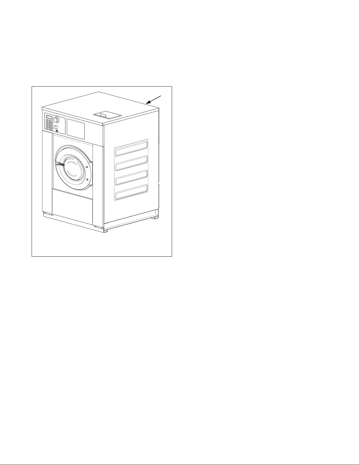
Nameplate Location
The nameplate is located at the rear of the machine.
Always provide the machine’s serial number and
model number when ordering parts or when seeking
technical assistance.
1
Replacement Parts
If literature or replacement parts are required, contact
the source from which the machine was purchased or
contact Alliance Laundry Systems at (920) 748-3950
for the name and address of the nearest authorized
parts distributor.
Customer Service
For technical assistance, call (920) 748-3121.
1 Nameplate
CFD6C
Figure 1
9001001
© Copyright, Alliance Laundry Systems LLC – DO NOT COPY or TRANSMIT
5
Page 8
Introduction
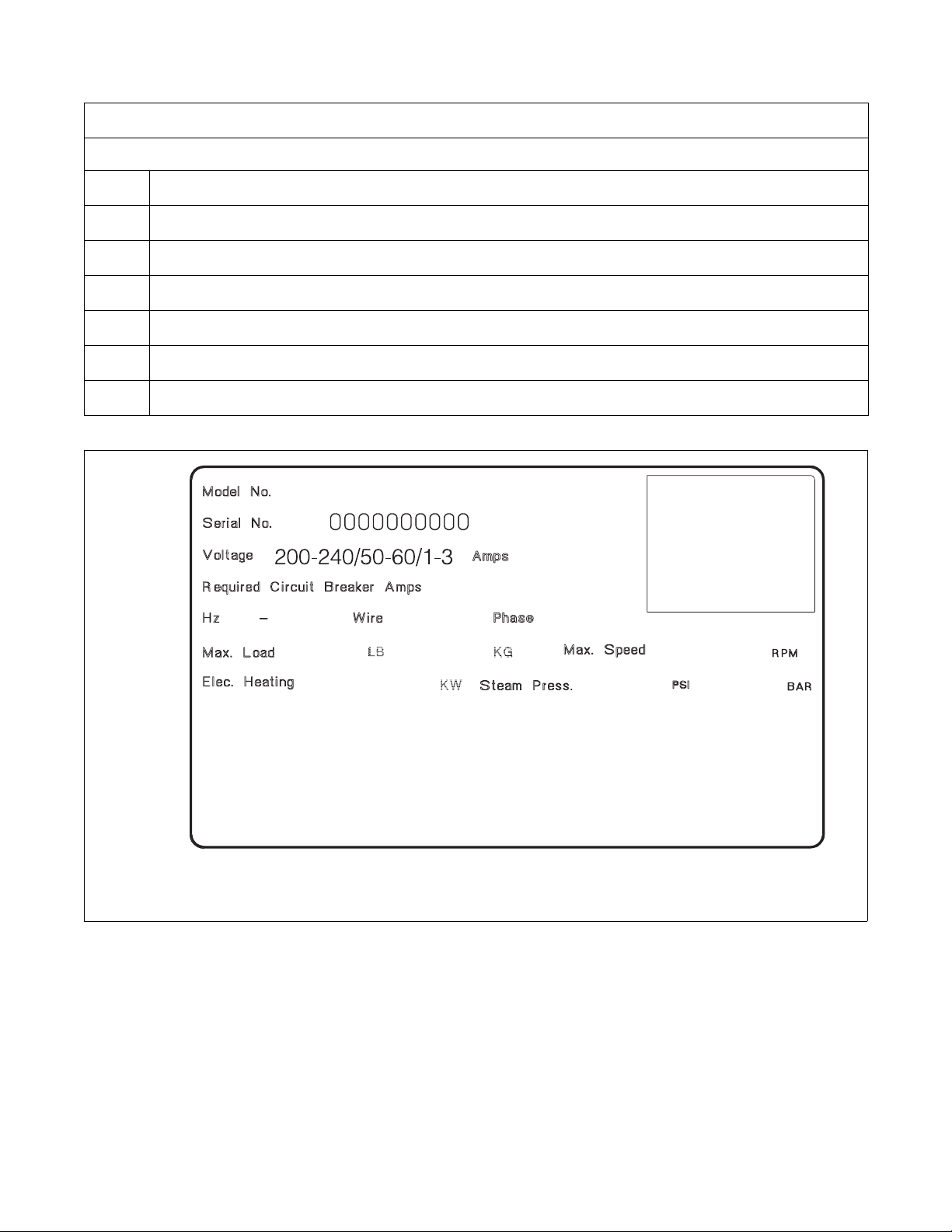
Model Number Familiarization Guide
Sample Model Number: *X55PVXM60001
*X
55
P
V
X
M6
0001
* Denotes Brand
Model Number Prefix
Washer-Extractor Capacity (pounds dry weight of laundry)
Type of Electrical Control (P = WE-6 Computer)
Washer-Extractor Speed Capabilities
Electrical Characteristics
Design Series
Option Identification (varies from machine to machine)
50 60
X55PVXM60001
*
15
2/3+PE 1/3
12
55
25
EXAMPLE OF NAMEPLATE
Figure 2
1000
CFD29N
CFD29N
6
© Copyright, Alliance Laundry Systems LLC – DO NOT COPY or TRANSMIT
9001001
Page 9
Safety Information
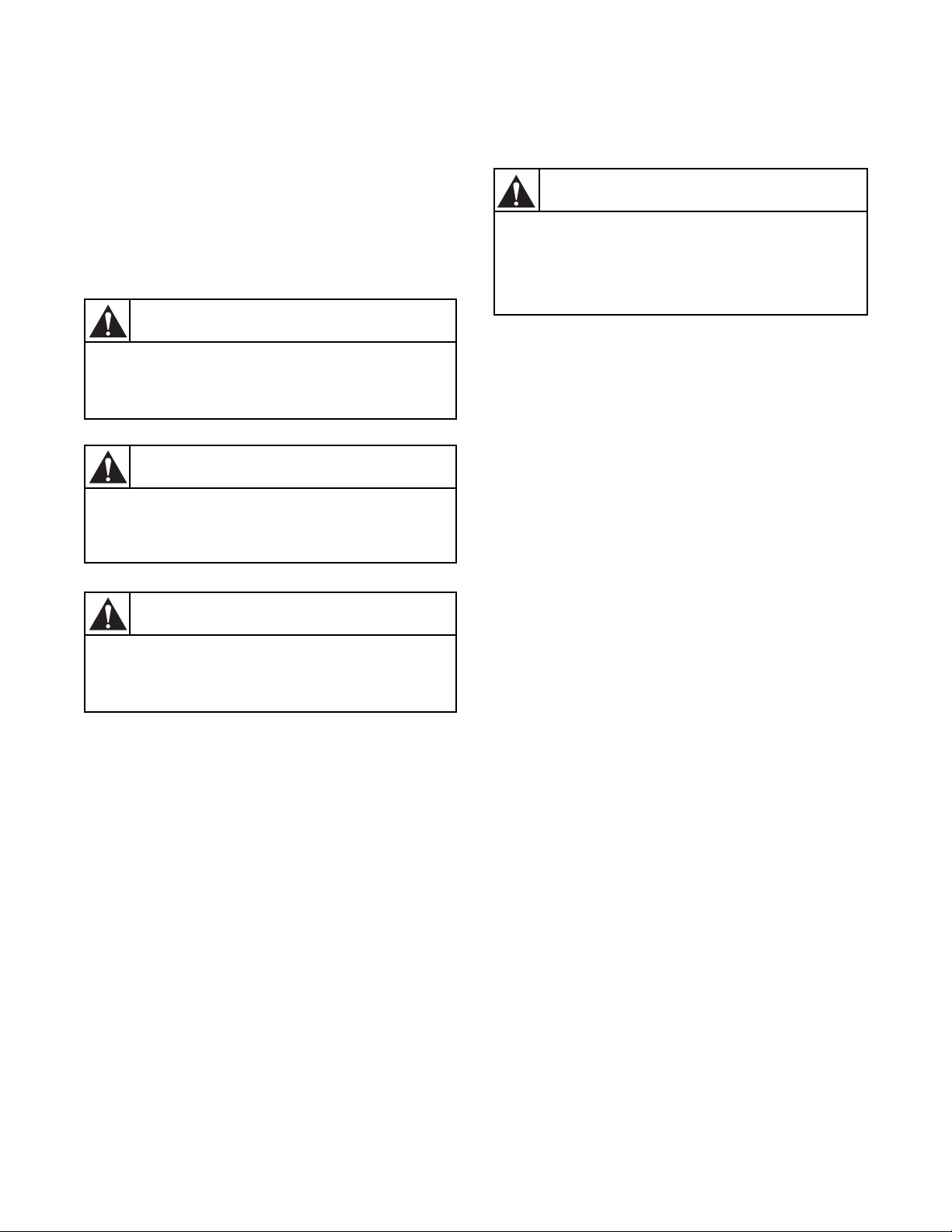
Explanation of Safety Messages
Throughout this manual and on machine decals, you
will find precautionary statements (“DANGER,”
“WARNING,” and “CAUTION”) followed by specific
instructions. These precautions are intended for the
personal safety of the operator, user, servicer, and
those maintaining the machine.
DANGER
Indicates an imminently hazardous
situation that, if not avoided, will cause
severe personal injury or death.
WARNING
Indicates a hazardous situation that, if not
avoided, could cause severe personal
injury or death.
Important Safety Instructions
WARNING
To reduce the risk of fire, electric shock,
serious injury or death to persons when
using your washer, follow these basic
precautions:
W023
1. Read all instructions before using the washer.
2. Refer to the GROUNDING INSTRUCTIONS in
the INSTALLATION manual for the proper
grounding of the washer.
3. Do not wash textiles that have been previously
cleaned in, washed in, soaked in, or spotted with
gasoline, dry-cleaning solvents, or other
flammable or explosive substances as they give
off vapors that could ignite or explode.
4. Do not add gasoline, dry-cleaning solvents, or
other flammable or explosive substances to the
wash water. These substances give off vapors that
could ignite or explode.
CAUTION
Indicates a hazardous situation that, if not
avoided, may cause minor or moderate
personal injury or property damage.
Additional precautionary statements (“IMPORTANT”
and “NOTE”) are followed by specific instructions.
IMPORTANT: The word “IMPORTANT” is used
to inform the reader of specific procedures where
minor machine damage will occur if the procedure
is not followed.
NOTE: The word “NOTE” is used to communicate
installation, operation, maintenance or servicing
information that is important but not hazard
related.
5. Under certain conditions, hydrogen gas may be
produced in a hot water system that has not been
used for two weeks or more. HYDROGEN GAS
IS EXPLOSIVE. If the hot water system has not
been used for such a period, before using a
washing machine or combination washer-dryer,
turn on all hot water faucets and let the water
flow from each for several minutes. This will
release any accumulated hydrogen gas. The gas is
flammable, do not smoke or use an open flame
during this time.
6. Do not allow children to play on or in the washer.
This appliance is not intended for use by young
children or infirm persons without supervision.
Young children should be supervised to ensure
that they do not play with the appliance.
7. Before the washer is removed from service or
discarded, remove the door to the washing
compartment.
8. Do not reach into the washer if the wash drum is
moving.
9001001
© Copyright, Alliance Laundry Systems LLC – DO NOT COPY or TRANSMIT
7
Page 10

Safety Information
9. Do not install or store the washer where it will be
exposed to water and/or weather.
10. Do not tamper with the controls.
11. Do not repair or replace any part of the washer, or
attempt any servicing unless specifically
recommended in the user-maintenance
instructions or in published user-repair
instructions that the user understands and has the
skills to carry out.
12. To reduce the risk of an electric shock or fire, DO
NOT use an extension cord or an adapter to
connect the washer to the electrical power source.
13. Use washer only for its intended purpose,
washing textiles.
14. ALWAYS disconnect the washer from electrical
supply before attempting any service. Disconnect
the power cord by grasping the plug, not the cord.
15. Install the washer according to the
INSTALLATION INSTRUCTIONS. All
connections for water, drain, electrical power and
grounding must comply with local codes and be
made by licensed personnel when required.
16. To reduce the risk of fire, textiles which have
traces of any flammable substances such as
vegetable oil, cooking oil, machine oil,
flammable chemicals, thinner, etc., or anything
containing wax or chemicals such as in mops and
cleaning cloths, must not be put into the washer.
These flammable substances may cause the
fabric to catch on fire by itself.
17. Do not use fabric softeners or products to
eliminate static unless recommended by the
manufacturer of the fabric softener or product.
18. Keep washer in good condition. Bumping or
dropping the washer can damage safety features.
If this occurs, have washer checked by a qualified
service person.
19. Replace worn power cords and/or loose plugs.
20. Be sure water connections have a shut-off valve
and that fill hose connections are tight. CLOSE
the shut-off valves at the end of each wash day.
21. Loading door MUST BE CLOSED any time the
washer is to fill, tumble or spin. DO NOT
bypass the loading door switch by permitting the
washer to operate with the loading door open.
22. Always read and follow manufacturer’s
instructions on packages of laundry and cleaning
aids. Heed all warnings or precautions. To reduce
the risk of poisoning or chemical burns, keep
them out of the reach of children at all times
(preferably in a locked cabinet).
23. Always follow the fabric care instructions
supplied by the textile manufacturer.
24. Never operate the washer with any guards and/or
panels removed.
25. DO NOT operate the washer with missing or
broken parts.
26. DO NOT bypass any safety devices.
27. Failure to install, maintain, and/or operate this
washer according to the manufacturer’s
instructions may result in conditions which can
produce bodily injury and/or property damage.
NOTE: The WARNINGS and IMPORTANT
SAFETY INSTRUCTIONS appearing in this
manual are not meant to cover all possible
conditions and situations that may occur. Common
sense, caution and care must be exercised when
installing, maintaining, or operating the washer.
Any problems or conditions not understood should be
reported to the dealer, distributor, service agent or the
manufacturer.
8
© Copyright, Alliance Laundry Systems LLC – DO NOT COPY or TRANSMIT
9001001
Page 11

Preliminary Information
About the Control
WE-8 computer on the washer-extractor is an
advanced, programmable computer that allows the
owner to create wash programs.
The control is factory set-up with 42 pre-programmed
cycles and is ready for operation. Refer to Pre-
Programmed Cycles section in the Programming
manual.
WE-8 allows the owner to program custom cycles on
the machine or with a PC and the Alliance planner
software.
IMPORTANT: In the event of a power failure,
WE-8 will not have to be reprogrammed. It is
designed with a memory system that will remember
how it was programmed until the electrical power
is restored.
Power Failure Recovery
If a cycle is in process and the power fails, cycle status
is saved in memory without power being applied.
If power resumes, the control will enter into the Start
Mode at the beginning of the cycle step where the
power failed.
9001001
© Copyright, Alliance Laundry Systems LLC – DO NOT COPY or TRANSMIT
9
Page 12

Preliminary Information
Control Identification
1 Keypad 4 Key Switch
2 Display 5 Serial Port
3 Emergency Stop Button
Figure 3
M172
10
© Copyright, Alliance Laundry Systems LLC – DO NOT COPY or TRANSMIT
9001001
Page 13

Operation
Load the Machine
For 18 - 75 models:
Push the black button and pull the door handle towards
you to open the door.
M179A
Figure 4
Load the drum to the specified capacity.
Close the door by pushing the door handle towards the
machine.
M179B
For 100 - 165 models:
Push on the doorlock system to open the door.
CFD63N
Figure 6
Load the drum to the specified capacity.
Close the door by pushing the door handle towards the
machine.
Figure 5
CFD64N
Figure 7
9001001
© Copyright, Alliance Laundry Systems LLC – DO NOT COPY or TRANSMIT
11
Page 14

Operation
Start a Program
No Cycle 23
Please close
Restaurant 2
door
Cycle 00
Cycle 23
After powering up the control, “Cycle 00” will show
on the display.
Press the desired program number
(example: program 23).
The display will show the cycle (example: “Cycle
23”).
Press “Start” to run the program.
If the program does not exist, the display will show
“No Cycle 23”. See program mode to create a
program.
If the door is not closed, the display will show “Please
close door”. After closing the door the program will
start.
If the door is closed and the program exists, the
program will start. The name of the program will show
on the display for 2 seconds and the machine will start.
S01 C23 0:04:59
80°F High
When the machine is started the display will show the
following information.
S01: Step 1
C23: Program number 23
0:04:59: The time of step 1. This will count down to
0 and then go to step 2 (S02).
80°F: The temperature of the bath that is
programmed.
High: The water level in step 1 that is
programmed.
12
© Copyright, Alliance Laundry Systems LLC – DO NOT COPY or TRANSMIT
9001001
Page 15

Special Options in Run Mode
S01 C23 0:04:59
80°F High
Level : 2.5 cm
62°F 40rpm L
S01 C23 0:04:59
80°F High
Operation
While the machine is running press the “Display
Temp” button.
Level: 2.5 cm: Water level in the bath. If the
machine is filling with water this value will
increase. If in a drain step this value will
decrease.
62°F: The water temperature.
40rpm: The measured rpm of the drum.
L: Rotation direction of the drum
L (left), R (right)
Press the “Display Temp” button to go back.
Advance Mode
Press the “Advance” button to proceed to the next step
in the progam.
Chemical Hold Feature
Chemical supply injection can be paused. Refer to
section Setup of the Chemical Hold Feature in
Programming manual.
9001001
© Copyright, Alliance Laundry Systems LLC – DO NOT COPY or TRANSMIT
13
Page 16

Operation
Stop the Machine
S01 C23 0:04:00
Spin 1
Press the Stop button.
Waterlevel
10.2 cm
Coast down
Please open door
Done Cycle 23
If there is water in the machine the display will show
“Waterlevel xx.x cm” while the machine is draining
the water.
If the machine is spinning the display will show
“Coast down”.
When the water is out and the drum has stopped
moving the display will flash between “Please open
door” and “Done cycle 23” until the door is open.
14
© Copyright, Alliance Laundry Systems LLC – DO NOT COPY or TRANSMIT
9001001
Page 17

Error Messages
Operation
Door error
Didn’t fill
within time
Enter to retry
Clear to stop
Done Cycle CC
Please open door
Didn’t fill
within time
Door Error
If the door is closed after start the control will try to
lock the door. If the door will not lock “Door error”
will display.
Possible Faults:
● Wiring is not connected properly.
● Coil to lock the door has failed.
● Mechanical problem on the door lock.
Fill Alarm
If machine does not reach programmed water level
within time programmed for step, a fill alarm occurs.
Machine will continue filling and agitating, while
sounding beeper and flashing “Didn’t fill within time”
on display.
Condition will continue for up to two (2) minutes. If
programmed water level is reached before two minute
fill alarm time ends, condition ends, and machine
resumes operation. If Enter key is pressed during fill
alarm, condition will end and step will start over. If
programmed water level is not reached within
programmed step time, fill alarm will occur again. If
Clear (STOP) key is pressed while fill alarm is in
effect, cycle will end, and door will unlock. If no
action is taken, and fill level is not reached within
two minute alarm time limit, cycle will end and door
can be unlocked (provided no water level is sensed).
Whenever a fill alarm occurred during a cycle, display
will repeat following messages at end of stop routine,
before door is opened, to indicate alarm condition
occurred in cycle.
9001001
During step N
(CC = cycle number;
N = step number in which the
alarm occurred).
© Copyright, Alliance Laundry Systems LLC – DO NOT COPY or TRANSMIT
15
Page 18

Operation
Didn’t drain
within time
Enter to retry
Clear to stop
Fill Alarm (Continued)
Possible Faults:
● Wiring is not connected properly to the inlet
valves.
● The inlet valve is broken.
● There is a problem with the water supply.
● The inlet valves are blocked by dirt.
● The water pressure hose is broken or not
connected properly.
Drain Alarm
If drain step is NOT followed by a spin and if machine
does not empty within the time programmed for drain
step, a drain alarm occurs. Display will read “Didn’t
drain within time.”
Done Cycle CC
Please open door
Didn’t drain
within time
During step N
(CC = cycle number;
N = step number in which the
alarm occurred).
During drain alarm, beeper sounds on and off, and
machine continues attempting to drain. If machine
does not empty, condition continues. If Enter key is
pressed, drain alarm ends, and drain step starts over at
beginning. If machine has not emptied when drain step
time expires, alarm occurs again. If Clear (STOP) key
is pressed while drain alarm is in effect, display shows
water level (inches or centimeters), but otherwise takes
no new action since machine has not emptied.
When cycle ends, display repeats following messages
briefly until door is opened (to indicate that an alarm
condition occurred in the cycle):
If machine drains during a spin step prior to
accelerating into high speed and if machine has not
emptied within approximately 2 minutes of starting
drain procedure, a drain alarm occurs. There is no
rotation during this alarm; messages displayed are
identical to drain alarm during a drain step not
followed by a spin. Pressing Enter (START) during
drain alarm in a spin step ends alarm and begins spin
step again at start, with machine rotating at wash speed
forward, then to distribution speed. After drain begins
(i.e., drain open, pumping begins), if 2 additional
minutes elapse, alarm occurs again.
16
© Copyright, Alliance Laundry Systems LLC – DO NOT COPY or TRANSMIT
9001001
Page 19

Operation
Temperature
sensor error
Rotation
sensor error
If there was a problem during heating in a step at the
end of the program, the control will show
“Temperature sensor error”. The temperature was
never reached in this cycle.
Possible Faults:
● Bad temperature probe.
● Wiring to electrical or steam heating relay has
failed.
● Electrical heating elements or steam valve is
broken.
NOTE: If the cycle aborted, it may be due to a
temperature sensor error.
The control did not sense any pulses or the control
sensed wrong pulses from the rpm sensor.
Possible Faults:
● Rpm sensor is broken.
● Distance from rpm sensor to pulley is too large
(>2mm).
Speed detection
error
● Bad motor.
● V-belt is broken.
● Problems with the inverter.
● Wiring connection is bad.
An error occurred at the end of a spin stop or during
coast down, where the rpm sensor suddenly failed to
give output pulses.
Possible Faults:
● Rpm sensor failure.
● Rpm sensor dislocated (too far from pulley).
● Broken V-belt.
● Wiring disconnected.
9001001
© Copyright, Alliance Laundry Systems LLC – DO NOT COPY or TRANSMIT
17
Page 20

Notes
18
© Copyright, Alliance Laundry Systems LLC – DO NOT COPY or TRANSMIT 9001001
Page 21

Maintenance
Routine maintenance maximizes operating efficiency
and minimizes downtime. The maintenance
procedures described below will prolong the life of the
machine and help prevent accidents.
CAUTION
Replace all panels that are removed to
perform service and maintenance
procedures. Do not operate the machine
with missing guards or with broken or
missing parts. Do not bypass any safety
devices.
SW019
Daily, weekly, monthly, and yearly checklists are
provided at the end of this section. Laminate the
checklists to preserve them for repeated copying.
Operators and technicians are encouraged to add
checks specific to their machine’s particular
application. When possible, space is provided on the
checklists for this purpose.
The following maintenance procedures must be
performed regularly at the required intervals.
Daily
Beginning of the day
1. Inspect water inlet valve hose connections on the
back of the machine for leaks.
2. Inspect steam hose connections for leaks, where
applicable.
3. Verify that insulation is intact on all external
wires and that all connections are secure. If bare
wire is evident, call a service technician.
4. Check door interlock before starting operation:
a. Attempt to start the washer with the door
open. The washer should not start with the
door open.
b. Close the door and start the machine. Attempt
to open the door while the cycle is in progress.
The door should not open.
IMPORTANT: If the door lock and interlock are
not functioning properly, take machine out of
service. Call a service technician to correct.
9001001
© Copyright, Alliance Laundry Systems LLC – DO NOT COPY or TRANSMIT
19
Page 22

Maintenance
End of day
1. Clean the fan of the AC drive box.
2. Clean the entire cabinet of the machine regularly
and remove all traces of soap, etc.
3. Remove all detergent residue in the soap
dispenser with hot water.
4. Clean the door gasket and remove all detergents
and other products.
5. Shut off the main water, steam and power
connections at the end of each day. Do not
change the setting of the water inlet taps on boiler
fed machines once these have been installed.
6. It is recommended to leave the door and the soap
dispenser open after use, to ventilate the
machine.
NOTE: Unload the machine promptly after each
completed cycle to prevent moisture buildup. Leave
loading door open at the end of each completed
cycle to allow moisture to evaporate.
Weekly
1. Check the machine for leaks.
a. Start an unloaded cycle to fill the machine.
b. Verify that door and door gasket do not leak.
c. Verify that the drain valve is operating. If
water does not leak out during the prewash
segment, drain valve is closed and functioning
properly.
Monthly
NOTE: Disconnect power to the machine at its
source before performing the monthly maintenance
procedures.
1. Clean the AC drive Box.
a. Remove the AC drive box cover.
b. Blow the fins clean using compressed air at a
pressure of 60-90 psi or by using canned
compressed air. Use care to avoid damaging
cooling fan or other components.
2. V-belts.
a. Check V-belts for uneven wear and frayed
edges.
b. Verify that V-belts are properly aligned by
checking pulley alignment. Place a
straightedge across both pulley faces. The
straightedge should make contact with the
pulleys in four places.
20
© Copyright, Alliance Laundry Systems LLC – DO NOT COPY or TRANSMIT
9001001
Page 23

Maintenance
3. Remove back panel and check overflow hose and
drain hose for leaks.
4. Clean inlet hose filter screen:
a. Turn water off and allow valve to cool, if
necessary.
b. Unscrew inlet hose and remove filter screen.
c. Clean with soapy water, rinse and reinstall.
Replace if worn or damaged.
5. Check the supply dispenser hoses for leaks.
6. Use compressed air to clean lint from motor.
7. Clean interior of machine, both basket and shell,
by wiping with a water-soaked sponge or cloth.
8. Use compressed air to ensure that all electrical
components are free of moisture and dust.
Yearly
1. Replace the automatic lubricator (only for 75100-135-165 machine). Failure to do so could
void the warranty.
2. Check if the machine is working properly. If you
see or hear any abnormal function on the
machine call a service technician.
9001001
© Copyright, Alliance Laundry Systems LLC – DO NOT COPY or TRANSMIT
21
Page 24

Maintenance
Daily Preventive Maintenance
Checklist
Machine ____________________________
Operator ___________________________
Checks 1234567
Beginning of Day
1. Inspect water inlet valve hose connections on the back of the
machine for leaks.
2. Inspect steam hose connections for leaks, where applicable.
3. Verify that insulation is intact on all external wires and that all
connections are secure.
4. Inspect door lock and interlock before starting operation:
a. Attempt to start the machine with door open.
b. Close the door and start the machine. Attempt to open the door
while the cycle is in progress.
5.
End of Day
1. Clean the fan of the AC drive box.
Week of: ________________
Days
2. Clean the entire cabinet of the machine.
3. Remove all detergent residue in the soap dispenser with hot water.
4. Clean the door gasket and remove all detergents and other products.
5. Shut off the main water, steam and power.
6. Leave loading door open at the end of each day to ventilate the
machine.
7.
NOTE: Unload the machine promptly after each completed cycle to prevent moisture buildup.
NOTE: Leave loading door open after each completed cycle to allow moisture to evaporate.
22
© Copyright, Alliance Laundry Systems LLC – DO NOT COPY or TRANSMIT
9001001
Page 25

Weekly Preventive Maintenance
Checklist
Maintenance
Machine ____________________________
Operator ___________________________
Checks /////
1. Check the machine for leaks:
a. Start an unloaded cycle to fill the machine.
b. Verify that door and door gasket do not leak.
c. Verify that the drain valve is operating.
2.
3.
4.
5.
6.
7.
Month __________
Week Ending:
9001001
© Copyright, Alliance Laundry Systems LLC – DO NOT COPY or TRANSMIT
23
Page 26

Maintenance
Monthly Preventive Maintenance
Checklist
Machine ____________________________
Operator ___________________________
Checks
Observe All Safety Warnings!
Disconnect power to the machine before performing the monthly maintenance procedures.
1. Clean the AC drive box.
2. V-belts
a. Check V-belts for uneven wear and frayed edges.
b. Verify that V-belts are properly aligned by checking pulley alignment.
3. Remove back panel and check overflow hose and drain hose for leaks.
4. Clean inlet hose filter screen.
5. Check the supply dispenser hoses for leaks.
6. Use compressed air to clean lint from motor.
7. Clean interior of machine, both basket and shell, by wiping with a water-soaked
sponge or cloth.
Month
8. Use compressed air to ensure that all electrical components are free of moisture and
dust.
9.
10.
24
© Copyright, Alliance Laundry Systems LLC – DO NOT COPY or TRANSMIT
9001001
Page 27

Yearly Preventive Maintenance
Checklist
Maintenance
Machine ____________________________
Operator ___________________________
Checks
Observe All Safety Warnings!
Disconnect power to the machine before performing the quarterly maintenance procedures.
1. Replace the automatic lubricator (only for 75-100-135-165 machines).
2. Check if the machine is working properly. If you see or hear any abnormal function
on the machine call a service technician.
3.
4.
5.
6.
7.
8.
Year
9.
9001001
© Copyright, Alliance Laundry Systems LLC – DO NOT COPY or TRANSMIT
25
Page 28

 Loading...