

Alliance Laundry Systems CP040PMN1, CPC40M, CP040PMQ1, CP040PMX2, IP040PMN1 Installation Operation & Maintenance
...Page 1
Washer-Extractors
PHM1397C
PHM1397C
Pocket Hardmount Variable-Speed
Refer to Page 6 for Model Identification
Installation/Operation/Maintenance
Original Instructions
Keep These Instructions for Future Reference.
(If this machine changes ownership, this manual must accompany machine.)
www.alliancelaundry.com
Part No. C003292ENR1
November 2013
Page 2

Page 3

Table of
Contents
Safety Information.............................................................................. 3
Explanation of Safety Messages........................................................... 3
Important Safety Instructions ............................................................... 3
Safety Decals ........................................................................................ 5
Operator Safety..................................................................................... 5
Model Identification ............................................................................. 6
Introduction......................................................................................... 7
Delivery Inspection............................................................................... 7
Nameplate Location.............................................................................. 7
Replacement Parts ................................................................................ 7
Customer Service.................................................................................. 7
Specifications and Dimensions........................................................... 8
High Speed Models............................................................................... 8
Medium Speed Models......................................................................... 10
Machine Dimensions ............................................................................ 12
40 Pound Models ............................................................................ 13
60 Pound Models ............................................................................ 14
80 Pound Models ............................................................................. 15
100 Pound Models ........................................................................... 16
125 Pound Models ........................................................................... 17
140 Pound Models ........................................................................... 18
175 Pound Models ........................................................................... 19
Floor Load Data.................................................................................... 20
Installation Instructions ........................................................................ 21
Surface ............................................................................................. 21
Anchors ............................................................................................ 21
Mounting.......................................................................................... 21
Mounting Bolt Installation Requirements ............................................ 21
Location ........................................................................................... 21
Clearances ........................................................................................ 22
Mounting Bolt Hole Locations ............................................................. 23
Installing Anchors............................................................................ 23
Grouting and Setting Machine ......................................................... 23
Mounting Bolt Hole Locations ............................................................. 24
40 Pound Models ............................................................................. 24
60, 80 and 100 Pound Models.......................................................... 26
125, 140 and 175 Pound Models...................................................... 28
Water Connection ................................................................................. 30
Drain Connection Requirements........................................................... 31
Electrical Installation Requirements..................................................... 33
Circuit Breakers ............................................................................... 34
Grounding ........................................................................................ 34
Wire Size.......................................................................................... 34
Making Connections to Machine..................................................... 36
Adjusting Control Transformer Taps............................................... 36
Provisions for 50 Hz Installations.................................................... 36
Steam Requirements (Steam Heat Option Only).................................. 37
Chemical Injection Supply System....................................................... 38
© Copyright 2013, Alliance Laundry Systems LLC
All rights reserved. No part of the contents of this book may be reproduced or transmitted in any form or by any
means without the expressed written consent of the publisher.
C003292ENR1
© Copyright, Alliance Laundry Systems LLC – DO NOT COPY or TRANSMIT
1
Page 4

Chemical Service Connections ........................................................ 38
Connection of Chemical Supply Hoses ........................................... 38
Connection of Chemical Pump Signals ........................................... 39
First Start-Up ...................................................................................... 40
Operation............................................................................................. 41
General Operation Instructions............................................................. 41
Maintenance ........................................................................................ 43
Daily ..................................................................................................... 43
Beginning of Day............................................................................. 43
End of Day ....................................................................................... 43
Weekly.................................................................................................. 44
Monthly................................................................................................. 44
Quarterly ............................................................................................... 45
Care of Stainless Steel .......................................................................... 46
Disposal of Unit................................................................................... 47
2
© Copyright, Alliance Laundry Systems LLC – DO NOT COPY or TRANSMIT
C003292ENR1
Page 5
Safety Information
DANGER indicates an imminently
hazardous situation that, if not avoided,
will cause severe personal injury or
death.
DANGER
WARNING indicates a hazardous situation
that, if not avoided, could cause severe
personal injury or death.
WARNING
CAUTION indicates a hazardous situation
that, if not avoided, may cause minor or
moderate personal injury or property
damage.
CAUTION
To reduce the risk of fire, electric shock,
serious injury or death to persons when
using your washer, follow these basic
precautions:
W023
WARNING
Explanation of Safety Messages
Precautionary statements (“DANGER,” “WARNING,”
and “CAUTION”), followed by specific instructions,
are found in this manual and on machine decals. These
precautions are intended for the personal safety of the
operator, user, servicer, and those maintaining the
machine.
Additional precautionary statements (“IMPORTANT”
and “NOTE”) are followed by specific instructions.
IMPORTANT: The word “IMPORTANT” is used
to inform the reader of specific procedures where
minor machine damage will occur if the procedure
is not followed.
NOTE: The word “NOTE” is used to communicate
installation, operation, maintenance or servicing
information that is important but not hazard
related.
Important Safety Instructions
1. Read all instructions before using the washer.
2. Install the washer according the
INSTALLATION instructions. Refer to the
GROUNDING instructions in the
INSTALLATION manual for the proper
grounding of the washer. All connections for
water, drain, electrical power and grounding must
comply with local codes and be made by licensed
personnel when required. It is recommended that
the machine be installed by qualified technicians.
3. Do not install or store the washer where it will be
exposed to water and/or weather.
4. To prevent fire and explosion, keep the area
around machine free from flammable and
combustible products. Do not add the following
substances or textiles containing traces of the
following substances to the wash water: gasoline,
kerosene, waxes, cooking oils, vegetable oils,
machine oils, dry-cleaning solvents, flammable
chemicals, thinners, or other flammable or
explosive substances. These substances give off
vapors that could ignite, explode or cause the
fabric to catch fire by itself.
5. Under certain conditions, hydrogen gas may be
produced in a hot water system that has not been
used for two weeks or more. HYDROGEN GAS
IS EXPLOSIVE. If the hot water system has not
been used for such a period, before using a
washing machine or combination washer-dryer,
turn on all hot water faucets and let the water
flow from each for several minutes. This will
release any accumulated hydrogen gas. The gas
is flammable, do not smoke or use an open flame
during this time.
C003292ENR1
© Copyright, Alliance Laundry Systems LLC - DO NOT COPY or TRANSMIT
6. To reduce the risk of an electric shock or fire, DO
NOT use an extension cord or an adapter to
connect the washer to the electrical power
source.
3
Page 6

Safety Information
7. Do not allow children to play on or in the washer.
Close supervision of children is necessary when
the washer is used near children. This appliance
is not intended for use by young children or
infirm persons without supervision. Young
children should be supervised to ensure that they
do not play with the appliance. This is a safety
rule for all appliances.
8. DO NOT reach and/or climb into the tub or onto
the washer, ESPECIALLY if the wash drum is
moving. This is an imminently hazardous
situation that, if not avoided, will cause severe
personal injury or death.
9. Never operate the washer with any guards, panels
and/or parts removed or broken. DO NOT bypass
any safety devices or tamper with the controls.
10. Use washer only for its intended purpose,
washing textiles. Never wash machine parts or
automotive parts in the machine. This could
result in serious damage to the basket or tub.
11. Use only low-sudsing, no-foaming types of
commercial detergent. Be aware that hazardous
chemicals may be present. Wear hand and eye
protection when adding detergents and
chemicals. Always read and follow
manufacturer’s instructions on packages of
laundry and cleaning aids. Heed all warnings or
precautions. To reduce the risk of poisoning or
chemical burns, keep them out of the reach of
children at all times (preferably in a locked
cabinet).
12. Do not use fabric softeners or products to
eliminate static unless recommended by the
manufacturer of the fabric softener or product.
13. Always follow the fabric care instructions
supplied by the textile manufacturer.
14. Loading door MUST BE CLOSED any time the
washer is to fill, tumble or spin. DO NOT bypass
the loading door switch by permitting the washer
to operate with the loading door open. Do not
attempt to open the door until the washer has
drained and all moving parts have stopped.
15. Be aware that hot water is used to flush the
supply dispenser. Avoid opening the dispenser lid
while the machine is running.
16. Do not attach anything to the supply dispenser’s
nozzles, if applicable. The air gap must be
maintained.
18. Be sure water connections have a shut-off valve
and that fill hose connections are tight. CLOSE
the shut-off valves at the end of each wash day.
19. Keep washer in good condition. Bumping or
dropping the washer can damage safety features.
If this occurs, have washer checked by a
qualified service person.
20. DANGER: Before inspecting or servicing
machine, power supply must be turned OFF. The
servicer needs to wait for at least 3 minutes after
turning the power OFF and needs to check for
residual voltage with a voltage meter. The
inverter capacitor or EMC filter remains charged
with high voltage for some time after powering
OFF. This is an imminently hazardous situation
that, if not avoided, will cause severe personal
injury or death.
21. Do not repair or replace any part of the washer, or
attempt any servicing unless specifically
recommended in the user-maintenance
instructions or in published user-repair
instructions that the user understands and has the
skills to carry out. ALWAYS disconnect the
washer from electrical, power and water supplies
before attempting any service.
22. Disconnect the power cord by grasping the plug,
not the cord. Replace worn power cords and/or
loose plugs. If the supply cord is damaged, it
must be replaced by a special cord or assembly
available from the service agent.
23. Before the washer is removed from service or
discarded, remove the door to the washing
compartment.
24. Failure to install, maintain, and/or operate this
washer according to the manufacturer’s
instructions may result in conditions which can
produce bodily injury and/or property damage.
NOTE: The WARNINGS and IMPORTANT
SAFETY INSTRUCTIONS appearing in this
manual are not meant to cover all possible
conditions and situations that may occur. Common
sense, caution and care must be exercised when
installing, maintaining, or operating the washer.
Any problems or conditions not understood should be
reported to the dealer, distributor, service agent or the
manufacturer.
17. Do not operate the machine without the water
reuse plug or water reuse system in place, if
applicable.
4
© Copyright, Alliance Laundry Systems LLC - DO NOT COPY or TRANSMIT
C003292ENR1
Page 7
IMPORTANT: Ensure that the recommended
Machine installations must comply with
minimum specifications and
requirements stated in the applicable
Installation Manual, any applicable
municipal building codes, water supply
requirements, electrical wiring
regulations and any other relevant
statutory regulations. Due to varied
requirements and applicable local codes,
this machine must be installed, adjusted,
and serviced by qualified maintenance
personnel familiar with applicable local
codes and the construction and operation
of this type of machinery. They must also
be familiar with the potential hazards
involved. Failure to observe this warning
may result in personal injury, property
damage, and/or equipment damage, and
will void the warranty.
W820
WARNING
Never touch internal or external steam
pipes, connections, or components.
These surfaces can be extremely hot and
will cause severe burns. The steam must
be turned off and the pipe, connections,
and components allowed to cool before
the pipe can be touched.
SW014
WARNING
NEVER insert hands or objects into
basket until it has completely stopped.
Doing so could result in serious injury.
SW012
WARNING
Operating the machine with severe out-ofbalance loads could result in personal
injury and serious equipment damage.
W728
WARNING
clearances for inspection and maintenance are
provided. Never allow the inspection and
maintenance space to be blocked.
Safety Information
Operator Safety
The following maintenance checks must be performed
daily:
1. Verify that all warning signs are present and
legible, replace as necessary.
2. Check door interlock before starting operation of
machine:
a. Attempt to start machine with door open.
Machine should not start.
b. Close door without locking it and attempt to
start machine. Machine should not start.
c. Attempt to open door while the cycle is in
progress. The door should not open.
If door lock and interlock are not functioning
properly, disconnect power and call a service
technician.
3. Do not attempt to operate machine if any of the
following conditions are present:
Safety Decals
Safety decals appear at crucial locations on the
machine. Failure to maintain legible safety decals
could result in injury to the operator or service
technician.
Use manufacturer-authorized spare parts to avoid
safety hazards.
C003292ENR1
© Copyright, Alliance Laundry Systems LLC - DO NOT COPY or TRANSMIT
a. Door does not remain securely locked during
entire cycle.
b. Excessively high water level is evident.
c. Machine is not connected to a properly
grounded circuit.
Do not bypass any safety devices in machine.
5
Page 8

Safety Information
Model Identification
Information in this manual is applicable to these models:
Medium Speed High Speed
IP040PMQ1
IP040PMX2
IPH40M
IPH180
IPH270
JP060PMQ1
IP080PMQ1
IP080PMQ2
IPH80M
IPH370
IP100PMQ1
IPH100M
IPH460
JP100PMQ1
IP140PMQ1
IPH140M
IPH640
JP140PMQ1
40
Pound
60
Pound
80
Pound
100
Pound
125
Pound
140
Pound
175
Pound
CP040PMN1
CP040PMQ1
CP040PMX2
CPC40M
IP040PMN1
IP040PMN2
CP060PMN1
CP060PMQ1
CP060PMX2
CPC60M
IP060PMN1
IP060PMQ1
IP060PMX2
IPH60M
CP080PMN1
CP080PMN2
CP080PMQ1
CPC80M
IP080PMN1
IP080PMN2
CP100PMN1
CP100PMN2
CP100PMQ1
CPC100M
IP100PMN1
IP100PMN2
Not Applicable
CP140PMN1
CP140PMQ1
CPC140M
IP140PMN1
Not Applicable
CP040PHN1
CP040PHQ1
CP040PHX2
CPC40H
IP040PHN1
IP040PHN2
CP060PHN1
CP060PHN2
CP060PHQ1
CP060PHQ2
CP060PHX1
CP060PHX2
CPC60H
IP060PHN1
CP080PHN1
CP080PHN2
CP080PHQ1
CP080PHQ2
CPC80H
IP080PHN1
CP100PHN1
CP100PHN2
CP100PHQ1
CP100PHQ2
CPC100H
IP100PHN1
CP125PHN1
CP125PHN2
CP125PHQ1
CP125PHQ2
CPC125H
IP125PHN1
IP125PHN2
CP140PHN1
CP140PHQ1
CPC140H
IP140PHN1
CP175PHN1
CPC175H
IP175PHN1
IPH175H
IP040PHQ1
IP040PHX2
IPH40H
JP040PHN1
JP040PHQ1
IP060PHN2
IP060PHQ1
IP060PHX2
IPH60H
JP060PHN1
JP060PHN2
JP060PHQ1
IP080PHN2
IP080PHQ1
IPH80H
JP080PHN1
JP080PHN2
JP080PHQ1
IP100PHN2
IP100PHQ1
IPH100H
JP100PHN1
JP100PHN2
JP100PHQ1
IP125PHQ1
IP125PHQ2
IPH125H
IPH570
JP125PHN1
JP125PHN2
IP140PHQ1
IPH140H
JP140PHN1
JP140PHQ1
IPH790
JP175PHN1
JP175PHN2
6
© Copyright, Alliance Laundry Systems LLC - DO NOT COPY or TRANSMIT
C003292ENR1
Page 9
Introduction
PHM1397C
1
2
Delivery Inspection
Upon delivery, visually inspect crate, protective cover
and unit for any visible shipping damage. If the crate,
protective cover or unit is damaged or signs of
possible damage are evident, have the carrier note the
condition on the shipping papers before the shipping
receipt is signed or advise the carrier of the condition
as soon as it is discovered.
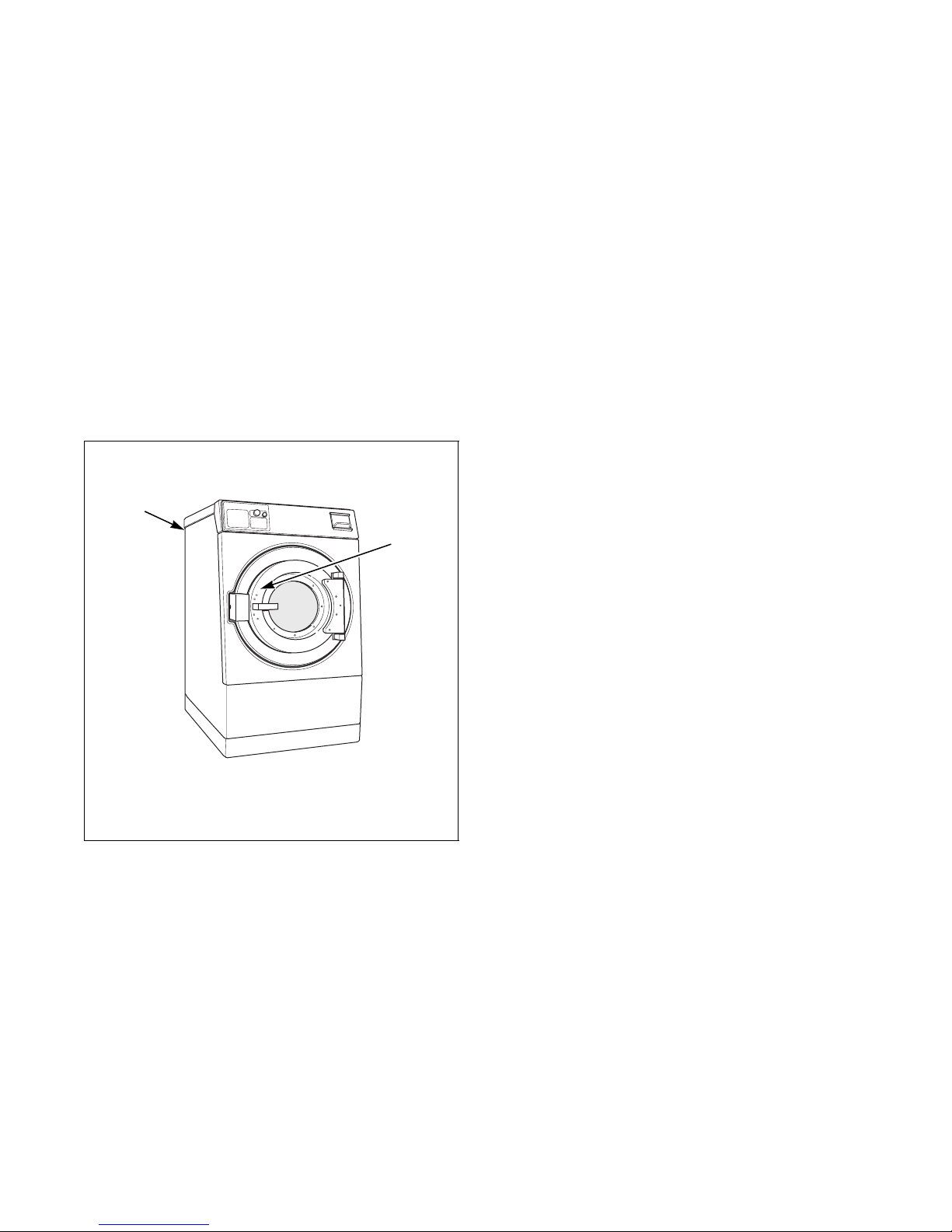
Nameplate Location
The nameplate is located inside the door and on the
upper rear panel. Always provide the machine’s serial
number and model number when ordering parts or
when seeking technical assistance. Refer to Figure 1.
Replacement Parts
If literature or replacement parts are required, contact
the source from which the machine was purchased or
contact Alliance Laundry Systems LLC at
+1 (920) 748-3950 for the name of the nearest
authorized parts distributor.
Customer Service
For technical assistance, contact your local distributor
or contact:
Alliance Laundry Systems
Shepard Street
P. O . B ox 99 0
Ripon, WI 54971-0990
U.S.A.
www.alliancelaundry.com
Phone: +1 (920) 748-3121 Ripon, Wisconsin
+32 56 41 20 54 Wevelgem, Belgium
1 Inside the Door
2 On Upper Rear Panel
Figure 1
C003292ENR1
© Copyright, Alliance Laundry Systems LLC - DO NOT COPY or TRANSMIT
PHM1397N
7
Page 10
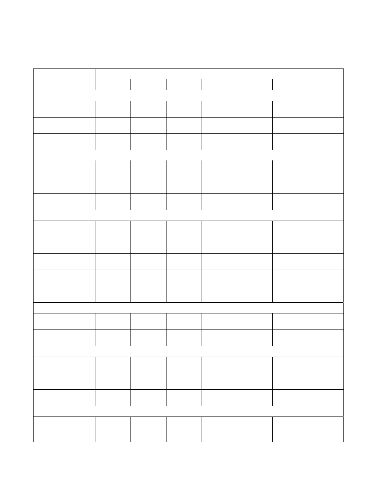
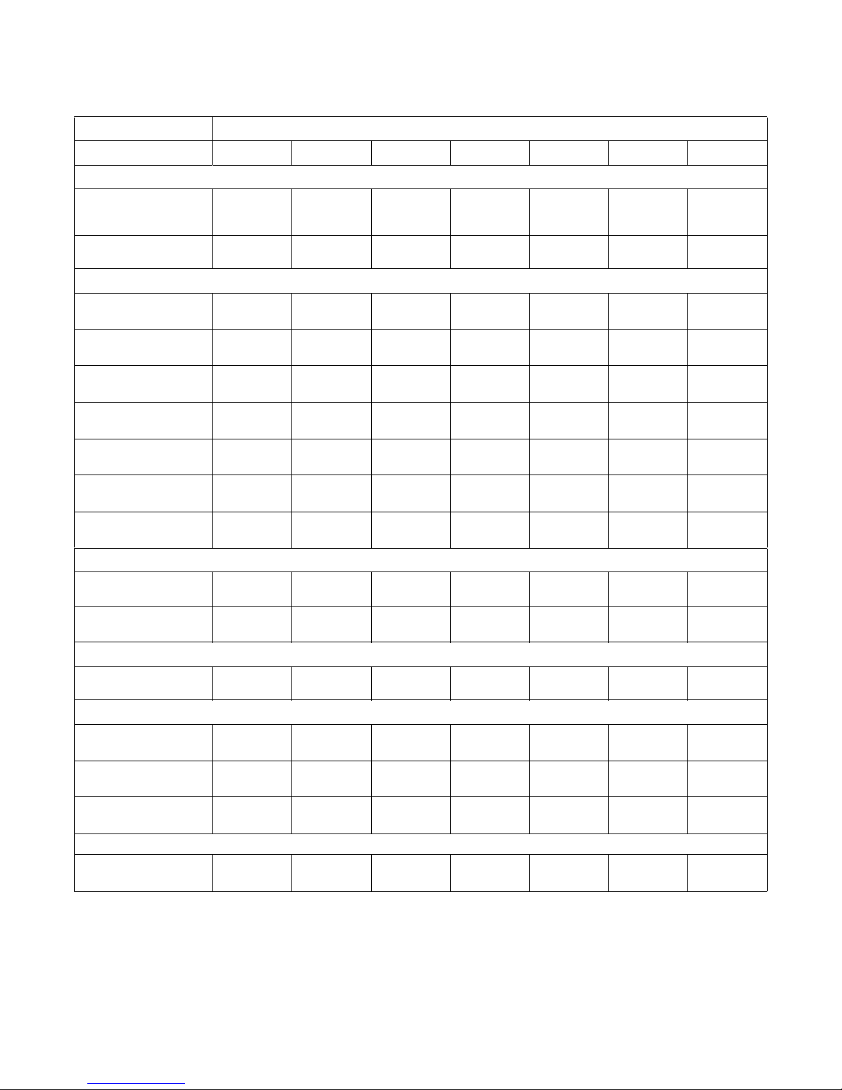
Specifications and Dimensions
High Speed Models
Models
Specifications 40H 60H 80H 100H 125H 140H 175H
Overall Dimensions
Overall Width,
in. (mm)
Overall Height,
in. (mm)
Overall Depth,
in. (mm)
Weight and Shipping Information
Net Weight,
lbs. (kg)
Domestic Shipping
Weight, lbs. (kg)
Domestic Shipping
Volume , f t
3
(m3)
Wash Cylinder Information
Cylinder Diameter,
in. (mm)
Cylinder Depth,
in. (mm)
Cylinder Volume,
ft3 (l)
Perforation Size,
in. (mm)
Cylinder Capacity 1:10
Fill Ratio, lbs. (kg)
32
(813)
57
(1448)
45.6
(1158)
1093
(496)
1150
(522)
63
(1.78)
27
(686)
19
(483)
6.3
(178.4)
0.19
(4.83)
39.3
(17.8)
34.5
(876)
62.6
(1590)
47.8
(1214)
1367
(620)
1424
(646)
76.9
(2.18)
31
(787)
22
(559)
9.6
(271.8)
0.19
(4.83)
60
(27.2)
42.5
(1080)
70
(1778)
51.4
(1306)
1908
(865)
2001
(908)
110
(3.11)
37
(940)
21
(533)
13.1
(371.0)
0.19
(4.83)
81.6
(37)
42.5
(1080)
70
(1778)
56.4
(1433)
1979
(898)
2072
(940)
122
(3.45)
37
(940)
26
(660)
16.2
(458.7)
0.19
(4.83)
101
(45.8)
50.3
(1278)
77.1
(1958)
56.1
(1425)
2459
(1115)
2557
(1160)
160
(4.53)
43
(1092)
24
(610)
20.1
(569.2)
0.19
(4.83)
125
(56.7)
50.3
(1278)
77.1
(1958)
59.1
(1501)
2725
(1236)
2823
(1280)
167
(4.73)
43
(1092)
27
(686)
22.7
(642.8)
0.19
(4.83)
141.7
(64.3)
50.3
(1278)
77.1
(1958)
64.1
(1628)
2963
(1344)
3064
(1390)
179
(5.07)
43
(1092)
32
(813)
26.8
(758.9)
0.19
(4.83)
175
(79.4)
Door Opening Information
Door Opening Size,
in. (mm)
Height of Door Bottom
Above Floor, in. (mm)
15
(381)
22.5
(572)
Drain System
Overflow Size,
in. (mm)
Drain Outlet Size,
in. (mm)
Number of Drain Outlets,
(std/opt)
1.5
(38.1)
3
(76.2)
1/2 1/2 1/2 1/2 1/2 1/2 1/2
Water Inlet
Connection Size
Number of Inlets,
(std/opt)
8
3/4 NPT 3/4 NPT 3/4 NPT 3/4 NPT 3/4 NPT 1-1/4 NPT 1-1/4 NPT
2/3 2/3 2/3 2/3 2/3 2/3 2/3
© Copyright, Alliance Laundry Systems LLC - DO NOT COPY or TRANSMIT
17
(432)
25.8
(655)
1.5
(38.1)
3
(76.2)
20
(508)
26.6
(676)
1.5
(38.1)
3
(76.2)
Table 1 (continued)
20
(508)
27.1
(688)
1.5
(38.1)
3
(76.2)
24.5
(622)
31.3
(795)
3
(76.2)
3
(76.2)
24.5
(622)
31.3
(795)
3
(76.2)
3
(76.2)
24.5
(622)
31.3
(795)
3
(76.2)
3
(76.2)
C003292ENR1
Page 11
Specifications and Dimensions
Table 1 (continued)
Models
Specifications 40H 60H 80H 100H 125H 140H 175H
Chemical Supply System
Number of Dry Chemical
Compartments,
(std/opt)
Number of Liquid Supply
Connections, (std/opt)
1/5 1/5 1/5 1/5 1/5 1/5 1/5
6/12 6/12 6/12 6/12 6/12 6/12 6/12
Cylinder Speeds/Centrifugal Force Data
Possible Wash Speeds,
RPM (G-Force)
Preset Wash Speed,
RPM (G-Force)
Balance Speed,
RPM (G-Force)
Preset Low Extract
Speed, RPM (G-Force)
Preset Medium Extract
Speed, RPM (G-Force)
Preset High Extract
Speed, RPM (G-Force)
Maximum SmartSpin
Speed, RPM (G-Force)
10-60
(0.05-1.4)
46
(0.8)
81
(2.5)
511
(100)
605
(140)
775
(230)
885
(300)
10-60
(0.04-1.6)
43
(0.8)
75
(2.5)
477
(100)
564
(140)
723
(230)
826
(300)
10-60
(0.05-1.9)
39
(0.8)
69
(2.5)
437
(100)
516
(140)
662
(230)
756
(300)
10-60
(0.05-1.9)
39
(0.8)
69
(2.5)
437
(100)
516
(140)
662
(230)
756
(300)
10-55
(0.06-1.9)
36
(0.8)
69
(2.5)
405
(100)
479
(140)
573
(200)
701
(300)
10-55
(0.06-1.9)
36
(0.8)
64
(2.5)
405
(100)
479
(140)
573
(200)
640
(250)
10-55
(0.06-1.9)
36
(0.8)
64
(2.5)
405
(100)
479
(140)
573
(200)
640
(250)
Drive Train Information
Number of Motors In
Drive Train
Drive Motor Power,
hp (kW)
(2.2)
Balance Detection
Vibration Switch
Installed
STD STD STD STD STD STD STD
Electrical Heating (Optional)
Total Electrical Heating
Capacity, kW
Number of Electrical
Heating Elements
Electrical Heating
Element Size, kW
21.5@240V
21.5@480V
6 – 240V
6 – 480V
Noise Emission
Not
Applicable
1111111
3
3333Not
5
(3.7)
32.2@240V
21.5@480V
9 – 240V
6 – 480V
Not
Applicable
7.5
(5.6)
32.2@240V
21.5@480V
9 – 240V
6 – 480V
Not
Applicable
7.5
(5.6)
32.2@240V
21.5@480V
9 – 240V
6 – 480V
Not
Applicable
10
(7.5)
Not
Applicable
Not
Applicable
Applicable
Not
Applicable
7.5
(5.6)
Not
Applicable
Not
Applicable
Not
Applicable
Not
Applicable
15
(11.2)
Not
Applicable
Not
Applicable
Not
Applicable
Not
Applicable
Table 1
C003292ENR1
© Copyright, Alliance Laundry Systems LLC - DO NOT COPY or TRANSMIT
9
Page 12
Specifications and Dimensions
Medium Speed Models
Models
Specifications 40M 60M 80M 100M 140M
Overall Dimensions
Overall Width,
in. (mm)
Overall Height,
in. (mm)
Overall Depth,
in. (mm)
Weight and Shipping Information
Net Weight,
lbs. (kg)
Domestic Shipping Weight,
lbs. (kg)
Domestic Shipping Volume,
ft.3 (m3)
Wash Cylinder Information
Cylinder Diameter,
in. (mm)
Cylinder Depth,
in. (mm)
Cylinder Volume, ft.3 (l)
Perforation Size,
in. (mm)
Cylinder Capacity 1:10 Fill
Ratio, lbs. (kg)
32
(813)
57
(1448)
45.6
(1158)
1093
(496)
1150
(522)
63
(1.78)
27
(686)
19
(483)
6.3
(178.4)
0.19
(4.83)
39.3
(17.8)
34.5
(876)
62.6
(1590)
47.8
(1214)
1367
(620)
1424
(646)
76.9
(2.18)
31
(787)
22
(559)
9.6
(271.8)
0.19
(4.83)
60
(27.2)
42.5
(1080)
70
(1778)
51.4
(1306)
1908
(865)
2001
(908)
110
(3.11)
37
(940)
21
(533)
13.1
(370.1)
0.19
(4.83)
81.6
(37)
42.5
(1080)
70
(1778)
56.4
(1433)
1979
(898)
2072
(940)
122
(3.45)
37
(940)
26
(660)
16.2
(458.7)
0.19
(4.83)
101
(45.8)
50.3
(1278)
77.1
(1958)
59.1
(1501)
2725
(1236)
2823
(1280)
167
(4.73)
43
(1092)
27
(686)
22.7
(642.8)
0.19
(4.83)
141.7
(64.3)
Door Opening Information
Door Opening Size,
in. (mm)
Height of Door Bottom
Above Floor,
in. (mm)
Drain System
Overflow Size,
in. (mm)
Drain Outlet Size,
in. (mm)
Number of Drain Outlets,
(std/opt)
Water Inlet
Connection Size
Number of Inlets, (std/opt)
10
15
(381)
22.5
(572)
1.5
(38.1)
3
(76.2)
17
(432)
25.8
(655)
1.5
(38.1)
3
(76.2)
20
(508)
26.6
(676)
1.5
(38.1)
3
(76.2)
20
(508)
27.1
(688)
1.5
(38.1)
3
(76.2)
1/2 1/2 1/2 1/2 1/2
3/4 NPT 3/4 NPT 3/4 NPT 3/4 NPT 1-1/4 NPT
2/3 2/3 2/3 2/3 2/3
Table 2 (continued)
© Copyright, Alliance Laundry Systems LLC - DO NOT COPY or TRANSMIT
24.5
(622)
31.3
(795)
3
(76.2)
3
(76.2)
C003292ENR1
Page 13
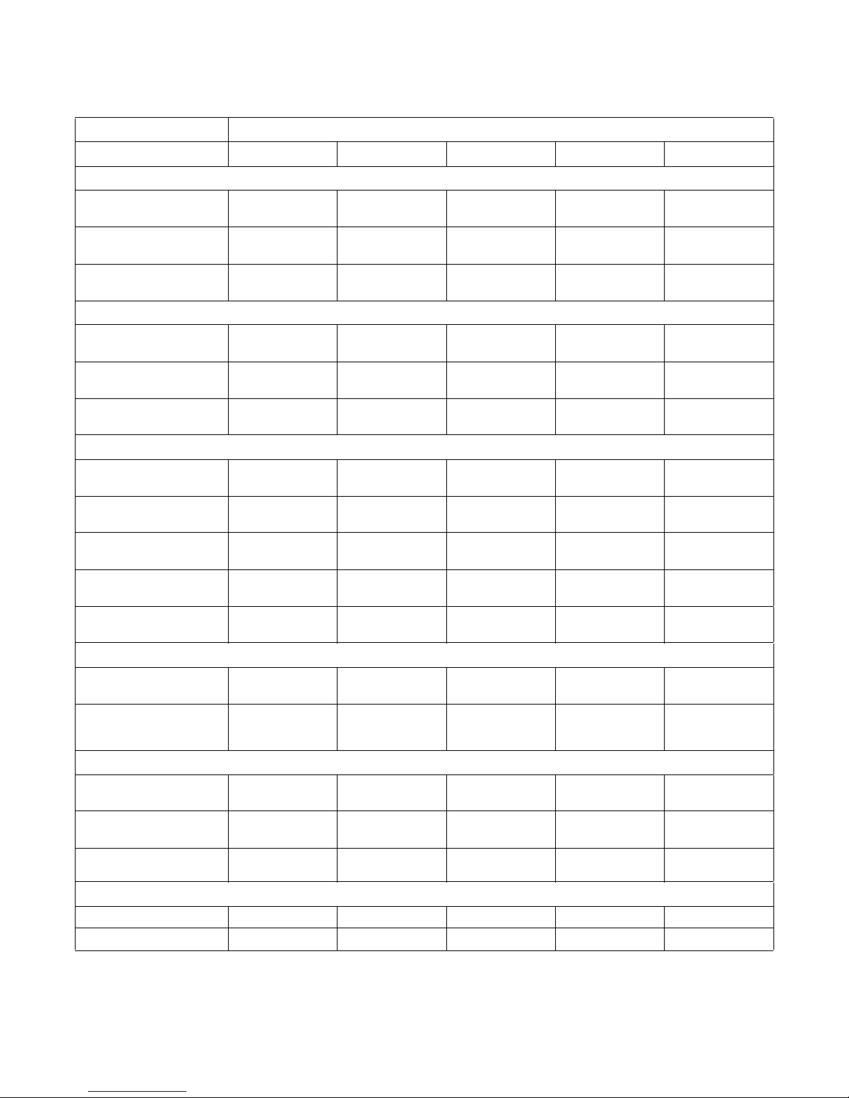
Specifications and Dimensions
Table 2 (continued)
Models
Specifications 40M 60M 80M 100M 140M
Chemical Supply System
Number of Dry Chemical
compartments, (std/opt)
Number of Liquid Supply
Connections, (std/opt)
Liquid Supply Connection
Size
1/5 1/5 1/5 1/5 1/5
6/12 6/12 6/12 6/12 6/12
1/2 NPT1/2 NPT1/2 NPT1/2 NPT1/2 NPT
Drive Train Information
Number of Motors In Drive
Train
Drive Motor Power,
hp (kW)
11111
3
(2.3)
3
(2.3)
5
(3.7)
5
(3.7)
Cylinder Speeds/Centrifugal Force Data
Possible Wash Speed,
RPM (G-Force)
Preset Wash Speed,
RPM (G-Force)
Balance Speed,
RPM (G-Force)
Preset Low Extract Speed,
RPM (G-Force)
Preset Medium Extract
Speed, RPM (G-Force)
Preset High Extract Speed,
RPM (G-Force)
Maximum SmartSpin
Speed,
RPM (G-Force)
10-60
(0.05-1.4)
46
(0.8)
81
(2.5)
361
(50)
443
(75)
511
(100)
626
(150)
10-60
(0.04-1.6)
43
(0.8)
75
(2.5)
337
(50)
413
(75)
477
(100)
584
(150)
10-60
(0.05-1.9)
39
(0.8)
69
(2.5)
309
(50)
378
(75)
437
(100)
535
(150)
10-60
(0.05-1.9)
39
(0.8)
69
(2.5)
309
(50)
378
(75)
437
(100)
535
(150)
7.5
(5.6)
10-55
(0.06-1.9)
36
(0.8)
64
(2.5)
286
(50)
351
(75)
405
(100)
496
(150)
Balance Detection
Vibration Switch Installed
STD STD STD STD STD
Electrical Heating (Optional)
Total Electrical Heating
Capacity, kW
Number of Electrical
Heating Elements
Electrical Heating Element
Size, kW
21.5@240V
21.5@480V
6 – 240V
6 – 480V
3333Not Applicable
Noise Emission
Not Applicable Not Applicable Not Applicable Not Applicable Not Applicable
C003292ENR1
© Copyright, Alliance Laundry Systems LLC - DO NOT COPY or TRANSMIT
32.2@240V
21.5@480V
9 – 240V
6 – 480V
Table 2
32.2@240V
21.5@480V
9 – 240V
6 – 480V
32.2@240V
21.5@480V
9 – 240V
6 – 480V
Not Applicable
Not Applicable
11
Page 14

Specifications and Dimensions
Machine Dimensions
Dimensional Clearances
Allow 24 inches (600 mm) at the rear of the machine
and 18 inches (450 mm) is recommended at the sides
for maintenance, inspection and adjustment.
In multiple installations, allow 18 inches (450 mm)
between machines. Machine dimensions are indicated
in Figure 2 through Figure 8. For minimum
clearances, refer to Figure 9.
12
© Copyright, Alliance Laundry Systems LLC - DO NOT COPY or TRANSMIT
C003292ENR1
Page 15
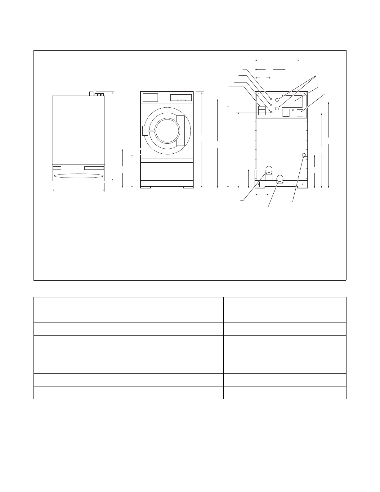
40 Pound Models
PHM727N
FRONT
REAR
TOP
D
E
F
A
B
C
G
H
I
J
K
L
M
N
O
P
4
6
7
5
1
2
3
9
8
10
Specifications and Dimensions
1 External Supply Connection 6 External Supply Wiring Connection
2 Auxiliary 7 Power Inlet
3 Hot Water 8 Steam Inlet
4 Cold Water 9 Auxiliary Drain
5 Greasing Points 10 Drain
Figure 2
A
B
C
D
E
F
G
H
45.6 in. (1158 mm)
32 in. (813 mm)
25.5 in. (648 mm)
22.5 in. (572 mm)
57 in. (1448 mm)
52 in. (1321 mm)
48 in. (1219 mm)
44 in. (1118 mm)
Table 3
I
J
K
L
M
N
O
P
11.7 in. (297 mm)
10.25 in. (260 mm)
19.35 in. (491 mm)
27.93 in. (709 mm)
21.8 in. (554 mm)
43 in. (1092 mm)
51.4 in. (1306 mm)
8.88 in. (226 mm)
PHM727N
C003292ENR1
© Copyright, Alliance Laundry Systems LLC - DO NOT COPY or TRANSMIT
13
Page 16
Specifications and Dimensions
PHM728N
REAR
FRONT
TOP
D
E
F
A
B
C
G
H
I
J
K
L
M
N
O
P
4
6
7
5
1
2
3
9
8
10
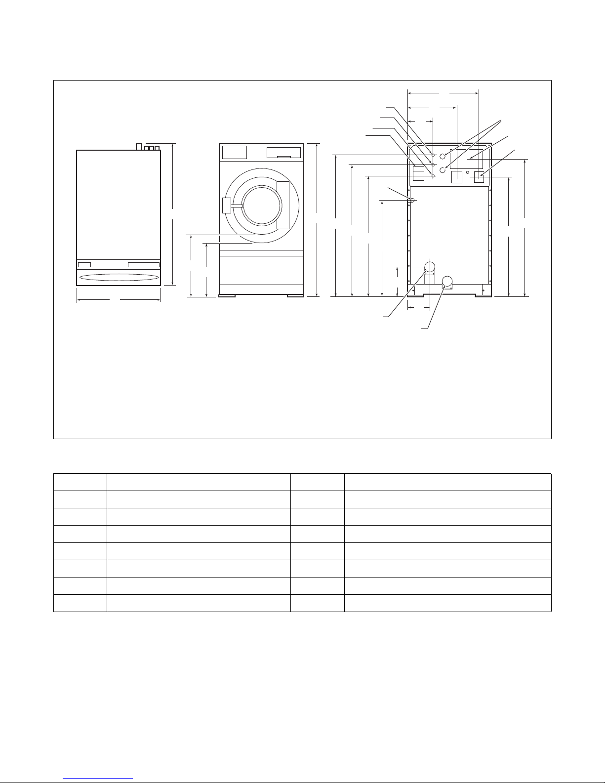
60 Pound Models
1 External Supply Connection 6 External Supply Wiring Connection
2 Auxiliary 7 Power Inlet
3 Hot Water 8 Auxiliary Drain
4 Cold Water 9 Drain
5 Greasing Points 10 Steam Inlet
Figure 3
A
B
C
D
E
F
G
H
47.8 in. (1214 mm)
34.5 in. (876 mm)
28.8 in. (732 mm)
25.8 in. (655 mm)
62.6 in. (1590 mm)
57.62 in. (1464 mm)
53.62 in. (1362 mm)
49.62 in. (1260 mm)
Table 4
K
L
M
N
O
P
I
J
38.5 in. (978 mm)
11.7 in. (297 mm)
11.5 in. (292 mm)
21.1 in. (536 mm)
29.69 in. (754 mm)
48.6 in. (1234 mm)
57.1 in. (1450 mm)
9.63 in. (245 mm)
PHM728N
14
© Copyright, Alliance Laundry Systems LLC - DO NOT COPY or TRANSMIT
C003292ENR1
Page 17

80 Pound Models
FRONT
D
E
F
A
B
C
G
H
I
J
K
L
M
N
P
4
6
5
2
3
9
8
10
1
R
O
Q
TOP
REAR
S
7
Specifications and Dimensions
PHM729N
1 External Supply Connection 6 External Supply Wiring Connection
2 Auxiliary 7 Power Inlet
3 Hot Water 8 Auxiliary Drain
4 Cold Water 9 3 in. (76.2 mm) Drain
5 Greasing Points 10 Steam Inlet
Figure 4
A
B
C
D
E
F
G
H
I
J
51.4 in. (1306 mm)
42.5 in. (1080 mm)
29.6 in. (752 mm)
26.6 in. (676 mm)
52 in. (1321 mm)
61.5 in. (1562 mm)
70 in. (1778 mm)
66 in. (1676 mm)
62 in. (1575 mm)
58 in. (1473 mm)
K
L
M
N
O
P
Q
R
S
38.4 in. (975 mm)
11.7 in. (297 mm)
12.25 in. (311 mm)
29 in. (737 mm)
37.7 in. (958 mm)
56 in. (1422 mm)
64.4 in. (1636 mm)
12 in. (305 mm)
6 in. (152 mm)
PHM729N
C003292ENR1
© Copyright, Alliance Laundry Systems LLC - DO NOT COPY or TRANSMIT
Table 5
15
Page 18

Specifications and Dimensions
FRONT
D
E
F
A
B
C
G
H
I
J
K
L
M
N
P
4
6
5
2
3
9
8
10
1
R
O
TOP
REAR
7
Q
S
100 Pound Models
I
PHM730N
1 External Supply Connection 6 External Supply Wiring Connection
2 Auxiliary 7 Power Inlet
3 Hot Water 8 Auxiliary Drain
4 Cold Water 9 3 in. (76.2 mm) Drain
5 Greasing Points 10 Steam Inlet
Figure 5
A
B
C
D
E
F
G
H
I
J
56.4 in. (1433 mm)
42.5 in. (1080 mm)
30.12 in. (765 mm)
27.13 in. (689 mm)
52 in. (1321 mm)
61.5 in. (1562 mm)
70 in. (1778 mm)
66 in. (1676 mm)
62 in. (1575 mm)
58 in. (1473 mm)
K
L
M
N
O
P
Q
R
S
38.4 in. (975 mm)
11.7 in. (297 mm)
12.25 in. (311 mm)
29 in. (737 mm)
37.7 in. (958 mm)
56 in. (1422 mm)
64.4 in. (1636 mm)
12 in. (305 mm)
6 in. (152 mm)
PHM730N
16
© Copyright, Alliance Laundry Systems LLC - DO NOT COPY or TRANSMIT
Table 6
C003292ENR1
Page 19

125 Pound Models
FRONT
D
E
F
A
B
C
G
H
I
J
K
L
M
N
P
4
6
5
2
3
9
8
1
R
O
S
TOP
REAR
7
Q
U
T
Specifications and Dimensions
1 External Supply Connection 6 Power Inlet
2 Hot Water 7 3 in. (76.2 mm) Drain
3 Cold Water 8 Auxiliary Drain
4 Auxiliary 9 Steam Inlet
5 External Supply Wiring Connection
Figure 6
A
B
C
D
E
F
G
H
I
J
56.1 in. (1425 mm)
50.3 in. (1278 mm)
34.3 in. (871 mm)
31.3 in. (795 mm)
58 in. (1473 mm)
67.6 in. (1717 mm)
77.1 in. (1958 mm)
71.7 in. (1821 mm)
67.7 in. (1720 mm)
64.5 in. (1638 mm)
M
O
Q
L
N
P
R
S
T
U
45.3 in. (1151 mm)
11.6 in. (295 mm)
6.7 in. (170 mm)
18.1 in. (460 mm)
28.8 in. (732 mm)
31.1 in. (790 mm)
63.8 in. (1621 mm)
70.2 in. (1783 mm)
19.4 in. (493 mm)
6 in. (152 mm)
PHM731N
K
C003292ENR1
63.7 in. (1618 mm)
© Copyright, Alliance Laundry Systems LLC - DO NOT COPY or TRANSMIT
Table 7
17
Page 20

Specifications and Dimensions
REAR
FRONT
TOP
D
E
F
A
B
C
G
H
I
J
K
L
M
N
P
4
6
5
2
3
9
8
1
R
O
S
7
Q
T
10
140 Pound Models
1 External Supply Connection 6 Power Inlet
2 Cold Water 7 Greasing Points
3 Hot Water 8 Auxiliary Drain
4 Auxiliary 9 3 in. (76.2 mm) Drain
5 External Supply Wiring Connection 10 Steam Inlet
Figure 7
A
B
C
D
E
F
G
H
I
J
59.1 in. (1501 mm)
50.3 in. (1278 mm)
34.3 in. (871 mm)
31.3 in. (795 mm)
58 in. (1473 mm)
67.6 in. (1717 mm)
77.1 in. (1958 mm)
70.8 in. (1798 mm)
65.7 in. (1669 mm)
45.5 in. (1156 mm)
K
L
M
N
O
P
Q
R
S
T
11.7 in. (297 mm)
12 in. (305 mm)
15.18 in. (386 mm)
17 in. (432 mm)
36.7 in. (932 mm)
45.26 in. (1150 mm)
56 in. (1422 mm)
64.4 in. (1636 mm)
19.3 in. (490 mm)
6 in. (152 mm)
PHM732N
18
© Copyright, Alliance Laundry Systems LLC - DO NOT COPY or TRANSMIT
Table 8
C003292ENR1
Page 21

175 Pound Models
REAR
FRONT
TOP
D
E
F
A
B
C
G
H
I
J
K
L
M
N
P
4
6
5
2
3
9
8
1
R
O
S
7
Q
T
10
Specifications and Dimensions
1 External Supply Connection 6 Power Inlet
2 Cold Water 7 Greasing Points
3 Hot Water 8 Auxiliary Drain
4 Auxiliary 9 3 in. (76.2 mm) Drain
5 External Supply Wiring Connection 10 Steam Inlet
Figure 8
A
B
C
D
E
F
G
H
I
J
64.1 in. (1628 mm)
50.3 in. (1278 mm)
34.3 in. (871 mm)
31.3 in. (795 mm)
58 in. (1473 mm)
67.6 in. (1717 mm)
77.1 in. (1958 mm)
73.2 in. (1859 mm)
66.2 in. (1681 mm)
45.3 in. (1151 mm)
K
L
M
N
O
P
Q
R
S
T
Table 9
11.6 in. (295 mm)
15.6 in. (396 mm)
21.6 in. (549 mm)
18.6 in. (472 mm)
28.8 in. (732 mm)
31.1 in. (790 mm)
63.8 in. (1621 mm)
70.2 in. (1783 mm)
19.4 in. (493 mm)
6 in. (152 mm)
PHM733N
C003292ENR1
© Copyright, Alliance Laundry Systems LLC - DO NOT COPY or TRANSMIT
19
Page 22

Specifications and Dimensions
Floor Load Data
Size
Machine
40M 100G
40M 150G
40H 230G
40H 300G
60M 100G
60M 150G
60H 230G
60H 300G
80M 100G
80M 150G
80H 230G
)
2
Net Wt. of
(lbs.)
Machine
Basket
Height of
Center (in.)
Max RPM
Basket
Diameter
27 1583 33.35 511 100 1701 179 786 2440 256.8 2185 8.52
27 1583 33.35 625 149.6 1701 179 706 2359 248.3 1961 10.42
27 1690 33.35 775 230 1808 190.3 1808 3569 375.7 5025 12.92
27 1690 33.35 885 300 1808 190.3 1415 3175 334.2 3931 14.75
31 1627 37.2 477 100 1807 170.9 1201 2936 277.7 3722 7.95
31 1627 37.2 585 150.5 1807 170.9 1083 2818 266.6 3359 9.75
31 1795 37.2 723 229.9 1975 186.8 2758 4661 440.9 8551 125
31 1795 37.2 826 300 1975 186.8 2160 4063 384.3 6696 13.77
37 1766 40 437 100.2 2011 139.2 1636 3549 245.7 5452 7.28
37 1766 40 535 150.2 2011 139.2 1471 3384 234.3 4903 8.92
37 1926 40 662 230 2171 150.3 3754 5826 403.5 12512 11.03
G Cal-
culated
(lbs.)
Static Load
Static Floor
(lbs./ft
Pressure
Dynamic
Load (lbs.)
Load (lbs.)
Max Vertical
)
2
(lbs./ft
Max Dynamic
Floor Pressure
(lbs./ft.)
Load Freq
Base Moment
(Hz)
80H 300G
100M 100G
100M 150G
100H 230G
100H 300G
125H 200G
125H 300G
140M 100G
140M 150G
140H 200G
140H 250G
175H 200G
175H 250G
37 1926 40 756 300 2171 150.3 2937 5010 346.9 9791 12.6
37 2007 40.3 437 100.2 2310 145.1 2025 4213 264.7 6799 7.28
37 2007 40.3 535 150.2 2310 145.1 1821 4009 251.9 6114 8.52
37 2167 40.3 662 230 2470 155.2 4646 6995 439.4 15603 11.03
37 2167 40.3 756 300 2470 155.2 3635 5984 375.9 2209 12.6
43 2749 46.5 573 200.3 3124 165.8 5006 7980 423.6 19400 9.55
43 2749 46.5 701 299.7 3124 165.8 4496 7470 396.5 17421 11.68
43 2749 46.8 405 100 3174 155.5 2835 5839 286 11057 6.75
43 2749 46.8 500 152.5 3174 155.5 2593 5597 274.2 10112 8.33
43 3027 46.8 573 200.3 3452 169.1 5675 8957 438.8 22134 9.55
43 3027 46.8 640 249.8 3452 169.1 4248 7530 368.9 16567 10.67
43 3450 46.8 573 200.3 3975 166.6 7009 10774 451.5 27335 9.56
43 3450 46.8 640 249.8 3975 166.6 5246 9011 377.6 20461 10.67
Table 10
20
© Copyright, Alliance Laundry Systems LLC - DO NOT COPY or TRANSMIT
C003292ENR1
Page 23

Specifications and Dimensions
• Always mount this machine on a solid,
stable ground floor.
• Never install a hard mount washerextractor on an above ground floor or
over a basement.
• Never use any material between the
machine and floor except grout. The use
of rubber pads, neoprene or other
materials will make the installation
unsafe, noisy and will void all
warranties.
W706
WARNING
To reduce the risk of fire, serious injury,
property damage and/or death, install the
machine on a level (within 3/8 inch),
uncovered concrete floor of sufficient
strength at grade.
W787
WARNING
Installation Instructions
Surface
These machines must be securely anchored on a solid,
flat reinforced concrete surface capable of
withstanding the weight of the machine and the
considerable forces generated during the spin/extract
cycle. Surface should be a high quality concrete
(minimum 3500 psi test strength) and at least 12 in.
(305 mm) thickness for all models. The surface should
be clean, flat and free of irregularities. The pad should
be 12 in. (305 mm) larger than the footprint of the
machine on all sides, beveling out towards the bottom
of the pad.
Anchors
The use of a minimum Grade 5 SAE rated 3/4 inch (19
mm) anchor bolt is recommended for installing
machines.
Mounting
Mounting Bolt Installation
Requirements
Location
Plan the location of the machines. When placing
machines consider the following:
• The loading door is easily accessible to your
workers and does not interfere with other
equipment.
• Make sure that the machine does not block
emergency exits, open doors, work traffic paths,
etc.
• There is adequate clearance in front of the
machine for operation.
• There is clearance behind and above the machine
to safely perform periodic maintenance. Always
check local codes. Refer to Clearances section.
On Metal Base
NOTE: Installation on a raised metal base is not
recommended.
On Concrete
Refer to Grouting and Setting Machine section.
C003292ENR1
© Copyright, Alliance Laundry Systems LLC - DO NOT COPY or TRANSMIT
21
Page 24

Specifications and Dimensions
PHM692N
24 in.
(610 mm)
24 in.
(610 mm)
18 in. (recommended)
(457 mm)
1* in. (minimum)
(25 mm)
18 in. (recommended)
(457 mm)
6* in. (minimum)
(152 mm)
Clearances
IMPORTANT: If the machines are to be mounted
less than 18 in. (457 mm) from each other or less
than 18 in. (457 mm) from a side wall, only the
inside bolt holes will be accessible. If the machines
are to be mounted less than 6 in. (152 mm) from
each other, a wall or other equipment, they must be
installed without using the skirt around the bottom,
as it cannot be reinstalled after the machines are in
place.
* When using minimum clearances for installing 80 pound or larger machines, adjustments must be made to include the width of the
single-cup (standard) or 5-cup (optional) dispenser mounted on the side of the machine. Refer to Figure 5 through Figure 8.
Figure 9
PHM692N
22
© Copyright, Alliance Laundry Systems LLC - DO NOT COPY or TRANSMIT
C003292ENR1
Page 25

Specifications and Dimensions
1
2
2 in.
(51 mm)
8 in.
(203 mm)
0.75 in.
(19 mm)
Be very careful when lifting and moving
machine. If machine falls, serious
personal injury or death may result.
W707
WARNING
Mounting Bolt Hole Locations
Use a sturdy template to guide hammer-drill into floor.
A heavy steel template/drill guide is available from
your distributor.
Make sure to follow bolt manufacturer’s
recommendation for bit size for the particular anchors
you are using.
The dimensions shown in Figures 11 through 13 are
patterns for various models.
Installing Anchors
1. Measure holes to verify that they match bolt hole
pattern in base of frame.
2. Drill holes for anchor bolts. Refer to Figure 10.
Grouting and Setting Machine
After concrete has cured and anchor bolts are properly
set, proceed as follows:
1. Remove two 1/4-20 bolts that secure trim skirt
and remove skirt.
2. Carefully position machine over anchor bolts and
lower it into place – all anchor bolts should pass
through the frame holes easily.
3. Using 4 removable spacers, raise machine about
1/2 in. (13 mm) and level it both front to rear and
side-to-side. The machine should rest on 4 points
when this operation is completed.
4. Remove rear panel so inside is accessible for
grouting.
PHM178N
1 Frame
2 Grout
Figure 10
3. Clean out anchor holes and floor around them.
4. Insert anchors and secure them per their
manufacturer’s installation instructions.
5. Mix enough machinery grout to fill all spaces
between machine base and floor. Grout
completely under all frame members. Force grout
under machine base until all voids are filled.
6. Before grout has set and become stiff, carefully
remove spacers, allowing machine to settle into
wet grout.
7. When grout is fully cured, place lock-washers
and nuts on anchor studs. Tighten nuts in even
increments using a diagonal pattern. This will
help insure equal tension at all anchor points.
NOTE: After machine has been in place and
operated for a day, retighten anchor bolts.
C003292ENR1
© Copyright, Alliance Laundry Systems LLC - DO NOT COPY or TRANSMIT
23
Page 26

Specifications and Dimensions
F
A
L
C
G
J
M
H
K
D
E
B
I
FRONT OF MACHINE
REAR OF MACHINE
WALL
N
P
O
24 in. (610 mm) min. recommended for service
PHM763N
Mounting Bolt Hole Locations
IMPORTANT: All drawings are not to scale.
40 Pound Models
24
© Copyright, Alliance Laundry Systems LLC - DO NOT COPY or TRANSMIT
Figure 11
C003292ENR1
Page 27

Model 40 Pound
A
B
C
D
E
F
G
H
I
J
K
L
M
N
O
P
4 in. (102 mm)
1 in. (25 mm)
5.5 in. (140 mm)
30.5 in. (775 mm)
17.5 in. (445 mm)
9 in. (229 mm)
5.5 in. (140 mm)
31.32 in. (796 mm)
22.85 in. (580 mm)
34.73 in. (882 mm)
27.34 in. (694 mm)
37.03 in. (941 mm)
42.78 in. (1087 mm)
21 in. (533 mm)
30 in. (762 mm)
32 in. (813 mm)
Specifications and Dimensions
Tab le 11
C003292ENR1
© Copyright, Alliance Laundry Systems LLC - DO NOT COPY or TRANSMIT
25
Page 28

Specifications and Dimensions
PHM764N
F
A
L
C
G
J
M
H
K
D
E
B
I
FRONT OF MACHINE
REAR OF MACHINE
WALL
Q
S
R
24 in. (610 mm) min. recommended for service
O
P
N
60, 80 and 100 Pound Models
26
© Copyright, Alliance Laundry Systems LLC - DO NOT COPY or TRANSMIT
Figure 12
PHM764N
C003292ENR1
Page 29

Specifications and Dimensions
Model 60 Pound 80 Pound 100 Pound
A
B
C
D
E
F
G
H
I
J
4 in.
(102 mm)
1.5 in.
(38 mm)
5.5 in.
(140 mm)
35 in.
(889 mm)
26.25 in.
(667 mm)
17.5 in.
(445 mm)
8.75 in.
(222 mm)
4 in.
(102 mm)
32.69 in.
(830 mm)
25.07 in.
(637 mm)
1.5 in.
(38 mm)
1.5 in.
(38 mm)
7 in.
(178 mm)
41.5 in.
(1054 mm)
33 in.
(838 mm)
22 in.
(559 mm)
11 in.
(279 mm)
4 in.
(102 mm)
41 in.
(1041 mm)
30.55 in.
(776 mm)
6.5 in.
(165 mm)
1.5 in.
(38 mm)
7 in.
(178 mm)
41.5 in.
(1054 mm)
33 in.
(838 mm)
22 in.
(559 mm)
11 in.
(279 mm)
4 in.
(102 mm)
41 in.
(1041 mm)
30.55 in.
(776 mm)
M
N
O
Q
R
K
L
36.03 in.
(915 mm)
29.3 in.
(744 mm)
35.23 in.
(895 mm)
41 in.
(1041 mm)
47.09 in.
(1196 mm)
P
41.16 in.
(1045 mm)
23.5 in.
(597 mm)
31.5 in.
(800 mm)
S
34.5 in.
(876 mm)
45.21 in.
(1148 mm)
36 in.
(914 mm)
43.6 in.
(1107 mm)
51.47 in.
(1307 mm)
57.29 in.
(1455 mm)
50.34 in.
(1279 mm)
28.5 in.
(724 mm)
39.5 in.
(1003 mm)
42.5 in.
(1080 mm)
45.21 in.
(1148 mm)
36 in.
(914 mm)
43.6 in.
(1107 mm)
51.47 in.
(1307 mm)
57.29 in.
(1455 mm)
50.34 in.
(1279 mm)
28.5 in.
(724 mm)
39.5 in.
(1003 mm)
42.5 in.
(1080 mm)
Table 12
C003292ENR1
© Copyright, Alliance Laundry Systems LLC - DO NOT COPY or TRANSMIT
27
Page 30

Specifications and Dimensions
F
A
L
C
G
J
M
H
K
D
E
B
I
FRONT OF MACHINE
REAR OF MACHINE
Q
S
R
24 in. (610 mm) min. recommended for service
O
P
N
WALL
125, 140 and 175 Pound Models
28
© Copyright, Alliance Laundry Systems LLC - DO NOT COPY or TRANSMIT
Figure 13
PHM762N
C003292ENR1
Page 31

Specifications and Dimensions
Model 125 Pound 140 Pound 175 Pound
H-Series H-Series H-Series
A
B
C
D
E
F
G
H
I
J
3.93 in.
(100 mm)
1.5 in.
(38 mm)
7 in.
(178 mm)
47.5 in.
(1207 mm)
27 in.
(686 mm)
18 in.
(457 mm)
9 in.
(229 mm)
3.5 in.
(89 mm)
48.1 in.
(1222 mm)
37.35 in.
(949 mm)
3.5 in.
(89 mm)
1.5 in.
(38 mm)
7 in.
(178 mm)
49 in.
(1245 mm)
27 in.
(686 mm)
18 in.
(457 mm)
9 in.
(229 mm)
3.5 in.
(89 mm)
48.1 in.
(1222 mm)
37.35 in.
(949 mm)
2.5 in.
(64 mm)
1.5 in.
(38 mm)
7 in.
(178 mm)
54 in.
(1372 mm)
27 in.
(686 mm)
18 in.
(457 mm)
9 in.
(229 mm)
1.5 in.
(38 mm)
48.1 in.
(1222 mm)
37.35 in.
(949 mm)
M
K
L
50.56 in.
(1284 mm)
40.47 in.
(1028 mm)
45.2 in.
(1148 mm)
N
O
P
Q
R
S
54.42 in.
(1382 mm)
67 in.
(1702 mm)
59.75 in.
(1518 mm)
36.25 in.
(921 mm)
47.25 in.
(1200 mm)
50.25 in.
(1276 mm)
50.56 in.
(1284 mm)
40.47 in.
(1028 mm)
45.2 in.
(1148 mm)
54.42 in.
(1382 mm)
68.07 in.
(1729 mm)
60.95 in.
(1548 mm)
36.25 in.
(921 mm)
47.25 in.
(1200 mm)
50.25 in.
(1276 mm)
50.56 in.
(1284 mm)
40.47 in.
(1028 mm)
45.2 in.
(1148 mm)
54.42 in.
(1382 mm)
71.75 in.
(1822 mm)
68.27 in.
(1734 mm)
36.25 in.
(921 mm)
47.25 in.
(1200 mm)
50.25 in.
(1276 mm)
Table 13
C003292ENR1
© Copyright, Alliance Laundry Systems LLC - DO NOT COPY or TRANSMIT
29
Page 32

Specifications and Dimensions
To prevent personal injury, avoid contact
with inlet water temperatures higher than
125° Fahrenheit (51° Celsius) and hot
surfaces.
W748
WARNING
P038I
1
2
Water Connection
Water service should have the following:
• Hot water temperature should be a maximum of
190°F (88°C).
• Water pressure should be between 30 and 85 psi
(2 to 7 bar).
• Install screen filters in water supply lines to keep
rust, grit or other foreign material out of solenoid
valves.
• Suitable air cushions (risers) should be installed
in supply lines to prevent “hammering.” Refer to
Figure 14.
To connect water feeders to rear of machine, use
flexible hoses. Because this is a vibrating machine,
water lines must allow for movement or leaks may
result. Hang hoses in a large loop behind machine so
that they are not kinked or pinched.
P038I
1 Air Cushions (Risers)
2 Water Supply Faucets
Figure 14
For machines labeled with the CE mark, backsiphon
protection devices must be installed previous of all
machine water inlet valves in accordance with
accepted European standards.
30
© Copyright, Alliance Laundry Systems LLC - DO NOT COPY or TRANSMIT
C003292ENR1
Page 33

Specifications and Dimensions
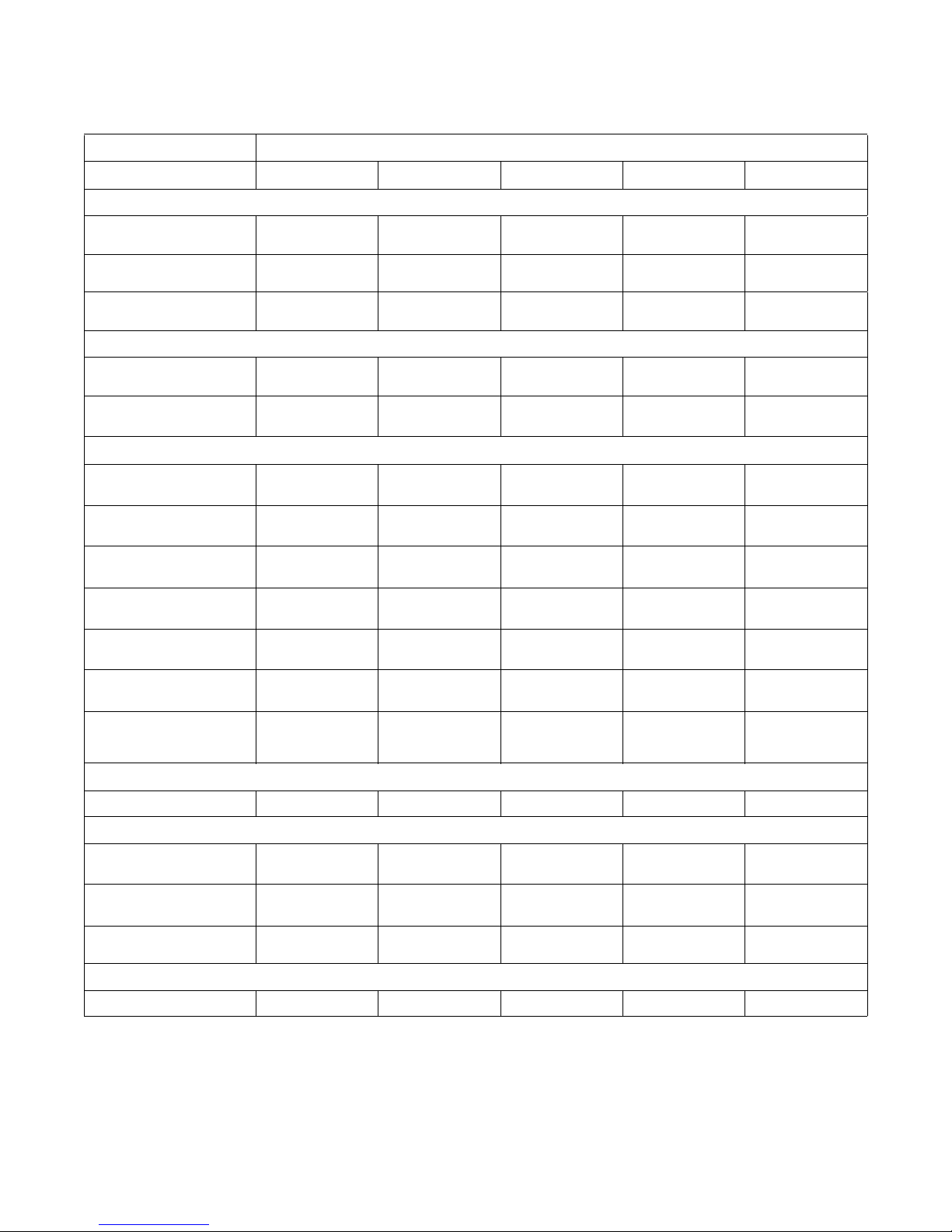
Drain Connection Requirements
A flexible connection must be made to a vented drain
system to prevent an air lock and to prevent siphoning.
IMPORTANT: Machines must be installed in
accordance with all local codes and ordinances.
IMPORTANT: The top of the vent must be 12
inches (304.8 mm) lower than bottom of inlet
valves.
Drain Information
Specifications
Overflow Size,
in. (mm)
Drain connection size, I.D.,
in. (mm) with second drain
Number of drain outlets*
Drain flow capacity,
gal/min. (l/min.)
Recommended drain pit
size, ft3 (l) †
†Sized for one machine using high level.
*Data reflects single drain, dual drain is optional.
IPH40
IPM40
1.5
(38.1)
2
(50.8)
1111111
30
(114)
5
(142)
IPH60
IPM60
1.5
(38.1)
3
(76.2)
70
(265)
12
(340)
If proper drain size is not available or practical, a surge
tank is required. A surge tank along with a sump pump
should be used when gravity drainage is not possible.
Increasing drain hose length, installing elbows or
causing bends will decrease drain flow rate and
increase drain times, impairing machine performance.
IPH80
IPM80
1.5
(38.1)
3
(76.2)
60
(227)
9
(255)
IPH100
IPM100
1.5
(38.1)
3
(76.2)
65
(246)
11
(311)
IPH125
3
(76.2)
3
(76.2)
125
(473)
36
(1019)
IPH140
IPM140
3
(76.2)
3
(76.2)
125
(473)
36
(1019)
IPH175
3
(76.2)
3
(76.2)
125
(473)
36
(1019)
Table 14
C003292ENR1
© Copyright, Alliance Laundry Systems LLC - DO NOT COPY or TRANSMIT
31
Page 34

Specifications and Dimensions
4
1
2
5
6
7
3
1 Rear of Machine
2 Drain Pipe
3 1 in. (25.4 mm) Minimum Air Gap
4 Steel Grate
5 Drain Trough
6 Strainer
7 Waste Line
PHM621N
Figure 15
NOTE: Installation of additional machine will
require proportionately larger drain connections.
32
© Copyright, Alliance Laundry Systems LLC - DO NOT COPY or TRANSMIT
C003292ENR1
Page 35

Specifications and Dimensions
This machine must be installed, adjusted,
and serviced by qualified electrical
maintenance personnel familiar with the
construction and operation of this type of
machinery. They must also be familiar
with the potential hazards involved.
Failure to observe this warning may result
in personal injury and/or equipment
damage, and may void the warranty.
SW004
WARNING
Dangerous voltages are present in the
electrical control box(es) and at the motor
terminals. Only qualified personnel
familiar with electrical test procedures,
test equipment, and safety precautions
should attempt adjustments and
troubleshooting. Disconnect power from
the machine before removing the control
box cover, and before attempting any
service procedures.
SW005
WARNING
Ensure that a ground wire from a proven
earth ground is connected to the ground
lug near the input power block on this
machine. Without proper grounding,
personal injury from electric shock could
occur and machine malfunctions may be
evident.
SW008
WARNING
Never touch terminals or components of
the AC inverter drive unless power is
disconnected and the “CHARGE”
indicator LED is off. The AC inverter drive
retains potentially deadly voltage for some
time after the power is disconnected.
There are no user-serviceable parts inside
the AC inverter drive. Tampering with the
drive will void the warranty.
SW009
WARNING
When controlling the AC inverter drive
with a parameter unit, the machine’s
computer and its safety features are
bypassed. This would allow the basket to
rotate at high speeds with the door open.
When using a parameter unit to control the
AC inverter drive, a large sign should be
placed on the front of the machine
warning people of the imminent danger.
SW003
DANGER
This machine must be protected by a
circuit breaker. DO NOT USE FUSES!
W691
WARNING
Electrical Installation Requirements
IMPORTANT: Electrical ratings are subject to
change. Refer to serial decal for electrical ratings
information specific to your machine.
The AC inverter drive requires a clean power supply
free from voltage spikes and surges. Use a voltage
monitor to check incoming power.
If input voltage measures above 230V for a 200V
drive or above 460V for a 400V drive, ask the power
company to lower the voltage. As an alternative, a
step-down transformer kit is available from the
distributor. Voltages above 240 and 480 require
additional measures. Contact a qualifiied electrical
maintenance person for assistance.
Electrical connections are made at the rear of the
machine. The machine must be connected to the
proper electrical supply shown on the identification
plate attached to the side of the control module.
IMPORTANT: Alliance Laundry Systems
warranty does not cover components that fail as a
result of improper input voltage.
C003292ENR1
© Copyright, Alliance Laundry Systems LLC - DO NOT COPY or TRANSMIT
33
Page 36

Specifications and Dimensions
Do not use a phase adder on any variablespeed machine.
SW037
CAUTION
Failure to provide this equipment with a
proper proven earth ground may result in
a severe shock hazard and may increase
EMI emissions.
W708
WARNING
The AC drive provides thermal overload protection for
the drive motor. However, a separate circuit breaker or
electrical supply disconnecting device must be
installed for complete electrical overload protection.
This prevents damage to the AC drive by
disconnecting all legs if one should be lost
accidentally.
IMPORTANT: Do NOT use fuses in place of a
circuit breaker.
The machine should be connected to an individual
branch circuit not shared with lighting or other
equipment.
The connection should be shielded in a liquid-tight or
approved flexible conduit with proper conductors of
correct size installed in accordance with the National
electric Code or with applicable codes. The connection
must be made by a qualified electrician using the
wiring diagram provided with the machine or
according to accepted European standards for
machines labeled with the CE mark.
Use wire sizes indicated in Table 15 for runs up to
50 feet (15.24 meters). Use next larger size for runs of
50 to 100 feet (15.24 to 30.48 meters). Use 2 sizes
larger for runs greater than 100 feet (30.48 meters).
For personal safety and for proper operation, the
machine must be grounded in accordance with local
codes. If such codes are not available, grounding must
conform with the National Electric Code, article
205-95 or accepted European standards for machines
labeled with the CE mark. The ground connection
must be made to a proven earth ground, not to conduit
or water pipes.
Circuit Breakers
The machines are to be connected to individual
common trip circuit breakers. Use only UL 489 rated
circuit breakers. Fuses are not to be used in any
installations. (Fuses may fail separately causing a
single-phase voltage condition.) A single-phase
condition will cause the other lines to have a
considerable change in current draw suddenly, which
may cause the inverter to fail. Do not install more than
one machine per breaker and do not install any other
equipment on the breaker supplying the machine. If
there is a “stinger” leg (also known as high leg, red
leg, etc.) it must be connected to L3 of the terminal
block of the machine. A line reactor is highly
recommended.
Grounding
All equipment should be grounded with a proven earth
ground. Do not use water pipes or electrical conduit as
an earth ground path. All grounding and wiring must
conform to local and national electrical codes.
Wire Size
Wire size must meet or exceed all codes for breaker
size.
Use either SO type cord or flex conduit with stranded
copper conductors of prescribed size for power supply
between machine and wall. Because this machine
vibrates in normal operation, hard conduit may
become loose and cause wire abrasion and solid
conductor wires may break during normal operation
on vibrating machines.
34
© Copyright, Alliance Laundry Systems LLC - DO NOT COPY or TRANSMIT
C003292ENR1
Page 37

Specifications and Dimensions
Pocket Hardmount
Electrical Specifications
Voltage Designation Standard Electric Heat
Model
40H
60H
80H
100H
125H
140H
175H
2
Code
Voltag e
Cycle
Phase
Wire
Full Load
Amps
Breaker
AWG
mm
Full Load
Amps
Breaker
AWG
N 380 – 480 50/60 3 3 4 15 14 2.5 29 35 8 10
Q 200 – 240 50/60 3 3 8 15 14 2.5 56 60 6 16
X 200 – 240 50/60 1/3 2/3 11 15 14 2.5 56 60 6 16
N 380 – 480 50/60 3 3 6 15 14 2.5 29 35 8 10
Q 200 – 240 50/60 3 3 11 15 14 2.5 84 90 3 25
X 200 – 240 50/60 1/3 2/3 12 15 14 2.5 84 90 3 25
N 380 – 480 50/60 3 3 8 15 14 2.5 31 35 8 10
Q 200 – 240 50/60 3 3 15 20 12 4 87 110 2 35
N 380 – 480 50/60 3 3 8 15 14 2.5 32 40 8 10
Q 200 – 240 50/60 3 3 15 20 12 4 88 110 2 35
N 380 – 480 50/60 3 3 10 15 14 2.5
Not Available
Q 200 – 240 50/60 3 3 19 30 10 6
N 380 – 480 50/60 3 3 11 15 14 2.5
Not Available
Q 200 – 240 50/60 3 3 20 30 10 6
N 380 – 480 50/60 3 3 15 20 12 4 Not Available
2
mm
N 380 – 480 50/60 3 3 3 15 14 2.5 29 35 8 10
40M
Q 200 – 240 50/60 3 3 5 15 14 2.5 56 60 6 16
X 200 – 240 50/60 1/3 2/3 9 15 14 2.5 56 60 6 16
N 380 – 480 50/60 3 3 5 15 14 2.5 29 35 8 10
60M
Q 200 – 240 50/60 3 3 9 15 14 2.5 84 90 3 25
X 200 – 240 50/60 1/3 2/3 11 15 14 2.5 84 90 3 25
N 380 – 480 50/60 3 3 6 15 14 2.5 31 35 8 10
80M
Q 200 – 240 50/60 3 3 11 15 14 2.5 87 110 2 35
N 380 – 480 50/60 3 3 7 15 14 2.5 32 40 8 10
100M
Q 200 – 240 50/60 3 3 12 15 14 2.5 88 110 2 35
N 380 – 480 50/60 3 3 8 15 14 2.5
140M
Q 200 – 240 50/60 3 3 16 20 12 4
Not Available
NOTE: Wire-size based on: NFPA 70 (NEC), Table 310.16, 75°C Column. No more than three current carrying
conductors per raceway. Use copper conductors only. Use circuit breakers only. Do not use fuses. Suggested breaker
size based on NFPA 70, Section 240.6. Contact local authority having jurisdiction for additional information. Local
electrical codes supersede all suggestions of this table. Follow all local electrical codes. Local is defined as place of
machine installation.
Table 15
C003292ENR1
© Copyright, Alliance Laundry Systems LLC - DO NOT COPY or TRANSMIT
35
Page 38

Specifications and Dimensions
50Hz
60Hz
N
1
Making Connections to Machine
After electrical service feeder has been installed and
electrical service voltage verified by a volt meter,
follow this procedure to connect service to the
equipment.
1. Remove screw securing electrical service
connection panel and remove panel from
machine.
2. Install an appropriate strain relief or conduit
connector in cover.
3. Feed wire through connector leaving about 6 in.
(150 mm) pigtails on inside of cover. Strip about
3/8 in. (10 mm) insulation off the end of each
wire.
4. Tighten strain relief or conduit connector in
place.
5. Connect ground wire to ground terminal at
electrical service connections on machine.
6. Connect L1, L2 and L3 to terminal block
provided at electrical service connections on
machine.
7. Reinstall panel onto rear of machine and tighten
cover screw.
Adjusting Control Transformer Taps
Adjust control transformer to deliver correct voltage to
machine controls.
7. Power up machine temporarily and, using a volt
meter, verify the voltage on transformer
secondary is between 100 and 130 VAC.
Provisions for 50 Hz Installations
If machine is to be installed on a 50 Hz power system,
adjust control transformer taps as described in
Adjusting Control Transfer Taps section. Then
change drain valve wiring as follows:
1. Disconnect power from machine. Follow lockout/tag-out procedures.
2. Remove lower rear panel to access drain valves.
3. Snap black plastic cover off of each drain valve
motor by locating and squeezing two tabs on
each cover.
4. On each drain valve motor there are three
terminals (labeled 60 Hz, 50 Hz and N). Locate
these terminals.
5. On each drain valve motor, move wire from 60
Hz tap to 50 Hz tap. There should be wires on 50
Hz terminal and N terminal.
6. Reinstall black plastic motor covers.
7. Reinstall rear panel.
8. Reconnect power to machine.
NOTE: If the proper tap on drain valve motor is
not selected it will run hot and will be damaged.
1. Measure line-to-line voltage to be supplied to
machine with a volt meter.
2. Refer to the schematic supplied with machine
and locate transformer terminal chart.
3. In this chart, locate the primary voltage range,
which corresponds to line voltage measured
above, and note terminals which would be used
on primary.
4. In the chart, locate the secondary terminals
corresponding to line voltage. If line voltage is
not in chart, round it up to the next higher
voltage, which is in the chart, or contact a service
technician for assistance.
5. Remove two screws holding rear electrical
enclosure in place and remove rear electrical
enclosure cover.
6. Locate control transformer in enclosure – the
primary is on the right of the transformer and the
secondary terminals are on the left. Make sure
terminals are connected to primary and
secondary terminals selected in steps 3 and 4.
36
© Copyright, Alliance Laundry Systems LLC - DO NOT COPY or TRANSMIT
PHM695N
1 Cover
Figure 16
C003292ENR1
Page 39

Specifications and Dimensions
Hot Surfaces. Will cause severe burns.
Turn steam off and allow steam pipes,
connections and components to cool
before touching.
W505
WARNING
Steam Requirements
(Steam Heat Option Only)
Steam inlet connection, in. (mm)
Number of steam inlets
Recommended pressure,
psi (bar)
Maximum pressure,
psi (bar)
1/2 (DN13) 1/2 (DN13) 1/2 (DN13) 1/2 (DN13) 3/4 (DN19) 3/4 (DN19)
For machines equipped with optional steam heat,
install piping in accordance with approved commercial
steam practices. Steam requirements are shown in
Table 16.
NOTE: Failure to install supplied steam filter may
void warranty.
Steam Supply Information
40 60 80 100 125 140/175
111111
30 – 80
(2 – 5.5)
80
(5.5)
30 – 80
(2 – 5.5)
80
(5.5)
Table 16
30 – 80
(2 – 5.5)
80
(5.5)
30 – 80
(2 – 5.5)
80
(5.5)
30 – 80
(2 – 5.5)
80
(5.5)
30 – 80
(2 – 5.5)
80
(5.5)
C003292ENR1
© Copyright, Alliance Laundry Systems LLC - DO NOT COPY or TRANSMIT
37
Page 40

Specifications and Dimensions
Dangerous Chemicals. May damage eyes
and skin. Wear eye and hand protection
when handling chemicals; always avoid
direct contact with raw chemicals. Read
the manufacturer’s directions for
accidental contact before handling
chemicals. Ensure an eye-rinse facility
and an emergency shower are within easy
reach. Check at regular intervals for
chemical leaks.
W363
WARNING
Dispenser
Pump
1
3
2
4
1
2
3
4
Chemical Injection Supply System
IMPORTANT: Undiluted chemical dripping can
damage the machine. All chemical injection supply
dispenser pumps and dispenser tubing should be
mounted below the washer’s injection point. Loops
do not prevent drips if these instructions are not
followed. Figure 17 shows a typical chemical
injection supply system.
IMPORTANT: Failure to follow these instructions
could damage the machine and void the warranty.
Chemical Service Connections
Chemical service connections are located inside the
machine’s rear electrical enclosure. Provisions
include:
• Clearly marked chemical signal locations.
• Chemical signals are prewired for 85 VAC
signals (85 VAC on, 0 VAC off) and can be easily
changed to accommodate dry contact chemical
signal formats.
• Up to 12 chemical signals are available.
• A timer hold input is available for use with
dispensing systems feeding multiple machines.
• 7/8 in. (22 mm) hole is provided in rear electrical
panel cover for mounting a typical chemical
pump interface module or feeding chemical
pump control signal wires.
Connection of Chemical Supply Hoses
To connect a chemical supply hose to machine:
1. Remove one of the plastic plugs from an
injection port.
2. Screw one of the six 3/8 in. (10 mm) nipples
supplied with machine into open injection port.
1 Chemical Signal Connections
2 Supply Hose
3 Chemical Injection Connections
4 Dispenser Pump
38
Figure 17
© Copyright, Alliance Laundry Systems LLC - DO NOT COPY or TRANSMIT
PHM911N
3. Connect feed hose to nipple and secure hose with
a hose clamp.
4. Ideally, pump system should be mounted so that
it is lower than chemical injection ports. Hose
connections at injection port should be highest
point in hose to prevent chemical drippage. Refer
to Figure 17.
PHM690N
1 Chemical Injection Port
2 Chemical Hose
3 Pump
4 Chemical Bucket
Figure 18
C003292ENR1
Page 41

PHM691N
HOLD
HOLD RELAY COM
HOLD RELAY NO
SIGNAL 6 COM
SIGNAL 6
SIGNAL 5 COM
SIGNAL 5
SIGNAL 4 COM
SIGNAL 4
SIGNAL 3 COM
SIGNAL 3
SIGNAL 2 COM
SIGNAL 2
SIGNAL 1 COM
SIGNAL 1
PUMP SYSTEM
INTERFACE MODULE
HOLD
COM
COM
6
5
4
3
2
1
This machine is not designed to provide
power for a chemical pump system!
Connecting such a load to the machine’s
controls may overload the control
transformer! Never connect power for any
device to the machine’s main power
terminal block – this is a violation of the
NEC and other electrical regulations.
W692
WARNING
Figure 19
Connection of Chemical Pump Signals
To connect pump control to AC voltage signals, do the
following:
Specifications and Dimensions
NOTE: Consult factory service or distributor for
assistance with dry contact format signals (to drive
pumps directly, for example).
1. Remove large rear electrical module cover on
machine to access chemical terminals.
2. Mount pump system interface module using 7/8
in. (22 mm) hole in cover so that box will be on
outside of machine when panel is reinstalled.
3. Connect pump system signal wires 1 through 6 to
terminals 1 through 6 on the machine chemical
signal terminal block.
4. Connect all pump system signal common wires
to two machine chemical signal terminals labeled
“COM” (it is recommended to connect three
wires to each COM terminal as drawn in
Figure 19 – each terminal can accommodate up
to three 16 AWG wires).
5. If a chemical timer hold function is being used
(this is common on solid supply systems
connected to multiple machines), connect hold
relay common terminal to one of two “HOLD”
terminals. Connect chemical hold relay normally
open wire to remaining “HOLD” terminal as
shown in diagram.
6. Reinstall rear electrical module cover with
chemical system interface module mounted on it.
7. Finish pump system installation per its
C003292ENR1
manufacturer’s instructions.
© Copyright, Alliance Laundry Systems LLC - DO NOT COPY or TRANSMIT
39
Page 42

First Start-Up
IMPORTANT: The following safety checks are to
be performed BEFORE initial start-up.
1. Make sure all electrical and plumbing
connections have been made in accordance with
applicable codes and regulations.
2. Make sure machine is electrically grounded. This
is a high leakage current device! Improper
grounding can cause electrical shock hazards and
EMI problems.
3. Make sure all service connections (water, drain,
electrical, steam, etc.) to equipment are flexible
and are of correct size, length and type. Make
sure there are no kinks and that all clamps and
attachment points are secure.
4. Make sure all transport brackets have been
removed (where applicable).
5. Make sure machine is properly grouted to floor
and leveled. Always allow plenty of time for
grout to cure before tightening anchor bolts and
running machine.
6. Make sure anchor bolts have been tightened
properly.
IMPORTANT: The following safety checks are to
be performed DURING the initial start-up.
Contact a qualified technician if necessary.
1. Verify door lock system works properly. Do this
by checking if machine starts a cycle with
loading door open or loading door can be opened
while machine is in operation.
2. Verify machine does not move or vibrate
excessively. Do this by loading machine with a
small load of laundry (about half capacity) and
running a program with a high-speed extract. The
machine should be reasonably quiet and still
during the extract.
40
© Copyright, Alliance Laundry Systems LLC - DO NOT COPY or TRANSMIT
C003292ENR1
Page 43

Operation
Be careful around the open door,
particularly when loading from a level
below the door. Impact with door edges
can cause personal injury.
SW025
WARNING
PHM833N
PHM834N
1 2 3
4 5 6
7 8 9
0
PS40
PROG
RUN
PHM1398C
PHM840N
1 2 3
4 5 6
7 8 9
0
PS40
PROG
RUN
1
General Operation Instructions
1. Open door.
2. Load to capacity. DO NOT OVERLOAD.
4. Enter number of desired program.
Figure 22
5. Fill dispenser cups with appropriate chemicals, if
necessary.
Figure 20
3. Close and lock door.
Figure 21
C003292ENR1
© Copyright, Alliance Laundry Systems LLC - DO NOT COPY or TRANSMIT
Figure 23
6. Press START button.
PHM1398C
1 START keypad
Figure 24
41
Page 44

Operation
The PS40’s fault codes indicate
potentially hazardous operating
conditions. If a Fault occurs the machine
should be shut off and locked out until a
service technician can repair the machine.
All fault codes are indicated by a flashing
“Fn” display. Where ‘F’ indicates a fault
condition, and ‘n’ indicates the particular
fault number.
W687
WARNING
7. Machine door will automatically lock and cycle
will begin.
8. When program is completed, display will display
“open door” and door will automatically unlock
and is ready to be opened.
42
© Copyright, Alliance Laundry Systems LLC - DO NOT COPY or TRANSMIT
C003292ENR1
Page 45

Maintenance
Sharp edges can cause personal injury.
Wear safety glasses and gloves, use
proper tools and provide lighting when
handling sheet metal parts.
W366R1
WARNING
Replace all panels that are removed to
perform service and maintenance
procedures. Do not operate the machine
with missing guards or with broken or
missing parts. Do not bypass any safety
devices.
SW019
CAUTION
Do not spray the machine with water. Short
circuiting and serious damage may result.
W782
WARNING
To reduce the risk of electrical shock, serious
injury or death, disconnect the electrical power to
washer-extractor before examining the wiring.
W636
WARNING
Do not clean the cooling fans with
compressed air! Doing this spins the fan
too fast and will cause premature fan
failures.
W695
WARNING
Maintenance procedures described below will prolong
life of machine and help prevent accidents.
Daily
Beginning of Day
3. Inspect steam hose connections for leaks (where
applicable).
4. Inspect all chemical inlets, lines and connections
for leaks.
5. Verify insulation is intact on all external wires
and all connections are secure. If bare wire is
evident, call a service technician.
End of Day
1. Clean AC drive filter:
a. Remove external plastic cover which contains
filter.
b. Remove foam filter from cover.
c. Wash filter with warm water and allow to air
dry. Filter can be vacuumed clean.
1. Check door interlock before starting operation:
a. Attempt to start with door open. Machine
should not start.
b. Close door without locking it and attempt to
start. Machine should not start.
c. Close and lock door and start a cycle. Attempt
to open door. Door should not open.
If door lock and interlock are not functioning
properly disconnect power and call a service
technician.
IMPORTANT: Door lock should be checked daily
to ensure proper operation. Also, check that all
safety and instruction labels are on the machine.
Replace as necessary.
2. Inspect water inlet valve hose connections on
C003292ENR1
back of machine for leaks.
© Copyright, Alliance Laundry Systems LLC - DO NOT COPY or TRANSMIT
IMPORTANT: The control module cover and fan
filter must be in place for the fan to properly cool
the AC inverter drive. Failure to observe this
warning will void the warranty and could lead to
expensive AC inverter drive repair.
2. Clean door gasket of residual detergent and all
foreign matter.
3. Clean supply cup dispenser and lid inside and out
with mild detergent. Rinse with clean water.
4. Clean machine’s top, front and side panels with
mild detergent. Rinse with clean water.
NOTE: Unload machine promptly after each
completed cycle to prevent moisture buildup. Leave
loading door open at end of each completed cycle to
allow moisture to evaporate.
43
Page 46

Maintenance
Never mix grease types (Ex. Silicon,
Petroleum, Lithium, Poly-Urea)! Never use
any grease other than that specified at the
grease fittings on the machine. Doing so
may cause premature bearing failure and
void any applicable warranties.
W694
WARNING
Weekly
1. Check machine for leaks.
a. Start an unloaded cycle to fill machine.
b. Verify that door and door gasket do not leak.
c. Verify that drain valve is operating and that
drain system is free from obstruction. If water
does not leak out during prewash segment,
drain valve is closed and functioning properly.
Monthly
NOTE: Disconnect power to machine at its source
before performing monthly maintenance
procedures.
Keep the following lubricants on hand for periodic
maintenance of machine.
Main
Bearings
Motor
Shell Alvania
Motor bearings are sealed and do not
require service.
®
71125 Grease
The grease must have the following
characteristics:
• NLGI Grade 2
(Recommended: Shell Alvania
®
#71125)
• Lithium-based
• Water-insoluble
• Anti-rusting
• Anti-oxidizing
• Mechanically stable
The grease must have adequate base oil viscosity
with one of the following ratings:
• ISO VG 150 (709 – 871 SUS at 100°F or
135 – 165 cSt at 40°C)
• ISO VG 220 (1047 – 1283 SUS at 100°F or
198 – 242 cSt at 40°C)
• An SAE 40 rating is also acceptable as long as
cSt or SUS values are within specified ranges.
Door
Latch
Door
Handle
Silicon Spray Grease
Silicon Spray Grease
Table 17
1. Each month or after 200 hours of operation,
lubricate bearings using grease fittings located in
upper rear panel. Pump grease gun slowly, using
full strokes. Use the following schedule to
determine number of strokes to use for machine.
Number of strokes per
Machine
type
40M, 60M 2 1
40H, 60H, 80M, 100M 2 2
80H, 100H, 125H, 140M 3 2
140H, 175H 4 2
month or 200 hours of
operation
Front
Bearing
Table 18
Rear
Bearing
If machine is fitted with SKF System 24
®
automatic
lubricators, check that they are functioning by noting
piston position each month. Set them to dispense their
contents over 12 months for all machine models.
Always mark new lubricators with installation date.
2. Inspect drive belts for uneven wear, frayed edges
or cracking. Push on belts and make sure motor
can move about its pivot point (this ensures belts
are automatically being tensioned correctly).
44
© Copyright, Alliance Laundry Systems LLC - DO NOT COPY or TRANSMIT
C003292ENR1
Page 47

Maintenance
1
2
3
4
5
3. Verify V-belts are properly aligned by checking
pulley alignment. Place a straight edge across
both pulley faces. The straight edge should make
contact with pulleys in two places. Refer to
Figure 25.
P045I
1 Drive Motor
2 Drive Pulley
3 Belt
4 Straight Edge
5 Drive Pulley
Quarterly
NOTE: Disconnect power to washer-extractor
before performing quarterly maintenance
procedures.
1. Tighten door hinges and fasteners, if necessary.
2. Tighten anchor bolts, if necessary.
3. Verify that drain motor shield is in place and
secure.
4. Check all painted surfaces for bare metal.
a. If bare metal is showing, paint with primer or
solvent-based paint.
b. If rust appears, remove it with sandpaper or
by chemical means. Then paint with primer or
solvent-based paint.
5. Clean steam filter, where applicable.
a. Turn off steam supply and allow time for
valve to cool.
b. Unscrew nut.
Figure 25
4. Check all hoses for leaks, cracking and
deterioration.
5. Check supply dispenser hoses and hose
connections for leaks.
6. Clean inlet hose filter screens:
a. Turn water off and allow valve to cool, if
necessary.
b. Unscrew inlet hose and remove filter screen.
c. Clean with soapy water and reinstall. Replace
if worn or damaged.
7. Tighten motor mounting bolt locknuts and
bearing bolt locknuts, if necessary.
8. Verify that motor plate mounting bolt is tight but
plate is free to pivot.
9. Use compressed air to clean lint from motor.
10. Clean interior of machine, both basket and shell,
by wiping with a water-soaked sponge or cloth.
c. Remove element and clean.
d. Replace element and nut.
11. Use compressed air to ensure that all electrical
components are free of moisture and dust.
12. Remove chemical supply components and check
for residual chemicals. Clean as necessary and
replace.
C003292ENR1
© Copyright, Alliance Laundry Systems LLC - DO NOT COPY or TRANSMIT
45
Page 48

Maintenance
Care of Stainless Steel
• Remove dirt and grease with detergent and water.
Thoroughly rinse and dry after washing.
• Avoid contact with dissimilar metals to prevent
galvanic corrosion when salty or acidic solutions
are present.
• Do not allow salty or acidic solutions to
evaporate and dry on stainless steel. Wipe clean
of any residues.
• Rub in direction of polish lines or “grain” of
stainless steel to avoid scratch marks when using
abrasive cleaners. Use stainless steel wool or
soft, non-metal bristle brushes. Do not use
ordinary steel wool or steel brushes.
• Remove discoloration or heat tint from
overheating by scouring with a powder or by
employing special chemical solutions.
• Do not leave sanitizers or sterilizing solutions on
stainless steel equipment for prolonged periods
of time.
• When an external chemical supply is used,
ensure no siphoning of chemicals occurs when
machine is not in use. Highly concentrated
chemicals can cause severe damage to stainless
steel and other components with machine.
Damage of this kind is not covered by
manufacturer’s warranty. Locate pump below
machine’s injection point to prevent siphoning of
chemicals into machine.
• If stainless steel appears to be rusting the source
of the rust may actually be an iron or steel part
not made of stainless steel, such as a nail or
screw.
46
© Copyright, Alliance Laundry Systems LLC - DO NOT COPY or TRANSMIT
C003292ENR1
Page 49

Disposal of Unit
This appliance is marked according to the European
directive 2002/96/EC on Waste Electrical and
Electronic Equipment (WEEE).
This symbol on the product or on its packaging
indicates that this product shall not be treated as
household waste. Refer to Figure 26. Instead it shall
be handed over to the applicable collection point for
the recycling of electrical and electronic equipment.
Ensuring this product is disposed of correctly will help
prevent potential negative consequences for the
environment and human health which could otherwise
be caused by inappropriate waste handling of this
product. The recycling of materials will help to
conserve natural resources. For more detailed
information about recycling of this product, please
contact the local city office, household waste disposal
service, or the source from which the product was
purchased.
MIX1N
Figure 26
C003292ENR1
© Copyright, Alliance Laundry Systems LLC - DO NOT COPY or TRANSMIT
47
Page 50

Page 51

Page 52

 Loading...