

Alliance Laundry Systems CHD25G2-CU025N, CK025N, CHD25G2-CA025N, CHD25G2-CT025L, CHD25G2-CT025N Installation Operation & Maintenance
...
Tumble Dryers
S
T
ART
25
C
HIGH
TEMP
MED
TEMP
LOW
TEMP
NO
HE
A
T
1
2
3
SELECT
TEMP
INSERT
COIN
PUSH
S
T
ART
1
2
3
SELECT
TEMP
INSERT
COIN
PUSH
S
T
ART
S
T
ART
25
C
HIGH
TEMP
MED
TEMP
LOW
TEMP
NO
HE
A
T
TMB1278C_SVG
25 Pound (11 Kilogram) Capacity
30 Pound (13 Kilogram) Capacity
35 Pound (16 Kilogram) Capacity
Stacked 30 Pound (13/13 Kilogram) Capacity
Stacked 45 Pound (20/20 Kilogram) Capacity
55 Pound (24 Kilogram) Capacity
Starting Serial No. 0602004144
Refer to Page 9 for Model Identification
Installation/Operation/Maintenance
Original Instructions
Keep These Instructions for Future Reference.
(If this machine changes ownership, this manual must accompany machine.)
www.alliancelaundry.com
Part No. 70458301ENR10
September 2015


Installation must conform with local codes or, in the absence of local codes, with:
In the U.S.A., installation must conform to the latest edition of the American National Standard Z223.1/ NFPA 54 “National Fuel Gas
Code” and Standard ANSI/NFPA 70 “National Electric Code.”
In Canada, installation must comply with Standards CAN/CSA-B149.1 or Natural Gas and Propane Installation Code and CSA C22.1,
latest edition, Canadian Electric Code, Part I.
In Australia and New Zealand, installation must comply with the Gas Installations Standard AS/NZS 5601 Part 1: General Installations.
WARNING
FOR YOUR SAFETY, the information in this manual must be followed to minimize the risk of fire or explosion
or to prevent property damage, personal injury or death.
W033
WARNING
• Do not store or use gasoline or other flammable vapors and liquids in the vicinity of this or any other appliance.
• WHAT TO DO IF YOU SMELL GAS:
• Do not try to light any appliance.
• Do not touch any electrical switch; do not use any phone in your building.
• Clear the room, building or area of all occupants.
• Immediately call your gas supplier from a neighbor’s phone. Follow the gas supplier’s instructions.
• If you cannot reach your gas supplier, call the fire department.
• Installation and service must be performed by a qualified installer, service agency or the gas supplier.
IMPORTANT: Information must be obtained from a local gas supplier on instructions to be followed if the user
smells gas. These instructions must be posted in a prominent location. Step-by-step instructions of the above
safety information must be posted in a prominent location near the tumble dryer for customer use.
IMPORTANT: The installer must fully test the tumble dryer after installation and demonstrate to the owner how to
operate the machine.
©
Copyright, Alliance Laundry Systems LLC -
DO NOT COPY or TRANSMIT
W052
3 Part No. 70458301ENR10
WARNING
To reduce the risk of electric shock, fire, explosion, serious injury or death:
• Disconnect electric power to the tumble dryer before servicing.
• Close gas shut-off valve to gas tumble dryer before servicing.
• Close steam valve to steam tumble dryer before servicing.
• Never start the tumble dryer with any guards/panels removed.
• Whenever ground wires are removed during servicing, these ground wires must be reconnected to ensure
that the tumble dryer is properly grounded.
W002R1
WARNING
• Installation of unit must be performed by a qualified installer.
• Install tumble dryer according to manufacturer’s instructions and local codes.
• DO NOT install a tumble dryer with flexible plastic venting materials. If flexible metal (foil type) duct is installed, it must be of a specific type identified by the appliance manufacturer as suitable for use with tumble
dryer. Refer to section on connecting exhaust system. Flexible venting materials are known to collapse, be
easily crushed, and trap lint. These conditions will obstruct tumble dryer airflow and increase the risk of
fire.
The following information applies to the state of Massachusetts, USA.
• This appliance can only be installed by a Massachusetts licensed plumber or gas fitter.
• This appliance must be installed with a 36 inch [91 cm] long flexible gas connector.
• A “T-Handle” type gas shut-off valve must be installed in the gas supply line to this appliance.
• This appliance must not be installed in a bedroom or bathroom.
W752R1
©
Copyright, Alliance Laundry Systems LLC -
DO NOT COPY or TRANSMIT
4 Part No. 70458301ENR10

Table of Contents
Introduction........................................................................................... 9
Model Identification........................................................................................9
Contact Information...................................................................................... 15
Safety Information................................................................................17
Explanation of Safety Messages..................................................................... 17
Important Safety Instructions......................................................................... 17
Specifications and Dimensions.............................................................. 19
Specifications and Dimensions.......................................................................19
Cabinet Dimensions – 025, 030, 035 and 055 Series.........................................23
Cabinet Dimensions – T30 and T45 Series...................................................... 24
Exhaust Outlet Locations – 025, 030, 035 and 055 Series................................. 25
Exhaust Outlet Locations – T30 and T45 Series............................................... 27
Gas Connection Locations – 025, 030, 035 and 055 Series................................28
Gas Connection Locations – T30 and T45 Series............................................. 29
Electrical Connection Locations – 025, 030, 035 and 055 Series........................30
Electrical Connection Locations – T30 and T45 Series..................................... 31
Steam Connection Locations – 025, 030 and 035 Series....................................32
Steam Connection Locations – T30 Series.......................................................33
Installation........................................................................................... 34
Pre-Installation Inspection............................................................................. 34
Location Requirements..................................................................................34
Position and Level the Tumble Dryer..............................................................35
Fifth Leveling Leg........................................................................................ 36
Fire Suppression System (Optional Equipment)............................................... 36
Check Local Codes and Permits..................................................................36
Water Requirements.................................................................................. 36
Water Connections.................................................................................... 37
Electrical Requirements............................................................................. 38
Auxiliary Alarm........................................................................................ 38
To Reverse the Loading Door (025, 030, 035 and 055 Series)........................... 38
Before Placing Tumble Dryer into Service...................................................... 40
Required for CE Models Only.................................................................... 42
Installing CE Gas Drying Tumble Dryer......................................................... 42
General Information.................................................................................. 42
CE Orifices...............................................................................................43
Properties of CE Gases.............................................................................. 47
Changing Gas Configuration...................................................................... 47
Specific Conversion Procedures..................................................................48
©
Copyright 2015, Alliance Laundry Systems LLC
All rights reserved. No part of the contents of this book may be reproduced or transmitted in any form or by any means without the expressed
written consent of the publisher.
©
Copyright, Alliance Laundry Systems LLC -
DO NOT COPY or TRANSMIT
5 Part No. 70458301ENR10

Exhaust Requirements..........................................................................51
Exhaust Requirements...................................................................................51
Layout......................................................................................................... 51
Make-Up Air................................................................................................51
Venting........................................................................................................51
Individual Venting.....................................................................................52
Manifold Venting...................................................................................... 53
Gas Requirements.................................................................................56
Gas Requirements.........................................................................................56
Gas Supply Pipe Sizing and Looping.............................................................. 58
Low Pressure Gas Pipe Sizes......................................................................58
High Pressure Gas Pipe Sizes..................................................................... 60
High Altitude Burner Orifice Sizing............................................................... 62
Electrical Requirements........................................................................70
Electrical Requirements.................................................................................70
Wiring Diagram............................................................................................70
Wiring for Central Pay.................................................................................. 70
Grounding Instructions..................................................................................72
For CE Models Only..................................................................................72
Service/Ground Location........................................................................... 73
To Connect Electrical Service To The Tumble Dryer....................................... 76
Configuring Your Tumble Dryer for Other Service Voltages.............................76
Electrical Connections for T30 and T45 Only.................................................. 77
Conversion Instructions.................................................................................78
Ferrite Ring Installation (025, 030, 035 and 055 Series Only)............................79
Electrical Specifications................................................................................ 80
Steam Requirements.............................................................................92
Steam Requirements......................................................................................92
Piping Recommendations.............................................................................. 94
Installing Steam Trap and Making Condensate Return Connections...................94
Single Drop Timer................................................................................ 95
Power-Up Mode........................................................................................... 95
Ready Mode.................................................................................................95
Start Mode................................................................................................... 95
Run Mode.................................................................................................... 95
Door Open Mode.......................................................................................... 95
End of Cycle Mode....................................................................................... 95
Setting Dry Time Dipswitches........................................................................95
Models Through Serial No. 0908xxxxx....................................................... 95
Models Starting Serial No. 0909xxxxx........................................................ 95
Resetting Cycle Time to Zero.........................................................................95
Dipswitch Settings........................................................................................ 96
Topoffs........................................................................................................ 99
©
Copyright, Alliance Laundry Systems LLC -
DO NOT COPY or TRANSMIT
6 Part No. 70458301ENR10

Temperature Selector Switch......................................................................... 99
To Program a Short Test Cycle.......................................................................99
Error Codes..................................................................................................99
Operating Instructions........................................................................100
Operating Instructions................................................................................. 100
Emergency Stop Button On CE Models.........................................................100
Operating Instructions................................................................................. 100
Reversing Operation....................................................................................101
Control Instructions.....................................................................................101
Dual Digital Timer Control.......................................................................101
Electronic OPL Micro Control.................................................................. 103
Single Drop Control.................................................................................104
MDC Coin and Card Control.................................................................... 105
Quantum Control ....................................................................................105
Galaxy 600 Control .................................................................................106
LED OPL Control ...................................................................................107
UniLinc Control ..................................................................................... 108
DX4 Coin Control................................................................................... 109
DX4 OPL Control....................................................................................110
Diagnostic Microprocessor Control .......................................................... 110
DMP OPL Models...................................................................................112
DMP Coin.............................................................................................. 114
Ignition Control Operation and Troubleshooting for Models Starting 3/11/13... 116
Internal Control Failure............................................................................116
Troubleshooting...................................................................................... 116
Proper Electrode Location........................................................................ 117
Flame Current Measurement.....................................................................117
Ignition Control Operation for Non-CE Models Through 3/10/13.................... 117
Ignition Control Operation for CE Models Through 3/10/13............................118
System Tests........................................................................................... 119
Diagnostic LED (DGN LED)/Error Codes................................................. 119
Adjustments........................................................................................120
Adjustments............................................................................................... 120
Gas Burner Air Shutter................................................................................ 120
Airflow Switch .......................................................................................... 121
Loading Door Switch.................................................................................. 121
Door Strike.................................................................................................122
Maintenance....................................................................................... 123
Daily..........................................................................................................123
Monthly..................................................................................................... 124
Quarterly....................................................................................................124
Bi-Annually................................................................................................124
Annually.................................................................................................... 124
Fire Suppression System (Optional Equipment) Maintenance Test...................124
Before You Call for Service.................................................................126
©
Copyright, Alliance Laundry Systems LLC -
DO NOT COPY or TRANSMIT
7 Part No. 70458301ENR10

Removing Tumble Dryer from Service................................................ 127
Disposal of Unit...................................................................................128
©
Copyright, Alliance Laundry Systems LLC -
DO NOT COPY or TRANSMIT
8 Part No. 70458301ENR10

Introduction
Model Identification
Information in this manual is applicable to these models. Refer
to the machine serial plate for the model number.
Gas Steam Electric
Introduction
025 Series
(11 Kg)
CHD25G2CA025L
CHD25G2CA025N
CHD25G2CT025L
CHD25G2CT025N
CHD25G2CU025L
CHD25G2CU025N
CK025N
CK025R
CT025R
CU025R
DR25G2BA025L
DR25G2BA025N
DR25G2BK025N
DR25G2BK025R
DR25G2BT025L
DR25G2BT025N
DR25G2BT025R
DR25G2BU025L
DR25G2BU025N
DR25G2BU025R
HA025L
HA025N
HK025N
HK025R
HT025L
HT025N
HT025R
HU025L
HU025N
HU025R
IPD25G2
IT025L
IT025N
IT025R
LA025L
LA025N
LK025N
LT025L
LT025N
LU025L
LU025N
MT025L
MT025N
MT025R
PA025L
PA025N
PK025N
PT025L
PT025N
PU025L
PU025N
SA025L
SA025N
SK025N
SK025R
ST025L
ST025N
ST025R
SU025L
SU025N
SU025R
UA025L
UA025N
UK025N
UK025R
UT025L
UT025N
UT025R
UU025L
UU025N
UU025R
YT025L
YT025N
YU025L
YU025N
CHD25S2CT025S
CHD25S2CU025S
DR25S2BT025S
DR25S2BU025S
HT025S
HU025S
IPD25S2
IT025S
LT025S
LU025S
MT025S
PT025S
PU025S
ST025S
SU025S
UT025S
UU025S
YT025S
YU025S
CHD25E2CT025E
CHD25E2CU025E
CT025F
CU025F
DR25E2BT025E
DR25E2BT025F
DR25E2BU025E
DR25E2BU025F
HT025E
HT025F
HU025E
HU025F
IPD25E2
IT025E
IT025F
LT025E
LU025E
MT025E
MT025F
PT025E
PU025E
ST025E
ST025F
SU025E
SU025F
UT025E
UT025F
UU025E
UU025F
YT025E
YU025E
©
Copyright, Alliance Laundry Systems LLC -
DO NOT COPY or TRANSMIT
Table continues...
9 Part No. 70458301ENR10

Introduction
Gas Steam Electric
030 Series
(13 Kg)
CHD30G2CA030L
CHD30G2CA030N
CHD30G2CT030L
CHD30G2CT030N
CHD30G2CU030L
CHD30G2CU030N
CK030N
CK030R
CT030R
CU030R
DR30G2BA030L
DR30G2BA030N
DR30G2BK030N
HA030L
HA030N
HK030N
HK030R
HT030D
HT030L
HT030N
HT030R
HU030L
HU030N
HU030R
IPD30G2
IT030L
IT030N
IT030R
LA030L
LA030N
LK030N
LT030L
PT030L
PT030N
PU030L
PU030N
SA030L
SA030N
SK030N
SK030R
ST030D
ST030L
ST030N
ST030R
SU030L
SU030N
SU030R
UA030L
UA030N
UK030N
UK030R
CHD30S2CT030S
CHD30S2CU030S
DR30S2BT030S
DR30S2BU030S
HT030S
HU030S
IPD30S2
IT030S
LT030S
LU030S
MT030S
PT030S
PU030S
ST030S
SU030S
UT030S
UU030S
YT030S
YU030S
CHD30E2CT030E
CHD30E2CU030E
CT030F
CU030F
DR30E2BT030E
DR30E2BT030F
DR30E2BU030E
DR30E2BU030F
HT030E
HT030F
HU030E
HU030F
IPD30E2
IT030E
IT030F
LT030E
LU030E
MT030E
MT030F
PT030E
PU030E
ST030E
ST030F
SU030E
SU030F
UT030E
UT030F
UU030E
UU030F
YT030E
YU030E
DR30G2BK030R
DR30G2BT030D
DR30G2BT030L
DR30G2BT030N
DR30G2BT030R
DR30G2BU030L
DR30G2BU030N
DR30G2BU030R
LT030N
LU030L
LU030N
MT030L
MT030N
MT030R
PA030L
PA030N
PK030N
UT030L
UT030N
UT030R
UU030L
UU030N
UU030R
YT030L
YT030N
YU030L
YU030N
Table continues...
©
Copyright, Alliance Laundry Systems LLC -
DO NOT COPY or TRANSMIT
10 Part No. 70458301ENR10

Gas Steam Electric
Introduction
T30 Series
(13/13 Kg)
CHD30STG
2-CAT30L
CHD30STG
2-CAT30N
CHD30STG
2-CTT30L
CHD30STG
2-CTT30N
CHD30STG
2-CUT30L
CHD30STG
2-CUT30N
DR335
DR335G2BKT30N
DR335G2BKT30R
DR335G2BTT30R
DR335G2BUT30R
DRST30G2BAT30L
DRST30G2BAT30N
HAT30L
HAT30N
HKT30N
HKT30R
HTT30D
HTT30L
HTT30N
HTT30R
HUT30L
HUT30N
HUT30R
IPD30STG2
ITT30L
ITT30N
ITT30R
LAT30L
LAT30N
LKT30N
LTT30L
LTT30N
LUT30L
PAT30L
PAT30N
PKT30N
PTT30L
PTT30N
PUT30L
PUT30N
SAT30L
SAT30N
SKT30N
SKT30R
STT30D
STT30L
STT30N
STT30R
SUT30L
SUT30N
SUT30R
UAT30L
UAT30N
UKT30N
CHD30STS2
-CTT30S
CHD30STS2
-CUT30S
DRST30S2BTT30S
DRST30S2BUT30S
HTT30S
HUT30S
IPD30STS2
ITT30S
LTT30S
LUT30S
MTT30S
PTT30S
PUT30S
STT30S
SUT30S
UTT30S
UUT30S
CHD30STE2
-CTT30E
CHD30STE2
-CUT30E
DR335G2BTT30F
DR335G2BUT30F
DRST30E2BTT30E
DRST30E2BUT30E
HTT30E
HTT30F
HUT30E
HUT30F
IPD30STE2
ITT30E
ITT30F
LTT30E
LUT30E
MTT30E
MTT30F
PTT30E
PUT30E
STT30E
STT30F
SUT30E
SUT30F
UTT30E
UTT30F
UUT30E
UUT30F
DRST30G2BTT30D
DRST30G2BTT30L
DRST30G2BTT30N
LUT30N
MTT30L
MTT30N
MTT30R
NTT30N
DRST30G2BUT30L
DRST30G2BUT30N
©
Copyright, Alliance Laundry Systems LLC -
DO NOT COPY or TRANSMIT
UKT30R
UTT30L
UTT30N
UTT30R
UUT30L
UUT30N
UUT30R
Table continues...
11 Part No. 70458301ENR10

Introduction
Gas Steam Electric
035 Series
(16 Kg)
AT035L
AT035N
CHD35G2CA035L
CHD35G2CA035N
CHD35G2CT035L
CHD35G2CT035N
CHD35G2CU035L
CHD35G2CU035N
CK035N
CK035R
CT035R
CU035R
DR35G2BA035L
DR35G2BA035N
DR35G2BK035N
DR35G2BK035R
DR35G2BT035L
DR35G2BT035N
DR35G2BT035R
DR35G2BU035L
DR35G2BU035N
DR35G2BU035R
HA035L
HA035N
HK035N
HK035R
HT035L
HT035N
HT035R
HU035L
HU035N
HU035R
IPD35G2
IT035L
IT035N
IT035R
LA035L
LA035N
LK035N
LT035L
LT035N
LU035L
LU035N
MT035L
MT035N
MT035R
PA035L
PA035N
PK035N
PT035L
PT035N
PU035L
PU035N
SA035L
SA035N
SK035N
SK035R
ST035L
ST035N
ST035R
SU035L
SU035N
SU035R
UA035L
UA035N
UK035N
UK035R
UT035L
UT035N
UT035R
UU035L
UU035N
UU035R
YT035L
YT035N
YU035L
AT035S
CHD35S2CT035S
CHD35S2CU035S
DR35S2BT035S
DR35S2BU035S
HT035S
HU035S
IPD35S2
IT035S
LT035S
LU035S
MT035S
PT035S
PU035S
ST035S
SU035S
UT035S
UU035S
YT035S
YU035S
AT035E
CHD35E2CT035E
CHD35E2CU035E
CT035F
CU035F
DR35E2BT035E
DR35E2BT035F
DR35E2BU035E
DR35E2BU035F
HT035E
HT035F
HU035E
HU035F
IPD35E2
IT035E
IT035F
LT035E
LU035E
MT035E
MT035F
PT035E
PU035E
ST035E
ST035F
SU035E
SU035F
UT035E
UT035F
UU035E
UU035F
YT035E
YU035E
©
Copyright, Alliance Laundry Systems LLC -
DO NOT COPY or TRANSMIT
YU035N
Table continues...
12 Part No. 70458301ENR10

Gas Steam Electric
Introduction
T45 Series
(20/20 Kg)
DR445G2BAT45L
DR445G2BAT45N
DR445G2BKT45N
DR445G2BKT45R
DR445G2BTT45D
DR445G2BTT45L
DR445G2BTT45N
DR445G2BTT45R
DR445G2BUT45L
DR445G2BUT45N
DR445G2BUT45R
DRST45G2BAT45L
HAT45L
HAT45N
HKT45N
HKT45R
HTT45D
HTT45L
HTT45N
HTT45R
HUT45L
HUT45N
HUT45R
IPD45STG2
ITT45L
ITT45N
ITT45R
LAT45L
LAT45N
LKT45N
LTT45L
LTT45N
PKT45N
PTT45L
PTT45N
PUT45L
PUT45N
SAT45L
SAT45N
SKT45N
SKT45R
STT45D
STT45L
STT45N
STT45R
SUT45L
SUT45N
SUT45R
UAT45L
UAT45N
UKT45N
UKT45R
Not Applicable Not Applicable
DRST45G2BAT45N
DRST45G2BTT45D
DRST45G2BTT45L
DRST45G2BTT45N
DRST45G2BUT45L
DRST45G2BUT45N
LUT45L
LUT45N
MTT45L
MTT45N
MTT45R
NTT45N
PAT45L
PAT45N
UTT45L
UTT45N
UTT45R
UUT45L
UUT45N
UUT45R
Table continues...
©
Copyright, Alliance Laundry Systems LLC -
DO NOT COPY or TRANSMIT
13 Part No. 70458301ENR10
Introduction
Gas Steam Electric
055 Series
(24 Kg)
CA055L
CA055N
CK055N
CK055R
CT055L
CT055N
CT055R
CU055L
CU055N
CU055R
DR55SG2BA055L
DR55SG2BA055N
DR55SG2BK055N
DR55SG2BK055R
DR55SG2BT055D
DR55SG2BT055L
HA055L
HA055N
HK055N
HK055R
HT055D
HT055L
HT055N
HT055R
HU055L
HU055N
HU055R
IPD55G2
IT055L
IT055N
IT055R
LA055L
LA055N
LK055N
LT055L
LT055N
PK055N
PT055L
PT055N
PU055L
PU055N
SA055L
SA055N
SK055N
SK055R
ST055D
ST055L
ST055N
ST055R
SU055L
SU055N
SU055R
UA055L
UA055N
UK055N
UK055R
Not Applicable CT055E
CT055F
CU055E
CU055F
DR55SE2BT055E
DR55SE2BT055F
DR55SE2BU055E
DR55SE2BU055F
HT055E
HT055F
HU055E
HU055F
IPD55E2
IT055E
IT055F
LT055E
LU055E
MT055E
MT055F
PT055E
PU055E
ST055E
ST055F
SU055E
SU055F
UT055E
UT055F
UU055E
UU055F
DR55SG2BT055N
DR55SG2BT055R
DR55SG2BU055L
DR55SG2BU055N
LU055L
LU055N
MT055L
MT055N
MT055R
PA055L
PA055N
DR55SG2BU055R
Explanation of digit in 6th position of model number:
D = Liquid Petroleum (L.P.) Gas, Japan
E = Electric
F = Reduced Electric (Eco Line)
L = L.P. Gas
UT055L
UT055N
UT055R
UU055L
UU055N
UU055R
Table continues...
©
Copyright, Alliance Laundry Systems LLC -
DO NOT COPY or TRANSMIT
14 Part No. 70458301ENR10

N = Natural Gas
R = Reduced Gas, Natural Gas (Eco Line)
S = Steam
Includes models with the following control suffixes:
3B – reversing DX4 vended
KK – reversing prep for central pay
Introduction
R3 – reversing DX4 OPL
3K – reversing DX4 prep for central pay
3L – DX4 prep for central pay
3O – DX4 OPL
3V – DX4 vended
3W – reversing DX4 prep for coin
3X – DX4 prep for coin
BB – reversing basic electronic, coin
BC – basic electronic, coin
BG – basic electronic, OPL mode
BK – reversing basic electronic, prep for
central pay
BL – basic electronic, prep for central
pay
BW – reversing basic electronic, prep for
coin
BX – basic electronic, prep for coin
BY – basic electronic, prep for card
BZ – reversing basic electronic, prep for
card
DO – DMP OPL
DV – DMP vended
DX – DMP prep for coin
KL – prep for central pay
KW – reversing prep for coin
KX – prep for coin
KY – prep for card
KZ – reversing prep for card
LB – reversing network adaptable coin
LC – network adaptable coin
LK – reversing network adaptable, prep
for central pay
LL – network adaptable, prep for central
pay
LW – reversing network adaptable, prep
for coin
LX – network adaptable, prep for coin
LY – network adaptable, prep for card
LZ – reversing network adaptable, prep
for card
NC – NetMaster coin
NR – NetMaster card
NX – NetMaster, prep for coin
NY – NetMaster, prep for card
OM – OPL micro
RE – reversing LED OPL
RQ – reversing dual digital timer
RU – reversing UniLinc OPL
SD – single drop
SX – single drop, prep for coin
UO – UniLinc OPL
WB – reversing network ready coin
WC – network ready coin
WK – reversing network ready, prep for
central pay
WL – network ready, prep for central pay
WW – reversing network ready, prep for
coin
WX – network ready, prep for coin
WY – network ready, prep for card
WZ – reversing network ready, prep for
card
ZC – NetMaster network coin
ZR – NetMaster network card
ZX – NetMaster network, prep for coin
ZY – NetMaster network, prep for card
EO – LED OPL
KB – reversing single coin
KC – single coin
Contact Information
If service is required, contact the nearest Factory Authorized
Service Center.
If you are unable to locate an authorized service center or are unsatisfied with the service performed on your unit, contact:
Alliance Laundry Systems
Shepard Street
P.O. Box 990
Ripon, WI 54971-0990
©
Copyright, Alliance Laundry Systems LLC -
DO NOT COPY or TRANSMIT
QT – dual digital timer
U.S.A.
www.alliancelaundry.com
Phone: +1 (920) 748-3121 Ripon, Wisconsin
+32 56 41 20 54 Wevelgem, Belgium
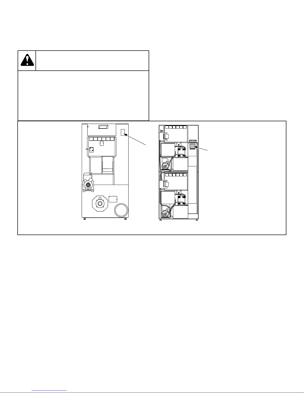
When calling or writing about your unit, PLEASE GIVE THE
MODEL AND SERIAL NUMBERS. The model and serial numbers are located on the serial plate. The serial plate will be in the
location shown in Figure 1 .
Date Purchased ______________________________
Model Number ______________________________
15 Part No. 70458301ENR10
TMB2098N_SVG
1
TMB1974N_SVG
1
Introduction
Serial Number _______________________________
Please include a copy of your bill of sale and any service receipts
you have.
WARNING
To reduce the risk of serious injury or death, DO
NOT repair or replace any part of the unit or attempt
any servicing unless specifically recommended in
the user-maintenance instructions or in published
user-repair instructions that you understand and
have the skills to carry out.
W329
If replacement parts are required, contact the source from where
you purchased your unit or call +1 (920) 748-3950 or +32 56 41
20 54 for the name and address of the nearest authorized parts
distributor.
1. Serial Plate
Figure 1
©
Copyright, Alliance Laundry Systems LLC -
DO NOT COPY or TRANSMIT
16 Part No. 70458301ENR10
Safety Information
Safety Information
Explanation of Safety Messages
Precautionary statements (“DANGER,” “WARNING,” and
“CAUTION”), followed by specific instructions, are found in this
manual and on machine decals. These precautions are intended
for the personal safety of the operator, user, servicer, and those
maintaining the machine.
DANGER
Indicates an imminently hazardous situation that, if
not avoided, will cause severe personal injury or
death.
WARNING
Indicates a hazardous situation that, if not avoided,
could cause severe personal injury or death.
CAUTION
Indicates a hazardous situation that, if not avoided,
may cause minor or moderate personal injury or
property damage.
Additional precautionary statements (“IMPORTANT” and
“NOTE”) are followed by specific instructions.
IMPORTANT: The word “IMPORTANT” is used to inform the reader of specific procedures where minor
machine damage will occur if the procedure is not followed.
NOTE: The word “NOTE” is used to communicate installation, operation, maintenance or servicing information that is important but not hazard related.
Important Safety Instructions
WARNING
To reduce the risk of fire, electric shock, serious injury or death to persons when using your tumbler,
follow these basic precautions.
W776
Save These Instructions
• Read all instructions before using the tumble dryer.
• Install the tumble dryer according to the INSTALLATION instructions. Refer to the EARTHING (grounding) instructions
for the proper earthing (grounding) of the tumble dryer. All
connections for electrical power, earthing (grounding) and gas
supply must comply with local codes and be made by licensed
personnel when required. It is recommended that the machine
be installed by qualified technicians.
• Do not install or store the tumble dryer where it will be exposed to water and/or weather. The tumble dryer cannot be
used in a closed room where the air supply is insufficient. If
necessary, ventilation grids must be installed in the doors or
the windows.
• This appliance must not be activated without lint/foam filter.
• When you perceive a gas odor, immediately switch off the gas
supply and ventilate the room. Do not switch on electrical appliances and do not pull electrical switches. Do not use
matches or lighters. Do not use a phone in the building. Warn
the fitter, and if so desired, the gas company, as soon as possible.
• To avoid fire and explosion, keep surrounding areas free of
flammable and combustible products. Regularly clean the
dryer drum and exhaust tube should be cleaned periodically
by competent maintenance personnel. Daily remove piled up
dust from filter and inside of filter compartment.
• Do not use or store flammable materials near this appliance.
• Do not dry articles that have been previously cleaned in,
washed in, soaked in or spotted with gasoline or machine oils,
vegetable or cooking oils, cleaning waxes or chemicals, drycleaning solvents, thinner or other flammable or explosive
substances as they give off vapors that could ignite, explode
or cause fabric to catch on fire by itself.
• Do not spray aerosols in the vicinity of this appliance while it
is in operation.
• Items such as foam rubber (latex foam), shower caps, waterproof textiles, rubber backed articles and clothes or pillows
filled with foam rubber pads should not be dried in the tumble
dryer. Do not use the appliance to dry materials with a low
melting temperature (PVC, rubber, etc.).
• Do not tumble fiberglass curtains and draperies unless the label says it can be done. If they are dried, wipe out the cylinder
with a damp cloth to remove particles of fiberglass.
• Do not allow children on or in the tumble dryer. This appliance is not intended for use by young children or infirm persons without supervision. Young children should be supervised to ensure that they do not play with the appliance.
• Do not reach into the tumble dryer if the cylinder is revolving.
• Use tumble dryer only for its intended purpose, drying fabrics. Always follow the fabric care instructions supplied by
the textile manufacturer and only use the dryer drum to dry
©
Copyright, Alliance Laundry Systems LLC -
DO NOT COPY or TRANSMIT
17 Part No. 70458301ENR10

Safety Information
textiles that have been washed in water. Only insert spin-dried
linen in the dryer.
• Always read and follow manufacturer’s instructions on packages of laundry and cleaning aids. Heed all warnings or precautions. To reduce the risk of poisoning or chemical burns,
keep them out of the reach of children at all times (preferably
in a locked cabinet).
• Do not use fabric softeners or products to eliminate static unless recommended by the manufacturer of the fabric softener
or product.
• Remove laundry immediately after tumble dryer stops.
• DO NOT operate the tumble dryer if it is smoking, grinding
or has missing or broken parts or removed guards or panels.
DO NOT tamper with the controls or bypass any safety devices.
• Tumble dryer will not operate with the loading door open. DO
NOT bypass the door safety switch to permit the tumble dryer
to operate with the door open. The tumble dryer will stop
tumbling when the door is opened. Do not use the tumble dryer if it does not stop tumbling when the door is opened or
starts tumbling without pressing or turning the START mechanism. Remove the tumble dryer from use and call for service.
• Tumble dryer(s) will not operate with lint panel open. DO
NOT bypass lint panel safety switch to permit the tumble dryer to operate with the lint panel open.
• Do not modify this appliance.
• Always clean the lint filter daily. Keep area around the exhaust opening and adjacent surrounding area free from the accumulation of lint, dust and dirt. The interior of the tumble
dryer and the exhaust duct should be cleaned periodically by
qualified service personnel.
• Solvent vapors from dry-cleaning machines create acids when
drawn through the heater of the drying unit. These acids are
corrosive to the tumble dryer as well as the laundry load being
dried. Be sure make-up air is free of solvent vapors.
• At the end of each working day, close off all main supplies of
gas, steam and current.
• Do not repair or replace any part of the tumble dryer, or attempt any servicing unless specifically recommended in the
user-maintenance instructions or in published user-repair instructions that the user understands and has the skills to carry
out. ALWAYS disconnect and lockout the electrical power to
the tumble dryer before servicing. Disconnect power by shutting off appropriate breaker or fuse.
• Before the tumble dryer is removed from service or discarded,
remove the door to the drying compartment and the door to
the lint compartment.
• Failure to install, maintain, and/or operate this tumble dryer
according to the manufacturer’s instructions may result in
conditions which can produce bodily injury and/or property
damage.
NOTE: The WARNINGS and IMPORTANT SAFETY INSTRUCTIONS appearing in this manual are not meant
to cover all possible conditions and situations that may
occur. Common sense, caution and care must be exercised when installing, maintaining, or operating the
tumble dryer.
Always contact your dealer, distributor, service agent or the manufacturer on any problems or conditions you do not understand.
©
Copyright, Alliance Laundry Systems LLC -
DO NOT COPY or TRANSMIT
18 Part No. 70458301ENR10

Specifications and Dimensions
Specifications and Dimensions
Specifications and Dimensions
Refer to machine serial plate for additional specifications.
Specifications 025 Series 030 Series 035 Series 055 Series
Heat dissipation of surface area exposed to
conditioned air: Btu/ft
[Joules/m2]
Noise level measured
during operation at operator position of 3.3
feet [1 meter] in front
of machine and 5.2 feet
[1.6 meters] from floor
Net Weight (approximate): Pounds [kg]
Standard Packaging
Weight: Pounds [kg]
Standard Packaging
Shipping Dimensions:
Inch [mm]
Slat Crate Packaging
Weight: Pounds [kg]
Slat Crate Shipping Dimensions: Inch [mm]
60 [681,392] 60 [681,392] 60 [681,392] 60 [681,392]
2
60 dBA 61 dBA 63 dBA 63 dBA
300 [137] 330 [150] 360 [163] 435 [197]
332 [151] 364 [165] 394 [179] 476 [216]
30 x 43 x 69 [762 x
1,092 x 1,753]
406 [184] 446 [202] 480 [218] 506 [230]
34.5 x 46 x 87.75 [876
x 1,168 x 1,229]
30 x 49 x 69 [762 x
1,245 x 1,753]
34.5 x 52 x 87.75
[876 x 1,321 x
2,229]
33 x 49 x 69 [838 x
1,245 x 1,753]
37.5 x 52 x 87.75 [953
x 1,321 x 2,229]
35.5 x 59 x 72 [902 x
1,499 x 1,829]
40 x 60 x 87.25 [1,016 x
1,524 x 2,216]
Cylinder Size:
Inch [mm]
Cylinder Capacity (dry
weight):
Pounds [kg]
Drive Motor: Horsepower [kW]
Fan Motor: Horsepower [kW]
©
Copyright, Alliance Laundry Systems LLC -
DO NOT COPY or TRANSMIT
26.5 x 24 [673 x 610] 26.5 x 30 [673 x
25 [11] 30 [13] 35 [16] 55 [24]
1/4 [0.1865] 1/4 [0.1865] 1/4 [0.1865] Nonreversing 1/2 [0.373]
1/4 [0.1865] 1/4 [0.1865] 1/4 [0.1865] 1/2 [0.373]
30 x 30 [762 x 762] 33 x 35 [838 x 889]
762]
Reversing 1/4 [0.1865]
Table continues...
19 Part No. 70458301ENR10
Specifications and Dimensions
Specifications 025 Series 030 Series 035 Series 055 Series
Maximum
Airflow:
C.F.M.
[l/sec]
Maximum
Static Back
Pressure:
Inch W.C.
[mbar, kPa]
50
Hertz
60
Hertz
50
Hertz
60
Hertz
Classic Line
430 [203]
Eco Line
250 [118]
Classic Line
500 [236]
Eco Line
300 [142]
Classic Line
0.6 [1.5, 0.15]
Eco Line
1.0 [2.5]
Classic Line
0.8 [2.0, 0.2]
Eco Line
1.4 [3.5, 0.35]
430 [203] Classic Line
550 [260]
Eco Line
450 [212]
500 [236] Classic Line
650 [307]
Eco Line
550 [260]
0.6 [1.5, 0.15] Classic Line
0.5 [1.3, 0.13]
Eco Line
0.7 [1.7]
0.8 [2.0, 0.2] Classic Line
0.6 [1.5, 0.15]
Eco Line
0.9 [2.2, 0.22]
600 [283]
700 [330]
0.5 [1.3, 0.13]
0.6 [1.5, 0.15]
Gas Models
Gas Connection 1/2 in. NPT 1/2 in. NPT 1/2 in. NPT 1/2 in. NPT
Gas Burner
Rating:
Btu/hr. [kW,
Mj/hr.]
50
Hertz
60
Hertz
Classic Line
64,000 [18.7, 67.5]
Eco Line
45,000 [13.2, 47.5]
Classic Line
64,000 [18.7, 67.5]
Eco Line
52,500 [15.4, 55.4]
Classic Line
73,000 [21.4, 77]
Eco Line
52,500 [15.4, 55.4]
Classic Line
73,000 [21.4, 77]
Eco Line
55,000 [16.1, 58.0]
Classic Line
90,000 [26.4, 95]
Eco Line
55,000 [16.1, 58.0]
Classic Line
90,000 [26.4, 95]
Eco Line
64,000 [18.7, 67.5]
Classic Line
102,000 [29.9, 107.6]
Eco Line
90,000 [26.4, 95.0]
Classic Line
112,000 [32.8, 118.2]
Eco Line
105,000 [30.8, 110.8]
Electric Models
Heating Element Rating:
400/50/310 kW Classic Line - 21
kW
Standard
Classic Line - 12 kW
Eco Line - 9 kW
Eco Line - 12 kW
Classic Line - 24 kW
Eco Line - 12 kW
Classic Line - 27 kW
Eco Line - 18 kW
Steam Models
©
Copyright, Alliance Laundry Systems LLC -
DO NOT COPY or TRANSMIT
Table continues...
20 Part No. 70458301ENR10
Specifications and Dimensions
Specifications 025 Series 030 Series 035 Series 055 Series
Steam Connection 3/4 in. NPT 3/4 in. NPT 3/4 in. NPT N/A
Steam Coil Rating at
134,700 [63.1] 134,700 [63.1] 166,000 [77.8] N/A
100 psig: Btu/hr.
[kg/hr.]
(recommended operating pressure 80-100
psig)
N/A = Not Applicable
NOTE: All machines are shipped with extra nipple to
convert to metric thread (from Standard).
Specifications T30 Series T45 Series
Noise level measured during operation at
66 dBA 67 dBA
operator position of 3.3 feet [1 meter] in
front of machine and 5.2 feet [1.6 meters]
from floor
Net Weight (approximate):
544 [247] 673 [305]
Pounds [kg]
Standard Packaging Weight: Pounds [kg] 582 [264] 718 [326]
Standard Packaging Shipping Dimen-
32.5 x 47 x 81 [826 x 1,194 x 2,057] 35.5 x 54 x 85 [902 x 1,372 x 2,159]
sions: Inch [mm]
Slat Crate Packaging Weight: Pounds
661 [300] 748 [339]
[kg]
Slat Crate Shipping Dimensions: Inch
37 x 50 x 87.75 [940 x 1,270 x 2,229] 40 x 57 x 87.25 [1,016 x 1,448 x 2,216]
[mm]
Cylinder Size:
30 x 26 [762 x 660] 33 x 30 [838 x 762]
Inch [mm]
Cylinder Capacity (dry weight):
2 x 30 [2 x 13] 2 x 45 [2 x 20]
Pounds [Kilograms]
Drive Motor**: Horsepower [kW] 1/4 [0.1865] 1/2 [0.373]
Fan Motor**: Horsepower [kW] 1/4 [0.1865] 1/2 [0.373]
Table continues...
©
Copyright, Alliance Laundry Systems LLC -
DO NOT COPY or TRANSMIT
21 Part No. 70458301ENR10
Specifications and Dimensions
Specifications T30 Series T45 Series
Maximum Airflow**:
C.F.M. [l/sec]
Maximum Static
Back Pressure*:
Inch W.C. [mbar,
kPa]
50 Hertz Classic Line
340 [160]
Eco Line
225 [106]
60 Hertz Classic Line
400 [189]
Eco Line
330 [156]
50 Hertz Classic Line
0.8 [2.0, 0.2]
Eco Line
1.2 [3.0]
60 Hertz Classic Line
0.9 [2.3, 0.23]
Eco Line
1.7 [4.2]
500 [236]
600 [283]
0.8 [2.0, 0.2]
0.9 [2.3, 0.23]
Gas Models
Gas Connection 1/2 in. NPT 1/2 in. NPT
Gas Burner Rating**:
Btu/hr. [kW,
Mj/hr.]
50 Hertz Classic Line
73,000 [21.4, 77]
Eco Line
52,500 [15.4, 55.4]
60 Hertz Classic Line
73,000 [21.4, 77]
Eco Line
55,000 [16.1, 58.0]
Classic Line
87,000 [25.5, 91.8]
Eco Line
74,000 [21.7, 78.1]
Classic Line
95,000 [27.8, 100.2]
Eco Line
80,000 [23.5, 84.4]
Electric Models
Heating Element Rating**: Classic Line - 21 kW
N/A
Eco Line - 12 kW
Steam Models
Steam Connection 3/4 in. NPT N/A
©
Copyright, Alliance Laundry Systems LLC -
DO NOT COPY or TRANSMIT
Table continues...
22 Part No. 70458301ENR10
Specifications T30 Series T45 Series
TMB2292N_SVG
JI
K
L
G
H
B
C
D
E
F
A
Specifications and Dimensions
Steam Coil Rating at 100 psig**:
111,000 [52] N/A
Btu/hr. [kg/hr.] (recommended operating
pressure 80-100 psig)
* with both tumble dryers running
** for each tumble dryer
N/A = Not Applicable
NOTE: All machines are shipped with extra nipple to
convert to metric thread (from Standard).
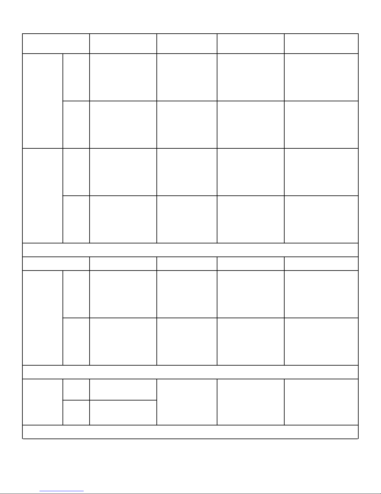
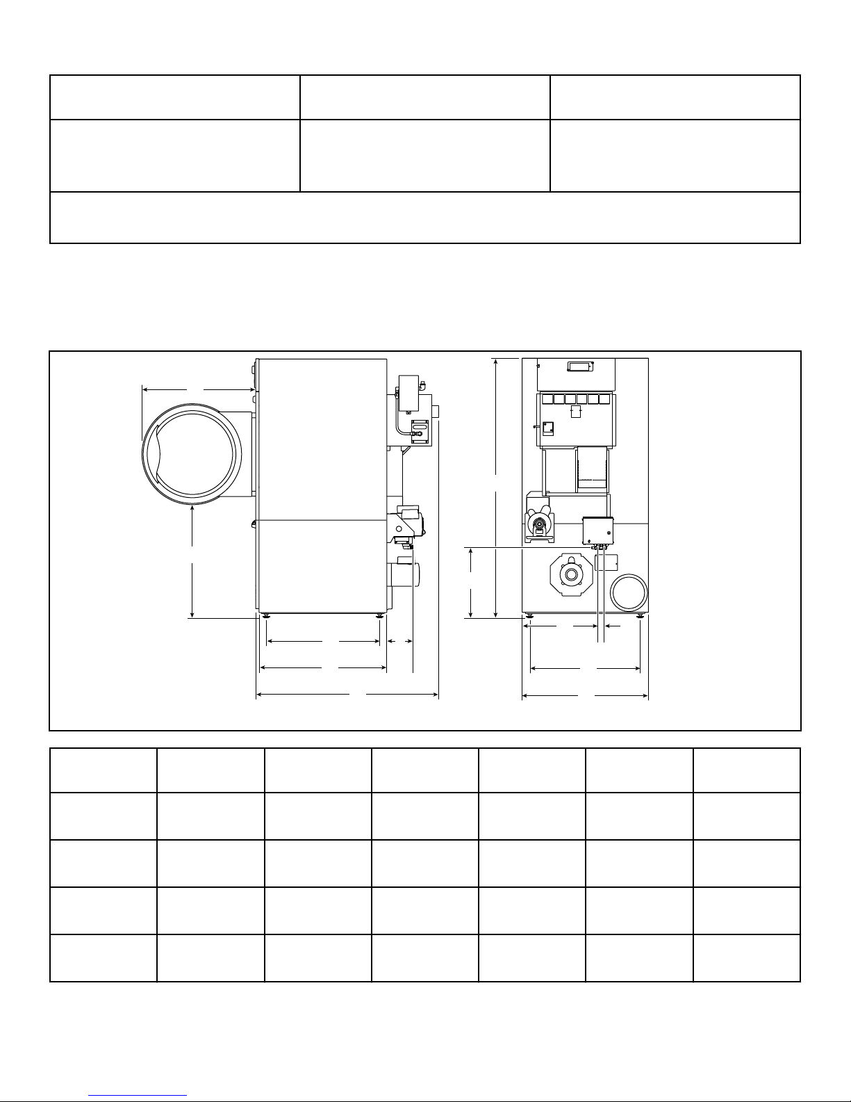
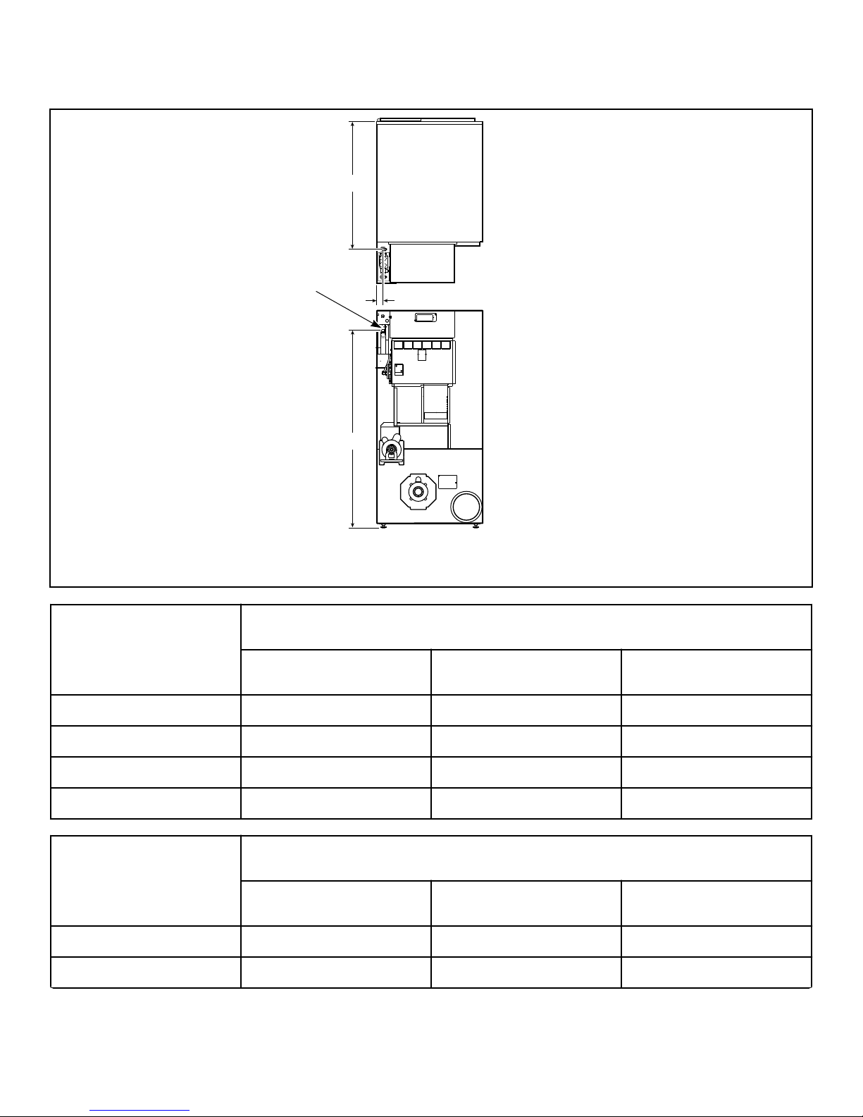
Cabinet Dimensions – 025, 030, 035 and 055 Series
Models A B C D E F*
025 Series 26.25 in. [667
mm]
030 Series 26.25 in. [667
mm]
035 Series 28 in. [711
mm]
055 Series 31.88 in. [810
mm]
©
Copyright, Alliance Laundry Systems LLC -
DO NOT COPY or TRANSMIT
27.5 in. [669
mm]
27.5 in. [669
mm]
27.5 in. [669
mm]
26.87 in. [682.5
mm]
22.35 in. [568
mm]
28.35 in. [720
mm]
28.35 in. [720
mm]
33.75 in.
[857.25 mm]
23 Part No. 70458301ENR10
25.75 in. [654
mm]
31.75 in. [806
mm]
31.75 in. [806
mm]
38.25 in. [971.5
mm]
40.875 in.
[1,038 mm]
46.875 in.
[1,191 mm]
46.875 in.
[1,191 mm]
53.62 in. [1,365
mm]
6.53 in. [166
mm]
6.53 in. [166
mm]
6.53 in. [166
mm]
6.53 in. [166
mm]
TMB2421N_SVG
J
I
K
D
E
H
F
G
A
C
B
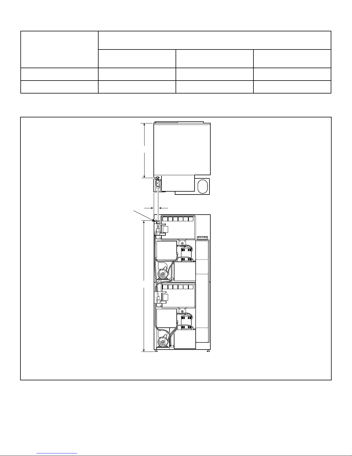
Specifications and Dimensions
Models G H* I* J* K L
025 Series 63.875 in.
[1,622 mm]
030 Series 63.875 in.
[1,622 mm]
035 Series 63.875 in.
[1,622 mm]
055 Series 66.72 in.
[1,694.7 mm]
16.48 in. [419
mm]
16.48 in. [419
mm]
16.48 in. [419
mm]
17.75 in. [451
mm]
15.41 in. [391
mm]
15.41 in. [391
mm]
19.59 in. [497.5
mm]
18.65 in. [474
mm]
* Fire suppression system optional - may not be on machine.
NOTE: Facia panels available to increase height of
models to 72.25 inches [1,835 mm] and 76.25 inches
[1,938 mm].
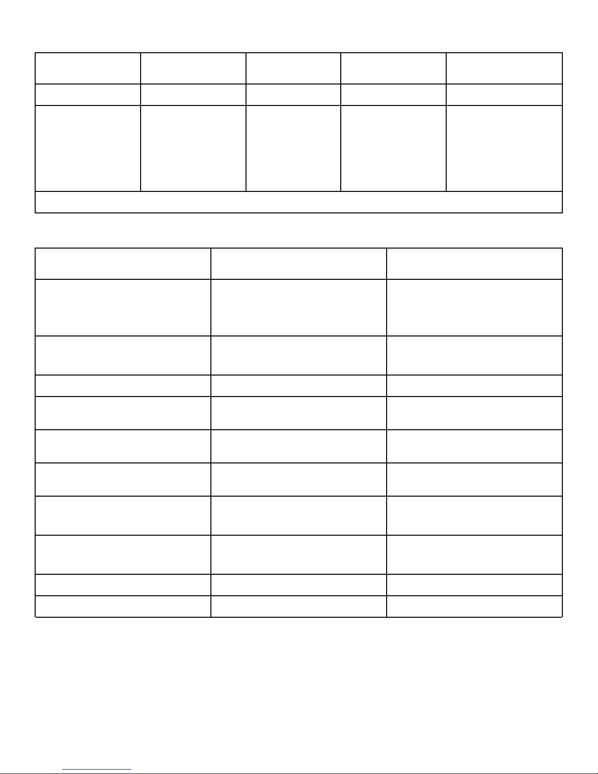
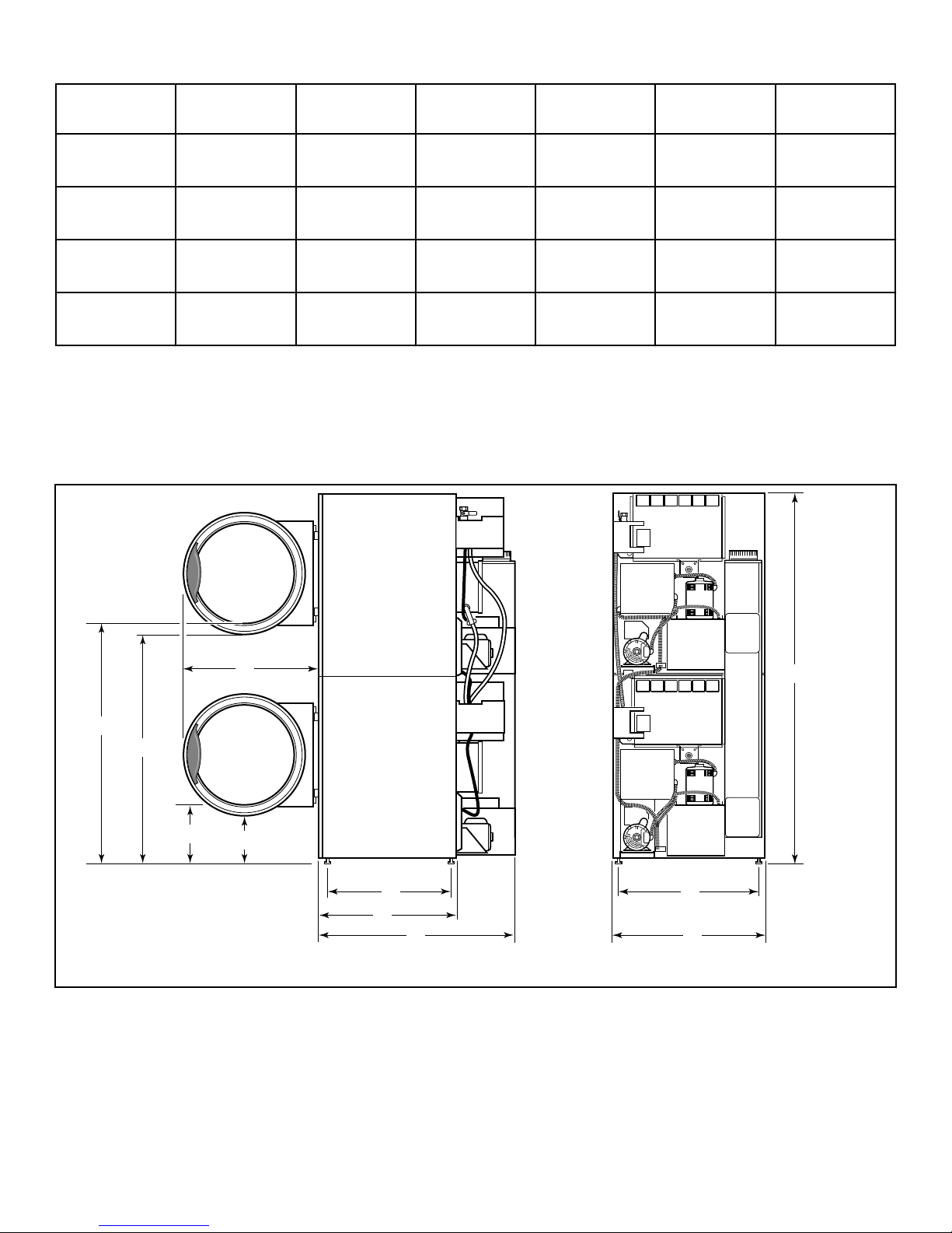
Cabinet Dimensions – T30 and T45 Series
1.59 in. [40
mm]
1.59 in. [40
mm]
1.59 in. [40
mm]
1.59 in. [40
mm]
24.64 in. [626
mm]
24.64 in. [626
mm]
27.38 in. [695
mm]
30.5 in. [774.7
mm]
28 in. [711
mm]
28 in. [711
mm]
31.5 in. [800
mm]
34.5 in. [876
mm]
©
Copyright, Alliance Laundry Systems LLC -
DO NOT COPY or TRANSMIT
24 Part No. 70458301ENR10
TMB2132N_SVG
A
B
Specifications and Dimensions
Models A B C D E
T30 Series 28 in. [711 mm] 49 in. [1,245 mm] 48.25 in. [1,226
11.4 in. [290 mm] 10.7 in. [272 mm]
mm]
T45 Series 31.88 in. [810
mm]
50.4 in. [1,280
mm]
49.3 in. [1,252
mm]
10.3 in. [262 mm] 9.3 in. [236 mm]
Models F G H I J K
T30 Series 25.02 in. [636
mm]
T45 Series 29.37 in. [746
mm]
28.67 in. [728
mm]
32.7 in. [831
mm]
42.76 in. [1,086
mm]
48.62 in. [1,235
mm]
27.38 in. [695
mm]
30.50 in. [775
mm]
31.5 in. [800
mm]
34.5 in. [876
mm]
NOTE: To meet ADA compliance, install a 4 inch [102
mm] riser on T30 models only.
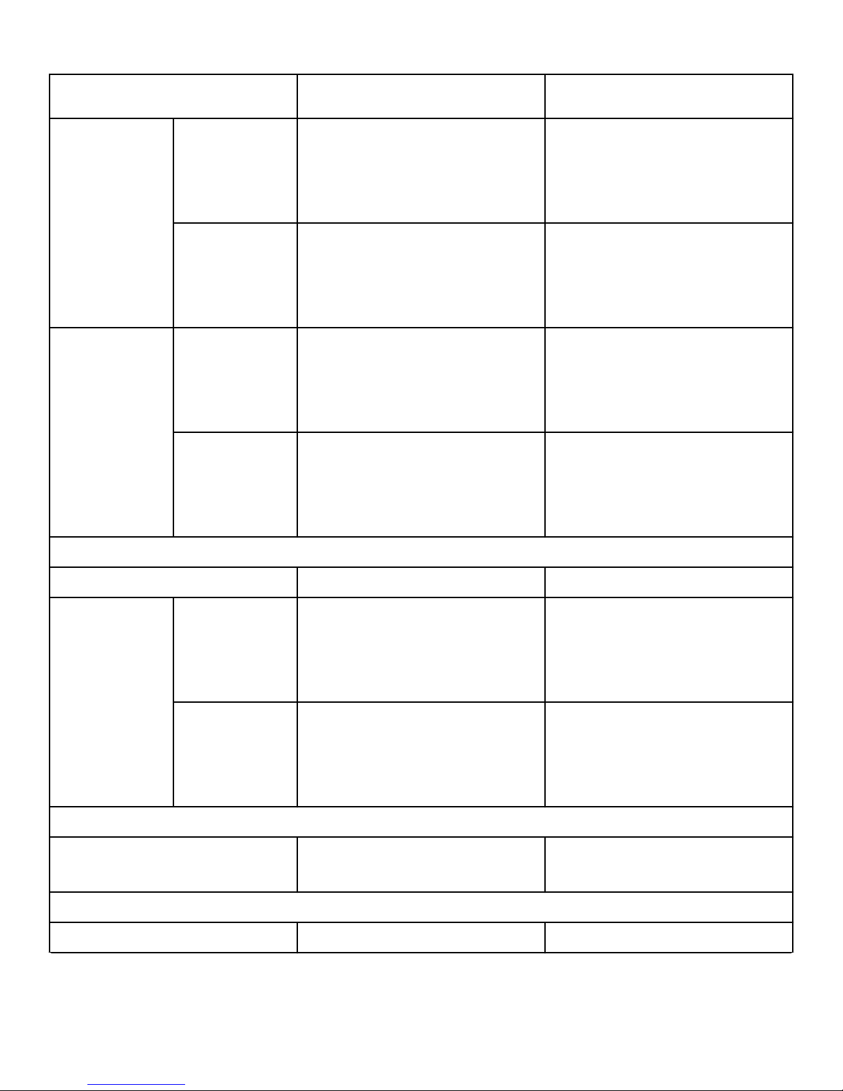
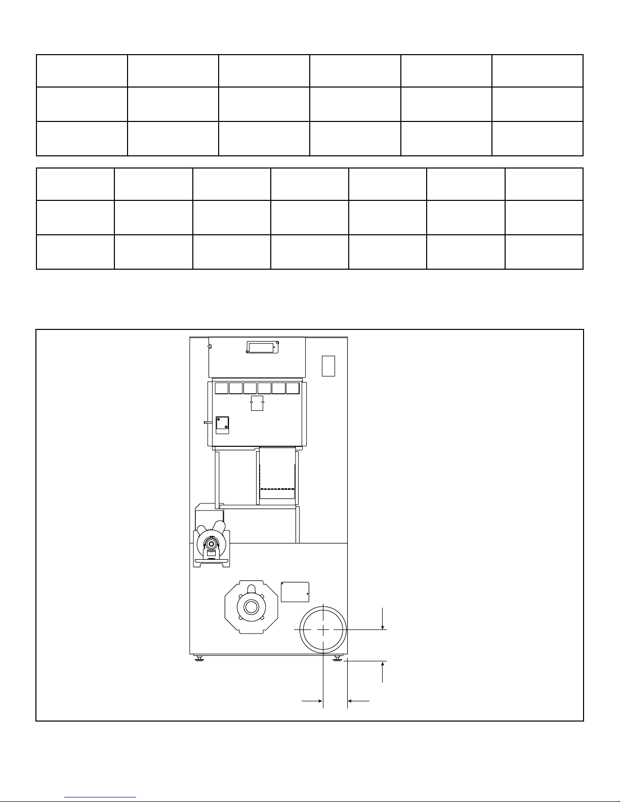
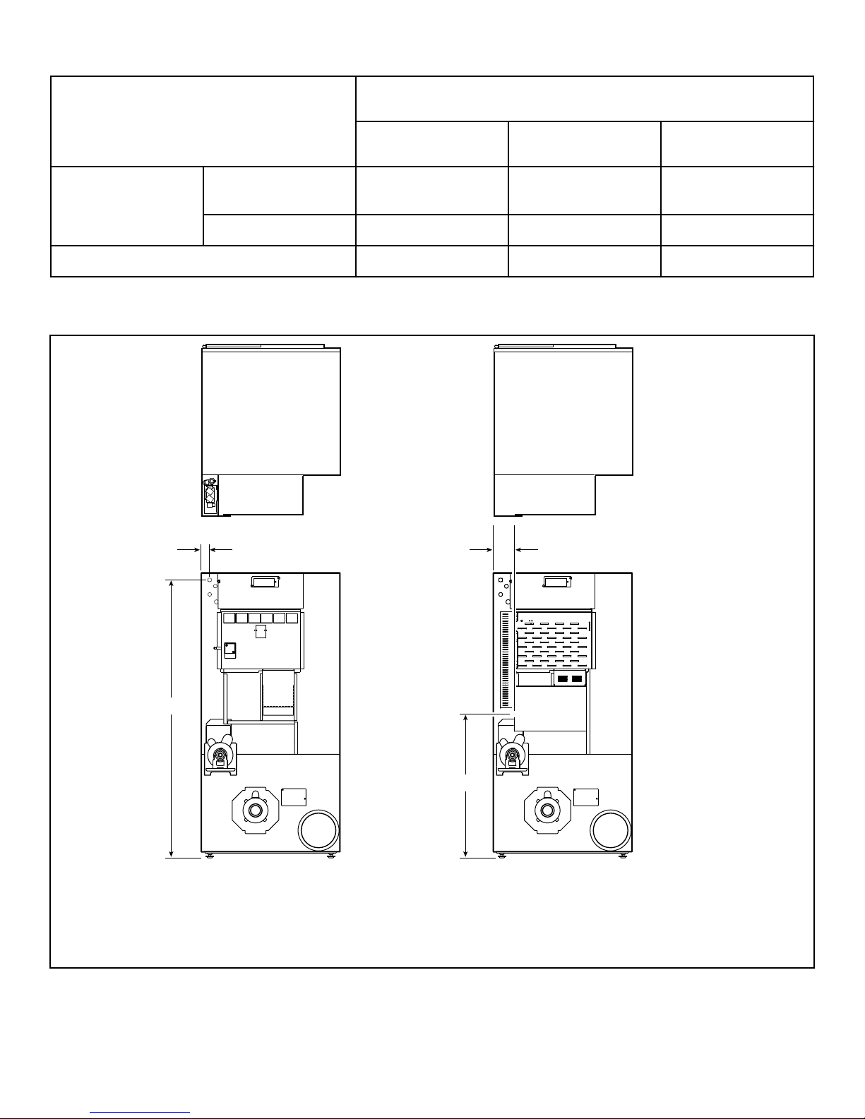
Exhaust Outlet Locations – 025, 030, 035 and 055 Series
76.25 in. [1,937
mm]
81.25 in. [2,064
mm]
©
Copyright, Alliance Laundry Systems LLC -
DO NOT COPY or TRANSMIT
25 Part No. 70458301ENR10

Specifications and Dimensions
Rear Exhaust
Models
025 Series Classic Line
Diameter A B
3.875 in. [99 mm] 4.625 in. [117 mm]
6 in. [152 mm]
Eco Line
4 in. [102 mm]
030 Series 6 in. [152 mm] 3.875 in. [99 mm] 4.625 in. [117 mm]
035 Series Classic Line
4.875 in. [124 mm] 5.625 in. [143 mm]
8 in. [203 mm]
Eco Line
6 in. [152 mm]
055 Series 8 in. [203 mm] 4.808 in. [122 mm] 6.156 in. [156.3 mm]
©
Copyright, Alliance Laundry Systems LLC -
DO NOT COPY or TRANSMIT
26 Part No. 70458301ENR10
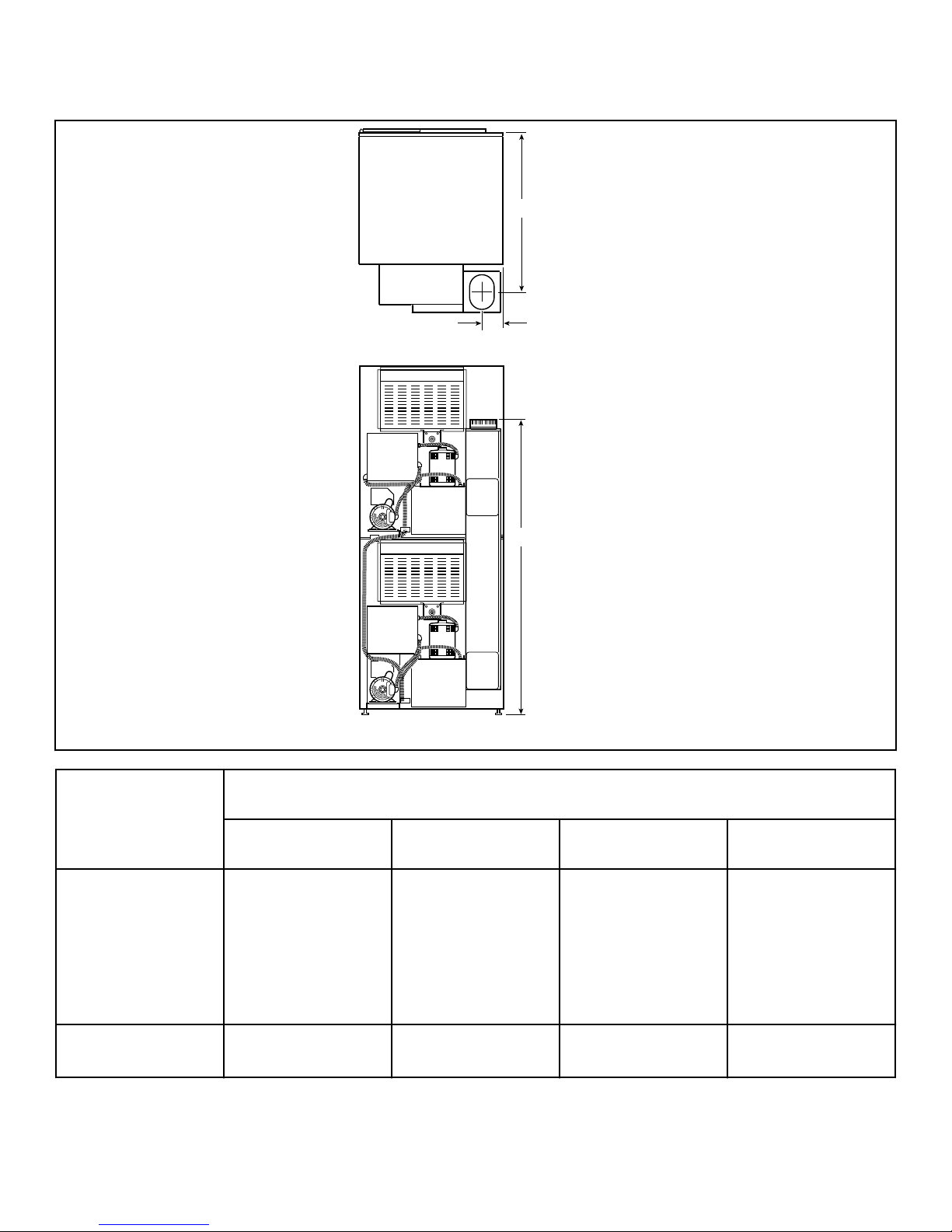
Exhaust Outlet Locations – T30 and T45 Series
TMB1969N_SVG
A
C
B
Specifications and Dimensions
Rear Exhaust
Models
Diameter A B C
T30 Series Classic Line
Elliptical Fits 8 in. [203
mm]
Eco Line
Round Fits 6 in. [152
mm]
T45 Series Elliptical Fits 10 in.
[254 mm]
36.54 in. [928 mm] 4.25 in. [108 mm] 62.42 in. [1,585 mm]
40.88 in. [1,038 mm] 4.75 in. [121 mm] 66.00 in. [1,676 mm]
©
Copyright, Alliance Laundry Systems LLC -
DO NOT COPY or TRANSMIT
27 Part No. 70458301ENR10
TMB2106N_SVG
A
C
B
1
Specifications and Dimensions
Gas Connection Locations – 025, 030, 035 and 055 Series
1. 1/2 in. NPT
Gas Connection – CE and Australian Units
Models
A B C
25 Series 59 in. [1,500 mm] 1.5 in. [38.1 mm] 29 in. [737 mm]
30 Series 59 in. [1,500 mm] 1.5 in. [38.1 mm] 35 in. [889 mm]
35 Series 59 in. [1,500 mm] 2.5 in. [64 mm] 35 in. [889 mm]
55 Series 59 in. [1,500 mm] 2.5 in. [64 mm] 35 in. [889 mm]
Models
Gas Connection – Non-CE and Non-Australian Units
A B C
25 Series 57 in. [1,450 mm] 2.5 in. [64 mm] 35.5 in. [927 mm]
30 Series 57 in. [1,450 mm] 2.5 in. [64 mm] 43 in. [1,092 mm]
©
Copyright, Alliance Laundry Systems LLC -
DO NOT COPY or TRANSMIT
Table continues...
28 Part No. 70458301ENR10
Gas Connection – Non-CE and Non-Australian Units
TMB1970N_SVG
C
B
A
1
Specifications and Dimensions
Models
A B C
35 Series 57 in. [1,450 mm] 4 in. [101.6 mm] 43 in. [1,092 mm]
55 Series 55.285 in. [1,404 mm] 1.621 in. [41.17 mm] 46.75 in. [1,187.45 mm]
Gas Connection Locations – T30 and T45 Series
1. 1/2 in. NPT
©
Copyright, Alliance Laundry Systems LLC -
DO NOT COPY or TRANSMIT
29 Part No. 70458301ENR10
TMB2204N_SVG
B
C
D
A
21
Specifications and Dimensions
Gas Connection
Models
T30 Series Non-CE and Non-Aus-
A B C
75.20 in. [1,910 mm] 1.74 in. [44 mm] 36.84 in. [936 mm]
tralian
CE and Australian 75.28 in. [1,912 mm] 2.5 in. [64 mm] 30.60 in. [777 mm]
T45 Series 78.75 in. [2,000 mm] 4.12 in. [105 mm] 42.88 in. [1,089 mm]
Electrical Connection Locations – 025, 030, 035 and 055 Series
1. Gas and Steam
2. Electric
©
Copyright, Alliance Laundry Systems LLC -
DO NOT COPY or TRANSMIT
30 Part No. 70458301ENR10
 Loading...