

Page 1
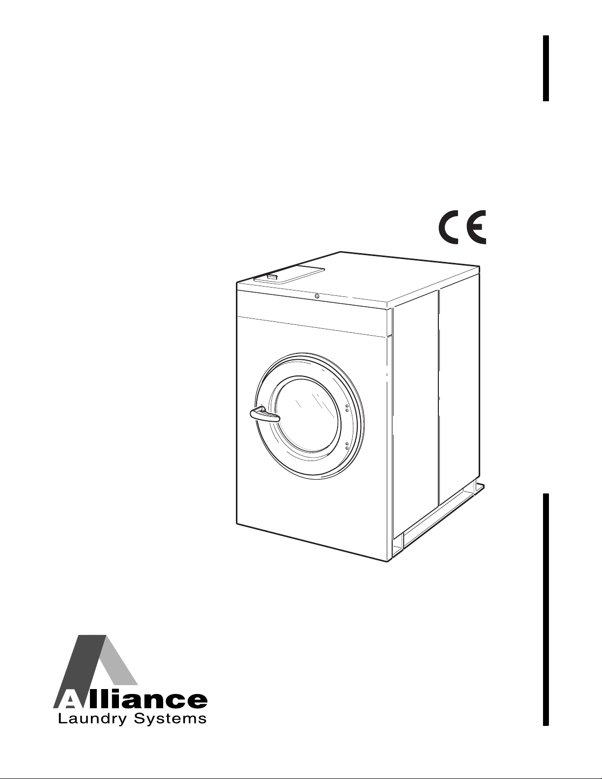
Washer-Extractors
Cabinet Hardmount Operating Instructions
Basic Installation/Operation
Keep These Instructions for Future Reference.
(If this machine changes ownership, this manual must accompany machine.)
www.comlaundry.com
CHM1772C
Part No. F8321401R1EN
April 2010
Page 2

Page 3

Basic Installation/Operation
Table of
Content s
Safety Information.............................................................................. 2
Important Safety Instructions ............................................................... 2
Safety Decals........................................................................................ 4
Operator Safety....................................................................... ..... ......... 5
Specifications and Dimensions........................................................... 6
Dimensional Clearances ....................................................................... 10
Dimensions........................................................................................... 11
20, 30, 40, 60 and 80 Models........................................................... 11
125 Model........................................................................................ 13
Electrical Specifications ....................................................................... 14
Operation............................................................................................. 17
Operating Instructions, Vend Models Only.......................................... 18
Operating Instructions, OPL Models Only........................................... 20
Disposal of Unit................................................................................... 22
© Copyright 2010, Alliance Laundry Systems LLC
All rights reserved. No part of the contents of this book may be reproduced or transmitted in any form or by any
means without the expressed written consent of the publisher.
F8321401 (EN)
© Copyright, Alliance Laundry Systems LLC – DO NOT COPY or TRANSMIT
1
Page 4
Basic Installation/Operation
DANGER indicates the presence of a
hazard that will cause severe personal
injury, death, or substantial property
damage if the danger is ignored.
DANGER
WARNING indicates the presence of a
hazard that can cause severe personal
injury, death, or substantial property
damage if the warning is ignored.
WARNING
CAUTION indicates the presence of a
hazard that will or can cause minor
personal injury or property damage if the
caution is ignored.
CAUTION
To reduce the risk of fire, electric shock,
serious injury or death to persons when
using your washer, follow these basic
precautions:
W023
WARNING
Safety Information
Precautionary statements (“DANGER,” “WARNING,”
and “CAUTION”), followed by specific instructions,
are found in this manual and on machine decals. These
precautions are intended for the personal safety of the
operator, user, servicer, and those maintaining the
machine.
Important Safety Instructions
1. Read all instructions before using the washer.
2. Refer to the
INSTALLATION Manual for the proper
grounding of the washer.
3. Do not wash textiles that have been previously
cleaned in, washed in, soaked in, or spotted with
gasoline, kerosene, waxes, cooking oils,
dry-cleaning solvents, or other flammable or
explosive substances as they give off vapors that
could ignite or explode.
4. Do not add gasoline, dry-cleaning solvents, or
other flammable or explosive substances to the
wash water. These substances give off vapors that
could ignite or explode.
GROUNDING INSTRUCTIONS in the
Additional precautionary statements (“IMPORTANT”
and “NOTE”) are followed by specific instructions.
IMPORTANT: The word “IMPORT ANT” is used
to inform the reader of specific procedures where
minor machine damage will occur if the procedure
is not followed.
NOTE: The word “NOTE” is used to communicate
installation, operation, maintenance or servicing
information that is important but not hazard
related.
5. Under certain conditions, hydrogen gas may be
produced in a hot water system that has not been
used for two weeks or more. HYDROGEN GAS
IS EXPLOSIVE. If the hot water system has not
been used for such a period, before using a
washing machine or combination washer-dryer,
turn on all hot water faucets and let the water
flow from each for several minutes. This will
release any accumulated hydrogen gas. The gas
is flammable; do not smoke o r us e an open flam e
during this time.
6. Do not allow children to play on or in the washer .
Close supervision of children is necessary when
the washer is used near children. This is a safety
rule for all appliances.
7. Before the washer is removed from service or
discarded, remove the door to the washing
compartment.
8. Do not reach into the washer if the wash drum is
moving.
2
© Copyright, Alliance Laundry Systems LLC – DO NOT COPY or TRANSMIT F8321401 (EN)
Page 5

Basic Installation/Operation
9. Do not install or store the washer where it will be
exposed to water and/or weather.
10. Do not tamper with the controls.
11. Do not repair or replace any part of the washer , or
attempt any servicing unless specifically
recommended in the user-maintenance instructions
or in published user-repair instructions that the
user understands and has the skills to carry out.
12. T o reduce the risk of an electric shock or fire, DO
NOT use an extension cord or an adapter to
connect the washer to the electrical power
source.
13. Use washer only for its intended purpose,
washing textiles.
14. Never wash machine parts or automotive parts in
the machine. This could result in serious damage
to the basket.
15. ALWAYS disconnect the washer from electrical
supply before attempting any service. Disconnect
the power cord by grasping the plug, not the cord.
16. Install the washer according to the
INSTALLATION INSTRUCTIONS. All
connections for water, drain, electrical power and
grounding must comply with local codes and be
made by licensed personnel when required.
17. To reduce the risk of fire, textiles which have
traces of any flammable substances such as
vegetable oil, cooking oil, machine oil,
flammable chemicals, thinner, etc., or anything
containing wax or chemicals such as in mops and
cleaning cloths, must not be put into the washer.
These flammable substances may cause the
fabric to catch on fire by itself.
18. Do not use fabric softeners or products to
eliminate static unless recommended by the
manufacturer of the fabric softener or product.
19. Keep washer in good condition. Bumping or
dropping the washer can damage safety features.
If this occurs, have washer checked by a
qualified service person.
20. If the supply cord is damaged, it must be replaced
by a special cord or assembly available from the
service agent.
21. Be sure water connections have a shut-off valve
and that fill hose connections are tight. CLOSE
the shut-off valves at the end of each wash day.
22. Loading door MUST BE CLOSED any time the
washer is to fill, tumble or spin. DO NOT bypass
the loading door switch by permitting the washer
to operate with the loading door open.
23. Always read and follow manufacturer’s
instructions on packages of laundry and cleaning
aids. Heed all warnings or precautions. T o reduce
the risk of poisoning or chemical burns, keep
them out of the reach of children at all times
(preferably in a locked cabinet).
24. Always follow the fabric care instructions
supplied by the textile manufacturer.
25. Never operate the washer with any guards and/or
panels removed.
26. DO NOT operate the washer with missing or
broken parts.
27. DO NOT bypass any safety devices.
28. Failure to install, maintain, and/or operate this
washer according to the manufacturer’s
instructions may result in conditions which can
produce bodily injury and/or property damage.
NOTE: The WARNING and IMPORTANT
SAFETY INSTRUCTIONS appearing in this
manual are not meant to cover all possible
conditions and situations that may occur. Common
sense, caution and care must be exercised when
installing, maintaining or operating the washer.
Any problems or conditions not understood should be
reported to the dealer, distributor, service agent or the
manufacturer.
F8321401 (EN)
© Copyright, Alliance Laundry Systems LLC – DO NOT COPY or TRANSMIT
3
Page 6
Basic Installation/Operation
This machine must be installed, adjusted,
and serviced by qualified electrical
maintenance personnel familiar with the
construction and operation of this type of
machinery. They must also be familiar
with the potential hazards involved.
Failure to observe this warning may result
in personal injury and/or equipment
damage, and may void the warranty.
SW004
WARNING
Install the machine on a level floor of
sufficient strength. Failure to do so may
result in conditions which can produce
serious injury, death and/or property
damage.
W703
WARNING
Be careful around the open door,
particularly when loading from a level
below the door. Impact with door edges
can cause personal injury.
SW025
CAUTION
Never touch internal or external steam
pipes, connections, or components.
These surfaces can be extremely hot and
will cause severe burns. The steam must
be turned off and the pipe, connections,
and components allowed to cool before
the pipe can be touched.
SW014
WARNING
IMPORTANT: Ensure that the recommended
clearances for inspection and maintenance
are provided. Never allow the inspection and
maintenance space to be blocked.
Safety Decals
Safety decals appear at crucial locations on the
machine. Failure to maintain legible safety decals
could result in injury to the operator or service
technician.
To provide person al safety and keep the machine in
proper working order, follow all maintenance and
safety procedures presented in this manual. If
questions regarding safety arise, contact the
manufacturer immediately.
Use manufacturer-authorized spare parts to avoid
safety hazards.
4
© Copyright, Alliance Laundry Systems LLC – DO NOT COPY or TRANSMIT
F8321401 (EN)
Page 7
Basic Installation/Operation
NEVER insert hands or objects into
basket until it has completely stopped.
Doing so could result in serious injury.
SW012
WARNING
Never operate the machine with a
bypassed or disconnected balance
system. Operating the machine with
severe out-of-balance loads could result
in personal injury and serious equipment
damage.
SW039
WARNING
Operator Safety
To ensure the safety of machine operators, the
following maintenance checks must be performed
daily:
1. Prior to operating the machine, verify that all
warning signs are present and legible. Missing or
illegible signs must be replaced immediately.
Make certain that spares are available.
2. Check door interlock before starting operation of
the machine:
a. Attempt to start the machine with the door
open. The machine should not start with the
door open.
b. Close the door without locking it and attempt
to start the machine. The machine should not
start with the door unlocked.
Do not bypass any safety devices in the machine.
c. Close and lock the door and start a cycle.
Attempt to open the door while the cycle is in
progress. The door should not open.
If the door lock and interlock are not functioning
properly, call a service technician.
3. Do not attempt to operate the machine if any of
the following conditions are present:
a. The door does not remain securely locke d
during the entire cycle.
b. Excessively high water level is evident.
c. Machine is not connected to a properly
grounded circuit.
F8321401 (EN)
© Copyright, Alliance Laundry Systems LLC – DO NOT COPY or TRANSMIT
5
Page 8
Basic Installation/Operation
Specifications and Dimensions
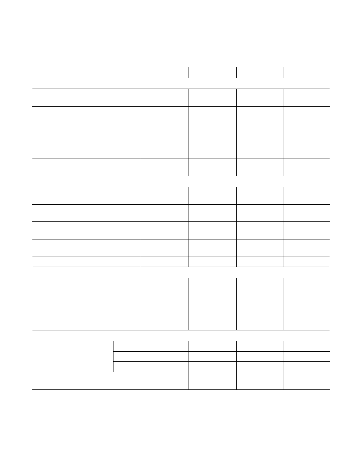
Specification 20 30 40 60
Weight and Shipping Information
2 Speed Models
Net weight, lbs. (kg) 387
(176)
Domestic shipping weight, lbs. (kg) 420
(191)
Domestic shipping volume, ft
Export shipping weight lbs., (kg) 475
Export shipping volume, ft
Wash Cylinder Information
Cylinder diameter,
in. (mm)
Cylinder depth, in. (mm) 13.75
Cylinder volume, ft
Perforation size, in. (mm) 0.188
Perforation open area, % 17 23 17.5 18
3
(l) 2.76
3
(m3) 30.5
(0.86)
(215)
3
(m3) 36.2
(1.03)
(533)
(349)
(78.1)
(4.76)
21
489
(222)
530
(240)
40.75
(1.15)
593
(269)
49.9
(1.41)
24
(610)
16
(406)
4.19
(118.6)
0.188
(4.76)
692
(314)
734
(333)
50
(1.42)
816
(370)
60
(1.70)
26.25
(667)
20.25
(514)
6.34
(180)
0.188
(4.76)
812
(368)
854
(387)
64
(1.81)
948
(430)
75.8
(2.15)
30
(762)
22
(559)
9.00
(255)
0.188
(4.76)
Door Opening Information
Door opening diameter, in. (mm)
Height of door bottom above floor, in. (mm)
Height of door opening above floor, in. (mm)
Power Consumption
Average power used per cycle,
kW-hr
Average HVAC load, Btu/hr. (Kcal./Hr.) 425
No load
Sheets
Towels
11.63
(295)
14.38
(365)
17.19
(437)
0.06 0.13 0.196 0.25
0.10 0.14 0.195 0.26
0.11 0.16 0.213 0.33
(107)
Table 1 (Continued)
14.34
(364)
14
(356)
17
(431)
463
(117)
16.25
(413)
14.5
(368)
19
(483)
510
(129)
16.25
(413)
15
(381)
18.5
(470)
700
(176)
6
© Copyright, Alliance Laundry Systems LLC – DO NOT COPY or TRANSMIT F8321401 (EN)
Page 9

Basic Installation/Operation
Table 1 (Continued)
2 Speed Models (Continued)
Specification 20304060
Drive Train Information
Number of motors in drive train 1 1 1 1
Wash/reverse power, HP (kW) 0.15
(0.11)
High extract power, HP (kW) .74
(0.55)
0.24
(0.18)
1.34
(1.00)
0.40
(0.30)
1.8
(1.3)
0.55
(0.41)
2.7
(2.01)
Cylinder Speeds
Wash/reverse speed, RPM 57 49 51 44
High extract speed, RPM 528 464 491 469
Centrifugal Force Data
Wash/reverse centrifugal force, Gs 0.9 0.8 0.8 0.9
High extract centrifugal force, Gs 80.3 72.1 78.1 85.4
Direct Steam Heating (Optional)
Steam inlet connection size,
in. (mm)
N/A N/A 1/2
(13)
1/2
(13)
Number of steam inlets N/A N/A 1 1
Steam required to raise bath water
temperature 10°F (10°C), lbs. (kg)
LOW N/A N/A 2.09
(0.84)
MED N/A N/A 2.40
(1.15)
3.6
(0.895)
4.4
(1.384)
HIGH N/A N/A 2.84
Average steam use per cycle,
bhp (kg)
N/A 0.73
(6.9)
(1.48)
1.43
(12.2)
(1.916)
(15.4)
Electrical Heating (Optional)
Total electrical heating capacity,
kW
Input Voltage
200V
240V
380V
415V
480V
5.4 5.4 10.8 10.8
7.8 7.8 15.6 15.6
6.5 6.5 13.0 13.0
7.8 7.8 15.5 15.5
N/A N/A 15.6 15.6
Electrical heating elements 3 3 6 6
Electrical heat element size, kW 2.6 2.6 2.6 2.6
Table 1
F8321401 (EN)
© Copyright, Alliance Laundry Systems LLC – DO NOT COPY or TRANSMIT
5.5
2.32
7
Page 10

Basic Installation/Operation
Variable-Speed and Fixed-Speed Models
Specification 20 30 40 60 80 125
Weight and Shipping Information
Net weight, lbs. (kg) 386
(175)
Domestic shipping weight, lbs. (kg) 424
(191)
Domestic shipping volume, ft
3
(m3)27
(0.76)
Export shipping weight, lbs. (kg) 476
(215)
Export shipping volume, ft
3
(m3) 36.7
(1.04)
Wash Cylinder Information
Cylinder diameter, in. (mm) 21
(533)
Cylinder depth, in. (mm) 13.75
(349)
Cylinder volume, ft
3
(l) 2.76
(78.1)
Perforation size, in. (mm) 0.188
(4.76)
Perforation open area, % 17 23 17.5 18 18 24
498
(226)
545
(245)
34.4
(0.98)
588
(267)
49.5
(1.40)
24
(610)
16
(406)
4.19
(118)
0.188
(4.76)
706
(321)
744
(338)
43.6
(1.24)
846
(385)
65.6
(1.86)
26.25
(667)
20.25
(514)
6.34
(180)
0.188
(4.76)
773
(350)
824
(373)
52.2
(1.48)
1020
(463)
74.7
(3.35)
30
(762)
22
(559)
9.00
(255)
0.188
(4.76)
1374
(623)
1461
(663)
102.2
(2.89)
1573
(714)
118.3
(3.35)
36
(914)
22
(559)
12.4
(354)
0.188
(4.76)
(1044)
(1081)
(1130)
(1060)
2301
2384
163
(4.3)
2492
173
(4.8)
42
24
(609)
19.2
(544)
0.188
(4.76)
Door Opening Information
Door opening size, in. (mm) 11.63
(295)
Height of door bottom above floor, in. (mm) 14.38
(365)
Height of door opening bottom, in. (mm) 17.19
(437)
14.34
(364)
14
(356)
17
(431)
16.25
(413)
14.5
(368)
18
(457)
16.25
(413)
18.25
(445)
18.5
(470)
17.75
(451)
N/A 21.63
(549)
20
(508)
29
(737)
30.25
(768)
Estimated Building Heat Load
Average power used per cycle, kW-hr 0.05 0.07 0.34 0.21 0.40 0.60
A verage HVAC load, Btu/hr 400 450 510 750 950 1200
Drive Train Information
Number of motors in drive train 1 1 1 1 1 1
Drive motor power, HP (kW) 1
(.75)
1
(.75)
2
(1.7)
3
(2.2)
5
(3.7)
7.5
(5.6)
Table 2 (Continued)
8
© Copyright, Alliance Laundry Systems LLC – DO NOT COPY or TRANSMIT
F8321401 (EN)
Page 11

Basic Installation/Operation
Table 2 (Continued)
Variable-Speed and Fixed-Speed Models (Continued)
Specification 20 30 40 60 80 125
Cylinder Speeds
Gentle wash/reverse speed, RPM 292726262226
Wash/reverse speed, RPM 52 52 46 43 40 37
Distribution speed, RPM 92 92 82 77 70 65
Low extract speed, RPM 366 366 328 307 280 260
Medium extract speed, RPM
(Not available on Electronic Control models.)
High extract speed, RPM 686 686 613 574 524 485
Centrifugal Force Data
Gentle wash centrifugal force, Gs 0.25 0.25 0.25 0.25 0.25 0.43
Wash/reverse centrifugal force, Gs 0.8 0.8 0.8 0.8 0.8 0.8
Distribution centrifugal force, Gs 2.5 2.5 2.5 2.5 2.5 2.6
Low extract centrifugal force, Gs 40 40 40 40 40 40
Medium extract centrifugal force, Gs 85 85 85 85 85 85
High extract centrifugal force, Gs 140 140 140 140 140 140
534 534 478 447 408 378
Direct Steam Heating (Optional)
Steam inlet connection size,
in. (mm)
Number of steam inlets N/A N/A 1 1 1 1
Steam required to raise bath water
temperature 10°F (6°C), lbs. (kg)
Average steam use per cycle, bhp (kg) N/A 0 .73
Electrical Heating (Optional)
Total electrical heating capacity, kW
Electrical heating elements
Electrical heat element size, kW
LOW N/A N/A 2.09
MED N/A N/A 2.40
HIGH N/A N/A 2.84
Input Voltage
200V 5.4 5.4 10.8 10.8 21.7 N/A
240V 7.8 7.8 15.6 15.6 31.2 N/A
380V 6.5 6.5 13.0 13.0 19.6 N/A
415V 7.8 7.8 15.5 15.5 23.3 N/A
480V N/A N/A 15.6 15.6 31.2 N/A
N/A N/A 1/2
(13)
(0.94)
(1.09)
(1.29)
1.43
(11.3)
333912N/A
2.6 2.6 5.2 2.6 2.6 N/A
(12.2)
1/2
(13)
3.6
(1.63)
4.4
(2.00)
5.5
(2.50)
2.32
(15.4)
1/2
(13)
2.58
(1.17)
4.65
(2.11)
5.79
(2.63)
1.34
(20.9)
(1.65)
(2.35)
(3.52)
(31.45)
3/4
(19)
3.64
5.17
7.78
1.14
F8321401 (EN)
Table 2
© Copyright, Alliance Laundry Systems LLC – DO NOT COPY or TRANSMIT
9
Page 12

Basic Installation/Operation
C
B
A
FRONT
Dimensional Clearances
CHM2280N
CHM2280N
Figure 1
Machine Capacity Dim e nsional Clearances
Dimensions 20 30 40 60 80 125
A
B
C
(recommended)
C
(minimum)
2 in.
(51 mm)
.5 in.
(12.5 mm)
24 in.
(610 mm)
12 in.
(305 mm)
2 in.
(51 mm)
.5 in.
(12.5 mm)
24 in.
(610 mm)
12 in.
(305 mm)
2 in.
(51 mm)
.5 in.
(12.5 mm)
24 in.
(610 mm)
12 in.
(305 mm)
2 in.
(51 mm)
.5 in.
(12.5 mm)
24 in.
(610 mm)
12 in.
(305 mm)
6 in.
(152 mm)
.5 in.
(12.5 mm)
24 in.
(610 mm)
18 in.
(457 mm)
(600 mm)
(12.5 mm)
(914 mm)
(610 mm)
Table 3
24 in.
.5 in.
36 in.
24 in.
10
© Copyright, Alliance Laundry Systems LLC – DO NOT COPY or TRANSMIT
F8321401 (EN)
Page 13

Dimensions
2
H
G
F
C
A
B
D
E
3
4
5
6
1
R
I
K
J
L
M
N
P
O
Q
20, 30, 40, 60 AND 80 POUND CAPACITY MACHINES
20, 30, 40, 60 and 80 Pound Models
Basic Installation/Operation
CHM2278N
CHM2278N
1 Supply Dispenser 4 Cold Water Inlet
2 Input Power Block 5 Vacuum Breaker
3 Hot Water Inlet 6 Drain Outlet
Figure 2
F8321401 (EN)
© Copyright, Alliance Laundry Systems LLC – DO NOT COPY or TRANSMIT
11
Page 14

Basic Installation/Operation
Dimensions 20 30 40 60 80
A
B
C
D
Standard
E
Electric Heat
F
G
H
I
J
35.15 in.
(893 m)
34.52 in.
(877 mm)
1.81 in.
(46 mm)
4.5 in.
(114 mm)
5.88 in.
(149 mm)
5.88 in.
(149 mm)
8.82 in.
(224 mm)
15.10 in.
(384 mm)
15.6 in.
(396 mm)
1.58 in.
(40 mm)
30.21 in.
(767 mm)
Machine Capacity Dimensions
38.03 in.
(966 mm)
37.46 in.
(951 mm)
1.73 in.
(44 mm)
4.5 in.
(114 mm)
5.88 in.
(149 mm)
5.88 in.
(149 mm)
8.82.in.
(224 mm)
15.19 in.
(386 mm)
15.6 in.
(396 mm)
1.18 in.
(30 mm)
34.57 in.
(878 mm)
40.31 in.
(1024 mm)
39.71 in.
(1009 mm)
2.97 in.
(75 mm)
4.81 in.
(122 mm)
6.35 in.
(161 mm)
6.03 in.
(153 mm)
8.82.in.
(224 mm)
15.15 in.
(385 mm)
15.65 in.
(398 mm)
1.47 in.
(37 mm)
39.72 in.
(1009 mm)
43.31 in.
(1100 mm)
42.4 in.
(1077 mm)
2.42 in.
(61 mm)
4.69 in.
(119 mm)
5.5 in.
(140 mm)
6.27 in.
(159 mm)
8.82.in.
(224 mm)
19.85 in.
(504 mm)
20.35 in.
(517 mm)
1.34 in.
(34 mm)
42.54 in.
(1081 mm)
51.87 in.
(1317 mm)
48.68 in.
(1236 mm)
2.71 in.
(69 mm)
5.71 in.
(145 mm)
6.38 in.
(162 mm)
7.15 in.
(182 mm)
8.82 in.
(224 mm)
21.62 in.
(549 mm)
26.12 in.
(663 mm)
0.97 in.
(25 mm)
51.5 in.
(1308 mm)
K
M
N
O
P
Q
R
25.5 in.
(648 mm)
L
23.01 in.
(584 mm)
17 in.
(432 mm)
14.38 in.
(365 mm)
26 in.
(660 mm)
1.5 in.
(38 mm)
42 in.
(1067 mm)
9 in.
(229 mm)
30.42 in.
(773 mm)
24 in.
(610 mm)
17 in.
(432 mm)
14 in.
(356 mm)
29 in.
(737 mm)
1.5 in.
(38 mm)
44.95 in.
(1142 mm)
9 in.
(229 mm)
35.28 in.
(896 mm)
26 in.
(660 mm)
17.74 in.
(451 mm)
14.56 in.
(370 mm)
30.63 in.
(778 mm)
1.5 in.
(38 mm)
47.20 in.
(1199 mm)
9 in.
(229 mm)
38.23 in.
(971 mm)
26.38 in.
(670 mm)
18.12 in.
(460 mm)
14.94 in.
(379 mm)
34.06 in.
(865 mm)
1.5 in.
(38 mm)
49.89 in.
(1267 mm)
9 in.
(229 mm)
47.52 in
(1207 mm).
30.91 in.
(785 mm)
20.77 in.
(528 mm)
17.91 in.
(455 mm)
41.5 in.
(1054 mm)
1.5 in.
(38 mm)
56.16 in.
(1426 mm)
9 in.
(229 mm)
Table 4
12
© Copyright, Alliance Laundry Systems LLC – DO NOT COPY or TRANSMIT
F8321401 (EN)
Page 15

125 Model
125 POUND CAPACITY MACHINES
F
E
D
4
5
6
7
8
3
2
A
B
C
9
G
H
I
J
K
L
M
N
Q
P
O
1
Basic Installation/Operation
CHM2279N
CHM2279N
1 Dry Chemical Dispenser (Optional) 6 Hot Water Inlet
2 Input Power Block 7 Liquid Chemical Inlet
3 Fans 8 Steam Inlet (Optional)
4 Valve Panel 9 Drain Outlet
5 Cold Water Inlet
Figure 3
Machine Capacity Dimensions for 125 Pound Models
A
B
C
D
E
F
G
H
I
78.8 in. (2002 mm)
14.62 in. (371 mm)
6.27 in. (159 mm)
29.56 in. (751 mm)
41.28 in. (1049 mm)
51.26 in. (1302 mm)
75.15 in. (1909 mm)
83.4 in. (2118 mm)
2.86 in. (73 mm)
J
K
L
M
N
O
P
Q
Table 5
61.28 in. (1557 mm)
70.81 in. (1799 mm)
50.2 in. (1275 mm)
38.96 in. (990 mm)
35.74 in. (908 mm)
60 in. (1524 mm)
9.92 in (252 mm)
88.09 in. (2237 mm)
F8321401 (EN)
© Copyright, Alliance Laundry Systems LLC – DO NOT COPY or TRANSMIT
13
Page 16

Basic Installation/Operation
Electrical Specifications
Electrical Specifications
20 Pound Capacity Models
Code
Voltage Designation Standard Electric Heat
Voltage
Cycle
Phase
Wire
Full Load
Amps
Breaker
Full Load
Circuit
AWG
mm
2
Amps
Breaker
Circuit
AWG
2 Speed Models
B 120 60 1 2 16 20 12 4.0 N/A
C 380 – 415 50 3 4 4 15 14 2.5 14 15 14 2.5
F 440 – 480 60 3 3 4 15 14 2.5 N/A
J 200 50 3 3 5 15 14 2.5 N/A
O 208 – 240 60 3 3 5 15 14 2.5 23 30 10 6.0
Y 208 – 240 60 1 2 8 15 14 2.5 N/A
Variable-Speed Models
Q 200 – 240 50/60 3 3 4 15 14 2.5 21 30 10 6.0
R 380 – 480 50/60 3 3 4 15 14 2.5 N/A
X 200 – 240 50/60 1/3 2/3 6/4 15 14 2.5 N/A
NOTE: Wire sizes shown are for copper, THHN, 90° conductor per NEC article 310.
Table 6
Electrical Specifications
30 Pound Capacity Models
mm
2
Voltage Designation Standard Electric Heat
Code
Voltage
Cycle
Phase
Wire
Full Load
Breaker
Amps
Circuit
AWG
mm
2
Full Load
Breaker
Amps
Circuit
AWG
2 Speed Models
C 380 – 415 50 3 4 4 15 14 2.5 15 20 12 4.0
F 440 – 480 60 3 3 4 15 14 2.5 N/A
J 200 50 3 3 7 15 14 2.5 N/A
O 208 – 240 60 3 3 7 15 14 2.5 25 30 10 6.0
Y 208 – 240 60 1 2 10 20 12 4.0 N/A
Variable-Speed Models
Q 200 – 240 50/60 3 3 5 15 14 2.5 22 30 10 6.0
R 380 – 480 50/60 3 3 4 15 14 2.5 N/A
X 200 – 240 50/60 1/3 2/3 7/5 15 14 2.5 N/A
NOTE: Wire sizes shown are for copper, THHN, 90° conductor per NEC article 310.
Table 7
mm
2
14
© Copyright, Alliance Laundry Systems LLC – DO NOT COPY or TRANSMIT
F8321401 (EN)
Page 17

Electrical Specifications
40 Pound Capacity Models
Basic Installation/Operation
Code
Voltage Designation Standard Electric Heat
Voltage
Cycle
Phase
Wire
Full Load
Amps
Breaker
Circuit
AWG
mm
2
Full Load
Breaker
Amps
Circuit
AWG
2 Speed Models
C 380 – 415 50 3 4 5 15 14 2.5 27 30 10 6.0
F 440 – 480 60 3 3 5 15 14 2.5 24 30 10 6.0
J 200 50 3 3 7 20 12 4.0 N/A
O 208 – 240 60 3 3 7 20 12 4.0 45 50 8 10.0
Y 208 – 240 60 1 2 14 30 10 6.0 N/A
Variable-Speed Models
R 380 – 480 50/60 3 3 5 15 14 2.5 22 30 10 6.0
Q 200 – 240 50/60 3 3 6 15 14 2.5 42 50 8 10.0
X 200 – 240 50/60 1/3 2/3 10/6 15 14 2.5 N/A
NOTE: Wire sizes shown are for copper, THHN, 90° conductor per NEC article 310.
Table 8
Electrical Specifications
60 Pound Capacity Models
mm
2
Code
Voltage Designation Standard Electric Heat
Voltage
Cycle
Phase
Wire
Full Load
Amps
Breaker
Circuit
AWG
mm
2
Full Load
Amps
Breaker
Circuit
AWG
2 Speed Models
C 380 - 415 50 3 4 5 15 14 2.5 27 30 10 6.0
F 440 - 480 60 3 3 5 15 14 2.5 24 30 10 6.0
J 200 50 3 3 10 20 12 4.0 N/A
O 208 - 240 60 3 3 10 20 12 4.0 48 50 8 10.0
Variable-Speed Models
R 380 - 480 50/60 3 3 6 15 14 2.5 23 30 10 6.0
Q 200 - 240 50/60 3 3 8 15 14 2.5 43 50 8 10.0
X 200 - 240 50/60 1/3 2/3 11/8 15 14 2.5 N/A
NOTE: Wire sizes shown are for copper, THHN, 90° conductor per NEC article 310.
Table 9
mm
2
F8321401 (EN)
© Copyright, Alliance Laundry Systems LLC – DO NOT COPY or TRANSMIT
15
Page 18

Basic Installation/Operation
Electrical Specifications
80 Pound Capacity Models
Code
Voltage Designation Standard Electric Heat
Voltage
Cycle
Phase
Wire
Full Load
Breaker
Amps
Circuit
AWG
mm
2
Full Load
Amps
Breaker
Circuit
AWG
Variable-Speed Models
R 380 – 480 50/60 3 3 8 15 14 2.5 40 50 8 10.0
Q 200 – 240 50/60 3 3 11 15 14 2 .5 82 90 3 25.0
X 200 – 240 50/60 1/3 2/3 16/11 20/15 12/14 4.0/2.5 N/A
NOTE: Wire sizes shown are for copper, THHN, 90° conductor per NEC article 310.
Table 10
Electrical Specifications
125 Pound Capacity Models
Code
Voltage Designation Standard Electric Heat
Voltage
Cycle
Phase
Wire
Full Load
Breaker
Amps
Circuit
AWG
mm
2
Full Load
Breaker
Amps
Circuit
AWG
Variable-Speed Models
R 380 – 480 50/60 3 3 10 15 14 2.5 N/A
Q 200 – 240 50/60 3 3 11 15 14 2.5 N/A
NOTE: Wire sizes shown are for copper, THHN, 90° conductor per NEC article 310.
mm
2
mm
2
Tabl e 11
16
© Copyright, Alliance Laundry Systems LLC – DO NOT COPY or TRANSMIT
F8321401 (EN)
Page 19

Operation
CHM2253N
CHM2254N
CHM2255N
CHM2256N
CHM2257N
CHM507N
CHM2258N
CHM509N
CHM510N
CHM2259N
CHM2260N
CHM2261N
CHM2262N
CHM2263N
CHM2264N
CHM2264N
CHM1988N
CHM1988N
CHM2265N
CHM2266N
Basic Installation/Operation
NOTE: Available settings vary by model.
Symbol Description
Stop
Start
Up Edit
Down Edit
Back
Table 12 (Continued)
Symbol Description
Extra Wash
Extra Rinse
Normal Wash
Permanent Press
Gentle Wash
Add Bleach
Door Lock
Table 12 (Continued)
Time
Wash
Start/Enter
Vend Price/Actuation
Rinse
Table 12
Spin
F8321401 (EN)
© Copyright, Alliance Laundry Systems LLC – DO NOT COPY or TRANSMIT
17
Page 20

Basic Installation/Operation
To prevent personal injury, avoid contact
with inlet water temperatures higher than
125° Fahrenheit (51° Celsius) and hot
surfaces.
W748
WARNING
Operating Instructions, Vend
Models Only
1. Turn on main power source (circuit breaker).
2. Turn handle clockwise to open. Refer to Figure
4.
CHM2243N
Figure 4
3. Load to capacity whenever possible. DO NOT
OVERLOAD. Refer to Figure 5.
NOTE: Underloading can cause out-of-balance
conditions that can shorten machine life.
4. Close door and turn handle counter clockwise.
Refer to Figure 6.
CHM2244N
Figure 6
5. The default wash cycle will display.
6. Select the desired soil setting (select models
only), cycle setting (select models only) and
cycle/temperature. The LED indicator(s) for that
cycle will light.
Figure 5
18
© Copyright, Alliance Laundry Systems LLC – DO NOT COPY or TRANSMIT F8321401 (EN)
U003I
Page 21

Basic Installation/Operation
CHM2227N
Powder
a. DETERGENT
CHM2228N
Liquid
b. BLEACH
CHM2230N
Powder
CHM2229N
Liquid
c. SOFTENER
7. Add liquid and/or powder supplies to supply
dispenser. Refer to Figure 7.
a. Detergent:
• Liquid - Compartment 1 (prewash) +
Compartment 3
• Powder - Compartment 1 (prewash) +
Compartment 2
b. Bleach:
• Liquid - Compartment 3
• Powder - Compartment 2
c. Softener:
• Liquid - Compartment 4
8. Insert coin(s) or card as necessary.
• If the machine is a coin operated unit, add coins.
• If the machine is a card operated unit, insert and
• If the unit is interfaced to a central/remote pay
As each coin is added, the vend counts down to
the amount remaining.
remove card per card system instructions.
system, go to the central/remote pay console,
make payment and select the machine and follow
central/remote pay system instructions.
CHM2231N
Figure 7
9. Press the START keypad.
10. During first fill, the desired wash cycle can be
changed. After first fill has ended, the wash cycle
active at that moment remains the chosen wash
cycle.
11. Whe n cycle is complete, display shows “00”.
F8321401 (EN)
© Copyright, Alliance Laundry Systems LLC – DO NOT COPY or TRANSMIT
19
Page 22

Basic Installation/Operation
To prevent personal injury, avoid contact
with inlet water temperatures higher than
125° Fahrenheit (51° Celsius) and hot
surfaces.
W748
WARNING
Operating Instructions, OPL Models
Only
1. Turn on main power source (circuit breaker).
2. Turn door handle clockwise to open.
NOTE: For 125 models, press the Unlock/Stop
keypad. Turn door handle counter clockwise to
open.
3. Load to capacity whenever possible. DO NOT
OVERLOAD. Refer to Figure 8.
NOTE: Underloading can cause out-of-balance
conditions that can shorten machine life.
4. Close door and turn handle counter clockwise.
Refer to Figure 9.
NOTE: For 125 models, close door and turn handle
clockwise.
CHM2244N
Figure 9
5. The default wash cycle will display.
Figure 8
U003I
6. If desired, select a different wash cycle
temperature (select models only) or a different
wash cycle number. The LED indicator for that
cycle will light or the display will indicate the
current cycle.
20
© Copyright, Alliance Laundry Systems LLC – DO NOT COPY or TRANSMIT
F8321401 (EN)
Page 23

Basic Installation/Operation
CHM2227N
Powder
a. DETERGENT
CHM2228N
Liquid
b. BLEACH
CHM2230N
Powder
CHM2229N
Liquid
c. SOFTENER
7. Add liquid and/or powder supplies to supply
dispenser. Refer to Figure 10.
a. Detergent:
• Liquid - Compartment 1 (prewash) +
Compartment 3
• Powder - Compartment 1 (prewash) +
Compartment 2
b. Bleach:
• Liquid - Compartment 3
• Powder - Compartment 2
c. Softener:
• Liquid - Compartment 4
8. Press the START keypad.
9. During first fill, the desired wash cycle can be
changed on some models. After first fill has
ended, the wash cycle active at that moment
remains the chosen wash cycle.
CHM2231N
Figure 10
10. When cycle is complete, display shows “00”.
F8321401 (EN)
© Copyright, Alliance Laundry Systems LLC – DO NOT COPY or TRANSMIT
21
Page 24

Basic Installation/Operation
Disposal of Unit
This appliance is marked according to the European
directive 2002/96/EC on Waste Electrical and
Electronic Equipment (WEEE).
This symbol on the product or on its packaging
indicates that this product shall not be treated as
household waste. Refer to Figure 1 1. Instead it shall be
handed over to the applicable collection point for the
recycling of electrical and electronic equipment.
Ensuring this product is disposed of correctly will help
prevent potential negative consequences for the
environment and human health which could otherwise
be caused by inappropriate waste handling of this
product. The recycling of materials will help to
conserve natural resources. For more detailed
information about recycling of this product, please
contact the local city office, household waste disposal
service, or the source from which the product was
purchased.
MIX1N
Figure 11
22
© Copyright, Alliance Laundry Systems LLC – DO NOT COPY or TRANSMIT
F8321401 (EN)
 Loading...