

Page 1
Washer-Extractors
This manual is only a
Supplement. Refer to
Installation Manual and
Operation/Maintenance
Manual for full
instructions.
Installation/Operation Supplement
Cabinet Hardmount Operating Instructions
Keep These Instructions for Future Reference.
(If this machine changes ownership, this manual must accompany machine.)
www.comlaundry.com
CHM166C
Part No. F232145R6EN
November 2005
Page 2

Page 3

Installation/Operation Supplement
Table of
Contents
Safety Information .............................................................................. 3
Important Safety Instructions ............................................................... 3
Specifications and Dimensions........................................................... 5
Gap Setting for Vibration Switch
(Variable-Speed and Fixed-Speed
Models)............................................................................................... 8
Dimensional Clearances ....................................................................... 16
Dimensions ........................................................................................... 17
18, 20, 25, 27, 30, 35, 40, 50, 60 and 80 Models............................. 17
125 Model ........................................................................................ 19
Electrical Specifications ....................................................................... 20
Operation............................................................................................. 25
Instructions for EDC Control................................................................ 27
Instructions for Mechanical Timer ....................................................... 29
Instructions for S, P and V Series Microcomputers ............................. 31
Instructions for B Series Microcomputer ............................................. 33
Instructions for A Series Microcomputer ............................................. 35
© Copyright 2005, Alliance Laundry Systems LLC
All rights reserved. No part of the contents of this book may be reproduced or transmitted in any form or by any
means without the expressed written consent of the publisher.
F232145 (EN)
© Copyright, Alliance Laundry Systems LLC – DO NOT COPY or TRANSMIT
1
Page 4

Installation/Operation Supplement
Notes
2
© Copyright, Alliance Laundry Systems LLC – DO NOT COPY or TRANSMIT
F232145 (EN)
Page 5
Installation/Operation Supplement
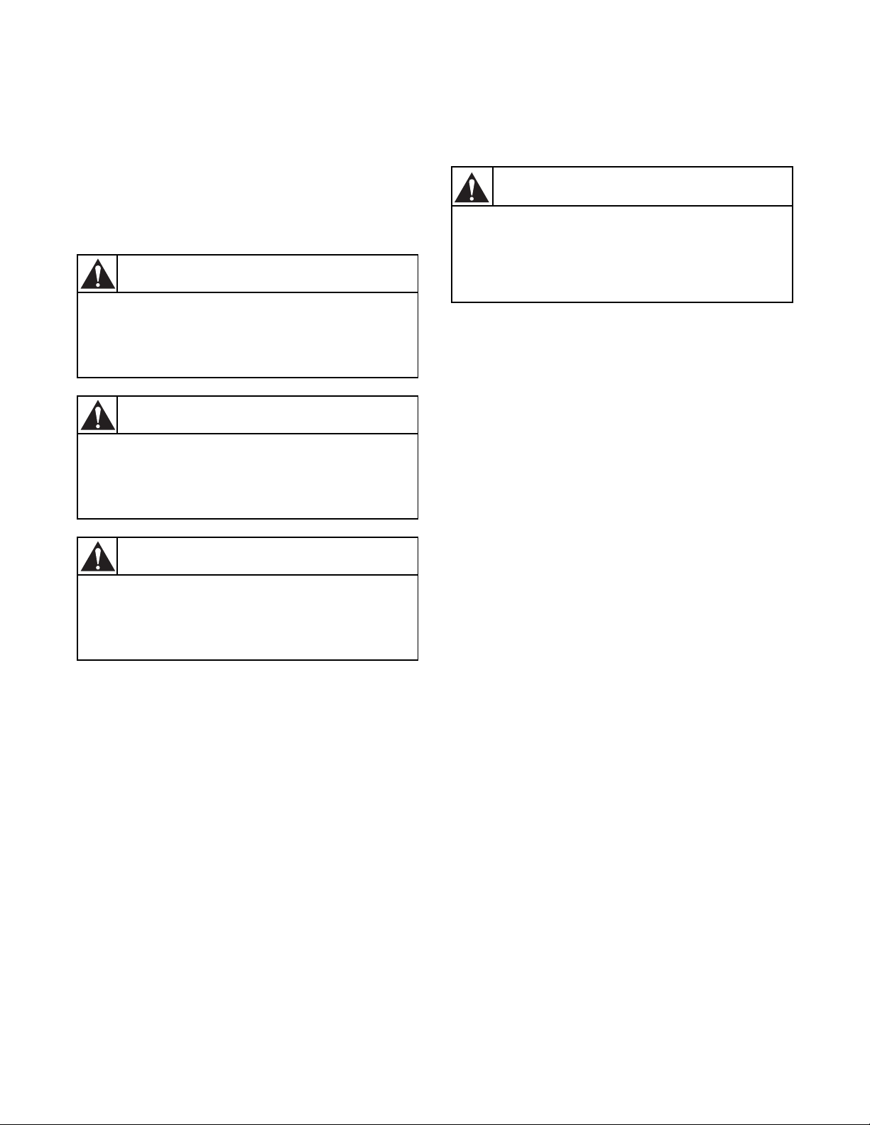
Safety Information
Precautionary statements (“DANGER,” “WARNING,”
and “CAUTION”), followed by specific instructions,
are found in this manual and on machine decals. These
precautions are intended for the personal safety of the
operator, user, servicer, and those maintaining the
machine.
DANGER
DANGER indicates the presence of a
hazard that will cause severe personal
injury, death, or substantial property
damage if the danger is ignored.
WARNING
WARNING indicates the presence of a
hazard that can cause severe personal
injury, death, or substantial property
damage if the warning is ignored.
CAUTION
Important Safety Instructions
WARNING
To reduce the risk of fire, electric shock,
serious injury or death to persons when
using your washer, follow these basic
precautions:
1. Read all instructions before using the washer.
2. Refer to the
Installation Manual for the proper grounding of
the washer.
3. Do not wash textiles that have been previously
cleaned in, washed in, soaked in, or spotted with
gasoline, kerosene, waxes, cooking oils,
dry-cleaning solvents, or other flammable or
explosive substances as they give off vapors that
could ignite or explode.
4. Do not add gasoline, dry-cleaning solvents, or
other flammable or explosive substances to the
wash water. These substances give off vapors that
could ignite or explode.
Grounding Instructions in the
W023
CAUTION indicates the presence of a
hazard that will or can cause minor
personal injury or property damage if the
caution is ignored.
Additional precautionary statements (“IMPORTANT”
and “NOTE”) are followed by specific instructions.
IMPORTANT: The word “IMPORTANT” is used
to inform the reader of specific procedures where
minor machine damage will occur if the procedure
is not followed.
NOTE: The word “NOTE” is used to communicate
installation, operation, maintenance or servicing
information that is important but not hazard
related.
5. Under certain conditions, hydrogen gas may be
produced in a hot water system that has not been
used for two weeks or more. HYDROGEN GAS
IS EXPLOSIVE. If the hot water system has not
been used for such a period, before using a
washing machine or combination washer-dryer,
turn on all hot water faucets and let the water
flow from each for several minutes. This will
release any accumulated hydrogen gas. The gas is
flammable; do not smoke or use an open flame
during this time.
6. Do not allow children to play on or in the washer.
Close supervision of children is necessary when
the washer is used near children. This is a safety
rule for all appliances.
7. Before the washer is removed from service or
discarded, remove the door to the washing
compartment.
8. Do not reach into the washer if the wash drum is
moving.
F232145 (EN)
© Copyright, Alliance Laundry Systems LLC – DO NOT COPY or TRANSMIT
3
Page 6

Installation/Operation Supplement
9. Do not install or store the washer where it will be
exposed to water and/or weather.
10. Do not tamper with the controls.
11. Do not repair or replace any part of the washer,
or attempt any servicing unless specifically
recommended in the user-maintenance instructions
or in published user-repair instructions that the
user understands and has the skills to carry out.
12. To reduce the risk of an electric shock or fire, DO
NOT use an extension cord or an adapter to
connect the washer to the electrical power source.
13. Use washer only for its intended purpose,
washing clothes.
14. ALWAYS disconnect the washer from electrical
supply before attempting any service. Disconnect
the power cord by grasping the plug, not the cord.
15. Install the washer according to the Installation
Instructions. All connections for water, drain,
electrical power and grounding must comply
with local codes and be made by licensed
personnel when required.
16. To reduce the risk of fire, textiles which have
traces of any flammable substances such as
vegetable oil, cooking oil, machine oil,
flammable chemicals, thinner, etc., or anything
containing wax or chemicals such as in mops and
cleaning cloths, must not be put into the washer.
These flammable substances may cause the
fabric to catch on fire by itself.
17. Do not use fabric softeners or products to
eliminate static unless recommended by the
manufacturer of the fabric softener or product.
18. Keep washer in good condition. Bumping or
dropping the washer can damage safety features.
If this occurs, have washer checked by a qualified
service person.
19. Replace worn power cords and/or loose plugs.
20. Be sure water connections have a shut-off valve
and that fill hose connections are tight. CLOSE
the shut-off valves at the end of each wash day.
21. Loading door MUST BE CLOSED any time the
washer is to fill, tumble or spin. DO NOT
bypass the loading door switch by permitting the
washer to operate with the loading door open.
22. Always read and follow manufacturer’s
instructions on packages of laundry and cleaning
aids. Heed all warnings or precautions. To reduce
the risk of poisoning or chemical burns, keep
them out of the reach of children at all times
(preferably in a locked cabinet).
23. Always follow the fabric care instructions
supplied by the textile manufacturer.
24. Never operate the washer with any guards
and/or panels removed.
25. DO NOT operate the washer with missing or
broken parts.
26. DO NOT bypass any safety devices.
27. Failure to install, maintain, and/or operate this
washer according to the manufacturer’s
instructions may result in conditions which can
produce bodily injury and/or property damage.
NOTE: Underloading can cause out-of-balance
conditions that can shorten life of machine.
NOTE: The WARNING and IMPORTANT
SAFETY INSTRUCTIONS appearing in this
manual are not meant to cover all possible
conditions and situations that may occur. Common
sense, caution and care must be exercised when
installing, maintaining or operating the washer.
Any problems or conditions not understood should be
reported to the dealer, distributor, service agent or the
manufacturer.
4
© Copyright, Alliance Laundry Systems LLC – DO NOT COPY or TRANSMIT
F232145 (EN)
Page 7
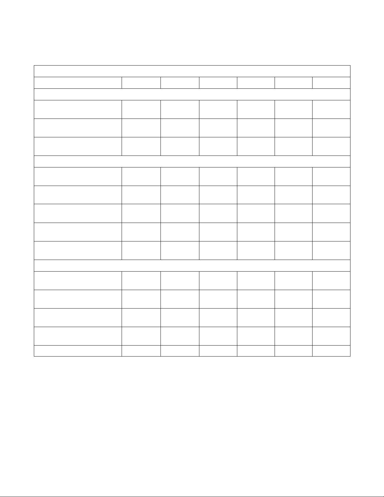
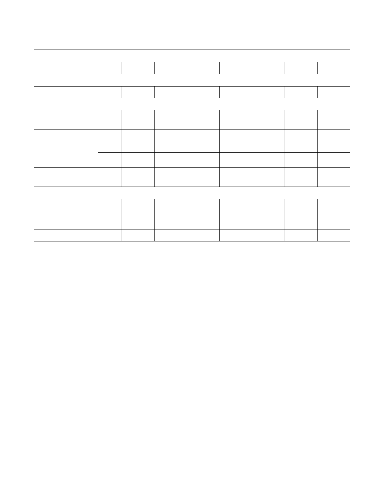
Specifications and Dimensions
Specification 18, 20 25 27, 30 35 40 50
Overall Dimensions
Installation/Operation Supplement
2 Speed Models
Overall width, in. (mm) 26
(660)
Overall height, in. (mm) 42-7/8
(1089)
Overall depth, in. (mm) 29-13/16
(757)
Weight and Shipping Information
Net weight, lbs. (kg) 390
(177)
Domestic shipping weight, lbs.
(kg)
Domestic shipping volume, ft
3
(m
)
Export shipping weight lbs., (kg) 480
Export shipping volume, ft
Wash Cylinder Information
Cylinder diameter,
in. (mm)
3
3
(m3)30.1
428
(194)
28
(0.8)
(218)
(0.86)
21
(533)
26
(660)
45
(1143)
33-7/8
(860)
435
(198)
470
(214)
33
(0.9)
530
(241)
36.7
(1.03)
21
(533)
29
(737)
45-7/8
(1165)
34-13/16
(884)
498
(226)
545
(245)
35
(1.0)
588
(267)
39.6
(1.11)
24
(610)
30-1/8
(765)
47-1/4
(1200)
38-1/2
(978)
650
(295)
680
(309)
39
(1.09)
760
(345)
47.1
(1.32)
26-1/4
(667)
30-5/8
(778)
47-7/8
(1216)
40-3/16
(1021)
706
(321)
744
(338)
42.6
(1.19)
846
(385)
54.1
(1.51)
26-1/4
(667)
34-1/16
(865)
50-13/16
(1291)
41-13/16
(1087)
820
(373)
875
(398)
53
(1.5)
1020
(464)
58.7
(1.67)
30
(762)
Cylinder depth, in. (mm) 13-3/4
(349)
Cylinder volume, ft
Perforation size, in. (mm) 0.188
Perforation open area, % 17 17 23 17 17.5 18
F232145 (EN)
3
(l) 2.76
(78.1)
(4.76)
© Copyright, Alliance Laundry Systems LLC – DO NOT COPY or TRANSMIT
18-3/4
(476)
3.76
(106.5)
0.188
(4.76)
Table 1 (Continued)
(406)
4.19
(118.6)
0.188
(4.76)
16
18-3/8
(467)
5.76
(163.1)
0.188
(4.76)
20-1/4
(514)
6.34
(180)
0.188
(4.76)
20
(508)
8.18
(231.6)
0.188
(4.76)
5
Page 8
Installation/Operation Supplement
T
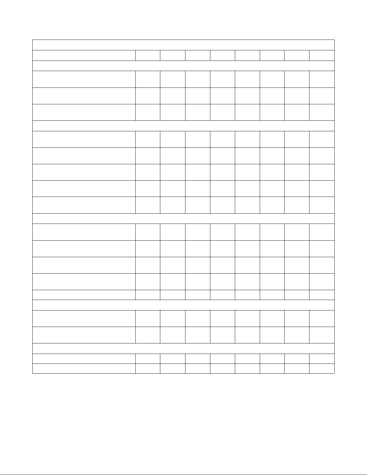
Table 1 (Continued)
2 Speed Models (Continued)
Specification 18, 20 25 27, 30 35 40 50
Door Opening Information
Door opening diameter,
in. (mm)
Height of door bottom above floor,
in. (mm)
12
(305)
14-3/8
(365)
12
(305)
14-3/8
(365)
14-11/32
(364)
14
(356)
14-11/32
(364)
16
(406)
16-1/4
(413)
14-1/2
(368)
16-1/4
(413)
13-1/2
(343)
Power Consumption
Average power used per cycle,
0.20 0.25 0.25 0.30 0.34 0.42
kW-hr
Average HVAC load, Btu/hr 425 400 400 510 510 700
Drive Train Information
Number of motors in drive train 1 1 1 1 1 1
Wash/reverse power, HP (kW) 0.18
(0.13)
High extract power, HP (kW) 1.0
(0.746)
0.25
(0.19)
1.4
(1.04)
0.25
(0.19)
1.4
(1.04)
0.40
(0.30)
1.8
(1.3)
0.40
(0.30)
1.8
(1.3)
0.55
(0.41)
(2.01)
2.7
Cylinder Speeds
Wash/reverse speed, RPM 53 55 47 47 47 44
High extract speed, RPM 525 540 480 470 470 450
Centrifugal Force Data
Wash/reverse centrifugal force, Gs 0.85 0.90 0.75 0.82 0.82 0.825
High extract centrifugal force, Gs 82.1 86.8 78.4 82.3 82.3 86.3
Table 1 (Continued)
6
© Copyright, Alliance Laundry Systems LLC – DO NOT COPY or TRANSMIT
F232145 (EN)
Page 9
Installation/Operation Supplement
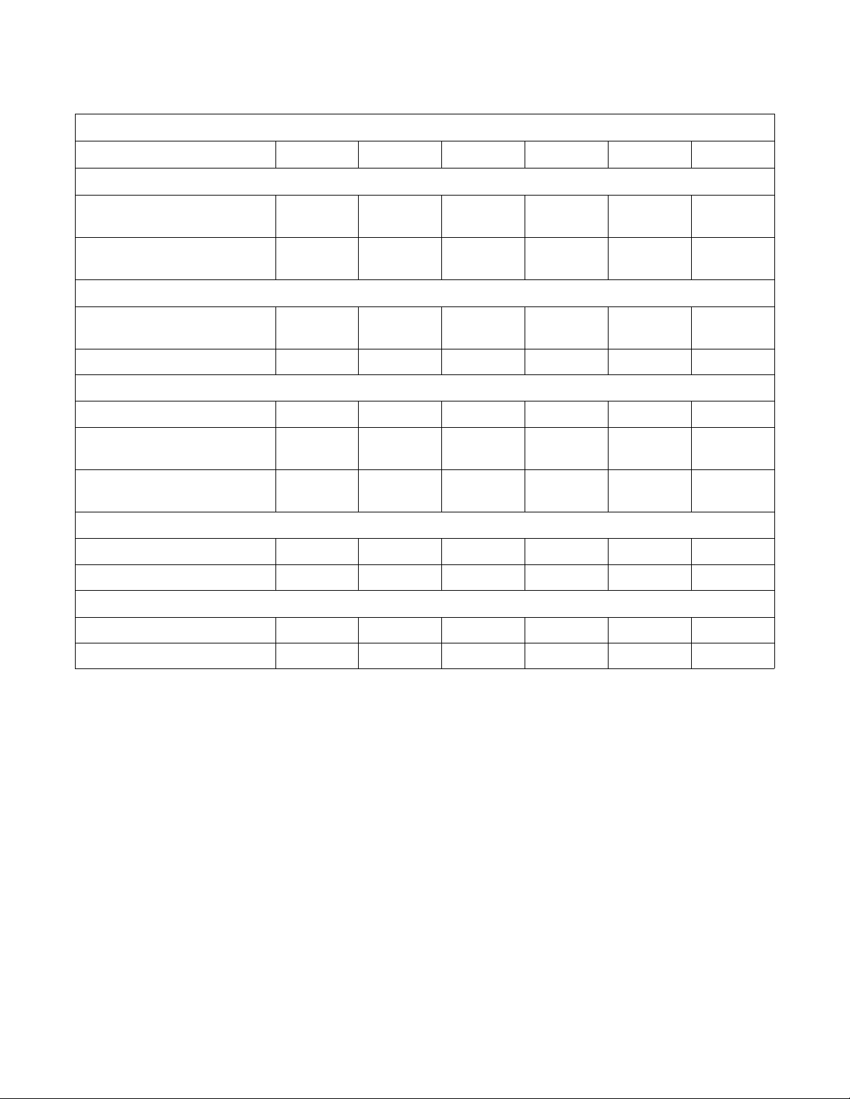
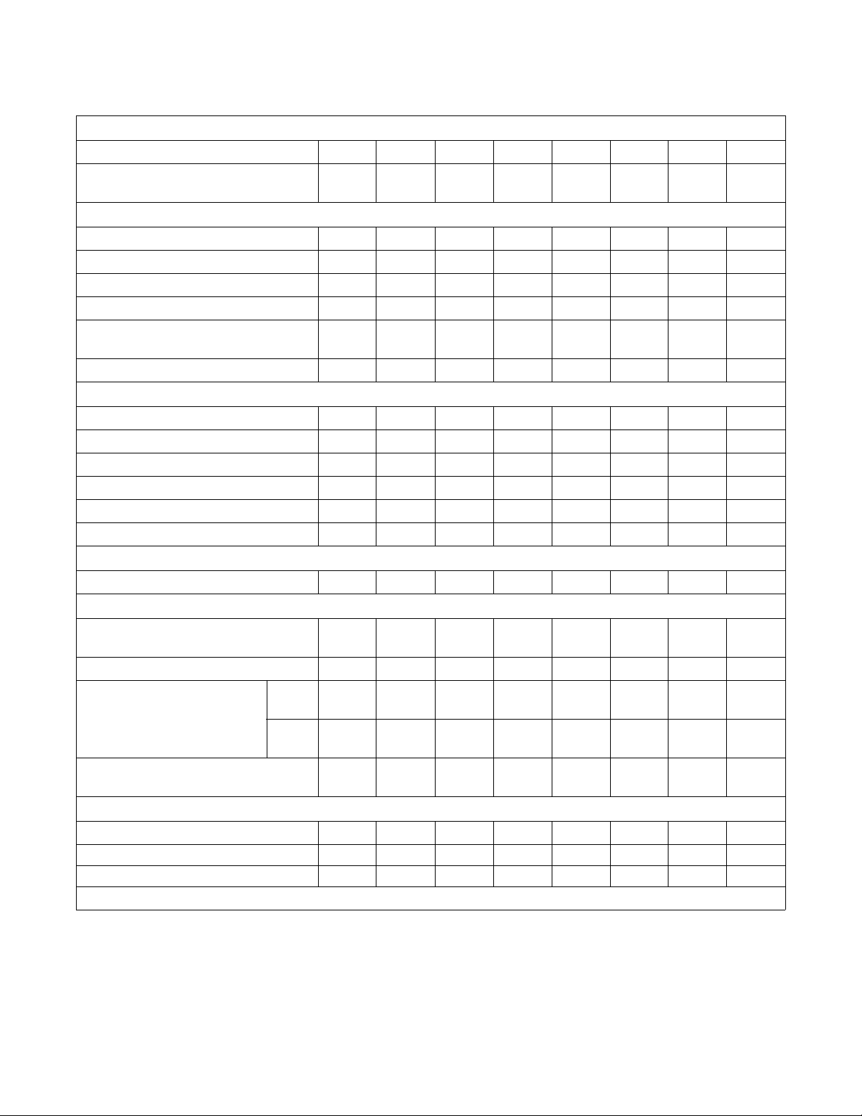
Table 1 (Continued)
2 Speed Models (Continued)
Specification 18, 20 25 27, 30 35 40 50 60
Balance Detection
Vibration switch installed N/A N/A N/A N/A N/A N/A N/A
Direct Steam Heating (Optional)
Steam inlet connection size,
in. (mm)
1/2
(13)
1/2
(13)
1/2
(13)
1/2
(13)
1/2
(13)
1/2
(13)
1/2
(13)
Number of steam inlets 1111111
Steam required to raise
bath water temperature
10°F (6°C)
Average steam use per cycle,
bhp (kg)
LOW 1.05 (0.75) 1.4 (1.01) 1.44 (1.03) 2.06 (1.48) 2.09 (1.51) 2.76 (1.99) 2.76 (1.99)
HIGH 1.4 (1.01) 1.59 (1.15) 1.91 (1.37) 2.69 (1.94) 2.84 (2.04) 3.59 (2.59) 3.59 (2.59)
0.71
(11.1)
0.87
(13.6)
0.97
(15.2)
1.4
(21.6)
1.43
(22.4)
1.84
(28.9)
1.84
(28.9)
Electrical Heating (Optional)
Total electrical heating capacity,
7.8 7.8 7.8 15.6 15.6 23.4 23.4
kW
Electrical heating elements 3336399
Electrical heat element size, kW 2.6 2.6 2.6 2.6 5.2 2.6 2.6
F232145 (EN)
© Copyright, Alliance Laundry Systems LLC – DO NOT COPY or TRANSMIT
7
Page 10

Installation/Operation Supplement
Gap Setting for Vibration Switch
(Variable-Speed and Fixed-Speed
Models)
18, 20 27, 30 35 40 50 60 80 125
Switch gap
setting*
* Gap setting should be made with “GO-NO-GO” type feeler gauge. Lower value must not trip switch. Upper value must trip switch.
After the machine has been properly installed, the
vibration switch gap must be measured before
conducting the Control Function Test. Locate the gap
found between the vibration switch and the machine
structure. Refer to Figures 1, 2, 3, 4 and 5. To check
the gap setting of the switch, proceed as follows:
1. Remove the front panel on 18-50 models.
Remove the rear panel on 60-80 models. Remove
the top cover on the 125 model. The switch can
be seen inside the bottom right corner of the Aframe, mounted on a bracket. Refer to Figures 1,
2, 3, 4 and 5.
0.015-
0.025 in.
(0.38-
0.64 mm)
0.025-
0.035 in.
(0.64-
0.89 mm)
0.030-
0.040 in.
(0.76-
1.02 mm)
0.020-
0.030 in.
(0.51-
0.64 mm)
Tab le 2
0.025-
0.035 in.
(0.64-
0.89 mm)
0.013-
0.015 in.
(0.20-
0.25 mm)
0.009-
0.011 in.
(0.23-
0.28 mm)
0.008 in.
0.20 mm)
0.006-
(0.15-
2. Measure the gap distance when the switch is in
both the open and closed positions. The
specifications should be at the minimum switch
gap setting when the switch is open and at the
maximum switch gap setting when the switch is
closed. If these distances are not correct, adjust
the balance switch to these specifications.
NOTE: The standard position of the switch is open,
or non-tripped.
3. Tighten nuts on switch extension after adjusting
the gap. Measure the gap distance to verify
accurate setting.
8
© Copyright, Alliance Laundry Systems LLC – DO NOT COPY or TRANSMIT
F232145 (EN)
Page 11
Variable-Speed and Fixed-Speed Models
Specification 20 30 35 40 50 60 80 125
Overall Dimensions
Overall width, in. (mm) 26
(660)
Overall height, in. (mm) 42-7/8
(1089)
Overall depth, in. (mm) 29-13/16
(757)
Weight and Shipping Information
Net weight, lbs. (kg) 386
(175)
Domestic shipping weight, lbs. (kg) 424
(191)
3
Domestic shipping volume, ft
(m3)28
(0.8)
Export shipping weight, lbs. (kg) 476
(215)
Export shipping volume, ft
3
(m3)30.1
(0.86)
29
(737)
45-7/8
(1165)
34-13/16
(884)
498
(226)
545
(245)
35
(1.0)
588
(267)
39.6
(1.11)
30-1/8
(765)
47-1/4
(1200)
38-1/2
(978)
621
(282)
670
(301)
39
(1.09)
731
(332)
47.1
(1.32)
30-5/8
(778)
47-7/8
(1216)
40-3/16
(1021)
706
(321)
744
(338)
42.6
(1.19)
846
(385)
54.1
(1.51)
Installation/Operation Supplement
34-1/16
(865)
50-13/16
(1291)
42-13/16
(1087)
767
(348)
818
(371)
53
(1.5)
967
(439)
58.7
(1.67)
34-1/16
(865)
41-1/2
(1054)48(1219)
50-13/16
(1291)56(1422)
42-13/16
(1087)
773
(350)
824
(373)
53
(1.5)
1020
(463)
58.7
(1.67)
51-5/8
(1311)
1406
(633)
1456
(655)
97
(2.7)
1506
(678)
109.5
(3.1)
70-1/2
(1791)
56-3/4
(1441)
2346
(1066)
2421
(1098)
153
(4.3)
2701
(1225)
173
(4.8)
Wash Cylinder Information
Cylinder diameter, in. (mm) 21
(533)
Cylinder depth, in. (mm) 13-3/4
(349)
3
Cylinder volume, ft
(l) 2.76
(78.1)
Perforation size, in. (mm) 0.188
(4.76)
24
(610)
16
(406)
4.19
(118)
0.188
(4.76)
26-1/4
(667)
18-3/8
(467)
5.76
(163.1)
0.188
(4.76)
26-1/4
(667)
20-1/4
(514)
6.34
(180)
0.188
(4.76)
30
(762)
20
(508)
8.18
(232)
0.188
(4.76)
30
(762)
22
(559)
9.00
(255)
0.188
(4.76)
36
(914)
22
(559)
12.96
(367)
0.188
(4.76)
42
(1060)
24
(609)
19.24
(545)
0.188
(4.76)
Perforation open area, % 17231717.518182717
Door Opening Information
Door opening size, in. (mm) 12
(305)
Height of door bottom above floor, in. (mm) 14-3/8
(365)
14-11/32
(364)
14
(356)
14-11/32
(364)
16
(406)
16-1/4
(413)
14-1/2
(368)
16-1/4
(413)
13-1/2
(343)
16-1/4
(413)
13-1/2
(343)
18-1/2
(470)
17-3/4
(451)
20
(508)
29
(737)
Power Consumption
Average power used per cycle, kW-hr 0.05 0.07 0.20 0.34 0.37 0.21 0.40 0.60
Average HVAC load, Btu/hr 400 450 510 510 750 750 950 1200
Table 3 (Continued)
F232145 (EN)
© Copyright, Alliance Laundry Systems LLC – DO NOT COPY or TRANSMIT
9
Page 12
Installation/Operation Supplement
Table 3 (Continued)
Drive Train Information
Number of motors in drive train 11111111
Drive motor power, HP (kW) 2
(1.5)
Cylinder Speeds
Gentle wash/reverse speed, RPM 2927262624242227
Wash/reverse speed, RPM 5248464743434037
Distribution speed, RPM 8286737368776362
Low extract speed, RPM 366 343 328 328 307 307 280 260
Medium extract speed, RPM
(Not available on Electronic Control models.)
High extract speed, RPM 685 641 613 614 573 574 524 485
Centrifugal Force Data
Gentle wash centrifugal force, Gs 0.25 0.25 0.25 0.25 0.25 0.25 0.25 0.43
Wash/reverse centrifugal force, Gs 0.8 0.8 0.8 0.8 0.8 0.8 0.8 0.8
Distribution centrifugal force, Gs 22222222
Low extract centrifugal force, Gs 40 40 40 40 40 40 40 40
Medium extract centrifugal force, Gs 85 85 85 85 85 85 85 85
High extract centrifugal force, Gs 140 140 140 140 140 140 140 140
534 500 478 478 447 447 408 380
2
(1.5)
2
(1.5)
2
(1.5)
2
(1.5)
3
(2.2)
5
(3.7)
7.5
(5.6)
Balance Detection
Vibration switch installed* Standard Standard Standard Standard Standard Standard Standard Standard
Direct Steam Heating (Optional)
Steam inlet connection size,
in. (mm)
Number of steam inlets 11111111
Steam required to raise bath water
temperature 10°F (6°C), lbs. (kg)
Average steam use per cycle, bhp (kg) 0.54
Electrical Heating (Optional)
Total electrical heating capacity, kW 7.8 7.8 15.6
Electrical heating elements 33639912N/A
Electrical heat element size, kW 2.6 2.6 2.6 5.2 2.6 2.6 2.6 N/A
* Refer to Gap Setting for Vibration Switch (Variable-Speed and Fixed-Speed Models) section for specifications.
LOW 0.62
HIGH 0.88
1/2
(13)
(0.28)
(0.4)
(8.3)
1/2
(13)
0.92
(0.42)
1.31
(0.6)
0.73
(11.3)
1/2
(13)
2.1
(1.51)
2.69
(1.96)
1.4
(21.6)
1/2
(13)
2.09
(1.51)
2.84
(2.04)
1.43
(22.4)
15.6
1/2
(13)
2.8
(2.0)
3.6
(2.59)
1.8
(28.9)
23.4 23.4 31.2 N/A
1/2
(13)
3.6
(1.63)
5.5
(2.49)
2.32
(36.4)
1/2
(13)
4.1
(2.93)
6.0
(4.34)
2.93
(45.9)
(19)
(4.9)
(6.4)
(71)
3/4
6.8
8.9
4.5
10
© Copyright, Alliance Laundry Systems LLC – DO NOT COPY or TRANSMIT
F232145 (EN)
Page 13

For 18, 20, 25, 27, 30 and 35 Pound
Capacity Machines
Installation/Operation Supplement
3
2
1 Sump 3 Vibration Switch
2 Gap Distance 4 Switch Extension
1
4
Figure 1
CHM1995N
CHM1995N
F232145 (EN)
© Copyright, Alliance Laundry Systems LLC – DO NOT COPY or TRANSMIT
11
Page 14

Installation/Operation Supplement
For 40 and 50 Pound Capacity Variable-Speed
and Fixed-Speed Machines
3
2
1
3
4
4
1 Sump 3 Vibration Switch
2 Gap Distance 4 Switch Extension
Figure 2
CHM2000N
12
© Copyright, Alliance Laundry Systems LLC – DO NOT COPY or TRANSMIT
F232145 (EN)
Page 15

For 60 Pound Capacity Variable-Speed and
Fixed-Speed Machines
Installation/Operation Supplement
2
3
2
1
6
4
5
1 Lower Bracket 4 Balance Bolt
2 Upper Bracket 5 Lock Nut
3 Vibration Switch 6 Gap Distance
CHM1999N
CHM1999N
F232145 (EN)
Figure 3
© Copyright, Alliance Laundry Systems LLC – DO NOT COPY or TRANSMIT
13
Page 16

Installation/Operation Supplement
For 80 Pound Capacity Machines
1
2
3
1 Switch Extension 3 Vibration Switch
2 Gap Distance
Figure 4
CAB1998N
CHM1998N
14
© Copyright, Alliance Laundry Systems LLC – DO NOT COPY or TRANSMIT
F232145 (EN)
Page 17

For 125 Pound Capacity Machines
3
2
1
1 Vibration Switch 3 Switch Extension
2 Gap Distance
Installation/Operation Supplement
CHM1993N
Figure 5
F232145 (EN)
© Copyright, Alliance Laundry Systems LLC – DO NOT COPY or TRANSMIT
15
Page 18

Installation/Operation Supplement
Dimensional Clearances
F
E
FRONT
A
B
C
D
Figure 6
Machine Capacity Dimensional Clearances
Dimensions 18, 20 25 27, 30 35 40 50 60 80 125
A
B
C
D
E
F
*For 80 pound models intended for standard mounting, clearance should be 6 in. (150 mm).
2 in.
(50 mm)
26 in.
(660 mm)
1 in.
(25 mm)
16-3/8 in.
(416 mm)
25-5/8 in.
(650 mm)
12 in.
(305 mm)
2 in.
(50 mm)
26 in.
(660 mm)
1 in.
(25 mm)
16-3/8 in.
(416 mm)
29-7/16 in.
(705 mm)
12 in.
(305 mm)
2 in.
(50 mm)
29 in.
(737 mm)
1 in.
(25 mm)
19-1/4 in.
(490 mm)
30-1/2 in.
(775 mm)
12 in.
(305 mm)
2 in.
(50 mm)
30-1/8 in.
(765 mm)
1 in.
(25 mm)
19-1/4 in.
(490 mm)
34 in.
(864 mm)
18 in.
(457 mm)
2 in.
(50 mm)
30-5/8 in.
(778 mm)
1 in.
(25 mm)
22 in.
(560 mm)
36 in.
(914 mm)
12 in.
(305 mm)
2 in.
(50 mm)
34-1/16 in.
(865 mm)
1 in.
(25 mm)
22 in.
(560 mm)
37-1/2 in.
(953 mm)
12 in.
(305 mm)
2 in.
(50 mm)
34-1/16 in.
(865 mm)
1 in.
(25 mm)
22 in.
(560 mm)
38-3/4 in.
(984 mm)
12 in.
(305 mm)
2 in.
(50 mm)
41-1/2 in.
(1054 mm)
1 in.*
(25 mm)
25 in.
(635 mm)
51-5/8 in.
(1311 mm)
24 in.
(610 mm)
24 in.
(600 mm)
48 in.
(1219 mm)
12 in.
(300 mm)
26-1/4 in.
(667 mm)
56-3/4 in.
(1441 mm)
24 in.
(610 mm)
U158M
16
Tab le 4
© Copyright, Alliance Laundry Systems LLC – DO NOT COPY or TRANSMIT
F232145 (EN)
Page 19

Dimensions
18, 20, 25, 27, 30, 35, 40, 50, 60 and
80 Models
1
Installation/Operation Supplement
4
3
2
S
R
I
J
5
6
7
8
H
A
B
C
D
1 Supply Dispenser 5 Hot Water Inlet
2 Input Power Block 6 Extra Inlet Valve
3 External Chemical Supply Signal Terminal Strip
(OPL only)
4 Cold Water Inlet 9 Drain Outlet
E
F
G
7 External Chemical Supply Inlet (OPL only)
8 Vacuum Breaker
L
N
Figure 7
K
M
O
9
Q
P
CHM2019N
CHM2019N
F232145 (EN)
© Copyright, Alliance Laundry Systems LLC – DO NOT COPY or TRANSMIT
17
Page 20

Installation/Operation Supplement
Machine Capacity Dimensions
Dimensions 18, 20 25 27, 30 35 40 50 60 80
A
B
C
D
E
F
G
H
K
L
M
N
O
P
Q
R
S
22-15/16 in.
(583 mm)
17-1/4 in.
(438 mm)
14-3/8 in.
(365 mm)
26 in.
(660 mm)
25-5/8 in.
(650 mm)
29-13/16 in.
(757 mm)
0 0 0 1-1/8 in.
42 in.
(1062 mm)
I
J
12-1/2 in.
(318 mm)
11-1/2 in.
(292 mm)
3-1/2 in.
(89 mm)
34-1/2 in.
(876 mm)
5-3/4 in.
(146 mm)
4-1/2 in.
(114 mm)
2 in.
(51 mm)
36-3/16 in.
(919 mm)
38-1/2 in.
(978 m)
1-3/16 in.
(30 mm)
3 in.
(76 mm)
23 in.
(584 mm)
17-1/4 in.
(438 mm)
14-3/8 in.
(365 mm)
26 in.
(660 mm)
30 in.
(762 mm)
34-3/16 in.
(868 mm)
45 in.
(1143 mm)
12-1/2 in.
(318 mm)
11-1/2 in.
(292 mm)
3-1/2 in.
(89 mm)
37-1/2 in.
(952 mm)
5-3/4 in.
(146 mm)
4-1/2 in.
(114 mm)
2 in.
(51 mm)
39-3/16 in.
(995 mm)
41-1/2 in.
(1054 mm)
1-3/16 in.
(30 mm)
3 in.
(76 mm)
24 in.
(610 mm)
17 in.
(432 mm)
14 in.
(356 mm)
29 in.
(737 mm)
30-5/8 in.
(775 mm)
34-13/16 in.
(884 mm)
45 in.
(1143 mm)
15-1/4 in.
(387 mm)
14-3/4 in.
(375 mm)
3-3/4 in.
(95 mm)
37-11/16 in.
(957 mm)
5-7/8 in.
(149 mm)
4 in.
(102 mm)
2 in.
(51 mm)
38-15/16 in.
(989 mm)
41 in.
(1041 mm)
1-3/16 in.
(30 mm)
3 in.
(76 mm)
26 in.
(660 mm)
19 in.
(483 mm)
16 in.
(406 mm)
30-1/8 in.
(765 mm)
34 in.
(864 mm)
38-1/8 in.
(968 mm)
(29 mm)
47 in.
(1194 mm)
14-1/4 in.
(362 mm)
10-13/16 in.
(275 mm)
2-3/4 in.
(70 mm)
40-1/8 in.
(1020 mm)
7-5/16 in.
(186 mm)
4-3/4 in.
(121 mm)
2 in.
(51 mm)
41-15/16 in.
(1064 mm)
41-15/16 in.
(1064 mm)
1-3/16 in.
(30 mm)
3 in.
(76 mm)
25-3/4 in.
(654 mm)
18 in.
(457 mm)
14-1/2 in.
(368 mm)
30-5/8 in.
(778 mm)
36 in.
(914 mm)
40-3/16 in.
(1021 mm)
1/2 in.
(13 mm)
47 in.
(1194 mm)
15-7/16 in.
(392 mm)
14-7/16 in.
(367 mm)
3-13/16 in.
(97 mm)
39 in.
(990 mm)
5-1/2 in.
(140 mm)
4-3/4 in.
(121 mm)
3 in.
(76 mm)
42-1/8 in.
(1070 mm)
43-3/16 in.
(1097 mm)
1-3/16 in.
(30 mm)
3 in.
(76 mm)
26-3/8 in.
(670 mm)
18-1/4 in.
(464 mm)
13-1/2 in.
(343 mm)
34-1/16 in.
(865 mm)
37-3/4 in.
(959 mm)
41-13/16 in.
(1062 mm)
1/2 in.
(13 mm)
49-15/16 in.
(1268 mm)
20-3/4 in.
(527 mm)
19-3/4 in.
(502 mm)
3-1/2 in.
(89 mm)
41-1/2 in.
(1054 mm)
6-7/16 in.
(163 mm)
5 in.
(127 mm)
3 in.
(76 mm)
43-3/16 in.
(1097 mm)
45-1/2 in.
(1156 mm)
1-3/16 in.
(30 mm)
3 in.
(76 mm)
26-3/8 in.
(670 mm)
18-1/4 in.
(464 mm)
15 in.
(381 mm)
34-1/16 in.
(865 mm)
38-3/4 in.
(984 mm)
42-13/16 in.
(1087 mm)
1/2 in.
(13 mm)
49-15/16 in.
(1268 mm)
20-3/4 in.
(527 mm)
19-3/4 in.
(502 mm)
3-1/2 in.
(89 mm)
41-1/2 in.
(1054 mm)
6-7/16 in.
(163 mm)
5 in.
(127 mm)
3 in.
(76 mm)
43-3/8 in.
(1102 mm)
45-1/2 in.
(1156 mm)
1-3/16 in.
(30 mm)
3 in.
(76 mm)
30-5/8 in.
(777 mm)
21-5/8 in.
(549 mm)
17-3/4 in.
(451 mm)
41-1/2 in.
(1054 mm)
48 in.
(1219 mm)
51 in.
(1295 mm)
1/2 in.
(13 mm)
56 in.
(1422 mm)
22-1/4 in.
(572 mm)
14-7/16 in.
(378 mm)
3-7/16 in.
(87 mm)
44-1/2 in.
(1130 mm)
6-3/8 in.
(162 mm)
5-3/4 in.
(146 mm)
(76 mm)
42-3/4 in.
(1086 mm)
50 in.
(1270 mm)
1-3/16 in.
(30 mm)
(76 mm)
3 in.
3 in.
18
Table 5
© Copyright, Alliance Laundry Systems LLC – DO NOT COPY or TRANSMIT
F232145 (EN)
Page 21

125 Model
1
Installation/Operation Supplement
J
K
L
M
N
O
I
2
3
4
5
6
R
S
A
B
C
D
1 Dry Chemical Dispenser (Optional) 5 Liquid Chemical Inlet
2 Cold Water Inlet 6 Steam Inlet (Optional)
3 Extra Water Inlet (Optional) 7 Drain Outlet
4 Hot Water Inlet
E
F
G
P
H
Figure 8
Machine Capacity Dimensions
A
B
C
D
1016 mm (40 in.)
768 mm (30.12 in.)
737 mm (29 in.)
203 mm (8 in.)
K
L
M
N
Q
7
B023I
1041 mm (41 in.)
978 mm (38.5 in.)
851 mm (33.5 in.)
756 mm (29.75 in.)
T
B023I
E
F
G
H
I
J
F232145 (EN)
1219 mm (48 in.)
1283 mm (50.5 in.)
1422 mm (56.75 in.)
25 mm (1 in.)
1791 mm (70.5 in.)
1130 mm (44.5 in.)
O
P
Q
R
S
T
124 mm (4.88 in.)
1622 mm (63.88 in.)
1648 mm (64.88 in.)
1692 mm (66.63 in.)
Tab le 6
© Copyright, Alliance Laundry Systems LLC – DO NOT COPY or TRANSMIT
610 mm (24 in.)
330 mm (13 in.)
19
Page 22

Installation/Operation Supplement
Electrical Specifications
Electrical Specifications
18 and 20 Pound Capacity Models
Code
Voltage Designation Standard Electric Heat
Volt age
Cycle
Phase
Wire
Full Load
Breaker
Amps
Circuit
AWG
mm
2
Full Load
Breaker
Amps
Circuit
AWG
mm
2
2 Speed Models
B 110 – 120 60 1 2 15 20 12 4 N/A
C 380 – 415 50 3 4 4 15 14 2.5 14 15 14 2.5
D 220 – 240 50 3 3 5 15 14 2.5 24 25 10 6
E220 – 2405012102012 4 4245 6 16
F 440 – 480 60 3 3 4 15 14 2.5 16 20 12 4
H 380 60 3 3 4 15 14 2.5 13 15 14 2.5
J 200 50 3 3 5 15 14 2.5 24 25 10 6
O 208 – 240 60 3 3 5 15 14 2.5 24 25 10 6
Y208 – 2406012102012 4 4245 6 16
Variable-Speed Models
Q 200 – 240 50/60 3 3.8 3.8 15 14 2.5 N/A N/A N/A N/A
NOTE: Wire sizes shown are for copper, THHN, 90° conductor per NEC article 310.
Table 7
25, 27 and 30 Pound Capacity Models
Electrical Specifications
Code
Voltage Designation Standard Electric Heat
Volt age
Cycle
Phase
Wire
Full Load
Amps
Breaker
Circuit
Full Load
Breaker
AWG
mm
2
Amps
Circuit
AWG
mm
2
2 Speed Models
C 380 – 415 50 3 4 4 15 14 2.5 15 20 12 4
D 220 – 240 50 3 3 6 15 14 2.5 24 25 10 6
E220 – 2405012102012 4 4245 6 16
F 440 – 480 60 3 3 4 15 14 2.5 16 20 12 4
H 380 60 3 3 4 15 14 2.5 14 15 14 2.5
J 200 50 3 3 6 15 14 2.5 20 25 10 6
O 208 – 240 60 3 3 7 15 14 2.5 25 30 10 6
Y 208 – 240 60 1 2 10 20 12 4 43
45616
Variable-Speed Models
Q 200 – 240 50/60 3 3 4.8 15 14 2.5 N/A N/A N/A N/A
NOTE: Wire sizes shown are for copper, THHN, 90° conductor per NEC article 310.
20
Table 8
© Copyright, Alliance Laundry Systems LLC – DO NOT COPY or TRANSMIT
F232145 (EN)
Page 23

Electrical Specifications
35 Pound Capacity Models
Installation/Operation Supplement
Code
Voltage Designation Standard Electric Heat
Volt age
Cycle
Phase
Wire
Amps
Full Load
Breaker
Circuit
AWG
mm
2
Full Load
Breaker
Amps
Circuit
AWG
2 Speed Models
C 380 – 415 50 3 4 5 15 14 2.5 26 30 10 6
D 220 – 240 50 3 3 7 20 12 4 43 50 6 16
F 440 – 480 60 3 3 5 15 14 2.5 26 30 10 6
O 200 – 240 60 3 3 7 20 12 4 43 50 6 16
Y 208 – 240 60 1 2 12 25 10 6 N/A
Variable-Speed Models
N 440 – 480 50/60 3 3 2.3 15 14 2.5 27.3 30 10 6
P 380 – 415 50/60 3 3 2.3 15 14 2.5 24 25 10 6
Q 208 – 240 50/60 3 3 5.9 15 14 2.5 43.4 45 6 16
T 200 – 240 50/60 1 2 5.9 15 14 2.5 N/A
X 200 – 240 50/60 1 or 3 2 or 3 5.9/5.9 15 14 2x2.5
N/A
3x2.5
NOTE: Wire sizes shown are for copper, THHN, 90° conductor per NEC article 310.
Tab le 9
mm
2
Electrical Specifications
40 Pound Capacity Models
Voltage Designation Standard Electric Heat
Code
Volt age
Cycle
Phase
Wire
Full Load
Breaker
Amps
Circuit
AWG
mm
2
Full Load
Amps
Breaker
Circuit
AWG
2 Speed Models
C 380 – 415 50 3 4 5 15 14 2.5 26 30 10 6
D 220 – 240 50 3 3 7 20 12 4 45 50 6 16
F 440 – 480 60 3 3 5 15 14 2.5 29 30 10 6
H 380 60 3 3 3 15 14 2.5 25 30 10 6
J 200 50 3 3 7 20 12 4 38 40 6 16
O 208 – 240 60 3 3 7 20 12 4 45 50 6 16
Y 208 – 240 60 1 2 13.5 30 10 6 N/A
Variable-Speed Models
N 440 – 480 50/60 3 3 6 15 14 2.5 30 30 10 6
P 380 – 415 50/60 3 3 6 15 14 2.5 29 30 10 6
Q 200 – 240 50/60 3 3 5 15 14 2.5 48 60 6 16
X 200 – 240 50/60 1 or 3 2 or 3 11/11 15 14 2.5 N/A
NOTE: Wire sizes shown are for copper, THHN, 90° conductor per NEC article 310.
mm
2
F232145 (EN)
Tab l e 1 0
© Copyright, Alliance Laundry Systems LLC – DO NOT COPY or TRANSMIT
21
Page 24

Installation/Operation Supplement
Electrical Specifications
50 Pound Capacity Models
Code
Voltage Designation Standard Electric Heat
Volt age
Cycle
Phase
Wire
Full Load
Amps
Breaker
Circuit
Full Load
Breaker
AWG
mm
2
Amps
Circuit
AWG
mm
2
2 Speed Models
C 380 – 415 50 3 4 6 15 14 2.5 39 50 6 16
D220 – 2405033122012 4 6470 4 25
E220 – 2405012153010 6 3740 8 10
F 440 – 480 60 3 3 6 15 14 2.5 39 50 6 16
J 200 50 3 3 10 20 12 3 x 4 N/A
O208 – 2406033102012 4 6470 4 25
Y*208 – 2406012153010 6 3740 8 10
Variable-Speed Models
N 440 – 480 50/60 3 3 4 15 14 2.5 41.6 45 8 10
P 380 – 415 50/60 3 3 4 15 14 2.5 36.5 40 8 10
Q 200 – 240 50/60 3 3 6.3 15 14 2.5 62.6 70 4 25
T 200 – 240 50/60 1 2 6.3 15 14 2.5 N/A
X 200 – 240 50/60 1 or 3 2 or 3 6.3/6.3 15 14 2x2.5
N/A
3x2.5
NOTE: Wire sizes shown are for copper, THHN, 90° conductor per NEC article 310.
*Coin models only.
Tab l e 1 1
22
© Copyright, Alliance Laundry Systems LLC – DO NOT COPY or TRANSMIT
F232145 (EN)
Page 25

Electrical Specifications
60 Pound Capacity Models
Installation/Operation Supplement
Code
Voltage Designation Standard Electric Heat
Volt age
Cycle
Phase
Wire
Full Load
Breaker
Amps
Circuit
AWG
mm
2
Full Load
Breaker
Amps
Circuit
AWG
2 Speed Models
C 380-415 50 3 4 4 15 14 2.5 37 50 8 10.0
D 220-240 50 3 3 7 20 12 4.0 64 70 4 25.0
F 440-480 60 3 3 4 15 14 2.5 41 50 8 10.0
H 380 60 3 3 3 20 12 4.0 33 50 8 10.0
J 200 50 3 3 8 20 12 4.0 55 60 6 16.0
O 208-240 60 3 3 7 20 12 4.0 64 70 4 25.0
X 200-240 50/60 1/3 2/3 9 20 12 4.0 N/A N/A N/A N/A
Variable-Speed Models
N 440-480 50/60 3 3 4 15 14 2.5 42 50 8 10.0
P 380-415 50/60 3 3 5 15 14 2.5 37 40 8 10.0
Q 200-240 50/60 3 3 6 15 14 2.5 65 60 6 16.0
X 200-240 50/60 1/3 2/3 10 20 12 4.0 N/A N/A N/A N/A
NOTE: Wire sizes shown are for copper, THHN, 90° conductor per NEC article 310.
mm
2
Tab l e 1 2
F232145 (EN)
© Copyright, Alliance Laundry Systems LLC – DO NOT COPY or TRANSMIT
23
Page 26

Installation/Operation Supplement
Electrical Specifications
80 Pound Capacity Models
Code
Voltage Designation Standard Electric Heat
Volt age
Cycle
Phase
Wire
Full Load
Amps
Breaker
Circuit
Full Load
Breaker
AWG
mm
2
Amps
Circuit
AWG
Variable-Speed Models
N 440 – 480 50/60 3 3 4.5 15 14 2.5 42 45 8 10
P 380 – 415 50/60 3 3 4.5 15 14 2.5 37 40 8 10
Q 200 – 240 50/60 3 3 12.4 20 12 4 87.4 90 2 35
NOTE: Wire sizes shown are for copper, THHN, 90° conductor per NEC article 310.
Tab l e 1 3
Electrical Specifications
125 Pound Capacity Models
Code
Voltage Designation Standard Electric Heat
Volt age
Cycle
Phase
Wire
Full Load
Amps
Breaker
Circuit
AWG
mm
2
Full Load
Amps
Breaker
Circuit
AWG
Variable-Speed Models
N 440 – 480 50/60 3 3 5.1 15 14 2.5 N/A
P 380 – 415 50/60 3 3 5.1 15 14 2.5 N/A
Q 200 – 240 50/60 3 3 7.9 25 10 6 N/A
NOTE: Wire sizes shown are for copper, THHN, 90° conductor per NEC article 310.
mm
2
mm
2
Tab l e 1 4
24
© Copyright, Alliance Laundry Systems LLC – DO NOT COPY or TRANSMIT
F232145 (EN)
Page 27

Operation
Installation/Operation Supplement
Table 15 (Continued)
Symbol Description
Start
CHM493N
CHM493N
Special Wash
(Owner programming
CHM494N
CHM494N
required – See Cycle Charts
in programming manual)
Normal Cycle
CHM495N
CHM495N
Delicate Cycle
CHM496N
CHM496N
Permanent Press Cycle
CHM497N
CHM497N
Cold Wash
CHM498N
CHM498N
Symbol Description
Edit Down
CHM504N
CHM504N
CHM505N
CHM506N
CHM505N
CHM506N
Start
Select Mode
Wash
CHM507N
CHM507N
Add Bleach
CHM508N
Rinse
CHM509N
CHM509N
CHM499N
CHM499N
CHM500N
CHM500N
CHM501N
CHM502N
CHM503N
Warm Wash
Table 15 (Continued)
Hot Wash
Stop
Start
Edit Up
CHM510N
CHM510N
CHM511N
CHM512N
CHM2003N
CHM2003N
CHM2004N
CHM2004N
Table 15 (Continued)
Spin
Door Open
Clean Filter
Reduced Spin
(∨) keypad
Extra Wash
(∧) keypad
F232145 (EN)
© Copyright, Alliance Laundry Systems LLC – DO NOT COPY or TRANSMIT
25
Page 28

Installation/Operation Supplement
Table 15 (Continued)
Symbol Description
95C
95C
60C
60C
40C
40C
*
<
CHM1980N
CHM1980N
CHM1981N
CHM1981N
CHM1982N
CHM1982N
CHM1983N
CHM1983N
CHM1984N
CHM1984N
CHM1985N
CHM1985N
CHM1986N
CHM1986N
Normal Wash
Hot
Permanent Press
Hot
Normal Wash
Warm
Permanent Press
Warm
Normal Wash
Cold
Permanent Press/Exit
Cold
Hand Wash/Edit Up
30C
<
CHM1987N
CHM1987N
CHM1988N
CHM1988N
CHM1989N
CHM1989N
CHM1990N
CHM1990N
Gentle Wash/Edit Down
Cold
Time
Start/Enter/
Wash Temperature Display
Vend Price/Actuation
26
© Copyright, Alliance Laundry Systems LLC – DO NOT COPY or TRANSMIT
F232145 (EN)
Page 29

Installation/Operation Supplement
Instructions for EDC Control
1. Turn on the main power source (circuit breaker).
2. Push button and turn handle clockwise to open.
Refer to Figure 9.
U001IE1B
U001IE1B
Figure 9
3. Load to capacity whenever possible. DO NOT
OVERLOAD. Refer to Figure 10.
4. Close door and turn handle counterclockwise
until button pops out. Refer to Figure 11.
U005IE1B
U005IE1B
Figure 11
5. Select cycle and temperature. Refer to Figure 12.
6. For machines equipped with a coin meter: Insert
coins. Refer to Figure 12.
Figure 10
U003IE1A
WASH
RINSE
INSERT
COIN/CARD
CLOSE
DOOR
ADD
SPIN
BLEACH
NORMAL
HOT
PERM
PRESS
WARM
DELICATE
COLD
SPECIAL
WASH
B148R
Figure 12
F232145 (EN)
© Copyright, Alliance Laundry Systems LLC – DO NOT COPY or TRANSMIT
27
Page 30

Installation/Operation Supplement
7. For machines equipped with a cardreader:
Insert card into cardreader and follow the
instructions. Refer to Figure 13. DO NOT
REMOVE CARD UNTIL DISPLAY ON
CARDREADER READS “Remove Card”.
INSERT
WASH
COIN/CARD
CLOSE
RINSE
DOOR
ADD
SPIN
BLEACH
NORMAL
HOT
PERM
PRESS
WARM
DELICATE
DELICATES
COLD
COLD
*
START
SPECIAL
WASH
B149R
Figure 13
8. Add detergent to container 1 and softener to
container 3. Press the START key. Refer to
Figure 14.
B149R
NOTE: If a higher-priced cycle is selected, after the
full price has been satisfied for current cycle,
display will show additional price required and the
INSERT COIN/CARD light will flash. Insert coins/
card to satisfy price for special cycle. If price is not
satisfied, the previous cycle selected will begin after
one minute.
9. If display flashes “SPEC” then “CYCL”, extra
options such as high-speed extract or extra rinse
are available. If desired, insert coins/card to meet
additional price shown on display. If not desired,
wait 30 seconds for earlier cycle selection to
continue.
10. Add bleach to container 2 when ADD BLEACH
light is lit. Refer to Figure 15.
1
2
3
L
IA
C
E
P
H
S
S
A
W
*
T
R
S
A
E
T
T
A
S
C
I
L
E
D
M
R
E
S
P
S
COLD
E
R
P
M
L
R
A
M
R
WA
O
N
D
T
R
R
A
E
S
C
/
N
I
N
I
O
C
OT
H
E
S
O
L
R
C
O
H
O
S
D
A
W
H
D
C
D
A
A
E
E
L
S
B
N
I
R
N
I
P
S
1
SPECIAL
WASH
*
START
1 Detergent
2 Bleach
3 Softener
T
R
R
A
E
S
C
/
N
I
N
I
O
C
E
S
O
L
R
C
O
H
O
S
D
A
W
H
D
C
D
A
A
E
E
L
S
B
N
I
R
N
I
P
S
2
Figure 14
3
WASH
RINSE
SPIN
L
A
I
C
E
P
H
S
S
A
W
*
S
E
T
A
START
C
I
L
E
D
M
D
R
L
E
S
O
P
S
C
E
R
P
M
L
R
A
M
R
WA
O
N
D
T
O
H
1 Detergent
INSERT
COIN/CARD
CLOSE
DOOR
ADD
BLEACH
B156R
2 Bleach
B155R
3 Softener
Figure 15
B155R
11. Cycle is complete when display reads “:00”.
28
© Copyright, Alliance Laundry Systems LLC – DO NOT COPY or TRANSMIT
F232145 (EN)
Page 31

Installation/Operation Supplement
Instructions for Mechanical Timer
1. Turn on the main power source (circuit breaker).
For non-coin models: Turn on the On/Off switch
on the front panel to the On position.
2. Push button and turn handle clockwise to open.
Refer to Figure 16.
Figure 16
For non-coin models: Press and hold the DOOR
UNLOCK button on the left side of the control
panel while performing the above step. Refer to
Figure 17.
U001IE1B
U001IE1B
3. Load to capacity whenever possible. DO NOT
OVERLOAD. Refer to Figure 18.
U003IE1A
Figure 18
4. Close door and turn handle counterclockwise
until button pops out. Refer to Figure 19.
On
U005IE1B
Figure 19
DOOR UNLOCK
Off
U135R
U135R
Figure 17
F232145 (EN)
© Copyright, Alliance Laundry Systems LLC – DO NOT COPY or TRANSMIT
29
Page 32

Installation/Operation Supplement
5. Select wash cycle. Refer to Figure 20.
CYCLE INDICATOR WASH CYCLES
P
R
E
W
N
A
I
S
H
HOT WARM WARM COLD
H
HEAVILY
PERM-
NORMAL
S
A
SOILED
W
PRESS
WASH
DELICATE
KNITS
ON
ADD BLEACH
WHEN LIT
P
S
R
I
N
S
E
Figure 20
6. At start of cycle, add liquid and/or powder
supplies to supply dispenser. Refer to Figure 21.
a. Add detergent to container 1.
b. Add softener to container 3.
For non-coin models: Liquid supplies may be
injected directly into the supply dispenser by an
external chemical supply dispenser. Refer to
Installation and Programming Manuals.
U002IE1A
For non-coin models: Press the Start button.
Refer to Figure 22.
DELICATE
KNITS
WARM COLD
Figure 22
On Start
Off
U136R
U136R
8. Add bleach to container 2 when ADD BLEACH
light is lit. Refer to Figure 23.
3
1
7. For coin models: Insert required number of coins
to start machine. Refer to Figure 21.
3
2
1
B157R
1 Detergent
2 Bleach
3 Softener
Figure 21
ON
ADD BLEACH
WHEN LIT
1 Detergent
2 Bleach
3 Softener
2
B158R
B159R
Figure 23
30
© Copyright, Alliance Laundry Systems LLC – DO NOT COPY or TRANSMIT
F232145 (EN)
Page 33

Installation/Operation Supplement
Instructions for S, P and V Series
Microcomputers
1. Turn on main power source (circuit breaker).
For non-coin models: Turn the On/Off switch on
the front panel to the On position.
2. Push button and turn handle clockwise to open.
Refer to Figure 24.
U001IE1B
U001IE1B
Figure 24
3. Load to capacity whenever possible. DO NOT
OVERLOAD. Refer to Figure 26.
U003IE1A
Figure 26
4. Close door and turn handle counterclockwise
until button pops out. Refer to Figure 27.
For non-coin models: Press and hold the DOOR
UNLOCK button on the left side of the control
panel while performing the above step. Refer to
Figure 25.
On
DOOR UNLOCK
Off
U135R
U135R
Figure 25
U005IE1B
Figure 27
F232145 (EN)
© Copyright, Alliance Laundry Systems LLC – DO NOT COPY or TRANSMIT
31
Page 34

Installation/Operation Supplement
5. Add liquid and/or powder supplies to supply
dispenser. Refer to Figure 28.
a. Add detergent to container 1.
b. Add softener to container 3.
For non-coin models: Liquid supplies may be
injected directly into the supply dispenser by an
external chemical supply dispenser. Refer to
Installation and Programming Manuals.
6. Press the Up and Down keys to select wash cycle.
Refer to Figure 29.
7. For coin models: Insert required number of coins
to start machine. Refer to Figure 28.
3
2
1
B157R
1 Detergent
2 Bleach
3 Softener
9. When applicable, add beach to container 2 when
the display reads “bLCH”. Refer to Figure 30.
2
1
1 Up
2 Down
3 Start
4 Stop
CYCLE SELECTION
Figure 30
3
4
B160R
NOTE: To stop a cycle at any time, press the Stop
key. Non-coin models only.
NOTE: To display the temperature of the water
while a cycle is running, press the Up key. To
display the number of the cycle in progress, press
the Start key.
Figure 28
8. For non-coin models: Press the Start key. Refer
to Figure 29.
2
1
CYCLE SELECTION
1 Up
2 Down
3 Start
4 Stop
Figure 29
3
4
B159R
32
© Copyright, Alliance Laundry Systems LLC – DO NOT COPY or TRANSMIT
F232145 (EN)
Page 35

Installation/Operation Supplement
Instructions for B Series
Microcomputer
NOTE: Opening the coin box while in Run Mode
and before a cycle has started will put control into
Audit Mode. Display will show “Audt”. To revert
back to Run Mode, close coin box and press START
keypad.
1. Turn on main power source (circuit breaker).
2. Push button and turn handle clockwise to open.
Refer to Figure 31.
4. Close door and turn handle counterclockwise
until button pops out. Refer to Figure 33.
U005I
Figure 33
5. The default wash cycle will display. Refer to
Figure 34.
NOTE: Perm Press Cold is the default cycle for
coin models if none is selected. Perm Press Hot is
the default cycle for OPL models.
U001I
Figure 31
3. Load to capacity whenever possible. DO NOT
OVERLOAD. Refer to Figure 32.
U003I
Figure 32
WASH
ADD
BLEACH
RINSE
SPIN
DOOR
CLEAN
FILTER
START
Figure 34
NORMAL
HOT
LIGHT SOIL
HOT
HEAVY SOIL
HOT HOT
STAINED
HOT
95C 95C
60C 60C
40C 40C
<
PERM PRESS
HOT
TM
VISA
WARM
UNIFORMS
DELICATE
COLD
30C
CHM522N
CHM522N
<
CHM1764C
F232145 (EN)
© Copyright, Alliance Laundry Systems LLC – DO NOT COPY or TRANSMIT
33
Page 36

Installation/Operation Supplement
6. If desired, select a different cycle at this point or
after satisfying vend. The LED indicator for that
cycle will light.
7. Add liquid and/or powder supplies to supply
dispenser. Refer to Figure 35.
a. Add detergent to compartment 1.
b. Add softener to compartment 3.
3
2
1
B157R
1 Detergent
2 Bleach
3 Softener
9. If the machine is a card operated unit, insert and
remove card. Contact the card reader
manufacturer for details.
10. If the unit is interfaced to a central/remote pay
system, go to the central/remote pay console,
make payment and select the machine. Contact
the pay system manufacturer for more details.
11. When applicable, add bleach to compartment 2
when the ADD BLEACH LED is lit.
12. Press the desired wash cycle key.
13. Press the START keypad.
14. During first fill, the desired wash cycle can be
changed. After first fill has ended, the wash cycle
active at that moment remains the chosen wash
cycle.
15. When cycle is complete, display shows “donE”.
Figure 35
8. If the machine is a coin operated unit, add coins.
As each coin is added, the display counts down to
the amount remaining.
34
© Copyright, Alliance Laundry Systems LLC – DO NOT COPY or TRANSMIT
F232145 (EN)
Page 37

Installation/Operation Supplement
Instructions for A Series
Microcomputer
NOTE: Opening the coin box while in Run Mode
and before a cycle has started will put control into
Audit Mode. Display will show “Audt”. To revert
back to Run Mode, close coin box and press START
keypad.
1. Turn on main power source (circuit breaker).
2. Push button and turn handle clockwise to open.
Refer to Figure 36.
4. Close door and turn handle counterclockwise
until button pops out. Refer to Figure 38.
U005I
Figure 38
5. The default wash cycle will display. Refer to
Figure 39.
NOTE: The default cycle is Perm Press 60°C for
coin models if no cycle is selected.
U001I
Figure 36
3. Load to capacity whenever possible. DO NOT
OVERLOAD. Refer to Figure 37.
U003I
Figure 37
CHM1759C
Figure 39
F232145 (EN)
© Copyright, Alliance Laundry Systems LLC – DO NOT COPY or TRANSMIT
35
Page 38

Installation/Operation Supplement
6. If desired, select a different cycle at this point or
after satisfying vend. The LED indicator for that
cycle will light.
7. Add liquid and/or powder supplies to supply
dispenser. Refer to Figure 40.
a. Add detergent to compartment 1.
b. Add softener to compartment 3.
.
3
2
1
1 Detergent
2 Bleach
3 Softener
B157R
10. If the unit is interfaced to a central/remote pay
system, go to the central/remote pay console,
make payment, select the machine, and follow
central/remote pay system instructions.
11. Press the desired wash cycle key if it hasn’t
already been selected.
NOTE: Once START keypad is pressed, the
selected wash cycle is locked in and wash cycle will
begin.
12. Press the START keypad.
13. Add bleach if and when prompted (display will
show “bLCH”, signal will sound on and off for
45 seconds and Add Bleach indicator lights).
NOTE: If the version of the control in machine is
capable of reading temperature and control is not
in Audit Mode, pressing the START keypad while a
cycle is running will cause display to show
temperature. Press START keypad again to revert
to minutes remaining shown in display.
14. When cycle is complete, display shows “dOnE”,
the Door Open LED lights and door can be
opened.
Figure 40
8. If the machine is a coin operated unit, add coins.
As each coin is added, the display counts down to
the amount remaining.
9. If the machine is a card operated unit, insert and
remove card per card system instructions.
36
© Copyright, Alliance Laundry Systems LLC – DO NOT COPY or TRANSMIT
F232145 (EN)
 Loading...