

Alliance Laundry Systems CT035L, CT035N, CHD35G2, CU035L, CU035N Troubleshooting Manual
...Page 1
Tumble Dryers
S
TART
2
5
C
H
I
G
H
T
E
M
P
M
E
D
T
E
M
P
L
O
W
T
E
M
P
N
O
H
E
A
T
1
2
3
S
E
L
E
C
T
T
E
M
P
I
N
S
E
R
T
C
O
I
N
P
U
S
H
S
T
A
R
T
25 Pound Capacity
30 Pound Capacity
35 Pound Capacity
55 Pound Capacity
Starting Serial No. 0602004144
Refer to Page 7 for Model Numbers
Troubleshooting
www.alliancelaundry.com
T463PE1A
Part No. 70380601R4
January 2013
Page 2

Page 3

Table of
Contents
Section 1 – Safety Information .......................................................... 5
Locating an Authorized Service Person ............................................... 7
Safety Warnings and Decals................................................................. 7
Safety Precautions for Servicing Tumble Dryers ................................. 7
Section 2 – Introduction ..................................................................... 9
Model Identification ............................................................................. 9
Serial Plate Location............................................................................. 12
Customer Service.................................................................................. 12
Wiring Diagram.................................................................................... 12
How a Tumble Dryer Works ................................................................ 13
Theory of Operation ............................................................................. 14
Section 3 – Machine Troubleshooting............................................... 17
1. Tumble Dryer Does Not Start .................................................. 18
2. Motor Does Not Start............................................................... 19
3. Motor Overload Protector Cycles Repeatedly ......................... 20
4. Motor Runs But Cylinder Does Not Turn................................ 21
5. Motor Does Not Stop ............................................................... 22
6. No Heat Condition (Non-CE and Non-Australian Models)..... 23
7. Burner Does Not Ignite............................................................ 25
8. Burner Ignites and Goes Out Repeatedly................................. 28
9. Burner Does Not Shut Off ....................................................... 29
10. Clothes Do Not Dry ................................................................. 30
11. Tumble Dryer Overheating ...................................................... 32
12. Burner Not Burning Properly................................................... 33
13. Loading Door Opens During Operation................................... 34
14. Cylinder Continues to Spin with Door Open........................... 35
15. Coin Does Not Fall into Coin Vault or Coin Drop Sensor
Does Not Register that Coin Has Been Entered ...................... 36
16. Cylinder Is “Stained” ............................................................... 39
Section 4 – Fire Supression System Troubleshooting...................... 40
17. Tumble Dryer Does Not Operate and Light Is On................... 41
18. Water Discharge, but No Fire .................................................. 42
19. Tumble Dryer Does Not Operate and Light Is Off .................. 43
20. Tumble Dryer Operates, but Water Does Not Discharge
and Light Is On ........................................................................ 44
Section 5 – Adjustments ..................................................................... 46
21. Loading Door Switch............................................................... 46
22. Loading Door Strike................................................................. 46
23. Aligning Door Strike................................................................ 47
24. Cleaning Coin Drop ................................................................. 47
Section 6 – Micro Display Control (MDC) Troubleshooting.......... 50
Models with BC, BL, BX and BY Control Suffixes
25. Coins Ignored When Entered................................................... 50
26. Control Has No Display........................................................... 51
© Copyright 2013, Alliance Laundry Systems LLC
All rights reserved. No part of the contents of this book may be reproduced or transmitted in any form or by any
means without the expressed written consent of the publisher.
70380601 1
© Copyright, Alliance Laundry Systems LLC – DO NOT COPY or TRANSMIT
Page 4

27. Door Open Indicator ................................................................ 53
28. Motor Will Not Start/Run ........................................................ 55
29. Unit Will Not Heat – Gas......................................................... 59
30. Unit Will Not Heat – Steam..................................................... 62
31. Unit Will Not Heat – Electric .................................................. 65
32. Error Codes .............................................................................. 68
Gas and Steam Models
Control Circuit Schematic.................................................................69
Control Circuit Connection...............................................................70
Gas and Steam Models
Control Box Schematic .....................................................................71
Control Box Connection ...................................................................72
Gas and Steam Models
Control Circuit Schematic.................................................................73
Gas and Steam Models
Control Circuit Schematic.................................................................74
Gas and Steam Models
Control Box Schematic .....................................................................75
Control Box Connection ...................................................................76
Electric Models
Control Circuit Schematic.................................................................77
Control Circuit Connection...............................................................78
Electric Models
Control Box Connection ...................................................................79
Control Box Schematic .....................................................................80
Section 7 – On Premise Micro Control Troubleshooting................ 81
Models with OM Control Suffix
33. Control Has No Display........................................................... 82
34. Door Open Indicator ................................................................ 84
35. Motor Will Not Start/Run ........................................................ 87
36. Unit Will Not Heat – Gas......................................................... 90
37. Unit Will Not Heat – Steam..................................................... 93
38. Unit Will Not Heat – Electric .................................................. 96
39. Error Codes .............................................................................. 99
Section 8 – NetMaster Troubleshooting ........................................... 100
Models with NC, NR, NX, NY, ZC, ZR, ZX and ZY
Control Suffixes
40. No Infra-red (IR) Communication ........................................... 100
41. Coins Ignored When Entered................................................... 101
42. Control Has No Display........................................................... 102
43. Door Open Indicator ................................................................ 104
44. Motor Will Not Start/Run ........................................................ 106
45. Unit Will Not Heat – Gas......................................................... 110
46. Unit Will Not Heat – Steam..................................................... 113
Section 9 – Hybrid Timer Control Troubleshooting ....................... 115
Models with QT, SD and SX Control Suffixes
47. Coins Ignored When Entered................................................... 115
2 70380601
© Copyright, Alliance Laundry Systems LLC – DO NOT COPY or TRANSMIT
Page 5

48. Control Has No Display – OPL Models .................................. 116
49. Display Flashes “dr” With Door Closed – OPL Models ......... 119
50. Vend Satisfied, No In Use LED – Coin Models...................... 122
51. In Use LED Lit, No Motor Run – Coin Models ...................... 126
52. Motor Will Not Start/Run – Coin Models ............................... 129
53. Motor Will Not Start/Run – OPL Models................................ 132
54. Unit Will Not Heat – Gas – Coin Models................................ 135
55. Unit Will Not Heat – Gas – OPL Models ................................ 138
56. Unit Will Not Heat – Electric OPL.......................................... 141
57. Error Codes .............................................................................. 145
Section 10 – Electronic Control Troubleshooting............................ 146
Models with KB, KC, KX, KV, KW, KY, LC, LX, LY, WC,
WX and WY Control Suffixes
58. No Infrared Communication .................................................... 147
59. Coins Ignored When Entered................................................... 148
60. No Display ............................................................................... 149
61. “Door Open” Indicator............................................................. 151
62. No Start/Run ............................................................................ 153
63. Unit Will Not Heat – Gas......................................................... 155
64. Unit Will Not Heat – Steam..................................................... 158
65. Unit Will Not Heat – Electric .................................................. 160
66. CE Models No Display ............................................................ 163
67. CE Models “Door Open” Indicator.......................................... 165
68. CE Models No Start/Run ......................................................... 167
69. CE Models Will Not Heat – Gas/Steam................................... 169
70. CE Models Will Not Heat – Electric ....................................... 172
Section 11 – LED OPL and UniLinc Troubleshooting.................... 175
Models with EO, RE, RU and UO Control Suffixes
71. No Fan Motor Rotation ............................................................ 176
72. No Drive Motor Rotation......................................................... 179
73. Stove and Cabinet Limit Errors ............................................... 182
74. No Display ............................................................................... 184
75. Airflow Errors .......................................................................... 186
76. Fan Motor Centrifugal Switch Error........................................ 188
77. Close Door Indication .............................................................. 190
78. Moisture Sensor Error.............................................................. 192
Troubleshooting the Moisture Sensor Circuit....................................... 194
79. Troubleshooting at the Control ................................................ 194
80. Troubleshooting From Control to Slip Ring Assembly........... 196
81. Troubleshooting At Slip Ring Assembly................................. 198
82. Troubleshooting From Slip Ring Assembly to Moisture
Sensing Baffle and Basket ....................................................... 198
83. Troubleshooting from Basket Shaft to Moisture Sensing
Baffle with Machine Basket Removed .................................... 198
84. Troubleshooting at the Moisture Sensing Baffles with
Machine Basket Removed ....................................................... 199
85. Fan Motor Contactor Error ...................................................... 200
70380601 3
© Copyright, Alliance Laundry Systems LLC – DO NOT COPY or TRANSMIT
Page 6

86. Rotation Sensor Error............................................................... 202
87. Shorted or Open Thermistor .................................................... 204
88. Fuses and Transformer Configuration Jumper......................... 206
89. Dip Switch/Harness Index Mismatch ...................................... 207
90. Electronic Control Testing....................................................... 208
91. Diagnostic Testing ................................................................... 216
4 70380601
© Copyright, Alliance Laundry Systems LLC – DO NOT COPY or TRANSMIT
Page 7
Section 1
Danger indicates an imminently hazardous
situation that, if not avoided, will cause
severe personal injury or death.
DANGER
Warning indicates a hazardous situation
that, if not avoided, could cause severe
personal injury or death.
WARNING
Caution indicates a hazardous situation
that, if not avoided, may cause minor or
moderate personal injury or property
damage.
CAUTION
•Failure to install, maintain and/or operate
this product according to the
manufacturer’s instructions may result in
conditions which can produce serious
injury, death and/or property damage.
•Do not repair or replace any part of the
product or attempt any servicing unless
specifically recommended or published
in this Service Manual and unless you
understand and have the skills to carry
out the servicing.
•Whenever ground wires are removed
during servicing, these ground wires
must be reconnected to ensure that the
product is properly grounded and to
reduce the risk of fire, electric shock,
serious injury or death.
W006R2
WARNING
Safety Information
Throughout this manual and on machine decals, you
will find precautionary statements (“CAUTION”,
“WARNING”, and “DANGER”) followed by specific
instructions. These precautions are intended for the
personal safety of the operator, user, servicer, and those
maintaining the machine.
Additional precautionary statements (“IMPORTANT”
and “NOTE”) are followed by specific instructions.
IMPORTANT: The word “IMPORTANT” is used
to inform the reader of specific procedures where
minor machine damage will occur if the procedure
is not followed.
NOTE: The word “NOTE” is used to communicate
installation, operation, maintenance or servicing
information that is important but not hazard
related.
In the interest of safety, some general precautions
relating to the operation of this machine follow.
70380601 5
© Copyright, Alliance Laundry Systems LLC – DO NOT COPY or TRANSMIT
Page 8
Safety Information
To re d uc e th e r is k o f e l ec tri c s h oc k, fir e,
explosion, serious injury or death:
•Disconnect electric power to the tumble
dryer before servicing.
•Never start the tumble dryer with any
guards/panels removed.
•Whenever ground wires are removed
during servicing, these ground wires
must be reconnected to ensure that the
tumble dryer is properly grounded.
W240R1
WARNING
Repairs that are made to your products by
unqualified persons can result in hazards
due to improper assembly or adjustments
subjecting you, or the inexperienced
person making such repairs, to the risk of
serious injury, electrical shock, or death.
W007
WARNING
If you or an unqualified person perform
service on your product, you must assume
the responsibility for any personal injury or
property damage which may result. The
manufacturer will not be responsible for
any injury or property damage arising from
improper service and/or service
procedures.
W008
CAUTION
IMPORTANT INFORMATION: During the
lifetime of a tumble dryer, it may require service.
The information contained in this manual was
written and is intended for use by qualified service
technicians who are familiar with the safety
procedures required in the repair of a tumble dryer,
and who are equipped with the proper tools and
testing equipment.
NOTE: The WARNING and IMPORTANT
instructions appearing in this manual are not meant
to cover all possible conditions and situations that
may occur. It must be understood that common
sense, caution and carefulness are factors which
CANNOT be built into this tumble dryer. These
factors MUST BE supplied by the person(s)
installing, maintaining or operating the tumble
dryer.
Always contact your dealer, distributor, service agent
or the manufacturer on any problems or conditions you
do not understand.
6 70380601
© Copyright, Alliance Laundry Systems LLC – DO NOT COPY or TRANSMIT
Page 9

Safety Information
Locating an Authorized Service
Person
Alliance Laundry Systems is not responsible for
personal injury or property damage resulting from
improper service. Review all service information
before beginning repairs.
Warranty service must be performed by an
authorized technician, using authorized factory
parts. If service is required after the warranty
expires, Alliance Laundry Systems also
recommends contacting an authorized technician
and using authorized factory parts.
Safety Warnings and Decals
SAFETY WARNINGS and decals have been provided
in key locations to remind you of important precautions
for the safe operation and maintenance of your tumble
dryer. Please take the time to review these warnings
before proceeding with service work.
All decals have been designed and applied to withstand
washing and cleaning. Decals should be checked
periodically to be sure they have not been damaged,
removed, or painted.
Safety Precautions for Servicing
Tumble D rye rs
Prior to servicing tumble dryer:
• Disconnect electrical service and “lockout” to
prevent unintentional connection.
• Shut off supply gas valve.
• Allow machine to cool prior to servicing.
After servicing tumble dryer:
• Control/access panels must be reinstalled.
• Motor/drive/belt guards must be reinstalled.
• Contactor/junction/accessory box covers must
be reinstalled.
• Use a non-corrosive leak detection solution to
check all pipe connections for gas leaks. DO
NOT USE AN OPEN FLAME TO CHECK
FOR GAS LEAKS!
• The loading door switch, lint door switch and
airflow switch must be operating properly.
70380601 7
© Copyright, Alliance Laundry Systems LLC – DO NOT COPY or TRANSMIT
Page 10

Safety Information
8 70380601
© Copyright, Alliance Laundry Systems LLC – DO NOT COPY or TRANSMIT
Page 11

Section 2
Introduction
Model Identification
Information in this manual is applicable to these models:
Gas Steam Electric
CHD25G2-CA025L
CHD25G2-CA025N
CHD25G2-CT025L
CHD25G2-CT025N
CHD25G2-CU025L
CHD25G2-CU025N
CK025N
DR25G2-BA025L
DR25G2-BA025N
DR25G2-BK025N
25
Pound
30
Pound
DR25G2-BT025L
DR25G2-BT025N
DR25G2-BU025L
DR25G2-BU025N
GA025L
GA025N
GT025L
GT025N
GU025L
GU025N
HA025L
HA025N
CHD30G2-CA030L
CHD30G2-CA030N
CHD30G2-CT030L
CHD30G2-CT030N
CHD30G2-CU030L
CHD30G2-CU030N
CK030N
DR30G2-BA030L
DR30G2-BA030N
DR30G2-BK030N
DR30G2-BT030D
DR30G2-BT030L
DR30G2-BT030N
DR30G2-BU030L
DR30G2-BU030N
GA030L
GA030N
GT030L
GT030N
GU030L
GU030N
HA030L
HA030N
Models continued on next page.
HT025L
HT025N
HU025L
HU025N
IPD25G2
IT025L
IT025N
KA025L
KA025N
KT025L
KT025N
KU025L
KU025N
LA025L
LA025N
LT025L
LT025N
LU025L
LU025N
PA025L
PA025N
PT025L
HK030N
HT030D
HT030L
HT030N
HU030L
HU030N
IPD30G2
IT030L
IT030N
KA030L
KA030N
KT030L
KT030N
KU030L
KU030N
LA030L
LA030N
LT030L
LT030N
LU030L
LU030N
PA030L
PA030N
PT025N
PU025L
PU025N
SA025L
SA025N
SK025N
ST025L
ST025N
SU025L
SU025N
UA025L
UA025N
UK025N
UT025L
UT025N
UU025L
UU025N
YT025L
YT025N
YU025L
YU025N
PT030L
PT030N
PU030L
PU030N
SA030L
SA030N
SK030N
ST030D
ST030L
ST030N
SU030L
SU030N
UA030L
UA030N
UK030N
UT030L
UT030N
UU030L
UU030N
YT030L
YT030N
YU030L
YU030N
CHD25S2-CT025S
CHD25S2-CU025S
DR25S2-BT025S
DR25S2-BU025S
GT025S
GU025S
HT025S
HU025S
IPD25S2
IT025S
KT025S
KU025S
LT025S
LU025S
PT025S
PU025S
ST025S
SU025S
UT025S
UU025S
YT025S
YU025S
CHD30S2-CT030S
CHD30S2-CU030S
DR30S2-BT030S
DR30S2-BU030S
GT030S
GU030S
HT030S
HU030S
IPD30S2
IT030S
KT030S
KU030S
LT030S
LU030S
PT030S
PU030S
ST030S
SU030S
UT030S
UU030S
YT030S
YU030S
CHD25E2-CT025E
CHD25E2-CU025E
DR25E2-BT025E
DR25E2-BU025E
GT025E
GU025E
HT025E
HU025E
IPD25E2
IT025E
KT025E
KU025E
LT025E
LU025E
PT025E
PU025E
ST025E
SU025E
UT025E
UU025E
YT025E
YU025E
CHD30E2-CT030E
CHD30E2-CU030E
DR30E2-BT030E
DR30E2-BU030E
GT030E
GU030E
HT030E
HU030E
IPD30E2
IT030E
KT030E
KU030E
LT030E
LU030E
PT030E
PU030E
ST030E
SU030E
UT030E
UU030E
YT030E
YU030E
70380601 9
© Copyright, Alliance Laundry Systems LLC – DO NOT COPY or TRANSMIT
Page 12

Introduction
35
Pound
55
Pound
AT035L
AT035N
CHD35G2-CA035L
CHD35G2-CA035N
CHD35G2-CT035L
CHD35G2-CT035N
CHD35G2-CU035L
CHD35G2-CU035N
CK035N
DR35G2-BA035L
DR35G2-BA035N
DR35G2-BK035N
DR35G2-BT035L
DR35G2-BT035N
DR35G2-BU035L
DR35G2-BU035N
GA035L
GA035N
GT035L
GT035N
GU035L
GU035N
HA035L
CA055L
CA055N
CK055N
CT055L
CT055N
CU055L
CU055N
DR55SG2-BA055L
DR55SG2-BA055N
DR55SG2-BK055N
DR55SG2-BT055D
DR55SG2-BT055L
DR55SG2-BT055N
DR55SG2-BU055L
DR55SG2-BU055N
GA055L
GA055N
GT055L
HA035N
HK035N
HT035L
HT035N
HU035L
HU035N
IPD35G2
IT035L
IT035N
KA035L
KA035N
KT035L
KT035N
KU035L
KU035N
LA035L
LA035N
LT035L
LT035N
LU035L
LU035N
PA035L
PA035N
GT055N
GU055L
GU055N
HA055L
HA055N
HK055N
HT055D
HT055L
HT055N
HU055L
HU055N
IPD55G2
IT055L
IT055N
KA055L
KA055N
KT055L
KT055N
Gas Steam Electric
PT035L
PT035N
PU035L
PU035N
SA035L
SA035N
SK035N
ST035L
ST035N
SU035L
SU035N
UA035L
UA035N
UK035N
UT035L
UT035N
UU035L
UU035N
YT035L
YT035N
YU035L
YU035N
KU055L
KU055N
SA055L
SA055N
SK055N
ST055D
ST055L
ST055N
SU055L
SU055N
UA055L
UA055N
UK055N
UT055L
UT055N
UU055L
UU055N
(see next page for suffixes)
AT035S
CHD35S2-CT035S
CHD35S2-CU035S
DR35S2-BT035S
DR35S2-BU035S
GT035S
GU035S
HT035S
HU035S
IPD35S2
IT035S
KT035S
KU035S
LT035S
LU035S
PT035S
PU035S
ST035S
SU035S
UT035S
UU035S
YT035S
YU035S
Not
Applicable
AT035E
CHD35E2-CT035E
CHD35E2-CU035E
DR35E2-BT035E
DR35E2-BU035E
GT035E
GU035E
HT035E
HU035E
IPD35E2
IT035E
KT035E
KU035E
LT035E
LU035E
PT035E
PU035E
ST035E
SU035E
UT035E
UU035E
YT035E
YU035E
CT055E
CU055E
DR55SE2-BT055E
DR55SE2-BU055E
GT055E
HT055E
HU055E
IPD55E2
IT055E
KT055E
ST055E
SU055E
UT055E
UU055E
10 70380601
© Copyright, Alliance Laundry Systems LLC – DO NOT COPY or TRANSMIT
Page 13

Includes models with the following control suffixes:
Introduction
3B – reversing DX4 vended
3O – DX4 OPL
3V – DX4 vended
3W – reversing DX4 prep for coin
3X – DX4 prep for coin
BB – reversing basic electronic, coin
BC – basic electronic, coin
BG – basic electronic, OPL mode
BL – basic electronic, central pay
BW – reversing basic electronic, prep
for coin
BX – basic electronic, prep for coin
BY – basic electronic, prep for card
BZ – reversing basic electronic, prep
for card
DO – DMP OPL
DV – DMP vended
DX – DMP prep for coin
EO – LED OPL
KB – reversing single coin
KC – single coin
KW – reversing prep for coin
KX – prep for coin
KY – prep for card
KZ – reversing prep for card
LB – reversing network adaptable
coin
LC – network adaptable coin
LW – rev ersin g net work adapt able,
prep for coin
LX – network adaptable, prep for
coin
LY – network adaptable, prep for
card
LZ – reversing network adaptable,
prep for card
NC – NetMaster coin
NR – NetMaster card
NX – NetMaster, prep for coin
NY – NetMaster, prep for card
OM – OPL micro
QT – dual digital timer
R3 – reversing DX4 OPL
RE – reversing LED OPL
RQ – reversing dual digital timer
RU – reversing UniLinc OPL
SD – single drop
SX – single drop, prep for coin
UO – UniLinc OPL
WB – reversing network ready coin
WC – network ready coin
WW –reversing network ready, prep
for coin
WX – network ready, prep for coin
WY – network ready, prep for card
WZ – reversing network ready, prep
for card
ZC – NetMaster network coin
ZR – NetMaster network card
ZX – NetMaster network, prep for
coin
ZY – NetMaster network, prep for
card
70380601 11
© Copyright, Alliance Laundry Systems LLC – DO NOT COPY or TRANSMIT
Page 14
Introduction
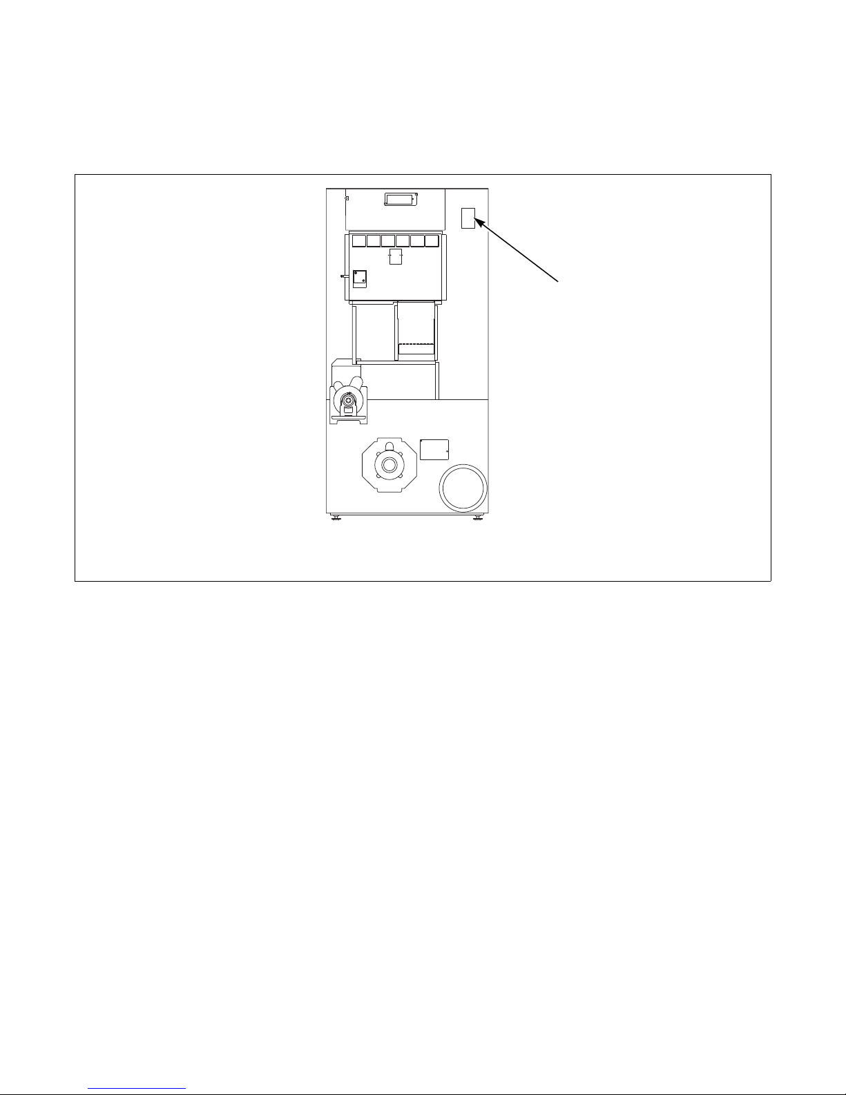
1
Serial Plate Location
When calling or writing about your product, be sure to
mention model and serial numbers. Model and serial
numbers are located on serial plate as shown.
1 Serial Plate
Customer Service
If literature or replacement parts are required, contact
the source from which the machine was purchased or
contact Alliance Laundry Systems at (920) 748-3950
for the name and address of the nearest authorized parts
distributor.
For technical assistance, call +1 (920) 748-3121.
Wiring Diagram
The wiring diagram is located inside the contactor or
junction box.
The wiring diagram part number is located in the lower
portion of the electrical data on the serial plate.
TMB2098N
12 70380601
© Copyright, Alliance Laundry Systems LLC – DO NOT COPY or TRANSMIT
Page 15
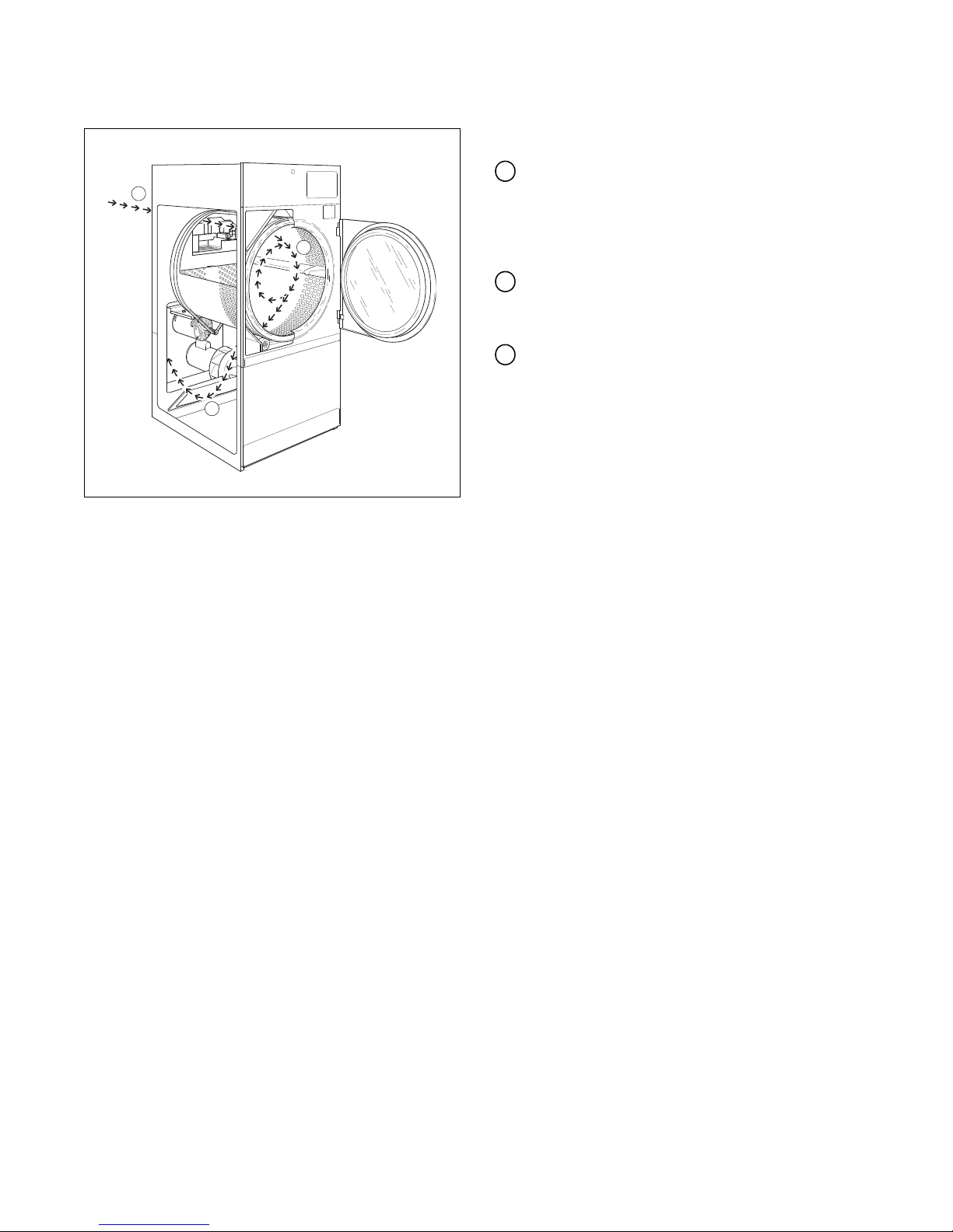
How a Tumble Dryer Works
1
2
3
T001CE3A
1
2
3
Introduction
A tumble dryer uses heated air to dry loads of laundry.
When the motor is started, the exhaust fan pulls
room temperature air in through the air intake at
the rear of the tumble dryer and over the heat
source (burner flame for gas, heating element for
electric, and coil for steam).
The heated air moves into the cylinder, where it is
circulated through the wet load by the tumbling
action of the cylinder.
The air then passes through the lint filter, exhaust
fan, and is vented to the outdoors.
70380601 13
© Copyright, Alliance Laundry Systems LLC – DO NOT COPY or TRANSMIT
Page 16
Introduction
1
2
5
4
3
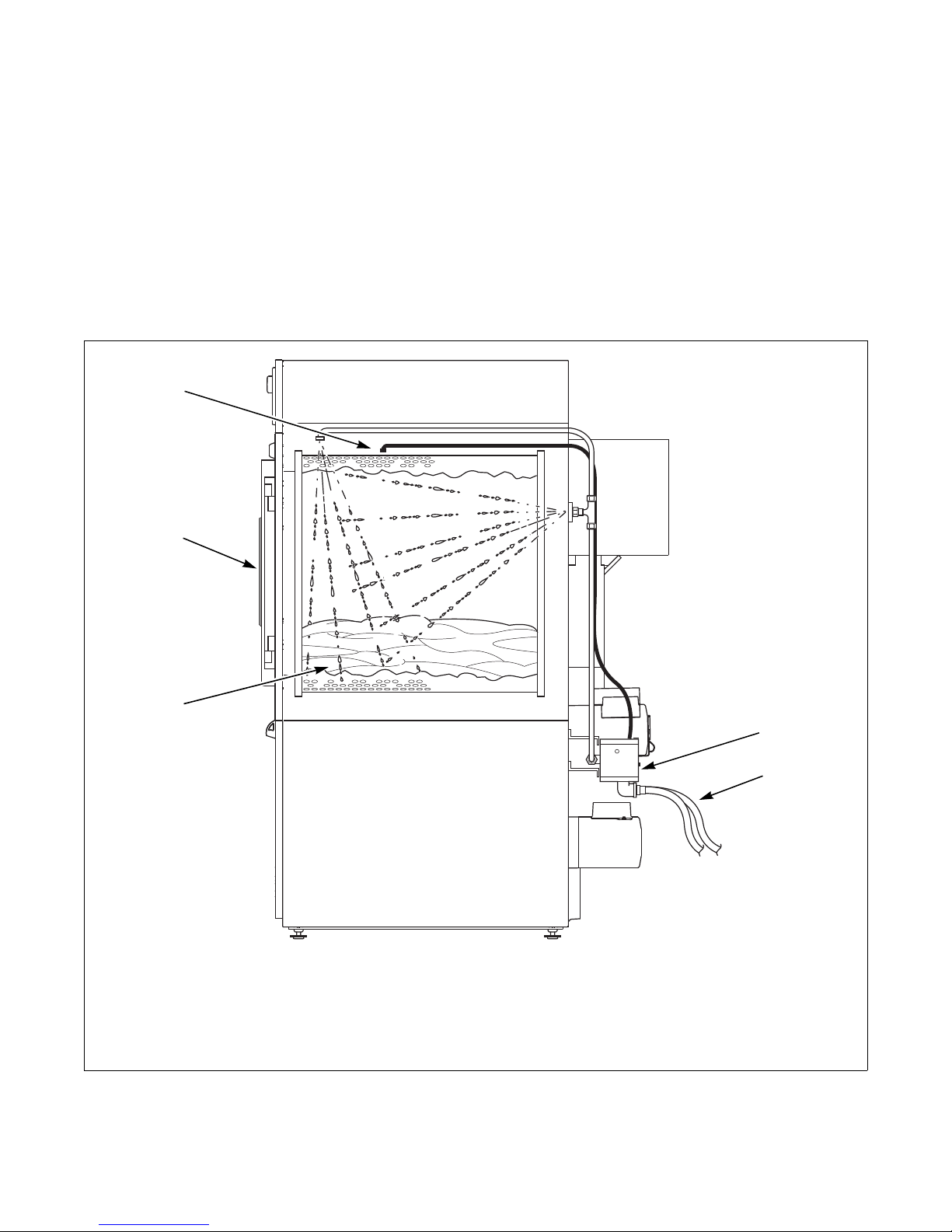
Theory of Operation
IMPORTANT: The fire suppression system is
designed to diminish a laundry fire starting inside a
fire suppression system equipped tumble dryer.
The fire suppression system is not designed to stop
or eliminate high temperature and spontaneous
combustion situations. Follow all instructions in the
installation manual to ensure the fire suppression
system operates properly. Train all operators in the
proper preventative maintenance of the fire
suppression system.
IMPORTANT: For safety purposes, do not operate
tumble dryer if a fire has occurred.
1 Te mp e ra t ur e S e ns o rs 4 Fire Suppression System Control Box
2 Loading Door 5 Water Flow to Machine
3 Load
Figure 1
TMB2257N
14 70380601
© Copyright, Alliance Laundry Systems LLC – DO NOT COPY or TRANSMIT
Page 17
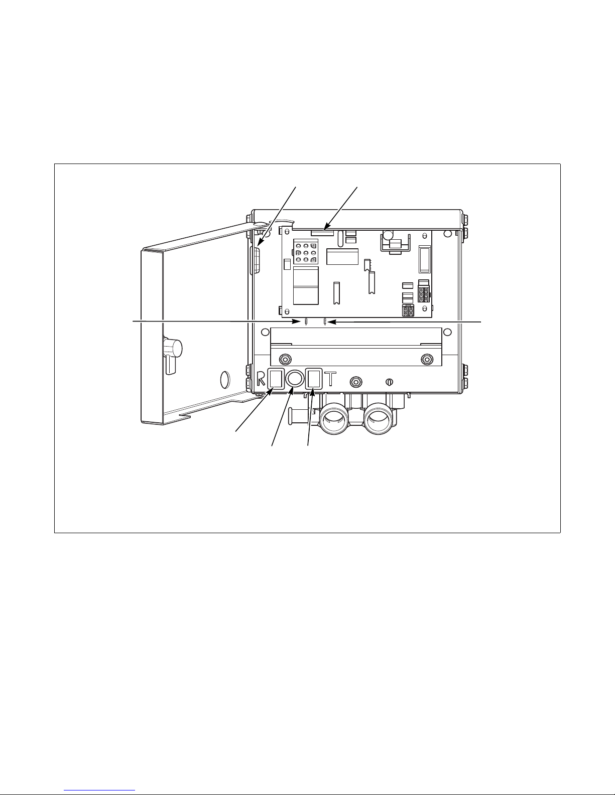
Tempe rature Sen so r
3
4
5
6
7
1
2
Two temp e rature sensors are lo c ated i n the c ylinder
area of the tumble dryer to provide temperature
readings. Refer to Figure 1 and Figure 2. These
temperature sensors will trigger a mode change based
on a pre-set temperature trip-point.
Introduction
TMB1999N
1 Opening for Auxiliary Alarm Cable 5 Light
2 Fuse 6 Reset Button
3 Auxiliary Alarm Fast-On Connection 7 Auxiliary Alarm Fast-On Connection
4 Te st Bu t to n
Figure 2
TMB1999N
70380601 15
© Copyright, Alliance Laundry Systems LLC – DO NOT COPY or TRANSMIT
Page 18
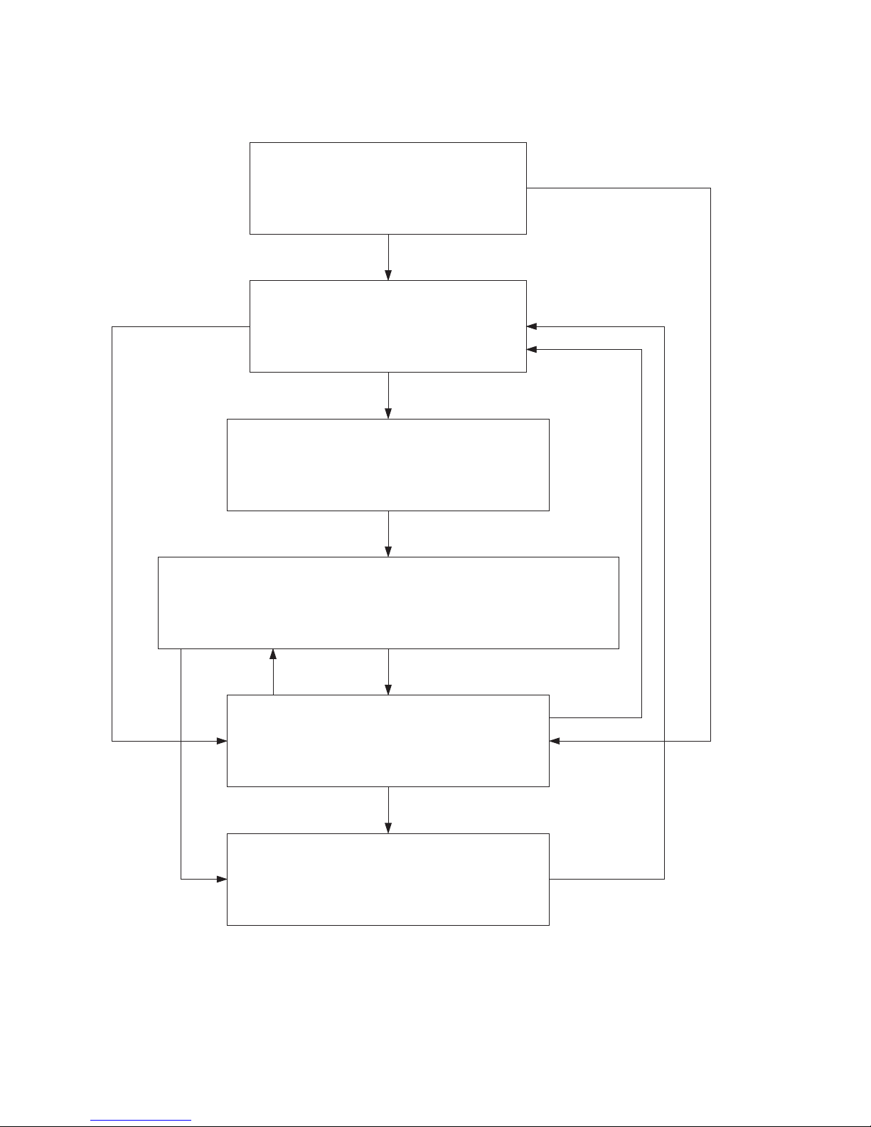
Introduction
Power-Up Mode
Sends power to control, begins a status check
of the system. Can send control into Idle Mode
or Lockout Mode.
Idle Mode
Machine is operable while it monitors
temperature sensor readings. Control will enter
Power Disconnect Mode if temperature
trip-point is exceeded.
Power Disconnect Mode
Machine is disabled and controls on front will not
operate, will enter Power Disconnect Mode for one
second, then Water On Mode.
Water On Mode
Machine is disabled and controls on front will not operate. Remain in this mode
for 90 seconds, then enter Lockout Mode. Can enter Lockout Error Mode if both
temperature sensors become open, which occurs when temperature is below
40° F (4° C). Will enter Idle Mode if reset button is pressed. Refer to
Figure 2.
Lockout Mode
Machine is disabled and controls on front will not
operate. Control monitors temperature readings. Enters
Wat er On Mode if temperat ure t ri p-point is exc eed e d.
Will enter Idle Mode if reset button is pressed.
Lockout Error Mode
Machine is disabled and controls on front will not
operate. Water dispenses for four minutes. When the
reset button is pressed, the control enters Idle
Mode.
If temper ature
trip-point exceeded
If both temperature
sensors become open
Whe n reset
button is pressed
If reset button
is pressed
Modes of Operation
16 70380601
© Copyright, Alliance Laundry Systems LLC – DO NOT COPY or TRANSMIT
Page 19

Section 3
To re d uc e th e r is k o f e l ec tri c s h oc k, fir e, exp lo s ion , s er i ou s i n ju ry or dea th:
•Disconnect electric power to the tumble dryer before servicing.
•Close gas shut-off valve to gas tumble dryer before servicing.
•Close steam valve to steam tumble dryer before servicing.
•Never start the tumble dryer with any guards/panels removed.
•Whenever ground wires are removed during servicing, these ground wires must be
reconnected to ensure that the tumble dryer is properly grounded.
W002R1
WARNING
Machine Troubleshooting
IMPORTANT: Refer to wiring diagram for aid in
testing tumble dryer components.
70380601 17
© Copyright, Alliance Laundry Systems LLC – DO NOT COPY or TRANSMIT
Page 20
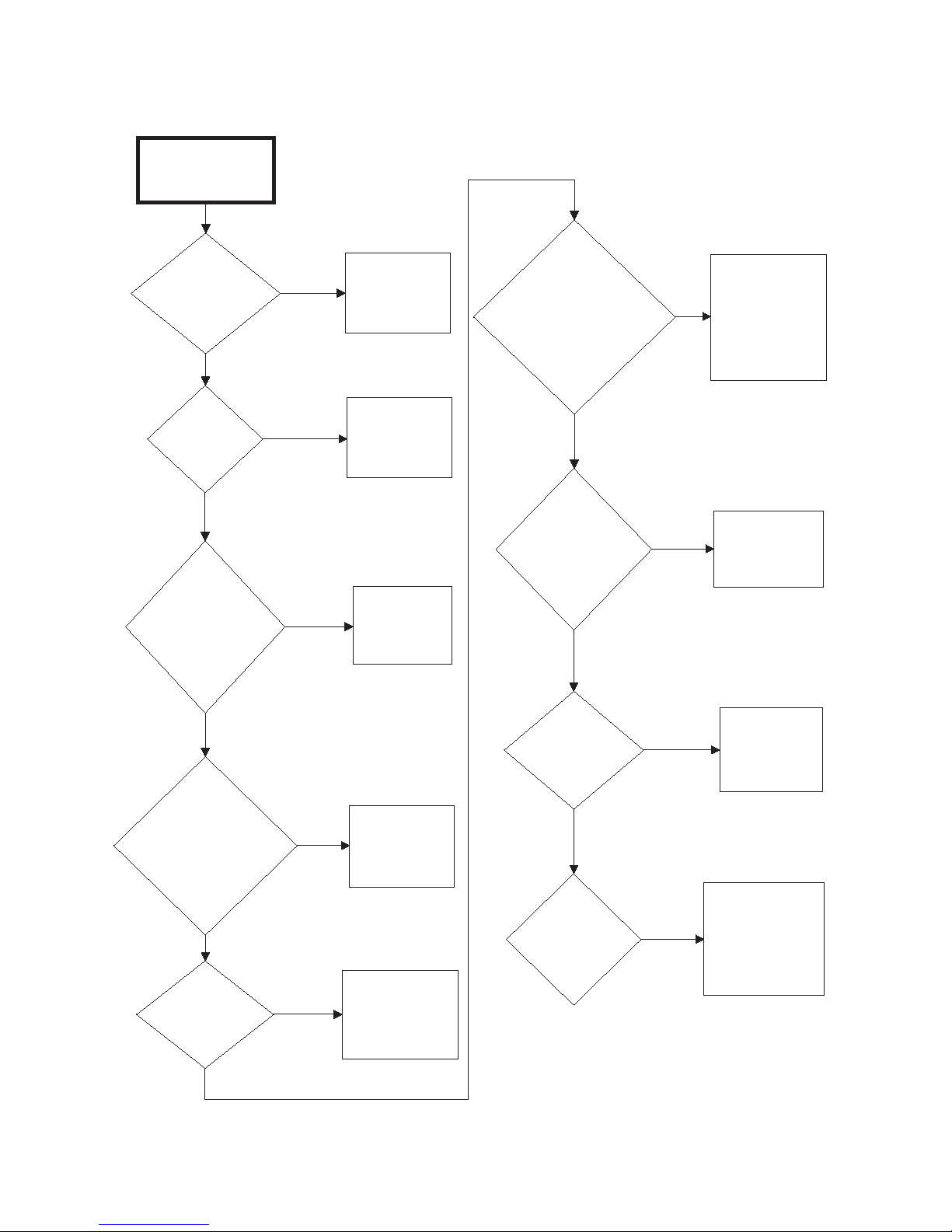
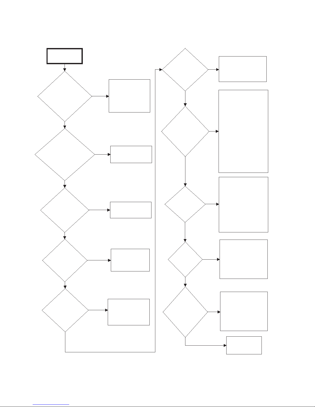
Machine Troubleshooting
Tumble Dryer
Does Not Start
Is motor
relay
inoperative?
Test relay and
replace if
necessary.
Yes
Is
loading door
open?
No
Close loading
door
completely.
Is
drying timer in
an off position
(Hybrid Timer
Models)?
Yes
Turn drying
timer on.
Check that
proper amount
of coins are
inserted.
Is the
START button
not properly
activated
(Hybrid Timer
Models)?
Press and
hold
START button
for three
seconds.
Is the
electrical power
off or circuit
breaker or fuse
blown?
Close and
lock lint
panel.
Check fuse
(in junction box)
and replace if
necessary.
Is
there a
blown fuse
on tumble
dryer?
Test coin drop
and replace if
inoperative.
Yes
Is coin drop
inoperative?
Is there an
incorrect
amount of coins
inserted into
coin drop?
No
No
Yes
No
Yes
Check power
supply, or
replace fuses.
No
Is the lint
panel
open?
No
Yes
No
Yes
Yes
TMB2036S
Yes
No
1. Tumble Dryer Does Not Start
18 70380601
© Copyright, Alliance Laundry Systems LLC – DO NOT COPY or TRANSMIT
Page 21

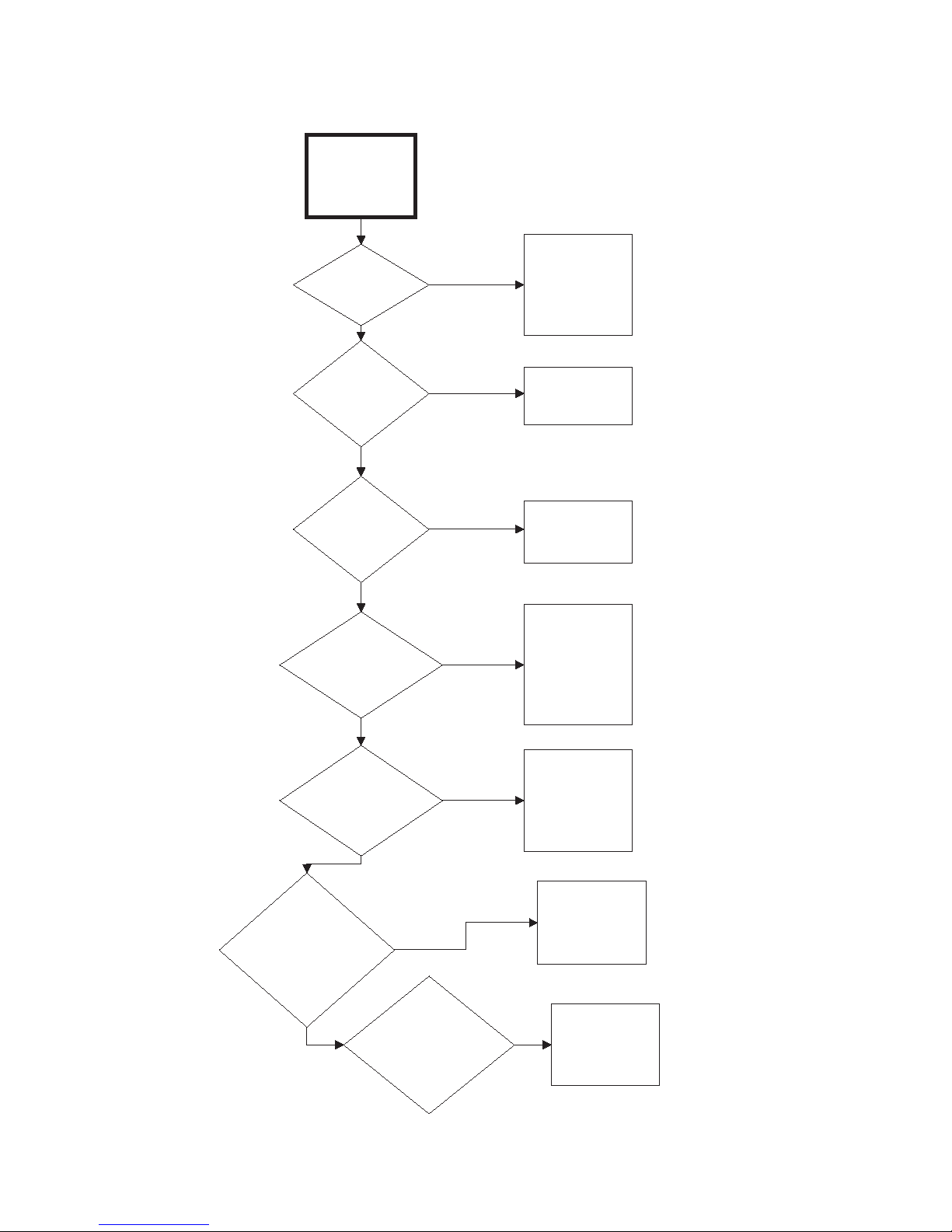
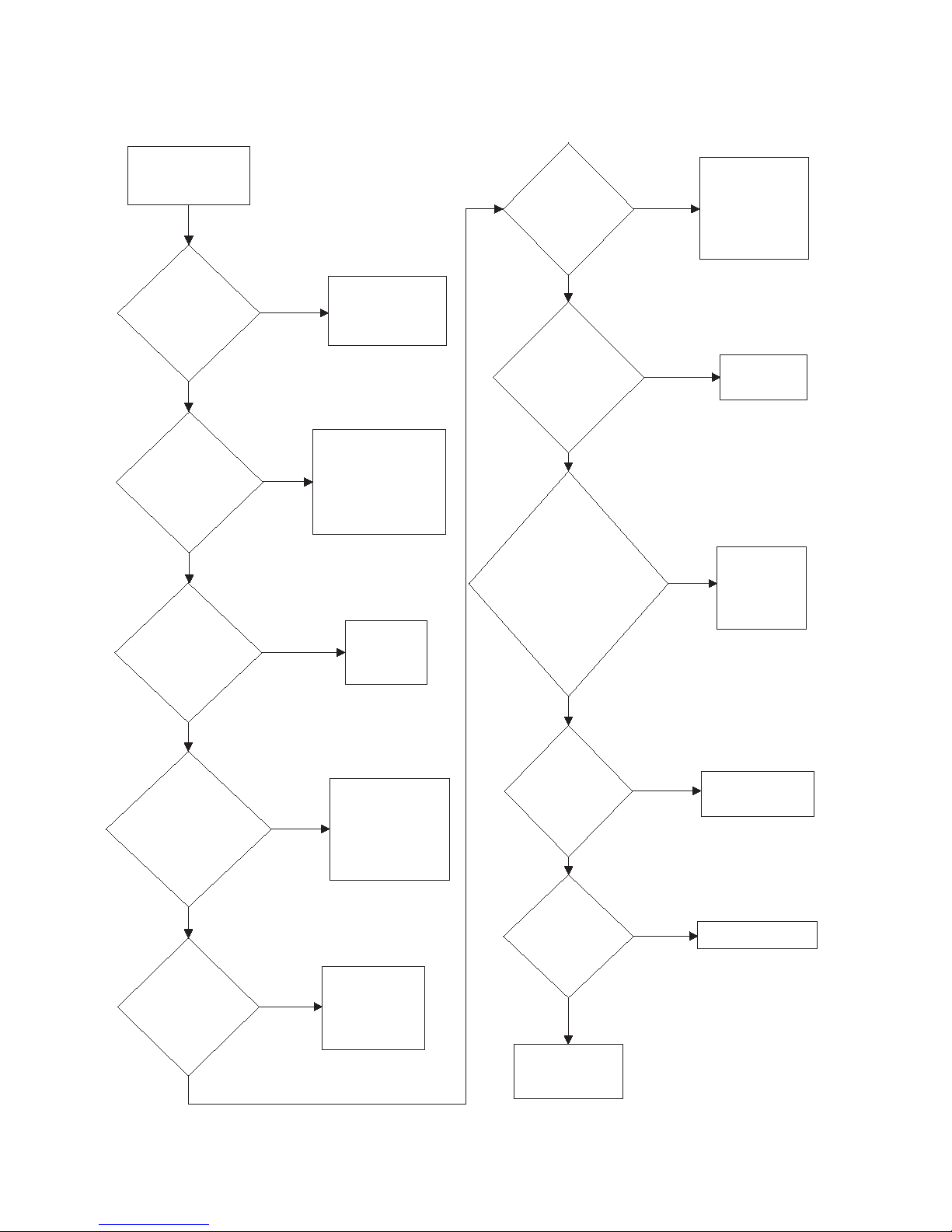
2. Motor Does Not Start
Motor Does
Not Start
Is the
electrical power
off or circuit
breaker fuse
blown?
No
Is the
loading door
switch or lint
panel switch not
closed or switch
inoperative?
Is the
door switch
improperly
adjusted?
No
Check power
supply, or replace
fuses.
Yes
Close door, panel
or test switch and
replace if
inoperative.
Yes
Refer to
Adjustments
Section for door
switch adjustment.
Yes
Is the start
circuit not
complete?
Yes
Press and hold
START button for
three seconds.
Is the motor
inoperative?
Yes
Have motor tested
and replace if
inoperative.
No
Is the
cylinder or
cylinder motor
binding?
No
Refer to wiring
diagram.
Yes
Replace fan or
motor assembly.
Yes
Replace cylinder,
bearing, rollers, or
motor assembly.
Yes
Is the
transformer
inoperative?
Yes
Test and replace
if necessary.
Is the
motor relay
inoperative?
Yes
Test relay and replace
if inoperative.
Is
the fan or fan
motor
binding?
Is there
broken, loose,
or incorrect
wiring?
No
No
No
Is the
airflow switch
inoperative
(Hyrid Timer
Models)?
Yes
Test switch,
replace or adjust
as required.
No
TMB2037S
No
No
Machine Troubleshooting
70380601 19
© Copyright, Alliance Laundry Systems LLC – DO NOT COPY or TRANSMIT
Page 22
Machine Troubleshooting
TMB1904S
Motor Overload
Protector
Cycles
Repeatedly
Is voltage
correct?
Refer to
Installation
Manual for
electrical
requirements.
Yes
Is clothes
load too
large?
No
Remove part of
load.
Yes
Is clothes
cylinder
binding?
Check cylinder
for binding.
Is wiring
adequate?
No
Yes
No
Check with
local power
company to
ensure that
wiring is
adequate.
Yes
Is make-up
air adequate?
Refer to
Installation
Manual for
make-up air
requirements.
No
Yes
Is
there lint
buildup around
tumble dryer or poor
maintenance?
Clean lint
accumulation
on and around
the motors.
No
Yes
Is there
broken, loose
or incorrect
wiring?
Refer to wiring
diagram.
No
Yes
3. Motor Overload Protector Cycles Repeatedly
20 70380601
© Copyright, Alliance Laundry Systems LLC – DO NOT COPY or TRANSMIT
Page 23
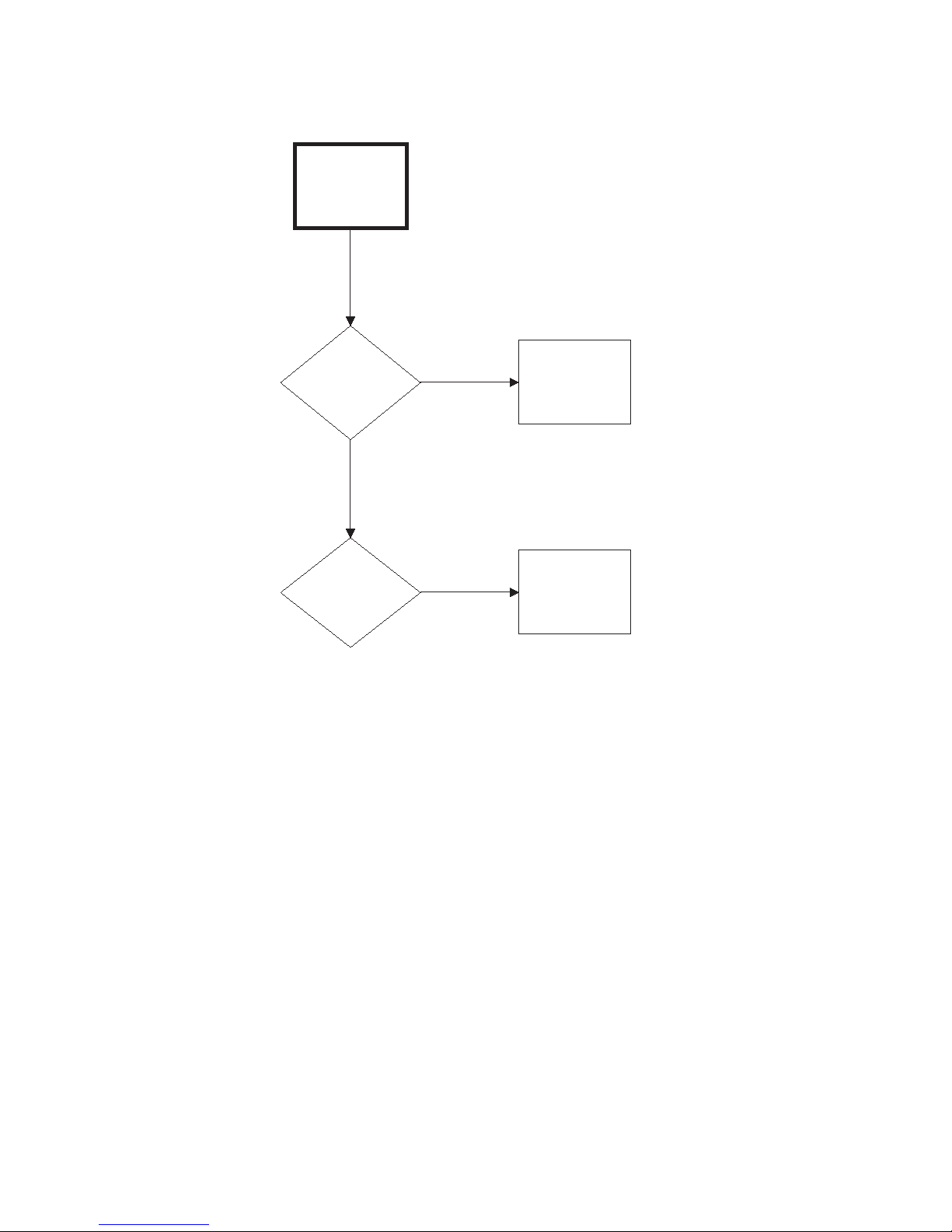
4. Motor Runs But Cylinder Does Not Turn
Motor Runs
But Cylinder
Does Not Turn
Machine Troubleshooting
Is cylinder
belt
broken?
No
Is cylinder
binding?
Yes
Yes
Replace
cylinder belt.
Check cylinder
for binding.
TMB1905S
70380601 21
© Copyright, Alliance Laundry Systems LLC – DO NOT COPY or TRANSMIT
Page 24

Machine Troubleshooting
5. Motor Does Not Stop
Motor Does
switch or lint
panel switch
not working
Not Stop
Is the door
properly?
No
Yes
Test switches
and replace if
inoperative.
Is coin drop
not working
properly?
No
Is wiring
incorrect?
No
Is electronic
control
inoperative?
No
Yes
Yes
Yes
Test coin drop
and replace if
inoperative.
Refer to wiring
diagram.
Replace
electronic
control.
Is motor
inoperative?
22 70380601
© Copyright, Alliance Laundry Systems LLC – DO NOT COPY or TRANSMIT
relay
Yes
Test relay and
replace if
inoperative.
TMB2038S
Page 25

6. No Heat Condition (Non-CE and Non-Australian Models)
To re d uce th e r is k o f e l ec tri c s hoc k, fir e, ex p los io n , s er i ous i n ju r y o r d ea t h:
•Disconnect electric power to the tumble dryer before servicing.
•Close gas shut-off valve to gas tumble dryer before servicing.
•Close steam valve to steam tumble dryer before servicing.
•Never start the tumble dryer with any guards/panels removed.
•Whenever ground wires are removed during servicing, these ground wires must be
reconnected to ensure that the tumble dryer is properly grounded.
W002R1
WARNING
Ignition Control Module Function
There are four components to the ignition system: the
module, the spark igniter, the high voltage cable and
ground wire. When 24 VAC is applied between the TH
and GND terminals on the module, the module will
send the high voltage signal to the igniter and 24 VAC
to the gas valve coils. Gas will hit the sparking igniter
and flame will be established. The igniter being
engulfed in flame will create a millivolt electric signal
that is sent back to the module by the high voltage
cable; this is what them module sees as flame
recognition. If the millivolt signal is not at the module
in ten seconds, the module will go into safety lockout.
The voltage will be cut from the igniter and gas valve
coils and will not be restored until voltage is cycled at
the module.
Machine Troubleshooting
Intermittent Heat Test Procedure
On ignition control modules with date codes higher
than 08t2, perform the following test.
Start the tumble dryer and run for 10 minutes (verify
that the tumble dryer is heating properly). After the 10
minute cycle, re-start the tumble dryer and once again
verify the unit is heating. Repeat this procedure 3
times. If the tumble dryer passes this test, the ignition
control module is operating properly and SHOULD
NOT be changed. Refer to Troubleshooting Manual
for additional service procedures.
70380601 23
© Copyright, Alliance Laundry Systems LLC – DO NOT COPY or TRANSMIT
Page 26
Machine Troubleshooting
Is the Ignition Control
Module’s red light on?
No
No
Yes
Yes
Refer to
Paragraph 7.
Replace igniter and high
voltage lead. Retest unit. If
unit still does not spark,
replace module.
No
Refer to Paragraph 7
for heat circuit
troubleshooting.
Is there
24 volts AC between
the TH and GND terminals
on the module?
Yes
No
Check wiring between
gas valve and module.
If wiring is good,
replace module.
Yes
Yes
Is there continuity
between GND terminal on
module and machine?
No No
Does the igniter
spark but no
flame is produced?
No
Yes
Is there
24 volts AC at the gas
valve coils when igniter
is sparking?
Is the igniter
positioned properly
in the flame, and does the
flame look good?
Does the igniter
spark?
Verify that gas is supplied
to the machine. If gas and
voltage are present,
replace gas valve or coils.
Does the flame turn
off after igniter
stops sparking?
No
Yes
Replace module.
Adjust position of
igniter and retest.
Yes
Verify machine is
properly grounded.
Replace igniter and
high voltage lead.
Retest unit. If it still
does not sense flame,
replace module.
TMB2395S
6. No Heat Condition
24 70380601
© Copyright, Alliance Laundry Systems LLC – DO NOT COPY or TRANSMIT
Page 27
7. Burner Does Not Ignite
Burner Does
Not Ignite
Is there
an improper or
inadequate exhaust
system?
No
Are there
blown fuses or
tripped circuit breakers
in external electric
supply line?
Yes
exhaust system
Yes
Refer to
Installation
Manual for
requirements.
Check fuses or
circuit breaker.
Is
stove limit
thermostat 2
inoperative?
No
Is
there an
insufficient gas
supply?
No
Machine Troubleshooting
Test thermostat 2
Yes
Yes
and replace if
inoperative.
Open partially closed
gas shut-off valve, or
correct low gas
pressure. Check
manifold pressure
and adjust to
pressure specified on
serial plate. If
pressure cannot be
obtained, have your
local gas company
check main gas
pressure.
No
Is
drying
selector in the
“Cool Down”
portion of
cycle?
No
Is
the cabinet
thermostat
inoperative?
No
Is
stove limit
thermostat 1
inoperative?
Yes
Yes
Yes
Reset switch on
microprocessor.
Test thermostat
and replace if
inoperative.
Test thermostat 1
and replace if
inoperative.
Are the
orifices
incorrect?
No
Is there
lint
buildup?
No
Is there
inadequate
ductwork and
make-up
air?
Yes
Yes
Yes
Tumble Dryer is
equipped for type of
gas specified on
serial plate. If
orifices are
different from that
specified on serial
plate, obtain and
install correct orifices.
Clean lint
compartment. Check
damper for lint
accumulation. Check
ductwork for lint
buildup.
Refer to Installation
Manual to ensure
that ductwork and
make-up air
openings are sized
accurately.
No
70380601 25
© Copyright, Alliance Laundry Systems LLC – DO NOT COPY or TRANSMIT
No
Continued on
next page
TMB2187S-a
Page 28
Machine Troubleshooting
Continued from
previous page
Is
there an
improper igniter
to burner
clearance?
Are valve coils
inoperative?
No
Clearance
should be
0.110 - 0.140
inch (2.79 - 3.55
mm).
Yes
Check valve
coils and
replace if
necessary.
Yes
Is
there a
blown fuse on
tumble
dryer?
Yes
Check fuse
(located in
control box)
and replace if
necessary.
Is
gas shut-off
valve in the
closed
position?
Yes
Open shut-
off valve.
Is
motor switch
inoperative?
No
Replace IEI
control.
Yes
Replace motor.
Yes
Is the
IEI control
inoperative?
TMB2187S-b
Yes
Connect
ground wire
to ground
terminal.
Is the
ground wire
from Instant
Electronic Ignition
(IEI) board not
connected to
ground
terminal?
No
Is
there broken,
loose or incorrect
wiring?
Yes
Refer
to wiring
diagram.
Is the lint
panel not
closed
properly?
Yes
Unlock and open
lint panel. Close
panel ensuring a
tight fit, then lock.
Is the
airflow switch
inoperative?
Test switch
and replace
if inoperative.
Yes
No
No
No
No
No
No
Continued on
next page
No
7. Burner Does Not Ignite (continued)
26 70380601
© Copyright, Alliance Laundry Systems LLC – DO NOT COPY or TRANSMIT
Page 29

7. Burner Does Not Ignite (continued)
c
Continued from
previous page
Machine Troubleshooting
Is there
an inoperative
microprocessor or
hybrid timer?
No
Is
wrong
transformer
configuration
harness
installed?
No
Is Instant
Electronic
Ignition (IEI)
control in safety
lockout?
Yes
Yes
Yes
Test and replace
as needed.
Check incoming
voltage and install
correct
configuration
harness.
Reset IEI control by
opening and closing
loading door. (Non-
CE models only)
Reset IEI by
pressing reset
button on back of
unit. (CE models
only)
70380601 27
© Copyright, Alliance Laundry Systems LLC – DO NOT COPY or TRANSMIT
TMB2187S-
Page 30

Machine Troubleshooting
Burner Ignites
and Goes Out
Repeatedly
Is there
insufficient
gas
pressure?
Check gas
supply and
pressure.
Yes
Is the
cabinet
thermostat
inoperative?
Yes
Test thermostat
and replace if
inoperative.
Is the
exhaust system
improper or
inadequate?
Yes
Refer to
Installation
Manual for
exhaust
system
requirements.
No
No
Does
tumble dryer have
improper
orifices?
Yes
Tumble Dryer is
equipped for
type of gas
specified on serial
plate. If orifices are
different from that
specified on serial
plate, obtain and
install correct
orifices.
No
Is
there excessive
igniter to burner
clearance?
Yes
Refer to
Paragraph 43.
Is
there inadequate
make-up air?
Yes
Refer to
Installation
Manual for
make-up air
requirements.
No
Is the
thermistor
inoperative?
Yes
No
Replace
thermistor.
Is the control
heater relay
malfunctioning?
Yes
Replace control.
No
Is there
broken, loose
or incorrect
wiring?
Yes
Refer to wiring
diagram.
No
Yes
Repair damper to
working order.
Are the back
draft dampers
locked in close
position?
No
TMB1908S
No
8. Burner Ignites and Goes Out Repeatedly
28 70380601
© Copyright, Alliance Laundry Systems LLC – DO NOT COPY or TRANSMIT
Page 31

9. Burner Does Not Shut Off
Burner Does
Not Shut Off
Are there
impurities on gas
valve seat,
preventing valve
from closing?
Yes
Machine Troubleshooting
Replace gas
valve.
No
Is wiring
correct?
No
Is control heater
relay
malfunctioning?
Yes
Yes
Refer to wiring
diagram.
Replace
control.
TMB1909S
70380601 29
© Copyright, Alliance Laundry Systems LLC – DO NOT COPY or TRANSMIT
Page 32

Machine Troubleshooting
10. Clothes Do Not Dry
Clothes Do Not
Dry
Is there
enough heating
time allocated for
the load?
Yes
Start cycle again
with enough time to
dry load.
Does
the burner ignite
and go out
repeatedly?
No
Yes
Refer to
Paragraph 7.
No
Is the burner not
igniting?
No
Is there
too much water in
articles being
dried?
No
Is
the clothes
load too
large?
No
Yes
Yes
Yes
Refer to
Paragraph 6.
Remove excess
water.
Remove part of
load. Maximum
load is 25 pound
dry weight (cotton
load) for 25 pound
tumble dryer, etc.
Is
the drying
selector
improperly
set?
No
Is
the voltage
incorrect?
No
Is there
inadequate
make-up
air?
No
Is the
exhaust duct to
the outside
blocked?
Yes
Yes
Yes
Set selector
for higher
setting.
Refer to Installation
Manual for electrical
requirements.
Refer to Installation
Manual for make-up
air requirements.
Yes
Clean duct to
remove blockage.
Is the
exhaust system
improper or
inadequate?
No
Yes
30 70380601
Refer to Installation
Manual for exhaust
© Copyright, Alliance Laundry Systems LLC – DO NOT COPY or TRANSMIT
system
requirements.
No
Continued on
next page
TMB1910S-a
Page 33

10. Clothes Do Not Dry (continued)
Continued from
previous page
Machine Troubleshooting
Is the lint screen
clogged?
No
Is the thermistor
inoperative?
No
Yes
Yes
Clean lint screen.
Replace thermistor.
Is the
exhaust
damper
binding?
No
Is the
cylinder speed
too fast?
No
Is airflow switch
bracket mounted
properly?
Yes
Yes
Adjust damper so it
turns freely.
Check belt is not
riding on outer
diameter of motor
pulley.
Check for proper
alignment: make
Yes
sure locator pins
are securely in
place and tighten
mounting screws.
70380601 31
© Copyright, Alliance Laundry Systems LLC – DO NOT COPY or TRANSMIT
TMB1910S-b
Page 34

Machine Troubleshooting
11. Tumble Dryer Overheating
Tumble Dryer
Overheating
Does
tumble dryer
have incorrect
main burner
orifices?
No
Is gas
pressure too high or
low?
No
Is the
make-up air
inadequate?
No
Is there
lint buildup?
No
Is the
exhaust system
restricted or
inadequate?
No
Yes
Yes
Yes
Yes
Yes
Obtain and install
correct orifices.
Adjust gas pressure
as specified on
serial plate.
Refer to Installation
Manual for make-up
air requirements.
Clean lint
compartment. Check
damper for lint
accumulation. Check
ductwork for lint
buildup.
Remove obstruction
or lint build up from
exhaust ductwork.
Refer to Installation
Manual for exhaust
system
requirements.
Is the
thermistor
sensor
inoperative?
No
Is the
exhaust
damper
binding?
No
Is the
control heater
relay
malfunctioning?
No
Are
the safety
covers missing,
allowing
cool air to enter
tumble
dryer?
No
Is the
lint screen
clogged with
fabric
softener?
No
Are there
holes in cabinets
due to foreign
objects?
Yes
Yes
Ye s
Yes
Ye s
Ye s
Check wiring to
ensure thermistor
is connected.
Replace
thermistor if
necessary.
Remove lint build-
up on thermistor.
Adjust damper
so it turns
freely.
Replace control.
Replace covers.
Replace lint
screen.
Repair/replace
cabinet
components.
32 70380601
© Copyright, Alliance Laundry Systems LLC – DO NOT COPY or TRANSMIT
TMB1911S
Page 35

12. Burner Not Burning Properly
Burner Not Burning
Properly
Is there lint/dirt in
burner tube?
Is the gas
pressure too high
or low?
No
Disassemble
burner and
blow out the dirt.
Yes
Check serial
plate on back of
tumble dryer for
correct gas
pressure.
Yes
Is
the airflow
switch not
functioning
properly?
Yes
Replace airflow
switch.
Is there
inadequate
make-up
air?
Yes
Refer to Installation
Manual for make-up
air requirements.
TMB1912S
No
Yes
Clean off lint.
Is there lint buildup
around gas valve
spud?
No
Does the
tumble dryer have
incorrect
orifices?
Yes
Tumble Dryer is
equipped for the
type of gas specified
on serial plate. If
orifices are different
from that specified
on serial plate,
obtain and install
correct orifices.
Is the
exhaust duct
restricted or
blocked?
Yes
Disassemble
and clean
exhaust system.
No
No
No
Machine Troubleshooting
70380601 33
© Copyright, Alliance Laundry Systems LLC – DO NOT COPY or TRANSMIT
Page 36

Machine Troubleshooting
Loading Door
Opens During
Operation
Is
tumble dryer
improperly
leveled?
Refer to Installation
Manual for leveling
leg adjustment.
Is clothes
load too
large?
Remove part of load and
restart tumble dryer.
Is loading
door strike
adjusted
incorrectly?
Refer to
Adjustments
Section for strike
adjustment.
Yes
No
Yes
No
Yes
TMB1913S
13. Loading Door Opens During Operation
34 70380601
© Copyright, Alliance Laundry Systems LLC – DO NOT COPY or TRANSMIT
Page 37

14. Cylinder Continues to Spin with Door Open
NOTE: All tumble dryer panels must be in place and on the
machine for proper operation.
Cylinder
Continues To
Spin With Door
Open
Machine Troubleshooting
Is relay
inoperative?
Yes
Replace relay
in control box.
TMB1914S
70380601 35
© Copyright, Alliance Laundry Systems LLC – DO NOT COPY or TRANSMIT
Page 38

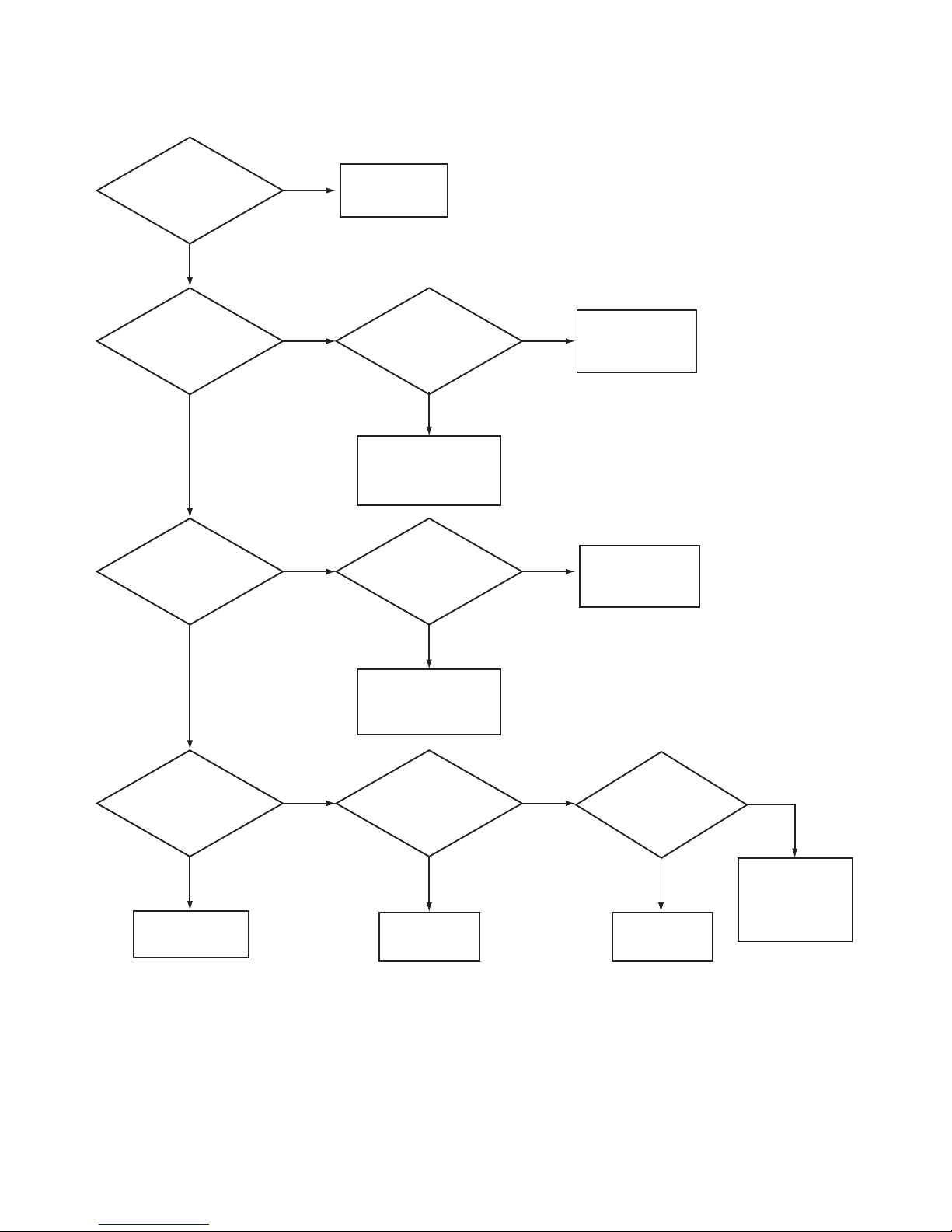
Machine Troubleshooting
Coin Does Not Fall
Into Coin Vault or Coin
Drop Sensor Does Not
Register That Coin
Has Been Entered
Is proper
electrical
power
supplied to
coin drop?
Incorrect electrical
connection may
prevent coins from
registering in coin drop.
Refer to wiring
diagram.
No
Is
machine
level?
Machines that are not
level may prevent coins
from following through
required check stages
of drop. Refer to
Installation Manual
for instructions on
leveling machine.
Is coin
drop
clean?
Residue or lint build-up
may prevent coins from
following through
required check stages
of drop. Clean coin
drop.
Yes
No
Yes
No
TMB1915S
Is sensor
operative?
Yes
Replace coin drop
sensor.
No
15. Coin Does Not Fall into Coin Vault or Coin Drop Sensor Does Not Register
that Coin Has Been Entered
IMPORTANT: Never use oil to correct coin drop problem. Oil residue will prevent coins from rolling
properly.
IMPORTANT: Do not bend or damage mechanical parts within coin drop.
36 70380601
© Copyright, Alliance Laundry Systems LLC – DO NOT COPY or TRANSMIT
Page 39

Machine Troubleshooting
MIX7B
Coin Drop
Cover
Coin Return
Button
Tension Spring
MIX6B
Coin Drop
Cover
DRY2088N
Cover Catch
Tension Spring
Small Flathead
Screwdriver
Right Side of
Tension Spring
Left Tab
MIX3B
Tabs
Center Tab
Troubleshooting Coin Drop
If coin drop is not accepting coins, perform the
following:
1. Clean coin drop. Refer to Paragraph 23.
2. On electronic coin drops with an old-style
tension spring (shown in Figure 3 and Figure 5),
test and replace tension spring using the
following instructions.
Remove Coin Drop From Machine
1. Disconnect electrical power to machine and drop.
2. Remove coin drop from machine.
Test Te ns io n Spr ing
1. Push coin return button to open and close coin
drop cover to clear possible coin jams. Refer to
Figure 3.
Replace Tension Spring
1. Move tension spring downward until cover catch
is free. Refer to Figure 5.
Figure 5
2. Open cover for coin drop.
3. Place a small flathead screwdriver under right
side of tension spring and lift up. Refer to
Figure 6.
Figure 3
2. Manually hold down coin drop cover and insert
coin. Refer to Figure 4.
Figure 4
3. If coin drop now operates properly, replace
tension spring using instructions on following
pages.
MIX2B
Figure 6
4. Use screwdriver to move spring approximately 3
mm to left.
5. Lift spring over left tab. Refer to Figure 6.
6. Rotate spring clockwise, 40 to 60 degrees, until it
is free from right tabs. Refer to Figure 7.
70380601 37
© Copyright, Alliance Laundry Systems LLC – DO NOT COPY or TRANSMIT
Figure 7
Page 40

Machine Troubleshooting
MIX4B
Clip
MIX8B
Slot
MIX5B
Small Flat
Screwdriver
Center
Tab
Left Tab
7. Use screwdriver to remove spring from center
tab. Refer to Figure 7.
8. Lift spring, with attached clip, off drop.
9. Remove clip from spring. Refer to Figure 8.
Figure 8
10. Attach clip to new tension spring, Part No. 209/
00598/02.
11. Place clip, installed on spring, in slot on coin
drop. Refer to Figure 9.
13. Lift spring gently to place in position under left
tab.
14. Push spring to right until it snaps into position.
Refer to Figure 6.
15. Close coin drop cover.
16. Move tension spring over cover catch. Refer to
Figure 5.
Reinstall Coin Drop Into Machine
1. Reinstall coin drop into machine.
2. Reconnect electrical power to machine and drop.
3. Add a coin to drop to verify that coin drop is
operating properly and that electrical connection
is working properly.
Figure 9
12. Use a small flathead screwdriver to push spring
under center tab. Refer to Figure 10.
Figure 10
38 70380601
© Copyright, Alliance Laundry Systems LLC – DO NOT COPY or TRANSMIT
Page 41

Machine Troubleshooting
16. Cylinder Is “Stained”
Over time, the cylinder and cylinder backs of tumble
dryers can become “stained” from various melted
fabrics. These discolored areas can be removed by
scrubbing the inside of the cylinder with cleaner and a
cleaning pad, such as Scotch- Brite®.
IMPORTANT: Do not use a steel wool pad to clean
the cylinder. Steel wool can damage your machine.
Galvanized Cylinders
For galvanized cylinders, use an all-purpose cleaner
(such as 409®) and a cleaning pad (such as ScotchBrite®) to clean the inside of the cylinder.
1. Spray the cleaner on the discolored areas and let
soak for a few minutes.
2. Using the pad, scrub the areas until the
discoloration is removed.
3. Repeat steps 1-2 as necessary.
4. Thoroughly wipe the entire cylinder after
cleaning to insure the cleaner has been removed.
Stainless Steel Cylinders
For stainless steel cylinders, use a heavy duty powder
cleanser (such as Zud®) and a cleaning pad (such as
Scotch- Brite®) to clean the inside of the cylinder.
1. Using a water spray bottle, wet the cylinder and
cylinder back.
2. Sprinkle cleanser onto the pad and scrub the
discolored areas.
3. Repeat steps 1-2 as necessary.
4. Thoroughly wipe the entire cylinder after
cleaning to insure the cleanser has been removed.
70380601 39
© Copyright, Alliance Laundry Systems LLC – DO NOT COPY or TRANSMIT
Page 42

Section 4
Fire Supression System Troubleshooting
A water discharge or system fault is indicated when
the fire suppression system control box light is on.
IMPORTANT: When handling electronic controls,
use a ground wrist strap. Due to the sensitivity of
electronic controls, careful handling is required.
Wrist strap, cord and alligator clip are designed to
carry away any electrostatic charge from your
body and to direct charge to an available ground.
By using this static protection device, potential
electrostatic discharge problems associated with
handling of electronic control will be minimized.
Always handle electronic control by its metal edges.
40 70380601
© Copyright, Alliance Laundry Systems LLC – DO NOT COPY or TRANSMIT
Page 43

Fire Supression System Troubleshooting
To re d uc e t h e r is k o f e l ec tri c s hoc k, fi r e, ex p lo s ion , s er i ou s i n ju ry or de a th:
•Disconnect electric power to the tumble dryer before servicing.
•Close gas shut-off valve to gas tumble dryer before servicing.
• Close steam valve to steam tumble dryer before servicing.
•Never start the tumble dryer with any guards/panels removed.
•Whenever ground wires are removed during servicing, these ground wires must be
reconnected to ensure that the tumble dryer is properly grounded.
W002R1
WARNING
TMB2196N
17. Tumble Dryer Does Not Operate and Light Is On
Are there signs of
fire or water
discharge?
No
Does tumble dryer
operate after
pressing the reset
button for at least
one second?
No
Is there power
(5 Volts DC) between
H2-3 and H2-4 of
the reset button?
Yes
Replace reset
button.
Yes
Was there a fire?
Replace tumble dryer.
No
Yes
Call the fire department.
DO NOT disconnect electric power to the tumble dryer.
DO NOT disconnect water to the tumble dryer.
DO NOT touch the tumble dryer.
Yes
No
Retest.
(Extreme cold
weather will cause a
system shutdown.)
Disconnect
power to
tumble dryer.
Run a
continuity test
across the
reset switch.
Is it shorted?
Yes
Replace
switch.
Refer to
Water Discharge
No Fire flowchart.
Replace fire
suppression
system
control
board.
Reset fire
suppression
system
control.
Retest.
Is the resistance for
both temperature
sensors within the
acceptable range?*
Sensor 1 H4-1 to H4-2
Sensor 2 H4-4 to H4-3
No
Replace
temperature
sensors.
Replace fire
Yes
suppression
system
control board.
Acceptable resistance ranges from
*
150K Ohms to 19K Ohms in temperature
ranges from 40° to 120° F (4° to 48° C).
Retest.
Reset fire
suppression
system
control.
Retest.
70380601 41
© Copyright, Alliance Laundry Systems LLC – DO NOT COPY or TRANSMIT
TMB2196N
Page 44

Fire Supression System Troubleshooting
To re d uc e t h e r is k o f e l ec tri c s hoc k, fi r e, ex p lo s ion , s er i ou s i n ju ry or de a th:
•Disconnect electric power to the tumble dryer before servicing.
•Close gas shut-off valve to gas tumble dryer before servicing.
• Close steam valve to steam tumble dryer before servicing.
•Never start the tumble dryer with any guards/panels removed.
•Whenever ground wires are removed during servicing, these ground wires must be
reconnected to ensure that the tumble dryer is properly grounded.
W002R1
WARNING
TMB2258N
Is the resistance for
both temperature
sensors within the
acceptable range?*
Sensor 1 H4-1 to H4-2
Sensor 2 H4-4 to H4-3
Replace fire
suppression
system
control board.
Yes
Acceptable resistance ranges from
150K Ohms to 19K Ohms in temperature
ranges from 40˚ to 120˚ F (4˚ to 48˚ C).
Reset fire
suppression
system
control.
Retest.
Replace
temperature
sensors.
No
Retest.
*
Is the unit
a reversing
model?
No
No
Yes
Set
control
to
nonreversing.
Electric Models:
Set to no heat.
Start unit.
Is the
cylinder
turning
clockwise?
Is the vent
blocked or
restricted?
Clear vent/ease
restrictions.
Refer to
Installation
Manual for
proper venting.
Retest
system.
Retest
system.
Correct input
wiring to
change phase.
(Fan is
spinning
backward.)
Yes
Yes No
No
TMB2258N
18. Water Discharge, but No Fire
IMPORTANT: Electric Models: If water has discharged into machine, you MUST perform this diagnostic
test with NO HEAT to the machine.
42 70380601
© Copyright, Alliance Laundry Systems LLC – DO NOT COPY or TRANSMIT
Page 45

Fire Supression System Troubleshooting
To re d uc e t h e r is k o f e l ec tri c s hoc k, fi r e, ex p lo s ion , s er i ou s i n ju ry or de a th:
•Disconnect electric power to the tumble dryer before servicing.
•Close gas shut-off valve to gas tumble dryer before servicing.
• Close steam valve to steam tumble dryer before servicing.
•Never start the tumble dryer with any guards/panels removed.
•Whenever ground wires are removed during servicing, these ground wires must be
reconnected to ensure that the tumble dryer is properly grounded.
W002R1
WARNING
TMB2198N
Is voltage to fire
suppression system
control 24 VAC
between
H1-7 and H1-1?
Is fuse F1 on fire
suppression system
control blown?
Is voltage to light
2 VDC between
H2-1 and H2-2?
Replace light.
Yes
Replace fire
suppression system
control board.
No
Reset fire
suppression
system
control board.
Retest
Check power
to tumble dryer
and
connections
to junction
box.
No
Yes
Replace fuse. Retest fuse.
Yes
No
Retest
TMB2198N
19. Tumble Dryer Does Not Operate and Light Is Off
70380601 43
© Copyright, Alliance Laundry Systems LLC – DO NOT COPY or TRANSMIT
Page 46

Fire Supression System Troubleshooting
To re d uc e t h e r is k o f e l ec tri c s hoc k, fi r e, ex p lo s ion , s er i ou s i n ju ry or de a th:
•Disconnect electric power to the tumble dryer before servicing.
•Close gas shut-off valve to gas tumble dryer before servicing.
• Close steam valve to steam tumble dryer before servicing.
•Never start the tumble dryer with any guards/panels removed.
•Whenever ground wires are removed during servicing, these ground wires must be
reconnected to ensure that the tumble dryer is properly grounded.
W002R1
WARNING
TMB2199N
20. Tumble Dryer Operates, but Water Does Not Discharge and Light Is On
Verify water is
supplied to valve at
the proper pressure
and flow rate. Refer
to Installation
section.
Yes
Turn off t umble dr yer.
Are water inlet
screens clogged?
No
Reset fire
suppression
system control.
Retest
Using an AC
voltmeter, within 90
seconds, is there
voltage to the water
manifold valve?
No
Is wiring between
valve and fire
suppression system
control good?
Yes
Replace fire
suppression system
control.
No
requirements of
Yes
screens, then
turn on water.
Yes
No
Make
corrections to
meet water
system.
Clean inlet
Disconnect
hose from
water valve
outlet.
Correct wiring.
Refer to wiring
diagram on the
following page.
suppression
suppression
Retest
Reset fire
system
control.
Reset fire
system
control.
Are water hoses
or the manifold
nozzle clogged?
suppression system
Does water
come out of
valve?
Yes
Clear any
debris.
Reset fire
control.
Retest
Retest
No
Replace water
valve.
Retest
Retest
44 70380601
© Copyright, Alliance Laundry Systems LLC – DO NOT COPY or TRANSMIT
TMB2199N
Page 47

Fire Supression System Troubleshooting
FIRE
SUPPRESSION
SYSTEM
CONTROL
BOARD
TMB2200N
70380601 45
© Copyright, Alliance Laundry Systems LLC – DO NOT COPY or TRANSMIT
Page 48

Section 5
To re d uc e th e r is k o f e l ec tri c s h oc k, fir e, exp lo s ion , s er i ou s i n ju ry or dea th:
•Disconnect electric power to the tumble dryer before servicing.
•Close gas shut-off valve to gas tumble dryer before servicing.
•Close steam valve to steam tumble dryer before servicing.
•Never start the tumble dryer with any guards/panels removed.
•Whenever ground wires are removed during servicing, these ground wires must be
reconnected to ensure that the tumble dryer is properly grounded.
W002R1
WARNING
Adjustments
21. Loading Door Switch
The door switch should be adjusted so the
cylinder stops when door is opened 2 inches (51
mm), plus or minus 1/4 inch (6 mm). The switch
is normally open and is closed when the door is
closed. If adjustment is needed, proceed as
follows: Refer to Figure 11.
a. Close door and start tumble dryer. Slowly
open loading door. Cylinder and heat system
should shut off when door is open 2 inches
(51 mm), plus or minus 1/4 inch (6 mm).
b. Slowly close loading door. When door is 2
inches or less from being fully closed, the
switch actuator on the door should contact the
switch plunger and depress it enough to close
the switch with an audible “click”.
c. If switch actuator does not depress the switch
plunger enough to operate the switch, bend
switch actuator OUTWARD and repeat steps
“a” and “b”.
22. Loading Door Strike
Refer to Figure 11.
The door strike must be adjusted so that sufficient
tension holds loading door closed against the
force of a load tumbling against it. The door is
properly adjusted when 8-15 lbs. (3.60-6.75 kg)
of pull is required to open door.
If adjustment is needed, follow these steps:
a. Open loading door.
b. Loosen jamnut.
c. Turn door strike screw in or out as required.
d. Retighten jamnut.
Loading
Door
Switch
Actuator
Figure 11
Jamnut
Door Strike
Screw
T280SE3C
46 70380601
© Copyright, Alliance Laundry Systems LLC – DO NOT COPY or TRANSMIT
Page 49

23. Aligning Door Strike
DRY208
Catch
Spring
Cover
Spring
If the door acorn nut is breaking or the door catch
is prematurely wearing (refer to Figure 11), a
door adjustment may be necessary to align the
two striking surfaces.
a. Visually check door strike to catch position to
determine if door is striking low or high.
b. Make sure the door frame to the tumble dryer
hinge mounting screws are secure.
c. To adjust the strike position slightly, loosen
both hinge hex bolts until the door frame can
be moved. If the door is striking low, lift up
on the door and while maintaining pressure
tighten both hinge bolts. If the door is striking
high, push down on the door and while
maintaing pressure tighten both hinge bolts.
Re-check strike position and repeat until
position is correct.
Open cover for coin drop. Refer to
(2)
Figure 13.
Adjustments
DRY2089N
24. Cleaning Coin Drop
NOTE: The coin drop should be cleaned once a
year. Clean the drop more often if it is exposed to
high levels of residue or lint build-up.
a. Disconnect electrical power to machine and
drop.
b. Remove coin drop from machine.
c. Check the spring style of coin drop.
Coin Drops with Old-Style Spring (refer to
Figure 12):
(1) Move spring downward until cover catch is
free. Refer to Figure 12.
NOTE: Do not lift or overbend the spring in any
direction.
Figure 13
Coin Drops with New-Style Spring (refer
to Figure 14):
DRY2404N
Figure 14
(3) Open cover of coin drop. Refer to
Figure 15.
Figure 12
70380601 47
© Copyright, Alliance Laundry Systems LLC – DO NOT COPY or TRANSMIT
DRY2088N
Page 50

Adjustments
Spring
DRY2090N
Old-Style Spring Coin Drop
New-Style Spring Coin Drop
Alcohol
Moistened
Cloth
NOTE: Do not overbend the spring by opening
cover too far.
DRY2405N
DRY2408N
DRY2408N
Figure 15
d. Clean the coin path with a soft brush and wipe
exposed surfaces with an alcohol moistened
cloth. Refer to Figure 16 or Figure 17.
DRY2090N
DRY2405N
Figure 17
e. Clean residue from coin rail with an alcohol
moistened cloth. Refer to Figure 18.
DRY2406N
Figure 18
Figure 16
48 70380601
© Copyright, Alliance Laundry Systems LLC – DO NOT COPY or TRANSMIT
Page 51

f. Clean light sensors with a soft brush or air
Light
Sensors
spray duster. Refer to Figure 19.
DRY2407N
DRY2407N
Figure 19
Adjustments
g. Close cover for coin drop.
h. Coin Drops with OLD-Style Spring - Move
spring back over cover catch.
i. Reinstall coin drop into machine.
j. Reconnect electrical power to machine and
drop.
k. Add a coin to drop to verify that coin drop is
operating properly and that electrical
connection is working properly.
70380601 49
© Copyright, Alliance Laundry Systems LLC – DO NOT COPY or TRANSMIT
Page 52

Section 6
To re d uc e th e r is k o f e l ec tri c s h oc k, fir e, exp lo s ion , s er i ou s i n ju ry or dea th:
•Disconnect electric power to the tumble dryer before servicing.
•Close gas shut-off valve to gas tumble dryer before servicing.
•Close steam valve to steam tumble dryer before servicing.
•Never start the tumble dryer with any guards/panels removed.
•Whenever ground wires are removed during servicing, these ground wires must be
reconnected to ensure that the tumble dryer is properly grounded.
W002R1
WARNING
Does the display on
the
electronic control
increment properly?
Is connector H2 on the
control firmly seated in
its receptacle?
Are wires exiting coi
n
drop optical sensor
cracked or broken?
Exit diagnostic
testing and reset
control. (Prompting
for vend price)
Reconnect and run
diagnostic test
again.
Reconnect and run
diagnostic test
again.
Replace coin drop
or optic switch.
Replace coin drop.
If problem still exists
then replace the
electronic control.
Start coin drop
diagnostic tests.
YES
NO
YES
YES
NO
YES
NO
NO
Gas and electric hea
t.
Single and three pha
se
power suppl
y.
TMB1978S
Is the 3 pin connector
between coin drop an
d
control connected
correctly?
Micro Display Control (MDC)
Troubleshooting
Models with BC, BL, BX and BY Control Suffixes
25. Coins Ignored When Entered
50 70380601
© Copyright, Alliance Laundry Systems LLC – DO NOT COPY or TRANSMIT
Page 53

26. Control Has No Display
Control has no display
Is there voltage across
H1-1 & H1-3 on
the control?
Replace electronic
control.
Is there power supplied
to the unit?
NO
Is there voltage at input
of primary fuses?
Is there voltage at
output side o
f the
primary fuses?
Is there voltage across
terminals 1 & 2 of
transformer primary?
Plug unit in and run
it.
Correct wiring
between primary
fuse and power
supply.
Replace primary
fuse(s).
Correct wiring
between primary
fuse and
transformer.
Is there voltage across
terminals 1 &
4 of transformer
secondary?
Replace
transformer.
Is there voltage at
the input of the
secondary fuse?
Is there voltage at
output side o
f
secondary fuse?
Correct wiring
between secondary
fuse and
transformer.
Replace secondary
fuse.
Correct wiring
between control and
secondary fuse.
YES
NO
NO
NO
NO
NO
NO
NO
YES
YES
YES
YES
YES
YES
YES
(1)
(2)
(3)
(4)
(5)
(6)
(7)
TMB1979S
Gas, steam and elect
ric heat.
Single and three pha
se power suppl
y.
Micro Display Control (MDC) Troubleshooting
70380601 51
© Copyright, Alliance Laundry Systems LLC – DO NOT COPY or TRANSMIT
Page 54

Micro Display Control (MDC) Troubleshooting
Control Has No Display
BLK
THERMISTOR
WHT
WHT
WHT
BLK
THERMISTOR
WHT
WHT
025 & 030 MODELS 035 & 055 MODELS
1
WHT/BLU
TMB2213S
12345678910
N.C.
ORG/BRN
FS-1
N.O.
COM
AIR FLOW
H3-1 & H3-2
START PULSE INPUT
SWITCH
H11L1
Iin= 3-30ma
TIME 20msec MIN.
AVAILABLE OUTPUT
4N25
MACHINE RUNNING
H3-3 & H3-4
Vmax=28Vdc
OPTO OFF WHEN
24Vac
WHT/VLT
100 OHM
Imax=5ma
24Vac Ret
21
1/4 watt
3
4
5
H3
6
7
H6
123 45 6
H1-4
H1-2
LIMIT
CABINET
THERMOSTAT
SEE VEND
APPLICATION DETAIL
H4
CHASSIS GROUND
GRN/YEL
1
897 45623
TEMP. REGULATING
10
H4
H1-3
H1-1
RED
H2-6
Door Sense Ret
HEAT RELAY
CIRCUIT CONTROLS
24Vac Ret
24VAC
CONTROL
POWER
SUPPLY
BRN/RED
WHT
H2-4
H2-3
LINT
DOOR
FS-2
PANEL
SWITCH
SWITCH
RED/WHT
RED/BLK
N.O.
RED/WHT
COM COM
N.O.
HEAT RELAY
H5
COIN DROPS
5123864111097 12
DOOR SENSING CIRCUIT ALLOWS
RELAY ONLY WHEN DOOR IS
CLOSED & SWITCH IS PRESSED
CONTROL TO TURN ON MOTOR
MDC CONTROL
JUMPER H2-2 TO H2-5 AS FOLLOWS:
240Vac - 13.6K ohm 10 watt
VOLTAGE CONFIGURATION INPUT
24Vac - WIRE JUMPER
120Vac - 6.8K ohm 5 watt
H2-5
5
RED
H2-2
RED/BLK
MOTOR RELAY
H2-1
RED/BLK
RED
3
2
FUSE
PRIMARY
BLK
N
L1
TB1
SERVICE
52 70380601
L2
ONNECTION
© Copyright, Alliance Laundry Systems LLC – DO NOT COPY or TRANSMIT
LT. BLU
AGC-2A
250V
2
120V
1
BLK
4
1
1.5A
24V
3
24V
3.5A
2
4
FUSE
250V
1.25 T
SECONDARY
WHT
RED
6
FUSE
250V
MDL-3.5A
SECONDARY
RED/BLU
RED
7
Page 55

27. Door Open Indicator
Is there voltage at
H2-1 on the Electronic
control?
Replace Control.
Is there power supplied
to the unit?
NO
Is there voltage at input
of primary fuses?
Is there voltage at
output side of the
primary fuses?
Is there voltage across
terminals 1 & 2 of
transformer primary?
Plug unit in and run
it.
Correct wiring
between primary
fuses and power
suppl
y.
Replace primary
fuse(s).
Correct wiring
between primary
fuses and
transformer.
Replace
transformer.
Is there voltage at
the input of the
secondary fuse?
Is there voltage at
output side of
secondary fuse?
Correct wiring
between secondary
fuse and
transformer.
Replace secondary
fuse.
NO
NO
NO
NO
NO
NO
YES
YES
YES
YES
YES
YES
YES
Is there voltage at
N.O. of door
switch?
Is there voltage at
N.O. of lint panel
switch?
Check for proper
operation replace if
necessary
.
Correct wiring
between N.O. on lint
panel and COM on
door switch.
Correct wiring
between N.O. and
output of secondary
fuse.
Check for proper
function of door
switch replace if
necessary
.
Correct wiring
between H2-1 of
electronic control
and COM of lint
panel switch.
YES
YES
YES
YES
YES
NO
NO
NO
NO
NO
Gas, steam and electric heat.
Single and three phase
Reference voltage
checks to transformer
neutral.
(1)
(2)
(3)
(4)
(5)
(6)
(7)
(8)
(9)
(10)
(11)
TMB2039S
Is there voltage across
terminals 2 & 3 of
transformer
secondary?
Is there voltage at
COM of lint panel
switch with lint
panel closed?
With door closed is
there voltage to
COM of door
switch?
Micro Display Control (MDC) Troubleshooting
70380601 53
© Copyright, Alliance Laundry Systems LLC – DO NOT COPY or TRANSMIT
Page 56

Micro Display Control (MDC) Troubleshooting
Door Open Indicator
BLK
THERMISTOR
WHT
WHT
WHT
BLK
THERMISTOR
WHT
WHT
025 & 030 MODELS 035 & 055 MODELS
1
RED
WHT/BLU
12345678910
N.C.
COM
ORG/BRN
FS-1
N.O.
SWITCH
AIR FLOW
H3-1 & H3-2
Iin= 3-30ma
TIME 20msec MIN.
START PULSE INPUT
H11L1
4N25
MACHINE RUNNING
H3-3 & H3-4
Vmax=28Vdc
OPTO OFF WHEN
AVAILABLE OUTPUT
24Vac
WHT/VLT
100 OHM
Imax=5ma
24Vac Ret
21
1/4 watt
3
4
5
H3
6
7
H6
123 45 6
H1-4
H1-2
LIMIT
CABINET
THERMOSTAT
SEE VEND
APPLICATION DETAIL
BRN/RED
H4
H2-6
Door Sense Ret
24Vac Ret
24VAC
WHT
H2-4
H2-3
CHASSIS GROUND
GRN/YEL
1
HEAT RELAY
897 45623
TEMP. REGULATING
CIRCUIT CONTROLS
10
H4
H1-3
H1-1
CONTROL
POWER
SUPPLY
TMB2214S
LINT
PANEL
DOOR
FS-2
RED/BLK
SWITCH
RED/WHT
SWITCH
RED/WHT
HEAT RELAY
N.O.
COM COM
N.O.
COIN DROPS
H5
512386411109712
RED
10
9
MOTOR RELAY
H2-1
RED/BLK
11
RED/BLU
8
DOOR SENSING CIRCUIT ALLOWS
RELAY ONLY WHEN DOOR IS
CLOSED & SWITCH IS PRESSED
CONTROL TO TURN ON MOTOR
MDC CONTROL
VOLTAGE CONFIGURATION INPUT
24Vac - WIRE JUMPER
120Vac - 6.8K ohm 5 watt
JUMPER H2-2 TO H2-5 AS FOLLOWS:
240Vac - 13.6K ohm 10 watt
FUSE
1.25 T
250V
MDL-3.5A
H2-2
RED/BLK
250V
RED
7
H2-5
5
RED
4
2
LT. BLU
3
2
N
L1
TB1
SERVICE
L2
CONNECTION
54 70380601
FUSE
250V
AGC-2A
PRIMARY
BLK
© Copyright, Alliance Laundry Systems LLC – DO NOT COPY or TRANSMIT
120V
1
BLK
4
1
1.5A
24V
3
24V
3.5A
2
SECONDARY
WHT
RED
FUSE
6
SECONDARY
Page 57

28. Motor Will Not Start/Run
Is there voltage across
H2-1 and H2-6 on
the electronic control ?
YES
Replace MDC
control.
Is there voltage
across H2-4 and H2-6
on the electronic control?
Is there voltage at
terminal 5 of the
motor control relay?
Is there voltage at
terminal 8 of motor
control relay?
Is there voltage across
terminals 1 & 4 of
the fan motor?
Does the fan motor
run?
Is there voltage at
terminal 6 of motor
control relay?
Is there voltage at
terminal 9 of motor
control relay?
Replace
control.
Correct wiring
between terminal 5
and power suppl
y.
Replace motor
control rela
y.
Correct wiring
between fan motor
and motor control
relay.
Replace fan motor.
Correct wiring
between terminal 6
of motor control
relay and suppl
y.
Replace motor
control rela
y.
NO
YES
YES
YES
YES
YES
NO
NO
NO
NO
YES
YES
NO
NO
Note: test conducted with ven
d
price satisfied and start button
pressed.
Correct wiring
between L1, L2 and
power suppl
y.
Replace motor
control rela
y.
Is the unit equipped
with single phase or
three phase power?
Is there supply voltage
to L1 and L2 of the
motor control relay?
Is there votlage across
L1 &
T1 and L2 &
T2?
Single phase
NO
YES
YES
NO
3 phase.
Also
see Note on
next page
Is unit equipped with
single phase or three
phase power supply?
Is there supply voltage
between L2 & L3 of
motor control relay?
Three phase. Also
see Note on next
page.
NO
YES
Is there voltage across
terminals L2 &
T2 and
L3 &
T3?
Correct wiring
between L2, L3 and
supply.
Replace motor
control rela
y.
YES
NO
Single phase
NO
Refer to Door
Open Indicator
flowchart.
(1)
Is there voltage
across the coil of
the motor control
relay?
Correct wiring to coil
of motor relay .
(2)
YES
NO
(3)
(4)
(5)
(6)
(7)
(8)
(10)
(11)
(12)
(13)
Gas, electric and st
eam heat.
Single and three ph
ase power suppl
y.
TMB1982S
Micro Display Control (MDC) Troubleshooting
70380601 55
© Copyright, Alliance Laundry Systems LLC – DO NOT COPY or TRANSMIT
Page 58

Micro Display Control (MDC) Troubleshooting
Is there voltage across
terminals 1 & 4 of
cylinder motor?
Does the cylinder
motor run?
Correct wiring
between cylinder
motor and motor
control rela
y.
Replace cylinder
motor.
NO
NO
YES
YES
Motors are
operational.
Note: For high voltage three
phase supply (380 volts
or higher), the cylinder and
fan motors are supplied
by L1, L2, L3 through the motor relay te
rminals
T1,
T2,
T3. Make the appropriate adjustments when
doing voltage checks.
(9)
TMB1982S
TMB1982S
28. Motor Will Not Start/Run (continued)
Please see following 2 pages for wiring diagram information.
56 70380601
© Copyright, Alliance Laundry Systems LLC – DO NOT COPY or TRANSMIT
Page 59

Micro Display Control (MDC) Troubleshooting
Motor Will Not Start/Run (Sheet 1 of 2)
TB1-N
4
BLK/RED
8
BLK/RED
6
LT. BLU
5
BLK
5
CYLINDER
M
MOTOR
9
FAN
M
8
THERMISTOR
THERMISTOR
025 & 030 MODELS 035 & 055 MODELS
1
MOTOR
WHT
WHT
WHT
WHT
WHT/BLU
AUX
MAIN 2
MAIN 1
THERM
PROT.
RUN
1
BLU/BLK
4
5
AUX
MAIN 2
MAIN 1
THERM
PROT.
RUN
3
1
GRY/BLK
BLK
12345678910
WHT
H4
CHASSIS GROUND
GRN/YEL
BLK
1
HEAT RELAY
897 45623
TEMP. REGULATING
CIRCUIT CONTROLS
10
H4
H1-3
H1-1
CONTROL
POWER
SUPPLY
RED
WHT
H2-6
24Vac Ret
24VAC
3
2
H2-3
Door Sense Ret
6 9
BA
WHT
H2-4
WHT
M
BRN/RED
M
N.C.
FS-1
BRN
WHT/
WHT
ORG/
ORG BRN
ORG/BRN
5
3
FAN MOTOR
CENTRIFUGAL
4
7
N.O.
COM
AIR FLOW
H3-1 & H3-2
START PULSE INPUT
SWITCH
BRN/WHT
SWITCH
H11L1
Iin= 3-30ma
TIME 20msec MIN.
AVAILABLE OUTPUT
H3-3 & H3-4
4N25
MACHINE RUNNING
Vmax=28Vdc
OPTO OFF WHEN
24Vac
IGN
WHT/VLT
Imax=5ma
24Vac Ret
WHT
GND
100 OHM
21
1/4 watt
3
4
5
H3
6
7
H6
123 45 6
H1-4
H1-2
FIRST COIL
GAS VALVE
SECOND COIL
WHT
3
3
GND
TH
2
VLT/WHT
STOVE
VLT
CABINET
ICM
LIMIT
THERMOSTAT
LIMIT
THERMOSTAT
GND
VALV
WHT/
4
GRN/YEL
BLK
1
SEE VEND
APPLICATION DETAIL
TB1-L1
7
SERVICE
208-240V
120V
SERVICE
TB1-L2
4
TMB2215S
70380601 57
© Copyright, Alliance Laundry Systems LLC – DO NOT COPY or TRANSMIT
MDC CONTROL
HEAT RELAY
CONTROL TO TURN ON MOTOR
DOOR SENSING CIRCUIT ALLOWS
RELAY ONLY WHEN DOOR IS
CLOSED & SWITCH IS PRESSED
JUMPER H2-2 TO H2-5 AS FOLLOWS:
240Vac - 13.6K ohm 10 watt
VOLTAGE CONFIGURATION INPUT
24Vac - WIRE JUMPER
120Vac - 6.8K ohm 5 watt
H2-5
RED/BLK
MOTOR RELAY
H2-1
RED/BLK
FS-2
RED/BLK
H2-2
H5
COIN DROPS
5123864111097 12
Page 60

Micro Display Control (MDC) Troubleshooting
Motor Will Not Start (Sheet 2 of 2)
LT. BLU
4
AUX
MAIN 2
THERM
RUN
5
3
025 & 030 MODELS 035 & 055 MODELS
1
1
BLU/BLK
LT. BLU
4
AUX
MAIN 2
THERM
RUN
1
GRY/BLK
BLK
THERMISTOR
WHT
WHT
WHT
H4
BLK
THERMISTOR
WHT
WHT
H4
RED
WHT/BLU
12
13
TB1-L1
TB1-L2
TB1-L3
BLK/RED
L3
MM
BLK/WHT
L2
M
BLK
L1
T1 T2 T3
10
11
MAIN 1
PROT.
MAIN 1
PROT.
12345678910
CHASSIS GROUND
GRN/YEL
3241
5
HEAT RELAY
TEMP. REGULATING
CIRCUIT CONTROLS
9
10 678
H1-3
H1-1
SUPPLY
CONTROL
POWER
CYLINDER
MOTOR
MOTOR
FAN
WHT
2
WHT
H2-3
H2-6
Door Sense Ret
24Vac Ret
24VAC
69
WHT
5
3
BRN
SWITCH
WHT/
FAN MOTOR
CENTRIFUGAL
WHT
ORG/
WHT
13
3
M
14
M
ORG BRN
N.C.
N.O.
BRN/RED
COM
SWITCH
AIR FLOW
ORG/BRN
H2-4
FS-1
START PULSE INPUT
TIME 20msec MIN.
Iin= 3-30ma
H3-1 & H3-2
BRN/WHT
H11L1
AVAILABLE OUTPUT
OPTO OFF WHEN
H3-3 & H3-4
4N25
MACHINE RUNNING
Vmax=28Vdc
Imax=5ma
24Vac Ret
24Vac
HC1
HC2
VLT/WHT
LIMIT
STOVE
THERMOSTAT
VLT
LIMIT
WHT/VLT
CABINET
THERMOSTAT
12
100 OHM
1/4 watt
3
4
5
H3
6
7
3
H6
21654
H1-4
H1-2
SEE VEND
APPLICATION DETAIL
TMB2216S
WHT
BLK/
BLK
TB1-L2
TB1-L3
L3
L2
TB1-L1
58 70380601
WHT
2
BLK/
250V
FUSES
AGC-2A
PRIMARY
1
BLK
H3
T3
HC1
T2
HC2
© Copyright, Alliance Laundry Systems LLC – DO NOT COPY or TRANSMIT
SEE
JUMPER
12 34 5 6
TRANSFORMER
CONFIGURATION
HEAT RELAY
MOTOR RELAY
CLOSED & SWITCH IS PRESSED
RELAY ONLY WHEN DOOR IS
CONTROL TO TURN ON MOTOR
DOOR SENSING CIRCUIT ALLOWS
MDC CONTROL
120Vac - 6.8K ohm 5 watt
24Vac - WIRE JUMPER
240Vac - 13.6K ohm 10 watt
JUMPER H2-2 TO H2-5 AS FOLLOWS:
VOLTAGE CONFIGURATION INPUT
H2-1
H2-5
RED
4
1.5A
24V
1
3
4.0A
24V
2
H5
H2-2
RED/BLK
RED
250V
FUSE
1.25 T
SECONDARY
WHT
RED
FUSE
250V
MDL-3.5A
SECONDARY
FS-2
RED/BLK
RED/BLK
LINT
PANEL
SWITCH
N.O.
RED/BLU
RED/WHT
COM COM
DOOR
SWITCH
RED/WHT
N.O.
RED
74 6 8 129 10 11
H5
COIN DROPS
3215
Page 61

29. Unit Will Not Heat – Gas
Note: Tests are conducted with unit running
and calling for heat.
All voltage checks are referenced to
transformer neutral.
Correct wiring
between FS-2 and
COM of lint drawer.
Is there voltage at
FS-2 of MDC control?
Is there voltage
at FS-1 of MDC
control?
Correct wiring
between COM of
airflow sw
itch and
FS-1 of MDC
control.
Is there voltage at COM
of airflow switch?
Check for proper
function of airflow
switch and replace if
necessary.
Is there voltage across
COM & N.C. termin
al
of airflow switch?
Correct wiring
between terminal 7
on motor control
relay and N.C.
terminal on airflow
switch.
Is there voltage at
terminal 7 of motor
control rel
ay?
Replace motor
control relay.
Is there voltage across
terminals 7 & 4 of
motor control relay?
Correct wiring
between terminal 3
of fan motor
centrifugal switch
and terminal 4 of
motor control relay.
Is there voltage at
terminal 3 of fan
motor centrifugal
switch?
Replace fan moto
r.
Is there voltage across
terminals 3 & 5 of fan motor
centrifugal switch?
Correct wiring
between cabinet
limit and terminal 5
of fan motor
centrifugal switch.
Is there voltage to the
input side of the
cabinet li
mit?
Replace cabinet
limit.
Is there voltage across
cabinet limit?
Correct wiring
between stove limit 1
and cabinet limi
t.
Is there voltage to the
input side of the stove
limit?
NO
YES
Is the
thermistor
operational?
Replace MDC
control.
Replace
thermistor.
YES
NO
NO
YES
NO
YES
YES
NO
NO
YES
YES
NO
NO
YES
YES
NO
NO
YES
YES
NO
NO
YES
(1)
(2)
(3)
(4)
(5)
(6)
(7)
(8)
(9)
(10)
(11)
TMB1985S
Micro Display Control (MDC) Troubleshooting
70380601 59
© Copyright, Alliance Laundry Systems LLC – DO NOT COPY or TRANSMIT
Page 62

Micro Display Control (MDC) Troubleshooting
Replace the stove
limit.
Is there voltage across
the stove limit 1?
NO
YES
(12)
TMB1985S
(13)
Correct wiring
between stove lim
it 1
and stove limit 2.
Is there voltage to
input side of
stove limit 2?
Replace stove limit 2.
NO
YES
NO
YES
(14)
Is there
voltage
across stove limit 2?
Correct wiring
between terminal 2
of ICM and stove
limit 2.
Is there voltage to
terminal 2 of
the Ignition Control
Module (ICM)?
Replace ICM board.
Is there voltage at
terminal 1 of
ICM
board?
Correct wiring
between gas val
ve
and ICM board.
Is there voltage acr
oss
the coils of the gas
valve?
NO
YES
NO
YES
NO
YES
(16)
(15)
(17)
Note: Make sure unit is
not in a lock out
condition.
Replace gas valve
coils or complete
gas valve.
Is there gas flow
through the gas
valve?
Replace high
voltage ignition
cable or igniter.
Does the igniter spark?
YES
NO
YES
NO
YES
Unit operational.
Is there a flame?
YES
NO
29. Unit Will Not Heat – Gas (continued)
Please see following page for wiring diagram information.
60 70380601
© Copyright, Alliance Laundry Systems LLC – DO NOT COPY or TRANSMIT
Page 63

Micro Display Control (MDC) Troubleshooting
Unit Will Not Heat – Gas
TMB2217S
16
7
6
5
4
1
3
9
8
14
10
2
15
12
17
13
11
70380601 61
© Copyright, Alliance Laundry Systems LLC – DO NOT COPY or TRANSMIT
Page 64

Micro Display Control (MDC) Troubleshooting
Note: Tests are conducted with unit
running
and calling for heat.
All voltage checks are refere
nced to
transformer neutral.
Correct wiring
between FS-2 and
COM of lint panel.
Is there voltage on
FS-2 of MDC control?
Is there voltage
on FS-1 of
MDC control?
Correct wiring
between COM of
airflow switch and
FS-1 of MDC
control.
Is there voltage on
COM of airflow
switch?
Check for proper
function of airflow
switch and replace if
necessar
y.
Is there voltage across
COM & N.C. terminal
of airflow switch?
Correct wiring
between terminal 7
on motor control
relay and N.C.
terminal on airflow
switch.
Is there voltage on
terminal 7 of motor
control relay?
Replace motor
control relay.
Is there voltage across
terminals 7 & 4 of
motor control relay?
Correct wiring
between terminal 3
of fan motor
centrifugal switch
and terminal 4 of
motor control rela
y.
Is there voltage on
terminal 3 of fan
motor centrifugal switch?
Replace fan motor.
Is there voltage across
terminals 3 & 5 of
fan motor centrifugal swi
tch?
Correct wiring
between cabinet
limit and terminal 5
of fan motor
centrifugal switch.
Is there voltage to the
input side of the
cabinet limit?
Replace cabinet
limit.
Is there voltage across
cabinet limit?
Correct wiring
between stove limit
and cabinet limit.
Is there voltage to the
input side of the stove
limit?
NO
YES
Is the
thermistor
operational?
Replace MDC
control.
Replace
thermisto
r.
YES
NO
NO
YES
NO
YES
YES
NO
NO
YES
YES
NO
NO
YES
YES
NO
NO
YES
YES
NO
NO
YES
(1)
(2)
(3)
(4)
(5)
(6)
(7)
(8)
(9)
(10)
(11)
TMB2040S
30. Unit Will Not Heat – Steam
62 70380601
© Copyright, Alliance Laundry Systems LLC – DO NOT COPY or TRANSMIT
Page 65

30. Unit Will Not Heat – Steam (continued)
Correct wiring
between terminal 3
of fan motor
centrifugal switch
and terminal 4 of
motor control rela
y.
Replace fan motor.
Correct wiring
between cabinet
limit and terminal 5
of fan motor
centrifugal switch.
Replace cabinet
limit.
Correct wiring
between stove limit
and cabinet limit.
Replace the stove
limit.
Is there voltage across
the stove limit?
Correct wiring
between steam
valve and stove
limit.
Is there voltage across
the coil of the steam val
ve?
NO
YES
NO
YES
(12)
(13)
Does the steam valve
open allowing steam to flow?
Unit operational.
Replace or rebuild
steam valve.
No
TMB2040S
Micro Display Control (MDC) Troubleshooting
Please see following page for wiring diagram information.
70380601 63
© Copyright, Alliance Laundry Systems LLC – DO NOT COPY or TRANSMIT
Page 66

Micro Display Control (MDC) Troubleshooting
Unit Will Not Heat – Steam
7
BLK
THERMISTOR
WHT
WHT
WHT
12345678910
H4
BLK
GRN/YEL
THERMISTOR
WHT
3241
5
WHT
025 & 030 MODELS 035 & 055 MODELS
TEMP. REGULATING
9
10 678
H4
H1-3
H1-1
HEAT RELAY
CIRCUIT CONTROLS
CHASSIS GROUND
WHT
H2-3
H2-6
Door Sense Ret
24Vac Ret
24VAC
WHT
5
846
3
BRN
SWITCH
WHT/
FAN MOTOR
CENTRIFUGAL
WHT
ORG/
WHT
5
M
BA
BRN/RED
3
WHT
H2-4
4
M
7
ORG BRN
N.C.
N.O.
COM
SWITCH
AIR FLOW
ORG/BRN
FS-1
2
TIME 20msec MIN.
Iin= 3-30ma
H3-1 & H3-2
START PULSE INPUT
BRN/WHT
H11L1
13
4N25
10 12
WHT/VLT
100 OHM
STEAM
VALVE
12
1/4 watt
3
4
5
H3
67
VLT/WHT WHT/BLK
VLT
LIMIT
STOVE
THERMOSTAT
LIMIT
CABINET
THERMOSTAT
TMB2218S
11
9
CONTROL
1
64 70380601
RED
WHT/BLU
MDC CONTROL
JUMPER H2-2 TO H2-5 AS FOLLOWS:
VOLTAGE CONFIGURATION INPUT
H2-5
© Copyright, Alliance Laundry Systems LLC – DO NOT COPY or TRANSMIT
SUPPLY
POWER
DOOR SENSING CIRCUIT ALLOWS
120Vac - 6.8K ohm 5 watt
24Vac - WIRE JUMPER
240Vac - 13.6K ohm 10 watt
CLOSED & SWITCH IS PRESSED
RELAY ONLY WHEN DOOR IS
CONTROL TO TURN ON MOTOR
H2-2
RED/BLK
MOTOR RELAY
H2-1
RED/BLK
FS-2
RED/BLK
H3-3 & H3-4
AVAILABLE OUTPUT
HEAT RELAY
OPTO OFF WHEN
MACHINE RUNNING
Vmax=28Vdc
24Vac
Imax=5ma
24Vac Ret
COIN DROPS
3
H6
21654
H1-4
H1-2
74 6 8 129 10 11
H5
3215
SEE VEND
APPLICATION DETAIL
Page 67

31. Unit Will Not Heat – Electric
Note: Tests are conducted with u
nit running
and calling for heat.
All voltage checks are referenced to
transformer n
eutral.
Correct wiring
between FS-2 and
COM of lint panel
switch.
Is there voltage at
FS-2 of MDC control?
Is there voltage
on FS-1 of
MDC control?
Correct wiring
between COM of
airflow switch and
FS-1 of MDC
control.
Is there voltage at COM
of airflow switch?
Check for proper
function of airflow
switch and replace if
necessar
y
.
Is there voltage across
COM & N.C
. terminal
of airflow switch?
Correct wiring
between terminal 7
on motor con
trol
relay and N.C.
terminal on airflow
switch.
Is there voltage at
terminal 14 of moto
r
control relay?
Replace motor
control rela
y.
Is there voltage across
terminals 13 & 14 of
motor control rel
ay?
Correct wiring
between terminal 3
of fan motor
centrifugal switch
and terminal 13 of
motor control relay
.
Is there voltage at
terminal 3 of fa
n
motor centrifugal
switch?
Replace fan moto
r.
Is there voltage across
terminals 3 & 5 of
fan motor centrifugal switch?
Correct wiring
between cabinet
limit and termi
nal 5
of fan motor
centrifugal switch.
Is there voltage to the
input side of the
cabinet limit?
Replace cabinet
limit.
Is there voltage across
cabinet limit?
Correct wiring
between stove limit
and cabinet
limit.
Is there voltage to the
input side of the stove
limit?
NO
YES
Is the
thermistor
operational?
Replace MDC
control.
Replace
thermisto
r.
YES
NO
NO
YES
NO
YES
YES
NO
NO
YES
YES
NO
NO
YES
YES
NO
NO
YES
YES
NO
NO
YES
(1)
(2)
(3)
(4)
(5)
(6)
(7)
(8)
(9)
(10)
(11)
TMB2041S
Micro Display Control (MDC) Troubleshooting
70380601 65
© Copyright, Alliance Laundry Systems LLC – DO NOT COPY or TRANSMIT
Page 68

Micro Display Control (MDC) Troubleshooting
Replace the stove
limit.
Is there voltage across
the stove limit?
Correct wiring
between heater
contactor and stove
limit.
Is there voltage across
the coil(s) of the heater
contactor(s)?
NO
YES
NO
YES
(12)
(13)
Is there voltage to the
L1, L2 and L3
terminals of HC1?
Correct wiring
between HC1 and
line voltage.
Do all elements
produce heat?
Check elements for
shorts or opens.
Check wires
between con
tactors
and elements.
Is there voltage across
T1 & T2, T2 & T3 and
T3 & T1?
Check for
proper operation of
contactors, replace
them if necessary.
Is there voltage to the
L1, L2 and L3
terminals of HC2?
YES
NO
Correct wiring
between HC2 and
line voltage.
(14)
(15)
YES
NO
(16)(17)(18)
NO
YES
NO
YES
Unit is operational
Note: Please make
the oppropriate
adjustments if your
unit is single phase.
TMB2041S
31. Unit Will Not Heat – Electric (continued)
Please see following page for wiring diagram information.
66 70380601
© Copyright, Alliance Laundry Systems LLC – DO NOT COPY or TRANSMIT
Page 69

TMB2219S
L3
L2
L1
SERVICE
TB3
1
2
3
4
BLK/
WHT
BLK/
WHT
PRIMARY
FUSES
AGC-2A
250V
BLK
BLK
1
2
HEATING ELEMENTS
SECONDARY
FUSE
MDL-3.5A
250V
M
FAN MOTOR
CENTRIFUGAL
SWITCH
DOOR
SWITCH
WHT
CHASSIS GROUND
WHT
LINT
PANEL
SWITCH
AIR FLOW
SWITCH
RED
RED
RED/WHT
N.O.
COM COM
N.O.
BRN/RED
WHT
ORG/BRN
COM
N.O.
ORG BRN
ORG/
WHT
WHT/
BRN
BRN/WHT
N.C.
BLK
THERMISTOR
M
14
13
RED/BLU
WHT
RED/WHT
RED/BLK
WHT/VLT
WHT
RED/BLK
RED/BLK
RED
WHT/BLU
SECONDARY
FUSE
1.25 T
250V
RED
RED
WHT
GRN/YEL
WHT
12345678910
WHT
WHT
THERMISTOR
BLK
WHT
H4
025 & 030 MODELS 035 & 055 MODELS
CABINET
LIMIT
THERMOSTAT
STOVE
LIMIT
THERMOSTAT
VLT
VLT/WHT
TB1-L3
TB1-L2
TB1-L1
SEE
TRANSFORMER
CONFIGURATION
JUMPER
HC2
L3
T3 T1
L1
HC2
HC1
HC2
HC1HC1
L3
T3
H3
H5
L2
T2
L2
T2
H2
H4
L1
T1
H1
H6
24V
4.0A
24V
1.5A
12 3 4 5 6
HC1
HC2
3
5
5
TEMP. REGULATING
HEAT RELAY
CIRCUIT CONTROLS
3215
FS-2
H2-1
4N25
24Vac Ret
24Vac
MACHINE RUNNING
H6
3
APPLICATION DETAIL
SEE VEND
H5
74 6 8 129 10 11
COIN DROPS
H1-4
H1-2
21654
6
7
Vmax=28Vdc
Imax=5ma
H3
5
4
3
HEAT RELAY
MOTOR RELAY
START PULSE INPUT
AVAILABLE OUTPUT
TIME 20msec MIN.
Iin= 3-30ma
H3-1 & H3-2
OPTO OFF WHEN
H3-3 & H3-4
MDC CONTROL
120Vac - 6.8K ohm 5 watt
24Vac - WIRE JUMPER
240Vac - 13.6K ohm 10 watt
JUMPER H2-2 TO H2-5 AS FOLLOWS:
VOLTAGE CONFIGURATION INPUT
H2-2
H2-5
SUPPLY
POWER
CONTROL
CLOSED & SWITCH IS PRESSED
RELAY ONLY WHEN DOOR IS
CONTROL TO TURN ON MOTOR
DOOR SENSING CIRCUIT ALLOWS
24Vac Ret
24VAC
H1-1
H1-3
9
H4
10 678
1/4 watt
12
100 OHM
H11L1
FS-1
H2-4
H2-3
Door Sense Ret
H2-6
3241
1
14
7
846
10 12
13
5
2
3
11
17
16
18
15
9
Micro Display Control (MDC) Troubleshooting
Unit Will Not Heat – Electric
70380601 67
© Copyright, Alliance Laundry Systems LLC – DO NOT COPY or TRANSMIT
Page 70

Micro Display Control (MDC) Troubleshooting
To re d uc e th e r is k o f e l ec tri c s h oc k, fir e, exp lo s ion , s er i ou s i n ju ry or dea th:
•Disconnect electric power to the dryer(s) before servicing.
•Close gas shut-off valve to gas dryer(s) before servicing.
•Never start the dryer(s) with any guards/panels removed.
•Whenever ground wires are removed during servicing, these ground wires must be
reconnected to ensure that the dryer is properly grounded.
W001R1
WARNING
32. Error Codes
OP - Indicates physical “open” in the thermistor
circuit. Possible causes are: 1) thermistor, 2)
wiring between control and thermistor, 3) control.
SH - Indicates a “short” in the thermistor circuit.
Possible causes are: 1) shorted thermistor, 2) a
short in the wiring between control and
thermistor, 3) control.
Card Reader Machines: (In addition to the
above errors)
EC:19 - Indicates no card reader communication.
The control and the reader cannot communicate.
Check reader, control and harness.
NOTE: For all other card reader errors, consult
the card reader manual provided by the
manufacturer.
Display Definition Corrective Action
OP
Indicates an open circuit in the thermistor.
• Check thermistor. Replace if inoperative.
• Check wiring between control and
thermistor. Refer to wiring diagram for
proper wiring.
• Check control. Replace if inoperative.
SH
Indicates a short circuit in the thermistor.
• Check thermistor. Replace if inoperative.
• Check wiring between control and
thermistor. Refer to wiring diagram for
proper wiring.
• Check control. Replace if inoperative.
EC:19
*Card Reader
models only
Indicates no communication between
control and card reader.
• Check card reader. Replace if inoperative.
• Check wire harness connecting card reader
and control. Replace if inoperative.
• Check control. Replace if inoperative.
68 70380601
© Copyright, Alliance Laundry Systems LLC – DO NOT COPY or TRANSMIT
Page 71

Micro Display Control (MDC) Troubleshooting
TMB2241S
70380601 69
© Copyright, Alliance Laundry Systems LLC – DO NOT COPY or TRANSMIT
Gas and Steam Models
Control Circuit Schematic
Page 72

Micro Display Control (MDC) Troubleshooting
TMB2221S
70 70380601
© Copyright, Alliance Laundry Systems LLC – DO NOT COPY or TRANSMIT
Gas and Steam Models
Control Circuit Connection
Page 73

Micro Display Control (MDC) Troubleshooting
TMB2027S
70380601 71
© Copyright, Alliance Laundry Systems LLC – DO NOT COPY or TRANSMIT
Gas and Steam Models
Control Box Schematic
Page 74

Micro Display Control (MDC) Troubleshooting
TMB2026S
72 70380601
© Copyright, Alliance Laundry Systems LLC – DO NOT COPY or TRANSMIT
Gas and Steam Models
Control Box Connection
Page 75

Micro Display Control (MDC) Troubleshooting
TMB2222S
70380601 73
© Copyright, Alliance Laundry Systems LLC – DO NOT COPY or TRANSMIT
Gas and Steam Models
Control Circuit Schematic
Page 76

Micro Display Control (MDC) Troubleshooting
TMB2223S
74 70380601
© Copyright, Alliance Laundry Systems LLC – DO NOT COPY or TRANSMIT
Gas and Steam Models
Control Circuit Schematic
Page 77

Micro Display Control (MDC) Troubleshooting
TMB2027S
70380601 75
© Copyright, Alliance Laundry Systems LLC – DO NOT COPY or TRANSMIT
Gas and Steam Models
Control Box Schematic
Page 78

Micro Display Control (MDC) Troubleshooting
TMB2026S
76 70380601
© Copyright, Alliance Laundry Systems LLC – DO NOT COPY or TRANSMIT
Gas and Steam Models
Control Box Connection
Page 79

TMB2220S
Micro Display Control (MDC) Troubleshooting
70380601 77
© Copyright, Alliance Laundry Systems LLC – DO NOT COPY or TRANSMIT
Electric Models
Control Circuit Schematic
Page 80

Micro Display Control (MDC) Troubleshooting
TMB2224S
78 70380601
© Copyright, Alliance Laundry Systems LLC – DO NOT COPY or TRANSMIT
Electric Models
Control Circuit Connection
Page 81

Micro Display Control (MDC) Troubleshooting
TMB2030S
70380601 79
© Copyright, Alliance Laundry Systems LLC – DO NOT COPY or TRANSMIT
Electric Models
Control Box Connection
Page 82

Micro Display Control (MDC) Troubleshooting
TMB2031S
80 70380601
© Copyright, Alliance Laundry Systems LLC – DO NOT COPY or TRANSMIT
Electric Models
Control Box Schematic
Page 83

Section 7
To re d uc e th e r is k o f e l ec tri c s h oc k, fir e, exp lo s ion , s er i ou s i n ju ry or dea th:
•Disconnect electric power to the tumble dryer before servicing.
•Close gas shut-off valve to gas tumble dryer before servicing.
•Close steam valve to steam tumble dryer before servicing.
•Never start the tumble dryer with any guards/panels removed.
•Whenever ground wires are removed during servicing, these ground wires must be
reconnected to ensure that the tumble dryer is properly grounded.
W002R1
WARNING
On Premise Micro Control Troubleshooting
Models with OM Control Suffix
70380601 81
© Copyright, Alliance Laundry Systems LLC – DO NOT COPY or TRANSMIT
Page 84

On Premise Micro Control (OM) Troubleshooting
Control Has No
Display
Is there
power supplied
to the unit?
Is there
120 VAC
at input of
primary fuses?
Yes
Plug unit in
and start cycle.
No
Correct wiring
between primary
fuse and power
supply.
No
Is there
120 VAC across
terminals 1 & 2 of
transformer
primary?
No
Correct wiring
between primary
fuse and
transformer.
Is there
24 VAC across
terminals 1 &
4 of transformer
secondary?
No
Replace
transformer.
TMB2251S
Yes
No
Correct wiring
between
transformer and
control.
Is there
24 VAC across
H3-3 and H3-4 on
the control?
Yes
Is there
120 VAC at
output side of the
primary fuses?
No
Replace primary
fuse(s).
Yes
Gas, steam and electric heat.
Single and three phase power supply.
(1)
(2)
(3)
Is the
control fuse
functional?
Replace
control fuse.
Replace
control.
Yes
No
(4)
(5)
(6)
Yes
Yes
33. Control Has No Display
82 70380601
© Copyright, Alliance Laundry Systems LLC – DO NOT COPY or TRANSMIT
Page 85

On Premise Micro Control (OM) Troubleshooting
4
2
3
5
1
6
Control Has No Display
70380601 83
© Copyright, Alliance Laundry Systems LLC – DO NOT COPY or TRANSMIT
TMB2280S
Page 86

On Premise Micro Control (OM) Troubleshooting
34. Door Open Indicator
Door Open
Indicator
(1)
Is there
24 VAC between
H2-8 and
H2-9?
No
Is there
power supplied
to the unit?
Yes
(2)
Is there
120 VAC at input
of primary fuses?
Gas, steam and electric heat.
Single and three phase power supply.
Yes
No
No
Replace control.
Plug unit in and
start cycle.
Correct wiring
between primary
fuses and power
supply.
Reference voltage
checks to transformer
neutral.
(5)
Is there
24 VAC across
terminals 2 &
3 of transformer
secondary?
Yes
(6)
Is there
24 VAC at the
input of the
secondary
fuse?
Yes
(7)
No
No
Replace
transformer.
Correct wiring
between
secondary
fuse and
transformer.
Yes
(3)
Is there
120 VAC at
output side of the
primary fuses?
Yes
(4)
Is there
120 VAC across
terminals 1 & 2 of
transformer
primary?
Yes
No
Replace primary
fuse(s).
Correct wiring
No
between primary
fuses and
transformer.
Is there
24 VAC at output
side of secondary
fuse?
Yes
(8)
Is there
24 VAC at COM
of door switch?
Yes
Continued on
next page
No
secondary fuse.
No
Correct wiring
between COM
secondary fuse.
Replace
and output of
TMB2252S-a
84 70380601
© Copyright, Alliance Laundry Systems LLC – DO NOT COPY or TRANSMIT
Page 87

34. Door Open Indicator (continued)
With door
closed is there 24
VAC to N.O. of
door switch?
Is there
24 VAC at COM
of lint panel
switch?
Yes
Check for proper
function of door
switch, replace if
necessary.
No
Correct wiring
between N.O. on
door switch and
COM on lint panel
switch.
No
TMB2252S-b
Is there
24 VAC at N.O.
of lint panel switch
with lint panel
closed?
No
Check lint panel
switch for proper
operation, replace
if necessary.
Yes
(9)
(11)
Correct wiring
between H2-8 of
electronic control
and N.O. of lint
panel switch.
Continued from
previous page
(10)
Yes
On Premise Micro Control (OM) Troubleshooting
70380601 85
Please see following page for wiring diagram information.
© Copyright, Alliance Laundry Systems LLC – DO NOT COPY or TRANSMIT
Page 88

On Premise Micro Control (OM) Troubleshooting
4
2
3
5
1
8
10
7
6
11
9
Door Open Indicator
86 70380601
© Copyright, Alliance Laundry Systems LLC – DO NOT COPY or TRANSMIT
TMB2280S
Page 89

35. Motor Will Not Start/Run
Is there
supply voltage
at terminals 5, 3 and 1
at the motor
contactor?
Motor Will Not
Start/Run
Is there
voltage between
H2-7 and H2-9?
Is there
24 VAC across
the coil of the motor
control relay?
Yes
Replace
control.
No
Correct wiring
to coil of
motor relay .
No
Is there
supply voltage at
black wire on the
motor control
relay?
No
Correct wiring
between black
wire and power
supply.
Is there
supply voltage at
black wire on the
motor control
relay?
No
Replace motor
control relay.
TMB2282S
Yes
No
Correct wiring
between motor
and motor
control relay.
Is there supply
voltage across
terminals 1 & 4 of
the motor?
Yes
Is the unit
equipped with single
phase or three phase
power?
Yes
Gas, steam and electric heat.
Single and three phase power supply.
(1)
(2)
(3)
(4)
(5)
Note: Test conducted with vend
price satisfied and start button
pressed.
Note: For high voltage three
phase supply (200 volts or
higher), the motor is
supplied by L1, L2,
L3 through the motor
contactor terminals T1,
T2, T3. Make the appropriate
adjustments when doing
voltage checks.
Single
phase
Replace
motor.
Yes
3 phase
(6)
Correct wiring
between L1, L2,
L3 and power
supply.
Is there
supply voltage
at terminals 6, 4 and 2
on the motor
contactor?
No
Yes
Replace motor
control relay.
Yes
(7)
Is there
supply voltage
between L1-L2, L2-L3
and L1-L3 and T1-T2,
T2-T3 and T1-T3
of motors?
Replace
motor.
Correct wiring
between motor
and motor
contactor.
No
No
Yes
(8)
On Premise Micro Control (OM) Troubleshooting
70380601 87
© Copyright, Alliance Laundry Systems LLC – DO NOT COPY or TRANSMIT
Page 90

On Premise Micro Control (OM) Troubleshooting
TMB2280S
1
2
5
4
3
Motor Will Not Start/Run – Single Phase
88 70380601
© Copyright, Alliance Laundry Systems LLC – DO NOT COPY or TRANSMIT
Page 91

On Premise Micro Control (OM) Troubleshooting
TMB2281S
6
7
8
2
1
Motor Will Not Start/Run – 3 Phase
70380601 89
© Copyright, Alliance Laundry Systems LLC – DO NOT COPY or TRANSMIT
Page 92

On Premise Micro Control (OM) Troubleshooting
Unit Will Not
Heat – Gas
Is there
voltage at H2-5
of control?
Is there
voltage on BRN
wire on motor
contactor?
Yes
Replace
thermistor.
Correct wiring
between H2-5 and
motor contactor.
No
Is
there
voltage to the
input of the
cabinet
limit?
No
Correct wiring
between cabinet
limit and terminal
5 of fan motor.
No
Check cabinet
limit for proper
operation.
Replace
if necessary.
TMB2283S-a
Yes
Yes
Is
there
voltage at ORG/WHT
wire on motor
contactor?
Yes
All voltage checks are referenced
to transformer neutral.
(1)
(8)
(9)
Note: Tests are conducted with
unit running and calling for heat.
Is the
thermistor
operational?
No
Replace
control.
(5)
Replace motor
contactor.
No
Yes
Yes
No
Is there
voltage to the
input of the
stove limit 1?
Correct wiring
between stove
limit 1 and normally
open terminal of
the airflow switch.
(10)
No
Continued on
next page
Yes
Is there
voltage to the
N.O. terminal
of the airflow
switch?
No
Correct wiring
between airflow
switch and
cabinet limit.
Is there
voltage to the
common of the
airflow
switch?
(2)
(3)
(4)
Check for proper
operation of
airflow switch.
Replace if
necessary.
Yes
No
Yes
Is there
voltage to terminal 3
of the motor
contactor?
(6)
Correct wiring
between motor
terminal 3 and
motor contactor.
Is there
voltage at terminal
5 of the fan
motor?
No
Yes
Check motor for
proper operation.
Replace if
necessary.
No
(7)
Is
there
voltage to the
output of the
cabinet
limit?
36. Unit Will Not Heat – Gas
90 70380601
© Copyright, Alliance Laundry Systems LLC – DO NOT COPY or TRANSMIT
Page 93

36. Unit Will Not Heat – Gas (continued)
Is there
voltage to the
output side of the
stove limit 1?
Yes
Check operation
of stove limit 1.
Replace if
necessary.
No
Correct wiring
between stove
limit 2 and
stove limit 1.
No
TMB2283S-b
No
Yes
(11)
(13)
Continued from
previous page
(12)
Note: Make sure unit is
not in a lockout condition.
No
(14)
(15)
Yes
Is there
voltage to
terminal 2 of the
Ignition Control
Module
(ICM)?
Yes
No
Does the igniter
spark?
Replace high
voltage ignition
cable, igniter or
ICM board.
Is there a
flame?
Unit
operational.
Is there
voltage across
the coils of the
gas valve?
No
Correct wiring
between gas
valve and
ICM board.
(16)
Yes
Is there gas flow
through the gas
valve?
Replace gas
valve coils or
complete
gas valve.
Yes
Yes
No
Yes
No
Yes
Yes
No
Is there
voltage to the
input side of the
stove limit 2?
Is there
voltage to the
output side of the
stove limit 2?
Check operation
of stove limit 2.
Replace if
necessary.
Is there
voltage at
terminal 1 of
ICM board?
Replace
ICM board.
Correct wiring
between terminal 2
of ICM and stove
limit.
On Premise Micro Control (OM) Troubleshooting
70380601 91
Please see following page for wiring diagram information.
© Copyright, Alliance Laundry Systems LLC – DO NOT COPY or TRANSMIT
Page 94

On Premise Micro Control (OM) Troubleshooting
1
2
3
4
11
5
10
6
7
8
9
12
15
16
13
14
Unit Will Not Heat – Gas
92 70380601
© Copyright, Alliance Laundry Systems LLC – DO NOT COPY or TRANSMIT
TMB2280S
Page 95

37. Unit Will Not Heat – Steam
Unit Will Not
Heat – Steam
Is there
voltage at H2-5
of control?
Is there
voltage on BRN
wire on motor
contactor?
Yes
Replace
thermistor.
Correct wiring
between H2-5 and
motor contactor.
No
TMB2284S-a
Yes
All voltage checks are referenced
to transformer neutral.
(1)
Note: Tests are conducted with
unit running and calling for heat.
Is the
thermistor
operational?
No
Replace
control.
(5)
Replace motor
contactor.
No
Yes
Yes
No
Continued on
next page
Is there
voltage to the
N.O. terminal
of the airflow
switch?
No
Correct wiring
between airflow
switch and
cabinet limit.
Is there
voltage to the
common of the
airflow
switch?
(2)
(3)
(4)
Check for proper
operation of
airflow switch.
Replace if
necessary.
Yes
No
Yes
No
Yes
Yes
(7)
(6)
Yes
(8)
Correct wiring
between cabinet
limit and terminal
5 of fan motor.
No
Yes
No
(9)
Is
there
voltage at ORG/WHT
wire on motor
contactor?
Is there
voltage to terminal 3
of the motor
contactor?
Correct wiring
between motor
terminal 3 and
motor contactor.
Is there
voltage at terminal
5 of the fan
motor?
Check motor for
proper operation.
Replace if
necessary.
No
Is
there
voltage to the
input of the
cabinet
limit?
Is
there
voltage to the
output of the
cabinet
limit?
Check cabinet
limit for proper
operation.
Replace
if necessary.
On Premise Micro Control (OM) Troubleshooting
70380601 93
© Copyright, Alliance Laundry Systems LLC – DO NOT COPY or TRANSMIT
Page 96

On Premise Micro Control (OM) Troubleshooting
TMB2284S-b
Is there
24 VAC across
the coil of the
steam valve?
No
Correct wiring
between steam
valve coil and
motor.
Does the
steam valve
coil have
continuity?
No
Replace the
steam valve
coil.
Yes
No
Connect the
steam supply.
Is the steam
supply
functional?
Yes
(10)
Replace or
rebuild the
steam valve.
Yes
Continued from
previous page
37. Unit Will Not Heat – Steam (continued)
Please see following page for wiring diagram information.
94 70380601
© Copyright, Alliance Laundry Systems LLC – DO NOT COPY or TRANSMIT
Page 97

On Premise Micro Control (OM) Troubleshooting
1
2
3
4
5
6
7
8
9
10
Unit Will Not Heat – Steam
70380601 95
© Copyright, Alliance Laundry Systems LLC – DO NOT COPY or TRANSMIT
TMB2280S
Page 98

On Premise Micro Control (OM) Troubleshooting
Unit Will Not
Heat – Electric
Is there
voltage at H2-5
of control?
Is there
voltage on BRN
wire on motor
contactor?
Yes
Replace
thermistor.
Correct wiring
between H2-5 and
motor contactor.
No
Is
there
voltage to the
input of the
cabinet
limit?
No
Correct wiring
between cabinet
limit and terminal
5 of fan motor.
No
Check cabinet
limit for proper
operation.
Replace
if necessary.
TMB2286S-a
Yes
Yes
Is
there
voltage at ORG/WHT
wire on motor
contactor?
Yes
All voltage checks are referenced
to transformer neutral.
(1)
(8)
(9)
Note: Tests are conducted with
unit running and calling for heat.
Is the
thermistor
operational?
No
Replace
control.
(5)
Replace motor
contactor.
No
Yes
Yes
No
Is there
voltage to the
input of the
stove limit ?
Correct wiring
between stove
limit and normally
open terminal of
the airflow switch.
(10)
No
Continued on
next page
Yes
Is there
voltage to the
N.O. terminal
of the airflow
switch?
No
Correct wiring
between airflow
switch and
cabinet limit.
Is there
voltage to the
common of the
airflow
switch?
(2)
(3)
(4)
Check for proper
operation of
airflow switch.
Replace if
necessary.
Yes
No
Yes
Is there
voltage to terminal 3
of the motor
contactor?
(6)
Correct wiring
between motor
terminal 3 and
motor contactor.
Is there
voltage at terminal
5 of the fan
motor?
No
Yes
Check motor for
proper operation.
Replace if
necessary.
No
(7)
Is
there
voltage to the
output of the
cabinet
limit?
38. Unit Will Not Heat – Electric
96 70380601
© Copyright, Alliance Laundry Systems LLC – DO NOT COPY or TRANSMIT
Page 99

On Premise Micro Control (OM) Troubleshooting
Is there
voltage to the
output side of the
stove limit?
Is there supply
voltage to the L3-L1,
L1-L2 and L3-L2
terminals of HC2?
Yes
Check operation
of stove limit.
Replace if
necessary.
No
Correct wiring
between HC2 and
line voltage.
No
TMB2286S-b
No
Correct wiring
between HC1 and
line voltage.
Yes
(11)
(13)
Continued from
previous page
(12)
Is there supply
voltage across T1-T2,
T2-T3 and T1-T3 ?
No
Check for proper
operation of
contactors,
replace them if
necessary.
(14)(15)
Yes
Do all elements
produce heat (glow
a slight orange
color)?
Check elements
for shorts or
opens. Check
wires between
contactors and
elements.
No
Unit
operational.
Yes
Yes
Is there supply
voltage to the L1-L2,
L2-L3 and L1-L3
terminals of HC1?
38. Unit Will Not Heat – Electric (continued)
Please see following page for wiring diagram information.
70380601 97
© Copyright, Alliance Laundry Systems LLC – DO NOT COPY or TRANSMIT
Page 100

On Premise Micro Control (OM) Troubleshooting
TMB2285S
2
3
5
7
4
6
8
9
10
11
12
14
13
15
1
Unit Will Not Heat – Electric
98 70380601
© Copyright, Alliance Laundry Systems LLC – DO NOT COPY or TRANSMIT
 Loading...