

Alliance Laundry Systems DT120FG, JC120FG, JT120FG, SC120FG, ST120FG Troubleshooting Manual
...Page 1
Drying Tumblers
120 Pound Capacity
170 Pound Capacity
Refer to Page 5 for Model Numbers
LOAD
READY
LOW
AIR FLOW
H
I
G
H
L
O
W
M
E
D
I
U
M
NON
REV
TEMPERATURE
REV
PUSH
PUSH
TO
TO
COOLING
COOLING
START
START
DRYING
DRYING
10
10
15
15
50
50
40
40
60
60
0
0
0
0
30
30
5
5
10
10
20
20
Troubleshooting
www.comlaundry.com
T021C
Part No. 70410601
August 2007
Page 2

Page 3

Table of
Section 1 – Safety Information ...............................................................2
Locating An Authorized Service Person ...............................................3
Contents
Section 2 – Introduction..........................................................................4
Model Identification ..............................................................................4
Customer Service...................................................................................5
Serial Plate Location..............................................................................5
Safety Warnings and Decals..................................................................6
Safety Precautions for Servicing Tumblers...........................................6
Section 3 – Troubleshooting....................................................................7
1. Motor Does Not Start....................................................................8
2. Motor Overload Protector Cycles Repeatedly ..............................9
3. Motor Runs But Cylinder Does Not Turn...................................10
4. Motor Does Not Stop..................................................................11
5. Gas Burner Does Not Ignite........................................................12
6. Burner Ignites and Goes Out Repeatedly....................................14
7. Burner Shuts OFF Prematurely...................................................15
8. Burner Repeatedly Cycles Off on High Limit Thermostat.........16
9. Steam Valve or Burner Does Not Shut Off.................................17
10. Clothes Do Not Dry ....................................................................18
11. Tumbler Overheating ..................................................................19
12. Burner Not Burning Properly......................................................20
13. Loading Door Opens During Operation......................................21
14. Tumbler Runs But No Steam to Coils – Steam Models .............22
15. Water In Steam Line – Steam Models ........................................23
16. Tumbler Will Not Start, Time On Drying Timer, Door Closed .24
17. Motor Runs But Will Not Heat...................................................26
18. Cylinder Turns, But Will Not Heat.............................................27
Section 4 – Adjustments........................................................................29
19. Drive Belt Tension......................................................................29
20. Cylinder Belt Tension.................................................................30
21. Fan Belt Tension .........................................................................30
22. Cylinder Clearance......................................................................31
© Copyright 2007, Alliance Laundry Systems LLC
All rights reserved. No part of the contents of this book may be reproduced or transmitted in any form or by any means without
the expressed written consent of the publisher.
70410601 1
© Copyright, Alliance Laundry Systems LLC – DO NOT COPY or TRANSMIT
Page 4
Section 1
Safety Information
Throughout this manual and on machine decals, you will find precautionary statements (i.e. “CAUTION,”
“WARNING,” and “DANGER”) followed by specific instructions. These precautions are intended for the personal
safety of the operator, user, servicer, and those maintaining the machine.
a DANGER
Danger indicates the presence of a hazard that will cause severe personal injury, death or substantial property
damage if the danger is ignored.
a WARNING
Warning indicates the presence of a hazard that can cause severe personal injury, death or substantial property
damage if the warning is ignored.
a CAUTION
Caution indicates the presence of a hazard that will or can cause minor personal injury or property damage if the
caution is ignored.
Additional precautionary statements (i.e. “IMPORTANT” and “NOTE”) are followed by specific instructions.
IMPORTANT
The word “IMPORTANT” is used to inform the reader of specific procedures where minor machine damage will
occur if the procedure is not followed.
NOTE
The word “NOTE” is used to communicate installation, operation, maintenance or servicing information that is
important but not hazard related.
In the interest of safety, some general precautions relating to the operation of this machine follow.
WARNING
• Failure to install, maintain and/or operate this product according to the manufacturer’s
instructions may result in conditions which can produce serious injury, death and/or property
damage.
• Do not repair or replace any part of the product or attempt any servicing unless specifically
recommended or published in this Service Manual and unless you understand and have the
skills to carry out the servicing.
• Whenever ground wires are removed during servicing, these ground wires must be
reconnected to ensure that the product is properly grounded and to reduce the risk of fire,
electric shock, serious injury or death.
W006R2
2 70410601
© Copyright, Alliance Laundry Systems LLC – DO NOT COPY or TRANSMIT
Page 5
Safety Information
IMPORTANT INFORMATION: During the lifetime of your tumbler, it may require service. The information
contained in this manual was written and is intended for use by qualified service technicians who are familiar
with the safety procedures required in the repair of your tumbler, and who are equipped with the proper tools
and testing equipment.
WARNING
To reduce the risk of electric shock, fire, explosion, serious injury or death:
• Disconnect electric power to the tumbler before servicing.
• Never start the tumbler with any guards/panels removed.
• Whenever ground wires are removed during servicing, these ground wires must be
reconnected to ensure that the tumbler is properly grounded.
W240
WARNING
Repairs that are made to your products by unqualified persons can result in hazards due to
improper assembly or adjustments subjecting you or the inexperienced person making such
repairs to the risk of serious injury, electrical shock or death.
W007
CAUTION
If you or an unqualified person perform service on your product, you must assume the
responsibility for any personal injury or property damage which may result. The manufacturer
will not be responsible for any injury or property damage arising from improper service and/or
service procedures.
NOTE: The WARNING and IMPORTANT instructions appearing in this manual are not meant to cover all
possible conditions and situations that may occur. It must be understood that common sense, caution and
carefulness are factors which CANNOT be built into this tumbler. These factors MUST BE supplied by the
person(s) installing, maintaining or operating the tumbler.
Always contact your dealer, distributor, service agent or the manufacturer on any problems or conditions you do not
understand.
Locating An Authorized Service Person
:
Alliance Laundry Systems is not responsible for personal injury or property damage resulting from improper
service. Review all service information before beginning repairs.
Warranty service must be performed by an authorized technician, using authorized factory parts. If service
is required after the warranty expires, Alliance Laundry Systems also recommends contacting an
authorized technician and using authorized factory parts.
W008
70410601 3
© Copyright, Alliance Laundry Systems LLC – DO NOT COPY or TRANSMIT
Page 6

Section 2
Introduction
Model Identification
Information in this manual is applicable to these models:
Gas Steam/Thermal Oil
AT120FG
DC120FG
DT120FG
JC120FG
JT120FG
SC120FG
ST120FG
AT170FG
DC170FG
DT170FG
JC170FG
JT170FG
SC170FG
ST170FG
AT120CSH
DC120CSH
DT120CSH
JC120CSH
JT120CSH
SC120AT
SC120CSH
ST120AT
ST120CSH
AT170CSH
DC170CSH
DT170CSH
JC170CSH
JT170CSH
SC170CSH
ST170CSH
4 70410601
© Copyright, Alliance Laundry Systems LLC – DO NOT COPY or TRANSMIT
Page 7
Customer Service
If literature or replacement parts are required, contact
the source from whom the machine was purchased or
contact Alliance Laundry Systems at (920) 748-3950
for the name and address of the nearest authorized
parts distributor.
For technical assistance, call (920) 748-3121.
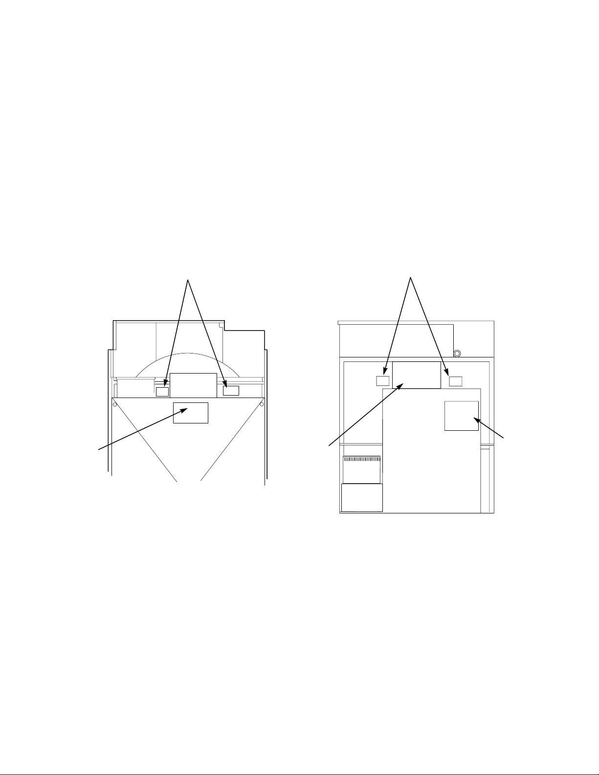
Serial Plate Location
When calling or writing about your product, be sure to
mention model and serial numbers. Model and serial
numbers are located on serial plate as shown.
Introduction
Junction
Box
Cover
Serial
Plate
120 Pound Models
TMB1497S
TMB1497S
Junction
Box
Cover
Serial
Plate
Wiring
Diagram
TMB1499S
170 Pound Models
70410601 5
© Copyright, Alliance Laundry Systems LLC – DO NOT COPY or TRANSMIT
Page 8

Introduction
Safety Warnings and Decals
SAFETY WARNINGS and decals have been provided
in key locations to remind you of important precautions
for the safe operation and maintenance of your tumbler.
Please take the time to review these warnings before
proceeding with service work.
All decals have been designed and applied to withstand
washing and cleaning. Decals should be checked
periodically to be sure they have not been damaged,
removed, or painted. Refer to the Parts Manual for
ordering replacement decals.
Safety Precautions for Servicing Tumblers
• Disconnect electrical service.
• Shut off supply gas valve before servicing gas
components.
• Access panel MUST be reinstalled after
inspection or servicing of tumbler is completed.
• Use a non-corrosive leak detecting compound to
check all pipe connections for gas leaks. DO NOT
USE AN OPEN FLAME TO CHECK FOR GAS
LEAKS!
• Belt guard MUST be reinstalled after inspection
or servicing of tumbler is completed.
• Contactor box cover MUST be reinstalled after
inspection or servicing of electric and/or reversing
tumbler is completed.
• Loading door switch MUST be operational before
putting tumbler into service.
• Junction box cover MUST be reinstalled after
inspection or servicing of tumbler is completed.
6 70410601
© Copyright, Alliance Laundry Systems LLC – DO NOT COPY or TRANSMIT
Page 9

Section 3
Troubleshooting
WARNING
To reduce the risk of electric shock, fire, explosion, serious injury or death:
• Disconnect electric power to the tumbler before servicing.
• Close gas shut-off valve to gas tumbler before servicing.
• Close steam valve to steam tumbler before servicing.
• Never start the tumbler with any guards/panels removed.
• Whenever ground wires are removed during servicing, these ground wires must be
reconnected to ensure that the tumbler is properly grounded.
IMPORTANT: Refer to wiring diagram for aid in testing tumbler components.
W002
70410601 7
© Copyright, Alliance Laundry Systems LLC – DO NOT COPY or TRANSMIT
Page 10
Troubleshooting
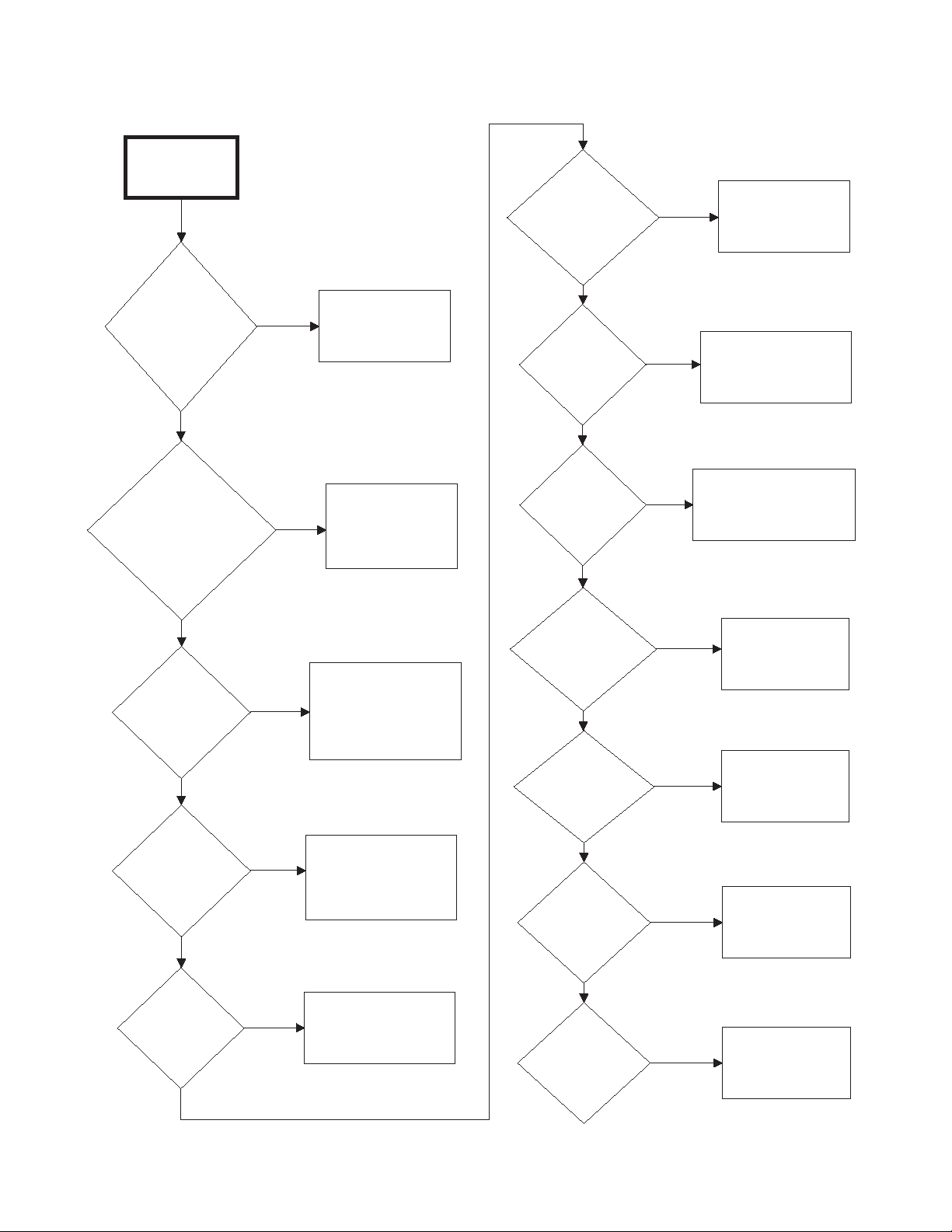
1. Motor Does Not Start
Motor Does
Not Start
Is there
broken, loose,
or incorrect
wiring?
Yes
Refer to wiring
diagram.
Is the
electrical power
off or circuit
breaker fuse
blown?
No
Is the
loading door
switch not
closed or switch
inoperative?
No
Is the
door switch
improperly
adjusted?
Yes
Yes
Check power
supply, or replace
Close door, panel
Yes
or test switch and
inoperative.
Refer to
Installation
Manual
switch adjustment.
fuses.
replace if
for door
No
Is the
transformer
inoperative?
No
Is the
motor relay
inoperative?
No
Are
trunnion
bearings
binding?
No
Yes
Yes
Yes
Test and replace
if necessary.
Test relay and replace
if inoperative.
Replace
trunnion
bearings.
Are
No
Is the start
circuit not
complete?
No
Is the motor
inoperative?
No
8 70410601
Yes
Yes
© Copyright, Alliance Laundry Systems LLC – DO NOT COPY or TRANSMIT
Press start switch
or test switch
and replace if
inoperative.
Have motor tested
and replace if
inoperative.
idler bearings
binding?
No
Is timer
improperly
set?
No
Is timer
inoperative?
Yes
Yes
Yes
Replace
bearings.
Turn drying timer
clockwise to
desired setting.
Test timer and
replace if
inoperative.
TMB2115S
Page 11
2. Motor Overload Protector Cycles Repeatedly
Motor Overload
Protector
Cycles
Repeatedly
Is voltage
correct?
No
Yes
Installation
Manual
requirements.
Troubleshooting
Refer to
for
electrical
Is clothes
load too
large?
No
Is clothes
cylinder
binding?
No
Is wiring
adequate?
No
Is make-up
air adequate?
Yes
Yes
Yes
Yes
Remove part of
load.
Check cylinder
for binding.
Check with
local power
company to
ensure that
wiring is
adequate.
Refer to
Installation
Manual
make-up air
requirements.
for
No
Clean lint
Is there lint
buildup around
tumbler or poor
maintenance?
No
70410601 9
© Copyright, Alliance Laundry Systems LLC – DO NOT COPY or TRANSMIT
Yes
Is there
broken, loose
or incorrect
wiring?
accumulation
on and around
the motors.
Yes
Refer to wiring
diagram.
TMB1904S
Page 12

Troubleshooting
3. Motor Runs But Cylinder Does Not Turn
Motor Runs
But Cylinder
Does Not Turn
Is cylinder
belt broken
or loose?
No
Is cylinder
binding?
No
Is motor
drive pulley
loose?
No
Yes
Yes
Yes
Replace or
adjust cylinder
belt.
Check cylinder
for binding.
Tighten drive
pulley bushing
screws.
Is drive belt
broken or
loose?
10 70410601
© Copyright, Alliance Laundry Systems LLC – DO NOT COPY or TRANSMIT
Yes
Replace or
adjust drive
belt.
TMB2116S
Page 13

4. Motor Does Not Stop
Motor Does
Not Stop
Troubleshooting
Is the door
switch not
working
properly?
No
Is wiring
incorrect?
No
Is timer
inoperative?
Yes
Yes
Yes
Test switches and
replace if inoperative.
Refer to
Manual
switch adjustment.
Refer to wiring
Test timer and
inoperative.
Installation
for proper
diagram.
replace if
No
Is motor
contactor
inoperative?
70410601 11
© Copyright, Alliance Laundry Systems LLC – DO NOT COPY or TRANSMIT
Yes
Test motor
contactor and
replace if
inoperative.
TMB2117S
Page 14

Troubleshooting
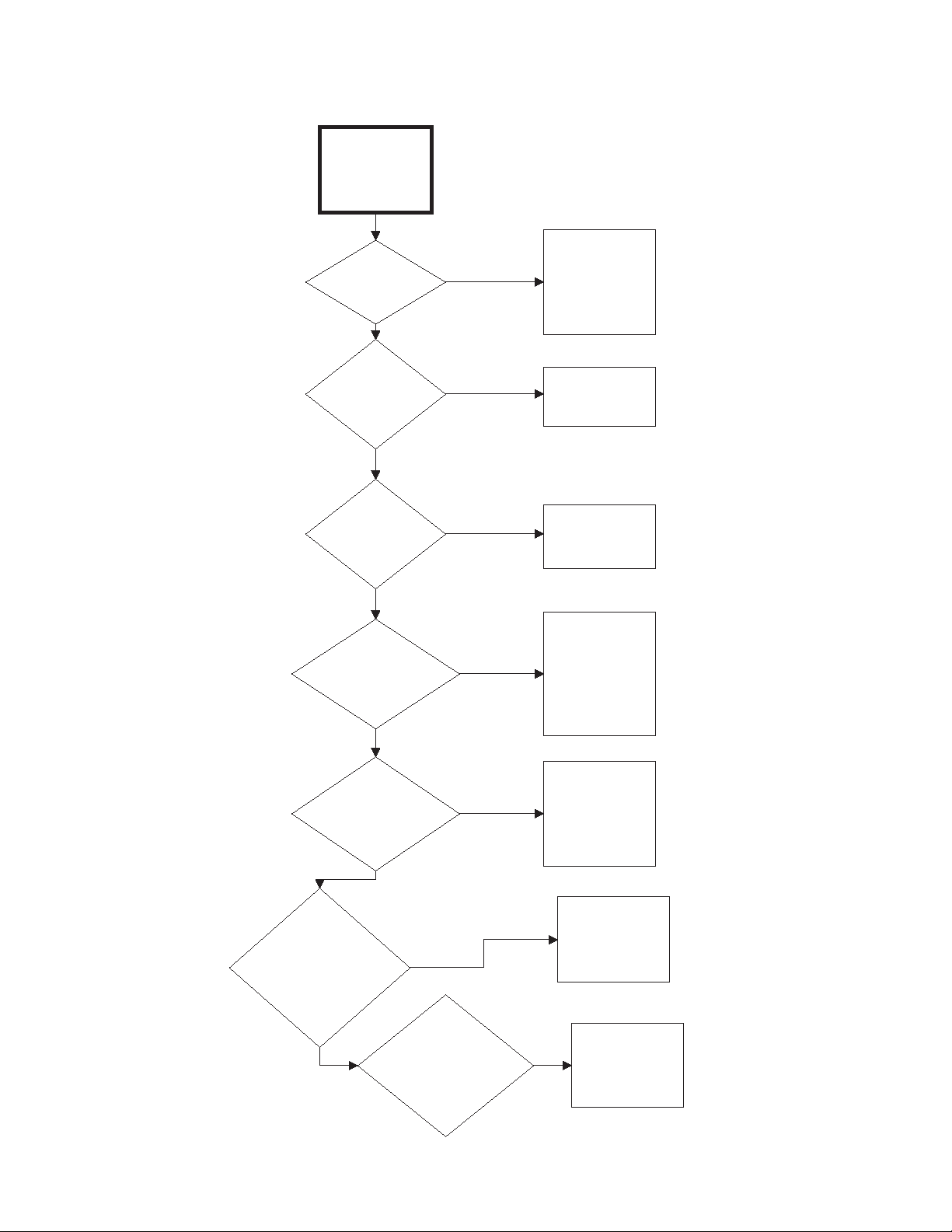
5. Gas Burner Does Not Ignite
Burner Does
Not Ignite
Is there
an improper or
inadequate exhaust
system?
Yes
Refer to
Installation
Manual
exhaust system
requirements.
for
Are the
orifices
incorrect?
No
Tumbler is equipped
for type of gas
Yes
specified on serial
plate. If orifices are
different from that
specified on serial
plate, obtain and
install correct orifices.
No
Are there
blown fuses or
tripped circuit breakers
in external electric
supply line?
No
Is
drying timer
not selected or
inoperative?
No
Is
thermostat
inoperative?
Yes
Yes
Yes
Check fuses or
circuit breaker.
Set drying timer
or replace if
inoperative.
Test thermostat
and replace if
inoperative.
Is there
lint
buildup?
No
Is there
inadequate
ductwork and
make-up
air?
No
Is the
airflow switch
inoperative?
Yes
Yes
Clean lint
compartment. Check
damper for lint
accumulation. Check
ductwork for lint
buildup.
Refer to
Installation
Manual
that ductwork and
make-up air
openings are sized
accurately.
Yes
Test switch
and replace
if inoperative.
to ensure
No
No
Is
there an
insufficient gas
supply?
No
12 70410601
Yes
Open partially closed gas
shut-off valve, or correct low
gas pressure. Check
manifold pressure and
adjust to pressure specified
on serial plate. If pressure
cannot be obtained, have
your local gas company
check main gas pressure.
© Copyright, Alliance Laundry Systems LLC – DO NOT COPY or TRANSMIT
Is airflow
switch out of
adjustment?
No
Yes
Refer to
Manual
switch adjustment.
Installation
for airflow
Continued on
next page
TMB2118S-a
Page 15

5. Gas Burner Does Not Ignite (continued)
Troubleshooting
Continued from
previous page
Is the lint
door panel
not closed
properly?
No
Is
there broken,
loose or incorrect
wiring?
No
Open lint door panel,
Ye s
place lint door and
panel back on
tumbler (ensuring a
tight fit).
Ye s
Refer to
wiring diagram.
Is fan rotation
improper?
Ye s
May be due to
improper wiring
resulting in low
air flow. Refer to
Installation
Manual.
Is
there an
inoperative
igniter?
No
Is the igniter
control
inoperative?
No
Are valve coils
inoperative?
Ye s
Ye s
Ye s
Te st igniter
and replace if
inoperative.
Te st igniter control
and replace if
inoperative.
Check valve coils
and replace if
necessary.
No
70410601 13
© Copyright, Alliance Laundry Systems LLC – DO NOT COPY or TRANSMIT
TMB2118S-b
Page 16

Troubleshooting
6. Burner Ignites and Goes Out Repeatedly
Burner Ignites and
Goes Out Repeatedly
Is there
insufficient
gas pressure?
No
Are the
burner ports
plugged?
No
Check gas supply
Yes
Yes
and pressure.
Low flame will
not maintain
sensor conductivity.
Check burner tubes
for build-up.
Does
tumbler have
improper
orifices?
No
Is
there inadequate
make-up air?
Tumbler is
equipped for type
of gas specified on
Yes
Yes
serial plate. If
orifices are different
from that specified
on serial plate,
obtain and install
correct orifices.
Installation Manual
for make-up air
requirements.
Refer to
Is high limit
or cabinet limit
thermostat
inoperative?
No
Is the
exhaust system
improper or
inadequate?
No
Yes
Yes
Test thermostat
and replace if
inoperative.
Refer to
Installation Manual
for exhaust system
equirements.
TMB2119S
14 70410601
© Copyright, Alliance Laundry Systems LLC – DO NOT COPY or TRANSMIT
Page 17

7. Burner Shuts OFF Prematurely
Burner shuts off
prematurely
Troubleshooting
Is there
improper or
inadequate
exhaust and/or
make-up air?
No
Is there
insufficient
gas supply?
No
Is tumbler
not properly
equipped for
type of gas
used?
No
Refer to
Installation Manual
Ye s
for exhaust and
make-up air
requirements.
Open partially
Ye s
closed gas shut-off
valve or correct low
pressure.
Tumbler is
equipped
for type of gas
specified on serial
Ye s
plate. If orifices are
different from that
specified on serial
plate, obtain and
install proper
orifices.
Is there
broken, loose
or incorrect
wiring?
No
Is there
Improper fan
rotation?
Ye s
wiring diagram
located inside
contactor box.
May be due to
improper wiring
Ye s
resulting in low
air flow. Refer
to Installation
Refer to
Manual.
Is burner
flame
improperly
adjusted?
Ye s
Refer to
Installation Manual
for burner flame
adjustment.
No
Is high limit
thermostat
cycling off?
Ye s
Refer to
Paragraph 8.
No
TMB2120S
70410601 15
© Copyright, Alliance Laundry Systems LLC – DO NOT COPY or TRANSMIT
Page 18

Troubleshooting
8. Burner Repeatedly Cycles Off on High Limit Thermostat
Burner repeatedly
cycles off on high
limit thermostat
Is external
exhaust system
longer than
recommended or is
there inadequate
make-up air?
No
Is lint screen
clogged?
No
Is there lint
in tumbler
ducts?
No
Is there lint
in external
exhaust
system?
Refer to
Yes
Installation
Manual
exhaust and
make-up air
requirements.
Remove screen
and clean. Lint
Yes
Yes
Yes
screen and
compartment
should be cleaned
after every eight
hour shift.
Clean tumbler
ducts.
Disassemble
exhaust
system and
clean.
for
Is high limit
thermostat
cycling at too
low a
temperature?
No
Is lint door
panel not
closed
properly?
No
Is there
improper fan
rotation?
Yes
Yes
Yes
Replace
thermostat.
Remove lint door
panel, place lint
door panel back on
tumbler (ensuring a
tight fit).
May be due to
improper wiring
resulting in low air
flow. Refer to
Installation
Manual.
3 Phase power:
reverse L1 and L2
incoming power,
check for proper
rotation.
No
16 70410601
© Copyright, Alliance Laundry Systems LLC – DO NOT COPY or TRANSMIT
TMB2122S
Page 19

9. Steam Valve or Burner Does Not Shut Off
Steam Valve or
Burner Does
Not Shut Off
Troubleshooting
Are there
impurities on gas
or steam valve
seat, preventing
valve from
closing?
No
Is wiring
correct?
No
Is drying timer
inoperative?
Yes
Yes
Yes
Replace gas
valve or
disassemble
and clean
steam valve.
Refer to wiring
diagram.
Replace
timer.
TMB2121S
70410601 17
© Copyright, Alliance Laundry Systems LLC – DO NOT COPY or TRANSMIT
Page 20

Troubleshooting
10. Clothes Do Not Dry
Clothes Do Not
Dry
Is there
enough heating
time allocated for
the load?
No
Is the
heat source
inoperative?
No
Is there
too much water in
articles being
dried?
Yes
Yes
Yes
Start cycle again
with enough time to
dry load.
Refer to
Flowchart 17
Remove excess
.
water.
Does heat
source shut off
prematurely?
No
Is
the drying
selector
improperly
set?
No
Is
the voltage
incorrect?
No
Yes
Yes
Yes
Refer to
Flowchart 17
Set selector
for higher
setting.
Refer to
Manual
Installation
for electrical
requirements.
.
No
Is
the clothes
load too
large?
No
Is the
exhaust system
improper or
inadequate?
No
Yes
Yes
Remove part of
load. Maximum
load is 120 pound
dry weight (cotton
load) for 120
pound Tumbler,
etc.
Refer to
Manual
system equirements.
Installation
for exhaust
Is there
inadequate
make-up
air?
No
Is there
improper fan
rotation?
Yes
Refer to
Manual
air requirements.
Yes
resulting in low air
Installation
for make-up
May be due to
improper wiring
flow. Refer to
Installation
Manual
.
TMB2123S
18 70410601
© Copyright, Alliance Laundry Systems LLC – DO NOT COPY or TRANSMIT
Page 21

11. Tumbler Overheating
Tumbler
Overheating
Troubleshooting
Gas Models:
Does tumbler
have incorrect main
burner orifices?
No
Gas Models:
Is gas pressure
too high or low?
No
Steam Models:
Is steam solenoid
valve stuck open.
Ye s
Ye s
Ye s
Obtain and install
correct orifices.
Adjust gas pressure
as specified on
serial plate.
Clean solenoid valve
and replace if
necessary.
Is the
exhaust system
restricted or
inadequate?
No
Is the
thermostat
inoperative?
Ye s
Ye s
Remove obstruction
or lint build up from
exhaust ductwork.
Refer to Installation
Manual for exhaust
system
requirements.
Replace
thermostat.
No
Is the
make-up air
inadequate?
Ye s
Refer to Installation
Manual for make-up
air requirements.
No
Clean lint
compartment. Check
Is there
lint buildup?
Ye s
damper for lint
accumulation. Check
ductwork for lint
buildup.
No
TMB2124S
70410601 19
© Copyright, Alliance Laundry Systems LLC – DO NOT COPY or TRANSMIT
Page 22

Troubleshooting
12. Burner Not Burning Properly
Burner Not Burning
Properly
Are burner air
shutters incorrectly
adjusted?
No
Is there lint/dirt
in burner tube?
No
Is the gas
pressure too high
or low?
No
Does
the tumbler have
incorrect
orifices?
No
Yes
Installation
Manual
flame adjustment.
Yes
Yes
Yes
Disassemble
burner and
blow out the dirt.
Check serial
plate on back of
tumbler for
correct gas
Tumbler is equipped
for the type of gas
specified on serial
plate. If orifices are
different from that
specified on serial
plate, obtain and
install correct
orifices.
Refer to
for proper
pressure.
Is
the airflow
switch not
functioning
properly?
No
Is there
inadequate
make-up
air?
No
Is there
improper fan
rotation?
Yes
Yes
Yes
Replace airflow
switch.
Refer to
Installation Manual
for make-up air
requirements.
May be due to
improper wiring
resulting in low air
flow. Refer to
Installation
Manual
.
Is the
exhaust duct
restricted or
blocked?
No
20 70410601
Yes
© Copyright, Alliance Laundry Systems LLC – DO NOT COPY or TRANSMIT
Disassemble
and clean
exhaust system.
TMB2125S
Page 23

13. Loading Door Opens During Operation
Loading Door
Opens During
Operation
Troubleshooting
Is tumbler
improperly
leveled?
No
Is clothes load
too large?
No
Is door strike
adjusted
incorrectly?
Yes
Yes
Yes
Refer to
Manual
Remove part of load
and restart tumbler.
Installation
for leveling
leg adjustment.
Refer to
Installation Manual
for strike
adjustment.
TMB2126S
70410601 21
© Copyright, Alliance Laundry Systems LLC – DO NOT COPY or TRANSMIT
Page 24

Troubleshooting
14. Tumbler Runs But No Steam to Coils – Steam Models
Tumbler runs but
no steam to
coils - Steam
Models
Are valves
closed?
No
Is steam trap
blocked?
No
Is solenoid valve
inoperative?
No
Yes
Yes
Yes
Check all valves in
supply and return
lines, make sure
they are open.
Remove trap and
clean. Replace if
inoperative.
Check operation
of solenoid valve.
Is check valve
incorrectly
installed?
No
Is strainer
clogged?
22 70410601
© Copyright, Alliance Laundry Systems LLC – DO NOT COPY or TRANSMIT
Yes
Yes
Check for inlet and
outlet markings on
check valve and
invert if necessary.
Remove strainer
and clean.
TMB2127S
Page 25

15. Water In Steam Line – Steam Models
Water in steam
line - Steam
Models
Troubleshooting
Is steam
piping
installed
incorrectly?
No
Is trap
functioning
improperly?
Yes
Yes
Refer to
Installation
Manual
requirements.
Check trap for size
and capacity. If trap is
dirty or sluggish clean
thoroughly or replace.
Check return line for
high back pressure.
for
steam
TMB1887S
70410601 23
© Copyright, Alliance Laundry Systems LLC – DO NOT COPY or TRANSMIT
Page 26

Troubleshooting
16. Tumbler Will Not Start, Time On Drying Timer, Door Closed
Tumbler Will Not Start,
Time On Drying Timer,
Door Closed
Is there
line voltage
into
transformer?
No
Check electrical
service to tumbler
(fuses/circuit breaker).
Is there 120
volts out of
door switch?
Yes
Yes
Is
there control
(120 VAC)
voltage out of
transformer?
No
Replace
transformer.
Is there
120 volts at
terminal 3 of
control relay?
Yes
Yes
Is there
blown
control circuit
fuse?
Yes
Replace
fuse.
Is there
120 volts
across coil
terminals of
control relay?
No
Yes
Is there 120
volts into
door switch?
No
Check for broken wire
between fuse and door
switch.
Is there
120 volts on
terminal 1 of
control relay?
Yes
Yes
No
Check for broken
Is
Yes
24 70410601
door switch
actuator
functioning
properly?
No
Adjust
actuator.
door switch.
© Copyright, Alliance Laundry Systems LLC – DO NOT COPY or TRANSMIT
wire or poor
connection at
harness plug.
Replace
No
120 volts on
terminal B of
drying timer?
No
Is there
No
Replace
timer.
No
Replace
relay.
Continued on
next page
TMB2128S-a
Page 27

Troubleshooting
16. Tumbler Will Not Start, Time On Drying Timer, Door Closed (continued)
Continued from
previous page
Is there
120 volts into
push-to-start
switch?
No
Check for broken
wire from control
relay terminal 1.
Yes
Press
push-to-start
switch. Is there
120 volts out of
push-to-start
switch?
No
Replace
push-to-start
switch.
Yes
Check for broken
wire or poor
connection at
harness plug.
Is there
120 volts
across fan
contactor
coil?
No
Yes
Replace fan
contactor.
TMB2128S-b
70410601 25
© Copyright, Alliance Laundry Systems LLC – DO NOT COPY or TRANSMIT
Page 28

Troubleshooting
17. Motor Runs But Will Not Heat
Motor Runs But
Will Not Heat
Is igniter
sparking?
Yes
Is green
wire from
IEI control
connected to
ground
terminal?
Yes
No
IEI control
in safety
lockout?
Open and
close door.
No
Connect green
wire to ground
Is
Yes
terminal.
No
Is
resistance of
high voltage
lead greater
than 28,000
ohms or less
than 10,500
ohms?
Yes
Replace high
voltage lead.
No
Is
igniter gap
not 5/32 inch
(.397 cm) or is
ceramic
cracked?
Yes
Regap or
replace igniter.
Replace
IEI control.
No
Is gas
shut-off
valve turned
on?
Yes
Is 120 volts
present on
black wire from
IEI control?
Yes
Is there an
open circuit
on gas valve
coil?
No
No
Yes
Turn on gas
shut-off valve.
Replace IEI
control.
Replace gas
valve.
TMB2129S
26 70410601
© Copyright, Alliance Laundry Systems LLC – DO NOT COPY or TRANSMIT
Page 29

18. Cylinder Turns, But Will Not Heat
Cylinder Turns,
But Will Not Heat
Troubleshooting
Is airflow
light
glowing?
No
Is gas
shut-off valve
open?
Yes
Is
120 volts
present at
output terminal
of main
thermostat?
Yes
No
Yes
Is fan turning
counter-clockwise
as viewed from
Open gas
shut-off valve.
Check for
broken or
loose wire to
ignition
control.
the front?
No
Yes
Reverse any two of the
electrical service leads at the
fan motor contactor.
Is
120 volts
present at
terminal 4
of relay?
No
Refer to
for makeup air and exhaust
duct requirements.
Yes
Installation Manual
Replace
relay.
Is
120 volts
present across
coil terminals
of relay?
Yes
Is
No
Is
120 volts
present at input
terminal of main
thermostat?
No
Is
120 volts
present at
terminal 6
of relay?
No
70410601 27
Yes
Replace main
thermostat.
Check for
Yes
© Copyright, Alliance Laundry Systems LLC – DO NOT COPY or TRANSMIT
broken or
loose wire to
main
thermostat.
120 volts
present at output
terminal of stove
high limit
thermostat?
No
Is
120 volts
present at input
terminal of stove
high limit
thermostat?
No
Yes
Replace stove
Yes
Continued on
next page
Check for
broken or loose
wire to relay.
high limit
thermostat.
TMB2130S-a
Page 30

Troubleshooting
18. Cylinder Turns, But Will Not Heat (continued)
Continued from
previous page
Is
120 volts
present on red
wire of fan
motor?
Is 120 volts
present at
output terminal of
airflow switch?
Check for broken
Yes
or loose wire to
stove high limit
thermostat.
No
Yes
Check for broken or
loose wire to
exhaust high limit
thermostat.
No
Is 120 volts
present at input
terminal of airflow
switch?
No
Is 120 volts
present at
output terminal of
exhaust high limit
thermostat?
No
Yes
Yes
Replace airflow
Check for broken
or loose wire to
airflow switch.
switch.
Is 120 volts
present on
brown wire of
fan motor?
No
Is
120 volts present
on output terminal
of fan contactor
aux contact?
No
Is
120 volts present
on input terminal
of fan contactor
aux contact?
Yes
Replace
fan motor.
Check for broken or
Yes
loose wire to fan
motor.
Yes
Replace fan
contactor.
Is 120 volts
present at input
terminal of exhaust
high limit
thermostat?
No
28 70410601
© Copyright, Alliance Laundry Systems LLC – DO NOT COPY or TRANSMIT
Replace exhaust
Yes
thermostat.
high limit
No
Check for broken or
loose jumper wire to
contactor contacts.
TMB2130S-b
Page 31

Section 4
Adjustments
WARNING
To reduce the risk of electric shock, fire, explosion, serious injury or death:
• Disconnect electric power to the tumbler before servicing.
• Close gas shut-off valve to gas tumbler before servicing.
• Close steam valve to steam tumbler before servicing.
• Never start the tumbler with any guards/panels removed.
• Whenever ground wires are removed during servicing, these ground wires must be
reconnected to ensure that the tumbler is properly grounded.
W002
19. Drive Belt Tension
Refer to Figure 1.
NOTE: If cylinder belts will be adjusted, service
them before drive belt.
NOTE: To find the proper tension, apply light
thumb pressure midway between the sheave and
motor pulley, and adjust until the belt can be
depressed approximately 1/2 inch (13 mm).
Side
Bracket
a. Support corner drive guard and remove screws
holding corner guard to rear of tumbler.
b. Support drive guard cover and remove screws
holding guard to rear of tumbler.
c. Reinstall drive guard.
d. Loosen the two side bracket attaching screws.
e. Turn the adjusting nuts clockwise until proper
tension is reached.
f. Tighten all nuts and screws.
Side
Bracket
Attaching
Screw
Motor
Mounting
Bracket
Adjusting
Nuts
Adjusting
Tube
T237P
T237P
Figure 1
70409601 29
© Copyright, Alliance Laundry Systems LLC – DO NOT COPY or TRANSMIT
Page 32

Adjustments
WARNING
To reduce the risk of electric shock, fire, explosion, serious injury or death:
• Disconnect electric power to the tumbler before servicing.
• Close gas shut-off valve to gas tumbler before servicing.
• Close steam valve to steam tumbler before servicing.
• Never start the tumbler with any guards/panels removed.
• Whenever ground wires are removed during servicing, these ground wires must be
reconnected to ensure that the tumbler is properly grounded.
W002
20. Cylinder Belt Tension
NOTE: To find the proper tension, apply light
thumb pressure midway between the cylinder
sheave and the step pulley, and adjust until the belt
can be depressed approximately 1/2 inch (13 mm).
a. Support corner drive guard and remove screws
holding corner guard to rear of tumbler.
b. Support drive guard cover and remove screws
holding guard to rear of tumbler.
c. Loosen the four jackshaft assembly attaching
screws. Refer to Figure 2.
d. Loosen adjusting nuts on outer eyebolt and
rotate bottom nut clockwise until proper
tension is reached. Refer to Figure 1.
e. Retighten all nuts and screws.
f. Readjust drive belt.
IMPORTANT: Adjusting the cylinder belt tension
WILL AFFECT the drive belt tension. You MUST
check and readjust the drive belt tension after
adjusting the cylinder belt tension.
Jackshaft
Assembly
Attaching
Screws
21. Fan Belt Tension
Refer to Figure 3.
NOTE: To find the proper tension, apply light
thumb pressure midway between the fan motor
pulley and the fan pulley, and adjust until the belt
can be depressed approximately 1/2 inch (13 mm).
a. Support corner drive guard and remove screws
holding corner guard to rear of tumbler.
b. Support drive guard cover and remove screws
holding guard to rear of tumbler.
c. Loosen the two mounting bracket attaching
screws.
d. Raise or lower eye bolt until proper tension is
reached.
e. Retighten all nuts and screws.
Fan
Belt
Fan
Motor
Pulley
Eye
Bolt
Mounting
Fan
Pulley
Jackshaft
Assembly
T317P
Figure 2
30 70409601
© Copyright, Alliance Laundry Systems LLC – DO NOT COPY or TRANSMIT
Figure 3
Bracket Attaching
Screws
T213SE1A
Page 33

WARNING
To reduce the risk of electric shock, fire, explosion, serious injury or death:
• Disconnect electric power to the tumbler before servicing.
• Close gas shut-off valve to gas tumbler before servicing.
• Close steam valve to steam tumbler before servicing.
• Never start the tumbler with any guards/panels removed.
• Whenever ground wires are removed during servicing, these ground wires must be
reconnected to ensure that the tumbler is properly grounded.
Adjustments
W002
22. Cylinder Clearance
The clearance between the cylinder rim and front
panel must be adjusted so the cylinder is centered
within the front panel opening when the cylinder
is fully loaded and is turning. However, the
adjustment should be made when the cylinder is
empty.
NOTE: If the cylinder is not properly adjusted, the
cylinder rim will rub against the front panel.
a. Open loading door.
b. Check the gap between the center of the front
panel top flange and the cylinder rim. Proper
adjustment is when the gap is 8/32 inch ± 3/32
inch. Refer to Figure 4. Perform steps “a”
through “g” to adjust the cylinder rim/front
panel flange clearance.
c. Check the cylinder fore/aft clearance between
the inside front of the cylinder and the edge of
the front panel flange. Proper adjustment is
when the gap is 9/32 inch ± 1/32 inch. Refer to
Figure 4. Perform steps “h” through “m” to
adjust the cylinder fore/aft clearance.
Cylinder Rim/Front Panel Flange
Clearance Adjustment
a. Support corner drive guard and remove screws
holding corner guard to rear of tumbler.
b. Support drive guard cover and remove screws
holding guard to rear of tumbler.
c. Loosen rear bearing mounting screws. Refer to
Figure 5.
d. Loosen the locknuts on rear adjustment screws.
Refer to Figure 5.
e. Turn the adjusting screws in or out as necessary
to obtain proper clearance between cylinder rim
and front panel.
f. After the cylinder is properly adjusted, tighten
the adjusting screw locknuts and the rear
bearing mounting screws.
g. Install drive guard cover.
NOTE: If adjusting the trunnion housing fails to
correct the clearance, the problem is probably due
to a worn trunnion shaft or defective bearings.
Cylinder Fore/Aft Clearance
Adjustment
h. Support corner drive guard and remove screws
holding corner guard to rear of tumbler.
i. Support drive guard cover and remove screws
holding guard to rear of tumbler.
j. Loosen setscrews in the front bearing assembly
collar and rear bearing assembly collar. Refer to
Figure 5.
k. Move cylinder assembly in or out as necessary
to obtain proper clearance between the cylinder
and the front panel.
l. After the cylinder is properly adjusted, tighten
setscrews in the front and rear bearing assembly
collars.
m. Install drive guard cover.
NOTE: Turning the adjusting screws clockwise will
raise the cylinder and turning them counterclockwise will lower the cylinder. Turn both screws
evenly to adjust top and bottom clearance. Turn one
or the other adjusting screw in or out to adjust side
clearance.
70409601 31
© Copyright, Alliance Laundry Systems LLC – DO NOT COPY or TRANSMIT
Page 34

Adjustments
Cylinder
Rim
9/32" ± 1/32"
Inside
Front of
Cylinder
8/32" ± 3/32"
Cylinder Rim /
Front Panel
Flange
Clearance
Rear
Bearing Mounting
Screw
Rear
Adjusting
Screw
Front
Panel Flange
(Top Shown)
Figure 4
Adjusting
Locknut
Fore / Aft
Clearance
T218S
Screw
TMB1500S
Front
Adjusting
Screw
Rear
Bearing Assembly
Front
Bearing Assembly
Collar
Collar
Figure 5
32 70409601
© Copyright, Alliance Laundry Systems LLC – DO NOT COPY or TRANSMIT
 Loading...