

Page 1
Preliminary Installation Information
Subject 200 Pound Tumble Dryer
Use With 70420801 Installation Manual
Model Identification
Gas Steam/Thermal Oil
200 Pound
DR200G2-BA200L
DR200G2-BA200N
DR200G2-BT200L
DR200G2-BT200N
DR200G2-BU200L
DR200G2-BU200N
CA200L
CA200N
CT200L
CT200N
CU200L
CU200N
HA200L
HA200N
HT200L
HT200N
HU200L
HU200N
IT200L
IT200N
SA200L
SA200N
ST200L
ST200N
SU200L
SU200N
UA200L
UA200N
UT200L
UT200N
UU200L
UU200N
DR200S2-BT200S
DR200S2-BT200T
DR200S2-BU200S
DR200S2-BU200T
CT200S
CT200T
CU200S
CU200T
HT200S
HT200T
HU200S
HU200T
IT200S
IT200T
ST200S
ST200T
SU200S
SU200T
UT200S
UT200T
UU200S
UU200T
Includes models with the following control suffixes:
R3 – reversing DX4 OPL RE – reversing OPL Micro RQ – reversing dual digital timer
RD – reversing DMP OPL RM – reversing OPL Micro RU – reversing UniLinc OPL
Page 1 of 12
© Copyright, Alliance Laundry Systems LLC – DO NOT COPY or TRANSMIT
Part No. 70470101
September 2011
Page 2
Specifications and Dimensions
Specifications 200 Pound
Noise level measured during operation at operator position of 3.3 feet
(1
meter) in front of machine and 5.2 feet (1.6 meters) from floor.
Cylinder Size: Inches (mm)
Cylinder Capacity dry weight: Pounds (kg)
Cylinder Motor Horsepower
66 dBA
50.75 x 50
(1289 x 1270)
200
(90.7)
0.75
Fan Motor Horsepower
Air Outlet Diameter: Inches (mm)
Maximum Static Back Pressure: W.C.I. (mbar)
Maximum Airflow: C.F.M (L/sec.)
Gas Models
Net Weight (approximate): Pounds (kg)
Gas Connection
Gas Burner Rating: Btu/hr. (Mj/hr.)
Steam Models
Net Weight (approximate): Pounds (kg)
Steam Connection
Steam Coil Rating at 100 psig:Boiler Horsepower (Btu/hr.)
(recommended operating pressure 80-100 psig)
3
12
(300)
0.3
(0.8)
2450
(1156)
1707
(774)
1 in. NPT
425,000
(448)
1807
(820)
3/4 in. NPT inlet
1 in. NPT outlet
18.8
(648,000)
Heating Element Rating:Kilowatts (kW)
N/A = Not Applicable
© Copyright, Alliance Laundry Systems LLC – DO NOT COPY or TRANSMIT
Electric Models
N/A
Page 2 of 12
Page 3
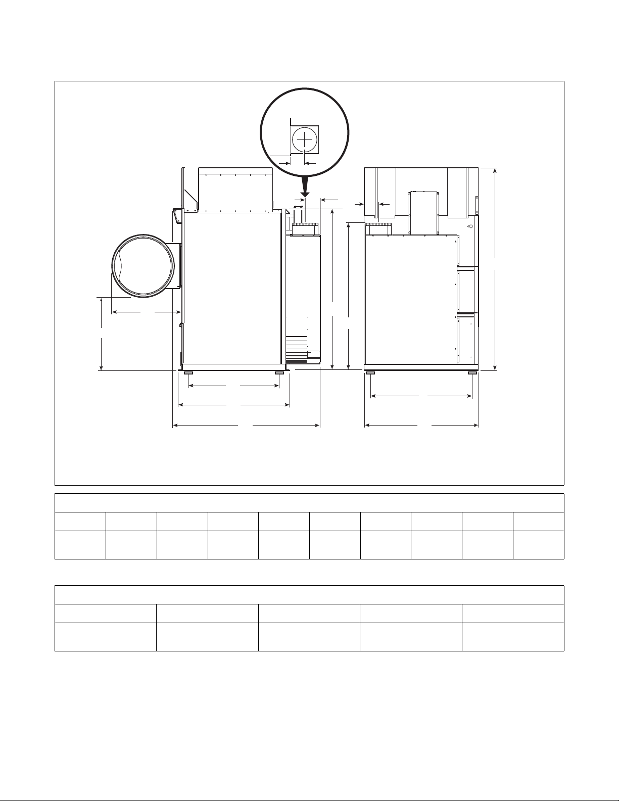
200 Pound Tumble Dryer
A
B
C
D
W
H
F
Y
X
V
TOP VIEW OF
EXHAUST
DUCT
E
G
I
Dimensions and Exhaust Outlet
Locations
Cabinet Dimensions
TMB2363N
Models A B C D E F G H I
200L/N/S
32.1 in.
(815 mm)
35.6 in.
(904 mm)
58 in.
(1473 mm)
59.25 in.
(1505 mm)
76.18 in.
(1935 mm)
52.12 in.
(1324 mm)
53.12 in.
(1349 mm)
94 in.
(2388 mm)
Refer to Position and Level the Tumble Dryer to temporarily reduce the heights of these models.
Exhaust Outlet Dimensions and Locations
Models V W X Y
200L/N/S
67.19 in.
(1707 mm)
© Copyright, Alliance Laundry Systems LLC – DO NOT COPY or TRANSMIT
7.03 in.
(179 mm)
Page 3 of 12
(229 mm)
9 in.
TMB2363N
75.12 in.
(1908 mm)
7 in.
(178 mm)
Page 4
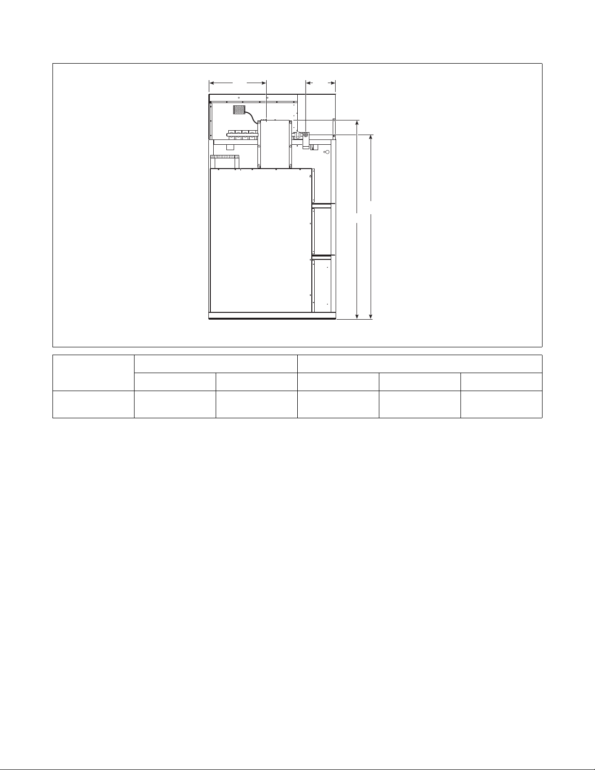
Electric and Gas Connection
C
A
B
D
Locations for Gas Models
Models
Electrical Connection Gas Connection
A B C D Diameter
200L/N
21 in.
(533 mm)
81 in.
(2057 mm)
NOTE: These figures are approximate dimensions only.
13.7 in.
(348 mm)
77.4 in.
(1966 mm)
TMB2357N
1 in. NPT
Page 4 of 12
© Copyright, Alliance Laundry Systems LLC – DO NOT COPY or TRANSMIT
Page 5

Electric and Steam Connection
A1
B1
B2
A2
D
E
F
C
Locations for Steam Models
Models
200S
Models
200S
Models
200S
Steam Inlet
Diameter A1 A2 F
3/4 in. NPT 37.625 in.
(956 mm)
15.25 in.
(387 mm)
88 in.
(2235 mm)
Steam Outlet
Diameter B1 B2 D
1 in. NPT 44.625 in.
(1133 mm)
Electrical Connection
8.75 in.
(222 mm)
71.75 in.
(1822 mm)
C E
21 in.
(533 mm)
81 in.
(2057 mm)
TMB2358N
Page 5 of 12
© Copyright, Alliance Laundry Systems LLC – DO NOT COPY or TRANSMIT
Page 6

Position and Level the Tumble Dryer
The tumble dryer may be moved with or without the
skid. To remove the skid, unscrew the four shipping
bolts, and discard them.
To fit a 200 pound tumble dryer (with shipping skid)
through an 8 foot (2.43 meters) high door, you must
remove the front access panel. The upper 3 inches
(76
mm) of the stove must also be removed on
200
pound gas tumble dryers. Removing the entire gas
or steam heater assembly and the shipping skid will
reduce the height to 75
inches (1905 mm).
Level the tumble dryer to within 0.125 inch (3 mm)
from front-to-rear (level on cylinder rib), and side-toside (level on top panel). Shim under corners to level
and stabilize unit. Tumble dryer must not rock.
Make-Up Air
Required Make-Up Air Opening
(to the outside) for Each Tumble Dryer
Models Opening
200 Pound
525 in.2 (3710 cm2)
free air
Table 1
Page 6 of 12
© Copyright, Alliance Laundry Systems LLC – DO NOT COPY or TRANSMIT
Page 7

Exhaust Requirements
LKJ I HG F
E
D
C
BA
3
1
2
ONE MANIFOLD ASSEMBLY
1 NOTE: Where the exhaust duct pierces a
combustible wall or ceiling, the opening
MUST be sized per local codes.
TMB2019N
2 Outlet Duct Diameter
3 45° Typical
Duct
Stations
A
B
C
D
E
F
G
H
I
J
K
L
Figure 1
12 in. (305 mm) Duct
Table 2
200 Pound
12 in. (305 mm)
17 in. (432 mm)
21 in. (533 mm)
24 in. (610 mm)
27 in. (686 mm)
30 in. (762 mm)
32 in. (813 mm)
34 in. (864 mm)
36 in. (914 mm)
38 in. (965 mm)
40 in. (1016 mm)
42 in. (1067 mm)
Page 7 of 12
© Copyright, Alliance Laundry Systems LLC – DO NOT COPY or TRANSMIT
Page 8

1 NOTE: Where the exhaust duct pierces a
1
2
3
L
K
J
I
L
K
J
I
CONTINUE
TO A
CONTINUE
TO A
TWO MANIFOLD ASSEMBLIES
combustible wall or ceiling, the opening
MUST be sized per local codes.
TMB2018N
2 Outlet Duct Diameter
3 45° Typical
Figure 2
Duct
Stations
A
B
C
D
E
F
G
H
I
J
K
L
200 Pound
12 in. (305 mm) Duct
17 in. (432 mm)
24 in. (610 mm)
30 in. (762 mm)
34 in. (864 mm)
38 in. (965 mm)
42 in. (1067 mm)
45 in. (1143 mm)
45 in. (1143 mm)
52 in. (1321 mm)
54 in. (1372 mm)
57 in. (1448 mm)
60 in. (1524 mm)
Table 3
Page 8 of 12
© Copyright, Alliance Laundry Systems LLC – DO NOT COPY or TRANSMIT
Page 9

Gas Requirements
For converting Non-CE Models from Natural Gas to
L.P. Gas:
200 Pound Models - M4975P3
High Altitude Orifice Sizing
For proper operation at altitudes above 2000 feet (610
meters), the gas orifice size must be reduced to ensure
complete combustion. Refer to
For CE models, consult local gas supplier.
Table 4.
Non-CE Models
Model Gas
2001 – 4000 610 – 1220 19 .1660 4.2
Natural
Gas
200L/N
L.P.
Gas
* Btu/hr. derate of 4% per 1000 ft. (305 m) of altitude.
4001 – 6000 1221 – 1830 20 .1610 4.1 M401002 357,000
6001 – 8000 1831 – 2440 22 .1570 4.0 M402996 323,000
8001 – 10,000 2441 – 3050 24 .1520 3.9 M402980 289,000
2001 – 4000 610 – 1220 33 .1130 2.9
4001 – 6000 1221 – 1830 34 .1110 2.8 M411512 357,000
6001 – 8000 1831 – 2440 7/64 .1094 2.8 70070902 323,000
8001 – 10,000 2441 – 3050 37 .1040 2.6 M401024 289,000
Altitude Orifice
feet m No. inches mm Quantity Part No. (Btu/hr.)*
New
Rate
M402995 391,000
5
M401022 391,000
4
Table 4
Page 9 of 12
© Copyright, Alliance Laundry Systems LLC – DO NOT COPY or TRANSMIT
Page 10

Electrical Requirements
For 200 Pound Tumble Dryer Models
Serial Plate Rating
200-208V/60Hz/3ph
240V/60Hz/3ph
380V/50 or 60Hz/3ph
400-415V/50Hz/3ph
440V/60Hz/3ph
460-480V/60Hz/3ph
L1, L2, L3 and ground 14 20A - 3 pole
L1, L2, L3 and ground 14 20A - 3 pole
L1, L2, L3 and ground 8 15A - 3 pole
L1, L2, L3 and ground 8 15A - 3 pole
L1, L2, L3 and ground 7 15A - 3 pole
L1, L2, L3 and ground 7 15A - 3 pole
Terminal Block
Connections Required
* Current ratings vary slightly depending on model; refer to serial plate.
Table 5
Rated
Current*
Breaker
Rating
Recommended Wire
Size
12 AWG (3.31 mm2)
12 AWG (3.31 mm2)
14 AWG (2.08 mm2)
14 AWG (2.08 mm2)
14 AWG (2.08 mm2)
14 AWG (2.08 mm2)
Page 10 of 12
© Copyright, Alliance Laundry Systems LLC – DO NOT COPY or TRANSMIT
Page 11

Steam Requirements
TMB2024N
SUPPLY
2
1
9
3
RETURN
2
3
7
10
4
5
8
6
NOTE: Refer to Table 6 for sizing of steam lines. Piping must also be sized accordingly for length of runs and number
of elbows.
1
2
3
4
5
Risers 12 in. (305 mm)
Shut-Off Valve
Check Valve
Vacuum Breaker (optional)
Condensate Return Line from Supply Line
6
7
8
9
10
18 in. Drop (457 mm)
Steam Bonnet
Solenoid Valve (Supplied with machine)
Union
Trap with Built-In Strainer
Figure 3
Model
200S
Steam Pressure
PSI (bar)
80-100 (5.3-6.9) 1-1/4 in. NPT 517
Minimum
Supply Pipe Diameter
Steam Trap Size *
(Pounds Condensate/Hour)
* Based on maximum psi.
Table 6
Page 11 of 12
TMB2024N
© Copyright, Alliance Laundry Systems LLC – DO NOT COPY or TRANSMIT
Page 12

Loading Door Strike
1
2
Belt Drive
The loading door strike must be adjusted to have
sufficient tension to hold loading door closed against
force of load tumbling against it. Proper adjustment is
when 8-15 pounds (35.6-66.7 N) pull is required to
open door.
If adjustment is required, refer to Figure 4 and proceed
as follows:
To adjust, open door, loosen adjustment screws and
position strike for desired magnet engagement.
retighten screws.
NOTE: Proper tensions for new belts are
45-55
pounds for the motor belt, 55-65 pounds for
the final drive and 65-70 pounds for 200 pound
blower, measured with a Borroughs Belt Tension
Gauge. Using a Browning Belt Tension Gauge, the
motor belt deflection should be 0.31
inch at five
pounds pressure, and final drive belt deflection
should be 0.25
inch at five pounds pressure.
TMB2359N
1 Door Strike
2 Adjustment Screws
Figure 4
Page 12 of 12
© Copyright, Alliance Laundry Systems LLC – DO NOT COPY or TRANSMIT
 Loading...