

Page 1

Drying Tumblers
30 Pound Capacity (28" Wide)
30 Pound Capacity (31.5" Wide)
Refer to Page 7 for Model Numbers
Installation/Operation/Maintenance
NOTA: El manual en
español aparace después
del manual en inglés.
KEEP THESE INSTRUCTIONS FOR FUTURE REFERENCE.
(If this tumbler changes ownership, be sure this manual accompanies
the tumbler.)
www.comlaundry.com
Part No. M414545
September 2002
Page 2

Page 3

TABLE OF CONTENTS
SECTION I
Safety
Important Safety Instructions . . . . . . . . . . . . . . . . . . 5
SECTION II
Introduction
Information for Handy Reference . . . . . . . . . . . . . . 7
Parts Ordering Information . . . . . . . . . . . . . . . . . . . 8
Nameplate Location . . . . . . . . . . . . . . . . . . . . . . . . . 8
Roughing-In Dimensions and Specifications
Cabinet Dimensions . . . . . . . . . . . . . . . . . . . . . . . . . 9
Roughing-In Dimensions and Specifications
Exhaust Thimble Locations . . . . . . . . . . . . . . . . . . . 10
Roughing-In Dimensions and Specifications
Steam Connection Locations . . . . . . . . . . . . . . . . . . 11
Roughing-In Dimensions and Specifications
Gas Connection Locations . . . . . . . . . . . . . . . . . . . . 12
Roughing-In Dimensions and Specifications
Electrical Connection Locations . . . . . . . . . . . . . . . 13
28" wide Gas Tumbler . . . . . . . . . . . . . . . . . . . . . . . 14
28" wide Electric Tumbler . . . . . . . . . . . . . . . . . . . . 14
Gas Tumbler . . . . . . . . . . . . . . . . . . . . . . . . . . . . . . . 15
Electric Tumbler . . . . . . . . . . . . . . . . . . . . . . . . . . . . 15
Example of Gas Supply Piping . . . . . . . . . . . . . . . . . 26
Steam Requirements (Steam Drying Tumblers) . . . . 28
Piping Recommendations . . . . . . . . . . . . . . . . . . 28
Steam Valve Electrical Connections . . . . . . . . . . 28
Installing Steam Solenoid Valve
and Making Steam Inlet Connections . . . . . . . . 29
Installing Steam Trap and Making Condensate
Return Connections . . . . . . . . . . . . . . . . . . . . . . 29
Steam Requirements
Steam Drying Tumblers Only . . . . . . . . . . . . . . . . . . 30
Electrical Requirements . . . . . . . . . . . . . . . . . . . . . . 31
Grounding Instructions . . . . . . . . . . . . . . . . . . . . 31
Jumper Configuration Instructions
(OPL Micro Control Models Only) . . . . . . . . . . 33
Ring Ferrite Installation
(Gas and Steam OPL Micro Control
Models Only) . . . . . . . . . . . . . . . . . . . . . . . . . . . 33
Electrical Requirements
For 28" wide Tumblers . . . . . . . . . . . . . . . . . . . . . . . 34
Electrical Requirements
For 31.5" wide Tumblers . . . . . . . . . . . . . . . . . . . . . 35
Accessory Timing Cam Installation
(Coin Meter Models) . . . . . . . . . . . . . . . . . . . . . . . . 36
Steam Tumbler . . . . . . . . . . . . . . . . . . . . . . . . . . . . . 15
SECTION III
Installation Instructions
Receiving Inspection . . . . . . . . . . . . . . . . . . . . . . . . 17
Materials Required (Obtain Locally) . . . . . . . . . . . . 17
Gas, Electric or Steam Drying Tumblers . . . . . . 17
Gas Drying Tumblers Only . . . . . . . . . . . . . . . . 17
Steam Drying Tumblers Only . . . . . . . . . . . . . . 17
Positioning the Tumbler . . . . . . . . . . . . . . . . . . . . . . 18
Leveling the Tumbler . . . . . . . . . . . . . . . . . . . . . . . . 18
Tumbler Enclosure Construction . . . . . . . . . . . . . . . 19
Facilities Required . . . . . . . . . . . . . . . . . . . . . . . . . . 20
Floor . . . . . . . . . . . . . . . . . . . . . . . . . . . . . . . . . . 20
Layout . . . . . . . . . . . . . . . . . . . . . . . . . . . . . . . . 20
Venting . . . . . . . . . . . . . . . . . . . . . . . . . . . . . . . . 20
Make-Up Air . . . . . . . . . . . . . . . . . . . . . . . . . . . 21
Gas Requirements . . . . . . . . . . . . . . . . . . . . . . . . . . 24
Example of Gas Loop Piping . . . . . . . . . . . . . . . . . . 26
Removal of Existing Timing Cam . . . . . . . . . . . 36
Installation of New Timing Cam . . . . . . . . . . . . 36
Preliminary Operating Checks . . . . . . . . . . . . . . . . . 37
Final Operating Checks . . . . . . . . . . . . . . . . . . . . . . 38
OPL Micro Control Tumbler . . . . . . . . . . . . . . . 38
Manual Dual Timer Tumbler . . . . . . . . . . . . . . . 38
Coin-Operated Tumbler . . . . . . . . . . . . . . . . . . . 38
SECTION IV
Adjustments
Main Gas Burner Air Shutter
All Gas Models . . . . . . . . . . . . . . . . . . . . . . . . . . . . . 41
Airflow Switch
For Gas and Electric Tumblers . . . . . . . . . . . . . . . . . 42
Loading Door Switch . . . . . . . . . . . . . . . . . . . . . . . . 43
Loading Door Strike . . . . . . . . . . . . . . . . . . . . . . . . . 44
Chain Drive Nonreversing Models . . . . . . . . . . . . . . 45
Belt Drive Nonreversing Models . . . . . . . . . . . . . . . 45
Belt Drive Reversing Models . . . . . . . . . . . . . . . . . . 46
M414545
© Copyright, Alliance Laundry Systems LLC – DO NOT COPY or TRANSMIT
1
Page 4

SECTION V
Operating Instructions
SECTION VI
Preventive Maintenance Instructions
Manual Dual Timer Tumbler . . . . . . . . . . . . . . . . . . 51
Coin-Operated Tumbler . . . . . . . . . . . . . . . . . . . . . . 52
Reversing Operation . . . . . . . . . . . . . . . . . . . . . . 53
Reverse Control Switch . . . . . . . . . . . . . . . . . . . 53
Electronically Controlled OPL Tumbler . . . . . . . . . . 54
Introduction . . . . . . . . . . . . . . . . . . . . . . . . . . . . 54
Status Lights, Signal and Reversing . . . . . . . . . . 56
Drying Laundry . . . . . . . . . . . . . . . . . . . . . . . . . 56
Security Lock-Out . . . . . . . . . . . . . . . . . . . . . . . 60
Temperature Adjustment . . . . . . . . . . . . . . . . . . 60
Show Mode . . . . . . . . . . . . . . . . . . . . . . . . . . . . 60
Temperature Sensor . . . . . . . . . . . . . . . . . . . . . . 60
Daily . . . . . . . . . . . . . . . . . . . . . . . . . . . . . . . . . . . . .65
Lint Removal . . . . . . . . . . . . . . . . . . . . . . . . . . . .65
Monthly . . . . . . . . . . . . . . . . . . . . . . . . . . . . . . . . . . . 66
Lubrication . . . . . . . . . . . . . . . . . . . . . . . . . . . . . 66
Lint Removal . . . . . . . . . . . . . . . . . . . . . . . . . . . .66
Every Three Months . . . . . . . . . . . . . . . . . . . . . . . . .66
Lint Removal . . . . . . . . . . . . . . . . . . . . . . . . . . . .66
Belt Tension . . . . . . . . . . . . . . . . . . . . . . . . . . . .66
Every Six Months . . . . . . . . . . . . . . . . . . . . . . . . . . .66
Overall Check . . . . . . . . . . . . . . . . . . . . . . . . . . .66
Energy Saving Tips . . . . . . . . . . . . . . . . . . . . . . . . . . 68
Service Savers . . . . . . . . . . . . . . . . . . . . . . . . . . . . . . 68
Troubleshooting the Tumbler . . . . . . . . . . . . . . . . . .69
©Copyright 2002, Alliance Laundry Systems LLC
All rights reserved. No part of the contents of this book may be reproduced or transmitted in any form or by any means
without the expressed written consent of the publisher.
2 M414545
© Copyright, Alliance Laundry Systems LLC – DO NOT COPY or TRANSMIT
Page 5
Section I
Safety
IMPORTANT: Warranty is void unless drying tumbler is installed according to instructions in this manual.
Compliance with minimum specifications and requirements detailed herein, and with applicable local gas fitting
regulations, municipal building codes, water supply regulations, electrical wiring regulations, and any other
relevant statutory regulations. Because of varied requirements, applicable local codes should be thoroughly
understood and all pre-installation work arranged for accordingly.
In the U.S.A., installation must conform to the latest edition of the American National Standard Z223.1 “National
Fuel Gas Code” and Standard ANSI/NFPA 70 “National Electric Code”.
In Canada, installation must comply with Standards CAN1-B149.1 or CAN1-B149.2 codes for gas burning
appliances and equipment and CSA C22.1, latest edition, Canadian Electric Code, Part I.
In Australia, installation must comply with the Australian Gas Association Installation Code for Gas Burning
Appliances and Equipment.
WARNING
Failure to install, maintain, and/or operate this machine according to manufacturer’s
instructions may result in conditions which can produce serious injury, death and/or
property damage.
NOTE: The WARNING and IMPORTANT instructions appearing in this manual are not meant to cover all
possible conditions and situations that may occur. It must be understood that common sense, caution and
carefulness are factors which CANNOT be built into this tumbler. These factors MUST BE supplied by the
person(s) installing, maintaining or operating the tumbler.
W051
Always contact your dealer, distributor, service agent or the manufacturer on any problems or conditions you do
not understand.
M414545
© Copyright, Alliance Laundry Systems LLC – DO NOT COPY or TRANSMIT
3
Page 6
IMPORTANT: Information must be obtained from your local gas supplier on instructions to be followed if the
user smells gas. These instructions must posted in a prominent location. Step-by-step instructions of the safety
information below must be posted in a prominent location near the tumbler for customer use.
WARNING
FOR YOUR SAFETY, the information in
this manual must be followed to minimize
the risk of fire or explosion or to prevent
property damage, personal injury or
death.
W033
• Do not store or use gasoline or other
flammable vapors and liquids in the vicinity
of this or any other appliance.
• WHAT TO DO IF YOU SMELL GAS:
– Do not try to light any appliance.
– Do not touch any electrical switch; do not
use any phone in your building.
– Clear the room, building or area of all
occupants.
– Immediately call your gas supplier from a
neighbor’s phone. Follow the gas
supplier’s instructions.
– If you cannot reach your gas supplier,
call the fire department.
• Installation and service must be performed
by a qualified installer, service agency or
the gas supplier.
W052
FOR YOUR SAFETY
Do not store or use gasoline or other
flammable vapors and liquids in the
vicinity of this or any other appliance.
W053
AVERTISSEMENT
POUR VOTRE SÉCURITÉ il est
impératif de suivre les instructions de
ce manuel pour minimiser les risques
d’incendie ou d’explosion et pour
éviter les dommages matériels, les
blessures corporelles ou la mort.
W033Q
• Ne pas entreposer ni utiliser d’essence ni
d’autres vapeurs ou liquides inflammables
dans le voisinage de cet appareil ou de
tout autre appareil.
• QUE FAIRE SI VOUS SENTEZ UNE ODEUR
DE GAZ :
– Ne pas tenter d’allumer d’apareil.
– Ne touchez à aucun interrupteur. Ne pas
vous servir des téléphones se trouvant
dans le bâtiment où vous vous trouvez.
–Évacuez la pièce, le bâtiment ou la zone.
– Appelez immédiatement votre
fournisseur de gaz depuis un voisin.
Suivez les instructions du fournisseur.
– Si vous ne pouvez rejoindre le
fournisseur de gaz, appelez le service
des incendies.
• L’installation et l’entretien doivent être
assurés par un installateur ou un service
d’entretien qualifié ou par le fournisseur
de gaz.
W052Q
POUR VOTRE SÉCURITÉ
Ne pas entreposer ni utiliser d’essence
ni d’autres vapeurs ou liquides
inflammables dans le voisinage de cet
appareil ou de tout autre appareil.
W053Q
4 M414545
© Copyright, Alliance Laundry Systems LLC – DO NOT COPY or TRANSMIT
Page 7

IMPORTANT SAFETY INSTRUCTIONS
(SAVE THESE INSTRUCTIONS)
WARNING
To reduce the risk of fire, electric shock, serious injury or death to persons when using
your tumbler, follow these basic precautions:
1. Read all instructions before using the tumbler.
2. Refer to the GROUNDING INSTRUCTIONS for the proper grounding of the tumbler.
3. Do not dry articles that have been previously cleaned in, washed in, soaked in, or spotted with gasoline, drycleaning solvents, other flammable or explosive substances as they give off vapors that could ignite or explode.
4. Do not allow children to play on or in the tumbler. Close supervision of children is necessary when the tumbler is
used near children. This is a safety rule for all appliances.
5. Before the tumbler is removed from service or discarded, remove the door to the drying compartment.
6. Do not reach into the tumbler if the cylinder is revolving.
7. Do not install or store the tumbler where it will be exposed to water and/or weather.
W054
8. Do not tamper with the controls.
9. Do not repair or replace any part of the tumbler, or attempt any servicing unless specifically recommended in the
User-Maintenance instructions or in published user-repair instructions that you understand and have the skills to
carry out.
10. Do not use fabric softeners or products to eliminate static unless recommended by the manufacturer of the fabric
softener or product.
11. To reduce the risk of fire, DO NOT DRY plastics or articles containing foam rubber or similarly textured
rubberlike materials.
12. Always clean the lint filter before every load. A layer of lint in the filter reduces drying efficiency and prolongs
drying time.
13. Keep area around the exhaust opening and adjacent surrounding area free from the accumulation of lint, dust and
dirt.
14. The interior of the tumbler and the exhaust duct should be cleaned periodically by qualified service personnel.
15. If not installed, operated and maintained in accordance with the manufacturer’s instructions or if there is damage to
or mishandling of this product’s components, use of this product could expose you to substances in the fuel or from
fuel combustion which can cause death or serious illness and which are known to the State of California to cause
cancer, birth defects or other reproductive harm.
16. Tumbler will not operate with the loading door open. DO NOT bypass the door safety switch by permitting the
tumbler to operate with the door open. The tumbler will stop tumbling when the door is opened. Do not use the
tumbler if it does not stop tumbling when the door is opened or starts tumbling without pressing or turning the
START mechanism. Remove the tumbler from use and call the serviceman. Tumbler will not operate with lint
panel open. DO NOT bypass lint panel safety switch by permitting the tumbler to operate with the lint panel open.
M414545
© Copyright, Alliance Laundry Systems LLC – DO NOT COPY or TRANSMIT
5
Page 8
17. Do not put articles soiled with vegetable or cooking oil in the tumbler, as these oils may not be removed during
drying. Due to the remaining oil, the fabric may catch on fire by itself.
18. To reduce the risk of fire, DO NOT put clothes which have traces of any flammable substances such as machine
oil, flammable chemicals, thinner, etc. or anything containing wax or chemicals such as in mops and cleaning
cloths, or anything dry-cleaned at home with a dry-cleaning solvent in the tumbler.
19. Use the tumbler only for its intended purpose, drying fabrics.
20. ALWAYS disconnect the electrical power to the tumbler before servicing. Disconnect power by shutting off
appropriate breaker or fuse.
21. Install this tumbler according to these INSTALLATION INSTRUCTIONS. All connections for electrical power,
grounding, and gas supply must comply with local codes and be made by licensed personnel when required. Do not
do it yourself unless you know how!
22. Remove laundry immediately after the tumbler stops.
23. Always read and follow manufacturer’s instructions on packages of laundry and cleaning aids. Heed all warnings
or precautions. To reduce the risk of poisoning or chemical burns, keep them out of reach of children at all times
(preferably in a locked cabinet).
24. Do not tumble fiberglass curtains and draperies unless the label says it can be done. If they are dried, wipe out the
cylinder with a damp cloth to remove particles of fiberglass.
25. Always follow the fabric care instructions supplied by the garment manufacturer.
26. Never operate the tumbler with any guards and/or panels removed.
27. DO NOT operate the tumbler with missing or broken parts.
28. DO NOT bypass any safety devices.
29. Failure to install, maintain, and/or operate this machine according to the manufacturer’s instructions may result in
conditions which can produce bodily injury and/or property damage.
30. Run tumbler with a load before putting tumbler into service.
WARNING
To reduce the risk of serious injury, install lockable door(s) to prevent public access to
rear of tumblers.
This machine is intended for commercial use.
W055
6 M414545
© Copyright, Alliance Laundry Systems LLC – DO NOT COPY or TRANSMIT
Page 9
Section II
Introduction
Information in this manual is applicable to these tumbler models.
30 Pound
(28" Wide)
JT30XG
JT30WE
ST30WE
ST30WG
ST30XG
30 Pound
(31.5" Wide)
JT30CG
STB30CG
JTB30CG
DTB30CG
JT30EG
STB30EG
JTB30EG
DTB30EG
JT30CE
STB30CE
JTB30CE
DTB30CE
JT30CSH
STB30CSH
JTB30CSH
DTB30CSH
JT30CSL
STB30CSL
JTB30CSL
DTB30CSL
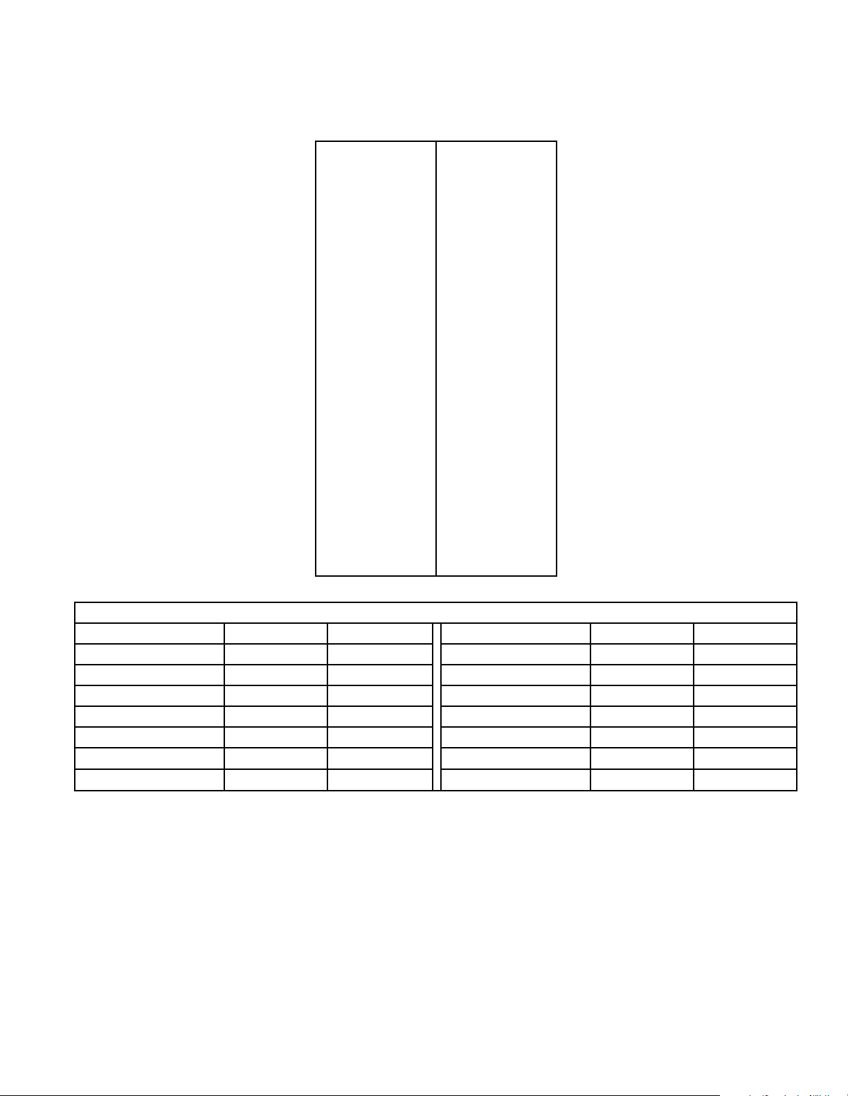
Conversion Table
Multiply By To Obtain Multiply By To Obtain
BTU .252 kCal Pounds / sq. in. .06895 Bars
BTU 1055 Joules Pounds / sq. in. .070 kg / sq. cm.
Inch 2.54 Centimeters Pounds (lbs.) .454 Kilograms
Inches W.C. .036 Pounds / sq. in. Boiler Horsepower 33479 BTU
Inches W.C. .249 kPa Boiler Horsepower 34.5 lbs. Steam / hr.
lbf / inch
3
ft
2
(psi)
.0369 kPa CFM .471 liters / second
28.32 Liters KW 3414 BTU / hr.
Information For Handy Reference
Date Purchased _________________________________________________________
Model No. _________________________ Serial No. __________________________
Dealer’s Name _________________________________________________________
NOTICE: For your own convenience and protection, record the above
information and retain your sales slip for this appliance. The model and serial
numbers will be found on the nameplate located on the tumbler. Refer to
Figure 1.
M414545
© Copyright, Alliance Laundry Systems LLC – DO NOT COPY or TRANSMIT
7
Page 10
PARTS ORDERING INFORMATION
If literature or replacement parts are required, contact the
source from whom the machine was purchased or
contact Alliance Laundry Systems at (920) 748-3950 for
the name and address of the nearest authorized parts
distributor.
For technical assistance, call (920) 748-3121.
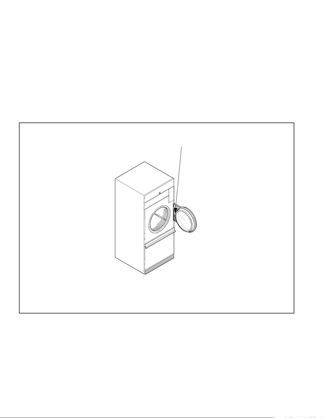
NAMEPLATE LOCATION
When calling or writing about your product, be sure to
mention model and serial numbers. Model and serial
numbers are located on nameplate as shown.
Nameplate
TMB1961N
Figure 1
8 M414545
© Copyright, Alliance Laundry Systems LLC – DO NOT COPY or TRANSMIT
Page 11
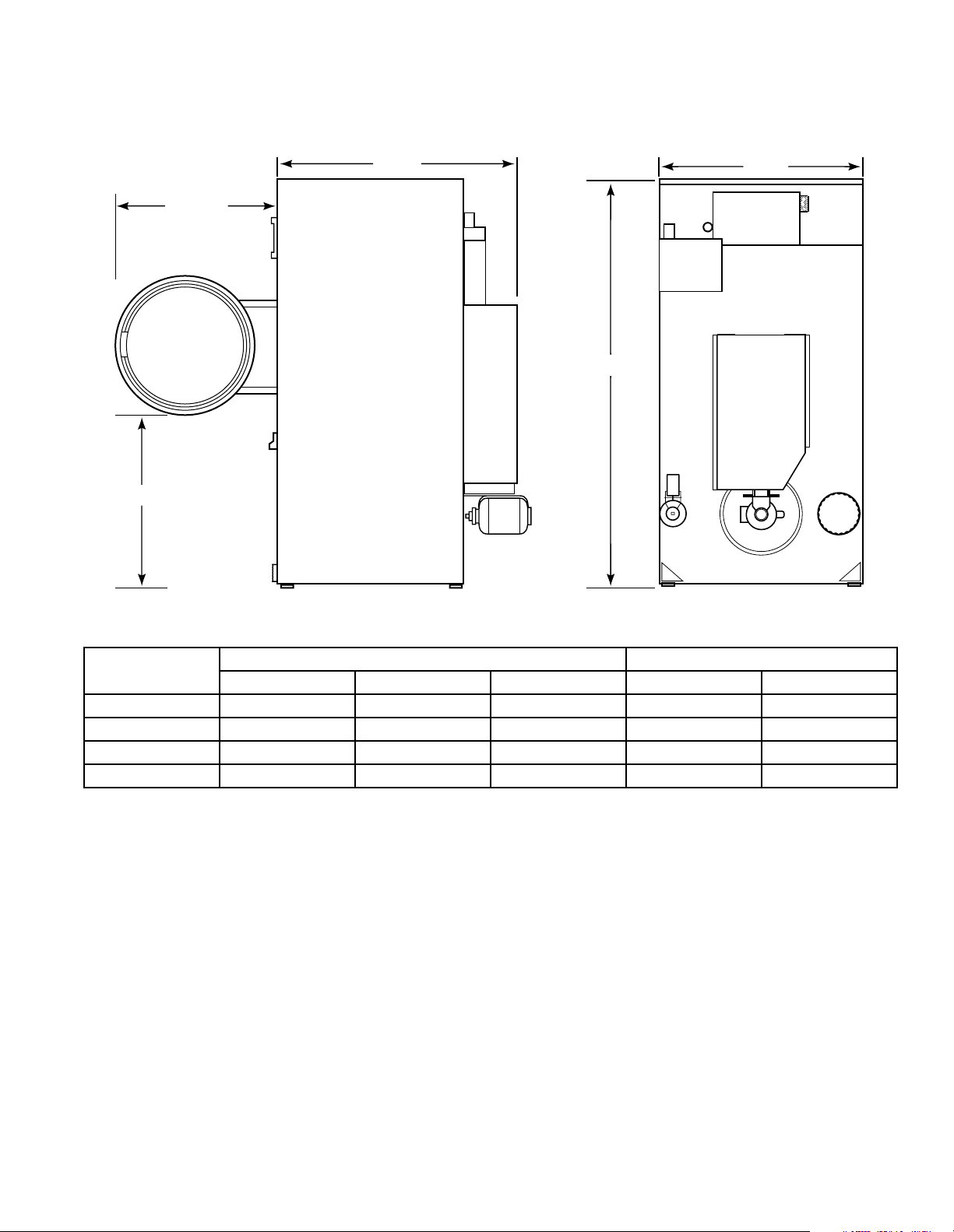
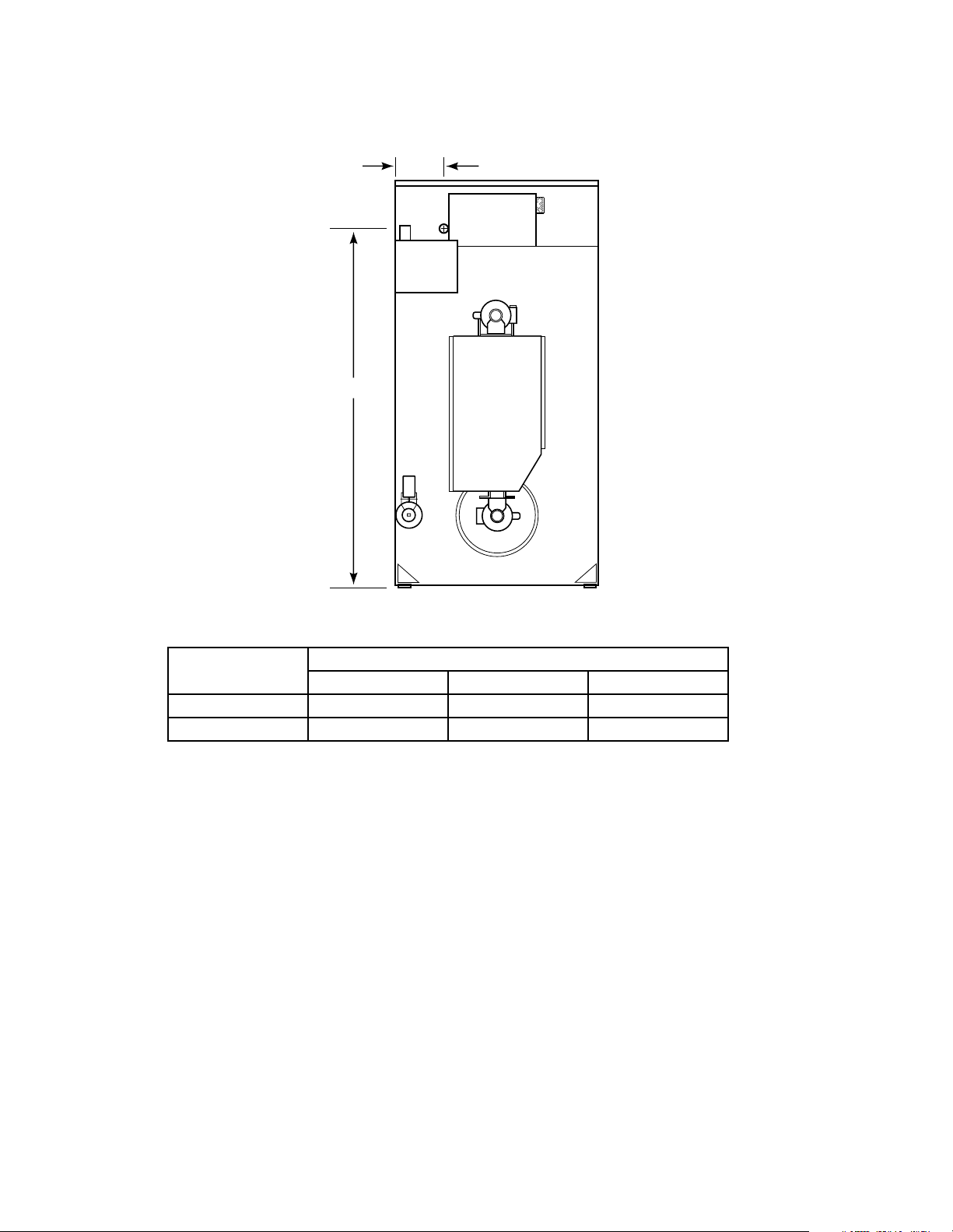
ROUGHING-IN DIMENSIONS AND SPECIFICATIONS
CABINET DIMENSIONS
OPENING
CLEARANCE
DEPTH
WIDTH
HEIGHT
T326IE3A
TUMBLER MODELS
30XG/30WE 72-1/4" (1835 mm) 28" (711 mm) 44-7/8" (1140 mm) 26-3/4" (679 mm) 30-3/4" (781 mm)
30CG/30EG 72-1/4" (1835 mm) 31-1/2" (800 mm) 46-11/16" (1186 mm) 28-1/4" (717 mm) 30-3/4" (781 mm)
30CE/30CSH 72-1/4" (1835 mm) 31-1/2" (800 mm) 44-7/8" (1140 mm) 28-1/4" (717 mm) 30-3/4" (781 mm)
30CSL 72-1/4" (1835 mm) 31-1/2" (800 mm) 45-1/32" (1144 mm) 28-1/4" (717 mm) 30-3/4" (781 mm)
HEIGHT WIDTH DEPTH OPENING CLEARANCE
OVERALL DOOR
M414545
© Copyright, Alliance Laundry Systems LLC – DO NOT COPY or TRANSMIT
9
Page 12
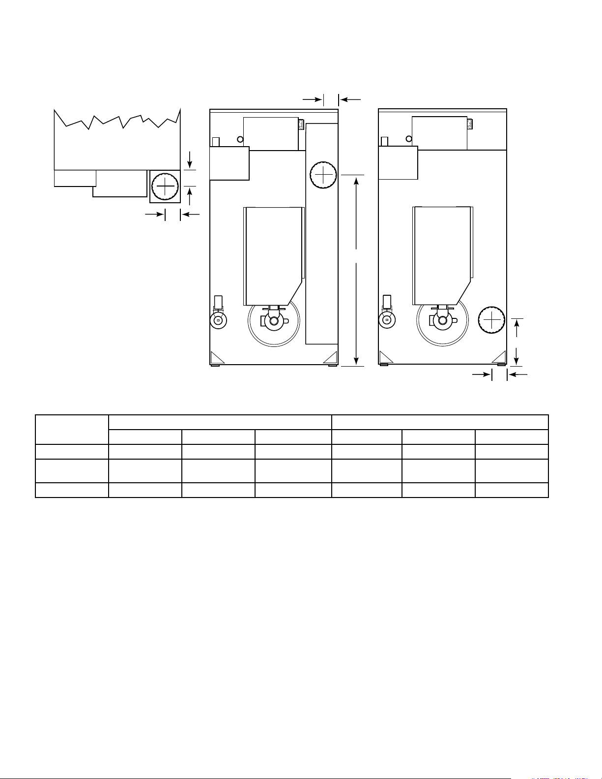
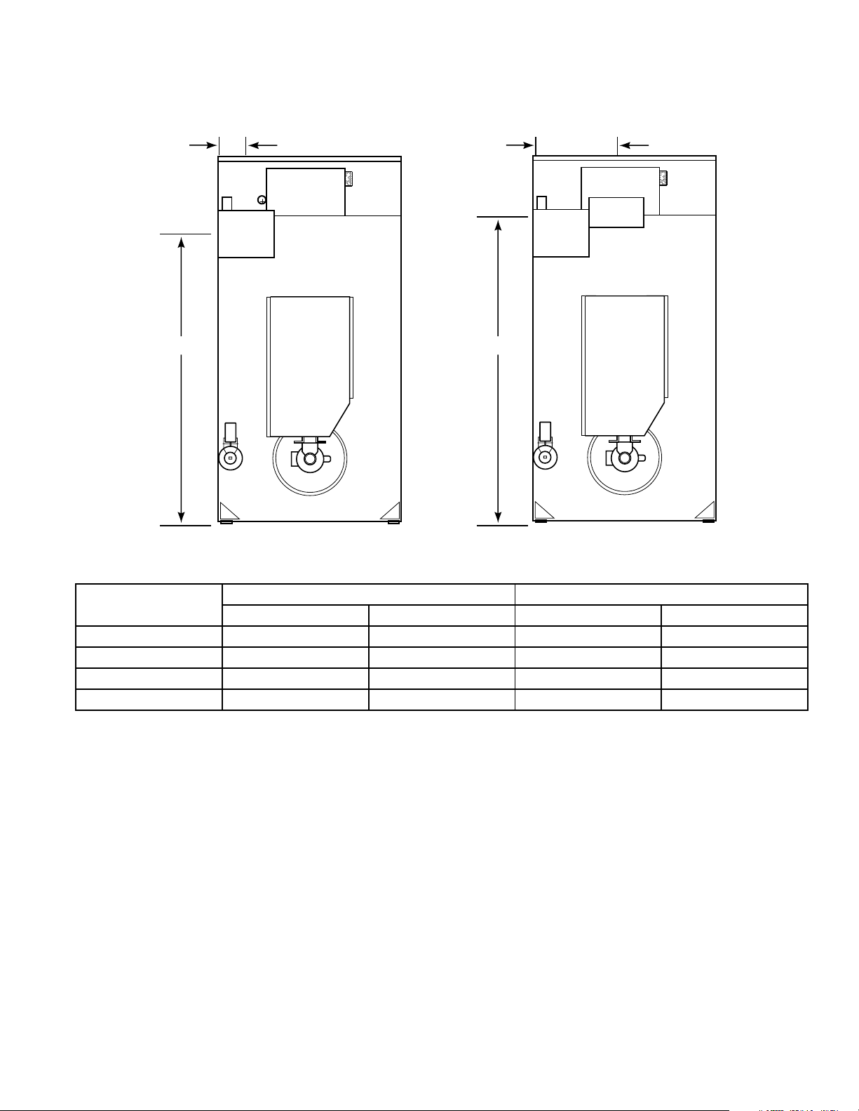
Roughing-In Dimensions and Specifications
Exhaust Thimble Locations
30XG and 30WE
ACROSS
ACROSS
DEPTH
HEIGHT
HEIGHT
ACROSS
TMB1959N
TUMBLER MODELS
30XG/30WE N/A N/A N/A 6" (152 mm) 3-3/8" (86 mm) 3-3/8" (86 mm)
30CG/30CE
30CSL/30CSH
30EG 8" (203 mm) 4-7/16" (113 mm) 55-3/8" (1407 mm) N/A N/A N/A
DIAMETER ACROSS HEIGHT DIAMETER ACROSS HEIGHT
8" (203 mm) 4-7/16" (113 mm) 21-7/8" (556 mm) N/A N/A N/A
HORIZONTAL EXHAUST VERTICAL EXHAUST
10 M414545
© Copyright, Alliance Laundry Systems LLC – DO NOT COPY or TRANSMIT
Page 13
Roughing-In Dimensions and Specifications
Steam Connection Locations
ACROSS
SPAN
STEAM
INLET
HEIGHT
STEAM
OUTLET
HEIGHT
TUMBLER
MODELS
30CSL
30CSH
T328IE3A
STEAM INLET STEAM OUTLET
DIAMETER ACROSS HEIGHT SPAN DIAMETER ACROSS HEIGHT SPAN
3/4" (19 mm)
I.D.
14" (356 mm) 68-3/4"
(1746 mm)
7-1/2"
(190 mm)
3/4" (19 mm)
I.D.
14" (356 mm) 61-1/4"
(1556 mm)
7-1/2"
(190 mm)
M414545
© Copyright, Alliance Laundry Systems LLC – DO NOT COPY or TRANSMIT
11
Page 14
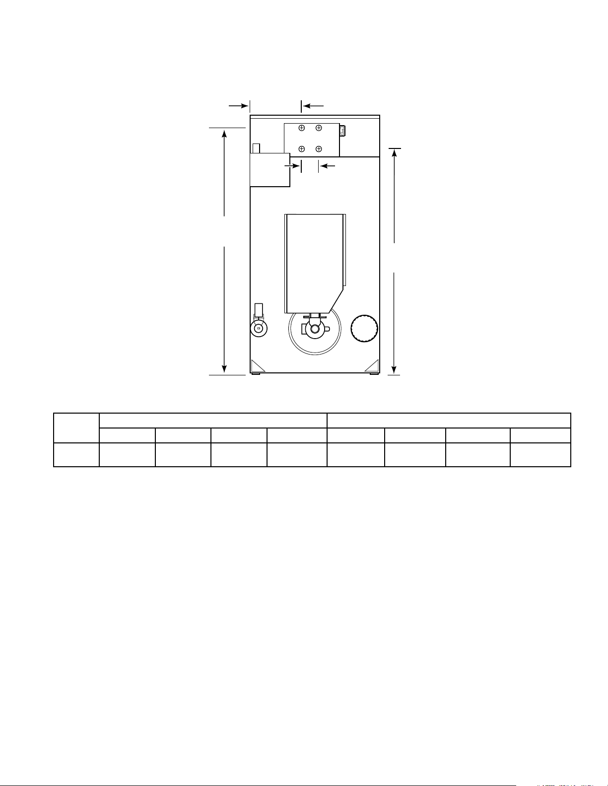
Roughing-In Dimensions and Specifications
Gas Connection Locations
ACROSS
HEIGHT
T329IE3A
TUMBLER
MODELS
30XG 1/2" (12.7 mm) 12-1/4" (311 mm) 62-1/8" (1578 mm)
30CG/30EG 1/2" (12.7 mm) 15" (381 mm) 62-1/8" (1578 mm)
DIAMETER (N.P.T.) ACROSS HEIGHT
GAS CONNECTION
12 M414545
© Copyright, Alliance Laundry Systems LLC – DO NOT COPY or TRANSMIT
Page 15
Roughing-In Dimensions and Specifications
330IE3
Electrical Connection Locations
HEIGHT
ACROSS
Gas & Steam
HEIGHT
Electric
ACROSS
T
A
TUMBLER
MODELS
30XG/30CG/30EG 65" (1651 mm) 3" (76 mm) N/A N/A
30WE N/A N/A 60" (1524 mm) 14" (356 mm)
30CE N/A N/A 60" (1524 mm) 16" (406 mm)
30CSL/30CSH 65" (1651 mm) 3" (76 mm) N/A N/A
ELECTRICAL SERVICE - GAS & STEAM MODELS ELECTRICAL SERVICE - ELECTRIC MODELS
HEIGHT ACROSS HEIGHT ACROSS
NOTE: These are approximate dimensions only.
M414545
© Copyright, Alliance Laundry Systems LLC – DO NOT COPY or TRANSMIT
13
Page 16
28" wide Gas Tumbler
Cabinet Finish: Electrostatically applied thermosetting polyester.
Cylinder: 26.5" x 30" (67.3 cm x 76.2 cm)
perforated galvanized steel with three baffles
Motor: 1/3 H.P., lifetime lubricated, internal overload protected
Gas Consumption: 75,000 BTU per hour (79.1 MJ/hr.)
Max. Airflow
Net Weight: 350 Pounds (159 kg) (approximate)
: 370 C.F.M. (175 liters/sec.)
28" wide Electric Tumbler
Cabinet Finish: Electrostatically applied thermosetting polyester.
Cylinder: 26.5" x 30" (67.3 cm x 76.2 cm)
perforated galvanized steel with three baffles
Motor: 1/3 H.P., lifetime lubricated, internal overload protected
Element: 21,000 Watts (60 Hz models)
Long life nichrome wire
18,000 Watts (50 Hz models)
Max. Airflow
Net Weight: 410 Pounds (184.5 kg) (approximate)
14 M414545
: 625 C.F.M. (295 liters/sec.)
© Copyright, Alliance Laundry Systems LLC – DO NOT COPY or TRANSMIT
Page 17
Gas Tumbler
Cabinet Finish: Electrostatically applied thermosetting polyester.
Cylinder: 30" x 30" (76.2 cm x 76.2 cm) perforated galvanized steel with three baffles;
30 pounds (13.6 kg) dry weight (cotton load)
Motor: 1/3 H.P., lifetime lubricated, internal overload protected
Energy Saver Models — 80,000 BTU per hour (84.4 MJ/hr.)
Gas Consumption:
Standard Models — 105,000 BTU per hour (110.8 MJ/hr.)
Gas Connection: 1/2 inch N.P.T.
Max. Airflow: Energy Saver Models — 250 C.F.M. (118 liters/sec.)
Standard Models — 625 C.F.M. (295 liters/sec.)
Net Weight: 450 Pounds (204 kg) (approximate)
Electric Tumbler
Cabinet Finish: Electrostatically applied thermosetting polyester.
Cylinder: 30" x 30" (76.2 cm x 76.2 cm) perforated galvanized steel with three baffles;
30 pounds (13.6 kg) dry weight (cotton load)
Motor: 1/3 H.P., lifetime lubricated, internal overload protected
Element: 21,000 Watts (all voltages)
Max. Airflow
Net Weight: 450 Pounds (204 kg) (approximate)
: 625 C.F.M. (295 liters/sec.)
Steam Tumbler
Cabinet Finish: Electrostatically applied thermosetting polyester.
Cylinder: 30" x 30" (76.2 x 76.2 cm) perforated galvanized steel with three baffles;
30 pounds dry weight (13.6 kg) (cotton load)
Motor: High Pressure (4 coils) 1/2 H.P.
Low Pressure (4 coils) 3/4 H.P.
Boiler Horsepower: 4 coil High Pressure – 3.7 Bhp (123,950 BTU/hr., 58 kg/hr, 31,235 kCal/hr.)
4 coil Low Pressure – 2.6 Bhp (87,100 BTU/hr., 40 kg/hr, 21,949 kCal/hr.)
Max. Airflow
Net Weight: 470 Pounds (214 kg) (approximate)
M414545
: 625 C.F.M. (295 liters/sec.)
© Copyright, Alliance Laundry Systems LLC – DO NOT COPY or TRANSMIT
15
Page 18

Notes
16 M414545
© Copyright, Alliance Laundry Systems LLC – DO NOT COPY or TRANSMIT
Page 19

Section III
Installation Instructions
RECEIVING INSPECTION
Upon delivery, visually inspect crate carton and parts for
any visible shipping damage. If the crate, carton or cover
are damaged or signs of possible damage are evident,
have the carrier note the condition on the shipping papers
before the shipping receipt is signed, or advise the carrier
of the condition as soon as it is discovered.
Remove the crate and protective cover as soon as possible
and check the items listed on the packing list. Advise the
carrier of any damaged or missing articles as soon as
possible. A written claim should be filed with the carrier
immediately if articles are damaged or missing.
IMPORTANT: Remove the shipping tape from the
two back draft dampers located in the exhaust
thimble.
MATERIALS REQUIRED (Obtain Locally)
GAS, ELECTRIC OR STEAM DRYING TUMBLERS
• One fused disconnect switch or circuit breaker.
GAS DRYING TUMBLERS ONLY
• One gas shut-off valve for gas service line to each
tumbler.
STEAM DRYING TUMBLERS ONLY
• One steam shut-off valve for steam service line to be
connected upstream of solenoid steam valve.
• Two steam shut-off valves for each condensate return
line.
• Flexible steam hoses with a 125 psig (pounds per
square inch gauge) (8.79 kg/sq. cm) working pressure
for connecting steam coils. Refer to Figure 9 and
Table 3.
• Two steam traps for steam coil outlet to condensate
return line.
• Two vacuum breakers for condensate return lines.
M414545
© Copyright, Alliance Laundry Systems LLC – DO NOT COPY or TRANSMIT
17
Page 20

POSITIONING THE TUMBLER
LEVELING THE TUMBLER
The tumbler may be removed from the skid before
moving it to the installation location or it may be moved
while still attached to the skid. To remove tumbler from
the skid, unscrew the four shipping capscrews (one at
each corner) and remove the tumbler from the skid. The
lint panel door will have to be removed in order to remove
the two front capscrews.
NOTE: Do not throw these four capscrews away —
they are the leveling legs.
Screw the four leveling legs back into the level adjusting
fittings from the top.
Slide the tumbler to its permanent location and level.
Keep the tumbler as close to the floor as possible. The
tumbler must rest firmly on the floor so weight of tumbler
is evenly distributed. Tumbler must not rock.
Each tumbler should be leveled within 1/8 inch (3.2 cm)
from front to rear, and 1/8 inch (3.2 cm) from side to side.
Check front to rear level by rotating the clothes cylinder
until one rib is at the bottom, then place a level on the rib.
Side to side level should be checked by placing a level on
the front and rear of the top panel.
18 M414545
© Copyright, Alliance Laundry Systems LLC – DO NOT COPY or TRANSMIT
Page 21
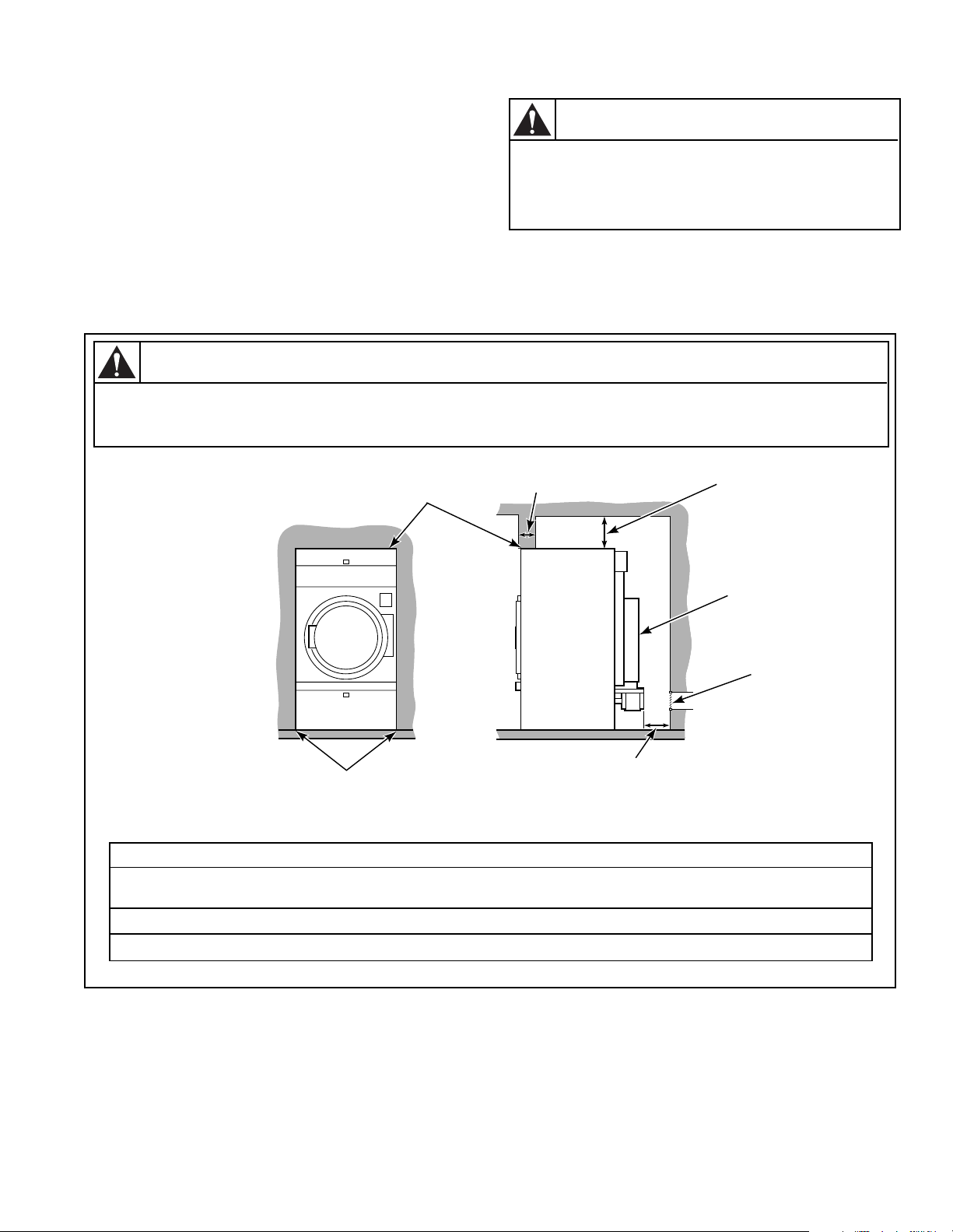
TUMBLER ENCLOSURE CONSTRUCTION
IMPORTANT: DO NOT block the airflow at the rear
of the tumbler with laundry or other articles. Doing
so would prevent adequate air supply to the
combustion chamber of the tumbler.
A typical tumbler enclosure is shown in Figure 2. Note
that the enclosure touches the tumbler top and side
To reduce the risk of serious injury, install
lockable door(s) to prevent public access
to rear of tumblers.
panels. Also, note the minimum and maximum
dimensions. Be aware that there may be local codes and
ordinances which must be complied with.
IMPORTANT: Install tumblers with sufficient
clearance for servicing and operation. Refer to
Figure 2.
WARNING
To reduce the risk of severe injury, clearance of tumbler cabinet from combustible
construction must conform to the minimum clearances.
WARNING
W055
W056
12" (30.5 cm)
MINIMUM
CLEARANCE
PERMITTED
FOR REMAINDER
GUARD
PROVISION
MAKE-UP
T038IE3D
NOTE: Shaded areas
indicate adjacent
structure.
0" CLEARANCE PERMITTED
FOR FIRST 4" (10.16 cm)
0" CLEARANCE
4" (10.16 cm)
MAXIMUM
24" (61 cm) MINIMUM
36" (91.4 cm) RECOMMENDED
FOR MAINTENANCE PURPOSES
Minimum Recommended Clearances
Model Top
First 4" (10.2 cm)
To p
(Remainder)
Back Sides
28" 0" (0.0 cm) 12" (30.5 cm) 24" (61 cm) 0" (0 cm)
FOR
AIR
31.5" 0" (0.0 cm) 12" (30.5 cm) 24" (61 cm) 0" (0 cm)
Figure 2
M414545
© Copyright, Alliance Laundry Systems LLC – DO NOT COPY or TRANSMIT
19
Page 22
FACILITIES REQUIRED
To assure compliance, consult local building code
requirements.
WARNING
A drying tumbler produces combustible
lint. To reduce the risk of fire, the tumbler
must be exhausted to the outdoors.
W057
FLOOR
The tumbler must be installed on a level floor capable of
supporting 100 pounds per square foot (488.3 kg/sq. m).
Floor covering materials such as carpeting or tile must be
removed.
LAYOUT
Whenever possible, tumblers should be installed along an
outside wall where duct length can be kept to a minimum,
and make-up air can be easily accessed. Construction
must not block the airflow at the top rear of the tumbler.
Doing so would prevent adequate air supply to the
tumbler’s combustion chamber.
VENTING
For maximum efficiency and minimum lint
accumulation, tumbler air must be exhausted to the
outdoors by the shortest possible route.
Proper sized exhaust ducts are essential for proper
operation. All elbows should be sweep type. Exhaust
ducts must be assembled so the interior surfaces are
smooth, so the joints do not permit the accumulation of
lint. Do not use sheet metal screws to join vent sections.
Improperly sized or assembled ductwork causes excess
back pressure which results in slow drying, lint collecting
in the duct, lint blowing back into the room, and
increased fire hazard.
preferred to exhaust tumbler(s) individually to the
outdoors. At no point may the cross area of installed
venting be less than the cross area of the exhaust
thimble of the tumbler.
The maximum allowable length venting is 14 feet (4.3
m) and two 90° elbows or equivalent. If the equivalent
length of a duct required for an installation exceeds the
maximum allowable equivalent length, the diameter of
a round duct must be increased by 10% for each
additional 20 feet (6.1 m). Cross section area of a
rectangular duct must be increased by 20% for each
addtional 20 feet (6.1 m). To determine equivalent
venting, Refer to Tabl e 1 .
DUCT
DIAMETER
6" (15.2 cm)
8" (20.3 cm)
10" (25.40 cm)
12" (30.48 cm)
14" (35.56 cm)
16" (40.64 cm)
18" (45.72 cm)
Equivalent Length (feet) = 1.7 x Duct Diameter
(inches)
Example: A 12" diameter duct’s equivalent
length of 14 feet of duct and two 90° elbows is:
Equivalent Length = 14 feet + (2) 90° elbows
With the tumbler in operation, airflow at any point in
the duct must be at least 1200 feet per minute (366 m./
min.) to insure that the lint remains airborne.
EQUIVALENT LENGTH OF
STRAIGHT DUCT
One 90° elbow = 7 feet (2.1 m)
One 90° elbow = 9.3 feet (2.83 m)
One 90° elbow = 11.6 feet (3.5 m)
One 90° elbow = 14 feet (4.3 m)
One 90° elbow = 16 feet (4.9 m)
One 90° elbow = 18.7 feet (5.7 m)
One 90° elbow = 21 feet (6.4 m)
Table 1
= 14 feet + 14 feet + 14 feet
= 42 feet (12.8 m)
Exhaust ducts shall be constructed of sheet metal or
other noncombustible material. Such ducts must be
equivalent in strength and corrosion resistance to
ducts made of galvanized sheet steel not less than
0.0195 inches (0.495 mm) thick.
Where the exhaust duct pierces a combustible wall or
ceiling, an opening having a diameter of 4 inches (10.2
cm) larger than the diameter of the exhaust duct shall be
provided, with the duct centered in the opening. When
ducts pass through walls, ceilings, floors or partitions, the
space around the duct shall be sealed with noncombustible material. Refer to Figures 3, 4 and 5.
• Individual Venting
For maximum efficiency and performance, it is
20 M414545
© Copyright, Alliance Laundry Systems LLC – DO NOT COPY or TRANSMIT
Page 23

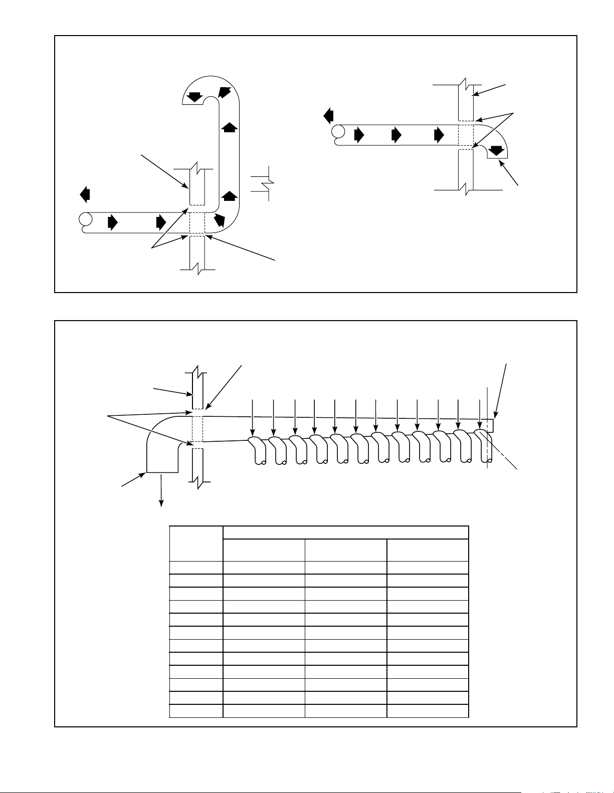
• Collector Venting
While it is preferable to exhaust tumblers individually
to the outdoors, a main collector duct may be used if it
is sized accordingly. Refer to Figure 5. This
illustration indicates minimum diameters, and should
be increased if the collector length exceeds 20 feet
(6.1 m). The collector duct may be rectangular in cross
section, as long as the area is not reduced. Provisions
should be made for lint removal and cleaning of the
collector duct.
The collector duct must be tapered. Refer to Figure 5.
The individual tumbler ducts must enter the collector
duct at a 45° angle in the direction of airflow. Never
connect a tumbler duct at a 90° angle to the collector
duct. Doing so will cause excessive back pressure,
resulting in poor performance. Never connect two
tumbler exhaust ducts directly across from each
other at the point of entry to the collector duct.
The collector system must be designed so the static
back pressure measured 12 inches (30.5 cm) from the
exhaust thimble does not exceed the maximum
allowable pressure specified on the installation sticker
on the rear of the tumbler. This must be measured with
all tumblers running that are vented into the collector.
At a minimum, the National Fuel Gas Code requires
tumblers to have at least one square inch (6.5 sq. cm)
of opening for every 1000 BTU/hr. of input rating for
proper combustion.
Example: A tumbler with a rated input of 120,000
BTU/hr. requires 120 square inches of free
opening.
The additional opening recomended by the
manufacturer is required for optimum drying and
reliability.
Protective louvers in the opening to the outdoors can
reduce air movement by approximately 40 percent. The
opening must compensate for the area taken up by the
louvers.
The make-up air openings for a room containing
tumbler(s) and/or gas fired hot water heater or other
gravity vented appliances must be increased sufficiently
to prevent downdrafts in any of the vents when all
tumblers are in operation. Do not locate gravity vented
appliances between tumbler(s) and make-up air
openings. If it is necessary to duct make-up air to the
tumbler(s), increase the area of the duct work by 25
percent to compensate for any restriction in air
movement.
MAKE-UP AIR
A tumbler is forced air exhausted and requires provisions
for make-up air to replace the air exhausted by the
tumbler.
IMPORTANT: Do not obstruct the flow of
combustion and ventilation air.
Recommended make-up air opening to the outside is
144 inches
2
(928 cm2).
M414545
© Copyright, Alliance Laundry Systems LLC – DO NOT COPY or TRANSMIT
21
Page 24
WARNING
WARNING
Solvent gases and vapors from dry
cleaning machines create acids when
drawn through the heater of a drying
tumbler. These acids are corrosive to the
drying tumbler as well as to the laundry
load being dried. Be sure make-up air is
free of solvent gases and vapors.
If the dry cleaning machines are in the
same area as the tumbler, then the
tumbler make-up air must come from a
source free of solvent gases and vapors.
W058
FOR BEST PERFORMANCE
provide an individual exhaust
duct for each drying tumbler.
Do not install a hot water heater
in room containing drying
tumblers. It is better to
have the water heater in
a separate room with a
separate air inlet.
To reduce the risk of fire and
accumulation of combustible gases, DO
NOT exhaust tumbler air into a window
well, gas vent, chimney or enclosed,
unventilated area such as an attic wall,
ceiling, crawl space under a building, or
concealed space of a building.
W059
NOTE: Do not install wire
mesh or screen in this
opening as lint will build up
and prevent proper discharge
of air from drying tumblers.
ROOF 30" (76.2 CM)
T075IE3A
REMOVABLE STRIP OF PANEL IN FRAMING WALL
TO PERMIT REMOVAL OF DRYING TUMBLER
T108IE3A
FROM FRAMING WALL
ONE
DRYING
TUMBLER
TWO
DRYING
TUMBLERS
THREE
DRYING
TUMBLERS
ROOF 30" (76.2 cm)
PARTITION OR
BULKHEAD
CONSULT YOUR LOCAL BUILDING
CODE FOR REGULATIONS WHICH
MAY ALSO APPLY
NOTE: Inside of duct shall be
smooth. Do not use sheet
metal screws to join sections.
CEILING
WALL
36 INCHES
(91.4 cm)
RECOMMENDED
SERVICE AREA
24 INCHES
(61.0 cm)
MINIMUM
T108IE3C
Figure 3
22 M414545
© Copyright, Alliance Laundry Systems LLC – DO NOT COPY or TRANSMIT
Page 25
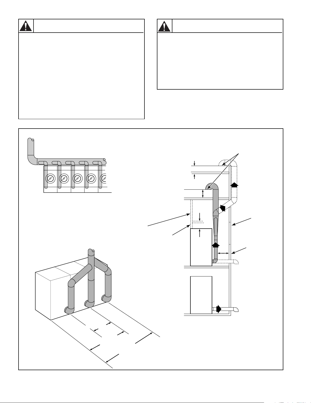
VERTICAL EXHAUST INSTALLATION
HORIZONTAL EXHAUST INSTALLATION
WALL
CONNECT TO
TUMBLER
2" (5.1 cm)
MINIMUM
WALL
2" (5.1 cm)
MINIMUM
WALL
CONNECT TO
TUMBLER
EXHAUST AIR FLOW
MAXIMUM LENGTH OF
DUCT 14 FEET
(4.3 m)
NOTE: WHERE THE EXHAUST DUCT PIERCES A COMBUSTIBLE WALL
OR CEILING, AN OPENING HAVING A DIAMETER FOUR INCHES (10.2 cm)
LARGER THAN THE DIAMETER OF THE EXHAUST DUCT SHALL BE
PROVIDED, AND THE EXHAUST DUCT CENTERED WITHIN THE OPENING.
Figure 4
NOTE: WHERE THE EXHAUST DUCT PIERCES A COMBUSTIBLE WALL
OR CEILING, AN OPENING HAVING A DIAMETER FOUR INCHES (10.2 cm)
LARGER THAN THE DIAMETER OF THE EXHAUST DUCT SHALL BE
PROVIDED, AND THE EXHAUST DUCT CENTERED WITHIN THE OPENING.
T030IE3B
2" (5.1 cm)
MINIMUM
EXHAUST
OUTLET
NO SCREEN
OR CAP
INSPECTION OR
CLEANOUT COVER
ALKJ I HGF E DCB
NO SCREEN
OR CAP
AIR OUT
DUCT
STATION
28" WIDE
GAS & ELEC.
MINIMUM DIAMETER
30 LB.
GAS & ELEC.
30 LB. STEAM
A 7" (17.8 cm) 10" (25.4 cm) 10" (25.4 cm)
B 10" (25.4 cm) 12" (30.5 cm) 14" (35.6 cm)
C 12" (30.5 cm) 15" (38.1 cm) 17" (43.2 cm)
D 14" (35.6 cm) 17" (43.2 cm) 20" (50.8 cm)
E 16" (40.6 cm) 19" (48.3 cm) 22" (55.9 cm)
F 18" (45.7 cm) 21" (53.3 cm) 24" (61.0 cm)
G 19" (48.3 cm) 23" (58.4 cm) 26" (66.0 cm)
H 20" (50.8 cm) 25" (63.5 cm) 28" (71.1 cm)
I 22" (55.9 cm) 26" (66.0 cm) 30" (76.2 cm)
J 23" (58.4 cm) 27" (68.6 cm) 31" (78.0 cm)
K 24" (61.0 cm) 29" (73.9 cm) 33" (83.8 cm)
L 25" (63.5 cm) 30" (76.2 cm) 34" (86.4 cm)
Figure 5
45˚
T056IE3B
M414545
© Copyright, Alliance Laundry Systems LLC – DO NOT COPY or TRANSMIT
23
Page 26
GAS REQUIREMENTS
WARNING
To reduce the risk of fire or explosion, DO
NOT CONNECT THE GAS LINE TO THE
TUMBLER IF THE GAS SERVICE IS NOT
THE SAME AS THAT SPECIFIED ON THE
TUMBLER SERIAL PLATE! It will first be
necessary to convert the gas burner
orifice and gas valve. Appropriate
conversion kits are available.
W060
IMPORTANT: Any product revisions or conversions
must be made by the Manufacturer’s Authorized
Dealers, Distributors or local service personnel.
WARNING
The tumbler and its individual shut-off
valve must be disconnected from the gas
supply piping system during any pressure
testing of that system at test pressures in
excess of 1/2 psig (3.45 kPa).
The size of gas service pipe is dependent upon many
variables (lengths, tees, etc.). Specific pipe size
information should be obtained from the gas supplier.
Refer to Ta b le 2 for general pipe size.
A dirt and water vapor pipe trap must be furnished and
installed by customer. Refer to Figure 6.
It is important that equal pressure be maintained at all
tumbler gas connections. This can best be done by
installing a one inch (2.54 cm) pipe gas loop. Refer to
Figure 7.
WARNING
To reduce the risk of fire or explosion, if
the tumbler is to be connected to
Liquefied Petroleum (L.P.) gas, a vent to
the outdoors must be provided in the
room where the tumbler is installed.
W062
NATURAL GAS service must be supplied at 6-1/2 ±
1-1/2 inch water column pressure (1.62 ± .37 kPa).
L.P. GAS service must be supplied at 11 ± .3 inch water
column pressure (2.74 ± .07 kPa).
The tumbler must be isolated from the gas
supply piping system by closing its
individual manual shut-off valve during
any pressure testing of the gas supply
piping system at test pressure equal to or
less than 1/2 psig (3.45 kPa).
IMPORTANT: The installation must comply with
local codes or, in the absence of local codes:
• with the latest edition of the “National Fuel
Gas Code”, ANSI Z223.1 in the U.S.A.
• with CAN1-B149.1 or CAN1-B149.2 in
Canada
• and Australian Gas Association/Australian
L.P. Gas Association requirements in Australia
W061
24 M414545
© Copyright, Alliance Laundry Systems LLC – DO NOT COPY or TRANSMIT
Page 27
WARNING
Check all pipe connections, internal and
external, for gas leaks using a soapy
solution. To reduce the risk of explosion or
fire, DO NOT USE AN OPEN FLAME TO
CHECK FOR GAS LEAKS! Gas
connections should be checked annually
for leakage.
W063
GAS LINE
TO
DRYER
CONTROLS
SHUT-OFF
VALVE
DIRT AND
WATER VAPOR
TRAP
1/8" (.32 cm) N.P.T. plugged
tapping accessible for
pressure testing. Gauge
connection located upstream
from dryer main manual
shut-off
Figure 6
GAS SUPPLY
PIPING SYSTEM
GAS
“T” FITTING
6 INCHES (15.2 cm)
MINIMUM GAS PIPE
GAS
PIPE CAP
T135IE1A
M414545
© Copyright, Alliance Laundry Systems LLC – DO NOT COPY or TRANSMIT
25
Page 28
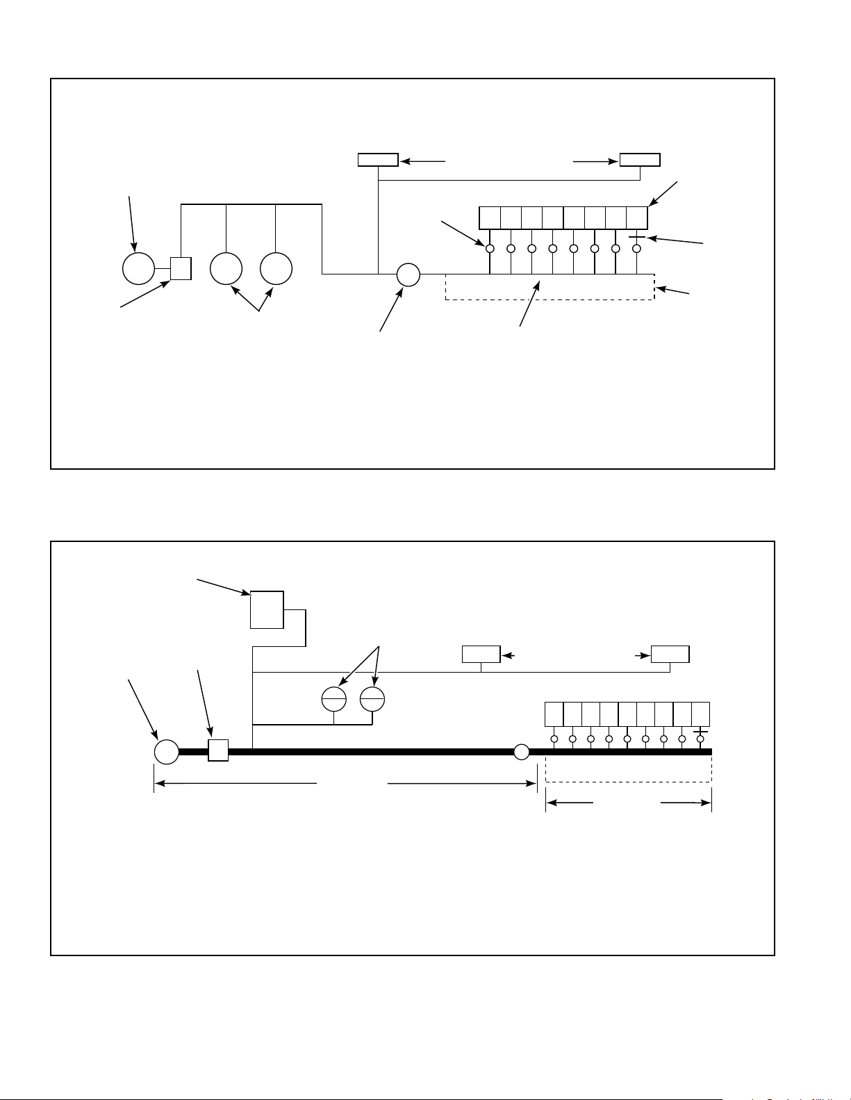
Example of Gas Loop Piping
IMPORTANT: Gas loop piping must be installed
as illustrated to equalize gas pressure for all
tumblers connected to single gas service.
Other gas using appliances should be
connected upstream from loop.
MAIN
REGULATOR
GAS SPACE HEATER
TUMBLERS
GAS
SHUT-OFF
VALVES
GAS LINE
PRESSURE TAP
GAS
METER
IMPORTANT: Line pressure must be maintained at 6-1/2 ± 1-1/2 water column inches (1.62 ± .37 kPa) for Natural Gas
(11 ± .3 water column inches for L.P. Gas) (2.74 ± .07 kPa) with all gas appliances running (tumblers, water heaters, space heaters,
furnace, etc.).
An in-line pressure regulator may be required on Natural Gas models if the line pressure exceeds eight water column inches (2.00
kPa) pressure with all gas appliances firing.
GAS WATER
HEATERS
PRESSURE
REGULATOR
(If required)
NOTE: Minimum pipe size to
tumbler is 1/2" (12.7 mm)
T034IE3D
ONE INCH
(2.54 cm)
GAS LOOP
Figure 7
Example of Gas Supply Piping
NOTE: See BTU/HR. rating
on dryer nameplate.
GAS SPACE
HEATERS
(70,000 BTU/HR. each)
GAS TUMBLER DRYERS
(75,000 BTU/HR. each)
123456789
FURNACE
(120,000 BTU/HR.)
MAIN
REGULATOR
GAS
GAS WATER
HEATERS
(400,000 BTU/HR. each)
GAS
METER
PIPE
PRESSURE
25' (7.6 m)
SAMPLE CALCULATIONS:
Equivalent Length = Total length of main gas supply pipe from
the gas meter to the far end of the tumbler dryers.
= 25' + 19' (7.6 m + 5.8 m) gas supply pipe.
= 44' (13.4 m) Total Gas Liner
The main supply pipe diameter should be 2" (5.08 cm). Refer to Table 2.
REGULATOR
Total BTU/HR = The sum of the BTU/HR. of all
tumblers being fed by the main
gas supply pipe.
= 9 x 75,000
= 675,000 BTU/HR.
19' (5.8 m)
19' (5.8 m)
TMB1960N
Figure 8
26 M414545
© Copyright, Alliance Laundry Systems LLC – DO NOT COPY or TRANSMIT
Page 29
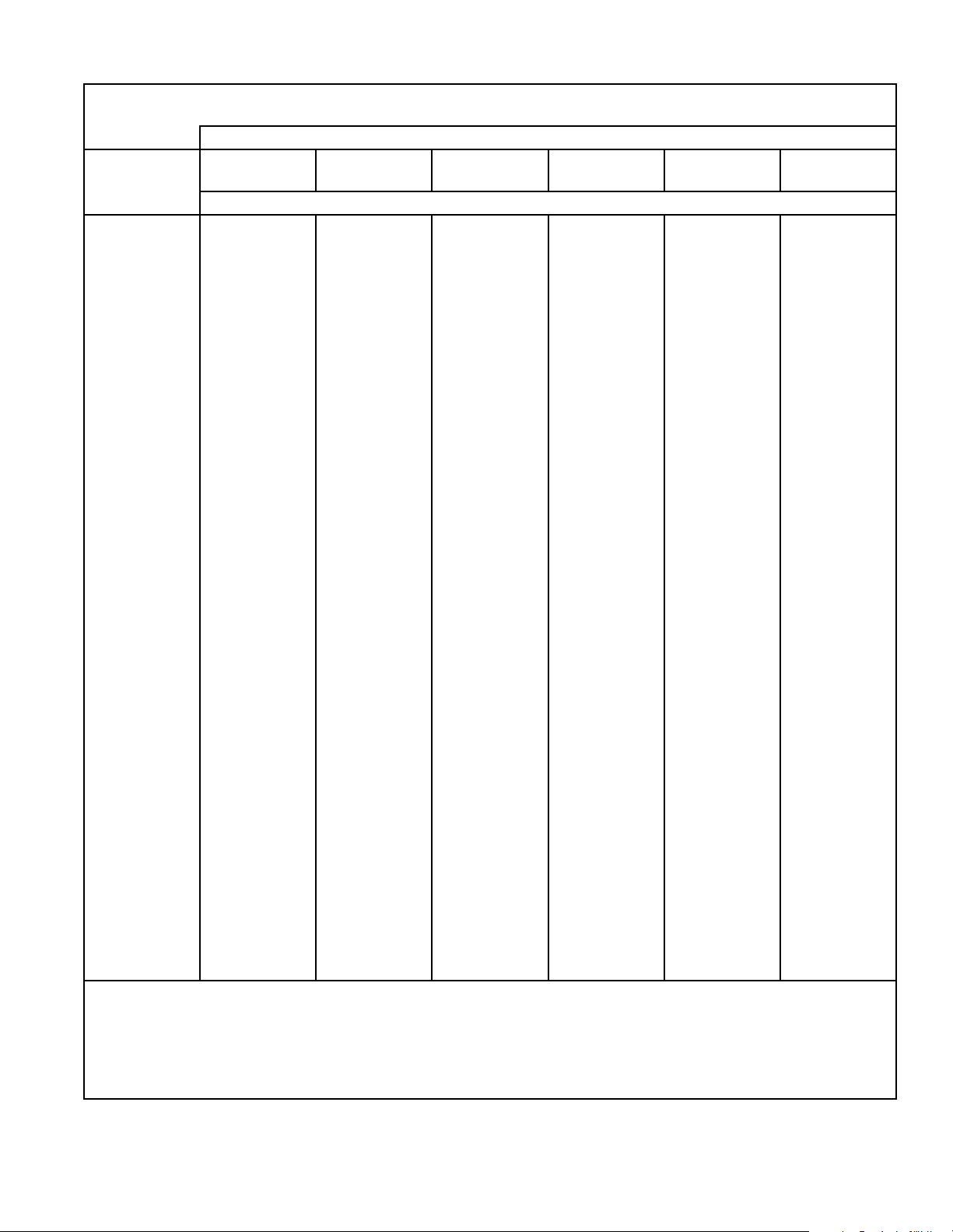
GAS PIPE SIZE REQUIRED FOR 1,000 BTU NATURAL GAS — .64 SPECIFIC GRAVITY
GAS
APPLIANCES
TOTAL
BTU/HR.
100,000
AT 6½ ± 1½ INCH (1.62 ± .37 kPa) WATER COLUMN PRESSURE
25 FT.
(7.63 m)
BASED ON 0.3" WATER COLUMN PRESSURE DROP FOR LENGTH GIVEN
¾" (19.05mm)
50 FT.
(15.25 m)
¾" (19.05mm)
EQUIVALENT LENGTH
75 FT.
(22.88 m)
1" (2.54cm)
100 FT.
(30.50 m)
1" (2.54cm)
125 FT.
(38.13 m)
1" (2.54cm)
150 FT.
(45.75 m)
1" (2.54cm)
120,000
140,000
160,000
180,000
200,000
300,000
400,000
500,000
600,000
700,000
800,000
900,000
1,000,000
1,100,000
1,200,000
1,300,000
1,400,000
1,500,000
¾" (19.05mm)
¾" (19.05mm)
¾" (19.05mm)
1" (2.54cm)
1" (2.54cm)
1" (2.54cm)
1¼" (3.18cm)
1¼" (3.18cm)
1½" (3.81cm)
1½" (3.81cm)
1½" (3.81cm)
2" (5.08cm)
2" (5.08cm)
2" (5.08cm)
2" (5.08cm)
2" (5.08cm)
2" (5.08cm)
2" (5.08cm)
1" (2.54cm)
1" (2.54cm)
1" (2.54cm)
1" (2.54cm)
1" (2.54cm)
1¼" (3.18cm)
1¼" (3.18cm)
1½" (3.81cm)
1½" (3.81cm)
2" (5.08cm)
2" (5.08cm)
2" (5.08cm)
2" (5.08cm)
2" (5.08cm)
2" (5.08cm)
2½" (6.35cm)
2½" (6.35cm)
2½" (6.35cm)
1" (2.54cm)
1" (2.54cm)
1" (2.54cm)
1" (2.54cm)
1¼" (3.18cm)
1¼" (3.18cm)
1½" (3.81cm)
1½" (3.81cm)
2" (5.08cm)
2" (5.08cm)
2" (5.08cm)
2" (5.08cm)
2" (5.08cm)
2½" (6.35cm)
2½" (6.35cm)
2½" (6.35cm)
2½" (6.35cm)
2½" (6.35cm)
1" (2.54cm)
1" (2.54cm)
1¼" (3.18cm)
1¼" (3.18cm)
1¼" (3.18cm)
1½" (3.81cm)
1½" (3.81cm)
2" (5.08cm)
2" (5.08cm)
2" (5.08cm)
2" (5.08cm)
2½" (6.35cm)
2½" (6.35cm)
2½" (6.35cm)
2½" (6.35cm)
2½" (6.35cm)
2½" (6.35cm)
2½" (6.35cm)
1" (2.54cm)
1" (2.54cm)
1¼" (3.18cm)
1¼" (3.18cm)
1¼" (3.18cm)
1½" (3.81cm)
1½" (3.81cm)
2" (5.08cm)
2" (5.08cm)
2" (5.08cm)
2½" (6.35cm)
2½" (6.35cm)
2½" (6.35cm)
2½" (6.35cm)
2½" (6.35cm)
2½" (6.35cm)
3" (7.62cm)
3" (7.62cm)
1" (2.54cm)
1¼" (3.18cm)
1¼" (3.18cm)
1¼" (3.18cm)
1½" (3.81cm)
1½" (3.81cm)
2" (5.08cm)
2" (5.08cm)
2" (5.08cm)
2½" (6.35cm)
2½" (6.35cm)
2½" (6.35cm)
2½" (6.35cm)
2½" (6.35cm)
2½" (6.35cm)
3" (7.62cm)
3" (7.62cm)
3" (7.62cm)
1,600,000
1,700,000
1,800,000
1,900,000
2,000,000
2,200,000
2,400,000
2,600,000
2,800,000
3,000,000
FOR L. P. GAS, CORRECT THE TOTAL BTU/HR. BY MULTIPLYING IT BY 0.6. THE ANSWER IS THE
EQUIVALENT BTU ON THE ABOVE CHART.
IMPORTANT: The installation must conform with local codes or, in the absence of local codes:
• with the latest edition of the “National Fuel Gas Code”, ANSI Z223.1 in the U.S.A.,
• with CAN1-B149.1 or CAN1-B149.2 in Canada,
2" (5.08cm)
2" (5.08cm)
2½" (6.35cm)
2½" (6.35cm)
2½" (6.35cm)
2½" (6.35cm)
2½" (6.35cm)
2½" (6.35cm)
2½" (6.35cm)
2½" (6.35cm)
2½" (6.35cm)
2½" (6.35cm)
2½" (6.35cm)
2½" (6.35cm)
2½" (6.35cm)
3" (7.62cm)
3" (7.62cm)
3" (7.62cm)
3" (7.62cm)
3" (7.62cm)
2½" (6.35cm)
2½" (6.35cm)
3" (7.62cm)
3" (7.62cm)
3" (7.62cm)
3" (7.62cm)
3" (7.62cm)
3" (7.62cm)
3" (7.62cm)
3½" (8.89cm)
3" (7.62cm)
3" (7.62cm)
3" (7.62cm)
3" (7.62cm)
3" (7.62cm)
3" (7.62cm)
3" (7.62cm)
3½" (8.89cm)
3½" (8.89cm)
3½" (8.89cm)
3" (7.62cm)
3" (7.62cm)
3" (7.62cm)
3" (7.62cm)
3" (7.62cm)
3½" (8.89cm)
3½" (8.89cm)
3½" (8.89cm)
3½" (8.89cm)
3½" (8.89cm)
3½" (8.89cm)
3½" (8.89cm)
3½" (8.89cm)
3½" (8.89cm)
3½" (8.89cm)
• and Australian Gas Association / Australian LP Gas Association requirements in Australia.
Table 2
M414545
© Copyright, Alliance Laundry Systems LLC – DO NOT COPY or TRANSMIT
3" (7.62cm)
3" (7.62cm)
3" (7.62cm)
3" (7.62cm)
4" (10.16cm)
27
Page 30
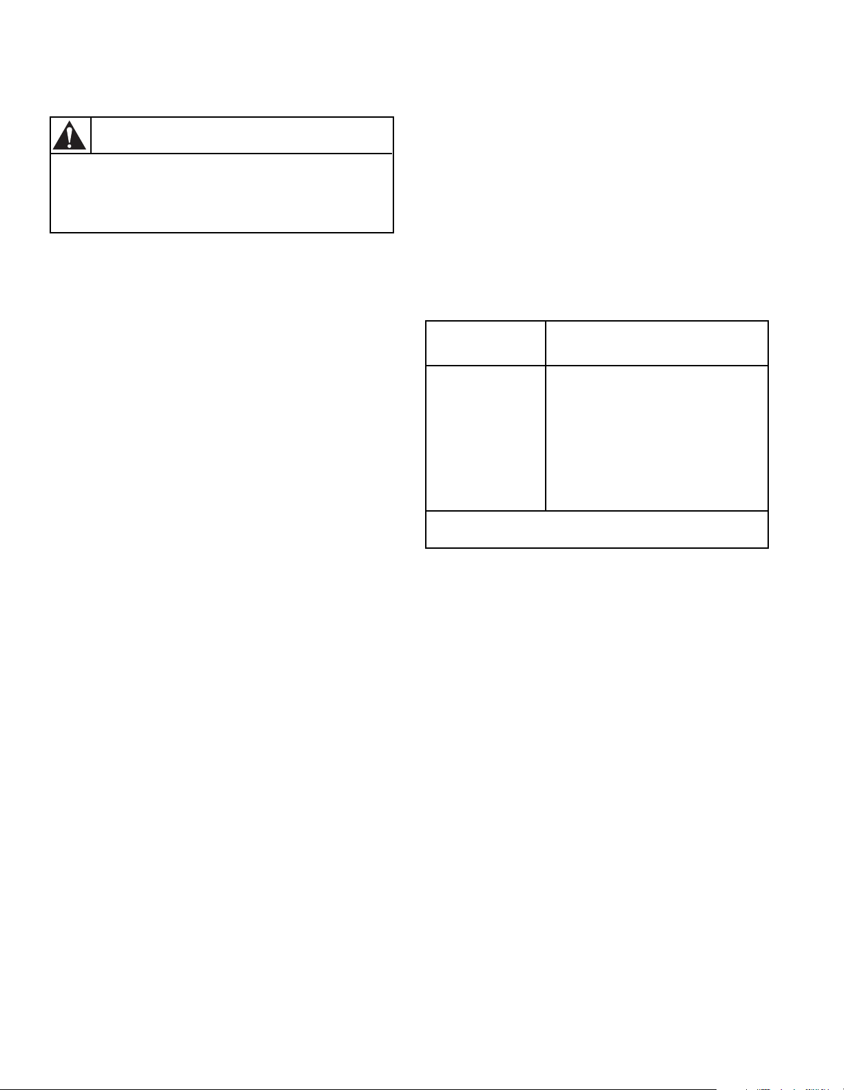
STEAM REQUIREMENTS (Steam Drying Tumblers)
The size of the steam service pipe is dependent upon
many variables (length, tees, high pressure system, low
pressure system, etc.). Specific pipe size information
should be obtained from the steam system supplier or a
qualified steam fitter.
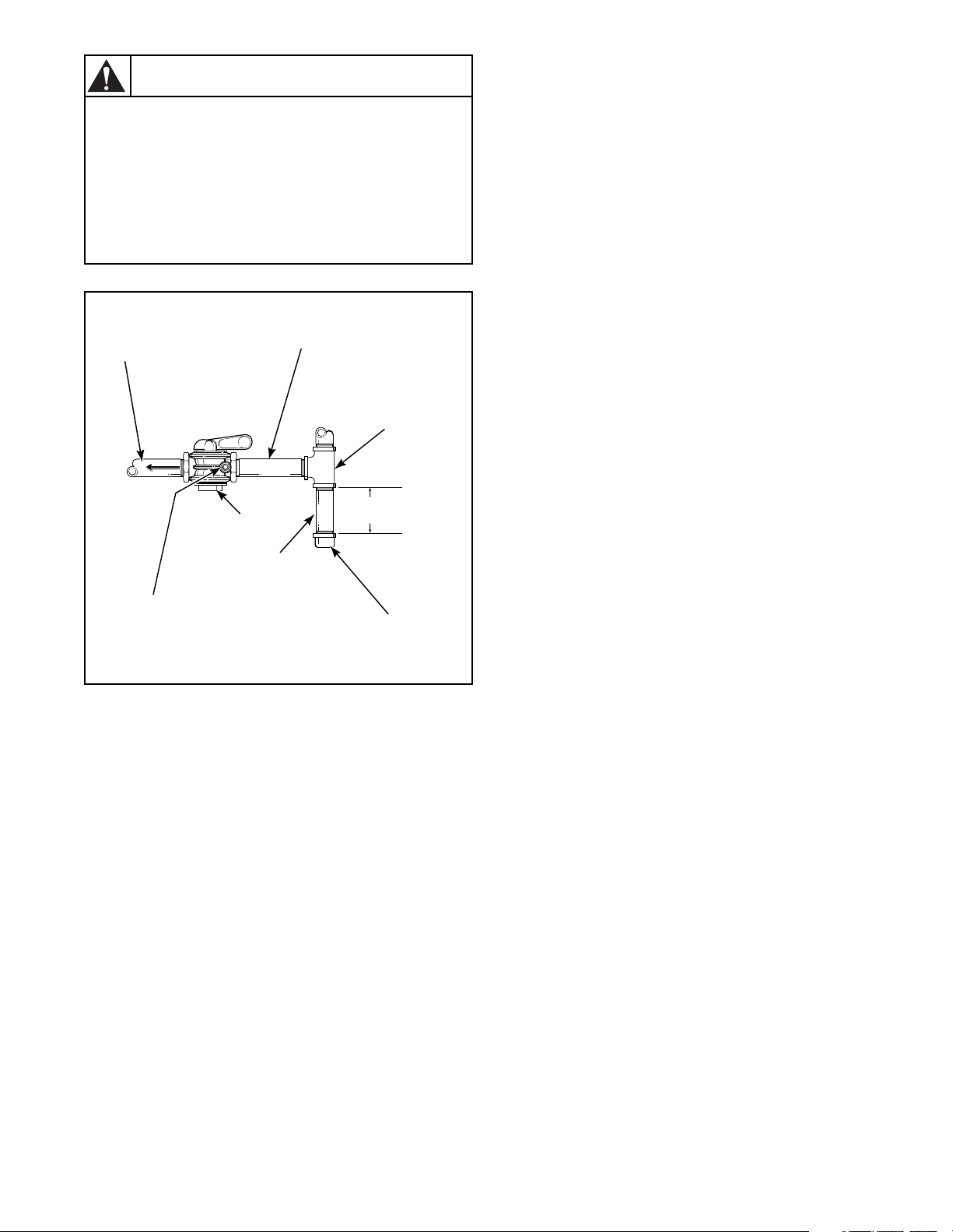
1. Refer to Figure 9 for proper steam pipe
configurations.
2. To prevent condensate draining from headers to
tumbler, piping should have a minimum 12 inch rise
(30.5 cm) above respective header. Do not make
steam connection to header with a horizontal or
downward facing tee or elbow.
3. Whenever possible, horizontal runs of steam lines
must drain, by gravity, to respective steam header.
Water pockets, or an improperly drained steam
header will provide wet steam, causing improper
operation of tumbler. If pockets or improper drainage
cannot be eliminated, install a bypass trap to drain
condensate from the low point in the steam header to
the return.
4. In both steam supply and steam return line, it is
recommended that each have a pipe union and globe
valve. This will enable you to disconnect the steam
connections and service the tumbler while your
facility is in operation.
5. Before connecting trap and check valve to tumbler,
open shut-off valve in steam supply line and allow
steam to flow through tumbler to flush out any dirt
and scale from tumbler. This will assure proper
operation of trap when connected.
6. After flushing system, install vacuum breaker, bucket
trap (with built-in strainer) and check valve. For
successful operation of tumbler, install trap 18 inches
(45.7 cm) below coil and as near to the tumbler as
possible. Inspect trap carefully for inlet and outlet
markings and install according to trap manufacturer’s
instructions. If steam is gravity returned to boiler,
omit trap but install vacuum breaker and check valve
in return line near tumbler.
PIPING RECOMMENDATIONS
1. Trap each steam coil individually. Always keep the
trap clean and in good working condition.
2. When tumbler is on the end of a line of equipment,
extend header at least 4 feet (1.2 m) beyond tumbler.
Install shutoff valve, union, check valve and bypass
trap at end of line. If gravity return to boiler, omit
trap.
3. Insulate steam supply and return line for safety of
operator and safety while servicing tumbler.
4. Keep tumbler in good working condition. Repair or
replace any worn or defective parts.
NOTE: Steam heated tumbler models are not
certified by the American Gas Association or the
Canadian Gas Association.
WARNING
The flexible steam hoses connecting the
coil outlet connections and steam traps
must have a minimum of 172 psig (pounds
per square inch gauge) (12.04 kg/sq. cm)
working pressure. A shut-off valve must
be installed downstream from each steam
trap so the condensate return line can be
isolated in event a steam trap requires
maintenance.
W064
STEAM VALVE ELECTRICAL CONNECTIONS
Refer to wiring diagram for steam valve electrical
connections in J-Box.
7. Install union and shut-off valve in return line and
make final pipe connections to return header.
28 M414545
© Copyright, Alliance Laundry Systems LLC – DO NOT COPY or TRANSMIT
Page 31

INSTALLING STEAM SOLENOID VALVE AND MAKING STEAM INLET CONNECTIONS
INSTALLING STEAM TRAP AND MAKING CONDENSATE RETURN CONNECTIONS
High pressure machines require a (constant) 80 to 100
psig (pounds per square inch gauge) (5.62 to 7.03 kg/sq.
cm) steam service for optimum operation. Low pressure
machines require a (constant) 10 to 15 psig (pounds per
square inch gauge) (.70 to 1.05 kg/sq. cm) steam service
for optimum operation. The following steps outline the
procedure for installing the steam solenoid valve and
connecting the steam service.
a. Install a manual shut-off gate valve in the condensate
return line after the steam trap for each coil.
b. Connect the steam solenoid valve to the related steam
coil inlet connection with nipples, flex hoses, unions,
and tee. Refer to Figure 9.
c. Install a gate shut-off valve in the steam supply line.
Connect the shut-off gate valve outlet to the solenoid
steam valve inlet connection. Refer to Figure 9.
WARNING
The flexible steam hoses connecting the
solenoid steam valve to the coil inlets
must have a 125 psig (pounds per square
inch gauge) (8.79 kg/sq. cm) working
pressure. A shut-off valve must be
installed upstream from the solenoid
steam valve. This way, steam can be shut
off for maintenance purposes, or in the
event the hose ruptures.
The steam solenoid valve must be
supported so minimum load is exerted on
the steam coil inlet connections.
W065
The steam trap must be installed and the coil outlet
connections must be connected to the condensate return
lines. The following steps outline the procedure for
installing the steam trap and connecting the condensate
return lines. Refer to Figure 9.
a. Connect a flexible hose to each steam coil outlet.
b. Install a strainer to the ends of each flexible hose.
c. Install a steam trap to each strainer.
IMPORTANT: Steam trap must be installed a
minimum of 10 inches (25.4 cm) below the steam coil
outlet connections.
d. Install a gate shut-off valve to each steam trap.
e. Connect to the condensate return lines.
WARNING
The flexible steam hoses connecting the
coil outlet connections and steam traps
must have a minimum of 125 psig (pounds
per square inch gauge) (8.79 kg/sq. cm.)
working pressure. A shut-off valve must
be installed downstream from each steam
trap so the condensate return line can be
isolated in event a steam trap requires
maintenance.
Each steam trap must be supported so
minimum load is exerted on the coil outlet
connection.
W066
M414545
© Copyright, Alliance Laundry Systems LLC – DO NOT COPY or TRANSMIT
29
Page 32

STEAM REQUIREMENTS STEAM DRYING TUMBLERS ONLY
NOTE: For sizing of steam lines. Piping
must also be sized accordingly for length
of runs, and number of elbows. Refer to
Table 3.
SUPPLY
RETURN
12" (30.5 cm)
RISERS
UNION
CHECK
VALVE
TRAP WITH
BUILT-IN
STRAINER
STEAM
BONNET
SOLENOID
VALVE
(Supplied with
machine)
VACUUM
BREAKER
CONDENSATE
RETURN LINE
FROM
SUPPLY LINE
CHECK
VALVE
Figure 9
TUMBLER
MODEL
STEAM PRESSURE
(PSI)
MINIMUM PIPE
DIAMETER
STEAM TRAP SIZE
(Pounds Condensate/Hour)
30CSL 7-15 3/4" (1.9 cm) 140
30CSH 80-100 3/4" (1.9 cm) 140
GATE
VALVE
T221IE3H
Table 3
30 M414545
© Copyright, Alliance Laundry Systems LLC – DO NOT COPY or TRANSMIT
Page 33

ELECTRICAL REQUIREMENTS
WARNING
To reduce the risk of electric shock, fire, explosion, serious injury or death:
• Disconnect electric power to the tumbler before servicing.
• Close gas shut-off valve to gas tumbler before servicing.
• Close steam valve to steam tumbler before servicing.
• Never start the tumbler with any guards/panels removed.
• Whenever ground wires are removed during servicing, these ground wires must be reconnected
to ensure that the tumbler is properly grounded.
WARNING
To reduce the risk of fire and electric shock, check with a qualified serviceman for proper
grounding procedures. Improper connection of the equipment grounding conductor may
result in a risk of electric shock.
To reduce the risk of fire and electric shock, if electrical supply is coming from a three
phase service, DO NOT connect a “High Leg” or “Stinger Leg” to a single phase machine.
On a three phase machine, if there is a “High Leg” or “Stinger Leg” it should be
connected to L3.
W002
W068
W069
GROUNDING INSTRUCTIONS
This tumbler must be grounded. In the event of
malfunction or breakdown, grounding will reduce the
risk of electric shock by providing a path of least
resistance for electric current. This tumbler must be
connected to a grounded metal, permanent wiring
system; or an equipment grounding conductor must be
run with the circuit conductors and connected to the
appropriate ground location.
WARNING
All electrical connections should be
made by a qualified electrician.
To reduce the risk of electrical shock, deenergize the electrical circuit being
connected to the tumbler before making
any electrical connections. Never attempt
to connect a live circuit.
W070
NOTE: To ensure protection against shock, this
tumbler MUST be electrically grounded in
accordance with the local codes, or in the absence of
local codes, with the latest edition of the National
Electrical Code ANSI/NFPA No. 70. In Canada the
electrical connections are to be made in accordance
with CSA C22.1 latest edition Canadian Electrical
Code, Part I and/or local codes. Electrical work
should be done by a qualified electrician.
CAUTION
Label all wires prior to disconnection
when servicing controls. Wiring errors
can cause improper and dangerous
operation. Verify proper operation after
servicing.
W071
M414545
© Copyright, Alliance Laundry Systems LLC – DO NOT COPY or TRANSMIT
31
Page 34

The following steps outline the procedure for connecting
the electrical service to the tumbler.
3. Check the electrical service phase sequence (three
phase only) as follows:
NOTE: The wiring diagram is supplied in material
packet in cylinder.
1. Install a circuit breaker as close to the tumbler as
possible. If more than one tumbler is being installed,
a disconnect switch or circuit breaker should be
provided for each. This will make it possible to
disconnect each tumbler for maintenance purposes.
2. Connect the conduit-encased leads to the disconnect
switch, or circuit breaker. Connect the wire leads to
the appropriately labeled terminal on the terminal
block. The ground wire must be connected to the
ground connection. Refer to Figure 10.
ELECTRICAL SERVICE
(Gas & Steam Models)
a. Energize the electrical service (on reversing
tumblers, ensure nonreversing is selected)and
momentarily start the tumbler. Check the direction
of the cylinder rotation. If the cylinder rotates
clockwise (viewed from the front), the phase
sequence is correct. If the cylinder rotates
counterclockwise, proceed with step “b”.
NOTE: On reversing tumblers, the fan motor should
also rotate clockwise (viewed from the front) on all
models.
b. Disconnect and reverse any two leads at
connections.
ELECTRICAL SERVICE
(Electric Models)
CONTACTOR
BOX
ACCESSORY
BOX
GROUND LUG
(Electric Models)
FUSES
GROUND SCREW
(Gas & Steam Models Only)
T224SE3A
Figure 10
32 M414545
© Copyright, Alliance Laundry Systems LLC – DO NOT COPY or TRANSMIT
Page 35

JUMPER CONFIGURATION INSTRUCTIONS (OPL MICRO CONTROL MODELS ONLY)
RING FERRITE INSTALLATION (GAS AND STEAM OPL MICRO CONTROL MODELS ONLY)
Changing the transformer configuration jumper is
required if any of the following apply:
• You have 208V service and are connecting a gas or
steam model rated for 208 or 240V.
• You have 415V service and are connecting a gas or
steam model rated for 380 or 415V.
To configure your 208V or 240V tumbler for 208V
operation, you must remove the 240V configuration
jumper located in the contactor box and replace it with
the 208V jumper supplied with the information packet.
This must be done prior to supplying power to machine.
Failure to install proper configuration jumper may result
in damage to sensitive electronic controls and may void
warranty.
To configure your 380V or 415V tumbler for 415V
operation, you must remove the 380V configuration
jumper located in the contactor box and replace it with
the 415V jumper supplied with the information packet.
This must be done prior to supplying power to machine.
Failure to install proper configuration jumper may result
in damage to sensitive electronic controls and may void
warranty.
The ring ferrite provided in the information packet must
be installed over the power leads during connection of
electrical service. The ferrite protects the sensitive
electronic controls from destructive electrical
disturbances which may be present on power lines to the
machine. Failure to properly install the ring ferrite may
result in damage to the electronic controls and will void
control warranty.
Installation Instructions:
1. Immediately after connection of power leads and
before applying power to machine, locate each of the
incoming service leads including ground.
2. Snap the ring ferrite closed over all of the service
leads inside of the contactor box as shown. It is
important that the ferrite ring be installed inside the
contactor box as shown. Do not install the ferrite
outside of the box or other area. Make sure that
service leads are in the center of the ferrite before
closing the ring so not to pinch or damage leads.
CONTACTOR
BOX
JUMPER
Figure 11
FERRITE
RING
T225SE1A
M414545
© Copyright, Alliance Laundry Systems LLC – DO NOT COPY or TRANSMIT
33
Page 36

ELECTRICAL REQUIREMENTS For 28" wide Tumblers
NOTE: Minimum wire sizes are obtained from Canadian Electrical Code and are intended for use as a guideline
only. Electrical connections should be made only by a qualified electrical contractor in accordance with all
applicable local and national requirements.
NOTE: DO NOT use aluminum wire.
Heat Source
Gas 120/60/1 L1, Neutral, and ground
Gas 208-240/60/1 L1, L2, Neutral, and ground
Gas 240/50/1 L1, Neutral, and ground
Gas 120/50/1 L1, Neutral, and ground
Electric 208/60/1 L1, L2, and ground
Electric 240/60/1 L1, L2, and ground
Electric 240/50/1 L1, Neutral, and ground
Electric 208/60/3 L1, L2, and ground
Electric 240/50/3 L1, L2, L3, and ground
Electric 240/60/3 L1, L2, L3, and ground
Electric 380/50/3 L1, L2, L3, Neutral, and ground
Electric 415/50/3 L1, L2, L3, Neutral, and ground
Electric 480/60/3 L1, L2, L3, and ground
Amp Rating 104 AMP 92 AMP 62 AMP 55 AMP 27 AMP 91 AMP 55 AMP 34 AMP 31 AMP
Circuit Breaker 125 AMP 100 AMP 70 AMP 60 AMP 30 AMP 100 AMP 60 AMP 40 AMP 35 AMP
Poles 223332333
Minimum Wire Size
Per Canadian Elec.
Code C22.1
Electrical Specs
ELECTRIC DRYING TUMBLERS
208V
60 HZ
1 PH
1 AWG 2 AWG 4 AWG 6 AWG 10 AWG 2 AW G 6 AWG 8 AWG 8 AWG
240V
60 HZ
1 PH
208V
60 HZ
3 PH
Wires Required and Terminal Block Connections
Table 4
240V
60 HZ
3 PH
480V
60 HZ
3 PH
240V
50 HZ
1 PH
240V
50 HZ
3 PH
380V
50 HZ
3 PH
415V
50 HZ
3 PH
Table 5
GAS DRYING TUMBLERS
120V 1 Phase
60 Hz.
Minimum Wire Size Per
Canadian Elec. Code C22.1
Disconnect Switch 15 AMP
Fusetron 15 AMP
Circuit Breaker 15 AMP 15 AMP 15 AMP 15 AMP
No. of Poles 1222
34 M414545
© Copyright, Alliance Laundry Systems LLC – DO NOT COPY or TRANSMIT
14 AWG 16 AWG 16 AWG 14 AWG
208/240V 1 Phase
60 Hz.
USE CIRCUIT BREAKER ONLY
Table 6
240V 1 Phase
50 Hz.
120V 1 Phase
30 Hz.
Page 37

ELECTRICAL REQUIREMENTS For 31.5" wide Tumblers
NOTE: Minimum wire sizes are obtained from Canadian Electrical Code and are intended for use as a guideline
only. Electrical connections should be made only by a qualified electrical contractor in accordance with all
applicable local and national requirements.
NOTE: DO NOT use aluminum wire.
Heat Source Serial Plate Voltage
Steam CSL 120V/60Hz/1ph L1, Neutral and ground * 20 Amps 1 12 AWG
Gas & CSH 120V/60Hz/1ph L1, Neutral and ground * 15 Amps 1 14 AWG
Gas & Steam 208 or 240V/60Hz/1ph L1, L2 and ground * 15 Amps 2 14 AWG
Gas & Steam 230-240V/50Hz/1ph L1, Neutral and ground * 15 Amps 1 14 AWG
Gas & Steam 208 or 240V/60Hz/3ph L1, L2, L3, and ground * 15 Amps 3 14 AWG
Gas & Steam 380 or 415V/50Hz/3ph L1, L2, L3, and ground * 15 Amps 3 14 AWG
Gas & Steam 460-480V/60Hz/3ph L1, L2, L3, and ground * 15 Amps 3 14 AWG
Electric 208V/60Hz/1ph L1, L2, and ground 104 Amps 125 Amps 2 0 AWG
Electric 240V/60Hz/1ph L1, L2, and ground 92 Amps 100 Amps 2 2 AWG
Electric 240V/50Hz/1ph L1, Neutral and ground 90 Amps 100 Amps 1 2 AWG
Electric 208V/60Hz/3ph L1, L2, L3, and ground 62 Amps 70 Amps 3 4 AWG
Electric 240V/60Hz/3ph L1, L2, L3, and ground 55 Amps 60 Amps 3 4 AWG
Electric 240V/50Hz/3ph L1, L2, L3, and ground 53 Amps 60 Amps 3 4 AWG
Electric 380V/50Hz/3ph L1, L2, L3, and ground 33 Amps 40 Amps 3 8 AWG
Electric 415V/60Hz/3ph L1, L2, L3, and ground 30 Amps 35 Amps 3 8 AWG
Electric 480V/60Hz/3ph L1, L2, L3, and ground 28 Amps 35 Amps 3 8 AWG
* Current Ratings vary slightly depending on model, see nameplate.
Terminal Block
Connections Required
Rated
Current
Breaker
Rating
Breaker
Poles
Recommended
Wire Size
Table 7
M414545
© Copyright, Alliance Laundry Systems LLC – DO NOT COPY or TRANSMIT
35
Page 38

ACCESSORY TIMING CAM INSTALLATION (Coin Meter Models)
The tumbler is shipped with two accessory cams which
allow you to change your vending times.
The coin slide tumbler accumulator will have a 60 minute
timer motor. The accumulator will operate with a two pin
cam (30 minutes). The cams furnished with the tumbler
will be three pin (20 minutes) and four pin (15 minutes).
The 25¢ meter will have a 60 minute timer motor. Refer
to Table 8.
No. of Pins in Cam Cycle Length (Minutes)
6
5
4
10
12
15
Table 8
Cams that allow other timer increments are available
through your distributor.
To figure time increments, use this formula: Timer Motor
Speed (60) divided by number of pins on cam = Cycle
Length (minutes). Cams are available with 1 to 12 pins.
Example: 60
÷ 5 (Pin cam) = 12 minute cycle.
INSTALLATION OF NEW TIMING CAM
1. Insert drive into timing cam with wide prong in wide
hole of cam.
2. Position timing cam and drive fork over the timer
shaft, aligning the timer flat with the drive fork and
the “V” notch with one of the ratchet teeth.
3. Press timing cam down firmly to seat timing cam
onto the motor shaft.
LINE UP NOTCH
TO CLEAR RATCHET
TOOTH
LIFT GENTLY
WITH NARROW
BLADE
REMOVAL OF EXISTING TIMING CAM
1. Rotate cam by hand until “V” notch lines up beneath
the ratchet tooth. Refer to Figure 12.
2. Insert narrow screwdriver under nylon cam, close to
the clock shaft. Lift gently off shaft. Make sure that
pressure is directed upward and that the “V” notch
clears the ratchet tooth.
Figure 12
4. Remove all accumulated time by turning cam
counterclockwise until switch shuts off. Apply
moderate clockwise pressure to fully seated timing
cam and drive against the timing motor shaft. Meter
must be advanced electrically for one cycle before an
accurate measure of time can be made.
36 M414545
© Copyright, Alliance Laundry Systems LLC – DO NOT COPY or TRANSMIT
Page 39

PRELIMINARY OPERATING CHECKS
1. Remove or open all panels and check accessible
bolts, nuts, screws, terminals and fittings for
tightness.
2. Check V-belt tension and adjust if necessary. Refer to
appropriate paragraphs in Section IV.
3. Steam tumblers: Open the steam service shut-off
valves.
4. After performing the previous checks, start the
tumbler by pressing START (hold for approximately
three seconds). Release the start button and open the
cylinder door. The cylinder should stop rotating
within seven seconds after the door is opened a
maximum of two inches (5.01 cm) plus or minus ¹⁄₄
inch (.63 cm). If it does not, adjust the loading door
interlock. Refer to the appropriate paragraph in
Section IV.
5. Gas tumblers: Start the tumbler and check the burner
flame. Adjust the gas inlet shutter as required. Refer
to the appropriate paragraph in Section IV.
IMPORTANT: The one wire igniter Instant
Electronic Ignition system will attempt to light the gas
by sparking for approximately 15 seconds (5 seconds
for 2 wire igniters). If gas ignition does not take place
within 15 seconds (5 seconds for 2 wire igniters) the
Instant Electronic Ignition control will go into safety
lockout and the valve will no longer open until Instant
Electronic Ignition control is reset. To reset Instant
Electronic Ignition control, remove power from
control by opening and closing the tumbler door. If
condition persists, check, that the gas shut-off valve is
in “on” position and that the gas service is properly
connected. If condition still persists, remove tumbler
from service.
6. Load the cylinder with a full load of clothes or clean
rags and run to remove oil or dirt from cylinder.
7. Gas and electric tumblers: Check the airflow switch
operation by opening the lint panel. The heating
systems should shut off when the lint panel is opened
a maximum of 1-1/2 inches (3.81 cm).
WARNING
The tumbler must not be operated if the
airflow switch does not operate properly.
Faulty airflow switch operation may cause
an explosive gas mixture to collect in the
tumbler.
W072
The airflow switch operation may be affected by shipping
tape still in place, lack of make-up air, or an obstruction
in the exhaust duct. These should be checked and the
required corrective action taken before attempting to
adjust the airflow switch. To adjust the airflow switch
refer to appropriate paragraph in Section IV.
M414545
© Copyright, Alliance Laundry Systems LLC – DO NOT COPY or TRANSMIT
37
Page 40

FINAL OPERATING CHECKS
OPL MICRO CONTROL TUMBLER
Refer to OPL micro-control section to check control for
proper operation.
MANUAL DUAL TIMER TUMBLER
Refer to Figure 13.
1. Set the TEMPERATURE selector to the desired
temperature, and set the DRYING and COOLING
selectors to maximum.
2. Press the PUSH-TO-START button in and hold it in
for approximately three seconds. The motor will
start, the heat system will come on and the DRYING
indicator will light.
3. During the drying period the DRYING selector
rotates counterclockwise. When the DRYING
selector reaches “0” the heat system will shut off, the
DRYING indicator will go out and the COOLING
indicator will light.
During the cooling period the COOLING selector rotates
to the left. When the COOLING selector reaches “0” the
motor will stop and the COOLING indicator will go out
indicating the end of the cycle.
COIN-OPERATED TUMBLER
Refer to Figure 14.
1. Set the TEMPERATURE selector to the desired
temperature.
2. Insert required number of coins in the coin slot and
turn the knob fully clockwise and release it. The
RUN indicator (option) will light.
For Coin Slide Models — Place required number of
coins in coin slide and push slide in as far as possible,
then release.
3. Press the PUSH-TO-START button in and hold it in
for approximately three seconds. The motor will start
and the heat circuit will come on.
4. An automatic preset 2-1/2 minute cool-down period
occurs near the end of the cycle. During this period
the heat system is off and encompassing air circulates
through the load to cool it.
5. When the coin metered time expires, the cycle is
completed.
38 M414545
© Copyright, Alliance Laundry Systems LLC – DO NOT COPY or TRANSMIT
Page 41

TEMPERATURE
SELECTOR
MANUAL DUAL TIMER
DURABLE PRESS CONTROL PANEL
TEMPERATURE
HIGH LOW
MED
PUSH TO START
COOLING
INDICATOR
COOLING
10
5
DRYING
INDICATOR
DRYING
25
20
15
0
15
30
0
5
10
T020IE3A
PUSH-TO-START
BUTTON
Figure 13
TEMPERATURE
SELECTOR
HIGH
*SINGLE COIN-OPERATED
COTTON
DURABLE PRESS CONTROL PANEL
PUSH-TO-START
BUTTON
* DUAL COIN OPERATED PANELS HAVE SLOTS FOR TWO COINS.
EACH COIN OPERATES THE TUMBLER FOR A SPECIFIC TIME.
Figure 14
RUN
INDICATOR
TEMPERATURE
MED
MIXED
PUSH TO START
COOLING
TIMER
SELECTOR
LOW
PERMA
PRESS
DRYING
TIMER
SELECTOR
SINGLE AND DUAL COIN
METER COIN SLOT AND KNOB
T019IE3A
M414545
TEMPERATURE
SELECTOR
PUSH-TO-START
BUTTON
© Copyright, Alliance Laundry Systems LLC – DO NOT COPY or TRANSMIT
RUN
INDICATOR
COIN
SLIDE
T004IE3A
Figure 15
39
Page 42

Notes
40 M414545
© Copyright, Alliance Laundry Systems LLC – DO NOT COPY or TRANSMIT
Page 43

Section IV
Adjustments
MAIN GAS BURNER AIR SHUTTER All Gas Models
NOTICE: Air inlet shutters on the burner must be
adjusted so sufficient air is metered into the system
for proper combustion and maximum efficiency.
Before adjusting the inlet shutters be sure that all lint
is removed from lint compartment and lint screen.
Air shutter adjustments will vary from location to
location and will depend on the vent system, number of
units installed, make-up air and line gas pressure.
Opening the shutter increases the amount of primary air
supplied to the burner while closing the shutter decreases
the primary air supply. Adjust air shutter as follows:
1. Open the access panel.
2. Start the tumbler and check the flame pattern. Correct
air and gas mixture is indicated if the flame pattern is
primarily blue, with small yellow tips, and bends to
the right of the heater section. Too little air is
indicated if the flame is yellow, lazy and smokey.
Refer to Figure 16.
PROPER
AIR FLOW
INSUFFICIENT
AIR FLOW
3. To adjust the air shutter, loosen air inlet shutter
adjusting screw. Refer to Figure 16.
4. Open or close air shutter as necessary to obtain
proper flame intensity.
5. After air shutter is adjusted for proper flame, tighten
air shutter adjusting screw securely. Control panel
may have to be removed temporarily to loosen air
shutter screws to adjust shutter.
6. If the shutter is correctly adjusted, but the flame
pattern is straight up, insufficient primary air is
flowing through the tumbler and airflow switch is
improperly set. A flame pattern that flares to the right
and left indicates no air is flowing through the
tumbler. Refer to Figure 16.
NO AIR FLOW
M414545
AIR SHUTTER
ADJUSTING
SCREWS
T048SE3A
AIR SHUTTER
ADJUSTING
SCREWS
T047SE3A
Figure 16
© Copyright, Alliance Laundry Systems LLC – DO NOT COPY or TRANSMIT
T049SE3A
AIR SHUTTER
ADJUSTING
SCREWS
41
Page 44

AIRFLOW SWITCH For Gas and Electric Tumblers
The airflow switch (located on the rear of tumbler) is set at
the factory for proper operation. Refer to Figure 17. Steam
models do not have an airflow switch. However, if there is
a problem with the switch, it should be adjusted as follows:
NOTICE: Control panel must be in place and access
door closed before attempting to adjust airflow
switch.
IMPORTANT: Airflow switch disc must remain
closed during operation. If it opens and closes during
the drying cycle, this indicates insufficient airflow
through the tumbler. If switch remains open, or pops
open and closed during the cycle, the heating system
will shut off. The cylinder and fan will continue to
operate even though the airflow switch is
malfunctioning.
WARNING
To reduce the risk of fire, airflow switch
operation may be affected by a clogged
lint screen, lack of make-up air,
obstructions in the vertical recirculation
stack or in the customer installed main or
collector ducts. These conditions must
be checked and necessary corrections
made before adjusting airflow switch.
Always adjust airflow at installation.
W073
The airflow switch operation is controlled by the
counterweight position in the shaft. Moving the
counterweight either increases or decreases airflow
switch sensitivity. The counterweight should be adjusted
so the airflow will force the disc away from the cabinet
when the lint panel is opened 6 inches (15.24 cm) with a
full load. Adjust the airflow switch as follows:
1. Load the tumbler. This adjustment is much faster to
make with one person opening lint panel in front and
another adjusting the counterweight in the rear of
tumbler.
2. Start the tumbler. Open the lint panel 6 inches
(15.24 cm). The airflow disc should move away
from the cabinet, opening the switch contacts and
shutting off the heat system. This indicates proper
operation and proper adjustment.
3. If switch is not opening as described in step “2”, it
should be adjusted so it is MORE sensitive. Depress
the spring clip and move counterweight toward disc.
Retest by opening lint panel and continue moving
counterweight toward disc until switch operates as
described in step “2”.
4. If switch opens BEFORE lint panel is opened the
proper distance, step “2”, it should be adjusted so it
is LESS sensitive. Depress the spring clip and move
counterweight away from the disc. Retest by opening
lint panel and continue moving counterweight away
from disc until switch operates as described in step
“2”.
AIR FLOW
SWITCH
COUNTERWEIGHT
MOUNTING
BRACKET
SWITCH
LEVER
DISC
SPRING
CLIP
REAR
PANEL OF
TUMBLER
AIR FLOW
SWITCH
VANE
LEVER
ARM
DISC
SWITCH
ADJUSTING
SCREWS
SCREW
SWITCH
LEVER
SPRING
CLIP
COUNTERWEIGHT
T041IE3A
Figure 17
42 M414545
© Copyright, Alliance Laundry Systems LLC – DO NOT COPY or TRANSMIT
Page 45

LOADING DOOR SWITCH
The door switch should be adjusted so the cylinder stops
when door is opened two inches (5.08 cm), plus or minus
1/4 inch (.63 cm). This switch is a normally open switch
and is closed by the interlock rod when the door is closed.
If adjustment is required, proceed as follows. Refer to
Figure 18.
1. Close door and start tumbler, slowly open loading
door. Cylinder and heat system should shut off when
door is open two inches (5.08 cm) plus or minus 1/4
inch (.63 cm).
2. Slowly close loading door. When door is two inches
from being fully closed, the tab should contact the
interlock rod and depress it enough to operate the
switch arm closing the switch with an audible
“click”.
3. If interlock rod does not depress enough to operate
the switch, bend tab on loading door OUTWARD one
eighth inch (.32 cm) and repeat steps “1” and “2”.
Bend tab outward an additional 1/8, inch (.32 cm) if
required to obtain proper rod movement and switch
operation.
4. If proper operation is not obtained by procedure
outlined in step “3”, unlock and open top panel and
remove control panel. Loosen the two adjusting
screws holding the switch to the bracket and move
switch 1/8, inch (.32 cm) toward the front of the
switch bracket and retighten the screws. Repeat steps
“1” and “2”. If switch and rod still do not have
sufficient movement, move switch forward an
additional 1/8 inch (.32 cm).
SWITCH
ARM
SWITCH
BRACKET
ADJUSTING
SCREWS
INTERLOCK
ROD
Figure 18
DOOR
SAFETY
SWITCH
TAB
T249IE1A
M414545
© Copyright, Alliance Laundry Systems LLC – DO NOT COPY or TRANSMIT
43
Page 46

LOADING DOOR STRIKE
The door strike must be adjusted to have sufficient
tension to hold loading door closed against force of load
tumbling against it. Proper adjustment is when 8 to 15
pounds (35.6 N - 66.7 N) pull is required to open door.
If adjustment is required, proceed as follows. Refer to
Figure 19.
To adjust, open door, loosen jam nut and turn door strike
screw in or out as required. Retighten jam nut.
DOOR
STRIKE
ACORN
NUT
DOOR
LATCH
Figure 19
T048IE1A
44 M414545
© Copyright, Alliance Laundry Systems LLC – DO NOT COPY or TRANSMIT
Page 47

WARNING
To reduce the risk of electric shock, fire, explosion, serious injury or death:
• Disconnect electric power to the tumbler before servicing.
• Close gas shut-off valve to gas tumbler before servicing.
• Close steam valve to steam tumbler before servicing.
• Never start the tumbler with any guards/panels removed.
• Whenever ground wires are removed during servicing, these ground wires must be reconnected
to ensure that the tumbler is properly grounded.
CHAIN DRIVE
Nonreversing Models
Refer to Figure 20.
W002
Proper tension is when the belt can be depressed
approximately 1/2 inch (1.27 cm) by applying light
thumb pressure at a point midway between the cylinder
sprocket and the idler sprocket.
IMPORTANT: After a tumbler has been in operation
over an extended period of time, a “HIGH POINT”
will develop on the cylinder drive sprocket through
use and wear. Turn the sprocket manually with drive
chain in place until this “high point” is at the top
center. The “high point” can be found by noticing
increased chain tension while slowly rotating the
cylinder sprocket manually.
BELT DRIVE
Nonreversing Models
Refer to Figure 21.
Proper tension is when the drive V-belt can be depressed
approximately 1/2 inch (1.27 cm) by applying light
thumb pressure at a point midway between the sheave
and motor pulley.
1. Remove guard from rear of tumbler.
1. Remove guard from rear of tumbler.
2. To adjust chain tension, loosen acorn nut holding
idler sprocket to housing.
3. Move idler sprocket left or right until proper chain
tension is reached, then retighten the acorn nut.
4. Replace the guard on rear of tumbler.
2. To adjust belt tension, loosen idler housing bolts
holding idler housing assembly to the housing
support.
3. Position housing assembly by turning adjusting bolt
until proper belt tension is reached, then retighten
idler housing bolts.
M414545
4. Replace the guard on rear of tumbler.
© Copyright, Alliance Laundry Systems LLC – DO NOT COPY or TRANSMIT
45
Page 48

BELT DRIVE
Reversing Models
Refer to Figure 22.
Proper tension is when the drive belt can be depressed
approximately 1/2 inch (1.27 cm) by applying light
thumb pressure (approximately 5 pounds) at a point
midway between the sheave and motor pulley.
Proper tension is when each cylinder belt can be
depressed approximately 3/16 inch (.48 cm) by applying
light thumb pressure (approximately 5 pounds) at a point
midway between the sheave and the idler.
1. Remove guard from rear of tumbler.
2. To adjust cylinder belt tension, loosen idler housing
bolts holding idler housing assembly to the housing
support.
3. Position housing assembly by turning adjusting bolt
until proper belt tension is reached, then retighten
idler housing bolts.
NOTE: Adjusting the cylinder belt tension will
change the drive belt tension. Drive belt tension must
also be adjusted.
4. Loosen the locking bolt.
5. Loosen the adjusting nut and use the adjusting screw
to move the motor up or down.
6. Once proper belt tension is reached, retighten the
adjusting nut and locking bolt.
7. Replace the guard on rear of tumbler.
46 M414545
© Copyright, Alliance Laundry Systems LLC – DO NOT COPY or TRANSMIT
Page 49

NONREVERSING
CHAIN DRIVE MODELS
SHEAVE
ONE HALF INCH
(1.27 cm)
DEFLECTION
CYLINDER
DRIVE CHAIN
WARNING! DO NOT
OPERATE WITHOUT
GUARDS IN PLACE.
CYLINDER
SPROCKET
IDLER
SPROCKET
JAMNUT
DRIVE
SPROCKET
BELT ADJUSTING
BOLT AND NUT
ONE HALF
INCH
(1.27 cm)
DEFLECTION
V-BELT
MOTOR
PULLEY
NOTE: Tumbler is shown with guards removed for ilustration purposes only.
Never operate the tumbler with the guards removed.
IDLER
HOUSING
GUIDE
RAIL
GUIDE RAIL
WASHER
GROUND WIRE
(Green)
TMB1966N
M414545
Figure 20
© Copyright, Alliance Laundry Systems LLC – DO NOT COPY or TRANSMIT
47
Page 50

NONREVERSING
BELT DRIVE MODELS
POLY
V-BELT
(Poly V-belt is
self-adjusting)
IDLER
HOUSING
BOLTS
(2)
ADJUSTING
BOLT
DRIVE
V-BELT
IDLER
HOUSING
ASSEMBLY
T234IE3B
Figure 21
48 M414545
© Copyright, Alliance Laundry Systems LLC – DO NOT COPY or TRANSMIT
Page 51

REVERSING MODELS
DRIVE
BELT
ADJUSTING
BOLT
(Not Shown)
LOCKING
BOLT
ADJUSTING
NUT
ADJUSTING
SCREW
IDLER
HOUSING
BOLTS
(2)
CYLINDER
BELTS
IDLER
HOUSING
ASSEMBLY
T322IE3A
M414545
Figure 22
© Copyright, Alliance Laundry Systems LLC – DO NOT COPY or TRANSMIT
49
Page 52

Notes
50 M414545
© Copyright, Alliance Laundry Systems LLC – DO NOT COPY or TRANSMIT
Page 53

Section V
Operating Instructions
WARNING
To reduce the risk of fire:
• DO NOT DRY articles containing foam rubber
or similarly textured rubberlike materials.
• DO NOT DRY plastics, anything containing
wax or chemicals such as mops and
cleaning cloths, or anything dry-cleaned at
home with a dry-cleaning solvent.
• DO NOT TUMBLE fiberglass curtains and
draperies unless the label says it can be
done. If they are dried, wipe out the cylinder
with a damp cloth to remove particles of
fiberglass.
W076
WARNING
To reduce the risk of serious injury, open
tumbler door and allow cylinder to stop
before cleaning lint screen. Do not operate
without lint panel in place.
W077
ALWAYS FOLLOW THE FABRIC CARE
INSTRUCTIONS SUPPLIED BY THE GARMENT
MANUFACTURER.
The following steps outline the procedure for operating a
tumbler through a complete drying cycle.
MANUAL DUAL TIMER TUMBLER
1. Energize the electrical circuit to the tumbler at the
disconnect switch or the circuit breaker.
2. Open the lint panel and check for any accumulated
lint on lint screen. Close panel tightly against tumbler
frame and lock panel securely.
3. Open the loading door and load the cylinder with
laundry. Overloading will result in excessive drying
time, wrinkled laundry, and wear to cylinder
bearings.
4. Set the TEMPERATURE selector at HIGH (cotton
load) (190°F, 88 °C) , MEDIUM (mixed load) (162°F,
72°C), LOW (Permanent Press) (140°F, 60°C), or
anywhere between these settings. The type of fabric
being dried will determine the setting.
5. Set the DRYING selector for the number of minutes
desired.
6. Set the COOLING selector for the number of
minutes desired.
7. Press the PUSH-TO-START button in and hold it in
for approximately three seconds. This starts the
tumbler cycle.
IMPORTANT: If the loading door is opened during
the cycle, the heating system will shut off and the
motor will stop. To restart the cycle, door must be
closed and the PUSH-TO-START button must be
pressed in and held for approximately three seconds.
M414545
8. When the cycle is completed, open door and remove
the laundry.
© Copyright, Alliance Laundry Systems LLC – DO NOT COPY or TRANSMIT
51
Page 54

COIN-OPERATED TUMBLER
1. Energize the electrical circuit to the tumbler at the
disconnect switch or the circuit breaker.
2. Open the lint screen panel and check for any
accumulated lint on lint screen. Close panel tightly
against tumbler frame and lock panel securely.
3. Open the loading door and load the cylinder with
laundry. Overloading will result in excessive drying
time, wrinkled laundry, and wear to cylinder
bearings.
4. Set the TEMPERATURE selector at HIGH (190ºF /
87.5ºC), MEDIUM (162ºF / 72ºC), LOW (140ºF /
60ºC), or anywhere between these settings. The type
of fabric being dried will determine the setting.
5. Coin Drop Models
Insert the required number of coins in the coin slot,
turn the knob to the right and release it.
Coin Slide Models
Insert the required number of coins in the coin slide,
push coin slide mechanism in completely and then
release it.
Electronic Control Models
Refer to Electronic Control Supplemental manual
provided with tumbler.
IMPORTANT: If the loading door is opened during
the cycle, the heating system will shut off and the
motor will stop. However, the timer will continue to
run. To restart the cycle, the door must be closed and
the PUSH-TO-START button must be pressed in and
held for approximately three seconds.
6. When the cycle is completed, open door and remove
the laundry.
52 M414545
© Copyright, Alliance Laundry Systems LLC – DO NOT COPY or TRANSMIT
Page 55

COOLING
INDICATOR
DRYING INDICATOR
PUSH-TO-START
BUTTON
SELECTOR
PUSH
START
COOLING
TIMER
TO
COOLING
10
5
Figure 23
REVERSING OPERATION
This tumbler is equipped with a second motor and
additional controls to reverse the direction of the cylinder
rotation. The main reason for this option is to prevent
tangling of large pieces and minimize wrinkling.
REVERSE CONTROL SWITCH
DRYING
15
0
50
40
30
20
60
0
10
DRYING
TIMER
SELECTOR
T216IE3D
IMPORTANT: After any electrical maintenance is
done, make sure that the blower motor is turning
clockwise as viewed from the front of the tumbler.
Then set the reverse control switch to “non-
reversing” and note that the cylinder turns constantly
clockwise as viewed from the front of the tumbler. If
not, interchange L1 and L2 power leads to the reverse
drive motor.
A simple “on-off” switch is placed in the control panel
area so the operator can choose reversing or nonreversing
operation. The switch is wired into the reverse control
time circuit in such a way that the cylinder will always
turn clockwise (as viewed from the front of the dryer)
when the reverse control switch is actuated for
“nonreversing” operation. If the cylinder is turning in the
wrong direction when the switch is actuated, it will
continue for a few seconds and then start up in the proper
direction.
M414545
© Copyright, Alliance Laundry Systems LLC – DO NOT COPY or TRANSMIT
53
Page 56

ELECTRONICALLY CONTROLLED OPL TUMBLER
INTRODUCTION
Drying can be done automatically or by time dry. When
drying automatically, the tumbler stops drying when
laundry reaches the factory set or programmed dryness
level and starts cool down. When time drying, the
tumbler stops drying when programmed time ends and
starts cool-down.
Special Cycle allows user to specify the number of
heating cycles and specify temperature from 80°F (27°C)
to 180°F (82°C) for all heat cycles.
Special Time allows user to specify temperature from
80°F (27°C) to 180°F (82°C) for all heat cycles.
Both automatic and time dry have factory-set cycles, but
other cycles can also be created. Frequently used cycles
can be saved in the control's memory as Custom cycles.
Refer to Figure 25.
A drying instructions chart is included for recording
selections and settings for various load types. Refer to
Figure 31.
In all cycles, except No Heat, Wrinkle-Free begins when
Cool Down ends. During Wrinkle-Free, the tumbler
alternately stops for 2-1/2 minutes and then runs without
heat for 2-1/2 minutes until door is opened or 60 minutes
has elapsed.
All pads can be pressed in any sequence without
damaging control or tumbler. To stop the tumbler at any
time, open the door or press STOP/RESET. The window
display will flash. Press STOP/RESET twice (within 3
seconds) to end the cycle and reset the control to idle
status. Refer to Figure 24.
NOTE: Not all tumblers will have reversing option.
OPL Micro Control Panel
Figure 24
54 M414545
© Copyright, Alliance Laundry Systems LLC – DO NOT COPY or TRANSMIT
Page 57

Figure 25
M414545
© Copyright, Alliance Laundry Systems LLC – DO NOT COPY or TRANSMIT
55
Page 58

STATUS LIGHTS, SIGNAL AND REVERSING
DOOR OPEN Lights when door is open.
Note: Display window also flashes.
DRYING Lights when laundry is drying.
COOL DOWN Lights when laundry is cooling.
CUSTOM Lights when a Custom cycle is pro-
grammed, recalled or running.
SIGNAL When lit, the signal will sound when
the laundry is ready for removal.
The signal has three loudness levels.
These can be set anytime the control
is activated. Pressing the SIGNAL
pad once produces the softest tone.
Additional presses produce louder
tones. The fourth press turns tone
and light off. The loudness level
selected is for all cycles until
changed.
When the signal is on and any key
pad is pressed, it sounds at the
selected level to confirm the pad was
properly pressed.
REVERSING When lit, the cylinder will rotate
(For Reversing in one direction for 25 seconds,
Models only) pause for 6 seconds, then rotate in
opposite direction for 25 seconds.
This sequence will repeat until the
selected cycle ends. To turn Reversing option off, press the REVERSING pad. (Any time reversing pad is
pressed, the cylinder will pause for 6
seconds.)
DRYING LAUNDRY
1. LOAD TUMBLER –
Open loading door. Shake out laundry and place in
tumbler.
2. CLOSE DOOR –
Tumbler will not operate with open door.
WARNING
To reduce the risk of bodily injury, the
tumbler stops tumbling when the door is
opened. Do not use the tumbler if it does
not stop tumbling when the door is
opened or starts tumbling without
pressing the START pad. Remove the
tumbler from use and call for service.
W078
NOTE: Do not press directly on lights or the center of
pad. For proper selection, press on pad slightly to the
right of center.
STATUS Lights
Figure 26
56 M414545
© Copyright, Alliance Laundry Systems LLC – DO NOT COPY or TRANSMIT
Page 59

3. SELECT FABRIC TYPE –
Press an ON/SELECT pad to select a temperature.
HIGH, MEDIUM, MEDIUM LOW, LOW or NO
HEAT for items that should not be dried with heat. A
light to the left of the selected pad lights up.
AC:** will be displayed when tumbler is in Auto
Cool Down. Typical cool down times for fabric
selections are preset. Refer to Table 9. The cool
down time can only be altered before cycle is
started. To alter cool down time press the COOL
DOWN pad and then press the MORE or LESS
pad (when cool down time is altered, TC:** will
be displayed). For 1 minute changes, press pad
and release. For 5 minute changes, press pad and
hold. Cooling time can be from 1 to 39 minutes.
To return to the Auto Cool Down, press MORE or
LESS pad until AC:** is displayed.
ON/SELECT Pads
Figure 27
4. SELECT CYCLE
(AUTOMATIC, TIME DRY OR CUSTOM)
A. Automatic Dry and Condition
When a temperature is selected, “A0:00” will
appear in the display window. Press START to
start the tumbler. “A*:**” will appear in the
display window. The first “*” is the selected
dryness level (dryness levels less than zero will
appear as “-*”), and the “:**” is the elapsed time.
The degree of dryness can be altered. Use the
MORE pad, or the LESS pad, to increase or
decrease dryness level.
NOTE: Dryness level can only be altered prior to the
end of the first heat cycle.
When clothes reach selected dryness level, Cool
Down begins. “AC:**” will appear in the display
window. “:**” is the elapsed Cool Down time.
When Cool Down ends, tumbler automatically
goes into wrinkle-free and “Lr” (Load Ready)
will appear in the display.
DRYNESS Pads
Figure 28
Use the CONDITION pad for items to be left
damp for ironing. “Cn:00” will replace “A0:00” in
the display.
Auto Cool Down ends when either a preset
temperature or a preset time is reached. Refer to
Table 9.
Fabric Preset Temp Preset Time
COTTONS 100° F, 38° C5 MIN
PERM PRESS 90° F, 32° C8 MIN
MIXED 90° F, 32° C5 MIN
DELICATES 90° F, 32° C5 MIN
Automatic Cool Down Temperatures and Times
Table 9
M414545
© Copyright, Alliance Laundry Systems LLC – DO NOT COPY or TRANSMIT
57
Page 60

B. Time Dry and No Heat
After fabric selection, press the TIME pad. Refer
to Figure 29.
TIME DRY Pads
Figure 29
A preset drying time, “Td:**” will replace
“A0:00” in the display. This time can be changed
by pressing the MORE or LESS pads. For 1
minute changes, press pad and release. For 5
minute changes, press pad and hold. Maximum
drying time allowed is 60 minutes.
Cycles Preset Time Range
COTTONS 35 Min 1-60 Min.
PERM PRESS 20 Min 1-60 Min.
MIXED 15 Min 1-60 Min.
DELICATES 30 Min 1-60 Min.
NO HEAT 20 Min. 1-60 Min.
To start the cycle, press START. The total drying
time plus cool down time will display. During the
cycle, remaining time displays.
NO HEAT is a time dry cycle only. When NO
HEAT is pressed, a 20 minute preset time will
display. This can be changed from 1 minute to 60
minutes by pressing the MORE or LESS pads
before pressing START. The COOL DOWN pad
does not work in NO HEAT cycles.
C. Special Cycle Mode
This allows the user to select the number of times
the tumbler will cycle from heat-on to heat-off. To
enter the Special Cycle Mode, press the
SPECIAL CYCLE pad after selecting a cycle.
The display will read “SC:**”. “**” is the number
of times the tumbler will cycle from heat-on to
heat-off. This number can be changed by pressing
the MORE or LESS pads. For increments of 1,
press pad and release. For increments of 5, press
pad and hold for 3 seconds. Range is from 1-99.
Press the START pad and the number shown after
“SC:” is the number of cycles selected, the
number will decrease as each cycle is completed.
The default cool-down cycle for the Special Cycle
Mode is Automatic Cool Down.
NOTE: Since there is only 60 minutes of cycle time,
any cycles not completed within 60 minutes will be
skipped.
NOTE: Unlike the Time Dry mode and Automatic
mode, the regulating temperature in the Special Cycle
Mode has a range of 80°F to 180°F for all heat cycles.
Table 10
AC:** will be displayed when tumbler is in Auto
Cool Down. Typical cool down times for fabric
selections are preset. Refer to Table 9. The cool
down time can only be altered before cycle is
started. To alter cool down time press the COOL
DOWN pad and then press the MORE or LESS
pad (when cool down time is altered, TC:** will
be displayed). For 1 minute changes, press pad
and release. For 5 minute changes, press pad and
hold. Cooling time can be from 1 to 39 minutes.
To return to the Auto Cool Down, press MORE or
LESS pad until AC:** is displayed.
58 M414545
© Copyright, Alliance Laundry Systems LLC – DO NOT COPY or TRANSMIT
Page 61

D. Special Time Mode
E. Custom
This mode is just like the Time Dry mode, except
that the regulating temperature for each heat cycle
ranges from 80°F to 180°F. To enter the Special
Time mode, press the SPECIAL TIME pad after
selecting a cycle. The display will read “St:**”,
where “**” is the drying time. This time can be
changed by pressing the MORE or LESS pads.
For 1 minute changes, press the pad and release.
For 5 minute changes, press the pad and hold.
Maximum drying time allowed is 60 minutes.
AC:** will be displayed when tumbler is in Auto
Cool Down. Typical cool down times for fabric
selections are preset. Refer to Table 9. The cool
down time can only be altered before cycle is
started. To alter cool down time press the COOL
DOWN pad and then press the MORE or LESS
pad (when cool down time is altered, TC:** will
be displayed). For 1 minute changes, press pad
and release. For 5 minute changes, press pad and
hold. Cooling time can be from 1 to 39 minutes.
To return to the Auto Cool Down, press MORE or
LESS pad until AC:** is displayed.
To start the cycle, press START. The total drying
time plus cool down time will display. During the
cycle, remaining time displays.
Frequently used cycles can be saved in the
control’s memory as Custom cycles. Only one
cycle can be saved for each fabric type.
Create an Automatic, Time Dry, Special, or
Special Time cycle using instructions in section
4A, 4B, 4C or 4D. Save by pressing the word
CUSTOM before pressing START. To change a
Custom cycle, repeat above.
To recall and use a Custom cycle, press its ON/
SELECT pad twice. Press START.
During Custom cycles the display is the same as
non-Custom Automatic cycles. The CUSTOM
status light will be on.
When creating or changing a Custom cycle,
record it on a Custom Cycle Record. Refer to
Figure 30. To modify or fine-tune a Custom cycle,
its values must be known. Custom cycle values
can be extracted from the micro-control, but it is
easier and more permanent to use the Custom
Cycle Record.
M414545
© Copyright, Alliance Laundry Systems LLC – DO NOT COPY or TRANSMIT
59
Page 62

SECURITY LOCK-OUT
SHOW MODE
The programming pads can be “locked out” so operators
cannot change cycles on their own. When lock-out is
used, the operator can use only the factory-set Automatic
cycles and the one Custom cycle allowed per Select pad.
Before using lock-out, create all desired Custom cycles.
To lock-out, hold SIGNAL pad and press MORE in the
idle mode.
To unlock, hold SIGNAL pad and press LESS in the idle
mode.
TEMPERATURE ADJUSTMENT
Selecting a fabric type selects a preset ideal temperature
for that fabric. Lower temperatures may be needed for
small loads or when airflow through the tumbler is less
than ideal due to inadequate make-up air or exhaust
ducting.
Whenever the control is on, but not in NO HEAT, COOL
DOWN or LOAD READY, pressing the TEMP pad
displays the three digits of the set temperature. Use the
MORE or LESS pad to increase or decrease the
temperature.
To select between Fahrenheit and Celsius display, hold in
the TEMP DISPLAY pad while pressing the TEMP pad.
Fabric
Selection
COTTONS 180° F, 82° C 160° F, 71 ° C
PERM PRESS 160° F, 71° C 140° F, 60 ° C
MIXED 140° F, 60° C 120° F, 4 9° C
DELICATES 120° F, 49° C 100° F, 3 8° C
Maximum
Preset Temp
Minimum
Temp
This mode will show all LED’s and light up entire display
while deactivating all pads. This mode allows loading
door to be opened and closed. To enter this mode, the
control must first be in the idle mode. Hold the START
pad and press the SAVE CUSTOM pad. To exit Show
Mode, hold the START pad and press the SAVE
CUSTOM pad.
TEMPERATURE SENSOR
To test the temperature sensor, hold COOL DOWN pad
and press the TEMP pad in the idle mode. This will show
the temperature detected by the control.
“SH” displays and signal sounds if the temperature
sensor is shorted or sensor temperature is over 200°F
(93°C). Press the STOP/RESET pad twice within 3
seconds and allow the tumbler to cool, then press an ON/
SELECT pad. If “SH” still displays, call for service.
“OP” displays and signal sounds 3 minutes after the
tumbler is started if the temperature sensor is faulty or if
a temperature below 24°F (-4.4°C) is detected. If dryer
temperature is above 24°F (-4.4°C), call for service.
NOTE: To display the software revision level, hold
the AUTO pad and press the TIME pad while the
control is in idle mode.
Temperature Setting Ranges
Table 11
NOTE: Temperature can be set from 80°F (27°C) to
180°F (82°C) in the Special Cycle and Special Time
options only.
To include an adjusted temperature in a Custom cycle,
simply adjust temperature before pressing CUSTOM.
60 M414545
© Copyright, Alliance Laundry Systems LLC – DO NOT COPY or TRANSMIT
Page 63

Load Type
Load Type
Tem p
Cool Down
Time
Dry
Tem p
Special Time
Custom Cycle Record
Cool Down
Cool Down
Dry
Figure 30
Cool Down
M414545
Automatic
Dryness Level
Select
High
Medium
© Copyright, Alliance Laundry Systems LLC – DO NOT COPY or TRANSMIT
Medium Low
Low
No Heat
Special
Dry
Select
High
Medium
Medium Low
Low
No Heat
61
Page 64

62 M414545
© Copyright, Alliance Laundry Systems LLC – DO NOT COPY or TRANSMIT
Page 65

Notes
Te mp er at ur e
Cool DownDryness Level/TimeSelectLoad Type
Figure 31
Drying Instructions
M414545
© Copyright, Alliance Laundry Systems LLC – DO NOT COPY or TRANSMIT
63
Page 66

64 M414545
© Copyright, Alliance Laundry Systems LLC – DO NOT COPY or TRANSMIT
Page 67

Section VI
Preventive Maintenance Instructions
DAILY
LINT REMOVAL
Refer to Figure 32.
WARNING
To reduce the risk of serious injury, do not
open the lint panel while the tumbler is in
operation. Open tumbler door and allow
cylinder to completely stop before
cleaning lint screen.
1. Open the lint panel.
2. Remove all accumulated lint in the lint compartment
area. Lightly brush any lint that may be left on the lint
screen. Lint left in the lint compartment is drawn
back onto the lint screen and will restrict proper air
circulation.
3. Be sure the lint screen is not torn. If it is, replace
immediately. A torn lint screen allows lint to pass
from the tumbler to the ductwork system, thus
creating a restriction to air circulation.
W079
4. The lint screen is designed to completely cover the
entire opening in the lint screen hood. Be sure that it
does so. Excessive gaps between the lint screen and
the lint screen hood allows lint to pass into the
ductwork system.
5. Wipe any accumulated lint off of the thermostat
sensing probe, cabinet hi-limit thermostat (if
applicable) or thermistor (micro models). Failure to
do so will allow a buildup of lint in this area to act as
an insulator and cause overheating in the tumbler.
6. Replace the lint panel on the tumbler, ensuring a tight
fit and lock.
7. Keep tumbler area clear and free from combustible
materials, gasoline, and other flammable vapors and
liquids.
THERMOSTAT
SENSING PROBE
WARNING
LINT
SCREEN
T046IE3A
Figure 32
M414545
© Copyright, Alliance Laundry Systems LLC – DO NOT COPY or TRANSMIT
65
Page 68

MONTHLY
BELT TENSION
LUBRICATION
WARNING
To reduce the risk of serious injury or
death, disconnect the power to the
tumbler before performing this operation.
Motor bearings, idler housing bearings and trunnion
bearings are pre-lubed sealed bearings and require no
lubrication.
LINT REMOVAL
1. Remove the exhaust duct from the exhaust thimble
and remove lint. If excessive lint is evident at the
thimble, further disassemble the duct work and
remove lint.
2. On Energy Saver Gas Models:
Remove the cleanout cover at the bottom of the
vertical duct and clean out lint.
EVERY THREE MONTHS
W080
Check belt tension and adjust if needed. Refer to
appropriate section.
EVERY SIX MONTHS
OVERALL CHECK
WARNING
To reduce the risk of serious injury or
death, disconnect the power to the
tumbler before performing this operation.
W080
Check the tumbler over thoroughly for loose nuts, bolts
and screws, and for loose gas, steam and/or electrical
connections.
GAS CONNECTIONS: (Unions, flared tube fittings)
Check for leakage that might be caused by vibration. Use
a mild soap solution. DO NOT USE A FLAME AT
ANY TIME TO CHECK FOR GAS LEAKS.
ELECTRICAL CONNECTIONS: Electrical service and
grounding connections should be examined for proper
tightness.
LINT REMOVAL
WARNING
To reduce the risk of serious injury or
death, disconnect power to the tumbler
before performing these operations.
1. Clean the lint and any other foreign materials from
the air vents located on the front and back of the drive
motor. The drive motor is air cooled and if the air
vents become clogged, the motor will overheat and
the internal thermal overload protector will cycle off.
2. Steam Models: Check the steam coils and remove
any lint buildup and/or replace air filter in the coil fin
area. This can be accomplished by using compressed
air or by fabricating a comb that can be pulled across
the fin area of the coil.
3. Exhaust ducts should be periodically inspected to
ensure there has been no buildup of lint which could
obstruct the airflow.
W081
4. Inspect the dryer area to make sure nothing is
obstructing the flow of combustion and ventilation
air.
5. Remove front panel and clean any lint buildup.
66 M414545
© Copyright, Alliance Laundry Systems LLC – DO NOT COPY or TRANSMIT
Page 69

THREE MONTH
MAINTENANCE
Clean air vents on drive motor.
Check and clean steam coils.
(Steam Models Only)
Clean exhaust ducts.
Check flow of combustion air.
Check flow of ventilation air.
Check belt tension.
Check chain tension.
(DATES)
SIX MONTH
MAINTENANCE
Check for loose nuts.
Check for loose bolts.
Check for loose screws.
Check for loose gas connections.
Check for loose electrical
connections.
Check for loose steam connections.
(Steam Models Only)
(DATES)
M414545
© Copyright, Alliance Laundry Systems LLC – DO NOT COPY or TRANSMIT
67
Page 70

WARNING
To reduce the risk of electric shock, fire, explosion, serious injury or death:
• Disconnect electric power to the tumbler before servicing.
• Close gas shut-off valve to gas tumbler before servicing.
• Close steam valve to steam tumbler before servicing.
• Never start the tumbler with any guards/panels removed.
• Whenever ground wires are removed during servicing, these ground wires must be reconnected
to ensure that the tumbler is properly grounded.
W002
ENERGY SAVING TIPS
1. Install the tumbler so that short, straight venting can
be used. Turns, elbows and long vents tend to
increase drying time. Longer dry time means the use
of more energy and higher operating costs
2. Operate tumbler using full-size loads. Overloading
uses extra energy. Very small loads waste energy.
3. Dry lightweight fabrics separately from heavy
fabrics. Less energy will be used and drying results
will be more even if the fabrics being dried are of
similar weight.
4. Clean the lint screen after each eight hour shift. A
clean lint screen helps give faster, more economical
drying.
5. Do not open the loading door while drying. Warm air
will escape into the room.
6. Unload the tumbler as soon as the cylinder stops or
when LOAD READY light illuminates.
IMPORTANT: The input ratings shown on the serial
plate are for units that are being operated at
elevations up to 2,000 feet (610 m). If the tumbler is to
be operated above 2,000 feet (610 m), contact
distributor for proper gas orifices for your altitude.
.
SERVICE SAVERS
The following are some of the most common problems,
along with the solutions, that occur with a tumbler.
Before contacting the Service Department, perform these
procedures:
TUMBLER WON’T START
1. Is the loading door completely closed?
2. Is the drying timer in an OFF position?
3. Has the PUSH TO START knob been depressed for
three seconds?
4. Has a main fuse opened or is a main circuit breaker
tripped?
TUMBLER WON’T HEAT
1. Is the Gas Shut-off Valve on the tumbler in the OFF
position?
2. Is the tumbler in the cool down mode?
3. Is the lint screen clogged?
4. Is the airflow sufficient?
CLOTHES ARE NOT SATISFACTORILY DRY
1. Was enough heating time allocated for the load?
2. Is the lint screen clogged.
3. Is the exhaust duct to the outside clean and not
blocked?
68 M414545
© Copyright, Alliance Laundry Systems LLC – DO NOT COPY or TRANSMIT
Page 71

TROUBLESHOOTING THE TUMBLER
1. Exhaust airflow restriction. Exhaust duct size is
recommended to be larger than the exhaust opening.
2. Tumbler inlet air is essential for each unit. Inlet air
must be five to seven times the combined areas of the
tumbler exhaust outlet.
3. All tumbler panels must be in place and on the
machine for proper operation.
4. Gas Models Only: Burner flame improperly
adjusted. Adjust the burner air sleeve.
5. Gas Models Only: Gas pressure must be 6 to 8 inches
water column (1.49 to 1.74 kPa) for natural gas and
11 inches water column (2.74 kPa) for propane
(bottled gas).
6. Gas Models Only: Make sure that the correct size of
gas pipe is being used for the length of the gas circuit.
7. Gas Models Only: Burner orifices must be the
correct size. Natural and L.P. gas do not use the same
orifices.
8. The input voltage must be the same as that indicated
on the serial plate.
9. The back draft damper must swing full open to
prevent airflow restrictions. (Less than full swing
operation of the exhaust damper can cause the
airflow switches to shut off gas, creating a longer
drying time.)
M414545
© Copyright, Alliance Laundry Systems LLC – DO NOT COPY or TRANSMIT
69
Page 72

Notes
70 M414545
© Copyright, Alliance Laundry Systems LLC – DO NOT COPY or TRANSMIT
Page 73

Secadoras
Capacidad de 30 libras
(28 pulgadas de ancho)
Capacidad de 30 libras
(31,5 pulgadas de ancho)
Consulte página 79 para los números de modelo
Instalación/Operación/Mantenimiento
GUARDE ESTAS INSTRUCCIONES PARA REFERENCIA EN EL
FUTURO.
(Si esta secadora va a cambiar de dueño, asegúrese de que este
manual se entrega con la secadora).
www.comlaundry.com
Pieza No. M414545
Septiembre 2002
Page 74

Page 75

ÍNDICE
SECCIÓN I
Seguridad
Instrucciones de seguridad importantes . . . . . . . . . . 77
SECCIÓN II
Introducción
Información de referencia rápida . . . . . . . . . . . . . . . 79
Información para pedido de piezas . . . . . . . . . . . . . .80
Ubicación de la placa de identificación. . . . . . . . . . .80
Dimensiones y especificaciones Dimensiones del
armario . . . . . . . . . . . . . . . . . . . . . . . . . . . . . . . . . . . 81
Dimensiones y especificaciones Ubicación
de aberturas de escape. . . . . . . . . . . . . . . . . . . . . . . . 82
Dimensiones y especificaciones Ubicación
de conexiones de vapor . . . . . . . . . . . . . . . . . . . . . . . 83
Dimensiones y especificaciones Ubicación
de conexiones de gas. . . . . . . . . . . . . . . . . . . . . . . . . 84
Dimensiones y especificaciones Ubicación
de conexiones eléctricas . . . . . . . . . . . . . . . . . . . . . . 85
Secadora de gas de 28 plg de ancho . . . . . . . . . . . . . 86
Secadora eléctrica de 28 plg de ancho . . . . . . . . . . . 86
Secadora de gas. . . . . . . . . . . . . . . . . . . . . . . . . . . . . 87
Secadora eléctrica . . . . . . . . . . . . . . . . . . . . . . . . . . . 87
Secadora de vapor . . . . . . . . . . . . . . . . . . . . . . . . . . . 87
SECCIÓN III
Instrucciones de instalación
Inspección a la llegada . . . . . . . . . . . . . . . . . . . . . . . 89
Materiales necesarios (obténgalos localmente). . . . . 89
Secadoras de gas, eléctricas o de vapor . . . . . . . 89
Secadoras de gas solamente . . . . . . . . . . . . . . . . 89
Secadoras de vapor solamente . . . . . . . . . . . . . . 89
Ubicación de la secadora. . . . . . . . . . . . . . . . . . . . . . 90
Nivelación de la secadora . . . . . . . . . . . . . . . . . . . . . 90
Construcción del recinto de la secadora . . . . . . . . . . 91
Instalaciones requeridas . . . . . . . . . . . . . . . . . . . . . . 92
Piso . . . . . . . . . . . . . . . . . . . . . . . . . . . . . . . . . . . 92
Disposición . . . . . . . . . . . . . . . . . . . . . . . . . . . . . 92
Ve nt il a ci ón . . . . . . . . . . . . . . . . . . . . . . . . . . . . . 92
Ejemplo de colocación de tubería de gas
en bucle . . . . . . . . . . . . . . . . . . . . . . . . . . . . . . . . . . .99
Ejemplo de colocación de tubería de gas
de suministro . . . . . . . . . . . . . . . . . . . . . . . . . . . . . . . 99
Requisitos de vapor (Secadoras de vapor). . . . . . . . .101
Recomendaciones para colocación
de tuberías . . . . . . . . . . . . . . . . . . . . . . . . . . . . . .101
Conexiones eléctricas para la válvula
de vapor. . . . . . . . . . . . . . . . . . . . . . . . . . . . . . . .101
Instalación de la válvula de solenoide de vapor
y conexiones de entrada de vapor . . . . . . . . . . . .102
Instalación de un purgador de condensado y
conexiones de retorno del condensado . . . . . . . .102
Requisitos de vapor secadoras de vapor
solamente . . . . . . . . . . . . . . . . . . . . . . . . . . . . . . . . . .103
Requisitos eléctricos . . . . . . . . . . . . . . . . . . . . . . . . .104
Instrucciones para la puesta a tierra . . . . . . . . . .104
Instrucciones de configuración del puente
(modelos OPL Micro control solamente) . . . . . .106
Instalación del anillo de ferrita
(modelos OPL Micro control de gas y vapor
solamente) . . . . . . . . . . . . . . . . . . . . . . . . . . . . . .106
Requisitos eléctricos para secadoras de
28 pulgadas de ancho. . . . . . . . . . . . . . . . . . . . . . . . .107
Requisitos eléctricos para secadoras de
31,5 pulgadas de ancho . . . . . . . . . . . . . . . . . . . . . . .108
Instalación de leva de sincronización accesoria
(modelos con medidor de monedas) . . . . . . . . . . . . .109
Desmontaje de la leva de sincronización
existente. . . . . . . . . . . . . . . . . . . . . . . . . . . . . . . .109
Instalación de nueva leva de sincronización . . . .109
Comprobaciones de operación preliminares . . . . . . .110
Comprobaciones de operación finales . . . . . . . . . . . .111
Secadora con OPL Micro control . . . . . . . . . . . .111
Secadora de temporizador dual manual. . . . . . . .111
Secadora operada con monedas. . . . . . . . . . . . . .111
SECCIÓN IV
Ajustes
Obturador principal de aire del quemador de gas
todos los modelos de gas . . . . . . . . . . . . . . . . . . . . . .113
Aire de complemento . . . . . . . . . . . . . . . . . . . . .93
Requisitos de gas. . . . . . . . . . . . . . . . . . . . . . . . . . . . 97
M414545 (SP)
© Copyright, Alliance Laundry Systems LLC – DO NOT COPY or TRANSMIT
Interruptor de flujo de aire para secadoras de gas
y eléctricas . . . . . . . . . . . . . . . . . . . . . . . . . . . . . . . . .114
Interruptor de la puerta de carga . . . . . . . . . . . . . . . .115
73
Page 76

Placa de cierre de la puerta de carga . . . . . . . . . . . . .116
Modalidad mostrar. . . . . . . . . . . . . . . . . . . . . . . 132
Accionamiento por cadena modelos sin inversión
de giro . . . . . . . . . . . . . . . . . . . . . . . . . . . . . . . . . . . .117
Accionamiento por correa modelos sin inversión
de giro . . . . . . . . . . . . . . . . . . . . . . . . . . . . . . . . . . . .117
Accionamiento por correa modelos con inversión
de giro . . . . . . . . . . . . . . . . . . . . . . . . . . . . . . . . . . . .118
SECCIÓN V
Instrucciones de operación
Secadora de temporizador dual manual. . . . . . . . . . .123
Secadora operada con monedas . . . . . . . . . . . . . . . . .124
Operación de inversión de giro . . . . . . . . . . . . . .125
Interruptor de control de inversión de giro . . . . .125
Secadora OPL controlada electrónicamente . . . . . . .126
Introducción . . . . . . . . . . . . . . . . . . . . . . . . . . . .126
Luces de estado, señal e inversión de giro . . . . .128
Secado de colada. . . . . . . . . . . . . . . . . . . . . . . . .128
Bloqueo de seguridad . . . . . . . . . . . . . . . . . . . . .132
Ajuste de temperatura . . . . . . . . . . . . . . . . . . . . .132
Sensor de temperatura . . . . . . . . . . . . . . . . . . . . 132
SECCIÓN VI
Instrucciones de mantenimiento preventivo
Diariamente . . . . . . . . . . . . . . . . . . . . . . . . . . . . . . . 137
Remoción de pelusa. . . . . . . . . . . . . . . . . . . . . . 137
Mensualmente . . . . . . . . . . . . . . . . . . . . . . . . . . . . . 138
Lubricación . . . . . . . . . . . . . . . . . . . . . . . . . . . . 138
Remoción de pelusa. . . . . . . . . . . . . . . . . . . . . . 138
Cada tres meses . . . . . . . . . . . . . . . . . . . . . . . . . . . . 138
Remoción de pelusa. . . . . . . . . . . . . . . . . . . . . . 138
Tensión de la correa . . . . . . . . . . . . . . . . . . . . . . 138
Cada seis meses . . . . . . . . . . . . . . . . . . . . . . . . . . . . 138
Comprobación general. . . . . . . . . . . . . . . . . . . . 138
Consejos para el ahorro de energía. . . . . . . . . . . . . . 140
Para evitar llamar al servicio de reparación . . . . . . . 140
Resolución de problemas de la secadora . . . . . . . . . 141
© Copyright 2002, Alliance Laundry Systems LLC
Reservados todos los derechos. Ninguna sección del presente manual puede reproducirse o transmitirse en forma alguna
o a través de ningún medio sin el consentimiento expreso por escrito del editor.
74 M414545 (SP)
© Copyright, Alliance Laundry Systems LLC – DO NOT COPY or TRANSMIT
Page 77

Sección I
Seguridad
IMPORTANTE: La garantía es nula a menos que la secadora se instale según las instrucciones de este manual.
Se debe cumplir con las especificaciones y requisitos mínimos aquí detallados, y con todas las regulaciones locales
de conexiones de gas correspondientes, códigos de construcción municipales, regulaciones de suministro de agua,
regulaciones de conexiones eléctricas, y cualquier otra regulación estatutaria pertinente. Debido a los distintos
requisitos, se deben entender completamente los códigos locales correspondientes y todo el trabajo anterior a la
instalación debe prepararse de forma acorde a los mismos.
En EE.UU., la instalación debe cumplir con la última edición de la American National Standard Z223.1 “National
Fuel Gas Code” y con la norma ANSI/NFPA 70 “National Electric Code”.
En Canadá, la instalación debe cumplir con las normas CAN1-B149.1 o CAN1-B149.2 para aparatos y equipos
de combustión de gas y CSA C22.1, última edición de Canadian Electric Code, Part I.
En Australia, la instalación debe cumplir con el Australian Gas Association Installation Code para aparatos y
equipos de combustión de gas.
ADVERTENCIA
Si la instalación, mantenimiento y/o operación de esta máquina no se ejecuta de
conformidad con las instrucciones del fabricante, se correrá el riesgo de sufrir u originar
lesiones graves, la muerte, y/o daños a la propiedad.
W051S
NOTA: Las instrucciones ADVERTENCIA e IMPORTANTE que aparecen en este manual no intentan cubrir
todas las condiciones y situaciones posibles que puedan ocurrir. Debe entenderse que el sentido común, la
precaución y el cuidado son factores que NO PUEDEN integrarse en esta secadora. Estos factores DEBEN ser
proporcionados por la persona o personas que instalen, mantengan u operen la secadora.
Póngase siempre en contacto con su vendedor, distribuidor, agente de servicio o fabricante sobre cualquier
problema o condición que no comprenda.
M414545 (SP)
© Copyright, Alliance Laundry Systems LLC – DO NOT COPY or TRANSMIT
75
Page 78

IMPORTANTE: Se debe obtener la información de un proveedor de gas local sobre las instrucciones que deben
seguirse si el usuario percibe olor a gas. Estas instrucciones deben colocarse en un lugar a la vista de todos. Las
instrucciones paso a paso de la información de seguridad que aparece a continuación debe colocarse a la vista
cerca de la secadora para uso del cliente.
ADVERTENCIA
PARA SU SEGURIDAD, se debe respetar
la información de este manual para
reducir a un mínimo el riesgo de
incendios o explosiones o para prevenir
daños materiales, lesiones graves o
mortales.
W033SR1
• No guarde ni use gasolina u otros vapores
y liquidos inflamables en las proximidades
de este u otro aparato.
• QUÉ DEBE HACER SI HUELE A GAS:
– No trate de encender ningún aparato.
– No toque ningún interruptor eléctrico; no
use ningún teléfono del edificio.
– Haga salir a todos los ocupantes de la
sala, edificio o área.
– Llame inmediatamente a su proveedor de
gas desde el teléfono de un vecino. Siga
las instrucciones del proveedor de gas.
– Si no puede ponerse en contacto con su
proveedor de gas, llame al departamento
de bomberos.
• La instalación y el servicio deben ser
llevados a cabo por un instalador, agencia
de servicio o proveedor de gas
cualificados.
W052SR1
PARA SU SEGURIDAD
AVERTISSEMENT
POUR VOTRE SÉCURITÉ il est
impératif de suivre les instructions de
ce manuel pour minimiser les risques
d’incendie ou d’explosion et pour
éviter les dommages matériels, les
blessures corporelles ou la mort.
W033Q
• Ne pas entreposer ni utiliser d’essence ni
d’autres vapeurs ou liquides inflammables
dans le voisinage de cet appareil ou de
tout autre appareil.
• QUE FAIRE SI VOUS SENTEZ UNE ODEUR
DE GAZ :
– Ne pas tenter d’allumer d’apareil.
– Ne touchez à aucun interrupteur. Ne pas
vous servir des téléphones se trouvant
dans le bâtiment où vous vous trouvez.
–Évacuez la pièce, le bâtiment ou la zone.
– Appelez immédiatement votre
fournisseur de gaz depuis un voisin.
Suivez les instructions du fournisseur.
– Si vous ne pouvez rejoindre le
fournisseur de gaz, appelez le service
des incendies.
• L’installation et l’entretien doivent être
assurés par un installateur ou un service
d’entretien qualifié ou par le fournisseur
de gaz.
W052Q
No guarde ni use la gasolina u otros
vapores y líquidos inflamables en las
proximidades de ésta o cualquier otro
aparato.
W053SR1
Ne pas entreposer ni utiliser d’essence
ni d’autres vapeurs ou liquides
inflammables dans le voisinage de cet
POUR VOTRE SÉCURITÉ
appareil ou de tout autre appareil.
W053Q
76 M414545 (SP)
© Copyright, Alliance Laundry Systems LLC – DO NOT COPY or TRANSMIT
Page 79

INSTRUCCIONES DE SEGURIDAD
IMPORTANTES
(GUARDE ESTAS INSTRUCCIONES)
ADVERTENCIA
Para reducir el riesgo de incendio, electrocución y lesiones graves o mortales al usar la
secadora, siga las siguientes precauciones básicas:
1. Lea las instrucciones antes de utilizar la secadora.
2. Consulte las INSTRUCCIONES DE PUESTA A TIERRA para poner a tierra la secadora de la forma debida.
3. No seque artículos que hayan sido previamente limpiados, lavados, puestos en remojo o manchados de gasolina,
disolventes de tintorería u otras sustancias explosivas o inflamables, ya que éstas desprenden vapores que pueden
inflamarse o estallar.
4. No permita que haya niños jugando en la secadora o en sus alrededores. Es necesario supervisar constantemente a
los niños cuando se utilice la secadora en su presencia. Ésta es una regla de seguridad pertinente a todos los
aparatos.
W054SR1
5. Antes de poner la secadora fuera de servicio o desecharla, quite la puerta del compartimento de secado.
6. No introduzca las manos en la secadora si el cilindro se encuentra girando.
7. No instale ni guarde la secadora en lugares donde quede expuesta al agua y/o a las inclemencias del tiempo.
8. No juegue con los controles.
9. No repare ni reemplace ninguna pieza de la secadora, ni intente ningún servicio a menos que se recomiende
específicamente en las instrucciones de mantenimiento del usuario o en instrucciones publicadas de reparación del
usuario que pueda comprender y siempre que tenga la habilidad de hacerlo.
10. No utilice productos suavizantes de telas ni productos que eliminen la electricidad estática, a menos que lo
recomiende el fabricante de dichos productos.
11. Para reducir el riesgo de incendio, NO SEQUE plásticos ni artículos que contengan gomaespuma o materiales de
tipo goma de textura similar.
12. Limpie siempre el filtro de pelusa antes de cada carga. La presencia de una capa de pelusa en el filtro reduce la
eficiencia de secado y prolonga el tiempo de secado.
13. No deje que se acumule pelusa, polvo y suciedad en la zona de la abertura de salida y en sus alrededores.
14. El interior de la secadora y el conducto de escape deben ser limpiados periódicamente por personal de servicio
cualificado.
15. Si no se ha instalado, operado y mantenido según las instrucciones del fabricante o si existen daños o no se han
usado debidamente los componentes del producto, el uso del mismo puede exponerlo a sustancias presentes en el
combustible o producidas por la combustión del mismo, que pueden ocasionar la muerte o enfermedades graves y
que al Estado de California le consta que causan cáncer, defectos de nacimiento o otros daños de carácter
reproductivo.
M414545 (SP)
© Copyright, Alliance Laundry Systems LLC – DO NOT COPY or TRANSMIT
77
Page 80

16. La secadora no funciona con la puerta de carga abierta. NO ponga en derivación el interruptor de seguridad para
permitir que la secadora opere con la puerta abierta. La secadora dejará de funcionar cuando se abra la puerta. No
utilice la secadora si no deja de funcionar cuando se abra la puerta o si empieza a funcionar sin pulsar o girar el
mecanismo de ARRANQUE. Desconecte la secadora y llame a un técnico de servicio. La secadora no funcionará
con el panel de pelusa abierto. NO ponga en derivación el interruptor de seguridad del panel de pelusa para permitir
que la secadora opere con el panel de pelusa abierto.
17. No coloque en la secadora artículos manchados de aceite de cocina o vegetal, ya que estos aceites no se quitan
durante el secado. Debido al resto de aceite presente, la tela puede prenderse fuego por sí misma.
18. Para reducir el riesgo de incendio, NO ponga en la secadora ropa que pueda tener restos de sustancias inflamables,
como aceite de máquina, productos químicos inflamables, diluyentes, etc., o cualquier artículo que contenga cera o
productos químicos, como los presentes en fregonas y trapos de limpieza, o cualquier artículo que se haya limpiado
en seco en el hogar con un disolvente de limpieza en seco.
19. Utilice la secadora solamente para lo que se ha diseñado, secar telas y ropa.
20. Desconecte SIEMPRE la corriente eléctrica de la secadora antes de efectuar el servicio. Desconéctela
desconectando el disyuntor o fusible correspondiente.
21. Instale la secadora según estas INSTRUCCIONES DE INSTALACIÓN. Todas las conexiones eléctricas, de puesta
a tierra y suministro de gas deben cumplir con los códigos locales y ser realizadas por personal autorizado cuando
sea necesario. ¡No lo haga usted mismo a menos que sepa cómo hacerlo!
22. Saque la ropa inmediatamente después de que se detenga la secadora.
23. Lea y siga siempre las instrucciones del fabricante de los paquetes de productos de limpieza para ropa. Respete
todas las advertencias y precauciones. Para reducir el riesgo de envenenamiento o quemaduras causadas por
productos químicos, manténgalos fuera del alcance de los niños en todo momento (preferentemente, en un armario
cerrado con llave).
24. No seque cortinas ni tapicerías de fibra de vidrio a menos que la etiqueta diga que puede hacerse. Si están secas,
pase un paño húmedo por el cilindro para quitar las partículas de fibra de vidrio.
25. Siga siempre las instrucciones de cuidado de las telas proporcionadas por el fabricante de ropa.
26. No opere nunca la secadora si se han quitado los protectores y/o paneles.
27. NO opere la secadora cuando falten piezas o tenga piezas rotas.
28. NO ponga en derivación los dispositivos de seguridad.
29. Si la instalación, mantenimiento y/o operación de esta máquina no se realiza según las instrucciones del fabricante,
se pueden producir lesiones graves, mortales y/o daños materiales.
30. Haga funcionar la secadora con una carga antes de ponerla en servicio.
ADVERTENCIA
Para reducir el riesgo de lesiones graves, instale puertas con seguro para prevenir el
acceso del público a la parte posterior de la secadora.
W055SR1
Esta máquina ha sido fabricada para uso comercial.
78 M414545 (SP)
© Copyright, Alliance Laundry Systems LLC – DO NOT COPY or TRANSMIT
Page 81

Sección II
Introducción
La información de este manual corresponde a estos modelos de secadora.
30 libras
(28 plg de ancho)
JT30XG
JT30WE
ST30WE
ST30WG
ST30XG
30 libras
(31,5 plg de
ancho)
JT30CG
STB30CG
JTB30CG
DTB30CG
JT30EG
STB30EG
JTB30EG
DTB30EG
JT30CE
STB30CE
JTB30CE
DTB30CE
JT30CSH
STB30CSH
JTB30CSH
DTB30CSH
JT30CSL
STB30CSL
JTB30CSL
DTB30CSL
Tabla de conversión
Multiplicar Por Para obtener Multiplicar Por Para obtener
BTU 0,252 kCal Libras/pulgada cuadrada 0,06895 Bares
BTU 1055 Julios Libras/pulgada cuadrada 0,070 kg/centímetro cuadrado
Pulgadas 2,54 Centímetros Libras (lbs.) 0,454 Kilogramos
Pulgadas de columna de agua 0,036
Pulgadas de columna de agua 0,249 kPa BHP 34,5 libras de vapor/hora
Lbf/pulgada
3
Pies
2
(psi)
0,0369 kPa CFM 0,471 litros/segundo
28,32 Litros KW 3414 BTU/hora
Libras/pulgada
cuadrada
BHP 33479 BTU
Información de referencia rápida
Fecha de compra _________________________________________________________
Modelo No. _________________________ No de serie __________________________
Nombre del distribuidor ____________________________________________________
AVISO: Para su comodidad y protección, anote la información anterior y guarde
el recibo de venta de este aparato. Los números de modelo y de serie se
encuentran en la placa de identificación que se encuentra en la secadora.
Consulte la Figura 1.
M414545 (SP)
© Copyright, Alliance Laundry Systems LLC – DO NOT COPY or TRANSMIT
79
Page 82

INFORMACIÓN PARA PEDIDO DE PIEZAS
Si necesita más información escrita o repuestos, póngase
en contacto con la tienda donde compró la máquina o
con Alliance Laundry Systems, teléfono
(920) 748-3950, para obtener el nombre y la dirección
del distribuidor de repuestos autorizado más cercano.
Para obtener asistencia técnica, llame al (920) 748-3121.
UBICACIÓN DE LA PLACA DE IDENTIFICACIÓN
Al llamar o escribir para solicitar información acerca de
su producto, asegúrese de mencionar los números de
modelo y serie. Los números de modelo y de serie se
encuentran en la placa según se muestra.
Placa de identificación
TMB1961N
Figura 1
80 M414545 (SP)
© Copyright, Alliance Laundry Systems LLC – DO NOT COPY or TRANSMIT
Page 83

DIMENSIONES Y ESPECIFICACIONES
DIMENSIONES DEL ARMARIO
ABERTURA
APERTURA
SEPARACIÓN
ESPACIO LIBRE
PROFUNDIDAD
ANCHURA
ALTURA
T326IS3A
MODELOS DE
SECADORA
30XG/30WE 1835 mm (72-1/4 plg) 711 mm (28 plg) 1140 mm (44-7/8 plg) 679 mm (26-3/4 plg) 781 mm (30-3/4 plg)
30CG/30EG 1835 mm (72-1/4 plg) 800 mm (31-1/2 plg) 1186 mm (46-11/16 plg) 717 mm (28-1/4 plg) 781 mm (30-3/4 plg)
30CE/30CSH 1835 mm (72-1/4 plg) 800 mm (31-1/2 plg) 1140 mm (44-7/8 plg) 717 mm (28-1/4 plg) 781 mm (30-3/4 plg)
30CSL 1835 mm (72-1/4 plg) 800 mm (31-1/2 plg) 1144 mm (45-1/32 plg) 717 mm (28-1/4 plg) 781 mm (30-3/4 plg)
ALTURA ANCHURA PROFUNDIDAD ABERTURA SEPARACIÓN
GENERAL PUERTA
M414545 (SP)
© Copyright, Alliance Laundry Systems LLC – DO NOT COPY or TRANSMIT
81
Page 84

Dimensiones y especificaciones
Ubicación de aberturas de escape
30XG Y 30WE
PROFUNDIDAD
ANCHO
ACROSS
DEPTH
ANCHO
ACROSS
ALTURA
HEIGHT
ACROSS
ANCHO
HEIGHT
ALTURA
TMB1959N
MODELOS DE
SECADORA
30XG/30WE No disponible No disponible No disponible 152 mm (6 plg) 86 mm (3-3/8 plg) 86 mm (3-3/8 plg)
30CG/30CE
30CSL/30CSH
30EG 203 mm (8 plg) 113 mm (4-7/16 plg) 1407 mm (55-3/8 plg) No disponible No disponible No disponible
DIÁMETRO ANCHO ALTURA DIÁMETRO ANCHO ALTURA
203 mm (8 plg) 113 mm (4-7/16 plg) 556 mm (21-7/8 plg) No disponible No disponible No disponible
ESCAPE HORIZONAL ESCAPE VERTICAL
82 M414545 (SP)
© Copyright, Alliance Laundry Systems LLC – DO NOT COPY or TRANSMIT
Page 85

Dimensiones y especificaciones
Ubicación de conexiones de vapor
AL TRAVÉS
VANO
ALTURA
DE LA
ENTRADA
DE VAPOR
ALTURA
DE LA
SALIDA
DE VAPOR
MODELOS
DE
SECADORA
30CSL
30CSH
T328IS3A
ENTRADA DE VAPOR SALIDA DE VAPOR
DIÁMETRO AL TRAVÉSALTURA VANO DIÁMETRO AL TRAVÉS ALTURA VANO
19 mm
(3/4 plg) I.D.
356 mm
(14 plg)
1746 mm
(68-3/4 plg)
190 mm
(7-1/2 plg)
19 mm
(3/4 plg) I.D.
356 mm
(14 plg)
1556 mm
(61-1/4 plg)
190 mm
(7-1/2 plg)
M414545 (SP)
© Copyright, Alliance Laundry Systems LLC – DO NOT COPY or TRANSMIT
83
Page 86

Dimensiones y especificaciones
Ubicación de conexiones de gas
AL TRAVÉS
ALTURA
T329IS3A
MODELOS DE
SECADORA
30XG 12,7 mm (1/2 plg) 311 mm (12-1/4 plg) 1578 mm (62-1/8 plg)
30CG/30EG 12,7 mm (1/2 plg) 381 mm (15 plg) 1578 mm (62-1/8 plg)
DIÁMETRO (N.P.T.) AL TRAVÉS ALTURA
CONEXIÓN DE GAS
84 M414545 (SP)
© Copyright, Alliance Laundry Systems LLC – DO NOT COPY or TRANSMIT
Page 87

Dimensiones y especificaciones
Ubicación de conexiones eléctricas
ALTURA
AL TRAVÉS
Gas y vapor
ALTURA
AL TRAVÉS
Eléctrica
T330IS3A
MODELOS DE SECADORA
30XG/30CG/30EG 1651 mm (65 plg) 76 mm (3 plg) No disponible No disponible
30WE No disponible No disponible 1524 mm (60 plg) 356 mm (14 plg)
30CE No disponible No disponible 1524 mm (60 plg) 406 mm (16 plg)
30CSL/30CSH 1651 mm (65 plg) 76 mm (3 plg) No disponible No disponible
SERVICIO ELÉCTRICO – MODELOS DE GAS Y VAPOR SERVICIO ELÉCTRICO – MODELOS ELÉCTRICOS
ALTURA AL TRAVÉS ALTURA AL TRAVÉS
NOTA: Estas dimensiones son aproximadas
solamente.
M414545 (SP)
© Copyright, Alliance Laundry Systems LLC – DO NOT COPY or TRANSMIT
85
Page 88

Secadora de gas de 28 plg de ancho
Acabado del armario: Poliéster termoestable aplicado electrostáticamente.
Cilindro: 67,3 cm x 76,2 cm (26,5 plg x 30 plg)
acero galvanizado perforado con tres desviadores
Motor: 1/3 CV, lubricado de por vida, protegido contra
sobrecargas internas
Consumo de gas: 79,1 MJ/hora (75.000 BTU por hora)
Flujo de aire max.
Peso neto: 159 kg (350 libras) (aproximadamente)
: 175 litros/seg. (370 C.F.M.)
Secadora eléctrica de 28 plg de ancho
Acabado del armario: Poliéster termoestable aplicado electrostáticamente.
Cilindro: 67,3 cm x 76,2 cm (26,5 plg x 30 plg)
acero galvanizado perforado con tres desviadores
Motor: 1/3 CV, lubricado de por vida, protegido contra
sobrecargas internas
Elemento: 21.000 vatios (modelos 60 Hz)
Cable de nicromio de duración de por vida
18.000 vatios (modelos 50 Hz)
Flujo de aire max.
Peso neto: 184,5 kg (410 libras) (aproximadamente)
86 M414545 (SP)
: 295 litros/seg. (625 C.F.M.)
© Copyright, Alliance Laundry Systems LLC – DO NOT COPY or TRANSMIT
Page 89

Secadora de gas
Acabado del armario: Poliéster termoestable aplicado electrostáticamente.
Cilindro: 76,2 cm x 76,2 cm (30 plg x 30 plg) acero galvanizado perforado con tres
desviadores; 13,6 kg (30 libras) peso en seco (carga de algodón)
Motor: 1/3 CV, lubricado de por vida, protegido contra sobrecargas internas
Consumo de gas:
Conexión de gas: 1/2 plg N.P.T.
Flujo de aire max.
Peso neto: 204 kg (450 libras) (aproximadamente)
: Modelos con ahorro de energía — 118 litros/seg. (250 C.F.M.)
Modelos con ahorro de energía — 84,4 MJ/hora (80.000 BTU por hora)
Modelos estándar — 110,8 MJ/hora (105.000 BTU por hora)
Modelos estándar — 625 C.F.M. (295 litros/seg.)
Secadora eléctrica
Acabado del armario: Poliéster termoestable aplicado electrostáticamente.
Cilindro: 76,2 cm x 76,2 cm (30 plg x 30 plg) acero galvanizado perforado con tres
desviadores; 13,6 kg (30 libras) peso en seco (carga de algodón)
Motor: 1/3 CV, lubricado de por vida, protegido contra sobrecargas internas
Elemento: 21.000 vatios (todos los voltajes)
Flujo de aire max.
: 295 litros/seg. (625 C.F.M.)
Peso neto: 204 kg (450 libras) (aproximadamente)
Secadora de vapor
Acabado del armario: Poliéster termoestable aplicado electrostáticamente.
Cilindro: 76,2 cm x 76,2 cm (30 plg x 30 plg) acero galvanizado perforado con tres
desviadores; 13,6 kg (30 libras) peso en seco (carga de algodón)
Motor: Presión alta (4 bobinas) 1/2 CV
Presión baja (4 bobinas) 3/4 CV
BHP: 4 bobinas Presión alta – 3,7 BHP (123.950 BTU/hora, 58 kg/hora,
31.235 kCal/hora)
4 bobinas Presión baja – 2,6 BHP (87.100 BTU/hora, 40 kg/hora,
21,949 kCal/hora)
Flujo de aire max.
Peso neto: 214 kg (470 libras) (aproximadamente)
: 295 litros/seg. (625 C.F.M.)
M414545 (SP)
© Copyright, Alliance Laundry Systems LLC – DO NOT COPY or TRANSMIT
87
Page 90

Notas
88 M414545 (SP)
© Copyright, Alliance Laundry Systems LLC – DO NOT COPY or TRANSMIT
Page 91

Sección III
Instrucciones de instalación
INSPECCIÓN A LA LLEGADA
En el momento de la entrega, inspeccione visualmente el
embalaje y las piezas para ver si se han producido daños
visibles durante el transporte. Si el embalaje o cubierta
está dañada o hay signos evidentes de posibles daños,
pida al transportista que anote la condición en los papeles
de transporte antes de firmar el recibo de envío, o
comunique al transportista la condición tan pronto como
la descubra.
Quite el embalaje y cubierta protectora tan pronto como
sea posible y verifique los artículos indicados en la lista
de embalaje. Comunique al transportista cuáles son los
artículos dañados o que faltan tan pronto como sea
posible. Se debe enviar inmediatamente una reclamación
por escrito al transportista si hay artículos dañados o que
falten.
IMPORTANTE: Quite la cinta adhesiva de
transporte de los dos registros de tiro traseros
ubicados en la abertura de escape.
MATERIALES NECESARIOS (obténgalos localmente)
SECADORAS DE GAS, ELÉCTRICAS O DE VAPOR
• Un interruptor general con fusible o disyuntor.
SECADORAS DE GAS SOLAMENTE
• Una válvula de corte de gas para la línea de servicio de
gas conectada a cada secadora.
SECADORAS DE VAPOR SOLAMENTE
• Una válvula de corte de vapor para la línea de servicio
de vapor que se vaya a conectar aguas arriba de la
válvula de vapor de solenoide.
• Dos válvulas de corte de vapor por cada línea de
retorno de condensado.
• Mangueras de vapor flexibles con una presión de
trabajo de 8,79 kg/cm
cuadrada manométrica) para conectar serpentines de
vapor. Consulte la Figura 9 y la Ta bl a 3.
2
(125 psig) (libras por pulgada
• Dos purgadores de condensado por salida de serpentín
de vapor a la línea de retorno de condensado.
• Dos válvulas reguladoras de vacío para las líneas de
retorno de condensado.
M414545 (SP)
© Copyright, Alliance Laundry Systems LLC – DO NOT COPY or TRANSMIT
89
Page 92

UBICACIÓN DE LA
NIVELACIÓN DE LA
SECADORA
La secadora puede retirarse del calzo antes de desplazarla
a la ubicación de instalación, o puede desplazarse cuando
aun está acoplada al mismo. Para retirar la secadora del
calzo, destornille los cuatro pernos de sombrerete de
envío (uno en cada esquina) y retire la secadora del calzo.
La puerta del panel de pelusa tendrá que desmontarse
para poder retirar los dos pernos delanteros.
NOTA: No tire los pernos – son las patas niveladoras.
Vuelva a atornillar las cuatro patas de nivelación en las
conexiones de ajuste de nivel por la parte superior.
Coloque la secadora en su lugar permanente deslizándola
y nivélela. Mantenga la secadora lo más cerca del suelo
que sea posible. La secadora debe estar bien apoyada en
el suelo de modo que el peso de la secadora quede
distribuido de forma uniforme. La secadora no debe
oscilar.
SECADORA
Cada secadora deberá estar nivelada con un máximo de
3,2 cm (1/8 de pulada) de desnivel de la parte frontal a la
trasera e igualmente de lado a lado. Compruebe el nivel
de la parte frontal a la trasera girando el cilindro de la
ropa hasta que una de las aletas se encuentre en la parte
inferior y, a continuación, ponga un nivel sobre la aleta El
nivel de lado a lado deberá comprobarse poniendo un
nivel en la parte frontal y trasera del panel superior.
90 M414545 (SP)
© Copyright, Alliance Laundry Systems LLC – DO NOT COPY or TRANSMIT
Page 93

CONSTRUCCIÓN DEL RECINTO DE LA SECADORA
IMPORTANTE: NO bloquee el paso de aire por la
parte trasera de la secadora con ropa u otros
artículos. Al hacer esto se impide el suministro de aire
adecuado a la cámara de combustión de la secadora.
En la Figura 2 se muestra un recinto típico de secadora.
Observe que el recinto hace contacto con los paneles
superior y laterales de la secadora. Observe también las
dimensiones mínima y máxima. Sea consciente de que
puede haber códigos y ordenanzas locales que se deben
satisfacer.
Para reducir el riesgo de lesiones graves,
instale puertas con seguro para prevenir
el acceso del público a la parte posterior
de la secadora.
IMPORTANTE: Instale las secadoras con una
holgura suficiente para efectuar su servicio y
operación. Consulte la Figura 2.
ADVERTENCIA
Para reducir el riesgo de lesiones graves, el espacio libre entre el gabinete de la
secadora y la instalación de combustible tiene que ajustarse exactamente a las
distancias mínimas indicadas.
ADVERTENCIA
W055SR1
W056SR1
Separaciones mínimas recomendadas
Modelo Parte superior
28 plg 0 cm (0,0 plg) 30,5 cm (12 plg) 61 cm (24 plg) 0 cm (0 plg)
31,5 plg 0 cm (0,0 plg) 30,5 cm (12 plg) 61 cm (24 plg) 0 cm (0 plg)
M414545 (SP)
Primeros 10,2 cm
(4 plg)
© Copyright, Alliance Laundry Systems LLC – DO NOT COPY or TRANSMIT
Parte superior
(Resto)
Figura 2
Parte trasera Laterales
91
Page 94

INSTALACIONES REQUERIDAS
Consulte los requisitos de los códigos de construcción
locales para cerciorarse de que se cumpla con los
mismos.
ADVERTENCIA
Las secadoras producen pelusas
combustibles. Para reducir el riesgo de
incendio, se debe descargar el escape al
exterior.
W057SR1
conducto de escape centrado en la abertura. Cuando los
conductos atraviesen paredes, techos, pisos o tabiques, el
espacio alrededor del conducto debe estar sellado con
material que no sea combustible. Consulte las Figuras 3,
4 y 5.
• Ve n ti la c ión individual
Para una eficiencia y rendimiento máximos, se prefiere
descargar las secadoras individualmente al exterior. El
área transversal del conducto de ventilación no
puede ser nunca menor que la del manguito de
escape de la secadora.
PISO
La secadora debe instalarse en una superficie horizontal
capaz de soportar 488,3 kg/m
cuadrado). Se deben quitar los materiales que recubran el
suelo tales como alfombras o baldosas.
2
(100 libras por pie
DISPOSICIÓN
Siempre que sea posible, instale las secadoras en una
pared externa, donde la longitud del conducto pueda
mantenerse a un mínimo y el aire de complemento sea
fácilmente accesible. La construcción no debe bloquear
el paso de aire en la parte superior trasera de la secadora.
De hacer esto se impedirá el suministro de aire adecuado
a la cámara de combustión de la secadora.
VENTILACIÓN
Para una máxima eficiencia y una acumulación mínima
de pelusa, el aire de la secadora debe descargarse fuera a
través de la ruta más corta posible.
Es esencial para la operación apropiada que los
conductos de escape tengan el tamaño apropiado. Todos
los codos deben ser de radio amplio. Los conductos de
escape deben montarse de modo que las superficies
interiores sean lisas, a fin de que las juntas no permitan
que se acumule pelusa. No use tornillos para chapa de
metal para unir las secciones de ventilación. Los
conductos mal montados o de tamaño indebido producen
una contrapresión excesiva que resulta en un secado
lento, acumulación de pelusa en el conducto, paso de
pelusa a la habitación y mayor peligro de incendio.
Los conductos de escape deben estar hechos de chapa
de metal u otro material incombustible. Dichos
conductos deben ser equivalentes en fuerza y
resistencia a la corrosión a los conductos de chapa de
acero galvanizado con un espesor menor que
0,495 mm (0,0195 pulgadas).
La longitud de ventilación máxima permisible es de
4,3 m (14 pies) y dos codos de 90° o equivalente. Si la
longitud equivalente de un conducto necesario para una
ventilación excede la longitud máxima equivalente, el
diámetro del conducto redondo debe aumentarse en un
10% por cada 6,1 m (20 pies) adicionales. El área
transversal de un conducto rectangular debe aumentar
en un 20% por cada 6,1 m (20 pies). Consulte la Tabl a
1 para determinar la ventilación equivalente.
CONDUCTO
DIÁMETRO
15,2 cm (6 plg)
20,3 cm ( 8 plg)
25,40 cm (10 plg)
30,48 cm (12 plg)
35,56 cm (14 plg)
40,64 cm (16 plg)
45,72 cm (18 plg)
Longitud equivalente (pies) = 1,7 x diámetro del
conducto (plg)
Ejemplo: Una longitud equivalente de conducto de
12 pulgadas de diámetro de 14 pies de conducto y dos
codos de 90° es:
Longitud equivalente = 14 pies + (2) codos de 90°
Con la secadora en operación, el caudal de aire en
cualquier punto del conducto debe ser al menos de
366 m/min (1200 pies/min) para asegurarse de que la
pelusa permanezca en suspensión.
LONGITUD EQUIVALENTE
DE CONDUCTO RECTO
Un codo de 90° = 2,1 m (7 pies)
Un codo de 90° = 2,83 m (9,3 pies)
Un codo de 90° = 3,5 m (11,6 pies)
Un codo de 90° = 4,3 m (14 pies)
Un codo de 90° = 4,9 m (16 pies)
Un codo de 90° = 5,7 m (18,7 pies)
Un codo de 90° = 6,4 m (21 pies)
Tabla 1
= 14 pies + 14 pies + 14 pies
= 42 pies (12,8 m)
Se debe proporcionar una abertura con un diámetro
10,2 cm (4 pulgadas) mayor que el diámetro del conducto
de escape en el punto en que el conducto de escape
atraviese una pared o techo combustible, estando el
92 M414545 (SP)
© Copyright, Alliance Laundry Systems LLC – DO NOT COPY or TRANSMIT
Page 95

• Conducto colector de ventilación
Aunque se prefiere descargar el escape de las secadoras
individualmente al exterior, se puede usar un conducto
colector principal si tiene las dimensiones apropiadas.
Consulte la Figura 5. Esta ilustración indica diámetros
mínimos, y debe aumentarse si la longitud del conducto
colector es mayor que 6,1 m (20 pies). La sección
transversal del conducto colector puede ser rectangular
o cuadrada, siempre y cuando no se reduzca el área. Se
deben tomar medidas para eliminar la pelusa y limpiar
el conducto colector.
El conducto colector debe ser conificado. Consulte la
Fig ura 5. Los conductos individuales de la secadora
deben conectarse al conducto colector formando un
ángulo de 45° en el sentido del flujo de aire. No
conecte nunca un conducto de secadora
perpendicular a un conducto colector. Al hacer esto
se producirá una contrapresión excesiva,
produciendo un rendimiento deficiente. No conecte
nunca dos conductos de escape de secadora
directamente uno frente al otro en el punto de
entrada en el conducto colector.
El sistema del colector de ventilación debe estar
diseñado de modo que la contrapresión estática medida
a 30,5 cm (12 pulgadas) de la abertura de escape no
exceda la presión máxima permisible especificada en el
adhesivo de instalación de la parte trasera de la
secadora. Ésta se debe medir haciendo funcionar todas
las secadoras que se descarguen en el colector.
Como mínimo, el National Fuel Gas Code requiere
que las secadoras tengan al menos una abertura de
2
6,5 cm
(1 pulgada cuadrada) por cada 1000 BTU/
hora de entrada nominal para que se produzca una
combustión apropiada.
Ejemplo: Una secadora con una entrada nominal de
120.000 BTU/hora requiere una abertura
libre de 120 pulgadas cuadradas.
La abertura adicional recomendada por el fabricante
es para conseguir un secado y fiabilidad óptimos.
Las persianas protectoras en la abertura hacia el exterior
puede reducir la circulación de aire en aproximadamente
un 40 por ciento. La abertura debe compensar el área
ocupada por las persianas.
Las aberturas de aire de complemento en una sala con
secadora(s) o un calentador de agua caliente de gas u
otros aparatos de descarga por gravedad deben
aumentarse lo suficiente como para prevenir corrientes
descendentes en cualquiera de las aberturas de
ventilación cuando todas las secadoras estén en
funcionamiento. No coloque los aparatos ventilados por
gravedad entre secadoras y aberturas de aire de
complemento. Si es necesario conducir el aire de
complemento a las secadoras, aumentar el área de los
conductos en un 25 por ciento para compensar cualquier
restricción del movimiento de aire.
AIRE DE COMPLEMENTO
El escape de una secadora es un escape forzado por aire
y requiere una instalación para que el aire de
complemento sustituya el aire descargado por la
secadora.
IMPORTANTE: No obstruya el flujo de aire de
combustión y ventilación.
La abertura de aire de complemento al exterior es de
928 cm
2
(144 pulgadas2).
M414545 (SP)
© Copyright, Alliance Laundry Systems LLC – DO NOT COPY or TRANSMIT
93
Page 96

ADVERTENCIA
ADVERTENCIA
De los gases y vapores de los disolventes
de las máquinas de limpieza en seco
emanan ácidos durante su paso por el
calentador del tambor secador. Estos
ácidos tienen efectos corrosivos sobre el
tambor secador y sobre la carga en
proceso de secado. Asegúrese de que el
aire de reposición esté libre de gases y
vapores de disolventes.
Si las máquinas de limpieza en seco
están en la misma área que la secadora,
el aire de reposición de la secadora
tendrá que proceder de una fuente libre
de gases y vapores de disolventes.
W058S
Para reducir el riesgo de incendio y la
acumulación de gases combustibles, NO
descargue el aire de escape de la
secadora por un hueco de ventana,
respiradero de gas, chimenea o área
cerrada sin ventilación, tal como una
pared de un ático, techo, acceso de
servicio o espacio oculto de un edificio.
W059SR1
94 M414545 (SP)
© Copyright, Alliance Laundry Systems LLC – DO NOT COPY or TRANSMIT
Page 97

pa p
PARA UN MEJOR RENDIMIENTO
Proveer un conducto de escape
individual por cada secadora de tambor.
No instalar calentador de agua en salas
donde haya secadoras. Es mejor tener
el calentador de agua en sala separada,
con su entrada de aire separada.
T075IS3A
TECHO 30" (76,2 cm)
NOTA: No instalar ninguna tela
metálica o malla en esta abertura,
pues se acumularían pelusas y
se afectaría la correcta descarga de
aire de las secadoras.
TECHO 30" (76,2 cm)
SEGMENTO DE PANEL DESMONTABLE DE LA
PARED PARA PERMITIR LA REMOCIÓN SECADORA
DE TAMBOR DE LA PARED
UNA
SECADORA
DOS
T108IS3B
SECADORAS
TRES
SECADORAS
TECHO
PARED
36 PULGADAS
(91,4 cm)
DIVISIÓN O
SOTECHADO
AREA DE
SERVICIO
RECOMENDADA
24 PULGADAS
(61,0 cm)
COMO MÍNIMO
T108IS3A
CONSULTE SU CÓDIGO LOCAL DE CONSTRUCCIÓN
RESPECTO A OTRAS REGULACIONES APLICABLES
NOTA: La superficie interior del conducto debe ser pulida.
No utilizar tornillos de cha
ara la unión de secciones.
M414545 (SP)
Figura 3
© Copyright, Alliance Laundry Systems LLC – DO NOT COPY or TRANSMIT
95
Page 98

INSTALACIÓN DEL ESCAPE VERTICAL
SIN MALLA
NI TAPÓN
PARED
INSTALACIÓN DEL ESCAPE HORIZONTAL
PARED
CONECTE A
LA SECADORA
FLUJO DE AIRE DEL ESCAPE
LONGITUD MÁXIMA DEL
DUCTO: 4,3 m (14 PIES)
51 mm
(2 PLG) MÍNIMO
SALIDA
DE ESCAPE
CONECTE A
LA SECADORA
51 mm (2 PLG)
MÍNIMO
NOTA: DONDE EL CONDUCTO DE ESCAPE ATRAVIESE ALGUNA PARED
O TECHO COMBUSTIBLE, EL DIÁMETRO DE LA ABERTURA DE PASO TENDRÁ
QUE SER 4 PULGADAS (10.2 cm) MAYOR QUE EL DIÁMETRO EXTERIOR DEL
CONDUCTO DE ESCAPE, EL CUAL DEBERÁ QUEDAR CENTRADO EN ESA ABERTURA.
2" (5.1 cm)
COMO
MÍNIMO
NO REJILLA
NI TAPAR
PARED
SIN MALLA
NI TAPÓN
NOTA: DONDE EL DUCTO DE ESCAPE ATRAVIESE UNA PARED DE
MATERIAL COMBUSTIBLE O UN CIELO RASO, DEBERÁ HACERSE
UN AGUJERO DE UN DIÁMETRO 102 mm (4 PLG) MAYOR QUE EL
DIAMETRO DEL DUCTO DE ESCAPE, Y MANTENERSE EL DUCTO
CENTRADO EN EL AGUJERO.
T030IS3B
Figura 4
CUBIERTA DE INSPECCIÓN
O LIMPIEZA
ALKJ I HGF E DCB
45˚
T056IS3A
SALIDA DE AIRE
ESTACIÓN DE
CONDUCTOS
ANCHO DE 28 PLG
GAS Y ELEC.
DIÁMETRO MÍNIMO
30 LIBRAS
GAS Y ELEC.
30 LIBRAS
VAPOR
A 17,8 cm (7 plg) 25,4 cm (10 plg) 25,4 cm (10 plg)
B 25,4 cm (10 plg) 30,5 cm (12 plg) 35,6 cm (14 plg)
C 30,5 cm (12 plg) 38,1 cm (15 plg) 43,2 cm (17 plg)
D 35,6 cm (14 plg) 43,2 cm (17 plg) 50,8 cm (20 plg)
E 40,6 cm (16 plg) 48,3 cm (19 plg) 55,9 cm (22 plg)
F 45,7 cm (18 plg) 53,3 cm (21 plg) 61,0 cm (24 plg)
G 48,3 cm (19 plg) 58,4 cm (23 plg) 66,0 cm (26 plg)
H 50,8 cm (20 plg) 63,5 cm (25 plg) 71,1 cm (28 plg)
I 55,9 cm (22 plg) 66,0 cm (26 plg) 76,2 cm (30 plg)
J 58,4 cm (23 plg) 68,6 cm (27 plg) 78,0 cm (31 plg)
K 61,0 cm (24 plg) 73,9 cm (29 plg) 83,8 cm (33 plg)
L 63,5 cm (25 plg) 76,2 cm (30 plg) 86,4 cm (34 plg)
Figura 5
96 M414545 (SP)
© Copyright, Alliance Laundry Systems LLC – DO NOT COPY or TRANSMIT
Page 99

REQUISITOS DE GAS
ADVERTENCIA
Para reducir el riesgo de incendio o
explosión, ¡NO CONECTE LA LÍNEA DE
GAS A LA SECADORA SI EL SERVICIO DE
GAS NO CORRESPONDE A LO
ESPECIFICADO EN LA PLACA DEL
NÚMERO DE SERIE DE LA SECADORA!
Primero habrá que efectuar la conversión
necesaria del quemador de gas y de la
válvula de gas. Se dispone de juegos de
materiales para efectuar dicha conversión.
W060SR1
El tamaño de la tubería de gas depende de muchas
variables (longitud, tubos en T, etc.). La información
específica sobre el tamaño de la tubería debe obtenerse
del proveedor de gas. Consulte el tamaño general de la
tubería en la Tab l a 2.
El cliente debe suministrar e instalar un interceptor de
condensado de vapor y suciedad. Consulte la Figura 6.
Es importante que se mantenga la misma presión en todas
las conexiones de gas de la secadora. Esto puede
realizarse mejor instalando una vía de derivación de la
tubería de gas de 2,54 cm (1 plg). Consulte la Figura 7.
ADVERTENCIA
IMPORTANTE: Cualquier revisión o conversión
debe ser llevada a cabo por los representantes,
distribuidores o personal de servicio local autorizado
por el fabricante.
ADVERTENCIA
Se deben desconectar la secadora y su
válvula de cierre individual del sistema de
tuberías de suministro de gas durante
cualquier prueba de presión de dicho
sistema en que la presión sea mayor que
3,45 kPa (1/2 psig).
Se debe aislar la secadora del sistema de
tuberías de suministro de gas cerrando la
válvula de cierre manual individual
durante cualquier prueba de presión de
dicho sistema en que la presión sea
menor o igual que 3,45 kPa (1/2 psig).
W061SR1
IMPORTANTE: La instalación debe cumplir con los
códigos locales o, de no existir éstos, con los siguientes
códigos:
•última edición de “National Fuel Gas Code”,
ANSI Z223.1 en EE.UU.,
• CAN1-B149.1 o CAN1-B149.2 en Canadá
• y los requisitos de la Australian Gas
Association/Australian L.P. (Liquefied
Petroleum) Gas Association en Australia
Para reducir el riesgo de incendio o
explosión, en caso de conectar la
secadora a una línea de gas L.P. (licuado
del petróleo), es necesario proveer
ventilación a la atmósfera en la sala
donde esté instalada.
W062SR1
El servicio del GAS NATURAL debe suministrarse a
una presión de 1,62 ± 0,37 kPa (6-1/2 ± 1-1/2 pulgadas
de columna de agua).
El servicio del GAS LICUADO DEL PETRÓLEO debe
suministrarse a una presión de 2,74 ± 0,07 kPa (11 ±
0,3 pulgadas de columna de agua).
M414545 (SP)
© Copyright, Alliance Laundry Systems LLC – DO NOT COPY or TRANSMIT
97
Page 100

ADVERTENCIA
Inspeccione todas las conexiones de la
tubería, internas y externas, mediante una
solución jabonosa, a fin de detectar
eventuales fugas de gas. Para reducir el
riesgo de explosión o fuego, ¡NO EMPLEE
NUNCA UNA LLAMA ABIERTA AL
BUSCAR LAS FUGAS DE GAS! Esta
inspección tiene que efectuarse cada 12
meses.
W063S
LÍNEA DE GAS
A LOS CONTROLES
DE LA SECADORA
DE AGUA Y DE SUCIEDAD
Toma taponeada de 1/8" (0,32 cm)
NPT accesible para pruebas de
presión. Conexión de medidor
situada flujo arriba ante del
cierre manual principal.
SISTEMA DE TUBERÍA
DEL SUMINISTRO
DE GAS
VÁLVULA
DE CIERRE
TRAMPA DE VAPOR
Figura 6
TUBO DE UNIÓN
EN "T" PARA GAS
TUBO DE GAS
DE 6" (15,2 cm)
COMO MÍNIMO
CASQUILLO DE
TUBO DE GAS
T135IS1A
98 M414545 (SP)
© Copyright, Alliance Laundry Systems LLC – DO NOT COPY or TRANSMIT
 Loading...