

ALLIANCE DWN432SP113CW01, AWNE92SP113FW01, AWNE82SP113FW01, AWNE92SN303AW01, FWNE52SP303ZW01 Troubleshooting Manual
...Page 1
Home
Topload
Washers
Refer to page 5 for Model Numbers
Troubleshooting
www.alliancelaundry.com
TLW23C
Part No. 203562
August 2015
Page 2

Page 3

Table of
Contents
Section 1 – Safety Information ...............................................................3
Section 2 – Introduction ..........................................................................5
Model Identification ..............................................................................5
How Your Washer Works .....................................................................6
Customer Service...................................................................................8
Nameplate Location...............................................................................8
Section 3 – Troubleshooting....................................................................9
1. Production Test Summary.............................................................9
2. Keypad Combinations.................................................................10
3. Rapid Advance............................................................................11
4. Control Version Display .............................................................11
5. Low Water Level on High Fill Setting........................................11
6. No Hot Water - “Er”, “FL” .........................................................12
7. No Cold Water - “Er”, “FL” .......................................................14
8. No Warm Water - “Er”, “FL”.....................................................16
9. Slow Hot Fill or Warm Fill is Too Cold .....................................17
10. Water Fill Does Not Stop At Proper Level,
Fill Error “Er”, “FL”, Overflow Error “Er”, “OF” ....................18
11. “Er”, “PS” on the display, Pressure sensor error ........................19
12. Washer Fills, Motor Hums..........................................................21
13. Cycle Does Not Advance............................................................22
14. Motor Does Not Run - “tP”.........................................................23
15. No Agitation................................................................................25
16. Constant Agitation ......................................................................26
17. Washer Overheats, Cycles On Motor Thermal Protector,
Switch Actuator Kicks In And Out, “tP” ...................................27
18. Slow Spin Or No Spin.................................................................28
19. Constant Spin ..............................................................................30
20. Washer Stops In Cycle; Quits After A Couple Loads; Is
Intermittent - “tP”........................................................................31
21. Washer Is Locked Up Or Binding...............................................33
22. Outer Tub Does Not Empty “Er”, “dr” Drain Error,
“Er”, “Sd” Slow Drain ................................................................34
23. Excessive Vibration ....................................................................35
24. Water Leaking From Outer Tub..................................................36
© Copyright 2015, Alliance Laundry Systems LLC
All rights reserved. No part of the contents of this book may be reproduced or transmitted in any form or by any means without
the expressed written consent of the publisher.
203562 1
© Copyright, Alliance Laundry Systems LLC – DO NOT COPY or TRANSMIT
Section 4 – Error Codes ........................................................................37
25. Error Codes .................................................................................37
Section 5 – Adjustments ........................................................................39
26. Leveling Legs..............................................................................39
27. Belt (Agitate And Spin) ..............................................................39
Section 6 – Test Procedures ..................................................................40
28. Motor Test Procedure..................................................................40
29. Mixing Valve Solenoid Test Procedure......................................41
Page 4

Section 7 – Cycle Sequence Charts
– Models AWNE82SN303AW01 and AWNE92SN303AW01............42
30. Normal ECO Cycle .....................................................................42
31. Delicate Cycle .............................................................................44
32. All Other Cycles..........................................................................45
Section 8 – Cycle Sequence Charts
– Models LWNE52SP543RW01, LWNE52WP543RW01 and
YWNE52SP543RW01 ...........................................................................46
33. Normal ECO Cycle .....................................................................46
34. Delicate Cycle .............................................................................47
35. All Other Cycles..........................................................................48
Section 9 – Cycle Sequence Charts
– Model LWNA52SP113TW01.............................................................49
36. Normal ECO Cycle .....................................................................49
37. Delicate Cycle .............................................................................50
38. All Other Cycles..........................................................................51
Section 10 – Cycle Sequence Charts – All Other Models...................52
39. Normal ECO Cycle .....................................................................52
40. Delicate Cycle .............................................................................53
41. All Other Cycles..........................................................................54
Section 11 – Internal Wiring of Washer Motor Switch......................55
Motor Assembly (1 Speed Motors).................................................. 55
Motor Assembly (2 Speed Motors).................................................. 56
2 203562
© Copyright, Alliance Laundry Systems LLC – DO NOT COPY or TRANSMIT
Page 5
Section 1
• Failure to install, maintain and/or operate this product according to the manufacturer’s
instructions may result in conditions which can produce serious injury, death and/or
property damage.
• Do not repair or replace any part of the product or attempt any servicing unless specifically
recommended or published in this Service Manual and unless you understand and have the
skills to carry out the servicing.
• Whenever ground wires are removed during servicing, these ground wires must be
reconnected to ensure that the product is properly grounded and to reduce the risk of fire,
electric shock, serious injury or death.
W006R2
WARNING
Safety Information
Throughout this manual and on machine decals, you will find precautionary statements (“CAUTION,”
“WARNING,” and “DANGER”) followed by specific instructions. These precautions are intended for the personal
safety of the operator, user, servicer and those maintaining the machine.
DANGER
Danger indicates an imminently hazardous situation that, if not avoided, will cause severe personal injury or death.
WARNING
Warning indicates a hazardous situation that, if not avoided, could cause severe personal injury or death.
CAUTION
Caution indicates a hazardous situation that, if not avoided, may cause minor or moderate personal injury or property
damage.
Additional precautionary statements (“IMPORTANT” and “NOTE”) are followed by specific instructions.
IMPORTANT
The word “IMPORTANT” is used to inform the reader of specific procedures where minor machine damage will
occur if the procedure is not followed.
NOTE
The word “NOTE” is used to communicate installation, operation, maintenance or servicing information that is
important but not hazard related.
In the interest of safety, some general precautions relating to the operation of this machine follow.
203562
© Copyright, Alliance Laundry Systems LLC – DO NOT COPY or TRANSMIT
3
Page 6
Safety Information
To reduce the risk of electric shock, fire, explosion, serious injury or death:
• Disconnect electric power to the washer before servicing.
• Never start the washer with any guards/panels removed.
• Whenever ground wires are removed during servicing, these ground wires must be
reconnected to ensure that the washer is properly grounded.
W003
WARNING
Repairs that are made to your products by unqualified persons can result in hazards due to
improper assembly or adjustments subjecting you, or the inexperienced person making such
repairs, to the risk of serious injury, electrical shock, or death.
W007
WARNING
If you or an unqualified person perform service on your product, you must assume the
responsibility for any personal injury or property damage which may result. The manufacturer
will not be responsible for any injury or property damage arising from improper service and/or
service procedures.
W008
WARNING
NOTE: The WARNINGS and IMPORTANT INSTRUCTIONS appearing in this manual are not meant to
cover all possible conditions and situations that may occur. Common sense, caution and care must be
exercised when installing, maintaining or operating the washer.
Always contact your dealer, distributor, service agent or the manufacturer about any problems or conditions you do
not understand.
Locating an Authorized Servicer
Alliance Laundry Systems is not responsible for personal injury or property damage resulting from improper
service. Review all service information before beginning repairs.
Warranty service must be performed by an authorized technician, using authorized factory parts. If service is
required after the warranty expires, Alliance Laundry Systems also recommends contacting an authorized
technician and using authorized factory parts.
4 203562
© Copyright, Alliance Laundry Systems LLC – DO NOT COPY or TRANSMIT
Page 7

Section 2
Introduction
Model Identification
Information in this manual is applicable to these washer models.
AWNE82SP113FW01
AWNE82SN303AW01
AWNE92SP113FW01
AWNE92SN303AW01
DWN432SP113CW01
FWNE52SP303ZW01
FWNE52SP303ZW14
LWN432SP113TW01
LWNA52SP113TW01
LWNE52PP113TW01
LWNE52PP113ZW01
LWNE52PP303SW01
LWNE52SP103ZW01
LWNE52SP113FQ01
LWNE52SP113FW01
LWNE52SP113TW01
LWNE52SP113ZW01
LWNE52SP303AW01
LWNE52SP303BW01
LWNE52SP303EW01
LWNE52SP303NW26
LWNE52SP303SW01
LWNE52SP303UW01
LWNE52SP303ZW01
LWNE52SP543RW01
LWNE52SP543ZW01
LWNE52WP113FW01
LWNE52WP113TW01
LWNE52WP303ZW01
LWNE52WP543RW01
LWNE52WP543ZW01
YWNE52PP113CW01
YWNE52SP303EW01
YWNE52SP303UW01
YWNE52SP543RW01
YWNE52SP543ZW01
ZWN432SP113CW01
ZWNE82SP113CW01
ZWNE82SP113FW01
ZWNE92SP113FW01
203562 5
© Copyright, Alliance Laundry Systems LLC – DO NOT COPY or TRANSMIT
Page 8
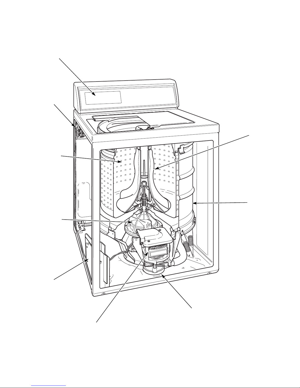
Introduction
TLW422S
Electronic Control
Agitator
Outer
Tub
Mixing
Valve
Washtub
Transmission
Motor
Pump
Output
Board
How Your Washer Works
6 203562
© Copyright, Alliance Laundry Systems LLC – DO NOT COPY or TRANSMIT
Page 9

Introduction
The cycle begins with a wash fill. The water
temperature is determined by the temperature selected
on the control. While water fills the washtub, a column
of air is trapped in a pressure bulb and hose. The air
pressure continues to increase as the washtub fills with
water until it is great enough to trip the pressure sensor
at the selected water level (load size). The pressure
sensor trip then causes the wash fill to stop and wash
agitation to begin. However, the lid must be closed for
any washer operation to occur.
The washer uses a reversing type motor, a special drive
belt and an idler assembly. The idler assembly applies
tension to the outside of the drive belt.
During agitation, the motor runs in the
counterclockwise direction. The spring tension on the
idler pulley applies the tension required to reduce the
slack on the drive belt and maintain maximum belt to
motor pulley contact. This eliminates belt slippage and
ensures an efficient wash action, even with extra large
loads.
The belt drives the transmission drive pulley in the
counterclockwise direction. The pulley drives the helix
which is splined to the input shaft of the transmission.
This causes the input shaft to turn inside of a roller
clutch which is pressed into the transmission cover.
This roller clutch acts as a bearing in the
counterclockwise direction allowing the transmission
gears to operate. The transmission’s rack and pinion
gear design produces a 210 degree agitation stroke at
the output shaft of the transmission which drives the
agitator. The brake assembly remains locked during the
agitation mode since no pressure is applied to it by the
transmission drive pulley.
As water is removed by the pump and the momentum
of the washtub increases, the idler spring tension
gradually overcomes the belt tension removing the belt
slack. This eventually increases the belt to pulley
contact until maximum spin speed is achieved.
The drive pulley turns clockwise riding up the ramps of
the helix, exerting pressure on the brake and forcing it
to release from brake pads. The helix drives the input
shaft of the transmission, and when the input shaft turns
in the clockwise direction the roller clutch locks onto
the shaft causing the entire transmission assembly to
turn. None of the gears in the transmission are
operating at this time. The hub of the washtub is splined
to the transmission tube and rotates with the
transmission assembly. The centrifugal acceleration
created by the spinning washtub causes water to be
extracted from the clothes.
Water is introduced during the first spin to “SPRAY”
the garments and remove suds from them. The initial
spin is followed by a rinse step to rinse away any
detergent residue.
During the rinse step in the Normal Eco cycle there is a
spray rinse. Water is sprayed into the washtub while it
is spinning. In all other cycles, the washer fills and then
agitates like the wash portion of the cycle.
Following the rinse step a final spin extracts the rinse
water from the clothes preparing them for the dryer.
Refer to Cycle Sequence Charts section for a detailed
breakdown of each cycle.
After the wash agitation is completed and a short pause
occurs, the control advances into the first spin. During
spin, the motor reverses turning in the clockwise
direction to spin the water out of the washtub. The
combination of water, washtub and load weight cause
the drive belt tension on the idler side of the belt to
overtake the idler spring pressure allowing the belt to
become slack on the opposite side. This reduces the
belt to pulley contact and allows slipping between the
belt and pulley.
203562 7
© Copyright, Alliance Laundry Systems LLC – DO NOT COPY or TRANSMIT
Page 10
Introduction
W429SE1B
Customer Service
If literature or replacement parts are required, contact
the source from whom the machine was purchased or
contact Alliance Laundry Systems at (920) 748-3950
for the name and address of the nearest authorized parts
distributor.
For technical assistance, call (920) 748-3121.
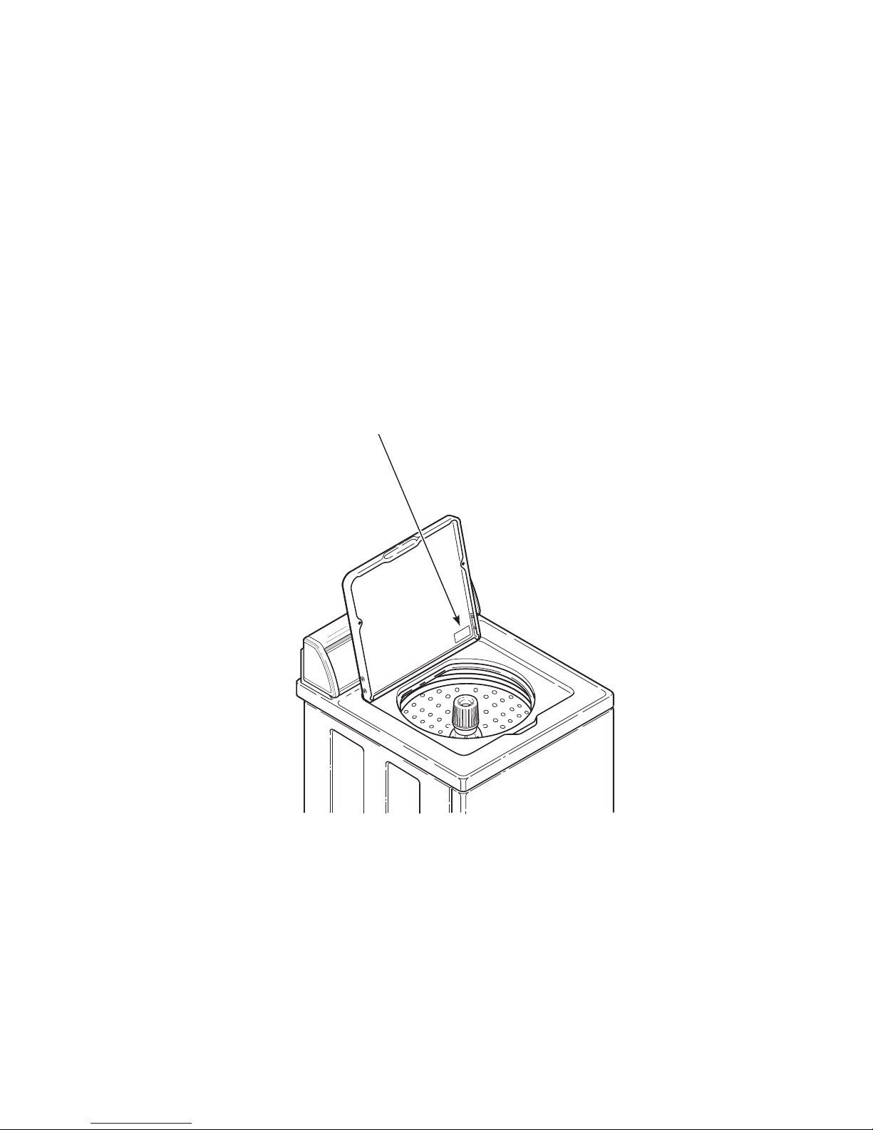
Nameplate Location
When calling or writing about your product, be sure to
mention model and serial numbers. Model and serial
numbers are located on nameplate(s) as shown.
8 203562
© Copyright, Alliance Laundry Systems LLC – DO NOT COPY or TRANSMIT
Page 11
Section 3
To reduce the risk of electric shock, fire, explosion, serious injury or death:
• Disconnect electric power to the washer before servicing.
• Never start the washer with any guards/panels removed.
• Whenever ground wires are removed during servicing, these ground wires must be
reconnected to ensure that the washer is properly grounded.
W003
WARNING
Troubleshooting
Re
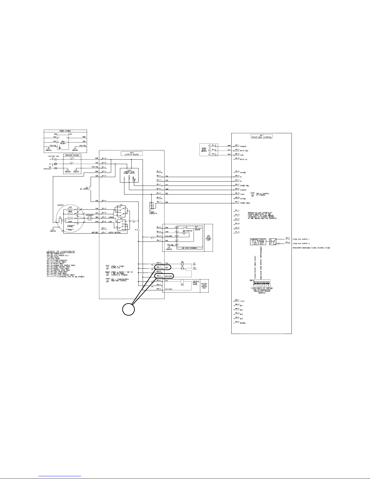
IMPORTANT: Refer to Wiring Diagram for aid in
testing washer components.
1. Production Test Summary
To enter Production Test Mode, disconnect machine
from electrical power and reconnect. Within five
minutes press keypads 2 and 7 (Refer to Figure 1) at the
same time.
Press the Start/Pause keypad to advance through the
steps.
Test Name Display LEDs Motor
Control Type “tL” All Off None Off Off Off
Control Firmware Major “XX”* All Off None Off Off Off
Output Board “ob” All Off None Off Off Off
Control Level “XX”* All Off None Off Off Off
CCB Region Display
Cycle Confirm
Control Dip Switches “XX”* All Off None Off Off Off
Keypad Test “PX” or “XX”* All Off None Off Off Off
Display Test “8.8” All On None Off On Off
High Speed Spin Test “01” Spin On High Speed Off Off Off
Hot Water Test “02” All Off None Hot Off Off
Cold Water Test “03” All Off None Cold Off Off
Warm Wat e r /
Pressure Sensor Test**
High Speed Agitate “05” Rinse On High Agitate Off Off Off
Low Speed Agitate “06” Rinse On Low Agitate Off Off Off
Low Speed Spin “07” Spin On Low Spin Off Off Off
High Speed Spin “08” Spin On High Spin Off Off Off
Warm Water Test “09” All Off None Hot, Cold Off Off
High Speed Spin/
Tub Empty Test
*“XX” displays number relating to test.
**This step will only advance automatically once specified water levels are reached.
“XX”* All Off None Off Off Off
“04” All Off None Hot, Cold Off Off
“10” Spin On High Spin Off Off Off
Table 1 (Continued)
Water
Va lv es
203562 9
© Copyright, Alliance Laundry Systems LLC – DO NOT COPY or TRANSMIT
Audio
Ton e
Auxilliary
Output
Page 12
Troubleshooting
Table 1 (Continued)
Test Name Display LEDs Motor
Auxilliary 1 “11” All Off None Off Off Aux 1
Auxilliary 2 “12” All Off None Off Off Aux 2
Auxilliary 3 “13” All Off None Off Off Aux 3
Auxilliary 4 “14” All Off None Off Off Aux 4
Power Down “Pd” All Off None Off Off Off
*“XX” displays number relating to test.
**This step will only advance automatically once specified water levels are reached.
Tab le 1
Water
Va lv es
Audio
Ton e
2. Keypad Combinations
Refer to Figure 1.
Function Keys Entry state
Enter/Exit Software Version Display Mode 7+8 Start Mode
Enter Output Board Version Display 3+14 Start Mode
Rapid Advance 7+13 Run Mode
Enter/Exit Audit Display Mode 3+9 Start Mode
Auxilliary
Output
Enter Motor Thermal Protect Counter 7+9 Start Mode
Enter Production Test Mode 2+7 Start Mode under 5 min
Enter/Exit Production Test Counter 2+9 Start Mode
Toggle Keypad Acknowledgement 13+14 Start Mode
Turn On/Off Rainbow Pizzazz display 9+10 Start Mode
Enter/Exit Show Mode 3+8 Start Mode
Pressure Sensor Display 4+14
Tab le 2
Any Mode Except
Errors
10 203562
© Copyright, Alliance Laundry Systems LLC – DO NOT COPY or TRANSMIT
Page 13
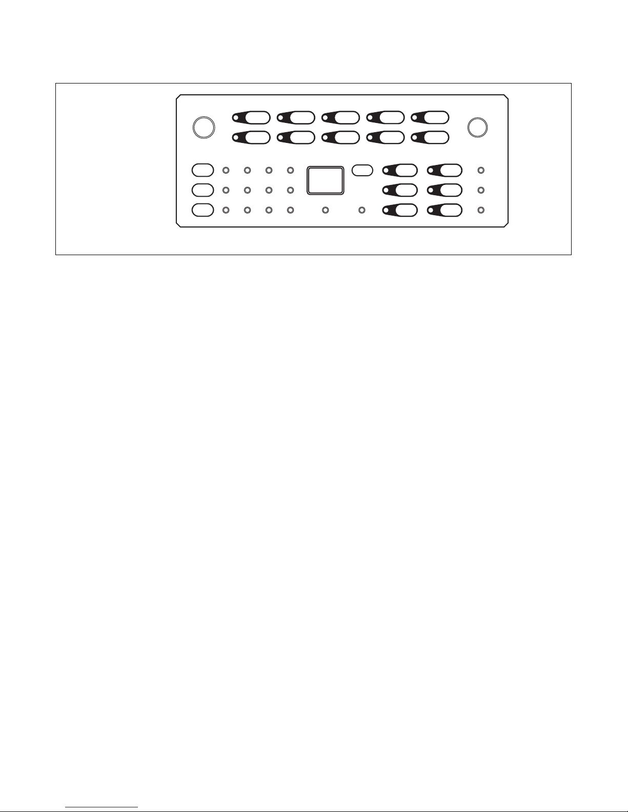
3. Rapid Advance
TLW432S
5 7 9 13 18
6 8 10 14 19
11 15 20
16 21
17 22
2
3
4
1
23
For Rapid Advance press keypads 7 and 13 at the same
time to advance to the next step of the cycle. Each time
these keypads are pressed the cycle will advance to the
next step. Then press them both again to advance
through the cycle. Refer to Cycle Sequence Charts
section for each cycle step. Fill/Agitate cycle steps
count as one Rapid Advance step.
Troubleshooting
TLW432S
Figure 1
5. Low Water Level on High Fill
Setting
a. If there is an instance of a low water level on the
highest fill setting, check that the high setting
water level is between 12 and 13.5 inches.
b. If the water level is within .5 inch of this level
without clothes, it is performing as designed.
4. Control Version Display
a. To display the software version, press keypads
7 and 8 at the same time.
b. To display the output board version, press
keypads 3 and 14 at the same time.
203562 11
© Copyright, Alliance Laundry Systems LLC – DO NOT COPY or TRANSMIT
Page 14
Troubleshooting
TLW457S
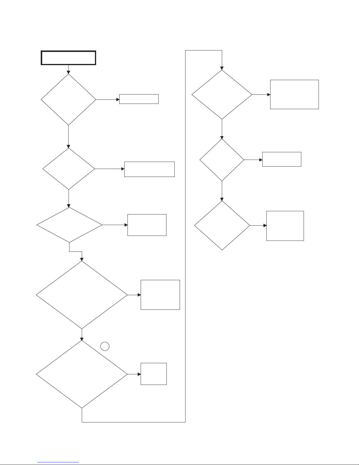
6. No Hot Water - “Er”, “FL”
There is no hot water.
Is the water
supply faucet
closed?
No
Is the water
supply cold?
No
Is the hot water
fill hose kinked?
No
Yes
Yes
Yes
Open faucet.
Check water heater.
Straighten or
replace hose.
Is there
voltage at the
Hot Solenoid?
Yes
Is
Hot Solenoid
inoperative?
No
Is
pressure hose
clogged or
damaged?
Yes
No
Replace valve.
Remove and
Yes
clean or
replace hose.
Check wiring
from output board
to water valve.
Is the mixing valve
screen or screen in
outer end of fill hose
nearest water supply
faucet clogged?
No
1
Is
there voltage
output from output
board to the Hot Solenoid
at “H4-8” and
“H4-1”?
Yes
12 203562
© Copyright, Alliance Laundry Systems LLC – DO NOT COPY or TRANSMIT
Disconnect hot
Yes
fill hose and
clean or
replace screen.
Replace
No
output
board.
TLW457S
Page 15

No Hot Water - “Er”, “FL”
TLW456S
1
Troubleshooting
203562 13
© Copyright, Alliance Laundry Systems LLC – DO NOT COPY or TRANSMIT
Page 16

Troubleshooting
There is no cold
water.
Is the water
supply faucet
closed?
Open faucet.
Yes
Is the cold
water fill hose
kinked?
Straighten or
replace hose.
Yes
Is the mixing valve
screen or screen in
outer end of fill hose
nearest water supply
faucet clogged?
No
Disconnect
cold fill hose
and clean or
replace screen.
Yes
Is
there voltage
at the output board to
the Cold Solenoid
at “H4-7” and
“H4-1”
?
No
Replace
output
board.
No
No
Replace valve.
Is Cold
Solenoid
inoperative?
Yes
Yes
Yes
No
TLW458S
No
Yes
Is
pressure
hose clogged
or damaged?
Remove and
clean or
replace hose.
Is
there voltage
to the Cold
Solenoid?
Check wiring from
output board to
water solenoid.
1
TLW458S
7. No Cold Water - “Er”, “FL”
14 203562
© Copyright, Alliance Laundry Systems LLC – DO NOT COPY or TRANSMIT
Page 17
No Cold Water - “Er”, “FL”
TLW456S
1
Troubleshooting
203562 15
© Copyright, Alliance Laundry Systems LLC – DO NOT COPY or TRANSMIT
Page 18
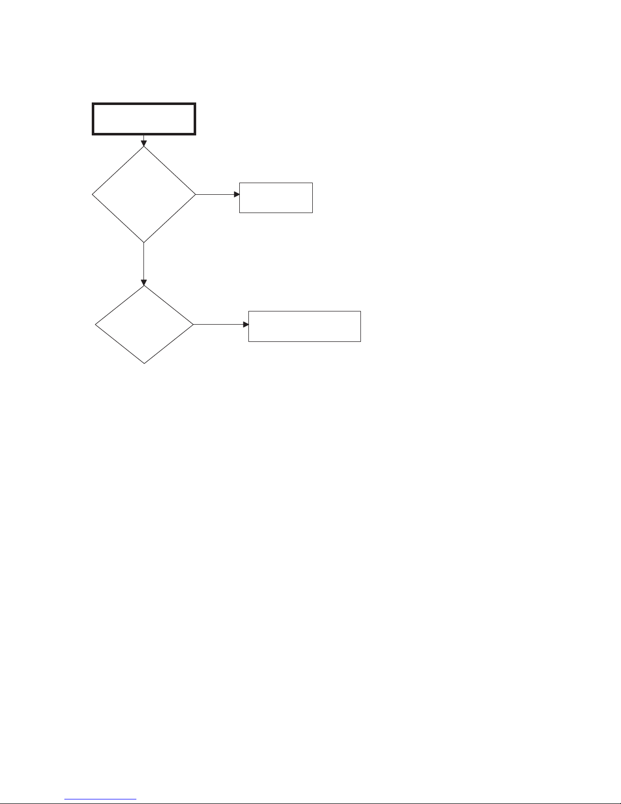
Troubleshooting
There is no warm
water.
Is there no
hot water?
Refer to
Paragraph 1.
Yes
Is there no
cold water?
No
Refer to Paragraph 2.
Yes
TLW328S
8. No Warm Water - “Er”, “FL”
16 203562
© Copyright, Alliance Laundry Systems LLC – DO NOT COPY or TRANSMIT
Page 19

9. Slow Hot Fill or Warm Fill is Too Cold
Hot fill is slow or warm fill
is too cold.
Are fill hose
filter screens
plugged with
debris?
Clean or replace
screens.
Is water
pressure too
low?
Check water pressure.
Recommended water
pressure is 20 to 120 psi.
Yes
TLW378S
Are mixing valve
screens plugged
with debris?
Clean or replace
screens.
Yes
No
No
Yes
Unit is filling properly. Recent new mandates from the
Department of Energy (DOE) call for certain efficiencies to be
met by all washer manufacturers which require the use of a
different fill valve to meet these requirements. No
modification can be made to the washer to fill faster on these
settings.
No
TLW378S
Troubleshooting
203562 17
© Copyright, Alliance Laundry Systems LLC – DO NOT COPY or TRANSMIT
Page 20

Troubleshooting
Note: To test the pressure sensor
1. Ensure sensor is connected to the front end control and there is no damage to the harness.
2. Press the 4 and 14 key pads (refer to Figure 1) at the same time while water is filling. If no change is viewed
on the display, first check pressure hose for damage. If hose is ok, replace pressure sensor.
Water fill does not
stop at proper level.
Yes
Is mixing
valve
inoperative?
Test valve and
replace if
inoperative.
Yes
Was
there a siphoning
action started in washer
causing water to be
siphoned from washer
during cycle due to end
of drain hose being
lower than cabinet top of
washer?
Install 562P3
Siphon
Break Kit.
Yes
Is there
water in
pressure
hose?
Blow air through
hose to remove
water or replace
hose.
Yes
Is there
broken,
loose,
shorted or
incorrect
wiring?
Refer to
appropriate
wiring diagram.
No
Yes
Is
there an
air leak in
pressure
hose?
Replace
hose.
Yes
No
Does drain
hose fit tight
in standpipe
or drain?
Provide an air
gap around drain
hose and drain
receptacle.
Install No. 36878
Standpipe Adapter
(optional on some
models).
No
No
No
Yes
No
No
Is there
“Er”, a PS
Pressure Sensor
error?
Is there
an “Er”, “OF”
overflow
error?
Test
pressure
sensor.
TLW425S
10. Water Fill Does Not Stop At Proper Level, Fill Error “Er”, “FL”,
Overflow Error “Er”, “OF”
18 203562
© Copyright, Alliance Laundry Systems LLC – DO NOT COPY or TRANSMIT
Page 21

11. “Er”, “PS” on the display, Pressure sensor error
Is
the pressure
sensor connected
to the front
end control
at “H-5”?
Yes
Yes
No
Yes
No
Yes
No
Connect the sensor to
the front end control
Replace pressure sensor
Clear blockage
Replace pressure sensor hose.
Is the pressure
sensor harness
damaged?
Is the
pressure bulb,
or the sensor tube
plugged?
Is the
pressure sensor
hose cracked?
If the Er PS error is still displayed,
then replace the front end control.
NOTE: The pressure sensor can be tested by pressing both the
4 and 14 keypads (refer to Figure 1) at the same time while the machine is filling.
The sensor can also be tested by performing the production test.
TLW459S
1
Troubleshooting
203562 19
© Copyright, Alliance Laundry Systems LLC – DO NOT COPY or TRANSMIT
Page 22

Troubleshooting
TLW456S
1
“Er”, “PS” on the display, Pressure sensor error
20 203562
© Copyright, Alliance Laundry Systems LLC – DO NOT COPY or TRANSMIT
Page 23

12. Washer Fills, Motor Hums
TLW426S
Washer fills, motor hums
in wash portion of cycle.
Advance control
to spin. Close
lid to run
the spin step of the cycle.
Does machine
start to spin?
Does pulley
rotate
clockwise?
Yes
Does
pulley rotate in
counter-clockwise
direction
(spin) only?
Replace transmission.
No
Unplug
machine.
Remove front
panel. Rotate main
drive pulley in both
directions. Does
pulley freely
rotate in both
directions?
Replace
control
only.
Yes
Does motor hum
in wash and spin
portions of cycle?
Unplug
machine.
Remove front
panel. Rotate main
drive pulley in both
directions. Is pulley
locked in both
directions?
Something
is jammed in
pump. Clean
or replace
pump.
Yes
Check breakes
for proper operation
Replace if needed.
No
No
Yes
No
Replace
motor.
No
Motor checks OK and
pump is clear.
Yes
TLW426S
Troubleshooting
203562 21
© Copyright, Alliance Laundry Systems LLC – DO NOT COPY or TRANSMIT
Page 24

Troubleshooting
Cycle does not advance.
Is pause part
of normal
operation?
Cycle is designed to
pause during fill steps
when going from
agitate to spin and
during soak steps
(soak LED blinks).
Allow completion
of those steps. Some
cycles (delicate) have
additional pauses.
Refer to diagram for
information on time
required.
Yes
Is lid
open?
Close lid. Lid
MUST be closed
any time the
washer is set to
agitate or spin.
Yes
Washer
will not fill?
Cycle pauses
until pressure
switch is
satisfied.
TLW460S
No
Has washer
drive motor
over loaded
and motor
thermal
overload been
tripped?
Control is designed
to stop under
these conditions.
Motor thermal
proctor reset time
may vary
depending upon
the reason for
washer overload,
however, it should
reset within 15
minutes. Check to
ensure washer
was not
overloaded with
clothes.
Yes
Is circuit breaker
to washer tripped,
disconnecting
power to washer?
Reset circuit
breaker.
No
Yes
Control is designed to
pause when going
from spin into rinse
to allow the washtub
to stop spinning
before filling. Make
sure cycle has
advanced into fill
portion of rinse
cycle.
No
Yes
No
Is there broken,
loose or incorrect
wiring?
Refer to
appropriate
wiring diagram.
Yes
Washer
will not fill?
No
Yes
Is washer
siphoning
during rinse
fill?
Install siphon
break kit, Part
No. 562P3.
No
No
Yes
Is
Lid Switch
operative?
Replace switch.
No
Yes
TLW460S
13. Cycle Does Not Advance
22 203562
© Copyright, Alliance Laundry Systems LLC – DO NOT COPY or TRANSMIT
Page 25

14. Motor Does Not Run - “tP”
Motor does not run.
Is electrical
power off, fuse
blown or power
cord not
plugged in?
Check laundry
room for blown or
loose fuse(s) or
open circuit
breakers.
(Washer itself
does not have an
electrical fuse.)
Yes
Is lid open or
lid switch
inoperative?
Close lid or
test switch and
replace if
inoperative.
Yes
Is control
improperly
set?
No
Reset control or
try another
cycle.
Replace
output
board.
Yes
Are motor
starting
functions
inoperative; no
start or motor
hums only?
Refer to Test
Procedures
section to check
start switch and
start windings.
TLW461S
No
Electronic
control. Test
the output board
for voltage to
the motor.
Yes
No
Is there
broken,
loose or
incorrect
wiring?
Refer to
appropriate
wiring diagram.
Yes
Refer to
appropriate wiring
diagram for
correct wiring.
Yes
Is motor dead,
won't run?
Refer to Test
Procedures
section to
check switch
and windings.
Yes
Is there a bind in
upper or lower
motor bearing?
Remove belt and
determine if
motor shaft will
spin. Replace
motor if shaft is
locked up.
Yes
Is power
cord
miswired?
No
Yes
Wait two or three
minutes for overload
protector to reset. If
protector cycles
repeatedly, refer to
Paragraph 9.
No
Yes
No
No
No
Is there a
bind in
pump?
Replace pump.
No
No
Yes
Has
motor overload
protector cycled?
Test for continuity
at motor pins
4 and 8.
1
TLW461S
Troubleshooting
© Copyright, Alliance Laundry Systems LLC – DO NOT COPY or TRANSMIT
203562 23
Page 26

Troubleshooting
TLW456S
1
Motor Does Not Run - “tP”
24 203562
© Copyright, Alliance Laundry Systems LLC – DO NOT COPY or TRANSMIT
Page 27

15. No Agitation
No agitation.
Motor
won't run?
Refer to Test
Procedures section
to check switch
and windings.
Yes
Has drive
motor
overload
protector
cycled?
Wait two or three
minutes for
overload protector
to reset. If
protector cycles
repeatedly, refer
to Paragraph 9.
Yes
Is there a
bind in
pump?
Replace pump.
No
Yes
Close lid or test
switch and
replace if
inoperative.
Is there
broken, loose
or incorrect
wiring?
Refer to
appropriate
wiring diagram.
Yes
Is lid open
or lid switch
inoperative?
No
Yes
Is
transmission
assembly
inoperative?
Repair or
replace
transmission
assembly.
Yes
Is drive
belt
broken or
loose?
Replace belt.
No
Yes
Are pauses
part of
normal cycle?
Control is
designed to
pause (SOAK)
during
DELICATE
cycle. Allow
completion of
SOAK period.
Yes
No delicate
cycle
agitate?
Refer to Test
Procedures
section to check
low speed switch
and windings.
No
No
Yes
No
No
No
TLW462S
NOTE: Use the production test mode to help
diagnose this issue. Refer to Production Test
Summary paragraph.
Troubleshooting
203562 25
© Copyright, Alliance Laundry Systems LLC – DO NOT COPY or TRANSMIT
Page 28

Troubleshooting
Constant agitation.
Is
output control
board
inoperative?
Test control
and replace if
inoperative.
Yes
Is there
shorted or
incorrect
wiring?
No
Refer to appropriate
wiring diagram.
Yes
TLW450S
Is transmission
assembly
inoperative?
Repair or
replace
transmission
assembly.
No
Yes
TLW450S
16. Constant Agitation
26 203562
© Copyright, Alliance Laundry Systems LLC – DO NOT COPY or TRANSMIT
Page 29

Troubleshooting
17. Washer Overheats, Cycles On Motor Thermal Protector, Switch Actuator
Kicks In And Out, “tP”
Washer is locked up or binding.
Is there
excessive
belt tension?
No
Is there a bind
in upper or
lower bearing?
No
Is there a
bind in water
pump?
Yes
Yes
Yes
Replace belt
and/or idler
spring.
Replace bearing.
Replace pump.
Are brake
pads
binding?
No
Is voltage
incorrect?
Yes
Yes
Free binding
pads or
replace pads.
Contact local
utility company
or have a
qualified
electrician
check power
supply.
No
Is there a
bind in
transmission?
Yes
Repair or replace
transmission.
No
TLW338S
203562 27
© Copyright, Alliance Laundry Systems LLC – DO NOT COPY or TRANSMIT
Page 30

Troubleshooting
Slow spin or no spin.
Is
output control board
inoperative?
Test for
continuity
through control
(refer to wiring
diagram) and
replace if
inoperative.
Yes
Motor
won't run?
Refer to Test
Procedures
section to
check switch
and windings.
Yes
Is
there no
clearance
between brake
pads and
discs?
Replace pads
and brake
assembly.
TLW463S
Wait two or three
minutes for
overload protector
to reset. If
protector cycles
repeatedly, refer
to Paragraph 9.
Yes
Is there a
bind in
pump?
Replace pump.
Yes
Close lid or test
switch and
replace if
inoperative.
Yes
Is there
broken, loose
or incorrect
wiring?
Refer to
appropriate
wiring diagram.
Yes
Is lid open
or lid switch
inoperative?
Yes
Is there oil
on belt?
Replace belt.
Yes
Is drive
belt
broken or
loose?
Replace belt.
Yes
No
No
No
No
No
No
No
No
Has drive
motor overload
protector cycled?
Test for continuity
at motor pins
4 to 8.
1
18. Slow Spin Or No Spin
NOTE: Use the production test mode to help
diagnose this issue. Refer to Production Test
Summary paragraph.
28 203562
© Copyright, Alliance Laundry Systems LLC – DO NOT COPY or TRANSMIT
Page 31

Slow Spin Or No Spin
TLW456S
1
Troubleshooting
203562 29
© Copyright, Alliance Laundry Systems LLC – DO NOT COPY or TRANSMIT
Page 32

Troubleshooting
Constant spin.
Is there
shorted or
incorrect
wiring?
Refer to appropriate
wiring diagram.
Yes
TLW464S
Is there
excessive wear
on brake pads
or missing
brake pads?
Replace brake
pads and brake
assembly.
Yes
Washtub does
not stop spinning
within seven
seconds after lid
is opened.
Replace brake
pads and brake
assembly.
No
No
Yes
Is lid switch
inoperative?
Replace lid
switch.
No
Yes
TLW464S
19. Constant Spin
NOTE: Use the production test mode to help
diagnose this issue. Refer to Production Test
Summary paragraph.
30 203562
© Copyright, Alliance Laundry Systems LLC – DO NOT COPY or TRANSMIT
Page 33

20. Washer Stops In Cycle; Quits After A Couple Loads; Is Intermittent - “tP”
Washer stops in cycle, quits
after a couple loads or is
intermittent.
Is belt tacky,
not allowing
proper slip?
Check belt and
replace if
defective.
Yes
Is belt tension
too great, not
allowing
proper slip?
Make sure idler
spring is
properly
connected.
Yes
Is control
inoperative?
No
Test control
and replace if
inoperative.
Yes
Are motor
switch
functions
inoperative?
Refer to Motor
Test Procedure
section to check
switch
functions.
TLW465S
No
Wait two or three
minutes for
overload protector
to reset. If
protector cycles
repeatedly, refer
to Paragraph 8.
Yes
Has brake,
transmission
or motor
locked up and
will not turn?
Check that all
these
components
are able to
move freely.
Yes
Refer to
appropriate wiring
diagram.
Yes
Is there
broken, loose
or incorrect
wiring?
Yes
No
No
No
No
Has
motor overload
protector cycled?
Test for continuity
at motor pins
4 to 8.
1
Troubleshooting
203562 31
© Copyright, Alliance Laundry Systems LLC – DO NOT COPY or TRANSMIT
Page 34

Troubleshooting
TLW456S
1
Washer Stops In Cycle; Quits After A Couple Loads; Is Intermittent - “tP”
32 203562
© Copyright, Alliance Laundry Systems LLC – DO NOT COPY or TRANSMIT
Page 35

21. Washer Is Locked Up Or Binding
Washer is locked up or binding.
Troubleshooting
Is there
excessive
belt tension?
No
Is there a bind
in upper or
lower bearing?
No
Is there a
bind in water
pump?
Yes
Yes
Yes
Replace belt
and/or idler
spring.
Replace bearing.
Replace pump.
Are brake
pads
binding?
No
Is voltage
incorrect?
Yes
Yes
Free binding
pads or
replace pads.
Contact local
utility company
or have a
qualified
electrician
check power
supply.
No
Is there a
bind in
transmission?
No
Yes
Repair or replace
transmission.
TLW338S
203562 33
© Copyright, Alliance Laundry Systems LLC – DO NOT COPY or TRANSMIT
Page 36

Troubleshooting
Outer tub does
not empty.
Is drain hose
kinked?
Straighten hose.
Yes
Is there an
obstruction
in outer tub
outlet hose?
Remove obstruction.
Yes
TLW339S
Is water pump
inoperative?
Replace pump.
Yes
Is drain hose out
of hose retainer
clip in back of
cabinet.
Remove washer
front panel and
install drain hose
into hose retainer
clip in back of
cabinet.
No
No
No
Yes
TLW339S
22. Outer Tub Does Not Empty “Er”, “dr” Drain Error, “Er”, “Sd” Slow Drain
34 203562
© Copyright, Alliance Laundry Systems LLC – DO NOT COPY or TRANSMIT
Page 37

23. Excessive Vibration
Excessive vibration.
Is there an
unbalanced
load in tub?
Stop washer,
redistribute
load, then
restart washer.
Yes
Is there a
broken or
disconnected
centering
spring(s)?
Connect or
replace centering
spring(s).
Yes
Is washer
unleveled?
No
Adjust leveling
legs.
Yes
Is base
damaged
(washer was
dropped)?
Replace base
assembly.
TLW357S
No
Are cabinet
screws
incorrect or
loose?
Replace with
correct screws
or tighten.
Yes
Is friction
ring
broken?
Replace
friction ring.
Yes
Relocate washer or
support floor to
eliminate weak or
"spongy" condition.
Yes
Is washer
installed on
weak, "spongy",
carpeted or
built-up floor?
Yes
No
No
No
Is there
lubricant on
pivot dome
and/or base
friction ring?
Remove
lubricant or
replace
parts.
No
Yes
Is partial
liquid filled
balance ring
leaking?
Replace
balance ring.
No
Yes
No
Troubleshooting
203562 35
© Copyright, Alliance Laundry Systems LLC – DO NOT COPY or TRANSMIT
Page 38

Troubleshooting
24. Water Leaking From Outer Tub
Water leaking from
outer tub.
Is water seal
in outer tub
leaking?
No
Is there a
hole in outer
tub?
No
Is pressure
hose or
accumulator
leaking?
Yes
Yes
Yes
Replace hub
and seal kit
assembly.
Replace outer
tub.
Replace
pressure hose
and/or
accumulator.
Is there an
obstruction in
drain causing
water to come
over top of outer
tub cover?
No
Is tub-to-
pump hose
leaking at
clamp?
Yes
Yes
Remove
obstruction.
Tighten clamp.
No
Is outer tub
cover
gasket
Yes
Replace gasket.
leaking?
No
TLW341S
36 203562
© Copyright, Alliance Laundry Systems LLC – DO NOT COPY or TRANSMIT
Page 39

25. Error Codes
To reduce the risk of electric shock, fire, explosion, serious injury or death:
• Disconnect electric power to the washer before servicing.
• Never start the washer with any guards/panels removed.
• Whenever ground wires are removed during servicing, these ground wires must be
reconnected to ensure that the washer is properly grounded.
W003
WARNING
Error Code Possible Causes Corrective Action
“Er”, “dS”: Voltage
configuration error
“Er”, “dr”: Drain Error,
control sensed water in the tub
at the end of the cycle
“Er”, “FL”: Fill Error, the
desired fill level was not
reached within 30 minutes
“Er”, “oF”: Overflow error, the
control was not able to lower the
water level within 5 minutes.
Section 4
Error Codes
The control has the incorrect voltage
dipswitch setting.
There is a disconnect power fail signal
at H2 connection on output control
board.
Restriction in the tub to pump hose,
drain hose blockage in the pump
Water supply faucet closed
Kinked or twisted fill hoses
Filter screens plugged
No voltage from output board to the
water valve (refer to appropriate
schematic)
Low water pressure
Leaky water valve
Possible Blockage in the pressure hose
Possible air leak in the pressure hose
The dipswitch setting must be corrected
To clear this error the machine must be
powered down. Reset dipswitch to the correct
voltage. Correct wiring issues.
Clear restriction from hoses
Replace the pump
To clear this error the machine must be
powered down.
Open Faucet
Straighten fill hoses
Clean or replace filter screens
Check for voltage (refer to serial plate) from
the output board to the water valves, and if
voltage is present at output board, then check
for voltage (refer to serial plate) at the water
valve. If there is voltage (refer to serial plate) at
the water valve, then replace the mixing valve.
Correct water pressure to 20-120 psi
(138-827 kPa).
To clear this error the machine must be
powered down.
Check the inlet valve
Clear blockage in pressure hose
Replace Hose if leak is found
To clear this error the machine must be
powered down.
“Er”, “PS”: The control did not
detect a valid water level input
from the pressure sensor for 30
seconds
The sensor harness is not connected to
the front end control
The sensor harness is damaged, or has a
break in the wire.
The pressure tube, or hose has a
blockage
Ensure that the sensor harness is plugged into
the front end control
Replace the sensor if the harness is damaged
Clear any blockage to the pressure tube or bulb
To clear this error the machine must be
powered down.
203562 37
© Copyright, Alliance Laundry Systems LLC – DO NOT COPY or TRANSMIT
Page 40

Error Codes
Error Code Possible Causes Corrective Action
“tP”: The thermal protection on
the motor is open
“Er” and “Co”: SCI Comm
Error
“Er” and “LE”: Water Leak
Detection Error
“Er” and “Sd”: Slow Drain
Detection Error
“Er” and “nr”: Drive Not
Ready Error
“Ed” and “XX”: Output Board
Error
“Er” and “bS”: Board Shorted
Error
“PF”: Delay Start Power Fail
Error
Machine is possibly overloaded
The brakes not functioning properly
Transmission not functioning properly
Properly load the machine
Check the function of the brakes
Check the function of the transmission
To clear this error wait for “tP” to clear. The
control will then prompt user to press Start.
Error in the communication between the
front end control and the output board.
There is a break or disconnect in the
main harness to the two controls.
Water level is dropping during the leak
Check for any burnt pins in the connectors or
any disconnections in the harness.
To clear this error the machine must be
powered down.
Check mixing valve for leaks.
detection step, if enabled.
The machine is taking longer to drain
Check the tub and drain for leaks.
than a preset time, if enabled.
Output board is not ready within one
minute.
Replace the output board.
To clear this error the machine must be
powered down.
Error received from the output board. Inspecting wire harnesses to output board.
Replace output board if wiring is not damaged.
To clear this error the machine must be
powered down.
Output board enable relay is shorted. Replace the output board.
To clear this error the machine must be
powered down.
Machine experienced a long power fail
or has been unplugged during Delay
Start Mode.
No service should be needed.
Press Power/cancel to continue normal
operation.
38 203562
© Copyright, Alliance Laundry Systems LLC – DO NOT COPY or TRANSMIT
Page 41

Section 5
To reduce the risk of electric shock, fire, explosion, serious injury or death:
• Disconnect electric power to the washer before servicing.
• Never start the washer with any guards/panels removed.
• Whenever ground wires are removed during servicing, these ground wires must be
reconnected to ensure that the washer is properly grounded.
W003
WARNING
W456SE3A
Level
Washer
Base
Locknut
Leveling
Leg
Rubber
Foot
Adjustments
26. Leveling Legs
Refer to Figure 2.
a. Place rubber feet on all four leveling legs.
b. Place washer in position on a clean, dry, and
reasonably firm floor.
c. Loosen locknuts and adjust two front leveling
legs. Once adjusted, tilt washer forward on
front legs and lower back down into position to
set the rear self-leveling legs.
d. Washer must not rock. After washer is at
desired height, tighten locknuts securely
against bottom of washer base. If these locknuts
are not tight, washer will not remain stationary
during operation.
NOTE: Improper installation, installation on
carpet or flexing of a weak floor will cause
excessive vibration.
IMPORTANT: Do not slide washer across floor
once leveling legs have been extended, as legs and
base could become damaged.
27. Belt (Agitate And Spin)
No belt adjustment is required.
203562 39
© Copyright, Alliance Laundry Systems LLC – DO NOT COPY or TRANSMIT
Figure 2
Page 42

Section 6
To reduce the risk of electric shock, fire, explosion, serious injury or death:
• Disconnect electric power to the washer before servicing.
• Never start the washer with any guards/panels removed.
• Whenever ground wires are removed during servicing, these ground wires must be
reconnected to ensure that the washer is properly grounded.
W003
WARNING
WARNING
Disconnect electric power to washer before performing the following steps:
W188
Test Procedures
28. Motor Test Procedure
IMPORTANT: Disconnect base wire harness plug from motor.
Motor test procedures using an Ohm meter.
NOTE: Resistance readings slightly out of given ranges may be due to meter conditions. These readings DO
NOT necessarily indicate motor failure.
Meter Connections
1. Ground to Each Other Terminal Open Terminal shorted to ground.
2. White to Yellow Closed Open thermal overload.
Red to Brown
3.
Blue to White
4.
Violet to White (2-speed motor) 2.5 Ohms
5.
6. “R” to Red Closed Open start (auxiliary) switch.
7. “P” to Blue (2-speed motor) Closed Open start switch 4 pole winding.
NOTE: Steps 8, 9 and 10 are with motor centrifugal mechanism in the run position.
8. “R” to Red Open Start auxiliary switch.
“P” to Blue (2-speed motor) 3 Ohms
9.
10. “P” to Blue (2-speed motor) Closed Open low (6 pole) winding run switch.
Reading
Should Be
2-8 Ohms
1-2 Ohms
(Approximate)
(approximate)
If Not
Start winding open or resistance too high or too
low.
High speed winding (4 pole) open or resistance
too high or too low.
Low winding opening; High speed winding open;
or resistance too high or too low.
Refer to Blue to White and Violet to White.
40 203562
© Copyright, Alliance Laundry Systems LLC – DO NOT COPY or TRANSMIT
Page 43

Test Procedures
To reduce the risk of electric shock, fire, explosion, serious injury or death:
• Disconnect electric power to the washer before servicing.
• Never start the washer with any guards/panels removed.
• Whenever ground wires are removed during servicing, these ground wires must be
reconnected to ensure that the washer is properly grounded.
W003
WARNING
29. Mixing Valve Solenoid Test Procedure
Mixing valve test procedures using an Ohm meter.
NOTE: Resistance readings slightly out of given ranges may be due to meter conditions. These readings DO
NOT necessarily indicate mixing valve failure.
120 Volt coils 900 - 1100 Ohms
240 Volt coils 3200 - 4000 Ohms
203562 41
© Copyright, Alliance Laundry Systems LLC – DO NOT COPY or TRANSMIT
Page 44

Section 7
Cycle Sequence Charts – Models
AWNE82SN303AW01 and
AWNE92SN303AW01
30. Normal ECO Cycle
Stage Step Time Motor Water Valve Temperature
Soak
(Select Models)
Prewash Fill
Wash Fill
Rinse** Pause
Second Rinse Fill
* Available on Select Models
** Default
*** Rinse will become a full tub rinse if either Second Rinse or Third Rinse is selected
Fill
Agitate
Soak
Drain
Spin
Agitate
Pause
Drain
Spin
Low Spin and Spray
Agitate
Soak
Agitate
Soak
Agitate
Soak
Agitate
Soak
Drain
Spin
Spray
Spin
Spin
Spray
Spin
Spray
Spin
Pause
Agitate
Pause
Drain
Spin
4:00
3:00
27:00
2:00
3:00
4:00
6:00
0:10
2:00
3:00
4:00
16:00
14:00
12:00**
10:00
30:00
16:00
14:00
12:00**
10:00
30:00
16:00
14:00
12:00**
10:00
30:00
16:00
14:00
12:00**
10:00
10:00
2:00
1:00
0:46
2:45
0:10
0:05
0:46
1:00
0:46
1:00
0:10
4:00
3:00
0:10
2:00
3:00
Continued
Off
L
Off
Off
H
Off
H
Off
Off
H
Off
L
H
H
H
H
Off
H
H
H
H
Off
H
H
H
H
Off
H
H
H
H
Off
Off
L
L
L
OFF
L
L
L
L
L
OFF
Off
H
Off
Off
H
H,W,C*,TC
H,W,C*,TC
H,W,C*,TC
TC
TC
TC
TC
42 203562
© Copyright, Alliance Laundry Systems LLC – DO NOT COPY or TRANSMIT
Page 45

Cycle Sequence Charts – Models AWNE82SN303AW01 and AWNE92SN303AW01
Continued
Stage Step Time Motor Water Valve Temperature
Third Rinse
(Select Models)
Final Spin Spin 7:00 H
Default Time 2:50:00
* Available on Select Models
** Default
*** Rinse will become a full tub rinse if either Second Rinse or Third Rinse is selected
Fill
Agitate
Pause
Drain
Spin
Fill
Agitate
Pause
Drain
Spin
4:00
3:00
0:10
2:00
3:00
4:00
3:00
0:10
2:00
3:00
Off
H
Off
Off
H
Off
H
Off
Off
H
TC
TC
203562 43
© Copyright, Alliance Laundry Systems LLC – DO NOT COPY or TRANSMIT
Page 46

Cycle Sequence Charts – Models AWNE82SN303AW01 and AWNE92SN303AW01
31. Delicate Cycle
Stage Step Time Motor
Soak
(Select Models)
Prewash Fill
Wash Fill
Rinse Fill
Second Rinse Fill
Third Rinse
(Select Models)
Final Spin Spin 5:00 L
Default Time 32:00
* Available on Select Models
** Default
Fill
Agitate
Soak
Drain
Spin
Agitate
Pause
Drain
Spin
Agitate
Soak
Agitate
Soak
Agitate
Soak
Drain
Spin
Spray
Spin
Agitate
Pause
Drain
Spin
Agitate
Pause
Drain
Spin
Fill
Agitate
Pause
Drain
Spin
Fill
Agitate
Pause
Drain
Spin
4:00
3:00
27:00
2:00
3:00
4:00
6:00
0:10
2:00
3:00
4:00
0:40
0:30
0:20**
0:10
3:20
2:20
1:20**
0:50
0:40
0:30
0:20**
0:10
3:20
2:20
1:20**
0:50
0:40
0:30
0:20**
0:10
3:20
2:20
1:20**
0:50
2:00
1:00
0:50
2:45
4:00
3:00
0:10
2:00
3:00
4:00
3:00
0:10
2:00
3:00
4:00
3:00
0:10
2:00
3:00
4:00
3:00
0:10
2:00
3:00
Off
L
Off
Off
L
Off
L
Off
Off
L
Off
L
L
L
L
Off
L
L
L
L
L
L
L
Off
L
L
L
L
L
L
L
Off
L
L
L
Off
L
L
L
Off
L
Off
Off
L
Off
L
Off
Off
L
Off
L
Off
Off
L
Off
L
Off
Off
L
Water Valve
Temperature
H,W,C*,TC
H,W,C*,TC
H,W,C*,TC
TC
TC
TC
TC
TC
44 203562
© Copyright, Alliance Laundry Systems LLC – DO NOT COPY or TRANSMIT
Page 47

32. All Other Cycles
Heavy Duty
Whites
(Select Models) Perm Press
Quick Wash
(Select Models)
Bulky
(Select Models) Water Valves
Stage Step Time Time Motor Time Motor Time Time Motor Time Temp
Soak
(Select Models)
Fill
Agitate
Soak
Drain
Spin
4:00
3:00
27:00
2:00
3:00
OffLOff
Off
H
OffLOff
Off
H
OffLOff
Off
L
OffLOff
Off
H
OffLOff
Off
H
H,W,C*,TC
Prewash
Fill
Agitate
Pause
Drain
Spin
4:00
6:00
0:10
2:00
3:00
OffHOff
Off
H
OffHOff
Off
H
OffHOff
Off
L
OffHOff
Off
H
OffLOff
Off
H
H,W,C*,TC
Was h
Fill
Agitate
Pause
Drain
Spin
Spray
Spin
4:00
0:10
2:00
1:00
0:50
2:45
11:00
9:00
7:00**
5:00
Off
H
HHH
Off
Off
LLL
13:00
11:00
9:00**
7:00
Off
HHH
H
Off
Off
LLL
8:00
6:00
5:00**
4:00
Off
HHH
H
Off
Off
LLL
6:00
5:00
4:00**
3:00
Off
HHH
H
Off
Off
LLL
13:00
11:00
9:00**
7:00
Off
LLL
L
Off
Off
LLL
H,W,C*,TC
Rinse
Fill
Agitate
Pause
Drain
Spin
4:00
3:00
0:10
2:00
3:00
OffHOff
Off
H
OffHOff
Off
H
OffHOff
Off
L
OffHOff
Off
H
OffLOff
Off
H
TC
Second Rinse
Fill
Agitate
Pause
Drain
Spin
4:00
3:00
0:10
2:00
3:00
OffHOff
Off
H
OffHOff
Off
H
OffHOff
Off
L
OffHOff
Off
H
OffLOff
Off
H
TC
Third Rinse
(Select Models)
Fill
Agitate
Pause
Drain
Spin
Fill
Agitate
Pause
Drain
Spin
4:00
3:00
0:10
2:00
3:00
4:00
3:00
0:10
2:00
3:00
OffHOff
OffHOffHOff
Off
H
OffHOff
OffHOffHOff
Off
H
OffHOff
OffLOffHOff
Off
L
OffHOff
OffHOffHOff
Off
H
OffLOff
OffHOffLOff
Off
H
TC
TC
Final Spin 5:00 H H L H H
*Default 35 37 33 32 37
* Available on Select Models
** Default
Cycle Sequence Charts – Models AWNE82SN303AW01 and AWNE92SN303AW01
203562 45
© Copyright, Alliance Laundry Systems LLC – DO NOT COPY or TRANSMIT
Page 48

Section 8
Cycle Sequence Charts – Models
LWNE52SP543RW01, LWNE52WP543RW01
and YWNE52SP543RW01
33. Normal ECO Cycle
Stage Step Time Motor
Prewash Fill
Wash Fill
Rinse** Fill
Second Rinse Fill
Final Spin Spin 7:00 H
Default Time 1:49:00
* Default
** Rinse will become a full tub rinse if Second Rinse is selected
Agitate
Pause
Spin
Agitate
Soak
Agitate
Soak
Agitate
Pause
Spin
Spray
Spin
Agitate
Pause
Spin
Agitate
Pause
Spin
4:00
6:00
0:10
3:00
4:00
13:00
12:00
11:00*
3:00
25:00
13:00
12:00
11:00*
3:00
25:00
13:00
12:00
11:00*
3:00
0:10
1:00
0:50
2:45
4:00
3:00
0:10
3:00
4:00
3:00
0:10
3:00
Off
H
Off
H
Off
H
H
H
H
Off
H
H
H
H
Off
H
H
H
H
Off
L
L
L
Off
H
Off
H
Off
H
Off
H
Water Valve
Temperature
H,W,TC
H,W,TC
TC
TC
TC
46 203562
© Copyright, Alliance Laundry Systems LLC – DO NOT COPY or TRANSMIT
Page 49

Cycle Sequence Charts – Models LWNE52SP543RW01, LWNE52WP543RW01 and YWNE52SP543RW01
34. Delicate Cycle
Stage Step Time Motor
Prewash Fill
Agitate
Pause
Spin
Wash Fill
Agitate
Soak
Agitate
Soak
Agitate
Soak
Spin
Spray
Spin
Rinse Fill
Agitate
Pause
Spin
Second Rinse Fill
Agitate
Pause
Spin
Final Spin Spin 5:00 L
Default Time 28:45
*Default
4:00
6:00
0:10
3:00
4:00
0:40
0:30
0:20*
0:10
3:20
2:20
1:20*
0:50
0:40
0:30
0:20*
0:10
3:20
2:20
1:20*
0:50
0:40
0:30
0:20*
0:10
3:20
2:20
1:20*
0:50
1:00
0:50
2:45
4:00
3:00
0:10
3:00
4:00
3:00
0:10
3:00
Off
L
Off
L
Off
L
L
L
L
Off
L
L
L
L
L
L
L
Off
L
L
L
L
L
L
L
Off
L
L
L
L
L
L
Off
L
Off
L
Off
L
Off
L
Water Valve
Temperature
H,W,TC
H,W,TC
TC
TC
TC
203562 47
© Copyright, Alliance Laundry Systems LLC – DO NOT COPY or TRANSMIT
Page 50

Cycle Sequence Charts – Models LWNE52SP543RW01, LWNE52WP543RW01 and YWNE52SP543RW01
35. All Other Cycles
Heavy Duty Perm Press Water Valves
Stage Step Time Time Motor Time Temp
Fill
Agitate
Pause
Prewash
Was h
Rinse
Second Rinse
Final Spin 5:00 H L
*Default 31 29
* Default
Spin
Fill
Agitate
Pause
Spin
Spray
Spin
Fill
Agitate
Pause
Spin
Fill
Agitate
Pause
Spin
4:00
6:00
0:10
3:00
4:00
0:10
1:00
0:50
2:45
4:00
3:00
0:10
3:00
4:00
3:00
0:10
3:00
11:00
9:00
7:00*
5:00
Off
H
Off
H
Off
H
H
H
H
Off
L
L
L
Off
H
Off
H
Off
H
Off
H
8:00
6:00
5:00*
4:00
Off
H
Off
Off
H
H
H
H
Off
Off
H
Off
Off
H
Off
H,W,TC
L
H,W,TC
L
L
L
TC
L
TC
L
48 203562
© Copyright, Alliance Laundry Systems LLC – DO NOT COPY or TRANSMIT
Page 51

Section 9
Cycle Sequence Charts – Model
LWNA52SP113TW01
36. Normal ECO Cycle
Stage Step Time Motor Water Valve Temperature
Prewash Fill
Agitate
Pause
Spin
Wash Fill
Agitate
Pause
Spin
Spray
Spin
Pause
Second Rinse Fill
Agitate
Pause
Spin
Final Spin Spin 9:00 H
Default Time 25:00
* Default
4:00
4:00
0:10
3:00
4:00
11:00
9:00
7:00*
5:00
0:10
1:00
0:44
2:45
0:10
4:00
3:00
0:10
3:00
Off
H
Off
H
Off
H
H
H
H
Off
L
L
L
Off
Off
L
Off
H
H,W,TC
H,W,TC
TC
TC
203562 49
© Copyright, Alliance Laundry Systems LLC – DO NOT COPY or TRANSMIT
Page 52

Cycle Sequence Charts – Model LWNA52SP113TW01
37. Delicate Cycle
Stage Step Time Motor Water Valve Temperature
Prewash Fill
Agitate
Pause
Spin
Wash Fill
Agitate
Soak
Agitate
Soak
Agitate
Soak
Spin
Spray
Spin
Rinse Fill
Agitate
Pause
Spin
Second Rinse Fill
Agitate
Pause
Spin
Final Spin Spin 5:00 L
Default Time 29:00
*Default
4:00
6:00
0:10
3:00
4:00
0:40
0:30
0:20*
0:10
3:20
2:20
1:20*
0:50
0:40
0:30
0:20*
0:10
3:20
2:20
1:20*
0:50
0:40
0:30
0:20*
0:10
3:20
2:20
1:20*
0:50
1:00
0:50
2:45
4:00
3:00
0:10
3:00
4:00
3:00
0:10
3:00
Off
L
Off
L
Off
L
L
L
L
Off
L
L
L
L
L
L
L
Off
L
L
L
L
L
L
L
Off
L
L
L
L
L
L
Off
L
Off
L
Off
L
Off
L
H,W,TC
H,W,TC
TC
TC
TC
50 203562
© Copyright, Alliance Laundry Systems LLC – DO NOT COPY or TRANSMIT
Page 53

Cycle Sequence Charts – Model LWNA52SP113TW01
38. All Other Cycles
Heavy Duty Perm Press Water Valves
Stage Step Time Time Motor Time Motor Temp
Fill
Agitate
Pause
Prewash
Was h
Rinse
Second Rinse
Final Spin 5:00 H L
*Default 31 29
* Default
Spin
Fill
Agitate
Pause
Spin
Spray
Spin
Fill
Agitate
Pause
Spin
Fill
Agitate
Pause
Spin
4:00
6:00
0:10
3:00
4:00
0:10
1:00
0:50
2:45
4:00
3:00
0:10
3:00
4:00
3:00
0:10
3:00
11:00
9:00
7:00*
5:00
Off
L
Off
H
Off
L
L
L
L
Off
L
L
L
Off
L
Off
H
Off
L
Off
H
8:00
6:00
5:00*
4:00
Off
L
Off
L
Off
L
L
L
L
Off
L
L
L
Off
L
Off
L
Off
L
Off
L
H,W,TC
H,W,TC
TC
TC
203562 51
© Copyright, Alliance Laundry Systems LLC – DO NOT COPY or TRANSMIT
Page 54

Section 10
Cycle Sequence Charts – All Other Models
39. Normal ECO Cycle
Stage Step Time Motor Water Valve Temperature
Soak
(Select Models)
Prewash Fill
Wash Fill
Rinse*** Pause
Second Rinse Fill
Third Rinse
(Select Models)
Final Spin Spin 9:00 H
Default Time 29:00
* Available on Select Models
** Default
*** Rinse will become a full tub rinse if either Second Rinse is selected
Fill
Agitate
Soak
Spin
Agitate
Pause
Spin
Agitate
Pause
Spin
Spray
Spin
Spin
Spray
Spin
Spray
Spin
Pause
Agitate
Pause
Spin
Fill
Agitate
Pause
Spin
Fill
Agitate
Pause
Spin
4:00
3:00
27:00
3:00
4:00
6:00
0:10
3:00
4:00
11:00
9:00
7:00**
5:00
0:10
1:00
0:44
2:45
0:10
0:05
0:30
1:00
0:30
1:00
0:10
4:00
3:00
0:10
3:00
4:00
3:00
0:10
3:00
4:00
3:00
0:10
3:00
Off
L
Off
H
Off
H
Off
H
Off
H
H
H
H
Off
L
L
L
OFF
L
L
L
L
L
OFF
Off
H
Off
H
Off
H
Off
H
Off
H
Off
H
H,W,C*,TC
H,W,C*,TC
H,W,C*,TC
TC
TC
TC
TC
TC
TC
52 203562
© Copyright, Alliance Laundry Systems LLC – DO NOT COPY or TRANSMIT
Page 55

40. Delicate Cycle
Stage Step Time Motor Water Valve Temperature
Soak
(Select Models)
Prewash Fill
Wash Fill
Rinse Fill
Second Rinse Fill
Third Rinse
(Select Models)
Final Spin Spin 5:00 L
Default Time 29:00
*Default
Fill
Agitate
Soak
Spin
Agitate
Pause
Spin
Agitate
Soak
Agitate
Soak
Agitate
Soak
Spin
Spray
Spin
Agitate
Pause
Spin
Agitate
Pause
Spin
Fill
Agitate
Pause
Spin
Fill
Agitate
Pause
Spin
4:00
3:00
27:00
3:00
4:00
6:00
0:10
3:00
4:00
0:40
0:30
0:20*
0:10
3:20
2:20
1:20*
0:50
0:40
0:30
0:20*
0:10
3:20
2:20
1:20*
0:50
0:40
0:30
0:20*
0:10
3:20
2:20
1:20*
0:50
1:00
0:50
2:45
4:00
3:00
0:10
3:00
4:00
3:00
0:10
3:00
4:00
3:00
0:10
3:00
4:00
3:00
0:10
3:00
Cycle Sequence Charts – All Other Models
Off
L
Off
H
Off
L
Off
L
Off
L
L
L
L
Off
L
L
L
L
L
L
L
Off
L
L
L
L
L
L
L
Off
L
L
L
L
L
L
Off
L
Off
L
Off
L
Off
L
Off
L
Off
L
Off
L
Off
L
H,W,C,TC
H,W,C,TC
H,W,C,TC
TC
TC
TC
TC
TC
203562 53
© Copyright, Alliance Laundry Systems LLC – DO NOT COPY or TRANSMIT
Page 56

Cycle Sequence Charts – All Other Models
Heavy Duty
Whites
(Select Models) Perm Press
Quick Wash
(Select Models)
Bulky
(Select Models) Water Valves
Stage Step Time Time Motor Time Motor Time Motor Time Motor Time Motor Temp
Soak
(Select Models)
Fill
Agitate
Soak
Spin
4:00
3:00
27:00
3:00
OffLOff
H
OffLOff
H
OffLOff
L
OffLOff
H
OffLOff
H
H,W,C,TC
Prewash
Fill
Agitate
Pause
Spin
4:00
6:00
0:10
3:00
OffHOff
H
OffHOff
H
OffHOff
L
OffHOff
H
OffLOff
H
H,W,C,TC
Was h
Fill
Agitate
Pause
Spin
Spray
Spin
4:00
0:10
1:00
0:50
2:45
11:00
9:00
7:00*
5:00
Off
HHH
H
Off
LLL
13:00
11:00
9:00*
7:00
Off
HHH
H
Off
LLL
8:00
6:00
5:00*
4:00
Off
HHH
H
Off
L
L
L
6:00
5:00
4:00*
3:00
Off
HHH
H
Off
LLL
13:00
11:00
9:00*
7:00
Off
LLL
L
Off
LLL
H,W,C,TC
Rinse
Fill
Agitate
Pause
Spin
4:00
3:00
0:10
3:00
OffHOff
H
OffHOff
H
OffHOff
L
OffHOff
H
OffLOff
H
TC
Second Rinse
Fill
Agitate
Pause
Spin
4:00
3:00
0:10
3:00
OffHOff
H
OffHOff
H
OffHOff
L
OffHOff
H
OffLOff
H
TC
Third Rinse
(Select Models)
Fill
Agitate
Pause
Spin
Fill
Agitate
Pause
Spin
4:00
3:00
0:10
3:00
4:00
3:00
0:10
3:00
OffHOffHOffHOff
H
OffHOffHOff
H
Off
H
OffHOffLOffHOff
L
OffHOffHOffHOff
H
OffLOffHOffLOff
H
TC
TC
Final Spin 5:00 H H L H H
*Default 31 33 29 28 33
*Default
41. All Other Cycles
54 203562
© Copyright, Alliance Laundry Systems LLC – DO NOT COPY or TRANSMIT
Page 57

Section 11
To reduce the risk of electric shock, fire, explosion, serious injury or death:
• Disconnect electric power to the washer before servicing.
• Never start the washer with any guards/panels removed.
• Whenever ground wires are removed during servicing, these ground wires must be
reconnected to ensure that the washer is properly grounded.
W003
WARNING
White
W310SE3A
Brown
Blue
Yellow
Red
R
W
BR
BU
Y
P
AUX.
RED
WHITE
RUN
START
G
Y
BU
BR
W
R
4P M
YELLOW
BROWN
BLUE
YELLOW
OVERLOAD
PROTECTOR
W211SE3A
Internal Wiring of Washer Motor Switch
203562 55
MOTOR ASSEMBLY
© Copyright, Alliance Laundry Systems LLC – DO NOT COPY or TRANSMIT
(1 Speed Motors)
Page 58

Internal Wiring of Washer Motor Switch
To reduce the risk of electric shock, fire, explosion, serious injury or death:
• Disconnect electric power to the washer before servicing.
• Never start the washer with any guards/panels removed.
• Whenever ground wires are removed during servicing, these ground wires must be
reconnected to ensure that the washer is properly grounded.
W003
WARNING
W311SE3B
Wire
Harness
Connection
Block
White
Brown
Blue
Yellow
Violet
Red
R
P
Y
BU
BR
W
RUN
START
G
Y
BR
BU
RED
VIOLET
BLUE
4P M
6P M
W224SE3A
OVERLOAD
PROTECTOR
P
BROWN
W
YELLOW
AUX.
R
WHITE
YELLOW
56 203562
© Copyright, Alliance Laundry Systems LLC – DO NOT COPY or TRANSMIT
MOTOR ASSEMBLY
(2 Speed Motors)
Page 59

Page 60

 Loading...