

Page 1
Washer-Extractor
CFD198R
CFD198R
Cygnus Professional
Refer to Page 3 for Model Numbers
Programming
Keep These Instructions for Future Reference.
(If this machine changes ownership, this manual must accompany machine.)
www.comlaundry.com
Part No. D1353ENR1
September 2012
Page 2

Page 3

NOTE: The WARNING and IMPORTANT
Failure to install, maintain, and/or operate
this machine according to the
manufacturer's instructions may result in
conditions which can produce bodily injury
and/or property damage.
W030
WARNING
instructions appearing in this manual are not meant
to cover all possible conditions and situations that
may occur. It must be understood that common
sense, caution, and carefulness are factors which
cannot be built into these washer-extractors. These
factors MUST BE supplied by the person(s)
installing, maintaining, or operating the washerextractor.
Always contact the distributor, service agent, or the
manufacturer about any problems or conditions you do
not understand.
D1353 (EN)
© Copyright, Alliance Laundry Systems LLC – DO NOT COPY or TRANSMIT
1
Page 4

Table of
Contents
Model Identification ........................................................................... 3
Preliminary Information.................................................................... 6
About the Control ................................................................................. 6
Glossary of Terms................................................................................. 6
Power Failure Recovery ....................................................................... 6
Communications ................................................................................... 6
Control Identification......................................................................... 7
Selection Keypads ................................................................................ 7
Display Identification ......................................................................... 8
Cycle Screen ......................................................................................... 8
Special Features .................................................................................. 11
Programming Control ........................................................................... 11
Viewing Control Information ............................................................... 11
Testing Machine Components .............................................................. 11
Rapid Advance Feature......................................................................... 11
Communication Mode .......................................................................... 11
Washer-Extractor Operation ............................................................ 12
Start Up................................................................................................. 12
Start Mode ............................................................................................ 12
Run Mode ............................................................................................. 12
Stop Mode............................................................................................. 12
End of Cycle Mode............................................................................... 12
The Non-Active Menu ........................................................................ 13
What is Available in the Non-Active Menu? ....................................... 13
Non-Active Menu Navigation.......................................................... 14
Non-Active Menu Options ................................................................... 16
1. Logbook Sub-Menu ..................................................................... 16
2. Info Sub-Menu ............................................................................. 17
3. Advanced Functions Sub-Menu................................................... 20
3.1 Test Menu .................................................................................. 21
3.2 Edit Menu................................................................................... 28
3.3 Edit Menu Subroutine ................................................................ 34
3.4 Data Transfer Menu ................................................................... 35
3.5 Settings Menu ............................................................................ 44
Error Messages ................................................................................... 50
Events................................................................................................... 53
Rapid Advance Feature...................................................................... 55
How to Use Rapid Advance............................................................. 55
Communication Mode........................................................................ 56
Infra-red Communications.................................................................... 56
© Copyright 2012, Alliance Laundry Systems LLC
All rights reserved. No part of the contents of this book may be reproduced or transmitted in any form or by any
means without the expressed written consent of the publisher.
2
© Copyright, Alliance Laundry Systems LLC – DO NOT COPY or TRANSMIT
D1353 (EN)
Page 5

Model Identification
Information in this manual is applicable to these
washer-extractor models:
CHF455
CHF575
CHF730
CHG065Z
CHG075Z
CHG100Z
CHG135Z
CHG150Z
CHG165Z
CHG185Z
CHG235Z
CHG305Z
CHG400Z
CHN065Z
CHN075Z
CHN100Z
CHN135Z
CHW065Z
CHW075Z
CHW100Z
CHW135Z
CHW150Z
CHW165Z
CHW185Z
CHW235Z
CHW305Z
CHW400Z
CHZ065Z
CHZ075Z
CHZ100Z
CHZ135Z
CHZ150Z
CHZ165Z
CHZ185Z
CXN165Z
CXN235Z
CXN305Z
CXU060Z
CXU065Z
CXU075Z
CXU100Z
CXU135Z
CXU165Z
CXU235Z
CXU305Z
CXW060Z
CXW065Z
CXW075Z
CXW100Z
CXW135Z
CXW165Z
CHN150Z
CHN165Z
CHN185Z
CHN235Z
CHN305Z
CHN400Z
CHU065Z
CHU075Z
CHU100Z
CHU135Z
CHU150Z
CHU165Z
CHU185Z
CHU235Z
CHU305Z
CHU400Z
CHZ235Z
CHZ305Z
CHZ400Z
CXG060Z
CXG065Z
CXG075Z
CXG100Z
CXG135Z
CXG165Z
CXG235Z
CXG305Z
CXN060Z
CXN065Z
CXN075Z
CXN100Z
CXN135Z
CXW235Z
CXW305Z
CXZ060Z
CXZ065Z
CXZ075Z
CXZ100Z
CXZ135Z
CXZ165Z
CXZ235Z
CXZ305Z
HD100_CYGNUS-PRO
HD135_CYGNUS-PRO
HD165_CYGNUS-PRO
HD235_CYGNUS-PRO
HD305_CYGNUS-PRO
HD60_CYGNUS-PRO
(Continued)
D1353 (EN)
© Copyright, Alliance Laundry Systems LLC – DO NOT COPY or TRANSMIT
3
Page 6

Model Identification
HD65_CYGNUS-PRO
IHU185Z
(Continued)
XN100Z
HD75_CYGNUS-PRO
HF455_CYGNUS-PRO_OPL
HF575_CYGNUS-PRO_OPL
HF730_CYGNUS-PRO_OPL
HF900_CYGNUS-PRO_OPL
IHF455
IHF575
IHF730
IHG065Z
IHG075Z
IHG100Z
IHG135Z
IHG150Z
IHG165Z
IHG185Z
IHG235Z
IHG305Z
IHU235Z
IHU305Z
IHU400Z
IHW065Z
IHW075Z
IHW100Z
IHW135Z
IHW150Z
IHW165Z
IHW185Z
IHW235Z
IHW305Z
IHW400Z
IHZ065Z
IHZ075Z
IHZ100Z
IHZ135Z
IXN135Z
IXN165Z
IXN235Z
IXN305Z
IXU060Z
IXU065Z
IXU075Z
IXU100Z
IXU135Z
IXU165Z
IXU235Z
IXU305Z
IXW060Z
IXW065Z
IXW075Z
IXW100Z
IXW135Z
IHG400Z
IHN065Z
IHN075Z
IHN100Z
IHN135Z
IHN150Z
IHN165Z
IHN185Z
IHN235Z
IHN305Z
IHN400Z
IHU065Z
IHU075Z
IHU100Z
IHU135Z
IHU150Z
IHU165Z
IHZ150Z
IHZ165Z
IHZ185Z
IHZ235Z
IHZ305Z
IHZ400Z
IXG060Z
IXG065Z
IXG075Z
IXG100Z
IXG135Z
IXG165Z
IXG235Z
IXG305Z
IXN060Z
IXN065Z
IXN075Z
IXW165Z
IXW235Z
IXW305Z
IXZ060Z
IXZ065Z
IXZ075Z
IXZ100Z
IXZ135Z
IXZ165Z
IXZ235Z
IXZ305Z
JHW065Z
JHW075Z
JHW100Z
JHW135Z
JHW150Z
JHW165Z
(Continued)
4
© Copyright, Alliance Laundry Systems LLC – DO NOT COPY or TRANSMIT
D1353 (EN)
Page 7

JHW185Z
JXW100Z
Model Identification
(Continued)
WD150_CYGNUS-PRO
JHW235Z
JHW305Z
JHW400Z
JXW060Z
JXW065Z
JXW075Z
JXW135Z
JXW165Z
JXW235Z
JXW305Z
WD100_CYGNUS-PRO
WD135_CYGNUS-PRO
WD165_CYGNUS-PRO
WD185_CYGNUS-PRO
WD235_CYGNUS-PRO
WD400_CYGNUS-PRO
WD65_CYGNUS-PRO
WD75_CYGNUS-PRO
D1353 (EN)
© Copyright, Alliance Laundry Systems LLC – DO NOT COPY or TRANSMIT
5
Page 8

Preliminary Information
About the Control
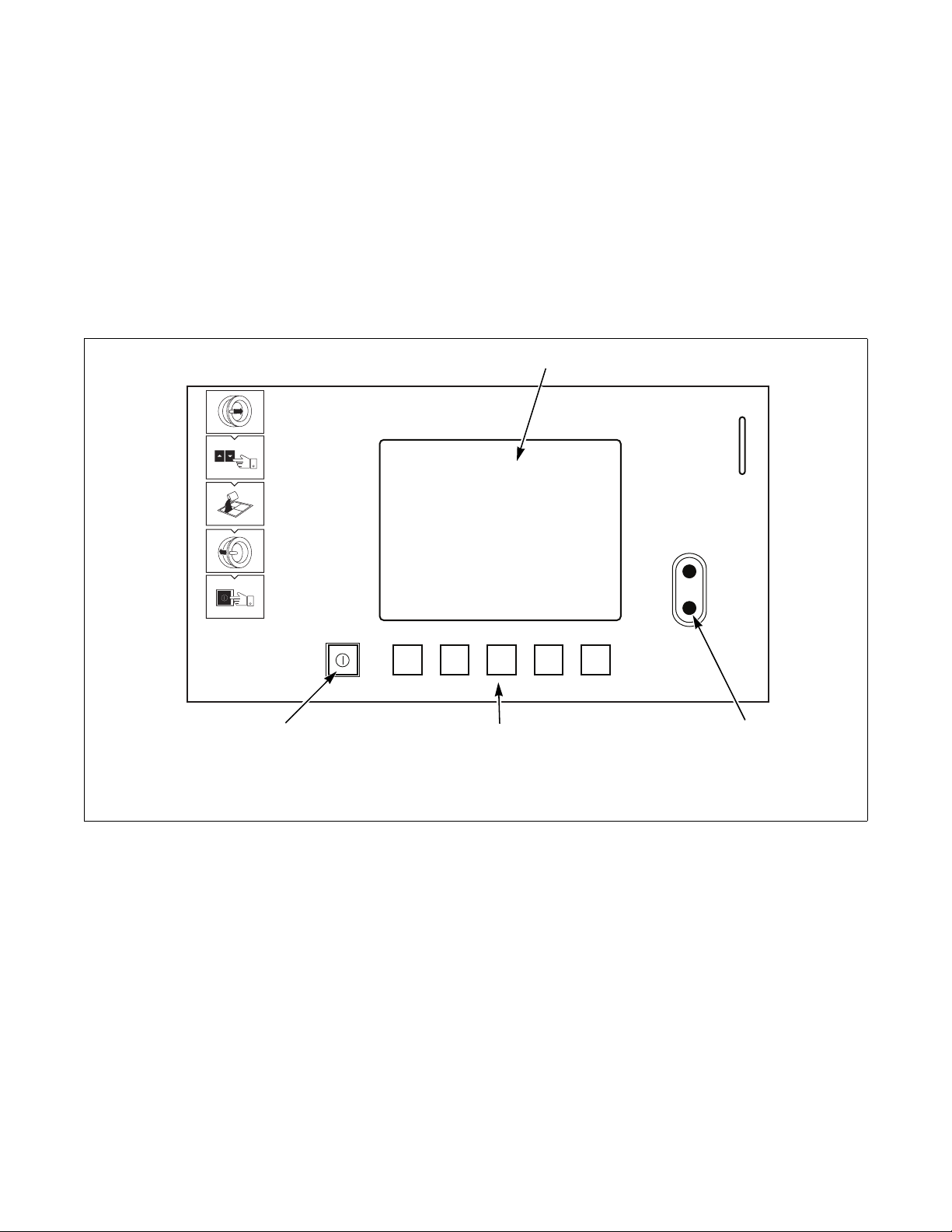
This control is an advanced, programmable computer
that lets the operator control machine features by
pressing a sequence of keypads. Refer to Figure 1.
The control allows the operator to obtain information
from the machine, run test cycles, modify the control’s
programmable features, set the service counters and
view the error code history. Refer to The Non-Active
Menu section for a list of features.
IMPORTANT: In the event of a power failure, the
control will not have to be reprogrammed. It is
designed with a memory system that will remember
how it was programmed until the electrical power
is restored.
IMPORTANT: It is extremely important that the
washer-extractor has a good ground connection and
that all mechanical and electrical connections to the
control are made before applying power to or
operating the washer-extractor.
Glossary of Terms
Communications
The control may be programmed manually or by infrared communication with an external device.
Infra-red Communications
A PC allows the owner to program and retrieve
information from the control without using the
machine’s keypad, which greatly expands the
programming options available to the owner. However,
it is not required to program and operate the washerextractor. The operation of a PC and the advanced
features available are covered separately in the
instructions included with the PC programming
software, Cygnus Assist.
The following are a few terms and abbreviations to
learn. These are referred to throughout the instructions.
Display – This term refers to the window area of the
control that displays words and values.
Power Failure Recovery
If a cycle is in progress and the power fails, the water
will be drained from the machine and the door can be
opened after approximately 3 minutes. If the door is not
opened and the power failure is shorter than 2 weeks,
the washer-extractor will resume the previously active
cycle.
If the door is opened or if the length of the power failure
is longer than 2 weeks, the control will end the cycle
and the display will revert back to Start Mode.
6
© Copyright, Alliance Laundry Systems LLC – DO NOT COPY or TRANSMIT
D1353 (EN)
Page 9
Control Identification
1
3
2
4
Selection Keypads
(Refer to Figure 1)
The Selection keypads are used in various combinations
to obtain information from the machine, run wash
cycles, run test cycles, modify the control’s
programmable features, set the service counters and
view the error code history. These instructions cover
the manual programming and data retrieval options.
1 Display 3 Selection keypads
2 Optical Download Window 4 Start/Stop keypad
Figure 1
CFD198R
CFD198R
D1353 (EN)
© Copyright, Alliance Laundry Systems LLC – DO NOT COPY or TRANSMIT
7
Page 10
Display Identification
CFD936R
Hot wash 30°-90°C
40 °C
26.0cm
27°C
1h 09
1
2
3
4
5
6
7
8
9
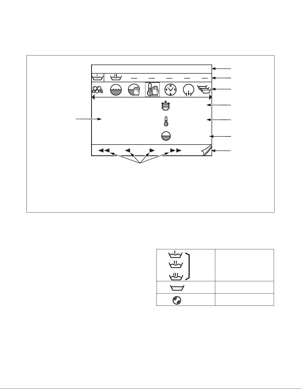
Cycle Screen
1 Title Bar 6 Water Level
2 Cycle Phase Bar 7 Next Screen
3 Step Bar 8 Navigation
4 Cycle Time Remaining 9 Info
5 Water Temperature
CFD936R
Title Bar (Refer to Figure 2, Item 1)
Displays the cycle.
Figure 2
Cycle Phase Bar (Refer to Figure 2, Item 2)
Displays how the various phases of the cycle are
progressing. The active phase is highlighted.
CFD203R
CFD202R
CFD201R
CFD204R
CFD205R
Wash C y cl e
Rinse Cycle
Spin Cycle
Ta bl e 1
8
© Copyright, Alliance Laundry Systems LLC – DO NOT COPY or TRANSMIT
D1353 (EN)
Page 11
Display Identification
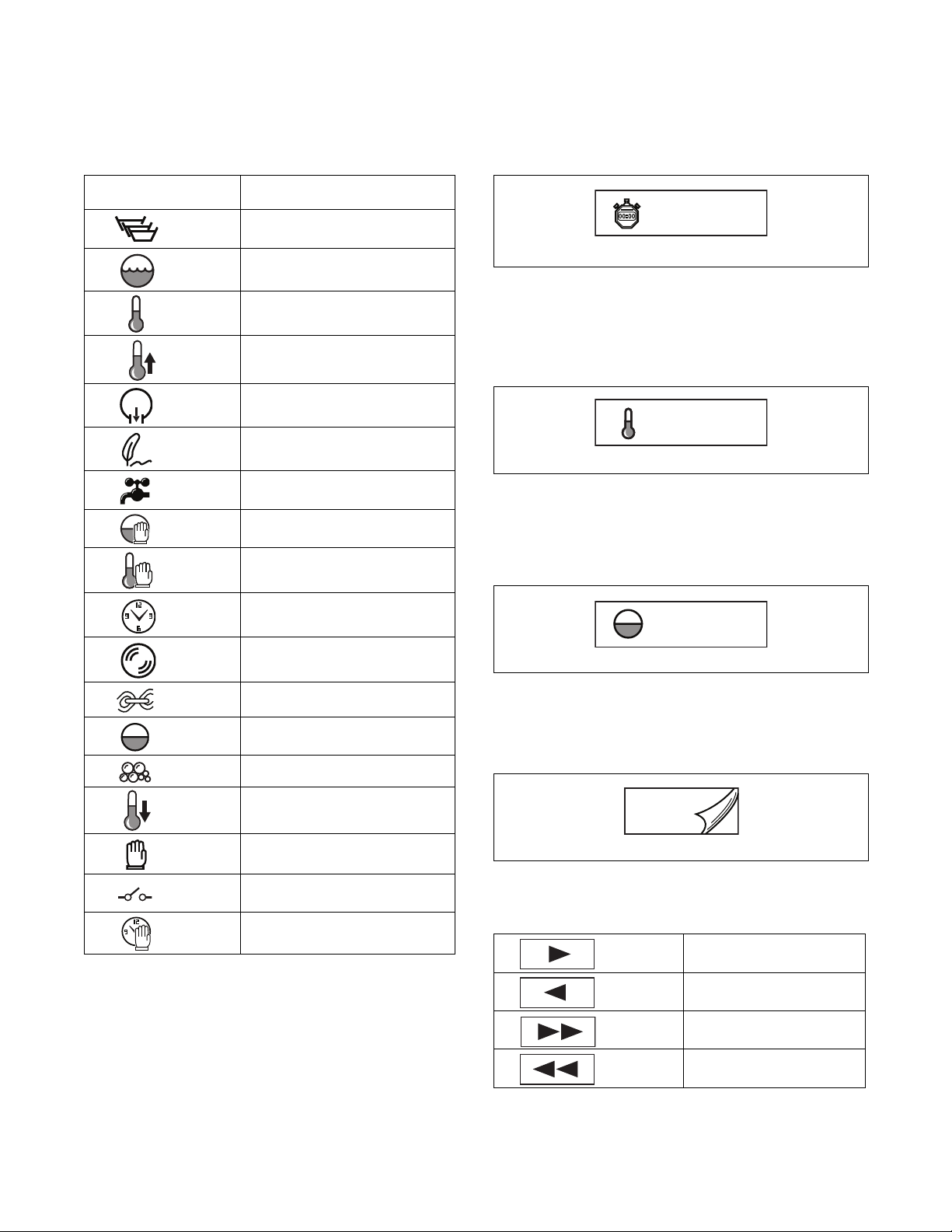
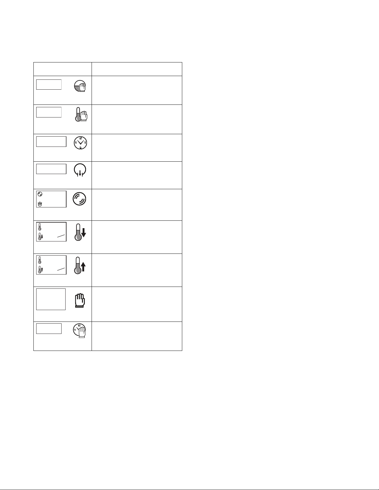
Step Bar (Refer to Figure 2, Item 3)
Displays the phase components. The active component
appears in the selection box.
Symbol Description
CFD206R
CFD207R
CFD208R
CFD209R
CFD210R
CFD211R
CFD213R
CFD214R
CFD215R
Wash Phas e
Wash Action
Heating
Controlled Heating
Drain
Label
Water Inlet
Water Level Time Stop
Heating Time Stop
Cycle Time Remaining
(Refer to Figure 2, Item 4)
Displays the remaining program time.
1h 27
CFD226R
Figure 3
Water Temperature (Refer to Figure 2, Item 5)
Displays the temperature of the water. This symbol is
flashing when heating is activated.
13°C
CFD227R
Figure 4
Water Level (Refer to Figure 2, Item 6)
Displays the water level in the wash tub. This symbol
is flashing when machine is filling.
CFD216R
CFD217R
CFD218R
CFD219R
CFD220R
CFD221R
CFD222R
CFD224R
CFD224R
Time
Spin
Subroutine
Water Level
Soap Inlet
Cool Down
Hold
Relay Contact
Predefined Start
Tab le 2
23.0cm
CFD228R
Figure 5
Next Screen (Refer to Figure 2, Item 7)
View the next screen.
CFD426R
Figure 6
Proceed - Return (Refer to Figure 2, Item 8)
Go to the next component.
CFD261R
Restart the current phase.
CFD423R
Start the next phase.
CFD424R
Resume the previous or first
CFD425R
phase.
Ta bl e 3
D1353 (EN)
© Copyright, Alliance Laundry Systems LLC – DO NOT COPY or TRANSMIT
9
Page 12
Display Identification
1
500
min
rpm
00
40 °C
2.0
°C
min
40 °C
2.0
°C
min
1h59
Explanation
Explanation
Explanation
8:00
Info (Refer to Figure 2, Item 9)
Displays information on the active component:
Symbol Description
15 cm
CFD229R CFD214R
Level Stop: Target level is
displayed.
40 °C
CFD230R CFD215R
12min25
CFD231R CFD216R
1
CFD232R CFD210R
CFD233R CFD217R
CFD234R CFD221R
CFD235R CFD209R
Heat Stop: Target temperature.
Time: Time remaining.
Drain: Selected drain.
Spin: Set spin speed and remaining
spin time.
Cool-down: Target temperature
and drop in temperature per minute.
Controlled Heating: Ta rget
temperature and rise in temperature
per minute.
CFD236R CFD222R
CFD237R CFD224R
Waiting: Remaining waiting time
and self-composed comment.
Predefined Start: Time at which
the program will start or resume.
Tab le 4
10
© Copyright, Alliance Laundry Systems LLC – DO NOT COPY or TRANSMIT
D1353 (EN)
Page 13

Special Features
Programming Control
The control allows the washer-extractor’s operator to
program the control with the use of the keypad.
For details on programming select cycle options, refer to
the Advanced Functions Sub-menu section.
Viewing Control Information
The control will store information in its memory that
can be retrieved by pressing various combinations of
keypads. The control will record machine cycles and
hours of operation.
For more information, refer to the Logbook Sub-menu
section.
Testing Machine Components
By entering the Non-Active Menu’s Test Menu under
the Advanced Functions Sub-menu, the operator may
perform the following tests:
• Water Level Test
• Water Inlet Test
• Motor Test
• Temperature Sensor Test and Calibration
• Water Outlet Valve or Drain Pump Test
• Expansion Relay Test
• Rotation Sensor Door Lock and Out-Of-Balance
Switch Test
Rapid Advance Feature
This feature allows the operator to manually advance
through an active cycle. This feature is useful when
tests must be performed immediately on a washerextractor currently in an active cycle.
For detailed information on using the Rapid Advance
feature, refer to the Rapid Advance Feature section.
Communication Mode
This feature allows the control to communicate with a
PC equipped with the Cygnus Assist software using
infra-red communication. This allows the control to be
programmed and have its data read without using the
machine’s keypad.
For more detailed information on using the
Communication Mode feature, refer to the
Communication Mode section.
For detailed information, refer to the Test Menu
section under the Advanced Functions Sub-menu.
D1353 (EN)
© Copyright, Alliance Laundry Systems LLC – DO NOT COPY or TRANSMIT
11
Page 14

Washer-Extractor Operation
Start Up
When power is applied to the washer-extractor, if the
control was not powered down during a running cycle,
it will enter Start Mode.
Start Mode
The control enters this mode when the machine is ready
for operation. The display will show the available
cycles.
After pressing the Start/Stop keypad with the door
closed and locked, the cycle will begin.
Run Mode
Upon the start of a cycle, the control displays detailed
information about the cycle and current phase.
Stop Mode
The control enters this mode if the operator ends the
cycle before it is completed by pressing the Start/Stop
keypad. Once the control does not detect water or
cylinder rotation, it will enter End of Cycle mode.
End of Cycle Mode
When a cycle is complete, the control will display
“End” until the door is opened. When the door is
opened, the control will return to Start Mode.
12
© Copyright, Alliance Laundry Systems LLC – DO NOT COPY or TRANSMIT
D1353 (EN)
Page 15
The Non-Active Menu
1
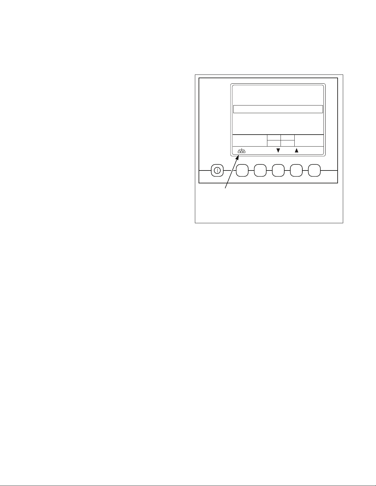
What is Available in the Non-Active
Menu?
The Non-Active menu can be used to obtain
information from the machine, run test cycles, modify
the control’s programmable features, set the service
counters and view the error code history.
NOTE: To enter the Non-Active Menu, a cycle must
not be in process.
To enter the Non-Active Menu, press and hold the
keypad below the Menu icon.
Normal wash 40º-40ºC
War m wash 30º-60ºC
Hot wash 30º-90ºC
Delicate 30ºC
Synthetic 1 40ºC
1h00
CFD937R
CFD937R
1
Menu
Figure 7
D1353 (EN)
© Copyright, Alliance Laundry Systems LLC – DO NOT COPY or TRANSMIT
13
Page 16
The Non-Active Menu
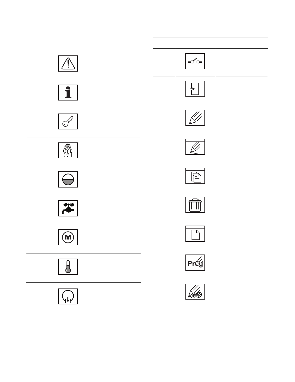
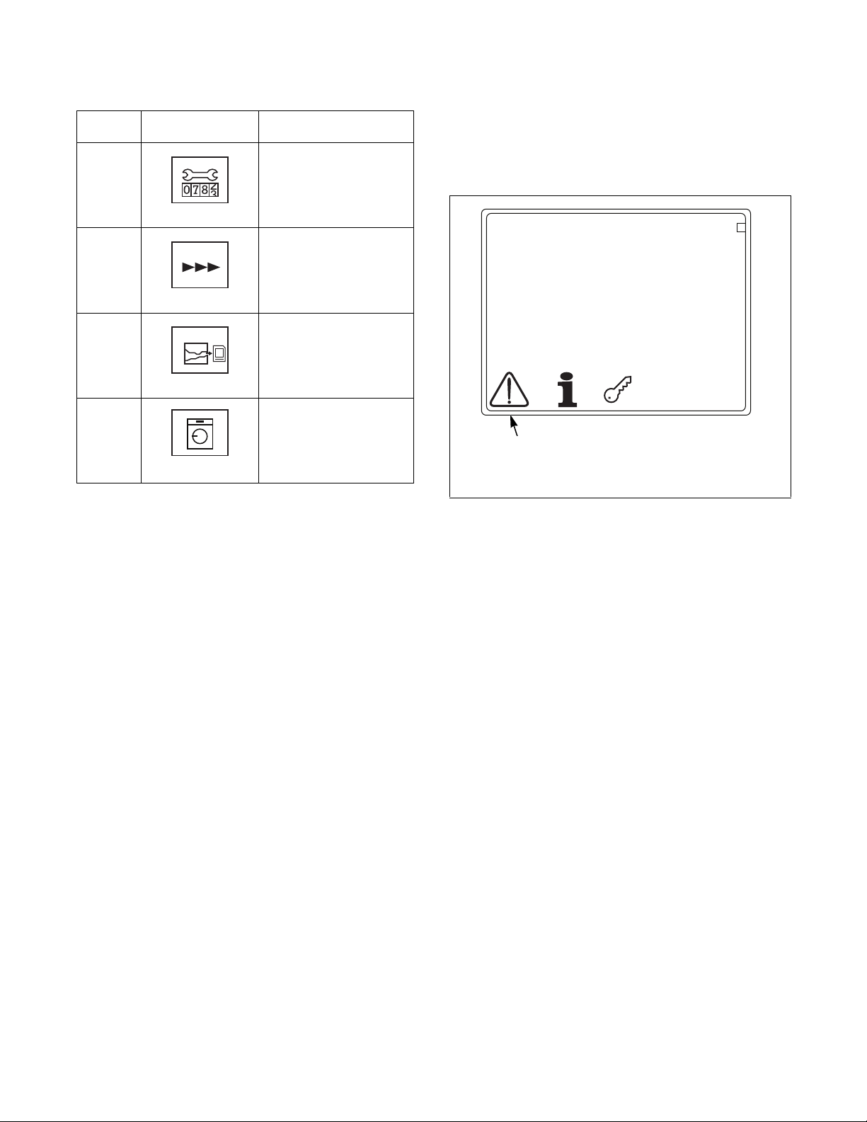
Non-Active Menu Navigation
Option
Number
1
2
3
a.
i.
Option
Icon
CFD272R
CFD275R
CDF284R
CFD293R
Logbook Sub-Menu:
displays information
about cycles that have
been run.
Info Sub-Menu: displays
technical information
about the machine,
configurations and cycle
programs.
Advanced Functions
Sub-Menu: run test
program, create or edit
cycle programs.
Tes t Me nu : test operation
of certain electrical
components
Water Level Sensor: set
0 level and calibrate
Description
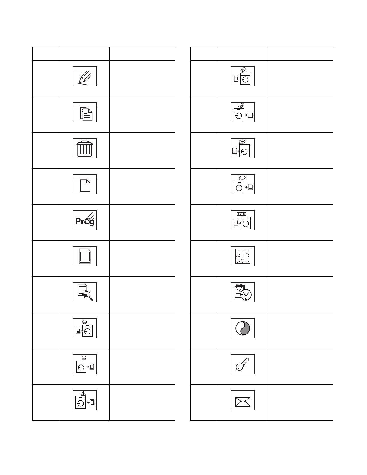
Option
Number
vii.
b.
vi.
ii.
(Continued Table 5)
Option
Icon
Description
Expansion Relay:
activate the (optional)
expansion relay
CFD327R
Inputs: test inputs
CFD329R
Edit Menu: create, edit,
copy or delete cycle
programs
CFD333R
Edit Program
i.
CFD335R
Copy Program
ii.
iii.
iv.
CFD296R
Water Inlet Valves:
activate valves
CFD300R
iii.
Motor: test motor and
frequency inverter
CFD308R
iv.
Temperature Sensor:
test sensor
CFD319R
v.
Water Outlet Valve or
Pump: test operation and
v.
CFD323R
seal of valves or pump
c.
(Continued Table 5)
CFD336R
Delete Program
CFD337R
Create Program
CFD338R
Modify Program Title
CFD339R
Edit Menu Subroutine:
create, edit, copy or delete
subroutines
CFD376R
(Continued Table 5)
14
© Copyright, Alliance Laundry Systems LLC – DO NOT COPY or TRANSMIT
D1353 (EN)
Page 17
The Non-Active Menu
Option
Number
d.
iii
iv.
(Continued Table 5)
Option
Icon
Edit Subroutine
Description
Option
Number
(Continued Table 5)
Option
Icon
Upload Price and Time
Description
File to Machine: load
i.
CFD385R
v.
CFD398R
Copy Subroutine
price and time file
Download Price and
Time File from
ii
vi.
Machine: write price and
time files to data card
CFD386R
Delete Subroutine
CFD401R
Upload Help File to
Machine: load help file to
machine
Download Help File
CFD387R
vii.
CFD402R
Create Subroutine
from Machine: write help
file to data card
Upload Firmware
CFD338R
viii.
CFD403R
Modify Subroutine Title
(*.csp) to Machine: load
v.
ix.
firmware and updates to
machine
CFD339R
Data Transfer Menu:
upload software or
download data from the
e.
CFD404R
Setting Menu: edit user
settings
machine using a data card
CFD379R
Content of Data Card:
CFD405R
Date and Time
read content of data card
i.
i.
D1353 (EN)
ii.
iii.
iv.
CFD385R
Upload Wash Data to
Machine: load cycle
programs to machine
CFD392R
Download Wash Data
form Machine: write
cycle programs to data
card
CFD395R
Download Logbook
from Machine: write
logbook contents to data
card
CFD397R
(Continued Table 5)
© Copyright, Alliance Laundry Systems LLC – DO NOT COPY or TRANSMIT
CFD408R
Display: contrast
ii.
CFD410R
Password/Access Code:
change access code
iii.
CFD284R
Address: set network
address number
iv.
CFD413R
(Continued Table 5)
15
Page 18
The Non-Active Menu
12oC
20
10
0
CFD271R
2
1
Option
Number
vii.
viii.
vi.
(Continued Table 5)
Option
Icon
Description
Maintenance Counters:
set maintenance warning
v.
CFD415R
times
Non-Active Menu Options
1. Logbook Sub-Menu
The Logbook Sub-Menu allows the operator to view
information about cycles that have been run.
Advance: activate/
deactivate rapid advance
CFD419R
History Overview
(graph): write to a data
card
CFD420R
Put Out of Order:
disable machine
CFD271R
CFD421R
1 Logbook Sub-Menu
Tab le 5
Figure 8
To access the Logbook Sub-Menu, press the keypad
below the Logbook Sub-Menu icon. Refer to Figure 8.
16
© Copyright, Alliance Laundry Systems LLC – DO NOT COPY or TRANSMIT
D1353 (EN)
Page 19

CFD935R
CFD935R
?
Time Date Event Prog
15:46
15:46
15:43
15:43
15:41
15:41
15:40
15:40
15:38
10/09
10/09
10/09
10/09
10/09
10/09
10/09
10/09
10/09
159
159
102
100
159
159
159
159
159
03
03
03
03
01
01
01
01
01
0001
0002
0003
0005
0006
0007
0008
0009
0010
007
Injector communication error
#
15:43 10/09 007 030004
2
1
7: Inverter communication error
Error during communication with
invertor:
- no communication / reaction from
the mainboard
- missing communication between
inverter and mainboard
- check connection and
wiring with inverter board
- check functioning inverter board
(art.209/02006/00)
CFD271R
2
1
1 Navigation
2 Call Info
Figure 9
The overview shows the history of a cycle program.
# Number of the event
Time: Time of the event
Date: Date of the event
Event: Indication of the specific event (see page 53)
The Non-Active Menu
2. Info Sub-Menu
The Info Sub-Menu allows the operator to view
technical information about the machine,
configurations and cycle programs.
CFD271R
1 Info Sub-menu
Figure 11
To access the Info Sub-Menu, press the keypad below
the Info Sub-Menu icon. Refer to Figure 11.
Prog: Program number
Select an action using the keypads below the
Navigation icons and press keypad below the Call Info
icon. Action details will be displayed.
Press the Start/Stop keypad to return.
D1353 (EN)
CFD938R
Figure 10
© Copyright, Alliance Laundry Systems LLC – DO NOT COPY or TRANSMIT
17
Page 20

The Non-Active Menu
CFD276R
Software
Package
Mainboard
Boot
Display
Boot
Washdata
Machine info
D. O. M.
D. O. I.
Type
Serial nr
Counters
Cycles
Hours
Freestanding
:
:
:
:
:
:
:
:
:
:
:
1/2007
0H6 (HC165)
1002
:
:
: yes
4987
48553
V 1 . 3 . 3
V 1 . 3 . 3
V 1 . 3 . 3
V 1 . 3 . 3
V 1 . 3 . 3
HC165 PROF 1-16 r e l a . cgs
*
18/02/2011, at 08:55
1/7
CFD276R
CFD277R
:
:
:
:
:
:
:
:
:
:
:
:
:
Configuration 1
Capacity
Diam tub
Depth tub
Diam drum
Level offset
Min level
Overflow level
Motor voltage
Motor power
Heat 1 : electric
Heat 2 : none
Min spin speed
Max spin speed
16.5 kg
710 mm
565 mm
650 mm
-90 mm
130 mm
405 mm
230 v
1500 v
( 10 kw )
250 rpm
1000 rpm
2/7
CFD277R
CFD278R
:
:
:
:
:
:
:
:
:
:
:
:
:
:
:
Configuration 2
Max current
Stall prev wash
Stall prev jump
Stall prev spin
Max prev
Prev ratio
Prev offset
Stall ratio
Wash accel
Wash accel
Dist accel
Jump accel
Spin accel
Spin accel
Pulses/rev
6.5 A
140 A
63 A
68 A
165 Hz
15.00 Hz / 100 rpm
1.00 Hz
16.58 Hz / 100 rpm
5 s/50Hz
8 s/50Hz
40 s/50Hz
25 s/50Hz
0.75 Hz/g
40 s/50Hz
3
3/7
CFD278R
CFD279R
Hints : edited - measured
Prog
Prog
Prog
Prog
Prog
Prog
Prog
Prog
Prog
Prog
Prog
Prog
Prog
Prog
Prog
Prog
Prog
Prog
Prog
Prog
4:15
4:15
4:15
4:15
4:15
4:15
4:15
4:15
4:15
4:15
4:15
4:15
4:15
4:15
4:15
4:15
4:15
4:15
4:15
4:15
0.00
0.00
0.00
0.00
0.27
0.00
0.00
0.00
0.00
0.00
0.22
0.00
0.00
0.00
0.00
0.00
0.00
0.00
0.00
0.00
1:
2:
3:
4:
5:
6:
7:
8:
9:
10:
11:
12:
13:
14:
15:
16:
17:
18:
19:
20:
4/7
CFD279R
Screen 1/7:
Software version
Machine info (date of manufacture, serial number, etc.) and
counters
Press the keypads below the Navigation icon to view the next or previous
screen.
Press the Start/Stop keypad to return.
Screen 2/7:
Configuration 1
Machine configuration
Press the keypads below the Navigation icons to view the next or previous
screen.
Press the Start/Stop keypad to return.
Screen 3/7:
Configuration 2
Data relating to the frequency inverter.
Press the keypads below the Navigation icons to view the next or previous
screen.
Press the Start/Stop keypad to return.
Screen 4/7:
Edited and measured times of the cycle programs.
(Continued Table 6)
18
© Copyright, Alliance Laundry Systems LLC – DO NOT COPY or TRANSMIT
D1353 (EN)
Page 21

The Non-Active Menu
CFD280R
5/7
Hints : edited
Prog
Prog
Prog
Prog
Prog
Prog
Prog
Prog
Prog
Prog
Prog
Prog
Prog
Prog
Prog
Prog
Prog
Prog
Prog
Prog
4:15
4:15
4:15
4:15
4:15
4:15
4:15
4:15
4:15
4:15
4:15
4:15
4:15
4:15
4:15
4:15
4:15
4:15
4:15
4:15
21:
22:
23:
24:
25:
26:
27:
28:
29:
30:
31:
32:
33:
34:
35:
36:
37:
38:
39:
40:
CFD280R
CFD281R
6/7
Hints : edited
Prog
Prog
Prog
Prog
Prog
Prog
Prog
Prog
Prog
Prog
Prog
Prog
Prog
Prog
Prog
Prog
Prog
Prog
Prog
Prog
4:15
4:15
4:15
4:15
4:15
4:15
4:15
4:15
4:15
4:15
4:15
4:15
4:15
4:15
4:15
4:15
4:15
4:15
4:15
4:15
41:
42:
43:
44:
45:
46:
47:
48:
49:
40:
51:
52:
53:
54:
55:
56:
57:
58:
59:
60:
CFD281R
CFD282R
7/7
Weekly program counter
Pr
Pr
Pr
Pr
Pr
Pr
Pr
Pr
Pr
Pr
Pr
Pr
Pr
Pr
Pr
Pr
Pr
Pr
Pr
Pr
0
0
1
1
0
0
4
0
0
0
0
0
0
0
0
0
0
0
0
0
1:
2:
3:
4:
5:
6:
7:
8:
9:
0:
11:
12:
13:
14:
15:
16:
17:
18:
19:
20:
Pr
Pr
Pr
Pr
Pr
Pr
Pr
Pr
Pr
Pr
Pr
Pr
Pr
Pr
Pr
Pr
Pr
Pr
Pr
Pr
0
0
0
0
0
0
0
0
0
0
0
0
0
0
0
0
0
0
0
0
21:
22:
23:
24:
25:
26:
27:
28:
29:
30:
31:
32:
33:
34:
35:
36:
37:
38:
39:
40:
Pr
Pr
Pr
Pr
Pr
Pr
Pr
Pr
Pr
Pr
Pr
Pr
Pr
Pr
Pr
Pr
Pr
Pr
Pr
Pr
0
0
0
0
0
0
0
0
0
0
0
0
0
0
0
0
0
0
0
0
41:
42:
43:
44:
45:
46:
47:
48:
49:
50:
51:
52:
53:
54:
55:
56:
57:
58:
59:
60:
0
CFD282R
CFD283R
CFD283R
(Continued Table 6)
Screen 5/7:
Edited and measured times of the cycle programs (continued).
Screen 6/7:
Edited and measured times of the cycle programs (continued).
Screen 7/7:
Overview of the weekly counts per cycle (the number of times that each
cycle has been executed during the last 7 days).
Press the keypad below the 0 in order to reset the counters.
Press the keypad below the Check icon to confirm the reset, or press the
keypad below the X to cancel.
Tab le 6
D1353 (EN)
© Copyright, Alliance Laundry Systems LLC – DO NOT COPY or TRANSMIT
19
Page 22

The Non-Active Menu
CFD271R
2
1
1000_
3. Advanced Functions Sub-Menu
The Advanced Functions Sub-Menu allows the
operator to test machine components, create or edit a
cycle or modify the machine’s settings.
CFD271R
1 Advanced Functions Sub-Menu
Figure 12
To access the Advanced Functions Sub-Menu, press
the keypad below the Advanced Functions Sub-Menu,
icon. Refer to Figure 12.
“Advanced functions” Access Code Menu
The operator must have the security code to access
advanced functions.
Enter the password using the keypads below the
Navigation icons and press the keypad below the
Check icon to confirm.
CFD285R
Figure 13
The security code is 1000 by default.
The Advanced Functions Sub-Menu is now displayed.
Press the Start/Stop keypad to return.
20
© Copyright, Alliance Laundry Systems LLC – DO NOT COPY or TRANSMIT
D1353 (EN)
Page 23

The Non-Active Menu
CFD292R
3
54321
CFD294R
4
54321
6
7 8 5
3.1 Test Menu
1 Test Menu
2 Edit Menu: Edit, copy or delete cycle
programs (see page 28).
3 Edit Menu Subroutine: Edit, copy or delete
subroutines (see page 34).
4 Data Transfer Menu: Upload software or
download data from the machine using a data
card (see page 35).
5 Settings Menu: Edit the user setting
(see page 44).
The Test Menu allows the operator to test the operation
of certain electrical components of the machine.
To access the Test Menu from the Advanced Functions
Sub-Menu, press the keypad below the corresponding
icon.
NOTE: Empty the drum completely before running
the test program.
CFD292R
Figure 14
5
CFD239R
CFD294R CFD939R
1 Water Level Sensor (see page 22) 5 Navigation
2 Water Inlet Valves (see page 22) 6 Water Outlet Valve or Pump (see page 25)
3 Motor (see page 23) 7 Expansion Relay (see page 25)
4 Temperature Sensor (see page 24) 8 Inputs (see page 26)
Figure 15
D1353 (EN)
© Copyright, Alliance Laundry Systems LLC – DO NOT COPY or TRANSMIT
21
Page 24

The Non-Active Menu
4
WATER LEVEL SENSOR
CFD297R
440
44.5 rpm
0.0 cm
0
CFD297R
CFD298R
440
4.0 cm
44.5 rpm
CFD298R
Measured
Level
Theoretical
Level
CFD299R
4
WATER INLET VALVES
HOT 1
CFD301R
CFD302R
CFD303R
CFD304R
CFD305R
CFD306R
CFD307R
Advanced Functions Sub-Menu/Test Menu/
Water Level Sensor
CFD294R
Figure 16
To access the Water Level Sensor display, from the
Test Menu, press the keypad below the corresponding
icon. Refer to Figure 16.
Allows the operator to set the zero level and calibrate
the water level sensor.
Setting the Zero Level
Make sure all the water has been
emptied.
If necessary, stop the power to the
machine for a few minutes.
Then press the keypad below the 0
to establish the “zero level”.
Calibrating the Sensor
To do this, first place a marker in
the middle of the door window.
Then press the keypad below the
Water Inlet icon to fill the
machine. Press the keypad again
to stop filling when the water
reaches the marker.
Compare the measured level
against the theoretical level and, if
44.5 rpm
44.5 cm
necessary, adjust the measured
439
value using the keypads below the
Navigation icons and confirm by
presing the keypad below the
Check icon.
CFD299R
Press the Start/Stop keypad to exit
this test.
Tab le 7
Advanced Functions Sub-Menu/Test Menu/
Water Inlet Valves
CFD294R
Figure 17
To access the Water Inlet Valves display, from the Test
Menu, press the keypad below the corresponding icon.
Refer to Figure 17.
Allows the operator to activate the water inlet valves.
Use the keypads below the
Navigation icons to select one
or more valves and press the
keypad below the Check icon
to activate the selected valve.
Press the Start/Stop keypad to
exit this test.
Hot water - pre-wash
compartment
Hot water - softener
compartment
Hot water - main wash
compartment
Cold water - pre-wash
compartment
Cold water - bleach
compartment
Cold water - main wash
compartment
22
Ta bl e 8
© Copyright, Alliance Laundry Systems LLC – DO NOT COPY or TRANSMIT
D1353 (EN)
Page 25

The Non-Active Menu
4
MOTOR
0
rpm
frequency : 0.00 Hz
current : 0.00 A
voltage : 0.0 V
FR D720
0.4 KW
1 2
3
CFD310R
44
rpm
frequentie: 6.35 Hz
current : 3.13 A
CFD310R
CFD311R
45
rpm
frequentie : 6.50 Hz
current : 3.11 A
on / off : 90/350 msec (20%)
CFD311R
CFD312R
CFD313R
Spin
Speed
Spin
Time
CFD315R
306
rpm
CFD315R
Advanced Functions Sub-Menu/Test Menu/
Motor
CFD294R
Figure 18
To access the Motor display, from the Test Menu, press
the keypad below the corresponding icon. Refer to
Figure 18.
Allows the operator to test the operation of the motor
and frequency inverter.
Checking the wash speed
Checking the spin speed
265
rpm
500
rpm
ratio : 1443
27.8g _ 40.50Hz _ 2.92A
500
rpm
500
rpm
ratio : 1418
90.6g _ 70.90Hz _ 2.09AA
1
0
Press the keypad below the Wash
icon (refer to Figure 14) to bring
the drum up to wash speed.
Press the keypad below the
Rotation icon (as shown).
The system will display the time it
takes the rotation sensor to detect
a spoke of the belt pulley.
on = detect
off = do not detect
The system also displays the
detection ratio as a percentage.
Press the keypad below the Spin
Speed icon (refer to Figure 19) to
bring the drum to a spin speed of
500 rpm.
mm56
If the machine has a maximum
spin speed of less than 500 rpm,
CFD312R
this number will be rounded down
to the nearest lower one hundred.
Once the drum has spun for a few
seconds at 500 rpm (to measure
the revolution frequency ratio),
press the keypad below the left
mm07
Up/Down icons to increase the
spin speed (depending on the
machine type).
CFD313R
Press the keypads below the right
Up/Down icons to adjust the spin
time, if necessary.
Once the spin time has passed, the
drum will slow down and the spin
speed will be displayed.
D1353 (EN)
1 Wash
2 Spin Speed
3 Inverter
(Continued Table 9)
Figure 19
CFD940R
© Copyright, Alliance Laundry Systems LLC – DO NOT COPY or TRANSMIT
23
Page 26

The Non-Active Menu
CFD317R
Resetting invertor...
CFD317R
CFD318R
Auto tuning in progress...
CFD318R
4
TEMPERATURE SENSOR
CFD320R
21 oC
100%
CFD320R
CFD321R
CFD322R
(Continued Table 9)
Tuning the frequency invertor to the motor
This will need to be performed
every time a new motor or
frequency invertor is fitted.
Press the keypad below the
Inverter icon to start the
adjustment. Refer to Figure 19.
The frequency invertor is first
reset (Resetting invertor...), then
the motor and invertor are tuned
(Auto tuning in progress...).
Press the Start/Stop keypad to exit
the motor test.
Table 9
Advanced Functions Sub-Menu/Test Menu/
Temperature Sensor
CFD294R
Figure 20
To access the Temperature Sensor display, from the
Test Menu, press the keypad below the corresponding
icon. Refer to Figure 20.
Allows the operator to test the operation of the
temperature sensor.
Press the keypad below the
Water Inlet icon (as shown) to
start the test.
The temperature measured by
the sensor is displayed.
Water will fill until it reaches
the safety level.
19 oC
100%
The Heat icon will appear (as
shown).
CFD321R
Press the keypad below the Heat
icon to switch the heating
elements on or off.
30 oC
While the heating elements are
100%
on, the temperature will reach a
maximum of 90°C.
CFD322R
Press the Start/Stop keypad to
exit this test.
Table 10
24
© Copyright, Alliance Laundry Systems LLC – DO NOT COPY or TRANSMIT
D1353 (EN)
Page 27

The Non-Active Menu
WATER INLET VALVES
5
WATER OUTLET VALVE OR PUMP
CFD324R
0.0 cm
1 2
CFD324R
CFD325R
CFD326R
22.5 cm
1 2
CFD326R
WATER INLET VALVES
5
EXPANSION RELAY
O Clax Activ
O Clax Star
O Eco Star
O Eco Break
O Flashing lig
O Horn
O Lanadol
O Clip Combi
O Viva Deo Plu
O Potan Ole
O Recy. Pump
O No function
O No function
Advanced Functions Sub-Menu/Test Menu/
Water Outlet Valve or Drain Pump
CFD939R
Figure 21
To access the Water Outlet Valve or Drain Pump
display, from the Test Menu, press the keypad below
the corresponding icon. Refer to Figure 21.
Allows the operator to test the operation and seal of the
outlet valves or pump.
Advanced Functions Sub-Menu/Test Menu/
Expansion Relay
CFD939R
Figure 22
To access the Expansion Relay display, from the Test
Menu, press the keypad below the corresponding icon.
Refer to Figure 22.
Allows the operator to activate the (optional)
expansion relay.
11.5 cm
1 2
The water level is displayed.
Press the keypad below the
Water Inlet (as shown) icon to
fill the tub.
Press again to stop filling.
CFD326R
Press the keypad below the 1 or
2 (option) to allow the tub to
empty (drain symbol appears).
Press this keypad again to stop
the tub from emptying.
Press the Start/Stop keypad to
exit the outlet test.
Table 11
CFD328R
Figure 23
Use the keypads below the Navigation icons to select
one or more expansion relays and activate each one
using the keypad below the Checkbox icon. Refer to
Figure 23.
Press the Start/Stop keypad to exit the relay test.
D1353 (EN)
© Copyright, Alliance Laundry Systems LLC – DO NOT COPY or TRANSMIT
25
Page 28

The Non-Active Menu
5
INPUTS
rotation:
tilt:
door:
lock:
1
3 6
2
5
4
CLOSED
OPEN
Advanced Functions Sub-Menu/Test Menu/
Inputs
CFD939R
Figure 24
To access the Inputs display, from the Test Menu, press
the keypad below the corresponding icon. Refer to
Figure 24.
Allows the operator to test the inputs.
An input contact is displayed as open or closed,
depending on its current status. Refer to Figure 26.
CFD331R
Figure 26
Test the inputs
1. Door closed input: while observing the Door
Relay display (refer to Figure 25), open and close
the machine’s door. The Door Relay display
should change from close to open as the door is
opened and from open to close as the door is
closed.
Door lock input: close the machine’s door.
While observing the Lock Switch display (refer
to Figure 25), press the keypad below the Door
Lock icon (refer to Figure 25), to lock and unlock
the door. The Lock Switch display should change
from open to close as the door is locked and close
to open as the door is unlocked.
Tilt input: while observing the Tilt Switch
display (refer to Figure 25
), manually move the
tilt switch. The Tilt Switch display should change
from close to open as the tilt switch comes into
contact with the cutout in the tilt switch bracket.
1 Door Relay
2 Lock Switch
3 Lock Door
4 Tilt Switch
5 Rotation Sensor
6 Next
Figure 25
2. Rotation input: open the machine’s door. While
observing the Rotation Sensor display (refer to
Figure 25
), manually rotate the machine’s basket.
The Rotation Sensor display should change from
open to close as the basket is rotated and the
RPM sensor detects a pulley spoke.
Press the Start/Stop keypad to exit the inputs test.
CFD330R
© Copyright, Alliance Laundry Systems LLC – DO NOT COPY or TRANSMIT
26
D1353 (EN)
Page 29

Input Relay Card
INPUTS
In 1
In 10
In 7
In 5
In 4
No function
CFD332R
Figure 27
Press the keypad below the Next icon to view the Input
Relay Card display. More or less inputs may be
displayed, depending on the model of machine.
When an input is activated, “●” is displayed. When an
input is not activated, “
○” is displayed.
The Non-Active Menu
D1353 (EN)
© Copyright, Alliance Laundry Systems LLC – DO NOT COPY or TRANSMIT
27
Page 30

The Non-Active Menu
CFD292R
3
EDIT MENU
Thermal Dis./Sluice 75
o
Hot with Prewash 60oC
Fast Hot 60
o
C
Chemical Sluice 40
o
C
Warm with Prewash 40
Warm wash 40
o
C
1
2
3
CFD335R
CFD336R
CFD337R
CFD338R
CFD339R
3.2 Edit Menu
CFD292R
Figure 28
To access the Edit Menu, from the Advanced Functions
Sub-Menu, press the keypad below the corresponding
icon. Refer to Figure 28.
Allows the operator to create, edit, copy or delete cycle
programs.
Edit, copy, delete or create a cycle program
1. Select a program to edit by pressing the keypads
below the Navigation icons. Refer to Figure 29.
2. Press the keypad below the Function Option icon
to change the function. Refer to Tab l e 12 .
Edit a program (see page 29)
Copy a program (see page 32)
Delete a program (see page 32)
Create a new program (see page 33)
Modify a program title (see page 33)
1 Function Option
2 Navigation
3 Check
Figure 29
Table 12
3. Press the keypad below the Check icon to
confirm the function. Refer to Figure 29.
4. When finished editing, press the Start/Stop
keypad to exit the Edit Menu.
CFD533R
CFD375R
Figure 30
Confirm to save any changes made by pressing the
keypad below the Check icon, or cancel by pressing the
keypad below the X. Refer to Figure 30.
28
© Copyright, Alliance Laundry Systems LLC – DO NOT COPY or TRANSMIT
D1353 (EN)
Page 31

Edit Menu/Edit Program
Warm Wash 30 -60oC
Synthetic 1 40
o
C
60
o
C
25
o
C
Synthetic 2
Handwash
Delicate
Hot Wash 30 -90oC
30
o
C
2
3
1
1
2
3
5
6
7
8
4
CFD942R
1 Function Option
2 Navigation
3 Check
Figure 31
To access the Edit Program function, from the Edit
Menu display, press the keypad below the Function
Option until the Edit Program icon appears (as shown).
Press the keypad below the Check icon. Refer to
Figure 31.
The Non-Active Menu
Delicate 30oC
CFD943R
CFD943R
1 Function Option
2 Navigate Phases
3 Navigate Steps
4 Check
5 Title Bar
6 Program Phase Bar
7 Step Bar
8 Edit Field
Figure 32
Allows the operator to edit the selected cycle program.
All values for water level, water temperature, wash
movement, etc., can be changed. The operator can also
add, move or delete cycle phases and steps.
D1353 (EN)
© Copyright, Alliance Laundry Systems LLC – DO NOT COPY or TRANSMIT
29
Page 32

The Non-Active Menu
CFD335
CFD343
CFD344
CFD345
CFD347
Edit program steps
1. Press the keypads below the Navigate Phases
icons until the correct phase is highlighted in the
Program Phase Bar.
2. Press the keypads below the Navigate Steps icons
until the correct step is highlighted in the Step
Bar.
3. Press the keypad below the Function Option to
change the function. Refer to Figure 13.
Edit settings for the selected step
Delete the selected step
Insert a step before the selected step
4. Press the keypad below the Check icon to
confirm the function.
Insert a step behind the selected step
Move the selected step
Table 13
30
© Copyright, Alliance Laundry Systems LLC – DO NOT COPY or TRANSMIT
D1353 (EN)
Page 33

The Non-Active Menu
CFD348R
CFD348R
CFD349R
HOT 1
CFD349R
15 cm
CFD350R
CFD351R
12
.sec
3
.sec
43
rpm
CFD351R
CFD352R
15 cm
CFD352R
0min25
OClax Activ
OClax Star
OEco Star
OEco Break
OLanadol
OClip Combi
OViva Deo Plu
OPotan Ole
Flashing lig
Horn
Recy. pump
Relais 12
Relais 13
Relais 14
Relais 15
Relais 16
CFD353R
CFD354R
40 oC
CFD354R
CFD355R
40 oC
CFD355R
CFD356R
40 oC
0.1
oc
mm
CFD356R
CFD357R
40 oC
1.0
oc
mm
CFD357R
CFD358R
CFD359R
0h10
Explanation 1
CFD359R
R
CFD360R
R
dist
1
CFD361R
CFD255R
O Clax Activ
O Clax Star
O Eco Star
O Eco Break
O Flashing lig
O Horn
O Lanadol
O Clip Combi
O Viva Deo Plu
O Potan Ole
O Recy. Pump
O No function
O No function
CFD362R
CFD363R
Hot Wash 40 -90oC
Label
CFD363R
1
CFD364R
R
CFD365R
Edit step values
Every step has its own values which can be selected
and changed as shown using the selection keypads
(refer to Figure 32.)
Description of the values for each step
Description of the values for each step
Wash phase:
Indication of the step.
Water inlet:
The water inlet valves.
Water level:
The water level and loaddependent filling.
Wash action:
The wash action time, the wash
stop time and the wash speed.
Water level time stop:
The water level to be reached
before the cycle program
continues.
Soap inlet:
The soap inlets via the powder
tray and activation of the liquid
soap pumps (time).
Heating:
The target temperature for the
tub and controlled fill via hot
and cold water mix.
(Continued Table 14)
Time:
The duration of the last step.
13min00
CFD358 R
Wai ting:
The time during which the cycle
program will temporarily stop
and the explanation.
Drain:
The drain valve or drain pump.
1
CFD360
Spin:
500
rpm
1min00
11
CFD361
Relay contact:
The number of relay contacts
available.
Comment:
Info text.
• Spin speed.
• Spin time.
• Maximum number of
attempts to resume spin
after a tilt.
• Wool washing: immediate
start with distribution speed
in the spin cycle.
• Outlet valve: selection of
outlet valve 1 or 2.
or
• Spin with distribution
speed only.
• Outlet valve: selection of
outlet valve 1 or 2.
D1353 (EN)
Heating time stop:
The temperature the tub has to
reach before the cycle program
continues.
Controlled cool down:
The temperature to which the
tub must drop via controlled
cool down and the speed of
cooling.
Controlled heating:
The temperature to which the
tub must rise via controlled
heating and the speed of
heating.
(Continued Table 14)
© Copyright, Alliance Laundry Systems LLC – DO NOT COPY or TRANSMIT
Subroutine:
The available subroutines.
Programmed start time:
7H30
The time when the program
starts.
CFD365
Table 14
Press the Start/Stop keypad to return to the Edit Menu
display.
31
Page 34

The Non-Active Menu
Warm Wash 30 -60oC
Synthetic 1 40
o
C
60
o
C
25
o
C
Synthetic 2
Handwash
Delicate
Hot Wash 30 -90oC
30
o
C
2
1
3
Starch Cold
Spin
Prg 11
CFD946R
Warm Wash 30 -60oC
Synthetic 1 40
o
C
60
o
C
25
o
C
Synthetic 2
Handwash
Delicate
Hot Wash 30 -90oC
30
o
C
2
1
3
Advanced Functions/Edit Menu/Copy
Program
CFD944R
1 Function Option
2 Navigation
3 Check
Figure 33
To access the Copy Program function, from the Edit
Menu display, press the keypad below the Function
Option until the Copy Program icon appears (as
shown). Press the keypad below the Check icon. Refer
to Figure 33.
Allows the operator to create a new program by
copying a selected program and then editing the copied
program.
Advanced Functions/Edit Menu/Delete
Program
CFD946R
1 Function Option
2 Navigation
3 Check
Figure 35
To access the Delete Program function, from the Edit
Menu display, press the keypad below the Function
Option until the Delete Program icon appears (as
shown). Press the keypad below the Check icon. Refer
to Figure 35.
Allows the operator to delete a selected program.
Figure 34
© Copyright, Alliance Laundry Systems LLC – DO NOT COPY or TRANSMIT
The copy program will be placed at the end of the program
list.
32
CFD370R
CFD945R
Figure 36
Confirm by pressing the keypad below the Check icon
or cancel by pressing the keypad below the X. Refer to
Figure 36.
When this is done, the Edit Menu will appear.
D1353 (EN)
Page 35

The Non-Active Menu
Warm Wash 30 -60oC
Synthetic 1 40
o
C
60
o
C
25
o
C
Synthetic 2
Handwash
Delicate
Hot Wash 30 -90oC
30
o
C
CFD372R
CFD373R
Prg 12
CFD373R
Warm Wash 30 -60oC
Synthetic 1 40
o
C
60
o
C
25
o
C
Synthetic 2
Handwash
Delicate
Hot Wash 30 -90oC
30
o
C
Advanced Functions/Edit Menu/Create New
Program
CFD947R
Figure 37
To access the Create New Program function, from the
Edit Menu display, press the keypad below the
Function option until the Create New Program icon
appears (as shown). Press the keypad below the Check
icon. Refer to Figure 37.
Allows the operator to create a new program.
Advanced Functions/Edit Menu/Modify
Program Title
CFD948R
Figure 38
To access the Modify Program Title function, from the
Edit Menu display, press the keypad below the
Function Option until the Modify Program title icon
appears (as shown). Press the keypad below the Check
icon. Refer to Figure 38.
Allows the operator to modify the title of a program.
The new program will
automatically be placed at the
end of the program list.
The new program has been
given a basic structure of a
default program (2 washes +
3 rinses).
The new program can be edited as described under Edit
Program (see page 29).
NOTE: Modifying the program’s title is only possible
when the text is not a bitmap. When copying or
creating new cycles on the marhine, these cycles will
have a text title. Refer to Figure 34.
D1353 (EN)
© Copyright, Alliance Laundry Systems LLC – DO NOT COPY or TRANSMIT
33
Page 36

The Non-Active Menu
CFD292R
3
EDIT MENU SUBROUTINE
Sub 01
Sub 02
Sub 03
1
3
2
CFD335R
CFD336R
CFD337R
CFD338R
CFD339R
3.3 Edit Menu Subroutine
CFD292R
Figure 39
To access the Edit Menu Subroutine, from the
Advanced Functions Sub-Menu, press the keypad
below the corresponding icon. Refer to Figure 39.
Allows the operator to edit, copy, delete or create new
subroutines. A subroutine is a block of steps grouped
together for insertion into a program. This enables the
operator to create programs faster by placing identical
program phases (such as rinses) in a subroutine.
Edit, copy, delete or create a subroutine
1. Select a subroutine to edit by pressing the kepads
below the Navigation icons. Refer to Figure 40.
2. Press the keypad below the Function Option to
change the function. Refer to Figure 40 and
Tab l e 15 .
Edit subroutine
Copy subroutine
Create a new subroutine
Delete subroutine
Modify a subroutine title
1 Function Option
2 Navigation
3 Check
Figure 40
Table 15
3. Press the keypad below the Check icon to
confirm the function. Refer to Figure 40.
4. Subroutines can be built, edited, copied or
deleted in the same way as wash programs (see
Edit Menu).
However, one subroutine cannot be inserted
into another.
CFD949R
34
© Copyright, Alliance Laundry Systems LLC – DO NOT COPY or TRANSMIT
D1353 (EN)
Page 37

CFD378R
Sub 06
DATA TRANSFER MENU
Figure 41
To create a new subroutine, start a basic subroutine. It
can then be edited in the same way as a cycle program
(see Edit Program).
The steps bar displays the content.
Press the Start/Stop keypad to exit the Edit Subroutine
Menu.
5. Save changes (refer to Figure 41).
The Non-Active Menu
3.4 Data Transfer Menu
3
CFD292R
CFD292R
Figure 42
To access the Data Transfer Menu, from the Advanced
Functions Sub-Menu, press the keypad below the
corresponding icon. Refer to Figure 42.
Allows the user to upload software or download data
from the machine using an SD card.
1. The “insert card” display will appear. Refer to
Figure 43.
# Type Filename Size
CFD381R
Figure 43
2. Put the SD card into the slot at the front of the
control panel. Refer to Figure 44.
CFD380R
Figure 44
If there is no slot, the operator can insert the SD
card into the card holder on the inside of the
control panel. To do this, the operator must
remove the cover from the machine.
D1353 (EN)
© Copyright, Alliance Laundry Systems LLC – DO NOT COPY or TRANSMIT
The Data Transfer Menu will appear. Refer to
Figure 45.
35
Page 38

The Non-Active Menu
CFD382R
3.1
8:09
5432
1
CFD384
3.8
8:09
59876 10
8:09
CEF382R CFD383R CFD384R
3.7
CFD383R
1 Content of data card 7 Write price and time file from the machine to the
2 Write cycle data from the data card to the data card (see page 37).
machine. 8 Write help file from the data card to the machine
3 Write cycle data from the machine to the data (see page 38).
card (see page 35). 9 Write help file from the machine to the data card
4 Write logbook contents to the data card (see page 40).
(see page 36). 10 Write machine firmware (*.csp) from a data card
5 Navigation to the machine (see page 41).
6 Write price and time file from the data card to
the machine (see page 37).
Figure 45
An hourglass symbol will appear while data is being
transfered.
IMPORTANT: Do not remove the SD card while
the hourglass is present.
36
© Copyright, Alliance Laundry Systems LLC – DO NOT COPY or TRANSMIT
D1353 (EN)
Page 39

The Non-Active Menu
CFD382R
3.1
8:09
WRITE DATA TRANSFER
FROM THE MACHINE TO THE DATA CARD
HC165_00000
2
HC165_00000
1
Advanced Functions Sub-Menu/Data
Transfer Menu/Write Cycle Data from the
Machine to the Data Card
CFD382R
Figure 46
To access the Write Data from the Machine to the Data
Card function, from the Data Transfer Menu, press the
keypad below the corresponding icon. Refer to
Figure 46.
Changing the File Name
1. Move the cursor using the keypads below the
Left/Right icons to select a letter or figure or to
add a letter or figure. Refer to Figure 47.
2. Change the letters and figures using the keypads
below the Up/Down icons. Refer to Figure 47.
3. Press the keypad below the Check icon to write
the data to the data card. Refer to Figure 47.
An hourglass symbol will appear while writing.
4. Press the Start/Stop keypad to return to the Data
Transfer Menu.
Allows the operator to write cycle date (cycle
programs) from the machine to the data card.
1 Cycle Data
2 Cursor
Figure 47
The cycle data is displayed as shown. Refer to
Figure 47. If necessary, the name of the file can be
changed.
CFD396R
D1353 (EN)
© Copyright, Alliance Laundry Systems LLC – DO NOT COPY or TRANSMIT
37
Page 40

The Non-Active Menu
CFD382R
3.1
8:09
WRITE LOGBOOK CONTENTS
TO THE DATA CARD
HC165_00000
Advanced Functions Sub-Menu/Data
Transfer Menu/Write Logbook Contents to
the Data Card
CFD382R
Figure 48
To access the Write Logbook Contents to the Data Card
function, from the Data Transfer Menu, press the
keypad below the corresponding icon. Refer to
Figure 48.
Changing the File Name
1. Move the cursor using the keypads below the
Left/Right icons to select a letter or figure or to
add a letter or figure. Refer to Figure 49.
2. Change the letters and figures with using the
keypads below the Up/Down icons. Refer to
Figure 49.
3. Press the keypad below the Check icon to write
the data to the data card. Refer to Figure 49.
An hourglass symbol will appear while writing.
4. Press the Start/Stop keypad to return to the Data
Transfer Menu.
Allows the operator to write the logbook contents from
the macine to the data card.
1 Logbook Content
2 Cursor
Figure 49
The logbook content file is displayed as shown. Refer
to Figure 49. If necessary, the name of the file can be
changed.
CFD529R
38
© Copyright, Alliance Laundry Systems LLC – DO NOT COPY or TRANSMIT
D1353 (EN)
Page 41

Advanced Functions Sub-Menu/Data
3.1
8:09
CONTENT OF DATA CARD
CFD386R
# Type Filename Size
001
002
003
004
005
006
007
1266 kB in 7 file(s)
Free space: 769 kB
WF235 wet clean
HF234 - Initial
HC165 Coin
April 2009
Cygnus 1.2.5
Coin store BXL
Help Francais
10171
10171
8915
23472
1233678
451
10221
II0I0I
CFD386R
DELETE
Several types of data
can be stored.
CFD387R
CFD951R
CFD389R
CFD390R
CFD391R
CFD375R
Transfer Menu/Content of Data Card
CFD382R
Figure 50
To access the Content of Data Card display, from the
Data Transfer Menu, press the keypad below the
corresponding icon. Refer to Figure 50.
The Non-Active Menu
Allows the operator to read the content of the data card.
Refer to Table 16.
Press the keypad below the Delete icon (above) to delete all the data from the data
card. Confirm by pressing the keypad below the Check icon.
Cycle programs (.cgs)
Machine operating software (firmware) (.csp)
History (.chi)
Price and time file (.cpr)
Help file (.chf)
D1353 (EN)
Cancel deletion by pressing the keypad below the X.
Press the Start/Stop keypad to return to the Data Transfer Menu.
Table 16
© Copyright, Alliance Laundry Systems LLC – DO NOT COPY or TRANSMIT
39
Page 42

The Non-Active Menu
CFD383R
3.7
8:09
WRITE HELP FILE FROM THE
DATA CARD TO THE MACHINE
# Type Filename Size
001
002
003
004
38 kB in 4 file(s)
Free space: 7562 kB
New Medic HC165.chf
New Medic WFH150.chf
New Medic WFH65.chf
HC165_00000
10001
10001
9861
10001
CFD383R
3.7
8:09
WRITE PRICE AND TIME FILE FROM THE DATA
CARD TO THE MACHINE
# Type Filename Size
001
002
003
004
38 kB in 4 file(s)
Free space: 7562 kB
New Medic HC165.cpr
New Medic WFH150.cpr
New Medic WFH65.cpr
HC165_00000
10001
10001
9861
10001
Advanced Functions Sub-Menu/Data
Transfer Menu/Write Help File from the Data
Card to the Machine
CFD583R
Figure 51
To access the Write Help File, from the Data Card to
the machine function, press the keypad below the
corresponding icon. Refer to Figure 51.
Allows the operator to load Help files from the data
card to the machine.
Advanced Functions Sub-Menu/Data
Transfer Menu/Write Price and Time File
from the Data Card to the Machine
CFD383R
Figure 53
To access the Write Price and Time File, from the Data
Card to the Machine function from the Data Transfer
Menu, press the keypad below the corresponding icon.
Refer to Figure 53.
Allows the operator to load price and time files from
the data card to the machine.
1. Use the keypads below the Navigation icons to
select the Help file to write to the machine. Refer
to Figure 52.
2. Confirm by pressing the keypad below the Check
icon. Refer to Figure 52.
An hour glass symbol will appear while writing.
3. Press the Start/Stop keypad to return to the Data
Transfer Menu.
40
CFD930R
Figure 52
1. Use the keypads below the Navigation icons to
select the price and time file to write to the
machine. Refer to Figure 54.
2. Confirm by pressing the keypad below the Check
icon. Refer to Figure 54.
An hourglass symbol will appear while writing.
3. Press the Start/Stop keypad to return to the Data
Transfer Menu.
© Copyright, Alliance Laundry Systems LLC – DO NOT COPY or TRANSMIT
CFD530R
Figure 54
D1353 (EN)
Page 43

The Non-Active Menu
CFD383R
3.7
8:09
WRITE PRICE AND TIME FILE FROM THE
MACHINE TO THE DATA CARD
HC165_00000
2
1
Advanced Functions Sub-Menu/Data
Transfer Menu/Write Price and Time File
from the Machine to the Data Card
CFD383R
Figure 55
To access the Write Price and Time File, from the
Machine to the Data Card function from the Data
Transfer Menu, press the keypad below the
corresponding icon. Figure 55.
The price and time file is displayed as shown. If
necessary, the name of the file can be changed.
1. Move the cursor using the keypads below the
Left/Right icons to select a letter or figure or to
add a letter or figure. Refer to Figure 56.
2. Change the letters and figures with using the
keypads below the Up/Down icons. Refer to
Figure 56.
3. Press the keypad below the Check icon to write
the data to the data card. Refer to Figure 56.
An hourglass symbol will appear while writing.
4. Press the Start/Stop keypad to return to the Data
Transfer Menu.
Allows the operator to write price and time files from
the machine to the data card.
1 Price and time file
2 Cursor
Figure 56
CFD531R
D1353 (EN)
© Copyright, Alliance Laundry Systems LLC – DO NOT COPY or TRANSMIT
41
Page 44

The Non-Active Menu
CFD383R
3.7
8:09
WRITE HELP FILE FROM THE
MACHINE TO THE DATA CARD
HC165_00000
1
2
Advanced Functions Sub-Menu/Data
Transfer Menu/Write Help File from the
Machine to the Data Card
CFD383R
Figure 57
To access the Write Help File from the Machine to the
Data Card display, from the Data Transfer Menu, press
the keypad below the corresponding icon. Refer to
Figure 57.
1. Move the cursor using the keypads below the
Left/Right icons to select a letter or figure or to
add a letter or figure. Refer to Figure 58.
2. Change the letters and figures with using the
keypads below the Up/Down icons. Refer to
Figure 58.
3. Press the keypad below the Check icon to write
the data to the data card. Refer to Figure 58.
An hourglass symbol will appear while writing
4. Press the Start/Stop keypad to return to the Data
Transfer Menu.
Allows the operator to load Help files from the Data
Card to a machine.
1 Help file
2 Cursor
Figure 58
The help file is displayed as shown. If necessary, the
name of the file can be changed.
CFD941R
42
© Copyright, Alliance Laundry Systems LLC – DO NOT COPY or TRANSMIT
D1353 (EN)
Page 45

Advanced Functions Sub-Menu/Data
CFD952R
3.8
8:09
WRITE MACHINE FIRMWARE FROM A DATA
CARD TO THE MACHINE
Transfer Menu/Write Machine Firmware from
a Data Card to the Machine
The Non-Active Menu
CFD953R
Figure 60
1. Cancel load and replace by pressing the keypad
below the X. Refer to Figure 60.
CFD952R
Figure 59
To Write Machine Firmware from a Data Card to the
Machine, from the Data Transfer Menu, press the
keypad below the corresponding icon. Refer to
Figure 59.
Allows the operator to load and replace firmware from
the data card to the machine.
2. Confirm by pressing the keypad below the Check
icon. Refer to Figure 60.
3. Press the Start/Stop keypad to return to the Data
Transfer Menu.
D1353 (EN)
© Copyright, Alliance Laundry Systems LLC – DO NOT COPY or TRANSMIT
43
Page 46

The Non-Active Menu
CFD292R
3
SETTINGS MENU
CFD950R
6.2
9.37
4 - 1
5
4321
6
7
8
5
3.5 Settings Menu
CFD292R
Figure 61
To access the Settings Menu, from the Advanced
Functions Sub-Menu, press the keypad below the
corresponding icon. Refer to Figure 61.
Allows the operator to edit the user settings. Refer to
Figure 62.
CFD406R CFD950R
1 Date and time 6 Maintenance Counters
2 Display Contract 7 Advance
3 Password Access Code 8 Put Out of Order
4 Address Network
5 Navigation
Figure 62
44
© Copyright, Alliance Laundry Systems LLC – DO NOT COPY or TRANSMIT
D1353 (EN)
Page 47

The Non-Active Menu
5
4 - 1
DATE AND TIME
14:42:00
07/04 2006
5/7
1
2
3
4 - 1
DISPLAY CONTRAST
!"#$%&'( )*+,_./0123456789:;<=>?@ABCDEFGH
IJKLMNOPQRSTUVWXYZ[\]^_'abcdefghijklmnop
qrstuvwxyz{ | } >< !"#$%&'( )
*+,_./0123456789
Advanced Functions Sub-Menu/Settings
Menu/Date and Time
Figure 63
To access the Date and Time function, from the
Settings Menu, press the keypad below the
corresponding icon. Refer to Figure 63.
CFD406R
Advanced Functions Sub-Menu/Settings
Menu/Display Contrast
CFD406R
Figure 65
To access the Display Contrast function, from the
Settings Menu, press the keypad below the
corresponding icon. Refer to Figure 65.
Allows the operator to set the time, date and day.
1 Time
2 Date
3 Day
Figure 64
1. Press the keypads below the Left/Right icons to
select the time, date or day, and edit these, if
necessary.
2. Confirm by pressing the keypad below the Check
icon. Refer to Figure 64.
CFD292R
Allows the operator to display contrast.
CFD411R
Figure 66
1. Increase or decrease contrast by pressing the
keypads below the Navigation icons and confirm
by pressing the keypad below the Check icon.
Refer to Figure 66.
2. Press the Start/Stop keypad to return to the
Settings Menu.
3. Press the Start/Stop keypad to return to the
Settings Menu.
D1353 (EN)
© Copyright, Alliance Laundry Systems LLC – DO NOT COPY or TRANSMIT
45
Page 48

The Non-Active Menu
4 - 1
PASSWORD ACCESS CODE
1000
4 - 1
NETWORK ADDRESS
4
250
3
1
2
Advanced Functions Sub-Menu/Settings
Menu/Password/Access Code
CFD406R
Figure 67
To access the Password/Access Code function, from
the Settings Menu, press the keypad below the
corresponding icon. Refer to Figure 67.
Allows the operator to change the access code.
Advanced Functions Sub-Menu/Settings
Menu/Network Address
CFD406R
Figure 69
To access the Network Address function, from the
Settings Menu, press the keypad below the
corresponding icon. Refer to Figure 69.
Allows the operator to set the address if the machine is
used in a network.
Figure 68
1. Select by pressing the keypads below the Left/
Right icons, edit by pressing the keypads below
the Up/Down icons, and confirm by pressing the
keypad below the Check icon. Refer to
Figure 68.
2. Press the Start/Stop keypad to return to the
Settings Menu.
NOTE: If the new access code is misplaced or
forgotten, the main board will have to be
replaced and will not be covered by warranty.
46
© Copyright, Alliance Laundry Systems LLC – DO NOT COPY or TRANSMIT
CFD412R
CFD414R
Figure 70
1. Select by pressing the keypads below the Left/
Right icons, edit by pressing the keypads below
the Up/Down icons, and confirm by pressing the
keypad below the Check icon. Refer to
Figure 70.
2. Press the Start/Stop keypad to return to the
Settings Menu.
D1353 (EN)
Page 49

The Non-Active Menu
6.2
9.37
MAINTENANCE COUNTERS
01000 h 00500
4
5
1
3
2
Advanced Functions Sub-Menu/Settings
Menu/Maintenance Counters
CFD950R
Figure 71
To access the Maintenance Counters function, from the
Settings Menu, press the keypad below the
corresponding icon. Refer to Figure 71.
Allows the operator to set when a maintenance warning
will show.
CFD416R
1 Hour Counter
2 Cycle Counter
3 Selection
4 Set Hours
5 Set Cycles
Figure 72
The operator can generate a maintenance warning via
an hour counter or cycle counter.
1. Press the keypad below the Selection icon to
activate one or both counters. Refer to Figure 72.
2. Press the keypad below the Set Hours icon to set
the number of hours after which the warning is to
be generated. Refer to Figure 72.
Press the keypad below the Set Cycles icon to set
the number of cycles after which the warning is
to be generated. Refer to Figure 72.
D1353 (EN)
© Copyright, Alliance Laundry Systems LLC – DO NOT COPY or TRANSMIT
47
Page 50

The Non-Active Menu
00500
01000_h
3. Edit the number of hours or cycles by pressing
the keypads below the Navigation icons. Refer to
Figure 73.
NOTE: Once the number of hours or cycles
set is reached, the error message “200” or
“201” will display before a cycle starts (see
Error Messages).
CFD417R CFD418R
Figure 73
4. Confirm by pressing the keypad below the Check
icon. Refer to Figure 73.
5. Press the Start/Stop keypad to return to the
Settings Menu.
48
© Copyright, Alliance Laundry Systems LLC – DO NOT COPY or TRANSMIT
D1353 (EN)
Page 51

The Non-Active Menu
5.2
15.14
12oC
20
10
0
ADVANCE
5.2
15.14
12oC
20
10
0
PUT OUT OF ORDER
Advanced Functions Sub-Menu/Settings
Menu/Advance
CFD407R
Figure 74
Allows the operator to activate or deactivate the Rapid
Advance function by pressing the keypad below the
Advance icon.
Advanced Functions Sub-Menu/Settings
Menu/Put Out of Order
CFD407R
Figure 75
Press the keypad below the Put Out of Order icon to put
the machine out of order. Refer to Figure 75.
CFD422R
Figure 76
This disables the machine and indicates the Out of
Order status on the display.
D1353 (EN)
© Copyright, Alliance Laundry Systems LLC – DO NOT COPY or TRANSMIT
49
Page 52

Error Messages
Following is a list of possible error messages that
may be displayed.
Error Message Possible Cause/Correction
ERROR 1: PROGRAM TITLE ERROR
ERROR 2: COMPONENT UNKNOWN
ERROR 3: COMPONENT ERROR
ERROR 4: SUBROUTINE NOT FOUND
ERROR 5: WRONG PASSWORD
ERROR 6: WASH DATA ERROR
ERROR 7: INVERTER COMMUNICATION ERROR
ERROR 8: INVERTER AUTOTUNING ERROR
ERROR 9: INVERTER PARAMETER ERROR
ERROR 10: INVERTER STATUS ERROR
ERROR 11: REAL TIME CLOCK ERROR
ERROR 12: TILT SWITCH ERROR
Missing program titles on the display board. After the
installation of a new display board, titles are missing on this
board. There was no copy of the titles from the mainboard to
the display board.
A wash component is unknown in the wash program.
Incorrect wash data.
A wash component is created with incorrect length.
Refers to an unknown component.
An incorrect password is used for entering test menu or
editing menu.
Incorrect or incomplete wash data.
No communication/reaction from the mainboard.
Missing communication between inverter and mainboard.
Incorrect status during autotuning.
Writing of parameters is refused.
Error during writing parameters to the inverter.
Error message on the inverter.
Error message + specific error indication of the freq inverter.
• OC1: Overcurrent accelerating
• OC2: Overcurrent constant speed
• OC3: Overcurrent decelerating
• OV1: Overvoltage accelerating
• OV2: Overvoltage constant speed
• OV3: Overvoltage decelerating
• PE: EEPROM failure
• PUE: Communication error
• RET: Retries exceeded
• P24: 24V short circuit
• E.3: Option fault 3
• E.6: CPU error 6
• E.7: CPU error 7
• THT: Inverter overload
• THM: Motor overload
• FIN: Heatsink overheat
• OLT: Stall prevention
• BE: Brake alarm
• GF: Ground fault
• LF: Output phase failure
• OHT: Thermal relay operation
• OPT: Option alarm
• SA: Safety circuit open
Error by read-out of the memory of the clock (on the
mainboard).
Incorrect functioning or connection of the tilt switch when you
start the washing cycle.
(Continued)
50
© Copyright, Alliance Laundry Systems LLC – DO NOT COPY or TRANSMIT
D1353 (EN)
Page 53

Error Message Possible Cause/Correction
ERROR 13: PRICE & TIME ERROR
ERROR 14: TEMPERATURE ERROR
ERROR 15: LEVEL SENSOR ERROR
ERROR 16: CAN COMMUNICATION ERROR
ERROR 17: WRONG MACHINE TYPE
ERROR 18: WRONG WASH DATA ERROR
ERROR 19: ID CHIP READ ERROR
ERROR 20: ID CHIP WRITE ERROR
ERROR 21: MMC TRANSFER ERROR
ERROR 22: DOORLOCK ERROR
ERROR 23: WASH DATA VERSION ERROR
ERROR 24: WRONG DISPLAY TYPE ERROR
ERROR 25: WASH DATA BACKUP ERROR
ERROR 26: NEW ID CHIP ERROR
ERROR 27: INVALID FILE SIZE ERROR
ERROR 28: RTC READ ERROR
ERROR 29: RTC WRITE ERROR
ERROR 30: EEPROM READ ERROR
ERROR 31: EEPROM WRITE ERROR
ERROR 32: WATER LEVEL TOO LOW
ERROR 33: SOFTWARE VERSION ERROR
ERROR 34: MCU FAILURE ERROR
ERROR 35: VOLTAGE TOO LOW ERROR
ERROR 36: INVERTER INIT ERROR
ERROR 50: LEVEL STOP ERROR
ERROR 51: HEAT STOP ERROR
ERROR 52: DRAIN ERROR
ERROR 53: HEATING ERROR
Error Messages
(Continued)
Price & time file missing (see: setup Cygnus Assist - user
configuration - time edited).
By start-up of the program the temperature is higher than
95°C.
After 6 min the temperature is still lower than 6°C or higher
than 95°C.
By the start-up of the program the measured water level is:
• Lower than 4 cm
• Higher than 2 cm (positive offset)
• Higher than 10 cm (negative offset)
No communication between the main board and the display
board.
Wrong machine type programmed with the wash data.
Wrong wash data for the corresponding machine.
Error by reading the identification chip.
Error by a writing action to the identification chip.
Error during the transfer of data to MMC card.
Difficulties to lock the door.
5 unsuccessful tries to lock the door in 10 seconds.
The wash data are not corresponding with the type of display.
The water level was loo low during the heating cycle (during
150 sec).
Low voltage during boot-up.
The board is unable to initialize the inverter.
The programmed water level is not reached in a certain
calculated time. The calculated time is the theoretical time
multiplied by 10 (with 5 minutes minimum, time only counts
when water flows).
The programmed temperature is not reached in a certain
calculated time. The calculated time is the theoretical time
multiplied by 10 (with 25 minutes minimum, time only counts
when heating is on).
Error message when the water level is not lowered with 2 cm
after 2 minutes after the end of the cycle.
After 8 minutes of the end of the wash program: water level
must be “0” (machines with a valve).
After 4 minutes of the end of the wash program: water level
must be “0” (machines with a pump).
The programmed temperature is not reached after 20 minutes.
Warning after 10 minutes when the calculated temperature is
not reached. Theoretical calculation with a tenth of the
programmed power.
(Continued)
D1353 (EN)
© Copyright, Alliance Laundry Systems LLC – DO NOT COPY or TRANSMIT
51
Page 54

Error Messages
Error Message Possible Cause/Correction
ERROR 54: FILL ERROR
ERROR 55: ROTATION SENSOR ERROR
ERROR 56: SPIN RETRY ERROR
ERROR 57: EXT ERROR
ERROR 58: DRY ERROR
ERROR 59: DOOR OPEN WHILE WASHING ERROR
ERROR 60: FRAME INBALANCE ERROR (ONLY
machines)
(Continued)
for WD
The programmed water level is not reached after 6 minutes.
Warning after 3 minutes when the calculated water level is not
reached. A theoretical calculation with a fourth of
programmed water level.
When the rotation signal is missing for 30 sec.
Programmed number of imbalances is reached.
The door is open or unlocked during the operation of the
machine.
The frame imbalance switch has been triggered.
52
© Copyright, Alliance Laundry Systems LLC – DO NOT COPY or TRANSMIT
D1353 (EN)
Page 55

Events
With the Cygnus Professional control, the data history
is recorded in events:
Event Description
EVENT 100: PROGRAM STARTED Indication of the start of the program with the indication of
time and date.
EVENT 101: PROGRAM ENDED Indication of the end of the program with the indication of
time and date.
EVENT 102: PROGRAM ABORTED The program is aborted or stopped.
EVENT 103: LEVEL REACHED The programmed water level is reached.
EVENT 104: TEMPERATURE REACHED The programmed temperature is reached.
EVENT 105: HUMIDITY REACHED The programmed level of humidity is reached.
EVENT 107: SOAP ACTIVATION
EVENT 108: SMARTWAVE RESULT The Smartwave wash routine has ended, the result has been
added to the history file.
EVENT 109: WEIGHT ENTERED
EVENT 113: USER HAS ADVANCED The advance function has been used.
EVENT 114: INVERTER NOT RUNNING Although the communication with the frequency inverter is
good, the motor is not running. This is detected in the status of
the inverter. This can be a result of a short voltage drop on the
mains (<0.5 sec). The control will reset the inverter and finish
the wash cycle.
EVENT 115: PROGRAM INTERRUPTED User interrupted the cycle.
EVENT 116: AUDIT INFO
EVENT 150: FIRST EVENT / WASH DATA EDITED Wash data have been modified on the machine.
EVENT 151: WASH DATA DOWNLOADED Wash data have been modified by downloading of wash data
from a laptop.
EVENT 152: WASH DATA FROM MMC Wash data have been modified by using the data card. The
data card is programmed by the MMC programming tool.
EVENT 153: FIRMWARE FROM MMC Update of firmware with the data card.
EVENT 154: PRICES EDITED
EVENT 155: PRICES DOWNLOADED
EVENT 156: PRICES FROM MMC
EVENT 157: HELP FILE DOWNLOADED
EVENT 158: HELP FILE FROM MMC
EVENT 159: POWER UP
EVENT 160: POWER UP WASHING
EVENT 161: NEW ID CHIP
EVENT 162: ID DATA ENTERED
EVENT 163: NEW MAINBOARD
EVENT 164: NEW DISPLAY BOARD
EVENT 165: BACKUP WASH DATA
EVENT 166: RESTORE WASH DATA
EVENT 167: COPY DISPLAY FIRMWARE
EVENT 168: COPY MAINBOARD FIRMWARE
EVENT 169: RESTORE DISPLAY FIRMWARE
EVENT 170: RESTORE MAINBOARD FIRMWARE
EVENT 171: NEW BOOT
EVENT 172: COPY BOOT
EVENT 173: COPY PRICES
EVENT 174: RESTORE PRICES
(Continued)
D1353 (EN)
© Copyright, Alliance Laundry Systems LLC – DO NOT COPY or TRANSMIT
53
Page 56

Events
Event Description
EVENT 175: POWER FAILURE
EVENT 176: POWER RESTORED
EVENT 177: BURN IN TEST STARTED
EVENT 178: CODE RESET
EVENT 179: SET TIME & DATE
EVENT 200: WARNING: MAX. OPERATING HOURS
REACHED
EVENT 201: WARNING: MAX. OPERATING CYCLES
REACHED
EVENT 202: ERRORS OCCURRED
(Continued)
54
© Copyright, Alliance Laundry Systems LLC – DO NOT COPY or TRANSMIT
D1353 (EN)
Page 57

Rapid Advance Feature
The Rapid Advance feature allows the owner to
manually advance through active cycles.
How to Use Rapid Advance
Control must be in an active cycle to use the Rapid
Advance feature.
While a cycle is in process, pressing the keypad below
the icon will advance the washer-extractor to the
next cycle step. The Cycle Step Bar will indicate which
cycle step the washer-extractor is in. Refer to Figure 2.
For example, if the washer-extractor is in the first fill
cycle step, pressing the keypad below the icon will
advance the washer into the agitate cycle step.
While a cycle is in process, pressing the keypad below
the icon will advance the washer-extractor to the
next cycle phase. The Cycle Phase Bar will indicate
which cycle phas the washer-extractor is in. Refer to
Figure 2.
For example if the washer-extractor is in a wash cycle
phase, pressing the keypad below the icon will
advand the washer-extractor into the cycle phase.
The Rapid Advance Feature cannot advance past a spin
or drain phase.
NOTE: The Rapid Advance feature must be turned
on for Rapid Advance to work. Refer to the Advance
function in the Advanced Functions Sub-Menu/
Settings Menu section.
D1353 (EN)
© Copyright, Alliance Laundry Systems LLC – DO NOT COPY or TRANSMIT
55
Page 58

Communication Mode
Infra-red Communications
The Infra-red Communication feature allows the control
to communicate with a PC via the Cygnus Assist
Software. The control can be programmed and have its
data read without using the keypad.
56
© Copyright, Alliance Laundry Systems LLC – DO NOT COPY or TRANSMIT
D1353 (EN)
Page 59

Page 60

 Loading...