

ALLIANCE BF3JGBJG403UW01, NF3JLBSP403UN01, PF3JGBJP403UG06, BF3JGBJP403UN01, NF3JLBSP403UT01 Original Instructions Manual
...
Frontload Washer
A
B C
FLW92R_SVG
Refer to Page 10 for Model Identification
Programming
Original Instructions
Keep These Instructions for Future Reference.
(If this machine changes ownership, this manual must accompany machine.)
Part No. 805405ENR5
June 2016

WARNING
Failure to install, maintain, and/or operate this machine according to the manufacturer's instructions
may result in conditions which can produce bodily
injury and/or property damage.
W030
WARNING
For your safety and to reduce the risk of fire or an
explosion, do not store or use gasoline or other
flammable vapors and liquids in the vicinity of this or
any other appliance.
W022
NOTE: The WARNING and IMPORTANT instructions appearing in this manual are not meant to cover all possible conditions and situations that may occur. It must
be understood that common sense, caution, and carefulness are factors which cannot be built into these
washers. These factors MUST BE supplied by the person(s) installing, maintaining, or operating the washer.
Always contact the distributor, service agent, or the manufacturer
about any problems or conditions you do not understand.
Read all instructions before using washer.
This product uses FreeRTOS V7.2.0 (www.freertos.org).
©
Published by permission of the copyright owner -
DO NOT COPY or TRANSMIT
3 Part No. 805405ENR5

Table of Contents
Model Identification..............................................................................10
Preliminary Information.......................................................................11
About the Control......................................................................................... 11
Glossary of Terms......................................................................................... 11
Power Failure Recovery.................................................................................11
Communications........................................................................................... 11
Infra-red Communications (Optional) ......................................................... 11
Serial Card Reader Communications (Card Models Only)............................. 11
Network Communications.......................................................................... 11
Control Identification........................................................................... 12
Select Cycle Pads..........................................................................................12
START Keypad............................................................................................ 12
Select Cycle Modifier Pads............................................................................ 12
Display Identification............................................................................14
Light Emitting Diodes (LEDs)....................................................................... 14
CYCLE LED............................................................................................ 14
WASH LED.............................................................................................. 14
RINSE LED..............................................................................................14
SPIN LED................................................................................................ 14
INSERT COINS/CARD LED.....................................................................14
DOOR LED..............................................................................................14
A LED..................................................................................................... 14
B LED......................................................................................................14
C LED......................................................................................................14
7-Segment Digits.......................................................................................... 14
Washer Operation.................................................................................15
Power Up.....................................................................................................15
Ready Mode.................................................................................................15
Partial Vend Mode........................................................................................ 15
Additional Vend Mode.................................................................................. 15
Start Mode................................................................................................... 15
End of Cycle Mode....................................................................................... 15
Door Locking Mode......................................................................................15
Door Unlocking Mode...................................................................................15
Cycle Sequence............................................................................................ 15
Closing Washer Door.................................................................................... 16
©
Published by permission of the copyright owner.
All rights reserved. No part of the contents of this book may be reproduced or transmitted in any form or by any means without the expressed
written consent of the publisher.
©
Published by permission of the copyright owner -
DO NOT COPY or TRANSMIT
4 Part No. 805405ENR5

Signals.........................................................................................................16
Changing Cycles...........................................................................................16
Pause Mode..................................................................................................16
Delayed Start Setup (OPL Only).................................................................... 16
Delayed Start (OPL Only)..............................................................................16
Auto Flush Mode.......................................................................................... 17
Overflow Mode............................................................................................ 17
Lockout Mode.............................................................................................. 17
Shutdown Mode............................................................................................17
Power Failure Display Mode..........................................................................17
Special Features ...................................................................................18
Programming Control....................................................................................18
Collecting Audit Information......................................................................... 18
Testing Machine and Control Functions.......................................................... 18
Rapid Advance Feature................................................................................. 18
Clearing the Vend Feature ............................................................................. 18
Communications Mode..................................................................................18
Coin Drop.................................................................................................... 18
Start Pulse Operation.....................................................................................18
Service Door and Coin Vault Openings........................................................... 19
Break-In Alarm.............................................................................................19
Special Vend.................................................................................................19
OPL Mode................................................................................................... 19
Drop-Off Mode.............................................................................................19
Low Power/Auto-Shutdown Option................................................................19
Temperature Display..................................................................................... 19
Out of Order Mode........................................................................................19
Network Node Number Display Mode............................................................ 19
Error Display Mode...................................................................................... 19
Opening the Service Door..................................................................... 20
Stacked Washers and Dryers, 10 Degree Front Control Washers and Coin Rear
Rear Control Washers with Card Reader......................................................... 20
OPL Models.................................................................................................21
Entering the Manual Mode................................................................... 23
How to Enter the Manual Mode......................................................................23
Manual Mode Navigation.............................................................................. 23
Programming Control...........................................................................25
What Can Be Programmed.............................................................................25
Programmable Options Available................................................................... 25
Vend Price 1 AtS 1........................................................................................ 44
Vend Price 2 AtS 2........................................................................................ 44
Vend Price 3 AtS 3........................................................................................ 44
Vend Price 4 AtS 4........................................................................................ 44
©
Published by permission of the copyright owner -
DO NOT COPY or TRANSMIT
Control Washers........................................................................................20
Preparing for Manual Mode........................................................................21
5 Part No. 805405ENR5

Vend Price 5 AtS 5........................................................................................ 44
Vend Price 6 AtS 6........................................................................................ 45
Cycle Modifier Key 1 B Vend Price Adder ACNP 1......................................... 45
Cycle Modifier Key 2 C Vend Price Adder ACNP 2......................................... 45
Vend Price Decimal Point Ats dP....................................................................46
Coin 1 Value dEn 1....................................................................................... 46
Coin 2 Value dEn 2....................................................................................... 46
Start Pulse Value PLSE..................................................................................46
Start Pulse Mode PLSNod............................................................................. 47
Programmable Output Type AtyPE.................................................................47
Default Cycle dFtCyC................................................................................... 48
Card Reader Display Control CArd................................................................ 48
Audio Signal AUdio......................................................................................49
How to Program the Audio Signal...............................................................49
How to Read Audio Signal Table................................................................ 49
Network Node Number nodE......................................................................... 51
Error Code Programming Error-..................................................................... 51
Temperature (Fahrenheit/Celsius) (Heater/Temp Sensor only) tP F C................. 55
Hot Water Temperature (Heater/Temp Sensor only) FL Hot.............................. 56
Warm Water Temperature (Heater/Temp Sensor only) FL HC........................... 56
Cold Water Temperature (Heater/Temp Sensor only) FL CLd............................56
Cool Down Temperature (Heater/Temp Sensor only) CooLdn........................... 56
Low Water Level FL Lo................................................................................ 56
Medium Water Level FL NEd........................................................................ 57
High Water Level FL Hi................................................................................ 57
Flush Out Time for Fill Step FLSH t...............................................................57
No Refill After Time for Agitate Step norF t....................................................57
Set Real-Time Clock rtC-...............................................................................58
Set Daylight Savings Time dLS-.....................................................................58
Special Vend 1 Days Enable SP1 1................................................................. 58
How to Read the Days Enable Value Table...................................................59
How to Program Special Vend 1 Start Minute SP1 2..................................... 64
How to Program Special Vend 1 Start Hour SP1 3........................................ 64
How to Program Special Vend 1 Start Date SP1 4.........................................64
How to Program Special Vend 1 Start Month SP1 5...................................... 64
How to Program Special Vend 1 Start Year SP1 6.........................................65
How to Program Special Vend 1 Length in Hours SP1 7................................65
How to Program Special Vend 1 End Date SP1 8..........................................65
How to Program Special Vend 1 End Month SP1 9....................................... 65
How to Program Special Vend 1 End Year SP1 10........................................65
How to Program Special Vend 1 Vend Price 1 SP1 11................................... 66
How to Program Special Vend 1 Vend Price 2 SP1 12................................... 66
How to Program Special Vend 1 Vend Price 3 SP1 13................................... 66
How to Program Special Vend 1 Vend Price 4 SP1 14................................... 66
How to Program Special Vend 1 Vend Price 5 SP1 15................................... 66
How to Program Special Vend 1 Vend Price 6 SP1 16................................... 67
How to Program Special Vend 1 Wash Status Agitate Steps Added Minutes SP1
20.........................................................................................................67
How to Program Special Vend 1 Wash Status Agitate Steps Subtracted Minutes
SP1 21.................................................................................................. 67
How to Program Special Vend 1 Cycle Modifier Default Value SP1 22.......... 67
©
Published by permission of the copyright owner -
DO NOT COPY or TRANSMIT
6 Part No. 805405ENR5

How to Program Special Vend 1 Cycle Modifier B Key #1 Vend Price SP1 23...
67
How to Program Special Vend 1 Cycle Modifier C Key #2 Vend Price SP1 24...
68
How to Program Special Vend 1 Cycle Modifier B Key #1 Options SP1 25.... 68
How to Program Special Vend 1 Cycle Modifier C Key #2 Options SP1 26.... 68
How to Program Special Vend 1 Extract Speed Limit SP1 27........................ 68
Special Vend 2 Days Enable SP2.................................................................... 68
Special Vend 3 Days Enable SP3.................................................................... 68
Special Vend 4 Days Enable SP4.................................................................... 69
Cycle Modifier Programming CNP-................................................................69
How to Program Default Cycle Modifier CNP 1...........................................69
How to Program Cycle Modifier B Key #1 Options CNP 2........................... 69
How to Program Cycle Modifier C Key #2 Options CNP 3........................... 71
How to Program Cycle Modifier B Additional Wash Time CNP 4..................72
How to Program Cycle Modifier B Additional Rinse Time CNP 5................. 72
How to Program Cycle Modifier C Additional Wash Time CNP 6..................72
How to Program Cycle Modifier C Additional Rinse Time CNP 7................. 73
How to Enter Cycle Programming CyCLE-..................................................... 73
Programming the Fill Step Type..................................................................75
Programming the Supply Step Type............................................................ 76
Programming the Agitate Step Type............................................................ 78
Programming the Soak Step Type............................................................... 80
Programming the Cooldown Step Type........................................................82
Programming the Drain Step Type.............................................................. 83
Programming the Extract Drain (Spin) Step Type......................................... 84
Programming the Audio Step Type..............................................................85
Programming the Hold Step Type............................................................... 86
Hold Step Custom Messages CNESS-.............................................................87
Programmable Cycle Time Display PCyCtd.................................................... 87
No Cycle Time Display nCyCtd..................................................................... 87
Number of Balance Attempts with No Loss of Time bAL At.............................87
Cycle Pause Resume CyCPAU.......................................................................88
Low Power-Auto Shutdown 1 Days Enable LPAS 1......................................... 88
Low Power-Auto Shutdown 2 Days Enable LPAS 2......................................... 88
Low Power-Auto Shutdown 3 Days Enable LPAS 3......................................... 88
Low Power-Auto Shutdown 4 Days Enable LPAS 4......................................... 89
Power Fail Reset PF rst................................................................................. 89
How to Read Power Fail Reset Table...........................................................89
IR Access IrA En..........................................................................................89
Manual Rapid Advance rAPdEn.....................................................................90
Manual Diagnostics diAgEn.......................................................................... 90
Factory Test Ft En.........................................................................................90
Lucky Cycle LUC-........................................................................................90
Heating Indicator Decimal Point (Heater/Temp Sensor only) Ht dP................... 91
Temperature Display tP diS............................................................................91
Speed Units SUnitS.......................................................................................91
Programmable Close Door Display PCdL....................................................... 92
Programmable Push Start Display PPSt...........................................................92
Programmable Open Door Display PodL........................................................ 92
Vend Price Display Override AtS do............................................................... 92
©
Published by permission of the copyright owner -
DO NOT COPY or TRANSMIT
7 Part No. 805405ENR5

OPL Parameters oPL-....................................................................................93
OPL Mode Enable oPL 1........................................................................... 93
OPL Delayed Start oPL 2...........................................................................93
OPL Display Power Save oPL 3................................................................. 93
Drop Off Mode droP..................................................................................... 94
Out of Order oUt...........................................................................................94
Collecting Audit Information................................................................ 95
How to Enter Audit Feature........................................................................... 95
Entering the Audit Feature by Manual Mode................................................... 95
Entering the Audit Feature with the Coin Vault Open....................................... 95
How to Read Audit Data................................................................................95
How to Exit Audit Feature............................................................................. 95
Manual Reset........................................................................................96
How to Enter Manual Reset........................................................................... 96
Testing Machine and Electronic Control Functions............................... 97
How to Enter Testing Feature.........................................................................97
How to Start Tests.........................................................................................97
How to Exit Testing Feature ..........................................................................97
Diagnostic (Testing) Mode – Quick Reference Chart........................................ 97
Diagnostic Test Descriptions..........................................................................99
Control Software Version Number Test d 1.................................................. 99
Drive Board #1 Software Version Test d 3..................................................100
Water Level Trim Test d 7........................................................................ 100
Service Door Opening Test d 8..................................................................100
Coin Vault Opening Test d 9..................................................................... 100
Coin Drop 1 Input Test d 10......................................................................100
Coin Drop 2 Input Test d 11......................................................................100
Vend Connection Header Present Test d 12................................................ 100
Start Pulse Test d 13.................................................................................100
Door Switch Input Test d 15..................................................................... 101
Door Lock Input Test d 16........................................................................101
Show Fill Time Test d 17..........................................................................101
Show Drain Time Test d 18...................................................................... 101
Temperature Sensor Display Test d 19....................................................... 101
Out of Balance Switch Test d 22............................................................... 101
External Outputs Test d 23........................................................................101
Water Purge Test d 24.............................................................................. 101
Water Leak Detection Test d 25.................................................................102
Water Level Test d 26.............................................................................. 102
DC Bus Voltage Test d 27.........................................................................102
AC Mains Voltage Test d 28..................................................................... 102
Configuration 1 Display Test d 29............................................................. 102
Configuration 2 Display Test d 30............................................................. 105
Configuration 3 Display Test d 31............................................................. 105
Configuration 4 Display Test d 32............................................................. 105
Configuration 5 Display Test d 33............................................................. 106
©
Published by permission of the copyright owner -
DO NOT COPY or TRANSMIT
8 Part No. 805405ENR5

Factory Test................................................................................................106
To Enter Factory Test............................................................................... 106
To Exit Factory Test.................................................................................107
Factory Test Quick Reference Chart.......................................................... 107
Error Codes........................................................................................ 110
Rapid Advance Feature.......................................................................117
How to Enter Rapid Advance....................................................................... 117
How to Exit Rapid Advance Feature............................................................. 117
Clear Vend Feature............................................................................. 118
How to Clear Vend...................................................................................... 118
Power Fail Recovery........................................................................... 119
Communications Mode....................................................................... 120
Infra-red Communications........................................................................... 120
How to Begin Communications with an External Device.............................120
Card Reader Communications - Card Models Only........................................ 120
Network Communications............................................................................120
Default Cycle Time..............................................................................121
©
Published by permission of the copyright owner -
DO NOT COPY or TRANSMIT
9 Part No. 805405ENR5

Model Identification
Information in this manual is applicable to these washer models:
BF3JGBJG403UN01 NF3JLBSP403NW22 PF3JGBJG403UG06
BF3JGBJG403UW01 NF3JLBSP403UN01 PF3JGBJP403UG06
BF3JGBJP403UN01 NF3JLBSP403UT01 PF3JGBSG403UG06
BF3JGBJP403UW01 NF3JLBSP403UT06 PF3JGBSP403UG06
BF3JGBSG403UN01 NF3JLBSP403UW01 PF3JXASG403UG06
BF3JGBSG403UW01 NF3JXASG403UN01 PF3JXASP403UG06
BF3JGBSP403UN01 NF3JXASG403UW01 PFNJXASG303UG06
BF3JGBSP403UW01 NF3JXASP403NW22 PFNJXASP303UG06
BF3JLBSG403UN01 NF3JXASP403UN01 PT2JGAJG403UG06
BF3JLBSG403UW01 NF3JXASP403UW01 PT2JGAJP403UG06
BF3JLBSP403UN01 NF3JXASP403UW06 PT2JGASG403UG06
BF3JLBSP403UW01 NF3JYASG403UW01 PT2JGASP403UG06
Model Identification
BF3JXASG403UN01 NT1JLASP413UW06 PT2JXASG403UG06
BF3JXASP403UN01 NT1JXASP403UW06 PT2JXASP403UG06
BF3JXASP403UW01 NT2JLASP403UN01 PT3JGAJG403UG06
BT3JGAJG403UW01 NT2JLASP403UW01 PT3JGAJP403UG06
BT3JGAJP403UN01 NT2JLASP403UW06 PT3JGASG403UG06
BT3JGAJP403UW01 NT2JXASP403UN01 PT3JGASP403UG06
BT3JGASG403UW01 NT2JXASP403UW06 PT3JXASG403UG06
BT3JGASP403UN01 NT3JLASG403UW01 PT3JXASP403UG06
BT3JGASP403UW01 NT3JLASP403NN22 PTEJXASG303UG06
BT3JLASG403UW01 NT3JLASP403NW22 PTEJXASP303UG06
BT3JLASP403UN01 NT3JLASP403UN01 PTGJXASG303UG06
BT3JLASP403UW01 NT3JLASP403UW01 PTGJXASP303UG06
BT3JXASG403UW01 NT3JXASG403UW01 SF3JXASP403EW06
BT3JXASP403UN01 NT3JXASP403NW22 ST1JXASP403EW06
BT3JXASP403UW01 NT3JXASP403UN01 ST2JXASP403EW06
NF3JGBSP403SW01 NT3JXASP403UW01 ST3JXASP403NW22
NF3JLBSG403UN01 NTHJXASP543NW01 TF3JXASP403NW22
NF3JLBSG403UT01 NTHJYASP543NW01 TT3JXASP403NW22
NF3JLBSG403UT06
NF3JLBSP403NN22
©
Published by permission of the copyright owner -
DO NOT COPY or TRANSMIT
10 Part No. 805405ENR5

Preliminary Information
Preliminary Information
About the Control
This control is an advanced, programmable computer that lets the
owner control most machine features by pressing a sequence of
keypads.
The control allows the owner to program custom cycles, set vend
prices, retrieve audit information, run diagnostic tests, program
special vend features and set other programmable features. Washers shipped from the factory have a default cycle setting of NORMAL 40 built in. However, the owner can change the default cycle, or any cycle, as needs permit.
IMPORTANT: In the event of a power failure, the control
will not have to be reprogrammed. It is designed with a
memory system that will remember how it was programmed until the electrical power is restored.
IMPORTANT: It is extremely important that the washer
has a good ground connection and that all mechanical
and electrical connections to the control are made before applying power to or operating the washer.
Glossary of Terms
The following are a few terms and abbreviations to learn. These
are referred to throughout the instructions.
Display – This term refers to the window area of the control that
displays words and values.
LED (Light Emitting Diode) – This term refers to the lights next
to the keypads and status words of the control.
Power Failure Recovery
Infra-red Communications (Optional)
An external device, such as a PDA, allows the owner to program
and retrieve information from the control without touching the
keypad. An external device greatly expands the programming options available to the owner. However, the external device is not
required to program and operate the machine. The operation of an
external device and the advanced features available are covered
separately in the instructions included with the external device
software. Contact Alliance Laundry Systems for a list of approved PDAs and other external devices.
Serial Card Reader Communications (Card Models
Only)
The control will accept communication with a serial card reader
in order to perform vending transactions when a card is inserted
to pay for cycles. The card reader can also allow the owner to
program a limited number of features and collect audit information.
For detailed information on serial card reader communications,
refer to instructions included with card reader.
Network Communications
The control will also accept communication with a network interface board which allows the control to be linked to a personal
computer. This network link allows an owner to program, collect
data and run diagnostics on any machine.
For detailed information on network communications, refer to the
network instructions.
If a cycle is in progress and the power fails, the cycle status is
saved in memory. When the power recovers, the washer will resume into the previously active cycle if so programmed by the
owner.
The owner may program a special feature called POWER FAIL
RESET which sets a maximum power failure duration. To program this feature, refer to Programming Control.
If the length of the power failure is greater than the POWER
FAIL RESET time, the control will end the cycle and the display
will revert back to the ready mode.
On drain pump models, if the wash basket is full of water, the
control will lock the door and pump out the water.
Communications
The control may be programmed manually, by infra-red with an
external device or by a network. A limited number of features can
be programmed by a card reader.
©
Published by permission of the copyright owner -
DO NOT COPY or TRANSMIT
11 Part No. 805405ENR5
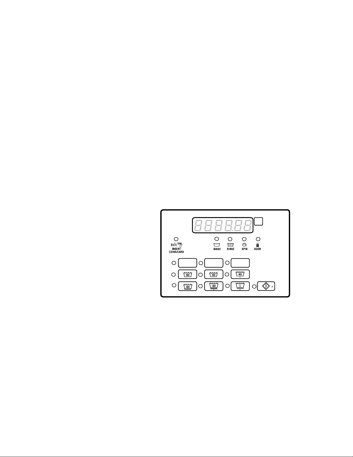
Control Identification
FLW82R_SVG
90
FLW83R_SVG
60
FLW84R_SVG
40
FLW85R_SVG
60
FLW86R_SVG
30
FLW87R_SVG
FLW102R_SVG
Control Identification
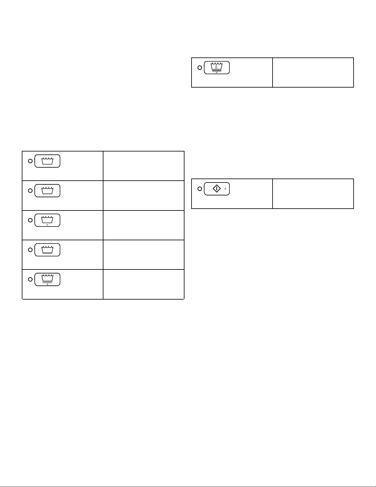
Select Cycle Pads
SELECT CYCLE pads are used to select the specific washer cycle. These pads include NORMAL 90, NORMAL 60, NORMAL
40, PERM PRESS 60, DELICATES 30 and DELICATES COLD.
These pads allow the user to select a cycle other than the default
cycle (PERM PRESS 60). The SELECT CYCLE keypads are not
active after the first fill step of the cycle. The selected cycle is indicated by the light (LED) on the pad. Pressing the flashing
START pad will confirm the selection and the cycle will begin.
When the card reader is used, pressing the START pad will start
the cycle and deduct the vend price from the card.
NORMAL 90
NORMAL 60
NORMAL 40
PERM PRESS 60
DELICATES 30
DELICATES COLD (temperature of water from tap)
NOTE: The number on each keypad corresponds to the
wash temperature in °C.
The SELECT CYCLE pads are used in various combinations for
programming cycles, retrieving audit information, running diagnostic tests, and other operations. These instructions cover the
manual programming and data retrieval options.
START Keypad
The START keypad is used to start the washer after the full vend
price has been satisfied.
START
Select Cycle Modifier Pads
The Cycle Modifier pads are used to select cycle modifier options. The A option is the default and indicates no cycle modifiers
are active. The B and C options can be programmed to offer extra
features for an added vend price. Features available include an
added prewash, extra wash time, an added extra rinse, extra rinse
time and a warm rinse temperature.
©
Published by permission of the copyright owner -
DO NOT COPY or TRANSMIT
Table continues...
12 Part No. 805405ENR5
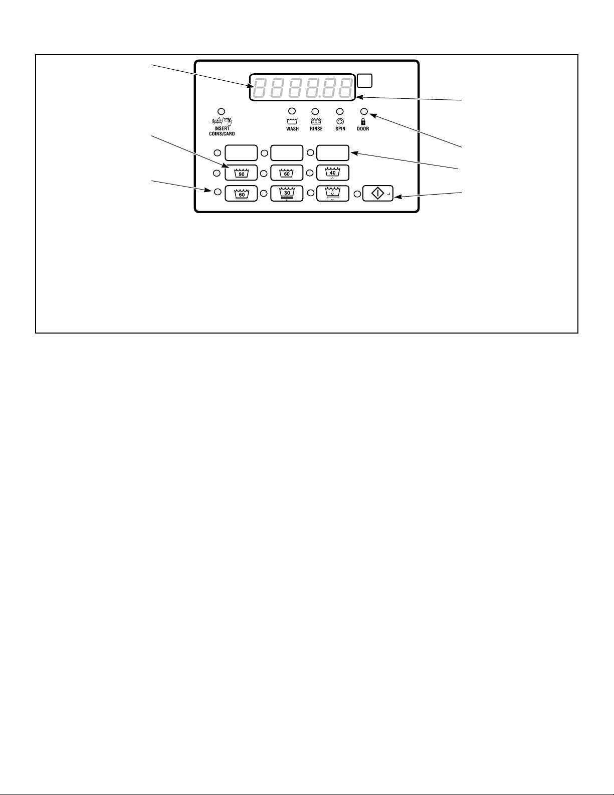
A
B C
7
5
4
3
2
1
FLW92R_SVG2
6
1. LED Light
2. SELECT CYCLE pads
3. Six 7-Segment Digits
4. Display
5. LED Status Lights
6. SELECT Cycle Modifier pads
7. START pad
Control Identification
Figure 1
©
Published by permission of the copyright owner -
DO NOT COPY or TRANSMIT
13 Part No. 805405ENR5

Display Identification
Display Identification
Light Emitting Diodes (LEDs)
LIGHT EMITTING DIODES (LEDs) are used to indicate the
chosen cycle and cycle status. See below for information on each
LED.
CYCLE LED
CYCLE LED will remain lit the entire cycle.
WASH LED
WASH LED is lit at the beginning of a wash portion of the cycle
and will remain lit until the wash is complete.
RINSE LED
RINSE LED is lit at the beginning of a rinse portion of the cycle
and will remain lit until the rinse is complete.
SPIN LED
SPIN LED is lit during the Final Spin portion of the cycle.
INSERT COINS/CARD LED
7-Segment Digits
The 7-SEGMENT DIGITS are used to display the time remaining in a cycle, vend price, error messages and descriptive codes.
During diagnostic testing or manual programming of the control,
these digits will display descriptive codes and values.
INSERT COINS/CARD LED prompts the user for coins or a card
to satisfy the vend price. The six digits show the vend price remaining to be satisfied. The vend price displayed will decrease
with each coin inserted. If new options are selected before the
first fill step of the wash cycle completes and it requires additional vend, the INSERT COINS/CARD light will flash one (1) second on and one (1) second off, and the display will flash the vend
price remaining to be satisfied one (1) second on/off.
DOOR LED
DOOR LED is lit whenever the door is locked. The door can’t be
opened when this LED is lit.
A LED
A LED is lit when the Option A modifier is selected.
B LED
B LED is lit when the Option B modifier is selected.
C LED
C LED is lit when the Option C modifier is selected.
©
Published by permission of the copyright owner -
DO NOT COPY or TRANSMIT
14 Part No. 805405ENR5

Washer Operation
Washer Operation
Power Up
When power is applied to the washer, the control will display its
control type as FL, software version as SXXX (XX is the version
number) for one (1) second each. If the control was not powered
down during a running cycle, it will enter the Ready Mode.
Ready Mode
In this mode of operation, the display shows the current selected
cycle, modifier, temperature and the full current vend price for
that cycle. The INSERT COINS/CARD LED is lit.
To start the cycle, the user must satisfy the vend price and then
press the START keypad.
The user will be able to select a different cycle/wash water temperature or modifier by pressing a cycle pad when the machine is
in the ready mode or before the first fill is complete.
Partial Vend Mode
The control enters this mode when part of the vend price has been
entered, but not enough vend is entered to satisfy the vend price.
The control will display the remaining vend price needed to start
the cycle and the INSERT COINS/CARD LED is lit.
Additional Vend Mode
The control enters this mode if a change is made before the first
fill is complete. If the vend price is not satisfied within one (1)
minute, the washer control will go back to the first selection and
the cycle will continue. Pressing the START keypad will cancel
cycle changes and exit this mode. After the first fill, all key
presses will be ignored, allowing the washer to go through the
complete cycle.
Start Mode
The control enters this mode when the full vend price is satisfied,
the vend price is zero, or the control is in OPL Mode. The
START pad LED will flash one (1) second on and one (1) second
off. If Start Mode is entered because the vend price is satisfied or
the control is in OPL Mode, the display will show PUSH for one
(1) second, StArt for one (1) second and the current cycle time
for one (1) second. If Start Mode is entered because the vend
price is zero (0), the display will show FrEE. When first entering
Start Mode, a signal will sound for one (1) second on and one (1)
second off for 10 seconds if Signal for Start is enabled.
After pressing the START keypad, the door will lock and the cycle will begin.
End of Cycle Mode
When a cycle is complete, the control will display 00 until the
washer is opened, a key is pressed, or a coin/card is entered.
When one of these three options occurs, the display will revert
back to the ready mode.
Door Locking Mode
The control enters this mode after the Start pad is pressed in Start
Mode or Pause Mode to start or resume a machine cycle. The
control will stay in Door Locking Mode until the loading door is
closed and locked. The control shows the remaining cycle time
and the Door Lock LED flashes one second on/off.
Once the door is locked, the control will exit Door Locking Mode
and will enter Run Mode. If the door is opened prior to being
locked, the control will return to Start Mode.
Door Unlocking Mode
This mode is entered when there is no time left in the cycle or
when pausing the cycle while in Run Mode. The door will unlock
after the basket stops spinning. The display will continue to flash
the remaining cycle time every second or if the next mode is End
of Cycle Mode, it will flash 01 every second. If the next mode is
Pause Mode, the display will flash PAUSE every second. If the
drive board determines that the water temperature is too hot to
drain or unlock the door, the display will flash Hot in addition to
the other displays.
The machine will always drain water down to an empty level before attempting to unlock the door. If after the programmed time
of draining, the water level is still not low enough, the control
will enter Machine Error Mode with a drain error, if enabled.
Otherwise the control will continue to drain until it sees the machine empty.
The Start key can be pressed while in this mode as long as Machine Error Mode or End of Cycle Mode is not the next mode. If
the Start key is pressed and the next mode is Pause Mode or Start
Mode, the next mode entered will be Door Locking Mode. Otherwise the press is invalid. All other keys are invalid while in this
mode. Once Door Unlocking Mode is exited, the control will enter the next mode.
Cycle Sequence
Upon the start of a cycle, the control will display the total cycle
time. The appropriate LEDs will light while the machine passes
through different cycle steps. Any coin entered after the first fill
completes will be added to the total coin counter, but the user will
not be able to change cycles.
©
Published by permission of the copyright owner -
DO NOT COPY or TRANSMIT
15 Part No. 805405ENR5

Washer Operation
Closing Washer Door
If the door is not closed when the vend price is satisfied, CLoSE
and door will be displayed until the door is closed. Once door is
closed, the START pad must be pressed to lock door and start the
cycle. If the door does not lock within 20 seconds of being
closed, E dL1 will be displayed, indicating a door lock error,
while the door continues to try to lock.
If the door locks after 20 seconds, the door lock error will clear
and the cycle will continue normally. The door can be opened to
clear the door lock error as well.
Signals
There are five options when a signal can be used during the
washer operation. These five options are listed below:
1. End of Cycle Signal By default, this signal is turned off. If
turned on, the signal sounds for three (3) seconds at the end of
a cycle.
2. Signal On Keypad Depression By default, this signal is
turned on and sounds for a quarter of a second each time a
keypad is pressed.
3. Signal On Coin Input/Card Insertion By default, this signal
is turned on and will sound for a quarter of a second each time
a coin or card is entered.
4. Signal for Serial or Network Vending Command By default, this signal is turned on for a quarter of a second when
the control receives a valid serial or network vend command.
5. Signal for Start By default, this signal is turned on and will
sound one (1) second on and one (1) second off for 10 seconds after vend price has been satisfied.
NOTE: Refer to Programming Control to program signal
options.
to Enabled and if the control is in Run Mode or Door Locking
Mode.
If this mode is entered the control will pause the cycle, enter
Door Unlocking Mode, and drain/pump the water out. After the
machine is confirmed to be empty and not rotating, the control
will unlock the door. The control will then enter Pause Mode.
The user may then restart the machine by pressing the START
pad, where the machine will enter Door Locking Mode and once
the door locks, the cycle will resume from where it left off.
NOTE: The display will show PUSH and StArt, the Cycle Selection LEDs will be lit, and if the door is locked,
the door lock LED will be lit.
Delayed Start Setup (OPL Only)
Delayed Start Setup Mode is entered by holding any key except
for the START key for 5 seconds while in Start Mode. To prevent
changing the selected cycle and options, the user should press
and hold one of the actively selected keys.
The door must be closed in order to enter this mode.
This mode is only manually accessible if the Delayed Start Mode
(Enable/Disable) parameter is programmed to Enabled. While in
the Delayed Start Setup Mode, pressing the NORMAL 40 (∧) or
the DELICATES COLD (∨) keypads will alter the number of
hours the cycle is delayed up to a maximum of 72 hours. The
time will loop around when the maximum or minimum value is
reached. The display will show XX HrS while modifying time or
01 Hr if 1 hour is set and this display will toggle 1 second on
and 1 second off.
If the door is opened while trying to program the delayed start
time, the control will exit this mode and go back to Start Mode.
Delayed Start (OPL Only)
Changing Cycles
Cycles and wash temperature can be changed before the first fill
is complete. After the first fill, all key presses are ignored.
Selecting a higher priced cycle/wash temperature or modifier will
pause the first fill step, and INSERT COINS/CARD LED will
flash one (1) second on and one (1) second off until the vend
price has been satisfied. After the vend price has been satisfied,
the cycle will continue with the new selections. If the vend price
is not satisfied within one (1) minute, the washer control will go
back to the previously set cycle/wash temperature and modifier.
Pause Mode
Pause Mode is entered when the START pad is pressed three
times within 5 seconds during the first 3 minutes of a running
machine cycle. This mode is only manually accessible if the
Pause/Resume Mode (Enable/Disable) parameter is programmed
©
Published by permission of the copyright owner -
DO NOT COPY or TRANSMIT
Delayed Start is entered by pressing the Start keypad while in
Delay Start Setup Mode. This mode is only manually accessible
if the Delayed Start Mode (Enable/Disable) parameter is programmed to Enabled. The OPL Delay Start programming parameter can be programmed through IrDA and Network commands.
The display will show XX HrS toggled with dELAy every 1 second while counting down the hours. The display will show XX
Nin toggled with dELAy every 1 second once the time is 1 hour
or less (would transition from 02 HrS to 60 Nin). The display
will count down one hour or minute at a time showing a leading
zero for one digit numbers.
Once the countdown time has expired or if the Start key is pressed while counting down delayed start time, the control will enter
Door Locking Mode to begin the cycle. Cycle selection related
LEDs will be lit while in this mode.
This mode can be exited by pressing the Back keypad which will
then place the control into Start Mode.
16 Part No. 805405ENR5

Washer Operation
If the door is opened at any point while in this mode, Delayed
Start Mode will be exited and the control will enter Start Mode.
Auto Flush Mode
The Auto-Flush Mode is only available if enabled in the Control
Configuration. The programmable Auto-Flush option allows the
control to be set to automatically flush the dispenser compartments at predetermined intervals and times. The option may be
enabled or disabled. Auto Flush is entered if the following conditions are met.
1. It must be enabled in the Progamming Parameters.
2. The machine is in Ready Mode, Start with OPL Mode Active
and not in Power Recovery, or Shut-Down Mode with the door
closed.
3. The pre-programmed number of cycles have occurred since the
last Auto-Flush.
4. The current day-of-week matches the programmed day-of-
week.
5. The current hour matches the programmed hour.
If these conditions are met, then the control will flush the dispenser compartments with hot water for a pre-programmed number of seconds (factory default is 30 seconds) or until the pressure
sensor senses water up to the door level.
Overflow Mode
If the control isn’t running a cycle, is not in Door Locking Mode
or Door Unlocking Mode, the overflow level is set at 6 inches. In
Overflow Mode, if the door is closed, the door will lock, the
pump will turn on, and the gravity drain will open until the water
level is below the overflow reset level if running a cycle, otherwise the machine will drain until the drum is seen empty.
If Overflow Mode Display is disabled and the control will enter
Run Mode when it exits, the display will show the default Run
Mode display, otherwise in all other cases, the display will show
oFLo. If the door locks and the overflow level is no longer being
met within five (5) minutes of first detecting the overflow, the cycle will continue as normal and the control will go back to the
mode it was previously in. If the control continues to see an overflow error after five (5) minutes has been reached with the door
locked, the control will enter Machine Error Mode with an Overflow Error.
Lockout Mode
control is in Ready Mode. The display will show rES. User access is ignored until Lockout Mode is exited. The control will be
able to communicate with the Network, IR, or the Serial Payment
System.
When entering the sequence of keypresses to exit Lockout Mode,
pressing the START keypad signals the end of the keypress sequence. As each keypad is pressed the corresponding LED is lit.
Anytime the START keypad is pressed the correct number of
keys entered is verified and if not equal to four (4) the keypad sequence will be reset, all LED’s will be turned off, and keypresses
will be ignored for five (5) seconds while remaining in Lockout
Mode. In addition, if five (5) keypads are pressed before the
START keypad is pressed, the sequence will be reset, all LED’s
will be turned off, and keypresses will be ignored for five (5) seconds while remaining in Lockout Mode.
When the correct sequence of keypresses has been entered the
control will enter Ready Mode. If the network programs the duration to zero, Lockout Mode will be exited.
Shutdown Mode
Shutdown Mode is entered if a Low Power/Shutdown Option (1,
2, 3, or 4) becomes active with the Shutdown option enabled. To
become active, the Low Power/Shutdown Option must be enabled in the Control Configuration and the current time, day-ofweek, date, month, and year must match the programmed start requirements for the triggering Low Power/Shutdown Option.
If the control is in ready mode, drop-off mode, lockout mode, or
start mode when no vend has been entered, shutdown mode can
be entered. Shutdown Mode will automatically exit if the current
time, day-of-week, date, month, and year satisfy an exit condition
for the active Low Power/Shutdown Option. While in Shutdown
Mode, the control will show oFF and all LEDs will be turned off.
Shutdown Mode can be exited by disabling the triggering Low
Power/Shutdown Option (1, 2, 3, or 4) through Network and IrDA commands. In addition, the Low Power/Shutdown Option (1,
2, 3, or 4) can be disabled using manual programming.
Power Failure Display Mode
In Power Failure Display Mode the control will show PrFAiL.
This informs the user that a cycle was interrupted and did not
complete normally. This mode is entered from Power-Up Mode if
a power failure occurred during an OPL cycle and the cycle is not
able to automatically resume. If the user presses any key, Start
Mode is entered.
If enabled in the Control Configuration, Lockout Mode is entered
to prevent the machine from being used except by a particular
user who has reserved the machine in advance. This mode is entered when the current time (in Hours and Minutes) falls within
the time period set by the Lockout Mode Start Time Hour, Lockout Mode Start Time Minute, Lockout Duration, and when the
©
Published by permission of the copyright owner -
DO NOT COPY or TRANSMIT
17 Part No. 805405ENR5

Special Features
Special Features
Programming Control
The control allows the owner to program the control with the use
of the keypad. Cycle and vend information may be programmed,
audit information may be viewed and diagnostic tests may be run
by pressing keypad combinations.
Collecting Audit Information
The control stores audit information in its memory that can be retrieved by pressing various combinations of Select Cycle pads.
For more information on the audit features, refer to Collecting
Audit Information.
NOTE: Additional audit information is retrievable with
an external device, the card reader and the network.
Refer to the appropriate instruction manual.
Testing Machine and Control Functions
Special diagnostic features built into the control allow the owner
to run specific diagnostic tests. By opening and closing the service door and then pressing various sequences of Select Cycle
pads, the owner may perform the following tests:
• Machine Configuration #5 Display Test
* Tests can only be entered when in Start or Ready Mode.
For detailed information on running diagnostic tests, refer to Test-
ing Machine and Electronic Control Functions.
Rapid Advance Feature
This feature allows the user to quickly advance through an active
cycle or advance into a cycle from the Ready Mode. This feature
is useful when tests must be performed immediately on a machine currently in an active cycle. In this case, the user can quickly advance through the cycle to the Ready Mode. At this point,
the user can perform the required tests and then return the machine to the active cycle.
Clearing the Vend Feature
This feature allows the user to return the control back to the
Ready Mode if coins have been entered but the full vend price
has not yet been satisfied, while in Partial Vend Mode.
For more information on using the Clear Vend feature, refer to
Clear Vend Feature.
• Control Software Version # Test
• Drive Board #1 Software Version Test
• Water Level Trim Test
• Service Door Switch Input Test
• Coin Vault Switch Input Test
• Coin Drop #1 Input Test
• Coin Drop #2 Input Test
• Vend Connection Header Present Input Test
• Start Pulse Input Test
• Door Switch Input Test*
• Door Lock Switch Input Test*
• Show Fill Time Test
• Show Drain Time Test
• Temperature Sensor Display Test (Heater/Temp Sensor only)
• Out of Balance Switch Input Test
• External Output Test*
• Water Purge Test*
• Water Leak Detection Test*
• Water Level Test
• DC Bus Voltage Test
• AC Mains Voltage Test
• Machine Configuration #1 Display Test
• Machine Configuration #2 Display Test
• Machine Configuration #3 Display Test
• Machine Configuration #4 Display Test
Communications Mode
This feature allows the machine control to communicate with an
external device, the card reader, or the network. This allows the
washer control to be programmed and have its data read without
using the keypad.
For more detailed information on using the Communications
Mode feature, refer to Communications.
Coin Drop
The control will accept pulses from a single or dual coin drop to
satisfy vend price. Each coin drop will have the ability to satisfy
the vend.
Start Pulse Operation
The control will accept pulses from optional payment systems.
The machine can be programmed to receive a single start pulse or
multiple start pulses, or the Start Pulse Option can be turned off.
The Start Pulse Mode allows the machine to go from the Ready
Mode to the Start Mode after a single or multiple pulses are received.
©
Published by permission of the copyright owner -
DO NOT COPY or TRANSMIT
18 Part No. 805405ENR5

Special Features
Service Door and Coin Vault Openings
The control will capture the times and dates of the last seven
openings of the Coin Vault and the Service Door. The information is saved in memory. An open service door and a closed coin
vault combined with various keypad presses allows the control to
enter manual modes of operation if the Break-In Alarm is not on.
These modes include Manual Programming, Audit Collection,
Diagnostics, Rapid Advance, and Reset to Factory Defaults.
Break-In Alarm
This feature allows the owner to program the machine to signal a
network alarm, cause a machine alarm or shut down the machine
if the service door or coin vault is opened without disabling the
alarm first. The date and time of the break-in is recorded. To
avoid the alarm during coin collections, the alarm must be turned
off or temporarily disabled by pressing the two programmed
keys.
The alarm is turned off by default. The alarm can be turned on by
programming the control with an external device or network.
Special Vend
This feature allows the owner to program the control to allow
programmable vend prices for specific hours and dates.
For details on programming Special Vend, refer to Programming
Control.
OPL Mode
This feature allows the user to start a cycle without satisfying the
vend price.
For details on enabling OPL Mode, refer to Programming Con-
trol.
For details on programming the Low Power/Auto-Shutdown option, refer to Programming Control.
Temperature Display
This feature allows the owner to view the water temperature on
the display of a machine with a heater by pressing any cycle keypad during an agitate or soak step of the cycle.
The temperature display is turned off by default. The feature can
be turned on by programming the control with an external device/
network or manually.
Out of Order Mode
This feature allows the owner to program Out of Order Mode
which can be used to show the user that the machine is not available to use. The control will accept coins and increment the appropriate audit counters but the vend entered will not count towards a cycle purchase, the coin audio will not work, and no cycle will run while Out of Order Mode is active.
Network Node Number Display Mode
This feature allows the owner to program a command to be sent
from the IrDA or Network that requests the front-end control to
display the network node number. The Control will display nXXX
where XXX is the network node number.
Error Display Mode
This feature is used to display a machine error. Only one error
will be displayed at the time if there are multiple errors. Once the
highest priority error is cleared, the next highest priority error
will be displayed if multiple errors exist. Refer to Error Codes
for more details on errors, their displays, and their priorities.
Drop-Off Mode
This feature allows the owner to limit machine use to an attendant without requiring vend. Starting the machine will require the
correct sequence of four keypad presses followed by the START
key as programmed by an external device. These keys can be programmed by an external device and are defaulted as modifier A,
modifier B, modifier C and NORMAL 90.
For details on enabling Drop-Off Mode, refer to Programming
Control.
Low Power/Auto-Shutdown Option
This feature allows the owner to program the control to shut
down or enter a low power consumption mode based on programmable times and dates if either of these options are enabled.
©
Published by permission of the copyright owner -
DO NOT COPY or TRANSMIT
19 Part No. 805405ENR5

Opening the Service Door
Stacked Washers and Dryers, 10 De-
gree Front Control Washers and Coin
Rear Control Washers
Manual programming requires the user to open and close the
service door. Opening and closing the service door trips a switch
allowing access to various programming options, diagnostics, and
audit capabilities. On coin models, the coin vault switch must be
closed to enter Manual Mode.
The service door is located in the control panel on the Stacked
Washer and Dryers and Front Control Washers. On Rear Control
Washers, the service door is located on the top of the meter case.
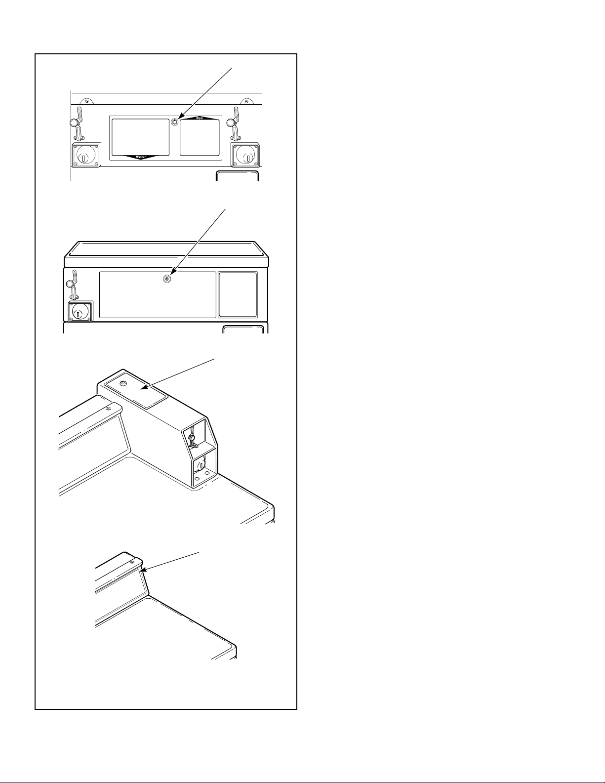
Refer to Figure 2 .
After opening and closing the service door, the programmer has
4.25 minutes to begin programming. If a keypad has not been
pressed in that time, the control will revert back to the Ready
Mode. Refer to Figure 2 .
Opening the Service Door
NOTE: If the Break-In Alarm option is enabled, it must
be turned off or disabled by pressing the two programmed keys before opening service door. For more information on using the Break-In Alarm, refer to the external device or network software instructions.
Rear Control Washers with Card Reader
Manual programming requires the user to remove the control
panel and unplug the bullet connector located between the
“white/black” and “red/blue” wires. This will allow the user to
access various programming options, diagnostics, and audit capabilities. Refer to Figure 2 .
©
Published by permission of the copyright owner -
DO NOT COPY or TRANSMIT
20 Part No. 805405ENR5
1
FLW31R_SVG
FLW32R_SVG
1
W521I_SVG
1
FLW6R_SVG1
2
Opening the Service Door
OPL Models
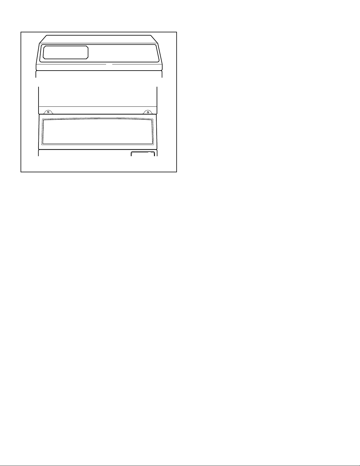
Preparing for Manual Mode
Manual programming requires the user to remove the cabinet top
or control panel and unplug the bullet connector located between
the “white/black” and “red/blue” wires. This will allow the user
to access various programming options, diagnostics, and audit capabilities. Refer to Figure 3 .
Single Units
1. Remove the screws from the back of the top panel that attach
the top panel to the machine.
2. From the back of the machine, using a screwdriver, pry the
top panel upward and towards you.
3. Remove the screws from the top of the control panel that attach the control panel to the machine.
4. Remove the screws from the bottom of the control panel that
attach the control panel to the machine.
NOTE: When reinstalling the control panel, be sure to
align the control panel’s tabs with the machine’s tabs.
Stack Units
1. Remove the screws from the bottom of the dryer front panel.
2. Remove the screws that attach the bottom of the dryer base to
the frontload washer’s control panel.
3. To gain access to the control panel’s components, tilt the dryer back slightly and insert a 27-inch 2 x 2 between the dryer
and washer.
4. As an alternative, remove the control panel using putty knives.
a. Insert a thin putty knife between the frontload washer’s
control panel and front panel to disengage the control panel’s tabs.
b. The control panel’s tabs are located 8.71 inches from the
edge of the left and right side panels.
1. Service Door
2. Control Panel
Figure 2
©
Published by permission of the copyright owner -
DO NOT COPY or TRANSMIT
21 Part No. 805405ENR5
FLW2384N_SVG
SWD990N_SVG
Opening the Service Door
Figure 3
©
Published by permission of the copyright owner -
DO NOT COPY or TRANSMIT
22 Part No. 805405ENR5

Entering the Manual Mode
Entering the Manual Mode
How to Enter the Manual Mode
For programming, testing, and retrieving information from the
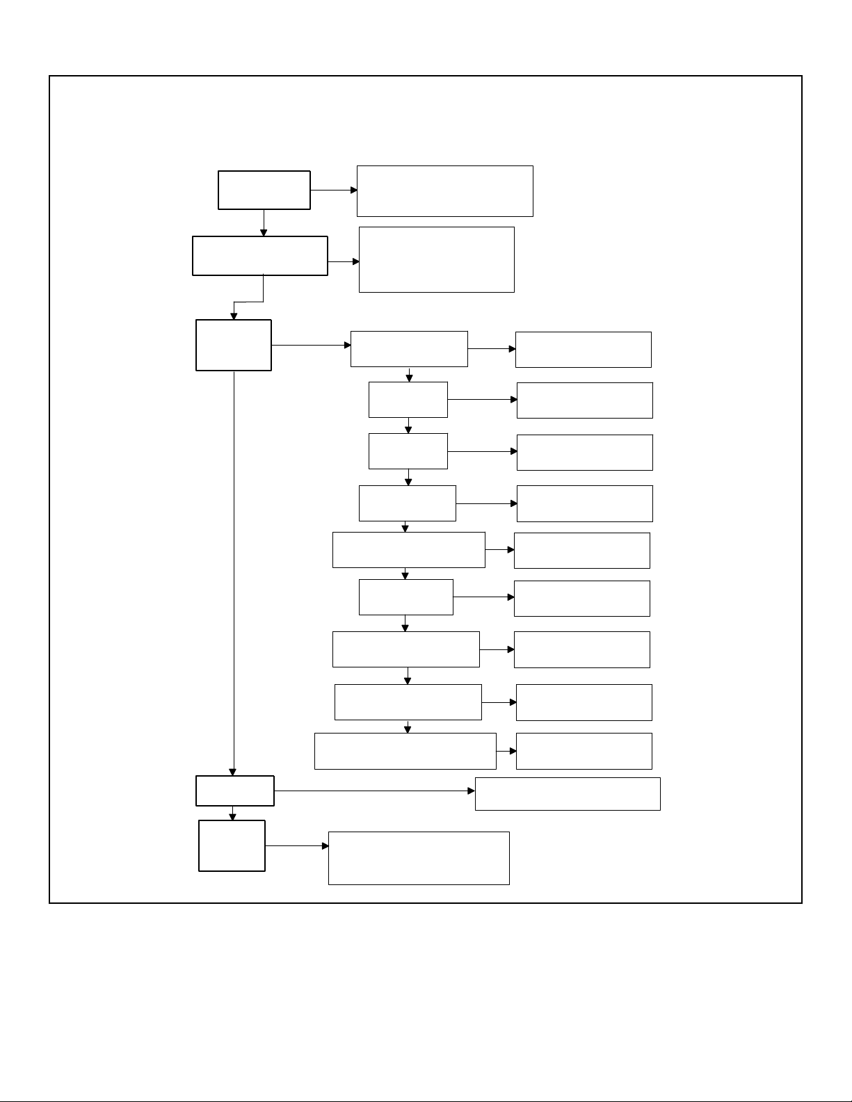
control, it is often necessary to enter the Manual Mode by following the four simple steps below. For an overview of entering the
Manual Mode, refer to the flowchart on the following page.
1. If accessing Diagnostic Tests that take control of machine operation, be sure the washer is in the Start or Ready Mode before continuing to step 2. If the washer is in an active cycle,
rapid advance through the cycle. Refer to Rapid Advance
Feature.
2. Open the service door.
NOTE: The coin vault switch must be closed to enter Manual Mode.
3. While pressing and holding the A keypad with one hand,
press the NORMAL 90 keypad with the other hand.
4.
The display will show rAPid .
5. Press the NORMAL 40 (∧) or the DELICATES COLD (∨)
keypad to scroll through the options until the desired option
appears in the display.
6. Press the START (enter) keypad.
NOTE: After entering Manual Mode, if no keypads
are pressed for 4.25 minutes, the control will return
to the previous mode of operation.
7. To exit, press the DELICATES 30 ( < ) keypad. The control
will revert back to Ready Mode.
Manual Mode Navigation
Manual Mode is broken into five groups: Manual Programming,
Manual Read Audit, Manual Reset, Manual Rapid Advance and
Manual Diagnostics. Manual Programming can only be turned on
or off with an external device or the network. Refer to the appropriate instruction manual. Manual Rapid Advance and Manual
Diagnostics can be turned on and off using an external device, by
manual programming, or with the network.
By default, all groups are turned on.
The manual features available in each group are as follows (the
menu shown on the display in this mode is in parentheses).
•
Manual Programming (Prog)
•
Manual Read Audit (AUdit)
•
Manual Reset (rESEt)
•
Rapid Advance (rAPid)
•
Manual Diagnostic Tests (diAg)
If a group is turned off, the display will change from the selected
feature to oFF when the START (enter) pad is pressed. An audio
signal will then sound for one (1) second and the display will return to the selected feature. The features in the group cannot be
entered.
©
Published by permission of the copyright owner -
DO NOT COPY or TRANSMIT
23 Part No. 805405ENR5
FLW103R_SVG
"rAPid"
Rapid Advance
"Prog"
Manual Programming
"AUdit"
Manual Read
Audit
"rESEt"
Manual Reset
"diAg"
Diagnostic
Tests
Press the START keypad to
begin Rapid Advance cycle and
to advance through cycle steps.
Press the START keypad to
enter Manual Programming.
Refer to Manual
Programming flowchart.
"CyCLES"
Total machine cycles
"Coin 1"
Total coins #1
"PULSE"
Total start pulses
"Coin 2"
Total coins #2
Press the START keypad to enter
Manual Reset Mode.
Press the START keypad to
enter Diagnostic Tests. Refer to
Diagnostic Tests flowchart.
Press the START (enter)
keypad to read audit.
Press the START (enter)
keypad to read audit.
Press the START (enter)
keypad to read audit.
Press the START (enter)
keypad to read audit.
"rAPCyC"
Total Rapid Advance Cycles
"rCoin1"
Resettable Coin #1 count
"rUnHrs"
Total run hours
Press the START (enter)
keypad to read audit.
Press the START (enter)
keypad to read audit.
Press the START (enter)
keypad to read audit.
"rCoin2"
Resettable Coin #2 count
Press the START (enter)
keypad to read audit.
"rCyCLE"
Resettable Machine Cycle count
Press the START (enter)
keypad to read audit.
Entering the Manual Mode
• Manual Mode: Enter by opening the service door for at least 1 second and then closing service door. Then press A and NORMAL 90 keypads at the same time.
• Press the NORMAL 40 or DELICATES COLD keypad to scroll through the Manual Mode options.
• Press the START keypad to enter any sub-menu options.
©
Published by permission of the copyright owner -
DO NOT COPY or TRANSMIT
Figure 4
24 Part No. 805405ENR5

Programming Control
Programming Control
What Can Be Programmed
This feature allows the owner to program cycle information,
standard vend pricing, special vends and other features by using
the keypads. The control must have the Manual Programming
Mode enabled, which is the factory default.
This mode can only be turned “OFF” and “ON” by using an external device or the network.
Refer to this section when programming the control. This section
offers a detailed description of all options available to program.
Each description includes instructions on when and why the option might be used and, more importantly, how to program the
option.
Option Number Option Display Description Factory Default Value Range
1
2
3
4
AtS 1
AtS 2
AtS 3
AtS 4
Vend Price #1 200 0 - 65,535
Vend Price #2 200 0 - 65,535
Vend Price #3 200 0 - 65,535
Vend Price #4 200 0 - 65,535
For an overview of the programming organization, refer to the
flowcharts on the following pages.
For more advanced users, a quick reference list of the options
available through the programming mode is located on this page.
NOTE: The letters and numbers in the Option Display
column of the Programmable Options List are what will
be shown in the display when that option is selected.
Programmable Options Available
5
6
7
8
9
10
11
12
13
14
15
AtS 5
AtS 6
ACMP 1
ACMP 2
Ats dP
dEn 1
dEn 2
PLSE
PLSNod
AtyPE
dFtCyC
Vend Price #5 200 0 - 65,535
Vend Price #6 200 0 - 65,535
Cycle Modifier Key 1
B Vend Price Adder
Cycle Modifier Key 2
C Vend Price Adder
Vend Price Decimal
Point
Coin #1 Value 25 1 - 65,535
Coin #2 Value 100 1 - 65,535
Start Pulse Value 25 1 - 65,535
Start Pulse Mode 128 0, 128, 192
Programmable Output
Type
Default Cycle 3 1 - 6
25 0 - 65,535
50 0 - 65,535
2 oFF, 2, 3
0 0 - 13
Table continues...
©
Published by permission of the copyright owner -
DO NOT COPY or TRANSMIT
25 Part No. 805405ENR5
Programming Control
Option Number Option Display Description Factory Default Value Range
16
17
18
19
a
1
2
3
b
1
2
c
CArd
AUdio
nodE
Error-
CErr-
CErr 1
CErr 2
CErr 3
E FL-
E FL 1
E FL 2
E nF-
Card Reader Display
oFF on/oFF
Control
Audio Signal 29 0 - 31
Network Node Number 250 1 - 250
Errors Menu — —
Coin Error Parameters
— —
Menu
Coin Error on on/oFF
Coin Error Penalty oFF on/oFF
Vend Header Present
on on/oFF
Error
Fill Error Menu — —
Fill Error on on/oFF
Fill Error Time 30 2 - 59
No Water Flow Error
— —
Menu
1
2
E nF 1
E nF 2
No Water Flow Error on on/oFF
No Water Flow Error
5 1 - 59
Time
d
E Hd
Too Hot to Drain Error
oFF on/oFF
(Heater/Temp Sensor
only)
e
1
2
E dr-
E dr 1
E dr 2
Drain Error Menu — —
Drain Error on on/oFF
Drain Error Time 15 = Through Serial
1 - 59
No. 1507032556
5 = Starting Serial No.
1507032557
f
E Ld-
Water Leak Detection
— —
Error Menu
1
E Ld 1
Water Leak Detection
oFF oFF, 3 - 255
Day of Week
2
E Ld 2
Water Leak Detection
10 0 - 127
Number of Cycles
©
Published by permission of the copyright owner -
DO NOT COPY or TRANSMIT
Table continues...
26 Part No. 805405ENR5

Programming Control
Option Number Option Display Description Factory Default Value Range
3
E Ld 3
Water Leak Detection
on on/oFF
Display Sequence
g
E Sd-
Slow Drain Detection
— —
Error Menu
1
2
E Sd 1
E Sd 2
Slow Drain Detection oFF on/oFF
Slow Drain Detection
0 0 - 255
Adjust
h
E oP
Open Thermistor Error
on on/oFF
Display (Heater/Temp
Sensor only)
i
E SH
Shorted Thermistor Er-
on on/oFF
ror Display (Heater/
Temp Sensor only)
j
E StHt
Slow to Heat Error
oFF oFF, 1-255
(Heater/Temp Sensor
only)
k
E Ht-
Heater Error Menu
— —
(Heater/Temp Sensor
only)
1
2
l
E Ht 1
E Ht 2
E tE
Heater Error on on/oFF
Heater Error Time 120 1-255
Water Temperature Ex-
on on/oFF
ceeded (Heater/Temp
Sensor only)
m
E Ub
Non-Fatal Unbalance
oFF on/oFF
Error Display
n
E SL
Suds Lock Error Dis-
oFF on/oFF
play
o
SUd-
Suds Removal Routine
— —
Menu
1
SUd 1
Suds Removal Routine
oFF on/oFF
Display
2
SUd 2
Suds Removal Rou-
1 0 - 10
tines Allowed Per Cycle
3
SUd 3
Suds Removal Routine
on on/oFF
Extra Time
©
Published by permission of the copyright owner -
DO NOT COPY or TRANSMIT
Table continues...
27 Part No. 805405ENR5

Programming Control
Option Number Option Display Description Factory Default Value Range
p
q
20
21
22
23
24
25
ovrFLd
CLrErr
tP F C
FL Hot
FL HC
FL CLd
CooLdn
FL Lo
Overflow Mode Dis-
on on/oFF
play
Allow Error Clearing oFF on/oFF
Temperature (F/C)
FAHrEn FAHrEn/CELCiU
(Heater/Temp Sensor
only)
Hot Water Temperature
140F/60C 35F-194F/2C-90C
(Heater/Temp Sensor
only)
Warm Water Tempera-
104F/40C 35F-194F/2C-90C
ture (Heater/Temp Sensor only)
Cold Water Tempera-
35F/2C 35F-194F/2C-90C
ture (Heater/Temp Sensor only)
Cool Down Tempera-
140F/60C 50F-160F/10C-71C
ture (Heater/Temp Sensor only)
Low Water Level 6 1 - 30
26
27
28
29
30
a
b
c
d
e
FL NEd
FL Hi
FLSH t
norF t
rtC-
rtC 1
rtC 2
rtC 3
rtC 4
rtC 5
Medium Water Level 10 1 - 30
High Water Level 15 1 - 30
Flush Out Time for Fill
25 0 - 255
Steps
No Refill After Time
255 0 - 255
for Agitate Steps
Real Time Clock Menu — —
Set Real Time Clock
— 0 - 59
Minutes
Set Real Time Clock
— 0 - 23
Hours
Set Real Time Clock
— 1 - 7
Day of Week
Set Real Time Clock
— 1 - 31
Date of Month
Set Real Time Clock
— 1 - 12
Month
©
Published by permission of the copyright owner -
DO NOT COPY or TRANSMIT
Table continues...
28 Part No. 805405ENR5
Programming Control
Option Number Option Display Description Factory Default Value Range
f
31
a
b
c
d
e
f
g
h
i
32
rtC 6
dLS-
dLS 1
dLS 2
dLS 3
dLS 4
dLS 5
dLS 6
dLS 7
dLS 8
dLS 9
SP1-
Set Real Time Clock
— 0 - 99
Year
Daylight Savings Op-
— —
tion Menu
Daylight Saving on on/oFF
Start Month — 1 - 12
Start Day of Week — 1 - 7
Start Week of Month — 1 - 4
Start Hour — 0 - 23
End Month — 1 - 12
End Day of Week — 1 - 7
End Week of Month — 1 - 4
End Hour — 0 - 23
Special Vend 1 Param-
— —
eters Menu
a
SP1 1
Special Vend 1 Days of
oFF Refer to Table 8
Week Enable
b
SP1 2
Special Vend 1 Start
0 0 - 59
Minute
c
SP1 3
Special Vend 1 Start
0 0 - 23
Hour
d
SP1 4
Special Vend 1 Start
oFF oFF, 1 - 31
Date
e
SP1 5
Special Vend 1 Start
oFF oFF, 1 - 12
Month
f
SP1 6
Special Vend 1 Start
0 0 - 99
Year
g
SP1 7
Special Vend 1 Length
0 0 - 24
in Hours
h
SP1 8
Special Vend 1 End
oFF oFF, 1 - 31
Date
i
SP1 9
Special Vend 1 End
oFF oFF, 1 - 12
Month
©
Published by permission of the copyright owner -
DO NOT COPY or TRANSMIT
Table continues...
29 Part No. 805405ENR5

Programming Control
Option Number Option Display Description Factory Default Value Range
j
SP1 10
Special Vend 1 End
0 0 - 99
Year
k
SP1 11
Special Vend 1 Price
0 0 - 65,535
#1
l
SP1 12
Special Vend 1 Price
0 0 - 65,535
#2
m
SP1 13
Special Vend 1 Price
0 0 - 65,535
#3
n
SP1 14
Special Vend 1 Price
0 0 - 65,535
#4
o
SP1 15
Special Vend 1 Price
0 0 - 65,535
#5
p
SP1 16
Special Vend 1 Price
0 0 - 65,535
#6
q
SP1 20
Special Vend 1 Wash
0 0 - 10
Status Agitate Steps
Added Minutes
r
SP1 21
Special Vend 1 Wash
0 0 - 10
Status Agitate Steps
Subtracted Minutes
s
SP1 22
Special Vend 1 Cycle
0 0 - 2
Modifier Default Value
t
SP1 23
Special Vend 1 Cycle
0 0 - 65,535
Modifier Key #1 B
Vend Price
u
SP1 24
Special Vend 1 Cycle
0 0 - 65,535
Modifier Key #2 C
Vend Price
v
SP1 25
Special Vend 1 Cycle
0 0 - 31
Modifier Key #1 B Options
w
SP1 26
Special Vend 1 Cycle
0 0 - 31
Modifier Key #2 C Options
x
SP1 27
Special Vend 1 Extract
Speed Limit
ULtra HigH
Very Low, Low, Medium, High, Very High,
Ultra High, (37.40 -
439.70 G Force; 350 1200 RPM)
Table continues...
©
Published by permission of the copyright owner -
DO NOT COPY or TRANSMIT
30 Part No. 805405ENR5
 Loading...