

ALLIANCE DWN432SP113CW01, AWNE92SP113FW01, AWNE82SP113FW01, AWNE92SN303AW01, FWNE52SP303ZW01 Troubleshooting Manual
...
Home
Topload
Washers
Refer to page 5 for Model Numbers
Troubleshooting
www.alliancelaundry.com
TLW23C
Part No. 203562
August 2015


Table of
Contents
Section 1 – Safety Information ...............................................................3
Section 2 – Introduction ..........................................................................5
Model Identification ..............................................................................5
How Your Washer Works .....................................................................6
Customer Service...................................................................................8
Nameplate Location...............................................................................8
Section 3 – Troubleshooting....................................................................9
1. Production Test Summary.............................................................9
2. Keypad Combinations.................................................................10
3. Rapid Advance............................................................................11
4. Control Version Display .............................................................11
5. Low Water Level on High Fill Setting........................................11
6. No Hot Water - “Er”, “FL” .........................................................12
7. No Cold Water - “Er”, “FL” .......................................................14
8. No Warm Water - “Er”, “FL”.....................................................16
9. Slow Hot Fill or Warm Fill is Too Cold .....................................17
10. Water Fill Does Not Stop At Proper Level,
Fill Error “Er”, “FL”, Overflow Error “Er”, “OF” ....................18
11. “Er”, “PS” on the display, Pressure sensor error ........................19
12. Washer Fills, Motor Hums..........................................................21
13. Cycle Does Not Advance............................................................22
14. Motor Does Not Run - “tP”.........................................................23
15. No Agitation................................................................................25
16. Constant Agitation ......................................................................26
17. Washer Overheats, Cycles On Motor Thermal Protector,
Switch Actuator Kicks In And Out, “tP” ...................................27
18. Slow Spin Or No Spin.................................................................28
19. Constant Spin ..............................................................................30
20. Washer Stops In Cycle; Quits After A Couple Loads; Is
Intermittent - “tP”........................................................................31
21. Washer Is Locked Up Or Binding...............................................33
22. Outer Tub Does Not Empty “Er”, “dr” Drain Error,
“Er”, “Sd” Slow Drain ................................................................34
23. Excessive Vibration ....................................................................35
24. Water Leaking From Outer Tub..................................................36
© Copyright 2015, Alliance Laundry Systems LLC
All rights reserved. No part of the contents of this book may be reproduced or transmitted in any form or by any means without
the expressed written consent of the publisher.
203562 1
© Copyright, Alliance Laundry Systems LLC – DO NOT COPY or TRANSMIT
Section 4 – Error Codes ........................................................................37
25. Error Codes .................................................................................37
Section 5 – Adjustments ........................................................................39
26. Leveling Legs..............................................................................39
27. Belt (Agitate And Spin) ..............................................................39
Section 6 – Test Procedures ..................................................................40
28. Motor Test Procedure..................................................................40
29. Mixing Valve Solenoid Test Procedure......................................41

Section 7 – Cycle Sequence Charts
– Models AWNE82SN303AW01 and AWNE92SN303AW01............42
30. Normal ECO Cycle .....................................................................42
31. Delicate Cycle .............................................................................44
32. All Other Cycles..........................................................................45
Section 8 – Cycle Sequence Charts
– Models LWNE52SP543RW01, LWNE52WP543RW01 and
YWNE52SP543RW01 ...........................................................................46
33. Normal ECO Cycle .....................................................................46
34. Delicate Cycle .............................................................................47
35. All Other Cycles..........................................................................48
Section 9 – Cycle Sequence Charts
– Model LWNA52SP113TW01.............................................................49
36. Normal ECO Cycle .....................................................................49
37. Delicate Cycle .............................................................................50
38. All Other Cycles..........................................................................51
Section 10 – Cycle Sequence Charts – All Other Models...................52
39. Normal ECO Cycle .....................................................................52
40. Delicate Cycle .............................................................................53
41. All Other Cycles..........................................................................54
Section 11 – Internal Wiring of Washer Motor Switch......................55
Motor Assembly (1 Speed Motors).................................................. 55
Motor Assembly (2 Speed Motors).................................................. 56
2 203562
© Copyright, Alliance Laundry Systems LLC – DO NOT COPY or TRANSMIT
Section 1
• Failure to install, maintain and/or operate this product according to the manufacturer’s
instructions may result in conditions which can produce serious injury, death and/or
property damage.
• Do not repair or replace any part of the product or attempt any servicing unless specifically
recommended or published in this Service Manual and unless you understand and have the
skills to carry out the servicing.
• Whenever ground wires are removed during servicing, these ground wires must be
reconnected to ensure that the product is properly grounded and to reduce the risk of fire,
electric shock, serious injury or death.
W006R2
WARNING
Safety Information
Throughout this manual and on machine decals, you will find precautionary statements (“CAUTION,”
“WARNING,” and “DANGER”) followed by specific instructions. These precautions are intended for the personal
safety of the operator, user, servicer and those maintaining the machine.
DANGER
Danger indicates an imminently hazardous situation that, if not avoided, will cause severe personal injury or death.
WARNING
Warning indicates a hazardous situation that, if not avoided, could cause severe personal injury or death.
CAUTION
Caution indicates a hazardous situation that, if not avoided, may cause minor or moderate personal injury or property
damage.
Additional precautionary statements (“IMPORTANT” and “NOTE”) are followed by specific instructions.
IMPORTANT
The word “IMPORTANT” is used to inform the reader of specific procedures where minor machine damage will
occur if the procedure is not followed.
NOTE
The word “NOTE” is used to communicate installation, operation, maintenance or servicing information that is
important but not hazard related.
In the interest of safety, some general precautions relating to the operation of this machine follow.
203562
© Copyright, Alliance Laundry Systems LLC – DO NOT COPY or TRANSMIT
3
Safety Information
To reduce the risk of electric shock, fire, explosion, serious injury or death:
• Disconnect electric power to the washer before servicing.
• Never start the washer with any guards/panels removed.
• Whenever ground wires are removed during servicing, these ground wires must be
reconnected to ensure that the washer is properly grounded.
W003
WARNING
Repairs that are made to your products by unqualified persons can result in hazards due to
improper assembly or adjustments subjecting you, or the inexperienced person making such
repairs, to the risk of serious injury, electrical shock, or death.
W007
WARNING
If you or an unqualified person perform service on your product, you must assume the
responsibility for any personal injury or property damage which may result. The manufacturer
will not be responsible for any injury or property damage arising from improper service and/or
service procedures.
W008
WARNING
NOTE: The WARNINGS and IMPORTANT INSTRUCTIONS appearing in this manual are not meant to
cover all possible conditions and situations that may occur. Common sense, caution and care must be
exercised when installing, maintaining or operating the washer.
Always contact your dealer, distributor, service agent or the manufacturer about any problems or conditions you do
not understand.
Locating an Authorized Servicer
Alliance Laundry Systems is not responsible for personal injury or property damage resulting from improper
service. Review all service information before beginning repairs.
Warranty service must be performed by an authorized technician, using authorized factory parts. If service is
required after the warranty expires, Alliance Laundry Systems also recommends contacting an authorized
technician and using authorized factory parts.
4 203562
© Copyright, Alliance Laundry Systems LLC – DO NOT COPY or TRANSMIT

Section 2
Introduction
Model Identification
Information in this manual is applicable to these washer models.
AWNE82SP113FW01
AWNE82SN303AW01
AWNE92SP113FW01
AWNE92SN303AW01
DWN432SP113CW01
FWNE52SP303ZW01
FWNE52SP303ZW14
LWN432SP113TW01
LWNA52SP113TW01
LWNE52PP113TW01
LWNE52PP113ZW01
LWNE52PP303SW01
LWNE52SP103ZW01
LWNE52SP113FQ01
LWNE52SP113FW01
LWNE52SP113TW01
LWNE52SP113ZW01
LWNE52SP303AW01
LWNE52SP303BW01
LWNE52SP303EW01
LWNE52SP303NW26
LWNE52SP303SW01
LWNE52SP303UW01
LWNE52SP303ZW01
LWNE52SP543RW01
LWNE52SP543ZW01
LWNE52WP113FW01
LWNE52WP113TW01
LWNE52WP303ZW01
LWNE52WP543RW01
LWNE52WP543ZW01
YWNE52PP113CW01
YWNE52SP303EW01
YWNE52SP303UW01
YWNE52SP543RW01
YWNE52SP543ZW01
ZWN432SP113CW01
ZWNE82SP113CW01
ZWNE82SP113FW01
ZWNE92SP113FW01
203562 5
© Copyright, Alliance Laundry Systems LLC – DO NOT COPY or TRANSMIT
Introduction
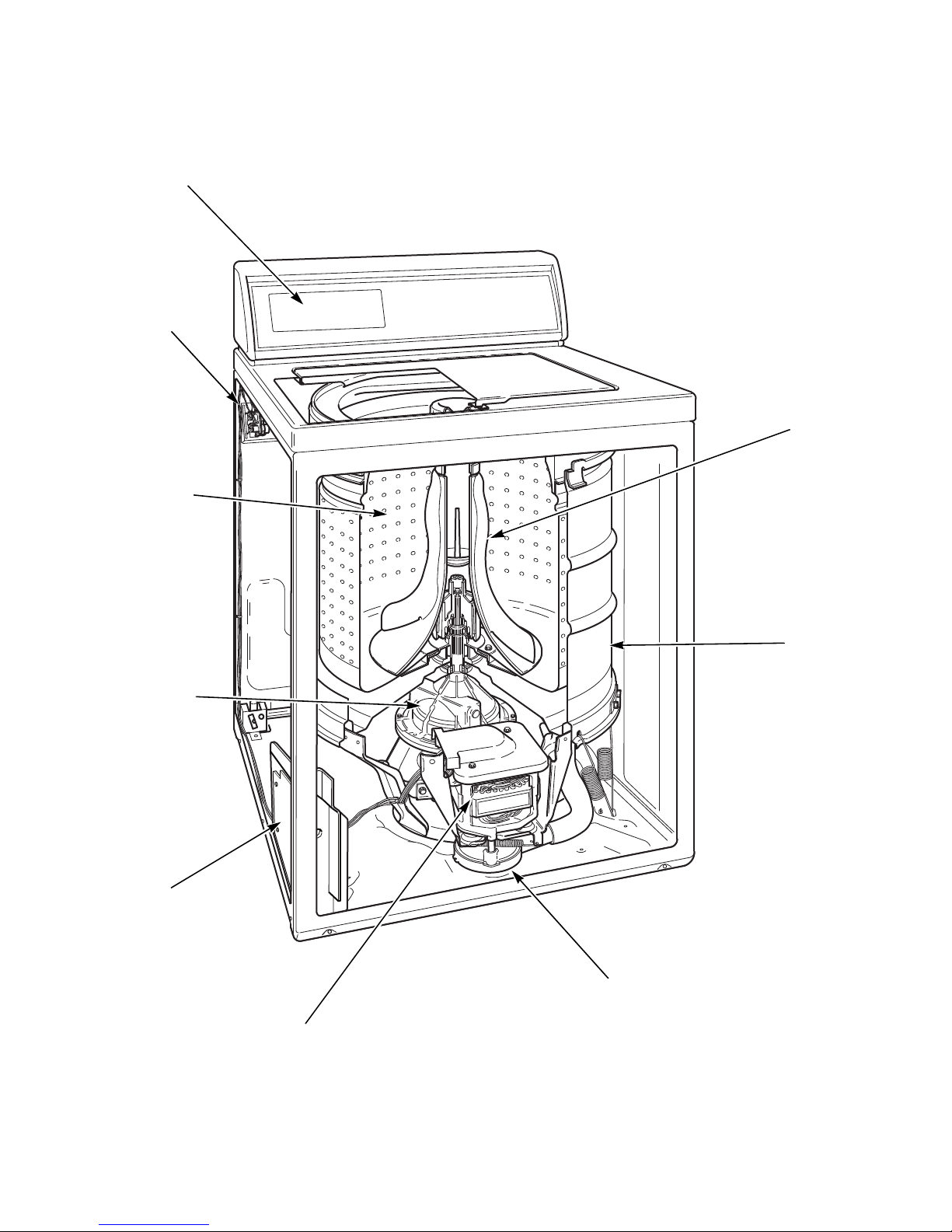
TLW422S
Electronic Control
Agitator
Outer
Tub
Mixing
Valve
Washtub
Transmission
Motor
Pump
Output
Board
How Your Washer Works
6 203562
© Copyright, Alliance Laundry Systems LLC – DO NOT COPY or TRANSMIT

Introduction
The cycle begins with a wash fill. The water
temperature is determined by the temperature selected
on the control. While water fills the washtub, a column
of air is trapped in a pressure bulb and hose. The air
pressure continues to increase as the washtub fills with
water until it is great enough to trip the pressure sensor
at the selected water level (load size). The pressure
sensor trip then causes the wash fill to stop and wash
agitation to begin. However, the lid must be closed for
any washer operation to occur.
The washer uses a reversing type motor, a special drive
belt and an idler assembly. The idler assembly applies
tension to the outside of the drive belt.
During agitation, the motor runs in the
counterclockwise direction. The spring tension on the
idler pulley applies the tension required to reduce the
slack on the drive belt and maintain maximum belt to
motor pulley contact. This eliminates belt slippage and
ensures an efficient wash action, even with extra large
loads.
The belt drives the transmission drive pulley in the
counterclockwise direction. The pulley drives the helix
which is splined to the input shaft of the transmission.
This causes the input shaft to turn inside of a roller
clutch which is pressed into the transmission cover.
This roller clutch acts as a bearing in the
counterclockwise direction allowing the transmission
gears to operate. The transmission’s rack and pinion
gear design produces a 210 degree agitation stroke at
the output shaft of the transmission which drives the
agitator. The brake assembly remains locked during the
agitation mode since no pressure is applied to it by the
transmission drive pulley.
As water is removed by the pump and the momentum
of the washtub increases, the idler spring tension
gradually overcomes the belt tension removing the belt
slack. This eventually increases the belt to pulley
contact until maximum spin speed is achieved.
The drive pulley turns clockwise riding up the ramps of
the helix, exerting pressure on the brake and forcing it
to release from brake pads. The helix drives the input
shaft of the transmission, and when the input shaft turns
in the clockwise direction the roller clutch locks onto
the shaft causing the entire transmission assembly to
turn. None of the gears in the transmission are
operating at this time. The hub of the washtub is splined
to the transmission tube and rotates with the
transmission assembly. The centrifugal acceleration
created by the spinning washtub causes water to be
extracted from the clothes.
Water is introduced during the first spin to “SPRAY”
the garments and remove suds from them. The initial
spin is followed by a rinse step to rinse away any
detergent residue.
During the rinse step in the Normal Eco cycle there is a
spray rinse. Water is sprayed into the washtub while it
is spinning. In all other cycles, the washer fills and then
agitates like the wash portion of the cycle.
Following the rinse step a final spin extracts the rinse
water from the clothes preparing them for the dryer.
Refer to Cycle Sequence Charts section for a detailed
breakdown of each cycle.
After the wash agitation is completed and a short pause
occurs, the control advances into the first spin. During
spin, the motor reverses turning in the clockwise
direction to spin the water out of the washtub. The
combination of water, washtub and load weight cause
the drive belt tension on the idler side of the belt to
overtake the idler spring pressure allowing the belt to
become slack on the opposite side. This reduces the
belt to pulley contact and allows slipping between the
belt and pulley.
203562 7
© Copyright, Alliance Laundry Systems LLC – DO NOT COPY or TRANSMIT
Introduction
W429SE1B
Customer Service
If literature or replacement parts are required, contact
the source from whom the machine was purchased or
contact Alliance Laundry Systems at (920) 748-3950
for the name and address of the nearest authorized parts
distributor.
For technical assistance, call (920) 748-3121.
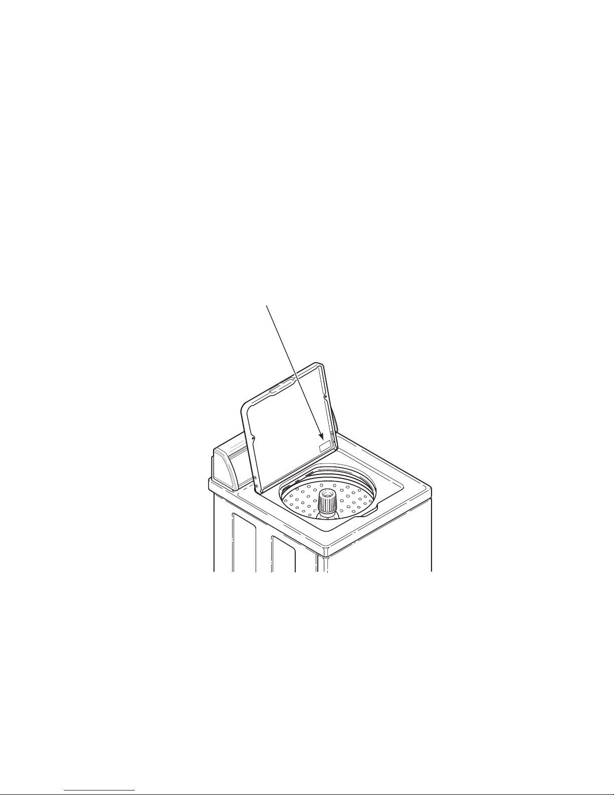
Nameplate Location
When calling or writing about your product, be sure to
mention model and serial numbers. Model and serial
numbers are located on nameplate(s) as shown.
8 203562
© Copyright, Alliance Laundry Systems LLC – DO NOT COPY or TRANSMIT
Section 3
To reduce the risk of electric shock, fire, explosion, serious injury or death:
• Disconnect electric power to the washer before servicing.
• Never start the washer with any guards/panels removed.
• Whenever ground wires are removed during servicing, these ground wires must be
reconnected to ensure that the washer is properly grounded.
W003
WARNING
Troubleshooting
Re
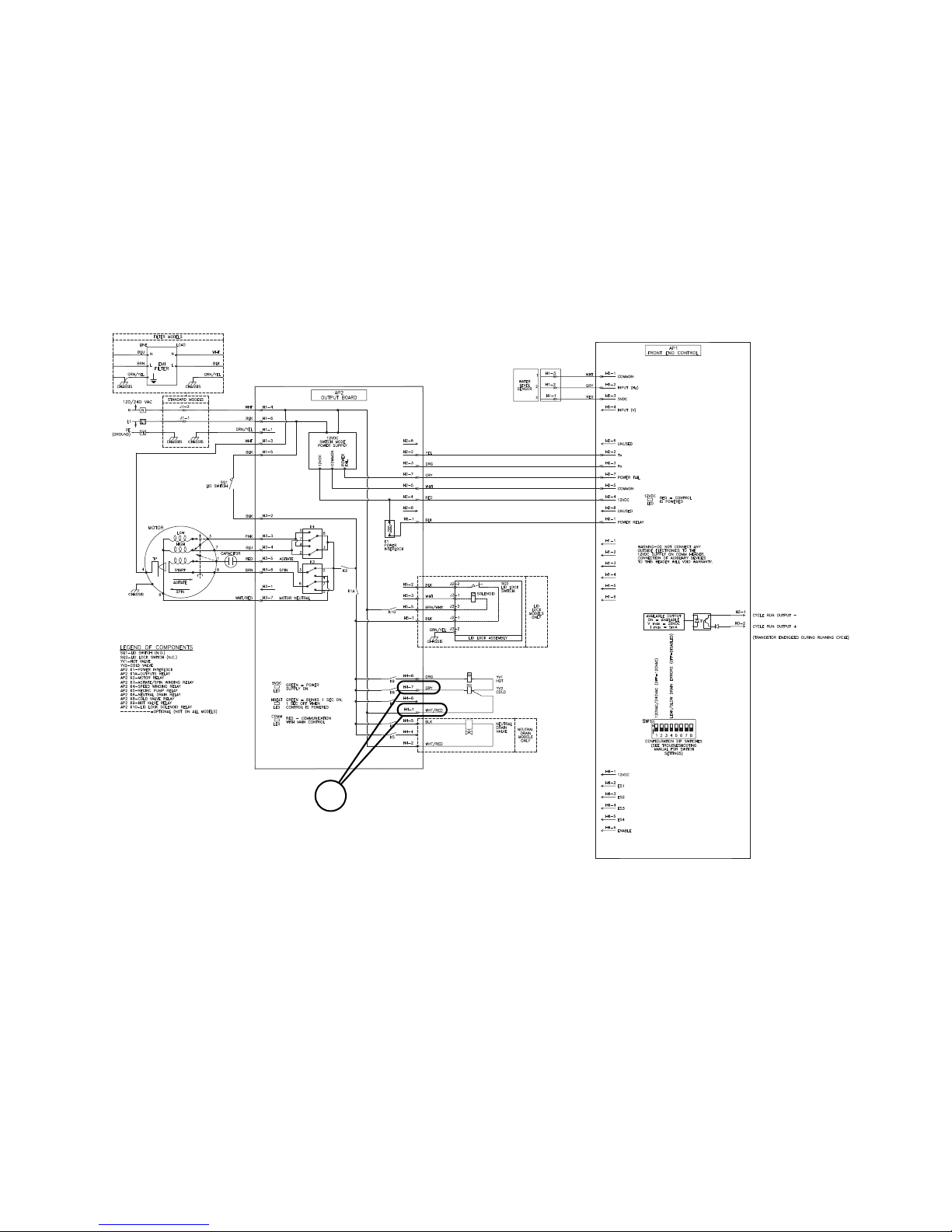
IMPORTANT: Refer to Wiring Diagram for aid in
testing washer components.
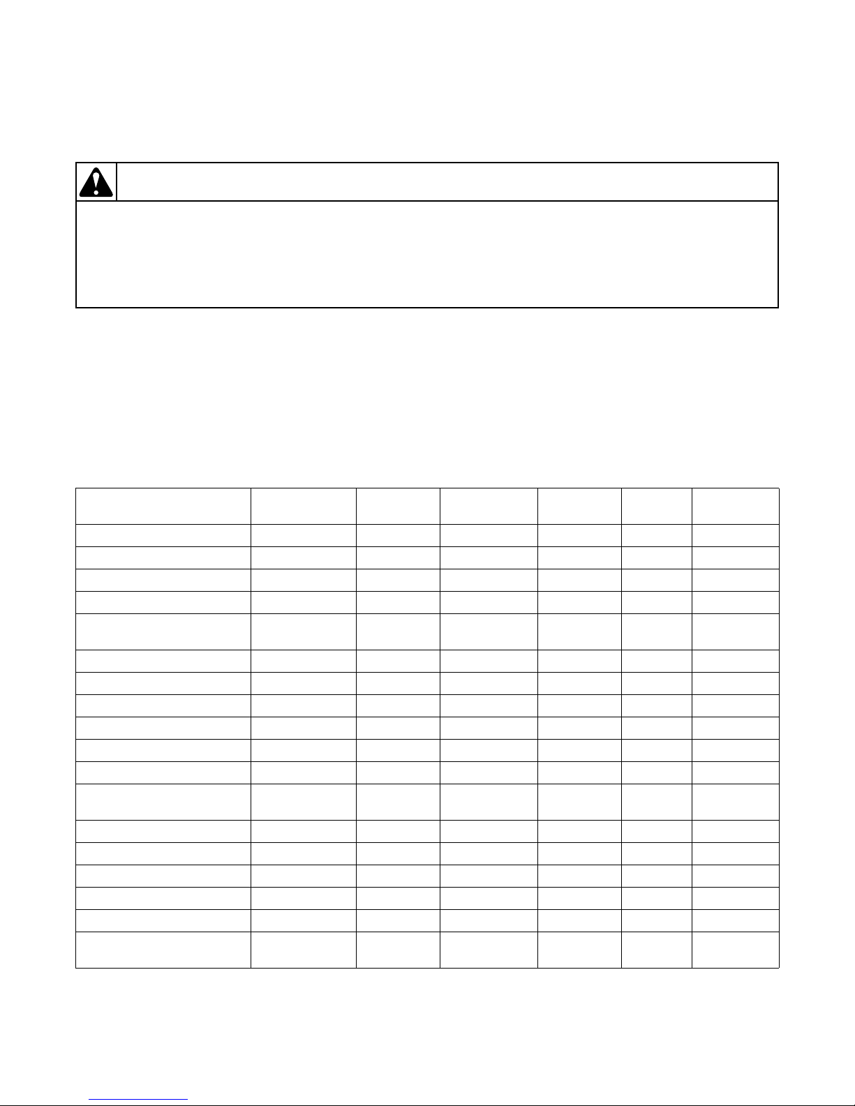
1. Production Test Summary
To enter Production Test Mode, disconnect machine
from electrical power and reconnect. Within five
minutes press keypads 2 and 7 (Refer to Figure 1) at the
same time.
Press the Start/Pause keypad to advance through the
steps.
Test Name Display LEDs Motor
Control Type “tL” All Off None Off Off Off
Control Firmware Major “XX”* All Off None Off Off Off
Output Board “ob” All Off None Off Off Off
Control Level “XX”* All Off None Off Off Off
CCB Region Display
Cycle Confirm
Control Dip Switches “XX”* All Off None Off Off Off
Keypad Test “PX” or “XX”* All Off None Off Off Off
Display Test “8.8” All On None Off On Off
High Speed Spin Test “01” Spin On High Speed Off Off Off
Hot Water Test “02” All Off None Hot Off Off
Cold Water Test “03” All Off None Cold Off Off
Warm Wat e r /
Pressure Sensor Test**
High Speed Agitate “05” Rinse On High Agitate Off Off Off
Low Speed Agitate “06” Rinse On Low Agitate Off Off Off
Low Speed Spin “07” Spin On Low Spin Off Off Off
High Speed Spin “08” Spin On High Spin Off Off Off
Warm Water Test “09” All Off None Hot, Cold Off Off
High Speed Spin/
Tub Empty Test
*“XX” displays number relating to test.
**This step will only advance automatically once specified water levels are reached.
“XX”* All Off None Off Off Off
“04” All Off None Hot, Cold Off Off
“10” Spin On High Spin Off Off Off
Table 1 (Continued)
Water
Va lv es
203562 9
© Copyright, Alliance Laundry Systems LLC – DO NOT COPY or TRANSMIT
Audio
Ton e
Auxilliary
Output
Troubleshooting
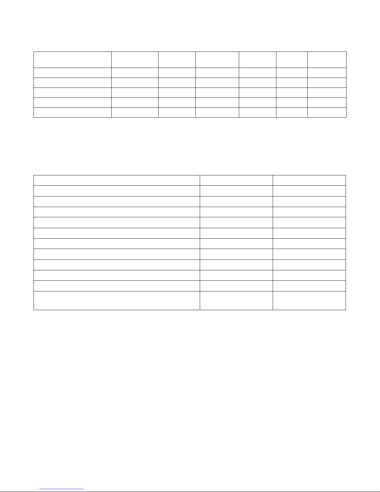
Table 1 (Continued)
Test Name Display LEDs Motor
Auxilliary 1 “11” All Off None Off Off Aux 1
Auxilliary 2 “12” All Off None Off Off Aux 2
Auxilliary 3 “13” All Off None Off Off Aux 3
Auxilliary 4 “14” All Off None Off Off Aux 4
Power Down “Pd” All Off None Off Off Off
*“XX” displays number relating to test.
**This step will only advance automatically once specified water levels are reached.
Tab le 1
Water
Va lv es
Audio
Ton e
2. Keypad Combinations
Refer to Figure 1.
Function Keys Entry state
Enter/Exit Software Version Display Mode 7+8 Start Mode
Enter Output Board Version Display 3+14 Start Mode
Rapid Advance 7+13 Run Mode
Enter/Exit Audit Display Mode 3+9 Start Mode
Auxilliary
Output
Enter Motor Thermal Protect Counter 7+9 Start Mode
Enter Production Test Mode 2+7 Start Mode under 5 min
Enter/Exit Production Test Counter 2+9 Start Mode
Toggle Keypad Acknowledgement 13+14 Start Mode
Turn On/Off Rainbow Pizzazz display 9+10 Start Mode
Enter/Exit Show Mode 3+8 Start Mode
Pressure Sensor Display 4+14
Tab le 2
Any Mode Except
Errors
10 203562
© Copyright, Alliance Laundry Systems LLC – DO NOT COPY or TRANSMIT
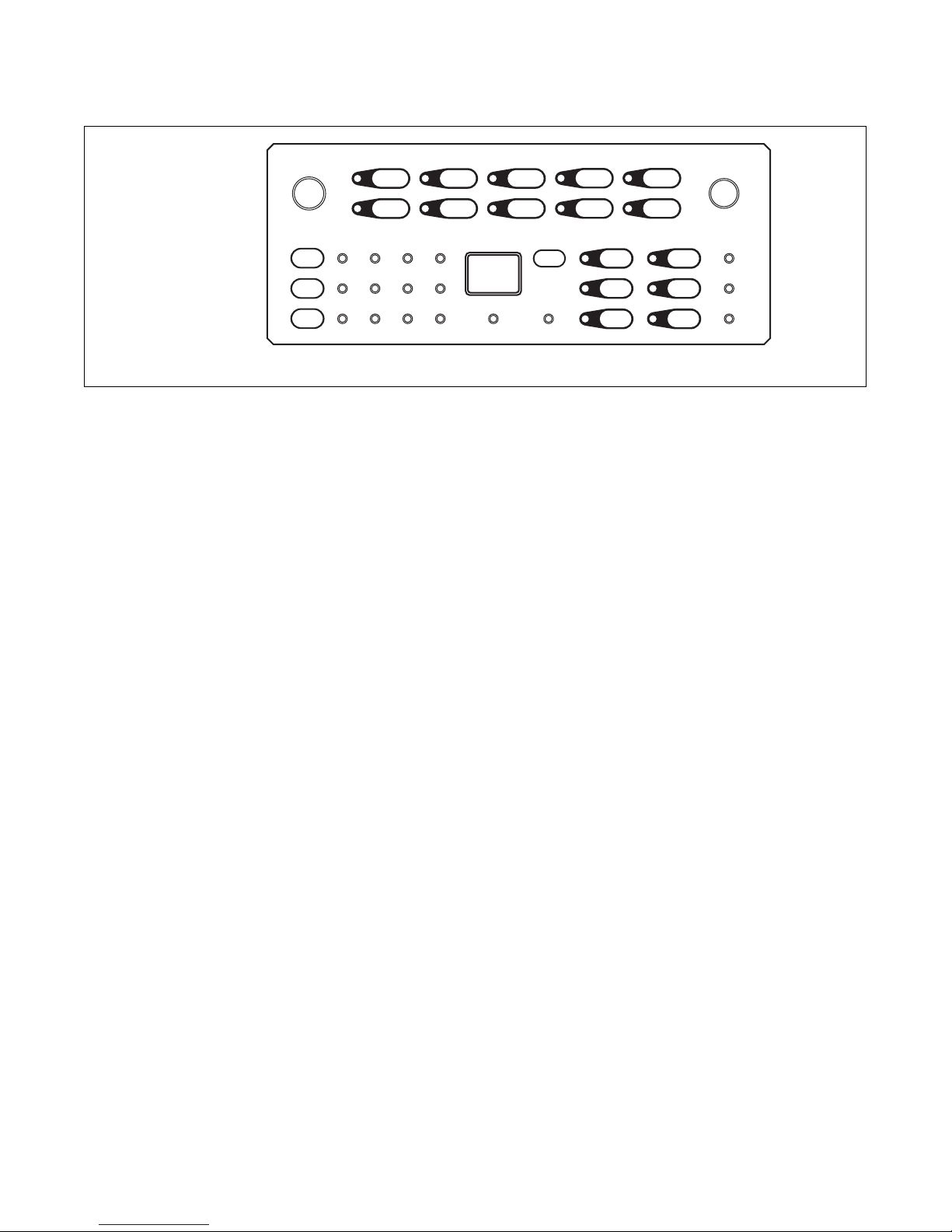
3. Rapid Advance
TLW432S
5 7 9 13 18
6 8 10 14 19
11 15 20
16 21
17 22
2
3
4
1
23
For Rapid Advance press keypads 7 and 13 at the same
time to advance to the next step of the cycle. Each time
these keypads are pressed the cycle will advance to the
next step. Then press them both again to advance
through the cycle. Refer to Cycle Sequence Charts
section for each cycle step. Fill/Agitate cycle steps
count as one Rapid Advance step.
Troubleshooting
TLW432S
Figure 1
5. Low Water Level on High Fill
Setting
a. If there is an instance of a low water level on the
highest fill setting, check that the high setting
water level is between 12 and 13.5 inches.
b. If the water level is within .5 inch of this level
without clothes, it is performing as designed.
4. Control Version Display
a. To display the software version, press keypads
7 and 8 at the same time.
b. To display the output board version, press
keypads 3 and 14 at the same time.
203562 11
© Copyright, Alliance Laundry Systems LLC – DO NOT COPY or TRANSMIT
Troubleshooting
TLW457S
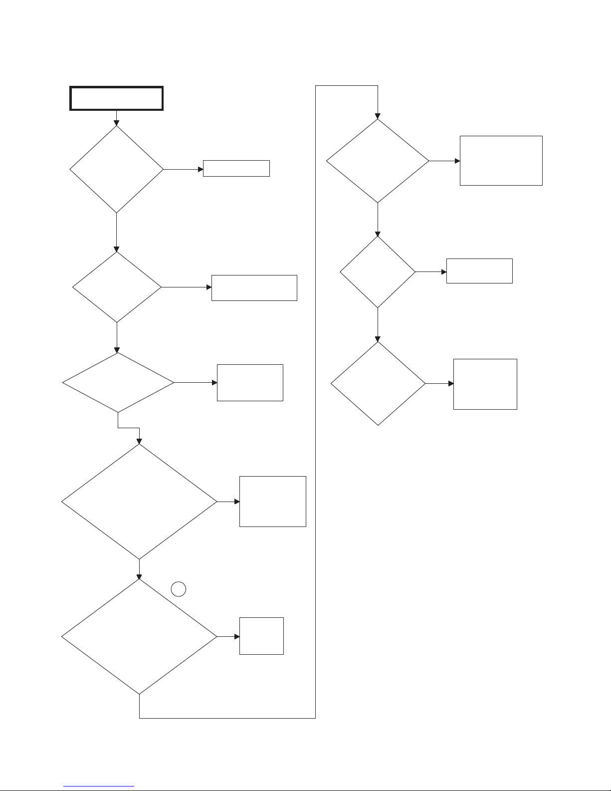
6. No Hot Water - “Er”, “FL”
There is no hot water.
Is the water
supply faucet
closed?
No
Is the water
supply cold?
No
Is the hot water
fill hose kinked?
No
Yes
Yes
Yes
Open faucet.
Check water heater.
Straighten or
replace hose.
Is there
voltage at the
Hot Solenoid?
Yes
Is
Hot Solenoid
inoperative?
No
Is
pressure hose
clogged or
damaged?
Yes
No
Replace valve.
Remove and
Yes
clean or
replace hose.
Check wiring
from output board
to water valve.
Is the mixing valve
screen or screen in
outer end of fill hose
nearest water supply
faucet clogged?
No
1
Is
there voltage
output from output
board to the Hot Solenoid
at “H4-8” and
“H4-1”?
Yes
12 203562
© Copyright, Alliance Laundry Systems LLC – DO NOT COPY or TRANSMIT
Disconnect hot
Yes
fill hose and
clean or
replace screen.
Replace
No
output
board.
TLW457S

No Hot Water - “Er”, “FL”
TLW456S
1
Troubleshooting
203562 13
© Copyright, Alliance Laundry Systems LLC – DO NOT COPY or TRANSMIT

Troubleshooting
There is no cold
water.
Is the water
supply faucet
closed?
Open faucet.
Yes
Is the cold
water fill hose
kinked?
Straighten or
replace hose.
Yes
Is the mixing valve
screen or screen in
outer end of fill hose
nearest water supply
faucet clogged?
No
Disconnect
cold fill hose
and clean or
replace screen.
Yes
Is
there voltage
at the output board to
the Cold Solenoid
at “H4-7” and
“H4-1”
?
No
Replace
output
board.
No
No
Replace valve.
Is Cold
Solenoid
inoperative?
Yes
Yes
Yes
No
TLW458S
No
Yes
Is
pressure
hose clogged
or damaged?
Remove and
clean or
replace hose.
Is
there voltage
to the Cold
Solenoid?
Check wiring from
output board to
water solenoid.
1
TLW458S
7. No Cold Water - “Er”, “FL”
14 203562
© Copyright, Alliance Laundry Systems LLC – DO NOT COPY or TRANSMIT
No Cold Water - “Er”, “FL”
TLW456S
1
Troubleshooting
203562 15
© Copyright, Alliance Laundry Systems LLC – DO NOT COPY or TRANSMIT
Troubleshooting
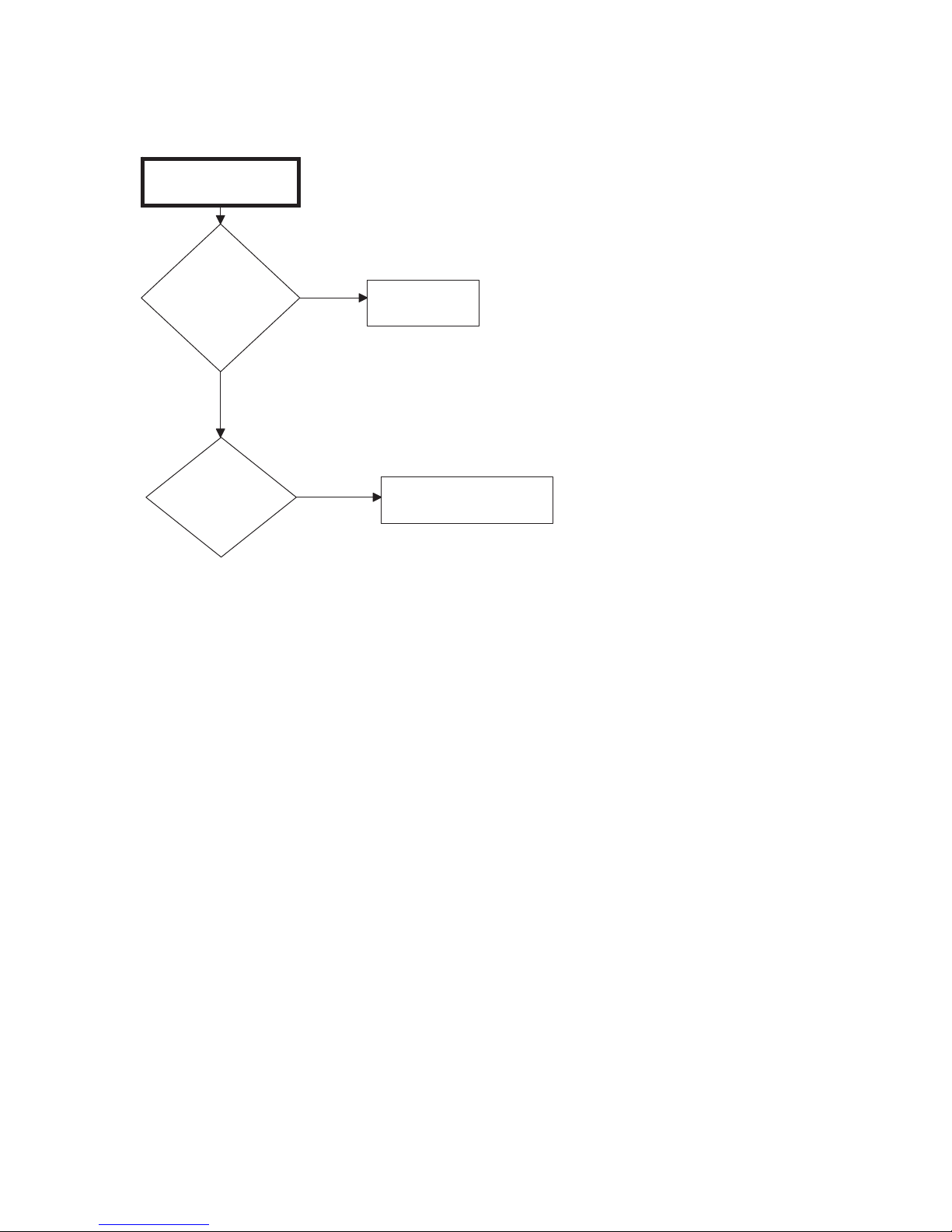
There is no warm
water.
Is there no
hot water?
Refer to
Paragraph 1.
Yes
Is there no
cold water?
No
Refer to Paragraph 2.
Yes
TLW328S
8. No Warm Water - “Er”, “FL”
16 203562
© Copyright, Alliance Laundry Systems LLC – DO NOT COPY or TRANSMIT
 Loading...