

Page 1
Washer-Extractor
PHM1397C_C002923
Refer to Page 5 for Model Numbers
Parts
www.alliancelaundry.com
Part No. C002923R8
November 2015
Page 2

Page 3

Table of Contents
Title Page
Parts Ordering Information........................................................................................................................................ 3
Serial Plate Location ................................................................................................................................................. 3
Model Identification ................................................................................................................................................... 5
Product Overview - PS40 Control ............................................................................................................................. 6
Decals - Models through 8/31/09 (Drawing 1 of 2) ................................................................................................... 8
Decals - Models through 8/31/09 (Drawing 2 of 2) ................................................................................................. 10
Decals - Models starting 9/1/09 .............................................................................................................................. 12
Bearing Housing Assembly (Drawing 1 of 6) .......................................................................................................... 14
Bearing Housing Assembly (Drawing 2 of 6) .......................................................................................................... 16
Bearing Housing Assembly (Drawing 3 of 6) .......................................................................................................... 18
Bearing Housing Assembly (Drawing 4 of 6) .......................................................................................................... 20
Bearing Housing Assembly (Drawing 5 of 6) .......................................................................................................... 22
Bearing Housing Assembly (Drawing 6 of 6) .......................................................................................................... 24
Cabinet Assembly (Drawing 1 of 4) ........................................................................................................................ 26
Cabinet Assembly (Drawing 2 of 4) ........................................................................................................................ 28
Cabinet Assembly (Drawing 3 of 4) ........................................................................................................................ 30
Cabinet Assembly (Drawing 4 of 4) ........................................................................................................................ 32
Cylinder Assembly (Drawing 1 of 2)........................................................................................................................ 34
Cylinder Assembly (Drawing 2 of 2)........................................................................................................................ 36
Single Cup Dispenser Assembly............................................................................................................................. 38
5 Cup Dispenser Assembly..................................................................................................................................... 40
Door Assembly - Models through 2/9/09................................................................................................................. 42
Door Assembly - Models starting 2/10/09 ............................................................................................................... 44
Door Lock................................................................................................................................................................ 46
Door Lock Assembly with Magnetic Sensor ............................................................................................................ 48
5 Cup Hot Plumbing Assembly ............................................................................................................................... 50
1 Cup Hot Plumbing Assembly ............................................................................................................................... 52
5 Cup Cold Plumbing Assembly (Drawing 1 of 3) ................................................................................................... 54
5 Cup Cold Plumbing Assembly (Drawing 2 of 3) ................................................................................................... 56
5 Cup Cold Plumbing Assembly (Drawing 3 of 3) ................................................................................................... 58
Single Cup Cold Plumbing Assembly (Drawing 1 of 3) ........................................................................................... 60
Single Cup Cold Plumbing Assembly (Drawing 2 of 3) ........................................................................................... 62
Single Cup Cold Plumbing Assembly (Drawing 3 of 3) ........................................................................................... 64
Auxiliary Plumbing Assembly with Valve................................................................................................................. 66
Auxiliary Plumbing Assembly without Valve (Drawing 1 of 2) ................................................................................. 68
Auxiliary Plumbing Assembly without Valve (Drawing 2 of 2) ................................................................................. 70
Hot and Auxiliary Plumbing Assembly with Valve (Drawing 1 of 2) ........................................................................ 72
Hot and Auxiliary Plumbing Assembly with Valve (Drawing 2 of 2) ........................................................................ 74
Steam Heat Assembly ............................................................................................................................................ 76
Shell Assembly (Drawing 1 of 2) ............................................................................................................................. 78
Shell Assembly (Drawing 2 of 2) ............................................................................................................................. 80
© Copyright 2015, Alliance Laundry Systems LLC
All rights reserved. No part of the contents of this book may be reproduced or transmitted in any form or by any
means without the expressed written consent of the publisher.
C002923 1
© Copyright, Alliance Laundry Systems LLC – DO NOT COPY or TRANSMIT
Page 4

Control Box Assembly............................................................................................................................................. 82
Drive Box Assembly (Drawing 1 of 2) ..................................................................................................................... 84
Drive Box Assembly (Drawing 2 of 2) ..................................................................................................................... 86
Electric Heat Drive Box Assembly .......................................................................................................................... 88
PowerFlex Drive and EMI Filter (Drawing 1 of 2).................................................................................................... 90
PowerFlex Drive and EMI Filter (Drawing 2 of 2).................................................................................................... 92
Main Assembly (Drawing 1 of 10) ........................................................................................................................... 94
Main Assembly (Drawing 2 of 10) ........................................................................................................................... 96
Main Assembly (Drawing 3 of 10) ........................................................................................................................... 98
Main Assembly (Drawing 4 of 10) ......................................................................................................................... 100
Main Assembly (Drawing 5 of 10) ......................................................................................................................... 102
Main Assembly (Drawing 6 of 10) ......................................................................................................................... 104
Main Assembly (Drawing 7 of 10) ......................................................................................................................... 106
Main Assembly (Drawing 8 of 10) ......................................................................................................................... 108
Main Assembly (Drawing 9 of 10) ......................................................................................................................... 110
Main Assembly (Drawing 10 of 10) ....................................................................................................................... 112
Parts Index ............................................................................................................................................................ 115
2 C002923
© Copyright, Alliance Laundry Systems LLC – DO NOT COPY or TRANSMIT
Page 5
Parts Ordering Information
PHM1397CA_C002923
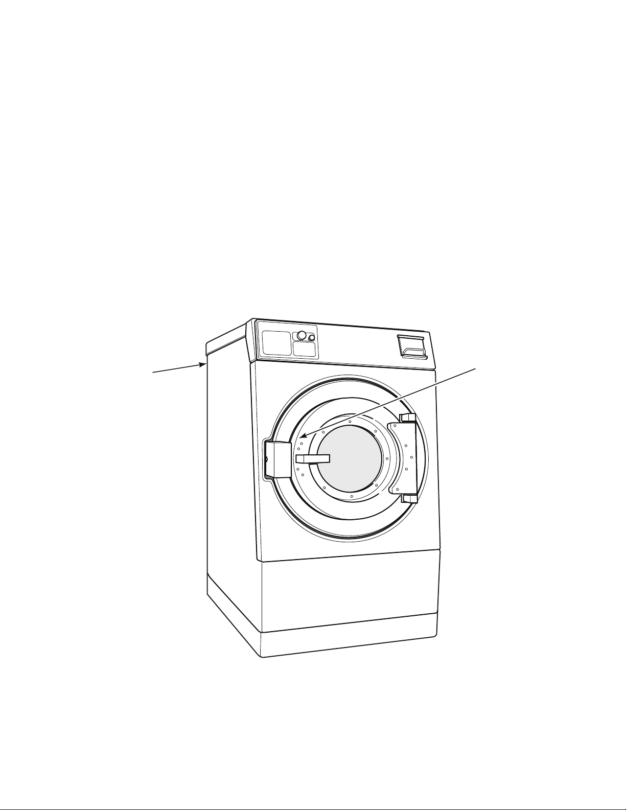
Serial Plate
Serial Plate
If literature or replacement parts are required, contact the source from whom the machine was purchased or contact Alliance Laundry Systems at
(920) 748-3950 for the name and address of the
nearest authorized parts distributor.
Serial Plate Location
When calling or writing about your product, be
sure to mention model and serial numbers. Model
and serial numbers are located on serial plate(s)
as shown. The serial plate is located inside the
door and on the upper rear panel.
For technical assistance, call either of the numbers listed below:
(920) 748-3121 Ripon, Wisconsin
+32 56 41 20 54 Wevelgem, Belgium
C002923 3
© Copyright, Alliance Laundry Systems LLC – DO NOT COPY or TRANSMIT
Page 6

Notes
4 C002923
© Copyright, Alliance Laundry Systems LLC – DO NOT COPY or TRANSMIT
Page 7

Model Identification
Information in this manual is applicable to these washer-extractor models:
CPC125H
CPC140H
CPC140M
CP125PHN1
CP125PHN2
CP125PHQ1
CP125PHQ2
CP140PHN1
CP140PHQ1
CP140PMN1
CP140PMQ1
IPH125H
IPH140H
IPH140M
IPH570
IPH640
IP125PHN1
IP125PHN2
IP125PHQ1
IP125PHQ2
IP140PHN1
IP140PHQ1
IP140PMN1
IP140PMQ1
JP125PHN1
JP125PHN2
JP140PHN1
JP140PHQ1
JP140PMQ1
C002923 5
© Copyright, Alliance Laundry Systems LLC – DO NOT COPY or TRANSMIT
Page 8
Product Overview - PS40 Control
1 2 3
4 5 6
7 8 9
0
PS40
PROG
RUN
PHM3091P_C002923
00000000000
208 – 240
3
Hz Phase
Supply Water: BAR
Number of wires : FLA : amps
3
Circuit Breaker Size : amps
60 3
Serial No.
Model No.
Voltage
40
30 - 85 psi, 2 - 5.7
Max. Load :
Schematic :
KG
18.2
LB
*P040PHQ1001U01
6 C002923
© Copyright, Alliance Laundry Systems LLC – DO NOT COPY or TRANSMIT
Page 9

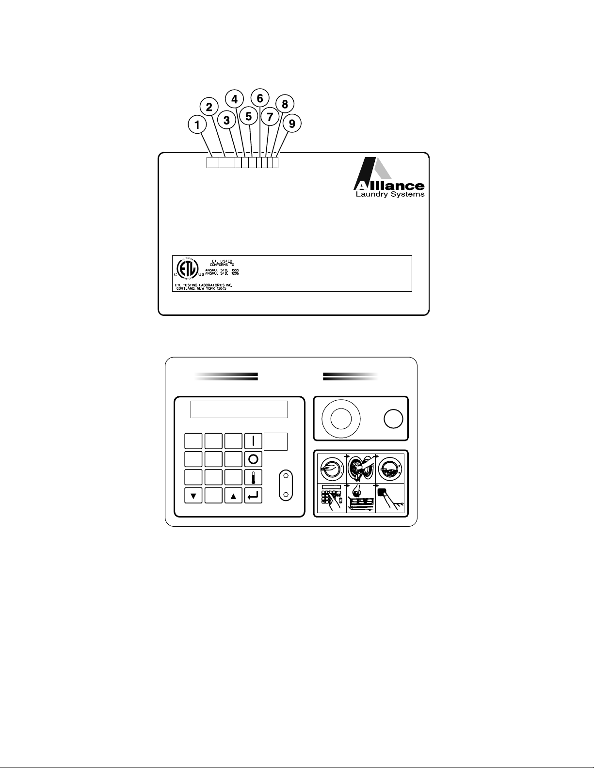
Product Overview - PS40 Control
REF PART NO. DESCRIPTION COMMENTS
1 Product Family CP
IP
JP
2 Capacity (Pounds) 040
060
080
100
125
140
175
3 Control P (PS-40 Control)
4 Speed H (High Speed)
M (Medium Speed)
5 Voltage N (380-415/440-480/50/60/3)
Q (208-220/220-240/50/60/3)
X (208-220/220-240/50/60/1/3)
6 Design 1
2
7 Heat 0 (Prep for Steam)
D (Direct)
E (Electric)
8 Plumbing 0 (Standard US Thread - 2 valves)
A (US Thread - 3 valves)
B (Metric Thread - 2 valves)
C (Metric Thread - 3 valves)
D (US Thread - 2 valves, 3 inlets)
E (No valves)
9 Supply 1 (1 Compartment 6 Signals)
2 (1 Compartment 12 Signals)
5 (5 Compartments 6 Signals)
6 (5 Compartments 12 Signals)
7 (No Compartment 6 Signals)
8 (No Compartment 12 Signals)
C002923 7
© Copyright, Alliance Laundry Systems LLC – DO NOT COPY or TRANSMIT
Page 10
Decals - Models through 8/31/09 (Drawing 1 of 2)
PHM2767P_C002923
8 C002923
© Copyright, Alliance Laundry Systems LLC – DO NOT COPY or TRANSMIT
Page 11

Decals - Models through 8/31/09 (Drawing 1 of 2)
REF PART NO. DESCRIPTION COMMENTS
1 F200085100 Spin Warning Decal Models CP125PHN1, CP125PHQ1, CP140PHN1,
CP140PHQ1, CP140PMN1, CP140PMQ1, IP125PHN1,
IP125PHQ1, IP140PHN1, IP140PHQ1, IP140PMN1,
IP140PMQ1, JP125PHN1, JP140PHN1, JP140PHQ1
and JP140PMQ1
2 F200085000 Hot Surface Warning Decal Models CP125PHN1, CP125PHQ1, CP140PHN1,
CP140PHQ1, CP140PMN1, CP140PMQ1, IP125PHN1,
IP125PHQ1, IP140PHN1, IP140PHQ1, IP140PMN1,
IP140PMQ1, JP125PHN1, JP140PHN1, JP140PHQ1
and JP140PMQ1
3 F200085300 Hot Water and Chemical Caution
Decal
4 F200318200 Cover Decal
5 F230734 Water Line Caution Decal Models CP125PHN1, CP125PHQ1, CP140PHN1,
6 F231367 Hot Water Valve Decal
7 F231368 Cold Water Valve Decal
8 C000508 Bearing Lubrication Decal
9 C000506 Supply Signal Decal Models starting 3/23/04
10 F230917-1 External Supply Connection Decal Models CP125PHN1, CP125PHQ1, CP140PHN1,
Models CP125PHN1, CP125PHQ1, CP140PHN1,
CP140PHQ1, CP140PMN1, CP140PMQ1, IP125PHN1,
IP125PHQ1, IP140PHN1, IP140PHQ1, IP140PMN1,
IP140PMQ1, JP125PHN1, JP140PHN1, JP140PHQ1
and JP140PMQ1
CP140PHQ1, CP140PMN1, CP140PMQ1, IP125PHN1,
IP125PHQ1, IP140PHN1, IP140PHQ1, IP140PMN1,
IP140PMQ1, JP125PHN1, JP140PHN1, JP140PHQ1
and JP140PMQ1
CP140PHQ1, CP140PMN1, CP140PMQ1, IP125PHN1,
IP125PHQ1, IP140PHN1, IP140PHQ1, IP140PMN1,
IP140PMQ1, JP125PHN1, JP140PHN1, JP140PHQ1
and JP140PMQ1
C002923 9
© Copyright, Alliance Laundry Systems LLC – DO NOT COPY or TRANSMIT
Page 12
Decals - Models through 8/31/09 (Drawing 2 of 2)
PHM2767PA_C002923
10 C002923
© Copyright, Alliance Laundry Systems LLC – DO NOT COPY or TRANSMIT
Page 13

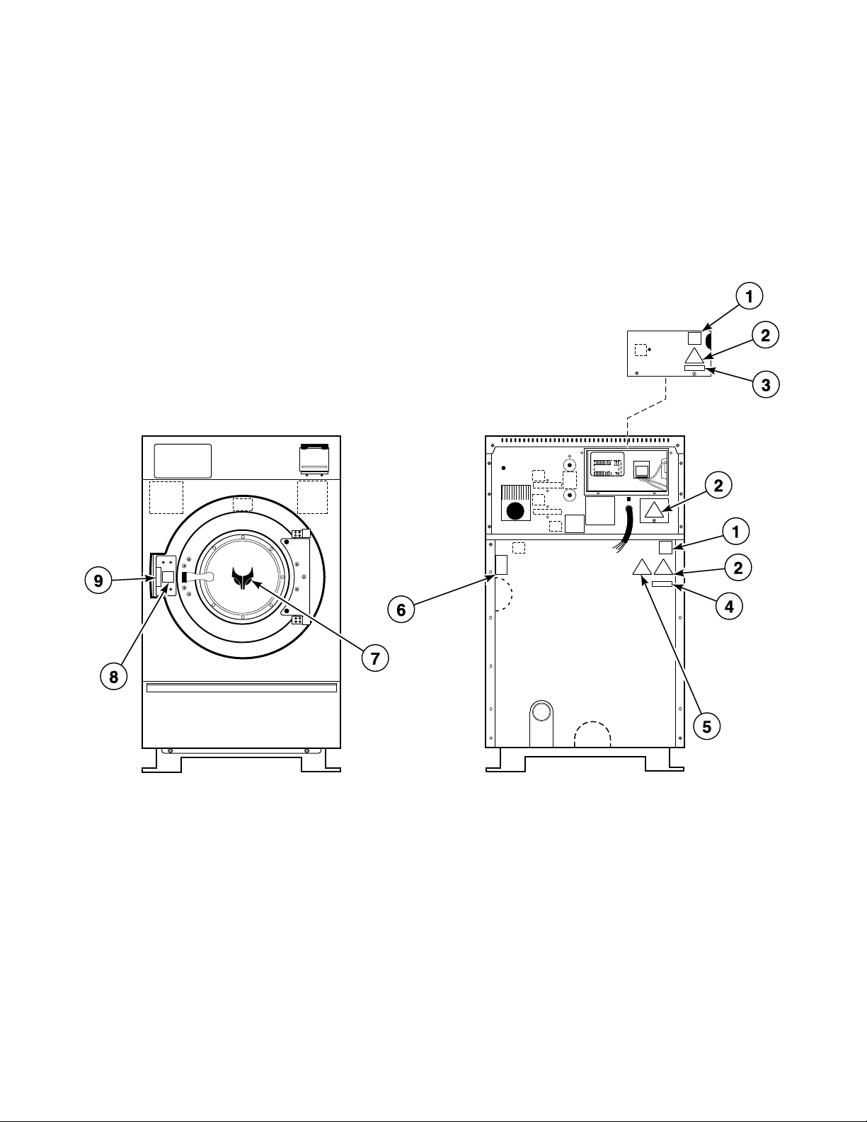
Decals - Models through 8/31/09 (Drawing 2 of 2)
REF PART NO. DESCRIPTION COMMENTS
1 F200318200 Cover Decal
2 502511 Electrical Shock Label
3 505281 Disconnect Power Warning Label Models CP125PHN1, CP125PHQ1, CP140PHN1,
CP140PHQ1, CP140PMN1, CP140PMQ1, IP125PHN1,
IP125PHQ1, IP140PHN1, IP140PHQ1, IP140PMN1,
IP140PMQ1, JP125PHN1, JP140PHN1, JP140PHQ1 and
JP140PMQ1
4 500049 Warning Label Models CP125PHN1, CP125PHQ1, CP140PHN1,
CP140PHQ1, CP140PMN1, CP140PMQ1, IP125PHN1,
IP125PHQ1, IP140PHN1, IP140PHQ1, IP140PMN1,
IP140PMQ1, JP125PHN1, JP140PHN1, JP140PHQ1 and
JP140PMQ1
5 N/A Crush Hazard Warning Decal Models CPC125H, CPC140H, CPC140M, IPH125H,
IPH140H, IPH140M, IPH570 and IPH640
5 502506 Pinched Fingers Label Models CP125PHN1, CP125PHQ1, CP140PHN1,
CP140PHQ1, CP140PMN1, CP140PMQ1, IP125PHN1,
IP125PHQ1, IP140PHN1, IP140PHQ1, IP140PMN1,
IP140PMQ1, JP125PHN1, JP140PHN1, JP140PHQ1 and
JP140PMQ1
6 F231380 Hot Surface Warning Decal
7 C001038 Logo Decal Models IPH125H, IPH140H, IPH140M, IPH570, IPH640,
IP125PHN1, IP125PHQ1, IP140PHN1, IP140PHQ1,
IP140PMN1 and IP140PMQ1
8 C000694 Door Release Decal
9 F230303 Push Decal Models CP125PHN1, CP125PHQ1, CP140PHN1,
CP140PHQ1, CP140PMN1, CP140PMQ1, IP125PHN1,
IP125PHQ1, IP140PHN1, IP140PHQ1, IP140PMN1,
IP140PMQ1, JP125PHN1, JP140PHN1, JP140PHQ1 and
JP140PMQ1
N/A = Part no longer available
C002923 11
© Copyright, Alliance Laundry Systems LLC – DO NOT COPY or TRANSMIT
Page 14
Decals - Models starting 9/1/09
PHM3089P_C002923
Models CP125PHN1, CP125PHN2, CP125PHQ1, CP125PHQ2, CP140PHN1, CP140PHQ1, CP140PMN1,
CP140PMQ1, IP125PHN1, IP125PHN2, IP125PHQ1, IP125PHQ2, IP140PHN1, IP140PHQ1, IP140PMN1,
IP140PMQ1, JP125PHN1, JP125PHN2, JP140PHN1, JP140PHQ1 and JP140PMQ1
12 C002923
© Copyright, Alliance Laundry Systems LLC – DO NOT COPY or TRANSMIT
Page 15

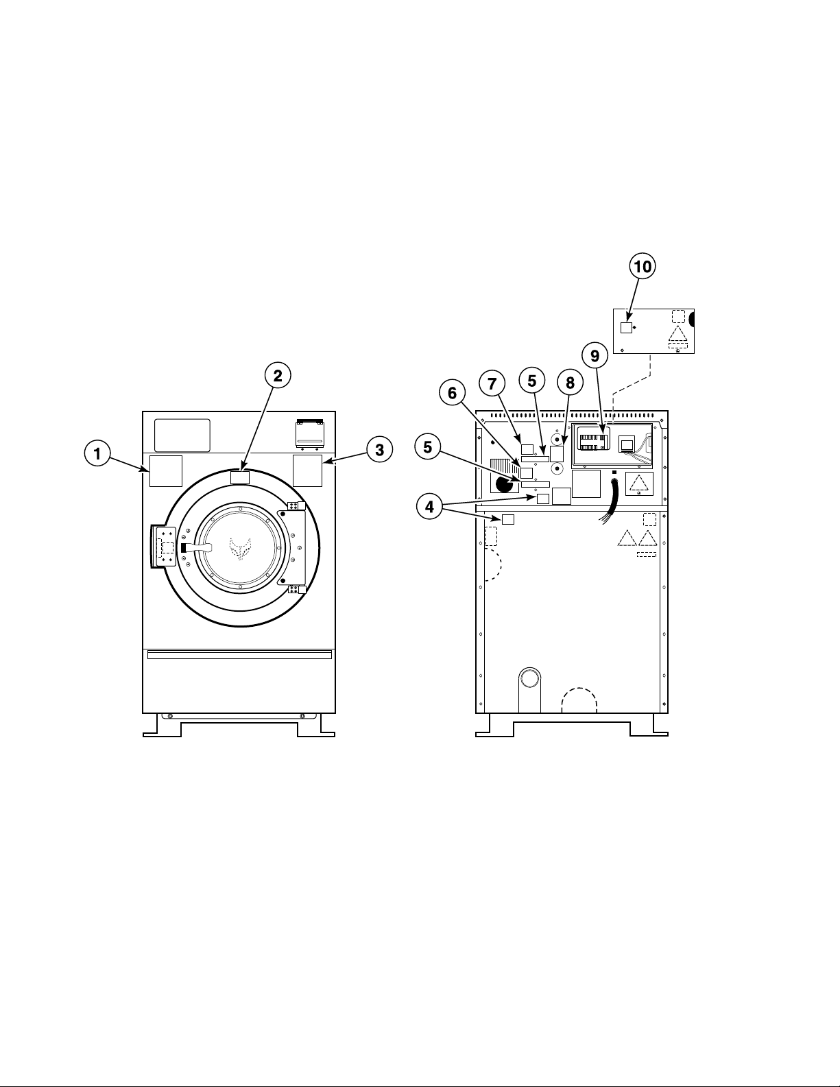
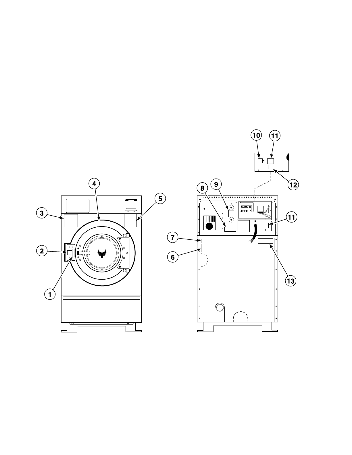
Decals - Models starting 9/1/09
REF PART NO. DESCRIPTION COMMENTS
1 C000694 Door Release Decal
2 F230303 Push Decal
3 F200085100 Spin Warning Decal
4 F200085000 Hot Surface Warning Decal
5 F200085300 Hot Water and Chemical Caution Decal
6 F8211901 Hot Surface Warning Plate Steam models only
7 F8246401 Mount on Concrete Warning Label
8 F200061000 Clean Filter Daily Decal
9 C000508 Bearing Lubrication Decal
10 F8150201 External Supply Connection Decal
11 F8233501 Warning Label
12 F8115501 Electric Shock Danger Label
13 44127701 Warning Label
C002923 13
© Copyright, Alliance Laundry Systems LLC – DO NOT COPY or TRANSMIT
Page 16
Bearing Housing Assembly (Drawing 1 of 6)
PHM2848P_C002923
Models CPC140H and IPH140H
Models Through 3/23/04
14 C002923
© Copyright, Alliance Laundry Systems LLC – DO NOT COPY or TRANSMIT
Page 17

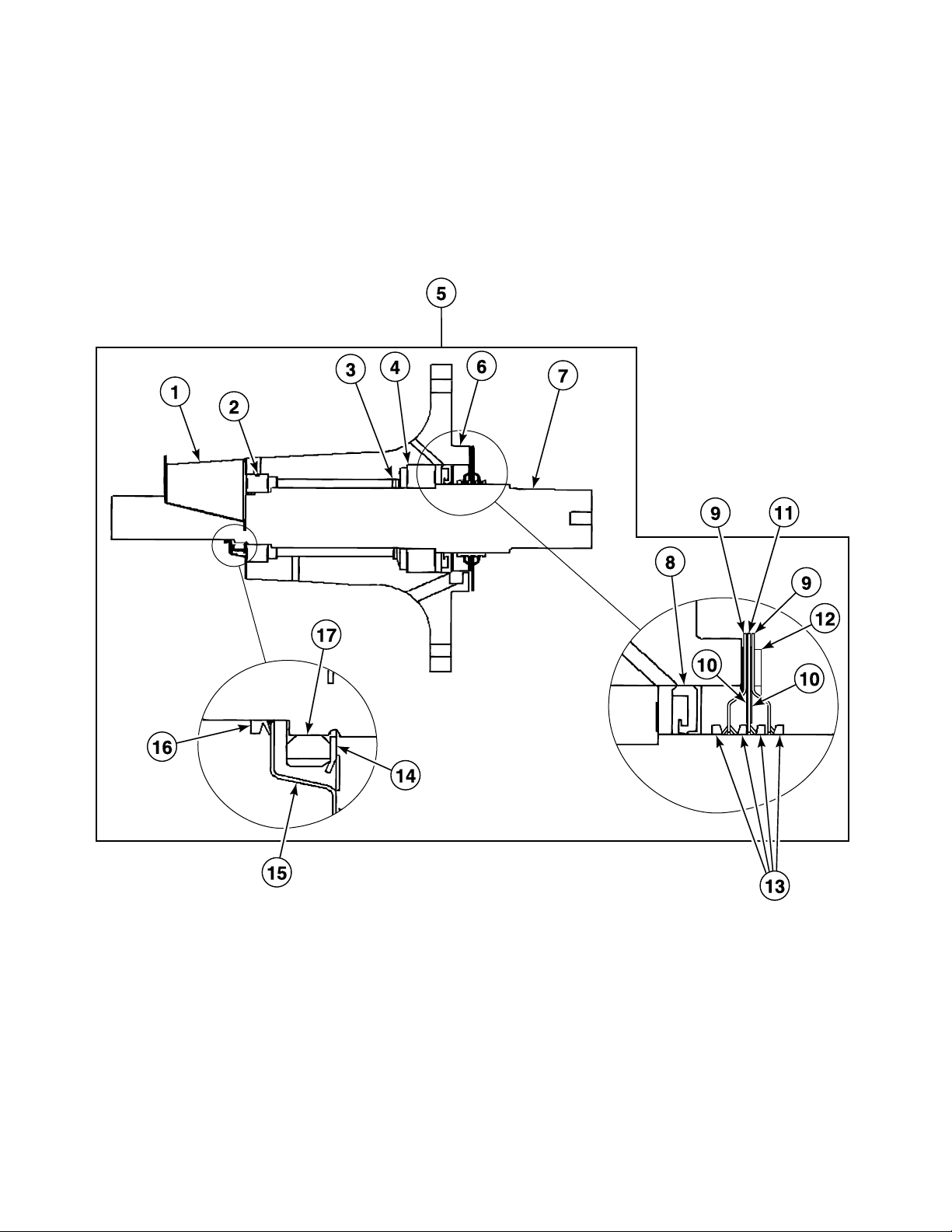
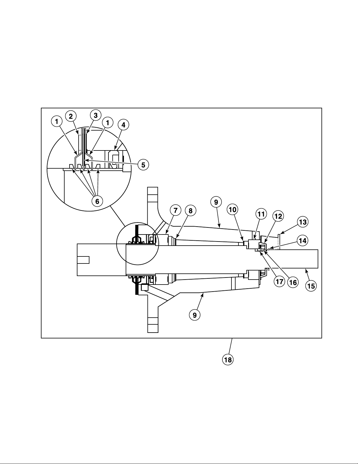
Bearing Housing Assembly (Drawing 1 of 6)
REF PART NO. DESCRIPTION COMMENTS
NA C001020 Screw 8 required; Bearing housing to frame
NA C001021 Washer 8 required; Bearing housing to frame
NA F430929 Screw 6 required for rear seal plate to bearing housing; 6
required for front seal plates to bearing housing
NA C000571 Washer 6 required for rear seal plate to bearing housing; 6
required for front seal plates to bearing housing
NA C002637P Proximity Switch Assembly 1 required; Proximity switch on bearing housing
NA C000552 Hose 1 required; 26 inch; Weep hole fitting to drain line fitting
NA 36801 Hose Clamp 1 required; Bearing weep hole “TEE”
1 C000969 Proximity Mounting Bracket
2 F100155 Bearing
3 C000758 Grease Shield 2 required
4 C000762 Carb Bearing
5 C000673P Bearing Housing Assembly
6 C000672 Bearing Housing
7 C000674 Cylinder Shaft
8 C000761 Front Bearing Lip Seal
9 C000754 Seal Plate 2 required
10 C001706 Seal Plate Gasket
11 C000755 Seal Plate
12 C001914 Backup Seal Plate
13 C000757 V-Ring Seal 4 required
14 C000764 Washer
15 C000756 Seal Plate
16 C000765 V-Ring Seal
17 C000763 Nut
C002923 15
© Copyright, Alliance Laundry Systems LLC – DO NOT COPY or TRANSMIT
Page 18
Bearing Housing Assembly (Drawing 2 of 6)
PHM2798P_C002923
Models CPC140H and IPH140H
Models Starting 3/23/04
16 C002923
© Copyright, Alliance Laundry Systems LLC – DO NOT COPY or TRANSMIT
Page 19

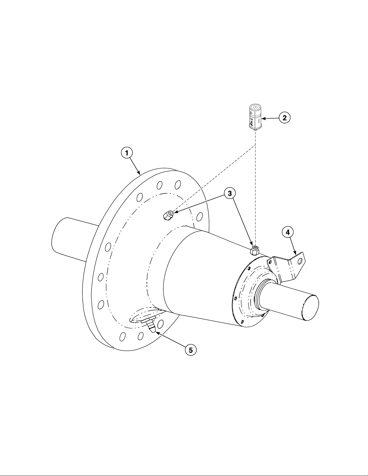
Bearing Housing Assembly (Drawing 2 of 6)
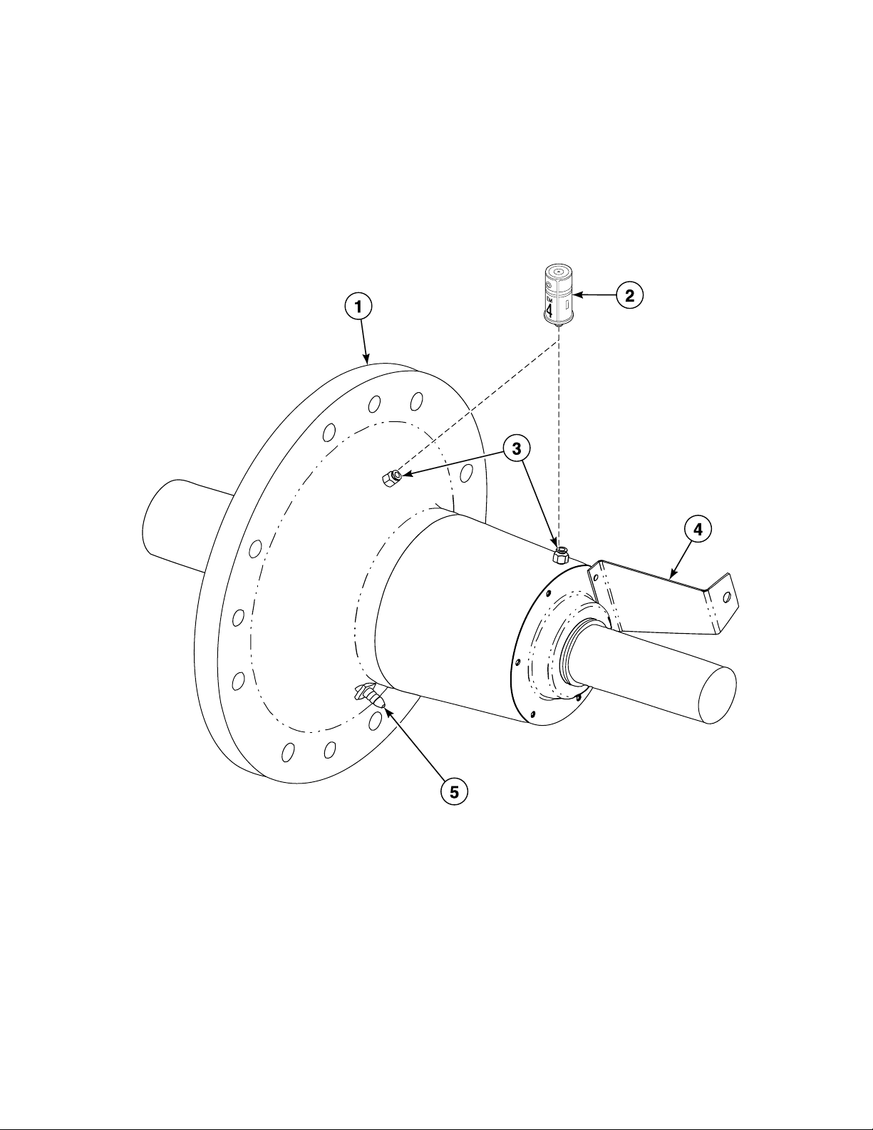
REF PART NO. DESCRIPTION COMMENTS
NA C001020 Screw 8 required; Bearing housing to frame
NA C001021 Washer 8 required; Bearing housing to frame
NA F430929 Screw 6 required for rear seal plate to bearing housing; 6
required for front seal plates to bearing housing
NA C000571 Washer 6 required for rear seal plate to bearing housing; 6
required for front seal plates to bearing housing
NA C002637P Proximity Switch Assembly 1 required; Proximity switch on bearing housing
NA C000552 Hose 1 required; 26 inch; Weep hole fitting to drain line fitting
NA C000628P Tubing 2 required; 33 inch; Lube fittings to bearing housing
NA 1390P Bearing Housing Puller Kit Purchase
NA 1390-1 Bearing Housing Puller Kit Rental; Requires C002023 Hardware Kit
NA C002023 Hardware Kit
NA 36801 Hose Clamp 1 required; Bearing weep hole “TEE”
1 C000673P Bearing Housing Assembly Standard seals
1 C001946 Bearing Housing Assembly Viton seals
2 212/00022/00 Lubricator
3 J1408004 Connector 2 required
4 C000969 Proximity Mounting Bracket
5 C001649 Reducing Connector
C002923 17
© Copyright, Alliance Laundry Systems LLC – DO NOT COPY or TRANSMIT
Page 20
Bearing Housing Assembly (Drawing 3 of 6)
PHM2724P_C002923
Models CPC140M, IPH140M and IPH640
Models Through 3/23/04
18 C002923
© Copyright, Alliance Laundry Systems LLC – DO NOT COPY or TRANSMIT
Page 21

Bearing Housing Assembly (Drawing 3 of 6)
REF PART NO. DESCRIPTION COMMENTS
NA C000554 Screw 8 required; Bearing housing to frame
NA C000555 Washer 8 required; Bearing housing to frame
NA F430929 Screw 6 required for rear seal plate to bearing housing; 6
required for front seal plates to bearing housing
NA C000571 Washer 6 required for rear seal plate to bearing housing; 6
required for front seal plates to bearing housing
NA C002637P Proximity Switch Assembly 1 required; Proximity switch on bearing housing
NA C000552 Hose 1 required; 26 inch; Weep hole fitting to drain line fitting
NA 36801 Hose Clamp 1 required; Bearing weep hole “TEE”
1 C000166 Seal Plate 2 required
2 C001915 Plate
3 C001705 Gasket
4 C000332 Lip Seal Front bearing
5 C000165 Seal Plate
6 C000156 V-Ring Seal
7 C000163 Carb Bearing
8 C000167 Grease Shield Front
9 C000155 Bearing Housing
10 C000171 Grease Shield Rear
11 C000164 Roller Bearing
12 C000158 Seal Plate
13 C000658 Mounting Bracket
14 C000070 V-Ring Seal
15 C000157 Cylinder Shaft
16 C000159 Nut
17 C000161 Washer
18 C000154P Bearing Housing Assembly
C002923 19
© Copyright, Alliance Laundry Systems LLC – DO NOT COPY or TRANSMIT
Page 22
Bearing Housing Assembly (Drawing 4 of 6)
PHM2727P_C002923
Models CPC140M, IPH140M and IPH640
Models starting 3/23/04
20 C002923
© Copyright, Alliance Laundry Systems LLC – DO NOT COPY or TRANSMIT
Page 23

Bearing Housing Assembly (Drawing 4 of 6)
REF PART NO. DESCRIPTION COMMENTS
NA 1390P Bearing Housing Puller Kit Purchase
NA 1390-1 Bearing Housing Puller Kit Rental; Requires C002023 Hardware Kit
NA C002023 Hardware Kit
NA C000554 Screw 8 required; Bearing housing to frame
NA C000555 Washer 8 required; Bearing housing to frame
NA F430929 Screw 6 required for rear seal plate to bearing housing; 6
required for front seal plates to bearing housing
NA C000571 Washer 6 required for rear seal plate to bearing housing; 6
required for front seal plates to bearing housing
NA C002637P Proximity Switch Assembly 1 required; Proximity switch on bearing housing
NA C000552 Hose 1 required; 26 inch; Weep hole fitting to drain line fitting
NA C000628P Tubing 2 required; 33 inch; Lube fittings to bearing housing
NA C003007 Triple Lip Seal
NA 36801 Hose Clamp 1 required; Bearing weep hole “TEE”
1 C000154P Bearing Housing Assembly Standard seals
1 C001946 Bearing Housing Assembly Viton seals
2 212/00022/00 Lubricator
3 J1408004 Connector 2 required
4 C000658 Mounting Bracket
5 C001649 Reducing Connector
C002923 21
© Copyright, Alliance Laundry Systems LLC – DO NOT COPY or TRANSMIT
Page 24
Bearing Housing Assembly (Drawing 5 of 6)
PHM2798P_C002923
Models CP140PHN1, CP140PHQ1, IP140PHN1, IP140PHQ1, JP140PHN1 and JP140PHQ1
22 C002923
© Copyright, Alliance Laundry Systems LLC – DO NOT COPY or TRANSMIT
Page 25

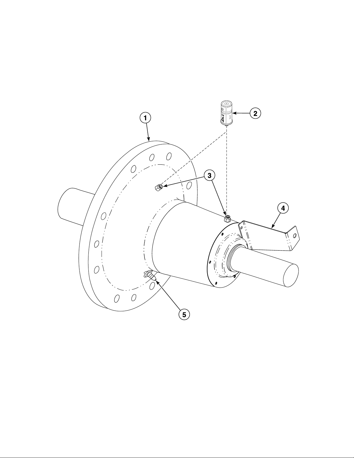
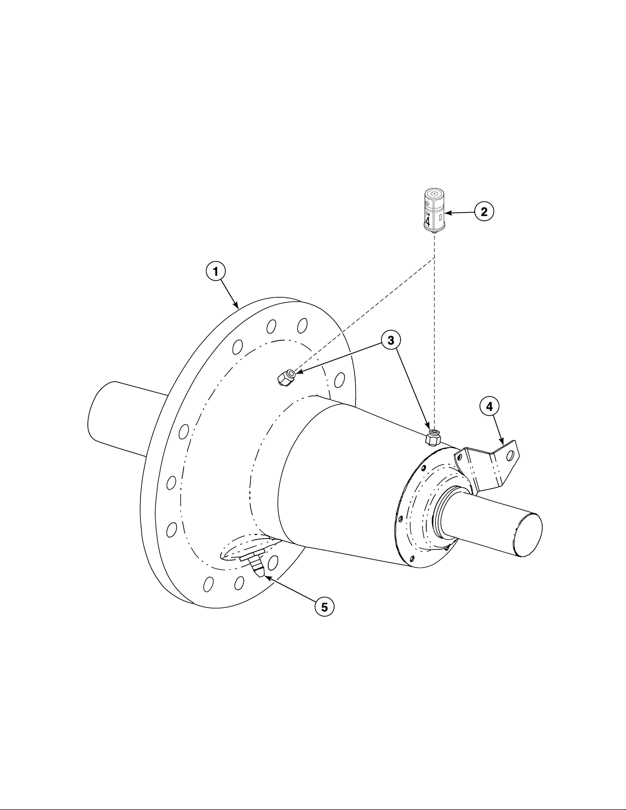
Bearing Housing Assembly (Drawing 5 of 6)
REF PART NO. DESCRIPTION COMMENTS
NA 1390P Bearing Housing Puller Kit Purchase
NA 1390-1 Bearing Housing Puller Kit Rental; Requires C002023 Hardware Kit
NA C002023 Hardware Kit
NA C001020 Screw 8 required; Bearing housing to frame
NA C001021 Washer 8 required; Bearing housing to frame
NA F430929 Screw 6 required for rear seal plate to bearing housing; 6
required for front seal plates to bearing housing
NA C000571 Washer 6 required for rear seal plate to bearing housing; 6
required for front seal plates to bearing housing
NA C002637P Proximity Switch Assembly 1 required; Proximity switch on bearing housing
NA C000552 Hose 1 required; 26 inch; Weep hole fitting to drain line fitting
NA C000628P Tubing 2 required; 33 inch; Lube fittings to bearing housing
NA 36801 Hose Clamp 1 required; Bearing weep hole “TEE”
1 C000673P Bearing Housing Assembly Standard seals
1 C001946 Bearing Housing Assembly Viton seals
2 212/00022/00 Lubricator
3 J1408004 Connector 2 required
4 C000969 Proximity Mounting Bracket
5 C001649 Reducing Connector
C002923 23
© Copyright, Alliance Laundry Systems LLC – DO NOT COPY or TRANSMIT
Page 26
Bearing Housing Assembly (Drawing 6 of 6)
PHM2727P_C002923
Models CPC125H, CP125PHN1, CP125PHN2, CP125PHQ1, CP125PHQ2, CP140PMN1, CP140PMQ1,
IPH125H, IPH570, IP125PHN1, IP125PHN2, IP125PHQ1, IP125PHQ2, IP140PMN1, IP140PMQ1,
JP125PHN1, JP125PHN2 and JP140PMQ1
24 C002923
© Copyright, Alliance Laundry Systems LLC – DO NOT COPY or TRANSMIT
Page 27

Bearing Housing Assembly (Drawing 6 of 6)
REF PART NO. DESCRIPTION COMMENTS
NA 1390P Bearing Housing Puller Kit Purchase
NA 1390-1 Bearing Housing Puller Kit Rental; Requires C002023 Hardware Kit
NA C002023 Hardware Kit
NA C000554 Screw 8 required; Bearing housing to frame
NA C000555 Washer 8 required; Bearing housing to frame
NA F430929 Screw 6 required for rear seal plate to bearing housing; 6
required for front seal plates to bearing housing
NA C000571 Washer 6 required for rear seal plate to bearing housing; 6
required for front seal plates to bearing housing
NA C002637P Proximity Switch Assembly 1 required; Proximity switch on bearing housing
NA C000552 Hose 1 required; 26 inch; Weep hole fitting to drain line fitting
NA C000628P Tubing 2 required; 33 inch; Lube fittings to bearing housing
NA C003007 Triple Lip Seal
NA 36801 Hose Clamp 1 required; Bearing weep hole “TEE”
1 C000154P Bearing Housing Assembly Standard seals
1 C001946 Bearing Housing Assembly Viton seals
2 212/00022/00 Lubricator
3 J1408004 Connector 2 required
4 C000658 Mounting Bracket
5 C001649 Reducing Connector
C002923 25
© Copyright, Alliance Laundry Systems LLC – DO NOT COPY or TRANSMIT
Page 28
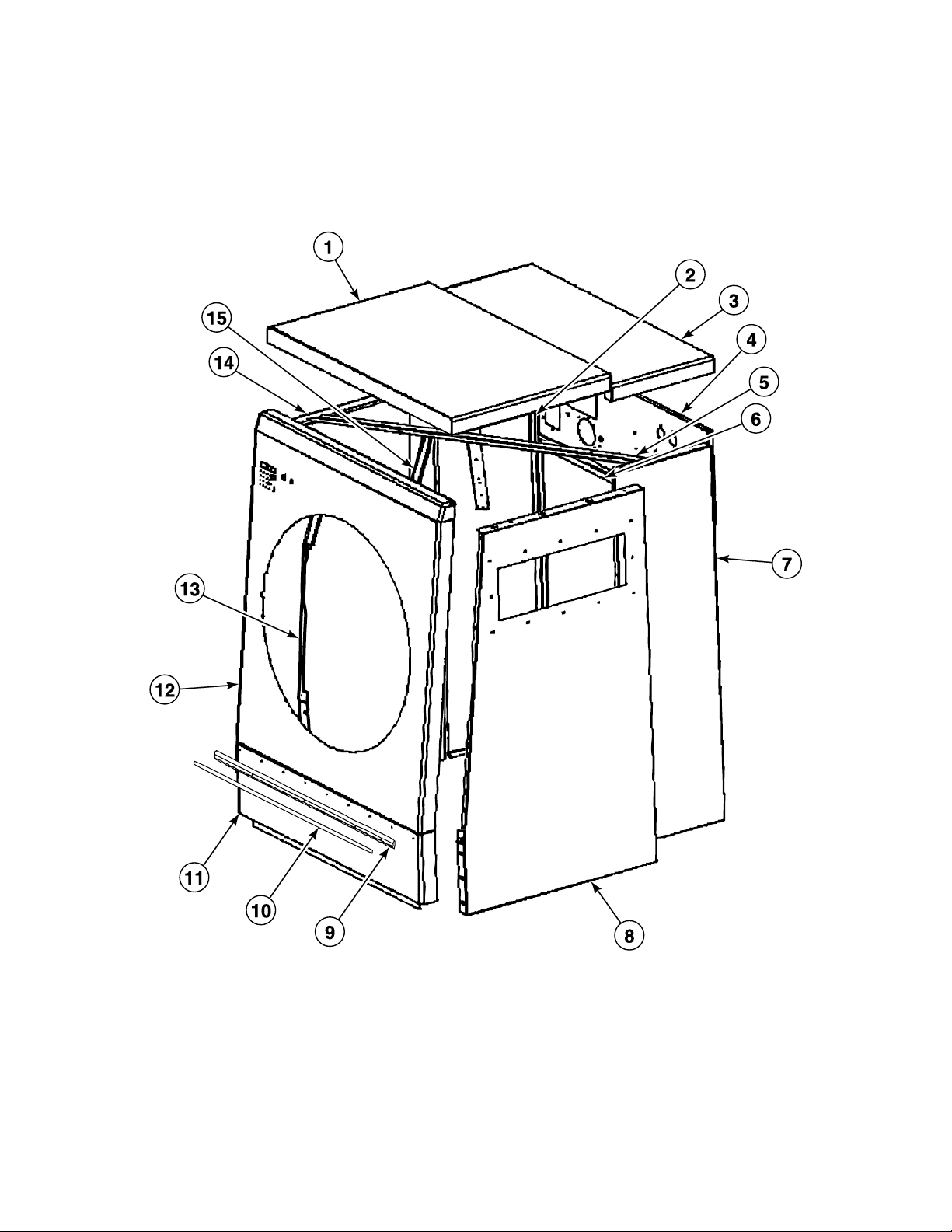
Cabinet Assembly (Drawing 1 of 4)
PHM2850P_C002923
Models CPC140H, CPC140M, IPH140H, IPH140M and IPH640
Models Through 3/23/04
26 C002923
© Copyright, Alliance Laundry Systems LLC – DO NOT COPY or TRANSMIT
Page 29

Cabinet Assembly (Drawing 1 of 4)
REF PART NO. DESCRIPTION COMMENTS
NA C000539 Grease Connector Box
NA C000567 Screw 2 required for grease box to valve panel; 6 required for valve
panel to side panel; 2 required for top panel to valve panel;
12 required for front panel to side panel; 2 required for lower
front panel to frame; 6 required for side panel to frame; 4
required for rear cover to side panel; 4 or 5 required for front
electrical mounting bracket to side panel
NA F431024 Nut 2 required for grease box to valve panel; 6 required for valve
panel to side panel; 4 required for front panel to side panel; 4
or 5 required for front electrical mounting bracket to side
panel
NA N/A Nut 2 required for top panel to valve panel; 2 required for lower
front panel to frame; 6 required for side panel to frame; 2
required for rear electrical cover to valve panel
NA C000571 Washer 2 required for top panel to valve panel; 2 required for lower
front panel to frame; 6 required for side panel to frame; 4
required for rear cover to side panel
NA C000585 Washer 2 required for lower front panel to frame; 6 required for side
panel to frame
NA F430929 Screw 2 required for rear electrical cover to valve panel; 1 required
for inlet power cover to valve panel
NA F430910 Screw 6 required for rub rails to lower front panel
NA C000568 Nut 6 required for rub rails to lower front panel
1 C002986 Front Top Panel Assembly
2 C002963 Side Panel Assembly
3 C000817 Rear Top Panel
4 C002983 Valve Panel Assembly
5 C000876 Top Brace 2 required
6 C000818 Rear Panel
7 C002962 Side Panel Assembly
8 C002717 Side Panel and Stiffener Assembly
9 C001014 Rub Rail Vinyl
10 C001015 Insert Rail
11 C000819 Lower Front Panel
12 C002973 Front Panel Assembly
13 C002718 Side Panel and Stiffener Assembly
14 C000875 Control Box Cover
15 C000874 Control Mounting Bracket 2 required
N/A = Part no longer available
C002923 27
© Copyright, Alliance Laundry Systems LLC – DO NOT COPY or TRANSMIT
Page 30
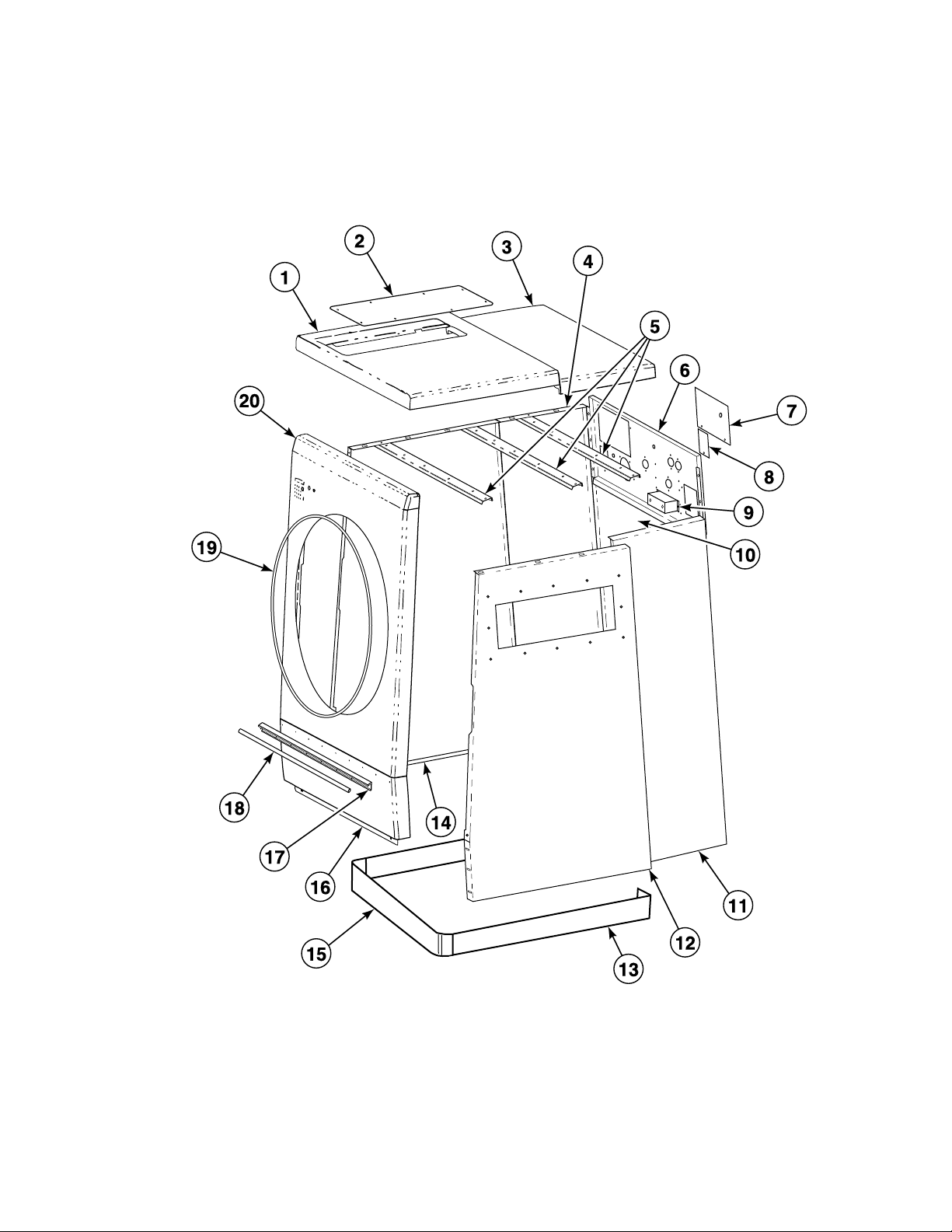
Cabinet Assembly (Drawing 2 of 4)
PHM2891P_C002923
Models CPC140H, CPC140M, IPH140H, IPH140M and IPH640
Models Starting 3/23/04 and Continuing Through 7/1/06
28 C002923
© Copyright, Alliance Laundry Systems LLC – DO NOT COPY or TRANSMIT
Page 31

Cabinet Assembly (Drawing 2 of 4)
REF PART NO. DESCRIPTION COMMENTS
NA C000567 Screw 6 required for valve panel to side panel; 2 required for top
panel to valve panel; 12 required for front panel to side panel;
2 required for lower front panel to frame; 6 required for side
panel to frame; 4 required for rear cover to side panel; 4 or 5
required for front electrical mounting bracket to side panel
NA F431024 Nut 6 required for valve panel to side panel; 4 required for front
panel to side panel; 4 or 5 required for front electrical
mounting bracket to side panel
NA N/A Nut 2 required for top panel to valve panel; 2 required for lower
front panel to frame; 6 required for side panel to frame; 2
required for rear electrical cover to valve panel
NA C000571 Washer 2 required for top panel to valve panel; 2 required for lower
front panel to frame; 6 required for side panel to frame; 4
required for rear cover to side panel
NA C000585 Washer 2 required for lower front panel to frame; 6 required for side
panel to frame
NA F430929 Screw 2 required for rear electrical cover to valve panel; 1 required
for inlet power cover to valve panel
NA F430910 Screw 6 required for rub rails to lower front panel
NA C000568 Nut 6 required for rub rails to lower front panel
1 C002986 Front Top Panel Assembly
2 C002017 Top Panel Access Cover
3 C000817 Rear Top Panel
4 C002963 Side Panel Assembly
5 C002018 Cabinet Stiffener 3 required
6 C000816 Valve Panel
7 C000173 Rear Electrical Enclosure Cover
8 N/A Inlet Power Cover
9 C000539 Grease Connector Box
10 C000818 Rear Panel
11 C002962 Side Panel Assembly
12 C002717 Side Panel and Stiffener Assembly
13 N/A Side Skirt Panel 2 required
14 C002718 Side Panel and Stiffener Assembly
15 C000316 Front Skirt Panel
16 C000819 Lower Front Panel
17 C001014 Rub Rail Vinyl
18 C001015 Insert Rail
19 C000629 Trim Gasket
20 C002973 Front Panel Assembly
N/A = Part no longer available
C002923 29
© Copyright, Alliance Laundry Systems LLC – DO NOT COPY or TRANSMIT
Page 32

Cabinet Assembly (Drawing 3 of 4)
PHM2890P_C002923
Models Starting 7/1/06
30 C002923
© Copyright, Alliance Laundry Systems LLC – DO NOT COPY or TRANSMIT
Page 33

Cabinet Assembly (Drawing 3 of 4)
REF PART NO. DESCRIPTION COMMENTS
NA C000567 Screw 2 required for top panel to valve panel; 12 required for front
panel to side panel; 2 required for lower front panel to frame; 4
or 5 required for front electrical mounting bracket to side panel
NA F431024 Nut 4 required for front panel to side panel; 4 or 5 required for front
electrical mounting bracket to side panel
NA N/A Nut 2 required for top panel to valve panel; 2 required for lower
front panel to frame
NA C000571 Washer 2 required for top panel to valve panel; 2 required for lower
front panel to frame
NA C000585 Washer 2 required for lower front panel to frame
NA F430910 Screw 6 required for rub rails to lower front panel
NA C000568 Nut 6 required for rub rails to lower front panel
1 C002986 Front Top Panel Assembly
2 C002017 Top Panel Access Cover
3 C000817 Rear Top Panel Models CPC140H, CPC140M, CP140PHN1, CP140PHQ1,
CP140PMN1, CP140PMQ1, IPH140H, IPH140M, IPH640,
IP140PHN1, IP140PHQ1, IP140PMN1, IP140PMQ1,
JP140PHN1, JP140PHQ1 and JP140PMQ1
3 C002298 Rear Top Panel Models CPC125H, CP125PHN1, CP125PHN2, CP125PHQ1,
CP125PHQ2, IPH125H, IPH570, IP125PHN1, IP125PHN2,
IP125PHQ1, IP125PHQ2, JP125PHN1 and JP125PHN2
4 N/A Side Skirt Panel
5 C000316 Front Skirt Panel
6 C000819 Lower Front Panel Models CPC140H, CPC140M, CP140PHN1, CP140PHQ1,
CP140PMN1, CP140PMQ1, IPH140H, IPH140M, IPH640,
IP140PHN1, IP140PHQ1, IP140PMN1, IP140PMQ1,
JP140PHN1, JP140PHQ1 and JP140PMQ1; Models through
6/30/09
6 C002912 Lower Front Panel Models CPC125H, CP125PHN1, CP125PHQ1, IPH125H,
IPH570, IP125PHN1, IP125PHQ1 and JP125PHN1; Models
through 6/30/09
6 C003081 Lower Front Panel Models starting 7/1/09
7 C001014 Rub Rail Vinyl
8 C001015 Insert Rail
9 C000629 Trim Gasket
10 C002972 Front Panel Assembly Models CPC125H, CP125PHN1, CP125PHQ1, IPH125H,
IPH570, IP125PHN1, IP125PHQ1 and JP125PHN1
10 C002973 Front Panel Assembly Models CPC140H, CPC140M, CP140PHN1, CP140PHQ1,
CP140PMN1, CP140PMQ1, IPH140H, IPH140M, IPH640,
IP140PHN1, IP140PHQ1, IP140PMN1, IP140PMQ1,
JP140PHN1, JP140PHQ1 and JP140PMQ1
N/A = Part no longer available
C002923 31
© Copyright, Alliance Laundry Systems LLC – DO NOT COPY or TRANSMIT
Page 34

Cabinet Assembly (Drawing 4 of 4)
PHM2890PA_C002923
Models Starting 7/1/06
32 C002923
© Copyright, Alliance Laundry Systems LLC – DO NOT COPY or TRANSMIT
Page 35

Cabinet Assembly (Drawing 4 of 4)
REF PART NO. DESCRIPTION COMMENTS
NA C000567 Screw 6 required for valve panel to side panel; 2 required for top
panel to valve panel; 12 required for front panel to side panel;
6 required for side panel to frame; 4 required for rear cover to
side panel; 4 or 5 required for front electrical mounting bracket
to side panel
NA F431024 Nut 6 required for valve panel to side panel; 4 required for front
panel to side panel; 4 or 5 required for front electrical mounting
bracket to side panel
NA N/A Nut 2 required for top panel to valve panel; 6 required for side
panel to frame; 2 required for rear electrical cover to valve
panel
NA C000571 Washer 2 required for top panel to valve panel; 6 required for side
panel to frame; 4 required for rear cover to side panel
NA C000585 Washer 6 required for side panel to frame
NA F430929 Screw 2 required for rear electrical cover to valve panel; 1 required
for inlet power cover to valve panel
1 C002018 Cabinet Stiffener 3 required
2 C002524 Drive Box Assembly Models CPC125H, CP125PHN1, CP125PHN2, CP125PHQ1,
CP125PHQ2, IPH125H, IPH570, IP125PHN1, IP125PHN2,
IP125PHQ1, IP125PHQ2, JP125PHN1 and JP125PHN2
3 C002983 Valve Panel Assembly
4 C002527 Drive and Power Enclosure Cover
5 C000539 Grease Connector Box
6 C000818 Rear Panel
7 C002960 Left Rear Side Panel Assembly Models CPC125H, CP125PHN1, CP125PHN2, CP125PHQ1,
CP125PHQ2, IPH125H, IPH570, IP125PHN1, IP125PHN2,
IP125PHQ1, IP125PHQ2, JP125PHN1 and JP125PHN2
7 C002962 Side Panel Assembly Left rear; Models CPC140H, CPC140M, CP140PHN1,
CP140PHQ1, CP140PMN1, CP140PMQ1, IPH140H,
IPH140M, IPH640, IP140PHN1, IP140PHQ1, IP140PMN1,
IP140PMQ1, JP140PHN1, JP140PHQ1 and JP140PMQ1
8 C002717 Side Panel and Stiffener Assembly
9 C002718 Side Panel and Stiffener Assembly
10 C002961 Right Rear Side Panel Assembly Models CPC125H, CP125PHN1, CP125PHN2, CP125PHQ1,
CP125PHQ2, IPH125H, IPH570, IP125PHN1, IP125PHN2,
IP125PHQ1, IP125PHQ2, JP125PHN1 and JP125PHN2
10 C002963 Side Panel Assembly Right rear; Models CPC140H, CPC140M, CP140PHN1,
CP140PHQ1, CP140PMN1, CP140PMQ1, IPH140H,
IPH140M, IPH640, IP140PHN1, IP140PHQ1, IP140PMN1,
IP140PMQ1, JP140PHN1, JP140PHQ1 and JP140PMQ1
N/A = Part no longer available
C002923 33
© Copyright, Alliance Laundry Systems LLC – DO NOT COPY or TRANSMIT
Page 36

Cylinder Assembly (Drawing 1 of 2)
PHM2882P_C002923
Models CPC140H, CPC140M, IPH140H, IPH140M and IPH640
Models Through 3/23/04
34 C002923
© Copyright, Alliance Laundry Systems LLC – DO NOT COPY or TRANSMIT
Page 37

Cylinder Assembly (Drawing 1 of 2)
REF PART NO. DESCRIPTION COMMENTS
1 C000785P Cylinder Assembly Kit Models CPC140H and IPH140H
1 C000883P Cylinder Assembly Kit Models CPC140M, IPH140M and IPH640
2 N/A Washer
N/A = Part no longer available
C002923 35
© Copyright, Alliance Laundry Systems LLC – DO NOT COPY or TRANSMIT
Page 38

Cylinder Assembly (Drawing 2 of 2)
PHM2800P_C002923
Models Starting 3/23/04
36 C002923
© Copyright, Alliance Laundry Systems LLC – DO NOT COPY or TRANSMIT
Page 39

Cylinder Assembly (Drawing 2 of 2)
REF PART NO. DESCRIPTION COMMENTS
1 C001239 Washer
2 C001238 Cylinder Bolt Shroud
3 C001093 Screw Models CPC140H and IPH140H starting 3/23/04 through
7/1/06; Models CPC125H, CPC140M, CP125PHN1,
CP125PHN2, CP125PHQ1, CP125PHQ2, CP140PMN1,
CP140PMQ1, IPH125H, IPH140M, IPH570, IPH640,
IP125PHN1, IP125PHN2, IP125PHQ1, IP125PHQ2,
IP140PMN1, IP140PMQ1, JP125PHN1, JP125PHN2
and JP140PMQ1
3 C001294 Screw Models CPC140H, CP140PHN1, CP140PHQ1,
IPH140H, IP140PHN1, IP140PHQ1, JP140PHN1 and
JP140PHQ1 starting 7/1/06
4 C002307P Cylinder Assembly Kit Models CPC125H, CP125PHN1, CP125PHN2,
CP125PHQ1, CP125PHQ2, IPH125H, IPH570,
IP125PHN1, IP125PHN2, IP125PHQ1, IP125PHQ2,
JP125PHN1 and JP125PHN2
4 C000785P Cylinder Assembly Kit Models CPC140H, CP140PHN1, CP140PHQ1,
IPH140H, IP140PHN1, IP140PHQ1, JP140PHN1 and
JP140PHQ1
4 C000883P Cylinder Assembly Kit Models CPC140M, CP140PMN1, CP140PMQ1,
IPH140M, IPH640, IP140PMN1, IP140PMQ1 and
JP140PMQ1
C002923 37
© Copyright, Alliance Laundry Systems LLC – DO NOT COPY or TRANSMIT
Page 40

Single Cup Dispenser Assembly
PHM2732P_C002923
38 C002923
© Copyright, Alliance Laundry Systems LLC – DO NOT COPY or TRANSMIT
Page 41

Single Cup Dispenser Assembly
REF PART NO. DESCRIPTION COMMENTS
NA C001148 Screw Models starting 3/23/04; 4 required for hinges to cover; 4
required for hinges to control panel
NA F430920 Screw Models CPC140H, CPC140M, CP140PHN1,
CP140PHQ1, CP140PMN1, CP140PMQ1, IPH140H,
IPH140M, IPH640, IP140PHN1, IP140PHQ1,
IP140PMN1, IP140PMQ1, JP140PHQ1 and
JP140PMQ1; 4 required for hinges to cover for models
through 3/23/04; 4 required for hinges to control panel for
models through 3/23/04; 2 required for dispenser cover
to handle for models starting 3/23/04
NA F430909 Screw 2 required for dispenser cover to handle; Models through
3/23/04
NA F430925 Screw 2 required for dispenser to control panel for all models;
12 required for side dispenser to side panel for 125 and
570 models
NA N/A Nut 2 required for dispenser to control panel
NA C000552 Hose Flush hose for supply dispenser; Models CPC140H,
CPC140M, CP140PHN1, CP140PHQ1, CP140PMN1,
CP140PMQ1, IPH140H, IPH140M, IPH640, IP140PHN1,
IP140PHQ1, IP140PMN1, IP140PMQ1, JP140PHN1,
JP140PHQ1 and JP140PMQ1
NA C000628P Tubing Flush hose for supply dispenser; Models CPC125H,
CP125PHN1, CP125PHN2, CP125PHQ1, CP125PHQ2,
IPH125H, IPH570, IP125PHN1, IP125PHN2,
IP125PHQ1, IP125PHQ2, JP125PHN1 and JP125PHN2
NA F200201 Hose Clamp 2 required for dispenser hose
1 C000853 Single Side Dispenser Assembly Models through 3/23/04
1 C001582 Single Side Dispenser Assembly Models starting 3/23/04
2 N/A Hinge 2 required; 2-part; Models through 3/23/04
2 C001787 Hinge 2 required; 2-part; Models starting 3/23/04
3 C000073 Supply Dispenser Nozzle
4 C000646 Supply Cup
5 C000855 Single Side Dispenser Door
6 C001788 Dispenser Door Handle
N/A = Part no longer available
C002923 39
© Copyright, Alliance Laundry Systems LLC – DO NOT COPY or TRANSMIT
Page 42

5 Cup Dispenser Assembly
PHM2733P_C002923
40 C002923
© Copyright, Alliance Laundry Systems LLC – DO NOT COPY or TRANSMIT
Page 43

5 Cup Dispenser Assembly
REF PART NO. DESCRIPTION COMMENTS
NA C001148 Screw Models starting 3/23/04; 4 required for hinges to cover; 4
required for hinges to control panel
NA F430920 Screw Models CPC140H, CPC140M, CP140PHN1,
CP140PHQ1, CP140PMN1, CP140PMQ1, IPH140H,
IPH140M, IPH640, IP140PHN1, IP140PHQ1,
IP140PMN1, IP140PMQ1, JP140PHN1, JP140PHQ1
and JP140PMQ1; 4 required for hinges to cover for
models through 3/23/04; 4 required for hinges to control
panel for models through 3/23/04; 2 required for
dispenser cover to handle for models starting 3/23/04
NA F430909 Screw 2 required for dispenser cover to handle; Models
CPC140H, CPC140M, CP140PHN1, CP140PHQ1,
CP140PMN1, CP140PMQ1, IPH140H, IPH140M,
IPH640, IP140PHN1, IP140PHQ1, IP140PMN1,
IP140PMQ1, JP140PHQ1 and JP140PMQ1 through
3/23/04
NA F430925 Screw 2 required for dispenser to control panel for all models;
12 required for side dispenser to side panel for 125 and
570 models
NA N/A Nut 2 required for dispenser to control panel
NA 36801 Hose Clamp 7 required for supply dispenser
NA C001004 Spring Hose Clamp 5 required for supply dispenser
NA F200201 Hose Clamp 2 required for dispenser hose
NA C000552 Hose Flush hose; Models CPC140H, CPC140M, CP140PHN1,
CP140PHQ1, CP140PMN1, CP140PMQ1, IPH140H,
IPH140M, IPH640, IP140PHN1, IP140PHQ1,
IP140PMN1, IP140PMQ1, JP140PHN1, JP140PHQ1
and JP140PMQ1 use 22 inches for supply cup 1, 28
inches for supply cup 2, 33 inches for supply cup 3, 38
inches for supply cup 4, 42 inches for supply cup 5;
Models CPC125H, CP125PHN1, CP125PHN2,
CP125PHQ1, CP125PHQ2, IPH125H, IPH570,
IP125PHN1, IP125PHN2, IP125PHQ1, IP125PHQ2,
JP125PHN1 and JP125PHN2 use 16 inches for supply
cup 1, 20 inches for supply cup 2, 26 inches for supply
cup 3, 32 inches for supply cup 4, 35 inches for supply
cup 5
1 C001583 Side Dispenser Assembly Models starting 3/23/04
1 C000648 Side Dispenser Assembly Models through 3/23/04
2 C001788 Dispenser Door Handle
3 C001787 Hinge 2 required; 2-part; Models starting 3/24/04
3 N/A Hinge 2 required; 2-part; Models through 3/24/04
4 C000073 Supply Dispenser Nozzle 5 required
5 C000647 Supply Cup 2 required
6 C000646 Supply Cup 3 required
7 C000642 Side Dispenser Door
N/A = Part no longer available
C002923 41
© Copyright, Alliance Laundry Systems LLC – DO NOT COPY or TRANSMIT
Page 44

Door Assembly - Models through 2/9/09
PHM2903P_C002923
42 C002923
© Copyright, Alliance Laundry Systems LLC – DO NOT COPY or TRANSMIT
Page 45

Door Assembly - Models through 2/9/09
REF PART NO. DESCRIPTION COMMENTS
NA C000559 Bolt 8 required for door hinge block to shell front
NA C000574 Nut 8 required for door hinge block to shell front
NA 803017 Nut 2 required for door hinge block to hinge
NA C000561 Bolt 5 required for door hinge to door; 4 required for door
handle hinge to door for models through 3/23/04; 3
required for door handle hinge to door for models
starting 3/24/04
NA C000560 Nut 5 required for door hinge to door; 4 required for door
handle hinge to door
NA F8549401 Nut 8 required for door glass retainer to door
NA C000601 Stud 8 required for door glass retainer to door
NA F431024 Nut 1 required for door handle to door handle hinge
NA C001236 Nut 1 required for door handle to door handle bushing
NA C001546 Door Bumper 2 required for door; Models starting 3/23/04
NA C001032 Screw 2 required for door bumper; Models starting 3/23/04
1 C000180 Bolt
2 C000181 Door Handle Bushing
3 C000749 Door Glass
4 C000710 Door
5 253/00162/02 Door Seal
6 F8513501 Shell Front Gasket Kit 7 feet required
7 C000750 Door Glass Gasket
8 F8549301 Bolt 2 required
9 C000175 Hinge Block 2 required
10 C000176 Door Hinge Bushing 2 required
11 C000177 Washer 2 required
12 C000752 Door Hinge
13 C000751MD Door Glass Retainer
14 C000028P Door Handle Models through 3/23/04
14 C001679P Door Handle Models starting 3/24/04
15 C000470 Door Handle Hinge Weldment
16 C001785 Bolt
17 C000192 Door Handle Spring Bushing
18 C001786 Door Handle Torsion Spring
19 C000748P Door Assembly
C002923 43
© Copyright, Alliance Laundry Systems LLC – DO NOT COPY or TRANSMIT
Page 46

Door Assembly - Models starting 2/10/09
PHM3095P_C002923
44 C002923
© Copyright, Alliance Laundry Systems LLC – DO NOT COPY or TRANSMIT
Page 47

Door Assembly - Models starting 2/10/09
REF PART NO. DESCRIPTION COMMENTS
NA C000559 Bolt 8 required for door hinge block to shell front
NA C000574 Nut 8 required for door hinge block to shell front
NA 803017 Nut 2 required for door hinge block to hinge
NA C000561 Bolt 5 required for door hinge to door; 3 required for door
handle hinge to door
NA C000560 Nut 5 required for door hinge to door; 4 required for door
handle hinge to door
NA F8549401 Nut 16 required for door glass retainer to door
NA C000601 Stud 16 required for door glass retainer to door
NA F431024 Nut 1 required for door handle to door handle hinge
NA C001236 Nut 1 required for door handle to door handle bushing
NA C001546 Door Bumper 2 required for door
NA C001032 Screw 2 required for door bumper
1 C000181 Door Handle Bushing
2 C000180 Bolt
3 C000749 Door Glass
4 C000710 Door
5 253/00162/02 Door Seal
6 F8513501 Shell Front Gasket Kit 7 feet required
7 C000750 Door Glass Gasket
8 F8549301 Bolt 2 required
9 C000175 Hinge Block 2 required
10 C000176 Door Hinge Bushing 2 required
11 C000177 Washer 2 required
12 C000752 Door Hinge
13 C000751MD Door Glass Retainer
14 C001679P Door Handle
15 C001785 Bolt
16 C000192 Door Handle Spring Bushing
17 C001786 Door Handle Torsion Spring
18 C000470 Door Handle Hinge Weldment
19 F431223 Pop Rivet
20 F8390801 Magnet
21 C002994 Door Magnet Mounting Bracket
22 C000748P Door Assembly Includes items 1-21
C002923 45
© Copyright, Alliance Laundry Systems LLC – DO NOT COPY or TRANSMIT
Page 48

Door Lock
PHM2777P_C002923
Models Through Serial No. 0902007001
46 C002923
© Copyright, Alliance Laundry Systems LLC – DO NOT COPY or TRANSMIT
Page 49

Door Lock
REF PART NO. DESCRIPTION COMMENTS
NA 81398 Screw 4 required for door lock cover to solenoid bracket;
Models starting 3/23/04
NA C000430 Bolt 4 required for door lock cover to door lock plate for
models through 3/23/04; 4 required for door solenoid
bracket to door lock plate for models starting 3/23/04
NA C000614 Screw 2 required for door lock switch to door lock plate; 2
required for door lock switch to door lock solenoid
bracket
NA C000578 Nut 2 required for door lock switch to door lock plate; 2
required for door lock switch to door lock solenoid
bracket
NA C000561 Bolt 4 required for door lock to shell front
NA C000574 Nut 4 required for door lock to shell front
NA C000567 Screw 2 required for door latch to door lock plate
NA C000571 Washer 2 required for door latch to door lock plate; Models
starting 3/23/04
NA C000572 Screw 2 required for door lock solenoid to bracket
NA C000612 Screw 3 required for door lock catch to door lock plate
NA C000613 Screw 2 required for door solenoid bracket to door lock plate;
Models through 3/23/04
NA C000576 Nut 2 required for door solenoid bracket to door lock plate
NA C000867P Door Lock Harness
NA C003291 Jump Wire
1 C000688 Door Lock Cover
2 C000431 Spring 2 required
3 C000684 Door Lock Plate
4 C000430 Bolt 4 required
5 C000278 Door Lock Microswitch
6 C000184P Door Lock Solenoid
7 C000185 Door Lock Catch
8 C000276 Door Lock Slide Spring
9 C000271 Door Lock Switch Slide
10 N/A Door Lock Latch Models through 3/23/04
10 C001244 Door Latch Models starting 3/23/04
11 C000687 Door Lock Spring Cover
12 C003022 Door Lock Solenoid Bracket
13 C001036M Door Lock Kit Includes items 1-12; Models through 7/14/11 MUST
order C002996M Door Lock Kit
13 C002996M Door Lock Kit
N/A = Part no longer available
C002923 47
© Copyright, Alliance Laundry Systems LLC – DO NOT COPY or TRANSMIT
Page 50

Door Lock Assembly with Magnetic Sensor
PHM3149P_C002923
Models Starting Serial No. 0902007002
48 C002923
© Copyright, Alliance Laundry Systems LLC – DO NOT COPY or TRANSMIT
Page 51

Door Lock Assembly with Magnetic Sensor
REF PART NO. DESCRIPTION COMMENTS
NA 81398 Screw 4 required for door lock cover to solenoid bracket;
Models starting 3/23/04
NA C000613 Screw 2 required for door solenoid bracket to door lock plate;
Models through 3/23/04
NA C000614 Screw 2 required for door lock switch to door lock plate; 2
required for door lock switch to door lock solenoid
bracket
NA C000578 Nut 2 required for door lock switch to door lock plate; 2
required for door lock switch to door lock solenoid
bracket
NA C000561 Bolt 4 required for door lock to shell front
NA C000574 Nut 4 required for door lock to shell front
NA C000567 Screw 2 required for door latch to door lock plate
NA C000571 Washer 2 required for door latch to door lock plate; Models
starting 3/23/04
NA C000572 Screw 2 required for door lock solenoid to bracket
NA C000612 Screw 3 required for door lock catch to door lock plate
NA C000430 Bolt 4 required for door solenoid bracket to door lock plate for
models starting 3/23/04; 4 required for door lock cover to
door lock plate for models through 3/23/04
NA C000576 Nut 2 required for door lock cover to door lock plate
NA C000867P Door Lock Harness
NA C003291 Jump Wire
1 C000688 Door Lock Cover
2 C000431 Spring
3 C000278 Door Lock Microswitch
4 C000430 Bolt
5 C002995 Magnetic Door Switch Bracket
6 C003000 Reed Switch Assembly
7 C000684 Door Lock Plate
8 J1111 905 Bl in d R i v e t
9 C000184P Door Lock Solenoid
10 C000271 Door Lock Switch Slide
11 C000276 Door Lock Slide Spring
12 C000185 Door Lock Catch
13 N/A Door Latch Models through 3/23/04
13 C001244 Door Latch Models starting 3/23/04
14 C000687 Door Lock Spring Cover
15 C003022 Door Lock Solenoid Bracket
16 B12351001 Door Lock Spring Models starting 12/13/10
17 F431215 Pop Rivet Models starting 12/13/10
18 C002996M Door Lock Kit Includes items 1-17
N/A = Part no longer available
C002923 49
© Copyright, Alliance Laundry Systems LLC – DO NOT COPY or TRANSMIT
Page 52

5 Cup Hot Plumbing Assembly
PHM2854P_C002923
Models CPC140H, CPC140M, IPH140H, IPH140M and IPH640
Models Through 7/1/06
50 C002923
© Copyright, Alliance Laundry Systems LLC – DO NOT COPY or TRANSMIT
Page 53

5 Cup Hot Plumbing Assembly
REF PART NO. DESCRIPTION COMMENTS
NA C000567 Screw 2 required for hot manifold to valve panel
NA F431024 Nut 2 required for hot manifold to valve panel
NA C001011 Hose 1 required; 43 inch; Hot water valve to vacuum breaker
NA C002612P Inlet Valve Harness
1 C000897 Hot Plumbing Assembly
2 C000899 Hose Barb
3 C000339P Water Valve Parker
4 C000894 Nipple 2 required
5 C000893 Street Elbow 2 required
6 C000900 Tee
7 C000892 Mounting Bracket
8 C000896 Nipple
9 C000895 Reducer
10 C000424 Adapter
11 C000716P Valve
11 G582P3 Diaphragm and Guide Kit
C002923 51
© Copyright, Alliance Laundry Systems LLC – DO NOT COPY or TRANSMIT
Page 54

1 Cup Hot Plumbing Assembly
PHM2855P_C002923
Models CPC140H, CPC140M, IPH140H, IPH140M and IPH640
Models Starting 3/23/04 and Continuing Through 7/1/06
52 C002923
© Copyright, Alliance Laundry Systems LLC – DO NOT COPY or TRANSMIT
Page 55

1 Cup Hot Plumbing Assembly
REF PART NO. DESCRIPTION COMMENTS
NA C001011 Hose 43 inch; Hot water valve to vacuum breaker
NA C000567 Screw 2 required for hot manifold to valve panel
NA F431024 Nut 2 required for hot manifold to valve panel
NA C002609P Inlet Valve Harness
1 C000893 Street Elbow 2 required
2 C000894 Nipple 2 required
3 C000895 Reducer
4 C000424 Adapter
5 C001665 Hot Plumbing Assembly
6 C000716P Valve
6 G582P3 Diaphragm and Guide Kit
7 C000339P Water Valve Parker
8 C000899 Hose Barb
9 C000900 Tee
10 C000892 Mounting Bracket
11 C000896 Nipple
C002923 53
© Copyright, Alliance Laundry Systems LLC – DO NOT COPY or TRANSMIT
Page 56

5 Cup Cold Plumbing Assembly (Drawing 1 of 3)
PHM2859P_C002923
Models CPC140H, CPC140M, IPH140H, IPH140M and IPH640
Models Through 7/1/06
54 C002923
© Copyright, Alliance Laundry Systems LLC – DO NOT COPY or TRANSMIT
Page 57

5 Cup Cold Plumbing Assembly (Drawing 1 of 3)
REF PART NO. DESCRIPTION COMMENTS
NA C001011 Hose 22 inch; Cold water valve to vacuum breaker
NA C000567 Screw 2 required for cold manifold to valve panel
NA F431024 Nut 2 required for cold manifold to valve panel
NA C002612P Inlet Valve Harness
1 C000898 5 Cup Cold Plumbing Assembly
2 C000899 Hose Barb
3 C000893 Street Elbow 1 required for models through 3/23/04; 2 required for
models starting 3/23/04
4 C000339P Water Valve Parker
4 F380992P Water Valve Repair Kit 1.25 inches
5 C000894 Nipple
6 C000900 Tee
7 C000892 Mounting Bracket
8 C000896 Nipple
9 C001005 Nipple
10 C000895 Reducer
11 C000424 Adapter
12 C000436P Water Valve
12 G582P3 Diaphragm and Guide Kit
C002923 55
© Copyright, Alliance Laundry Systems LLC – DO NOT COPY or TRANSMIT
Page 58

5 Cup Cold Plumbing Assembly (Drawing 2 of 3)
PHM2804P_C002923
Models CPC140H, CPC140M, CP140PHN1, CP140PHQ1, CP140PMN1, CP140PMQ1, IPH140H, IPH140M,
IPH640, IP140PHN1, IP140PHQ1, IP140PMN1, IP140PMQ1, JP140PHN1, JP140PHQ1 and JP140PMQ1
Models Starting 7/1/06
56 C002923
© Copyright, Alliance Laundry Systems LLC – DO NOT COPY or TRANSMIT
Page 59

5 Cup Cold Plumbing Assembly (Drawing 2 of 3)
REF PART NO. DESCRIPTION COMMENTS
NA C001011 Hose 22 inch; Cold water valve to vacuum breaker
NA C000567 Screw 2 required for cold manifold to valve panel
NA F431024 Nut 2 required for cold manifold to valve panel
NA C002612P Inlet Valve Harness
1 C002538 5 Cup Cold Plumbing Assembly
2 C000436P Water Valve 2 required
2 G582P3 Diaphragm and Guide Kit
3 C000424 Adapter 2 required
4 F420502 Street Elbow 2 required
5 F420403 Tee
6 F420107 Nipple
7 C002164 Mounting Flange Weldment
8 C002165 Reducing Tee
9 C000894 Nipple
10 C000339P Water Valve Parker
10 C001676P Water Valve Rebuild Kit 1.25 inches
11 C000899 Hose Barb
C002923 57
© Copyright, Alliance Laundry Systems LLC – DO NOT COPY or TRANSMIT
Page 60

5 Cup Cold Plumbing Assembly (Drawing 3 of 3)
PH M2856P_C 002923
Models CPC125H, CP125PHN1, CP125PHN2, CP125PHQ1, CP125PHQ2, IPH125H, IPH570, IP125PHN1,
IP125PHN2, IP125PHQ1, IP125PHQ2, JP125PHN1 and JP125PHN2
58 C002923
© Copyright, Alliance Laundry Systems LLC – DO NOT COPY or TRANSMIT
Page 61

5 Cup Cold Plumbing Assembly (Drawing 3 of 3)
REF PART NO. DESCRIPTION COMMENTS
NA F200128P Water Hose 16 inch; Cold water valve to vacuum breaker
NA C000567 Screw 2 required for cold manifold to valve panel
NA F431024 Nut 2 required for cold manifold to valve panel
NA C002612P Inlet Valve Harness
NA F8514701 Coil Use with F8322909 Valve
NA F8382301 DIN Valve Adapter Kit Use with F8322909 Valve
NA F8456202P Valve Transition Kit Use with F8322909 Valve
1 C002563 Cold Plumbing Assembly
2 C000424 Adapter 2 required
3 C000420 Coupling 2 required
4 F380986P DIN Coil 120 Volt
4 F380987P DIN Coil 240 Volt
5 C000410 Drain Bracket 2 required
6 F380991P Water Valve Repair Kit 3/4 inch; Use with F381700P Valve
6 F8322909P Valve Replaces F381700P Valve; Includes F8514701 Coil
7 F420502 Street Elbow 2 required
8 F420107 Nipple
9 C001366 Flange and Nipple Assembly
10 C002166 Cross
11 C000436P Water Valve 2 required
11 G582P3 Diaphragm and Guide Kit
12 F421951 Hose Barb
C002923 59
© Copyright, Alliance Laundry Systems LLC – DO NOT COPY or TRANSMIT
Page 62

Single Cup Cold Plumbing Assembly (Drawing 1 of 3)
PHM2853P_C002923
Models CPC140H, CPC140M, IPH140H, IPH140M and IPH640
Models Through 7/1/06
60 C002923
© Copyright, Alliance Laundry Systems LLC – DO NOT COPY or TRANSMIT
Page 63

Single Cup Cold Plumbing Assembly (Drawing 1 of 3)
REF PART NO. DESCRIPTION COMMENTS
NA C001011 Hose 22 inch; Cold water valve to vacuum breaker
NA C000567 Screw 2 required for cold manifold to valve panel
NA F431024 Nut 2 required for cold manifold to valve panel
NA C002609P Inlet Valve Harness
1 C001022 Single Cup Cold Plumbing Assembly
2 C000339P Water Valve
3 C000893 Street Elbow 3 required
4 C000892 Mounting Bracket
5 C000896 Nipple
6 C000899 Hose Barb
C002923 61
© Copyright, Alliance Laundry Systems LLC – DO NOT COPY or TRANSMIT
Page 64

Single Cup Cold Plumbing Assembly (Drawing 2 of 3)
PHM2803P_C002923
Models CPC140H, CPC140M, CP140PHN1, CP140PHQ1, CP140PMN1, CP140PMQ1, IPH140H, IPH140M,
IPH640, IP140PHN1, IP140PHQ1, IP140PMN1, IP140PMQ1, JP140PHN1, JP140PHQ1 and JP140PMQ1
Models Starting 7/1/06
62 C002923
© Copyright, Alliance Laundry Systems LLC – DO NOT COPY or TRANSMIT
Page 65

Single Cup Cold Plumbing Assembly (Drawing 2 of 3)
REF PART NO. DESCRIPTION COMMENTS
NA C001011 Hose 22 inch; Cold water valve to vacuum breaker
NA C000567 Screw 2 required for cold manifold to valve panel
NA F431024 Nut 2 required for cold manifold to valve panel
NA C002609P Inlet Valve Harness
1 C002537 Single Cup Cold Plumbing Assembly
2 C002164 Mounting Flange Weldment
3 C002165 Reducing Tee
4 C000894 Nipple
5 C000339P Water Valve Parker
6 C000899 Hose Barb
7 C000716P Valve
7 G582P3 Diaphragm and Guide Kit
8 C000424 Adapter
9 F420502 Street Elbow
C002923 63
© Copyright, Alliance Laundry Systems LLC – DO NOT COPY or TRANSMIT
Page 66

Single Cup Cold Plumbing Assembly (Drawing 3 of 3)
PH M2852P_C 002923
Models CPC125H, CP125PHN1, CP125PHN2, CP125PHQ1, CP125PHQ2, IPH125H, IPH570, IP125PHN1,
IP125PHN2, IP125PHQ1, IP125PHQ2, JP125PHN1 and JP125PHN2
64 C002923
© Copyright, Alliance Laundry Systems LLC – DO NOT COPY or TRANSMIT
Page 67

Single Cup Cold Plumbing Assembly (Drawing 3 of 3)
REF PART NO. DESCRIPTION COMMENTS
NA C000552 Hose 14 inch; Cold water valve to vacuum breaker
NA C000567 Screw 2 required for cold manifold to valve panel
NA F431024 Nut 2 required for cold manifold to valve panel
NA C002609P Inlet Valve Harness
NA F8514701 Coil Use with F8322909 Valve
NA F8382301 DIN Valve Adapter Kit Use with F8322909 Valve
NA F8456202P Valve Transition Kit Use with F8322909 Valve
1 C002564 Cold Plumbing Assembly
2 C000716P Valve
2 G582P3 Diaphragm and Guide Kit
3 C000424 Adapter
4 F420403 Tee
5 C001366 Flange and Nipple Assembly
6 F420502 Street Elbow 3 required
7 F420107 Nipple
8 F8322909P Valve Replaces F381700P Valve; Includes F8514701 Coil
9 F421951 Hose Barb
10 F380986P DIN Coil 120 Volt
10 F380987P DIN Coil 240 Volt
C002923 65
© Copyright, Alliance Laundry Systems LLC – DO NOT COPY or TRANSMIT
Page 68

Auxiliary Plumbing Assembly with Valve
PHM2889P_C002923
Models CPC140H, CPC140M, IPH140H, IPH140M and IPH640
Models Through 7/1/06
66 C002923
© Copyright, Alliance Laundry Systems LLC – DO NOT COPY or TRANSMIT
Page 69

Auxiliary Plumbing Assembly with Valve
REF PART NO. DESCRIPTION COMMENTS
NA C001011 Hose 37 inch; Auxiliary water valve to vacuum breaker
1 C000899 Hose Barb
2 C000339P Water Valve
3 C001144 Nipple
4 C001143 Coupling
5 C000892 Mounting Bracket
6 C000896 Nipple
7 C000893 Street Elbow
8 C001145 Auxiliary Plumbing Assembly
C002923 67
© Copyright, Alliance Laundry Systems LLC – DO NOT COPY or TRANSMIT
Page 70

Auxiliary Plumbing Assembly without Valve (Drawing 1 of 2)
PHM2888P_C002923
Models CPC140H, CPC140M, IPH140H, IPH140M and IPH640
Models Starting 3/23/04 Through 7/1/06
68 C002923
© Copyright, Alliance Laundry Systems LLC – DO NOT COPY or TRANSMIT
Page 71

Auxiliary Plumbing Assembly without Valve (Drawing 1 of 2)
REF PART NO. DESCRIPTION COMMENTS
NA C001011 Hose 37 inch; Auxiliary water valve to vacuum breaker
1 C001273 Auxiliary Plumbing Assembly
2 C000899 Hose Barb
3 C000893 Street Elbow
4 C001143 Coupling
5 C000896 Nipple
6 C000892 Mounting Bracket
C002923 69
© Copyright, Alliance Laundry Systems LLC – DO NOT COPY or TRANSMIT
Page 72

Auxiliary Plumbing Assembly without Valve (Drawing 2 of 2)
PHM2805P_C002923
Models CPC140H, CPC140M, CP140PHN1, CP140PHQ1, CP140PMN1, CP140PMQ1, IPH140H, IPH140M, IPH640,
IP140PHN1, IP140PHQ1, IP140PMN1, IP140PMQ1, JP140PHN1, JP140PHQ1 and JP140PMQ1
Models Starting 7/1/06
70 C002923
© Copyright, Alliance Laundry Systems LLC – DO NOT COPY or TRANSMIT
Page 73

Auxiliary Plumbing Assembly without Valve (Drawing 2 of 2)
REF PART NO. DESCRIPTION COMMENTS
NA C001011 Hose 37 inch; Auxiliary water valve to vacuum breaker
1 C002397 Auxiliary Plumbing Assembly
2 C000899 Hose Barb
3 C001143 Coupling
4 C002164 Mounting Flange Weldment
C002923 71
© Copyright, Alliance Laundry Systems LLC – DO NOT COPY or TRANSMIT
Page 74

Hot and Auxiliary Plumbing Assembly with Valve (Drawing 1 of 2)
PHM2739P_C002923
Models CPC125H, CP125PHN1, CP125PHN2, CP125PHQ1, CP125PHQ2, IPH125H, IPH570, IP125PHN1,
IP125PHN2, IP125PHQ1, IP125PHQ2, JP125PHN1 and JP125PHN2
72 C002923
© Copyright, Alliance Laundry Systems LLC – DO NOT COPY or TRANSMIT
Page 75

Hot and Auxiliary Plumbing Assembly with Valve (Drawing 1 of 2)
REF PART NO. DESCRIPTION COMMENTS
NA C000552 Hose 21 inch; 1 cup; Hot water valve to vacuum breaker
NA F200128P Water Hose 21 inch; 5 cup; Hot water valve to vacuum breaker
NA C000567 Screw 2 required for hot manifold to valve panel
NA F431024 Nut 2 required for hot manifold to valve panel
NA F8514701 Coil Use with F8322909 Valve
NA F8382301 DIN Valve Adapter Kit Use with F8322909 Valve
NA F8456202P Valve Transition Kit Use with F8322909 Valve
1 C002565 Hot Plumbing Assembly
2 F8322909P Valve Replaces F381700P Valve; Includes F8514701 Coil
3 F421951 Hose Barb
4 F420502 Street Elbow
5 C001366 Flange and Nipple Assembly
C002923 73
© Copyright, Alliance Laundry Systems LLC – DO NOT COPY or TRANSMIT
Page 76

Hot and Auxiliary Plumbing Assembly with Valve (Drawing 2 of 2)
PHM2802P_C002923
Models CPC140H, CPC140M, CP140PHN1, CP140PHQ1, CP140PMN1, CP140PMQ1, IPH140H, IPH140M,
IPH640, IP140PHN1, IP140PHQ1, IP140PMN1, IP140PMQ1, JP140PHN1, JP140PHQ1 and JP140PMQ1
Models Starting 7/1/06
74 C002923
© Copyright, Alliance Laundry Systems LLC – DO NOT COPY or TRANSMIT
Page 77

Hot and Auxiliary Plumbing Assembly with Valve (Drawing 2 of 2)
REF PART NO. DESCRIPTION COMMENTS
NA C000567 Screw 2 required for hot manifold to valve panel
NA F431024 Nut 2 required for hot manifold to valve panel
NA C001011 Hose 43 inch; Hot water valve to vacuum breaker
1 C002539 Hot Plumbing Assembly
2 C000339P Water Valve
3 C002164 Mounting Flange Weldment
4 C000899 Hose Barb
C002923 75
© Copyright, Alliance Laundry Systems LLC – DO NOT COPY or TRANSMIT
Page 78

Steam Heat Assembly
PHM3094P_C002923
76 C002923
© Copyright, Alliance Laundry Systems LLC – DO NOT COPY or TRANSMIT
Page 79

Steam Heat Assembly
REF PART NO. DESCRIPTION COMMENTS
1 C001000 Steam Option Assembly
2 F421707 Street Elbow
3 F603132 Steam Injector Tube Assembly
4 C000978 Reducing Coupling
5 C000982 Steam Hose
6 C001003 Steam Hose Insulation
7 C001587 Steam Hose Adapter
8 C002748P Steam Cord Assembly
9 C000981 Steam Valve Mounting Bracket
10 C002898 Steam Inlet Weldment
11 F8322904P Steam Valve
12 F421323 Nipple
C002923 77
© Copyright, Alliance Laundry Systems LLC – DO NOT COPY or TRANSMIT
Page 80

Shell Assembly (Drawing 1 of 2)
PH M3206P_C 002923
Models CPC140H, CPC140M, CP140PHN1, CP140PHQ1, CP140PMN1, CP140PMQ1, IPH140H, IPH140M,
IPH640, IP140PHN1, IP140PHQ1, IP140PMN1, IP140PMQ1, JP140PHN1, JP140PHQ1 and JP140PMQ1
78 C002923
© Copyright, Alliance Laundry Systems LLC – DO NOT COPY or TRANSMIT
Page 81

Shell Assembly (Drawing 1 of 2)
REF PART NO. DESCRIPTION COMMENTS
NA C001856 Screw 2 required; Holds bands together; Models through 3/23/04
NA C001907 Screw 2 required; Holds bands together; Models starting 3/23/04
NA F431024 Nut 2 required; Holds bands together; Models through 3/23/04
NA C000560 Nut 2 required; Holds bands together; Models starting 3/23/04
NA C000590 Washer As required; Holds bands together; Models through 3/23/04
NA J1001270 Washer As required; Holds bands together; Models starting 3/23/04
NA C000273 Bolt 4 required for shell support bracket to frame; 2 required for
shell support bracket to shell
NA C000611 Nut 4 required for shell support bracket to frame; 2 required for
shell support bracket to shell
NA C000583 Washer 8 required for shell support bracket to frame; 4 required for
shell support bracket to shell
NA C000561 Bolt 8 required for shell back to frame; Models through 3/23/04
NA C001032 Screw 8 required for shell back to frame; Models starting 3/23/04
NA C000599 Vacuum Breaker Hose Models through 3/23/04, 1 required for brass air trap tube to
sensor; Models starting 3/23/04, 1 required for air trap to
water level switch
NA C000654 Air Trap Tube Elbow 1 required for shell back plate; Models through 3/23/04
NA C000662 Air Trap Tube 1 required for air trap tube; Models through 3/23/04
1 C002978 Shell Front Assembly Models through 12/1/09
1 C002943 Shell Front Assembly Models starting 12/2/09
2 C002730 Shell Band Weldment Short
3 N/A Shell Front Gasket Models through 3/23/04
3 C001876P Shell Front Gasket Models starting 3/23/04
4 C000772 Shell Assembly
5 C000781 Plug
6 F601216 Shell Gasket Shield
7 N/A Shell Front Band Models through 3/23/04
7 C001887 Shell Band Weldment Models starting 3/23/04
N/A = Part no longer available
C002923 79
© Copyright, Alliance Laundry Systems LLC – DO NOT COPY or TRANSMIT
Page 82

Shell Assembly (Drawing 2 of 2)
PH M3206P_C 002923
Models CPC125H, CP125PHN1, CP125PHN2, CP125PHQ1, CP125PHQ2, IPH125H, IPH570, IP125PHN1,
IP125PHN2, IP125PHQ1, IP125PHQ2, JP125PHN1 and JP125PHN2
80 C002923
© Copyright, Alliance Laundry Systems LLC – DO NOT COPY or TRANSMIT
Page 83

Shell Assembly (Drawing 2 of 2)
REF PART NO. DESCRIPTION COMMENTS
NA C001856 Screw 2 required; Holds bands together
NA F431024 Nut 2 required; Holds bands together
NA C000590 Washer As required; Holds bands together
NA C000273 Bolt 4 required for shell support bracket to frame; 2 required
for shell support bracket to shell
NA C000611 Nut 4 required for shell support bracket to frame; 2 required
for shell support bracket to shell
NA C000583 Washer 8 required for shell support bracket to frame; 4 required
for shell support bracket to shell
NA C001032 Screw 8 required for shell back to frame
NA C000599 Vacuum Breaker Hose 1 required for air trap to water level switch
1 C002978 Shell Front Assembly Models through 12/1/09
1 C002943 Shell Front Assembly Models starting 12/2/09
2 N/A Shell Front Band 2 required; Models through 3/23/04
2 C001887 Shell Band Weldment Models starting 3/23/04
3 N/A Shell Front Gasket Models through 3/23/04
3 C001876P Shell Front Gasket Models starting 3/23/04
4 C000772 Shell Assembly
5 C000781 Plug
6 F601216 Shell Gasket Shield
N/A = Part no longer available
C002923 81
© Copyright, Alliance Laundry Systems LLC – DO NOT COPY or TRANSMIT
Page 84

Control Box Assembly
PHM3104P_C002923
82 C002923
© Copyright, Alliance Laundry Systems LLC – DO NOT COPY or TRANSMIT
Page 85

Control Box Assembly
REF PART NO. DESCRIPTION COMMENTS
NA F431133 Washer 4 required; Models starting 3/23/04
NA F430910 Screw 4 required for keypad to keypad mounting plate
NA C000567 Screw 1 required for keypad mounting plate to control panel; 4
required for electrical box to mounting bracket
NA F431024 Nut 1 required for keypad mounting plate to control panel
NA C003024P Keymode Switch Assembly
NA F200233700P Emergency Stop Button Kit Includes F200233500 E-Stop Pushbutton and
F200233401 Contact Block Switch
NA N/A Nut 4 required for electrical box to mounting bracket
NA C000571 Washer 4 required for electrical box to mounting bracket
NA F430909 Screw 2 required for electrical box cover to electrical box; 1
required for ground connection to electrical box for
models through 3/23/04; 2 required for ground
connection to electrical box for models starting 3/23/04
NA 210/00902/00 Infrared Cable
NA C000865 Control Module Harness
1 C000213 Front Electrical Enclosure
2 C000371P Chemical Supply Controller 2 required
3 C000348 Front Electrical Enclosure Cover
4 C001276 Control Panel Decal Models IPH125H, IPH140H, IPH140M, IPH570, IPH640,
IP125PHN1, IP125PHN2, IP125PHQ1, IP125PHQ2,
IP140PHN1, IP140PHQ1, IP140PMN1 and IP140PMQ1
4 C001389 Control Panel Decal Models CPC125H, CPC140H, CPC140M, CP125PHN1,
CP125PHN2, CP125PHQ1, CP125PHQ2, CP140PHN1,
CP140PHQ1, CP140PMN1 and CP140PMQ1
4 C001069 Control Panel Decal Models JP125PHN1, JP125PHN2, JP140PHN1,
JP140PHQ1 and JP140PMQ1
5 C000432 Front Electrical Enclosure Assembly Includes items 6-8, inner mounting bracket and hardware
6 C000282P Keypad Controller
7 C000376 Standoff 8 required
8 C000375 Mounting Bracket
9 C000281P Main Board Controller Kit
10 C002104P Water Level Transducer
11 209/00505/04 Battery
12 C002642P Tilt Switch Assembly
13 C002999 RC Network Assembly
14 F330217P RC Network Filter
N/A = Part no longer available
C002923 83
© Copyright, Alliance Laundry Systems LLC – DO NOT COPY or TRANSMIT
Page 86

Drive Box Assembly (Drawing 1 of 2)
PHM2745P_C002923
Models CPC140H, CPC140M, IPH140H, IPH140M and IPH640
Models Through 7/1/06
84 C002923
© Copyright, Alliance Laundry Systems LLC – DO NOT COPY or TRANSMIT
Page 87

Drive Box Assembly (Drawing 1 of 2)
REF PART NO. DESCRIPTION COMMENTS
NA C000567 Screw 4 required for drive box to valve panel
NA N/A Nut 4 required for drive box to valve panel
NA C000571 Washer 4 required for drive box to valve panel
NA F430909 Screw 2 required for exhaust bracket to box; 4 required for chemical
terminal mounting bracket to box; 4 required for AC drive to
box; 4 required for EMI filter to box; 4 required for transformer to
box; 2 required for ground lug to box
NA F431133 Washer 4 required for AC drive to box; 4 required for EMI filter to box; 4
required for transformer to box
NA C000575 Screw 2 required for input power block to box
NA F430938 Screw 4 required for cooling fan to valve panel; 2 required for chemical
signal terminal block to bracket
NA C000568 Nut 4 required for cooling fan to valve panel; 2 required for chemical
signal terminal block to bracket
NA C002779 Chemical Supply Harness
NA C002780 Chemical Supply Harness
NA C002781 Chemical Supply Harness
NA C002570 Drive Box Harness
1 C000373 Mounting Bracket
2 C000370 Power Block Terminal 2 required
3 C000203 Transformer
4 C000318 Thermostat
5 C000324 Exhaust Bracket
6 N/A Inverter 200-240 Volt; Models CPC140M, IPH140M and IPH640 order
C002884 160-series to PowerFlex 40 Drive Kit; Models
CPC140H and IPH140H order C002886 160-series to
PowerFlex 40 Drive Kit
6 N/A Inverter 380-480 Volt; Models CPC140M, IPH140M and IPH640 order
C002885 160-series to PowerFlex 40 Drive Kit; Models
CPC140H and IPH140H order C002887 160-series to
PowerFlex 40 Drive Kit
7 F330284 EMI Filter 200-240 Volt; CE models
7 F330283 EMI Filter 380-480 Volt; CE models
8 C001050 Drive Box Assembly
9 C000290 Power Block Terminal
10 N/A Ground Lug Terminal
11 N/A Circuit Breaker Design 1 models; 2 Amp; 200-240 Volt; Order C0978P3 Circuit
Breaker Kit
11 N/A Circuit Breaker Design 1 models; 1 Amp; 380-480 Volt; Order C0977P3 Circuit
Breaker Kit
11 C0977P3 Circuit Breaker Kit 380-480 Volt; Includes F350217 Circuit Breaker
11 C0978P3 Circuit Breaker Kit 200-240 Volt; Included C003135 Circuit Breaker
11 F350217 Circuit Breaker Design 2 models or models that have been retrofitted with
C0977P3 Circuit Breaker Kit; .5 Amp; 380-480 Volt
11 C003135P Circuit Breaker Design 2 models or models that have been retrofitted with
C0978P3 Circuit Breaker Kit; 1 Amp; 200-240 Volt
N/A = Part no longer available
C002923 85
© Copyright, Alliance Laundry Systems LLC – DO NOT COPY or TRANSMIT
Page 88

Drive Box Assembly (Drawing 2 of 2)
PHM2831P_C002923
Models Starting 7/1/06
86 C002923
© Copyright, Alliance Laundry Systems LLC – DO NOT COPY or TRANSMIT
Page 89

Drive Box Assembly (Drawing 2 of 2)
REF PART NO. DESCRIPTION COMMENTS
NA C000567 Screw 4 required for drive box to valve panel
NA N/A Nut 4 required for drive box to valve panel
NA C000571 Washer 4 required for drive box to valve panel
NA F430909 Screw 2 required for exhaust bracket to box; 3 required for chemical
terminal mounting bracket to box; 4 required for AC drive to box;
4 required for EMI filter to box; 4 required for transformer to box;
2 required for ground lug to box
NA F431133 Washer 4 required for AC drive to box
NA C000575 Screw 2 required for input power block to box
NA F430938 Screw 4 required for cooling fan to valve panel; 2 required for chemical
signal terminal block to bracket
NA C000568 Nut 4 required for cooling fan to valve panel; 2 required for chemical
signal terminal block to bracket
NA C002779 Chemical Supply Harness Control box barrier to supply terminal block
NA C002780 Chemical Supply Harness Chemical supply board to control box barrier
NA C002781 Chemical Supply Harness Main control board to chemical supply board
NA F140602 Tie Wrap Mounting Clamp
NA C002570 Drive Box Harness
1 C002524 Drive Box Assembly
2 C000370 Power Block Terminal 2 required if 12 chemical machine
3 C000373 Mounting Bracket
4 C000203 Transformer
5 C002892 PowerFlex 40 Drive 200-240 Volt; Models CPC140H, CPC140M, CP140PHN1,
CP140PHQ1, CP140PMN1, CP140PMQ1, IPH140H, IPH140M,
IPH640, IP140PHN1, IP140PHQ1, IP140PMN1, IP140PMQ1,
JP140PHN1, JP140PHQ1 and JP140PMQ1
5 N/A Inverter 200-240 Volt; Models CPC125H, CP125PHN1, CP125PHQ1,
IPH125H, IPH570, IP125PHN1, IP125PHQ1 and JP125PHN1;
Order C003150 PowerFlex 40 Drive Kit
5 C002893 PowerFlex 40 Drive 380-480 Volt; Models CPC140H, CPC140M, CP140PHN1,
CP140PHQ1, CP140PMN1, CP140PMQ1, IPH140H, IPH140M,
IPH640, IP140PHN1, IP140PHQ1, IP140PMN1, IP140PMQ1,
JP140PHN1, JP140PHQ1 and JP140PMQ1
5 N/A Inverter 380-480 Volt; Models CPC125H, CP125PHN1, CP125PHQ1,
IPH125H, IPH570, IP125PHN1, IP125PHQ1 and JP125PHN1;
Order C003152 PowerFlex 40 Drive Kit
6 C002526 Exhaust Bracket
7 F8054001 EMI Filter 200-240 Volt; CE models
7 F8054002 EMI Filter 380-480 Volt; CE models
8 C000290 Power Block Terminal
9 C001803 Ground Terminal Lug
10 C001132 Terminal Bracket
11 N/A Circuit Breaker Design 1 models; 2 Amp; 200-240 Volt; Order C0978P3 Circuit
Breaker Kit
11 N/A Circuit Breaker Design 1 models; 1 Amp; 380-480 Volt; Order C0977P3 Circuit
Breaker Kit
11 C0977P3 Circuit Breaker Kit 380-480 Volt; Includes F350217 Circuit Breaker
11 C0978P3 Circuit Breaker Kit 200-240 Volt; Included C003135 Circuit Breaker
11 F350217 Circuit Breaker Design 2 models or models that have been retrofitted with
C0977P3 Circuit Breaker Kit; .5 Amp; 380-480 Volt
11 C003135P Circuit Breaker Design 2 models or models that have been retrofitted with
C0978P3 Circuit Breaker Kit; 1 Amp; 200-240 Volt
N/A = Part no longer available
C002923 87
© Copyright, Alliance Laundry Systems LLC – DO NOT COPY or TRANSMIT
Page 90

Electric Heat Drive Box Assembly
PHM2843P_C002923
Models CPC140H, CPC140M, IPH140H, IPH140M and IPH640
Models Starting 7/1/06
88 C002923
© Copyright, Alliance Laundry Systems LLC – DO NOT COPY or TRANSMIT
Page 91

Electric Heat Drive Box Assembly
REF PART NO. DESCRIPTION COMMENTS
NA C000567 Screw 4 required for drive box to valve panel
NA N/A Nut 4 required for drive box to valve panel
NA C000571 Washer 4 required for drive box to valve panel
NA F430909 Screw 2 required for exhaust bracket to box; 3 required for
chemical terminal mounting bracket to box; 4 required for
AC drive to box; 4 required for EMI filter to box; 4
required for transformer to box; 2 required for ground lug
to box
NA F431133 Washer 4 required for AC drive to box
NA C000575 Screw 2 required for input power block to box
NA F430938 Screw 4 required for cooling fan to valve panel; 2 required for
chemical signal terminal block to bracket
NA C000568 Nut 4 required for cooling fan to valve panel; 2 required for
chemical signal terminal block to bracket
NA C002779 Chemical Supply Harness Use with 12 chemical signal
NA C002780 Chemical Supply Harness Use with 12 chemical signal
NA C002781 Chemical Supply Harness Use with 12 chemical signal
NA C002570 Drive Box Harness
NA C002830 Electric Heat Harness 400 Volt
NA C002831P Electric Heat Harness 200 Volt
NA C002758 Electric Heat Harness 200-240 Volt
1 C002524 Drive Box Assembly
2 C000370 Power Block Terminal 2 required if 12 chemical signal machine
3 C000373 Mounting Bracket
4 C000203 Transformer
5 C002892 PowerFlex 40 Drive 200-240 Volt
5 C002893 PowerFlex 40 Drive 380-480 Volt
6 C002526 Exhaust Bracket
7 F8054001 EMI Filter 200-240 Volt; CE models
7 F8054002 EMI Filter 380-480 Volt; CE models
8 C002051 Contactor 200 Volt
8 C000309P Contactor 400 Volt
9 C001197 Fuse Holder
10 C002096 Fuse 200 Volt
10 C001195 Fuse 400 Volt
11 M413865 Terminal Block
12 N/A Ground Lug
13 N/A Circuit Breaker Design 1 models; 2 Amp; 200-240 Volt; Order C0978P3
Circuit Breaker Kit
13 N/A Circuit Breaker Design 1 models; 1 Amp; 380-480 Volt; Order C0977P3
Circuit Breaker Kit
13 C0977P3 Circuit Breaker Kit 380-480 Volt; Includes F350217 Circuit Breaker
13 C0978P3 Circuit Breaker Kit 200-240 Volt; Included C003135 Circuit Breaker
13 F350217 Circuit Breaker Design 2 models or models that have been retrofitted
with C0977P3 Circuit Breaker Kit; .5 Amp; 380-480 Volt
13 C003135P Circuit Breaker Design 2 models or models that have been retrofitted
with C0978P3 Circuit Breaker Kit; 1 Amp; 200-240 Volt
N/A = Part no longer available
C002923 89
© Copyright, Alliance Laundry Systems LLC – DO NOT COPY or TRANSMIT
Page 92

PowerFlex Drive and EMI Filter (Drawing 1 of 2)
PHM3028P_C002923
Models CPC140H, CPC140M, IPH140H, IPH140M and IPH640
90 C002923
© Copyright, Alliance Laundry Systems LLC – DO NOT COPY or TRANSMIT
Page 93

PowerFlex Drive and EMI Filter (Drawing 1 of 2)
REF PART NO. DESCRIPTION COMMENTS
NA C002884 160-Series to PowerFlex 40 Drive Kit 200-240 Volt; Models CPC140M, IPH140M and IPH640;
Includes F8168701 AC Drive, drive box assembly, wire
harness, hardware and instructions
NA C002885 160-Series to PowerFlex 40 Drive Kit 380-480 Volt; Models CPC140M, IPH140M and IPH640;
Includes F8168702 AC Drive, drive box assembly, wire
harness, hardware and instructions
NA C002886 160-Series to PowerFlex 40 Drive Kit 200-240 Volt; Models CPC140H and IPH140H; Includes
F8168701 AC Drive, drive box assembly, wire harness,
hardware and instructions
NA C002887 160-Series to PowerFlex 40 Drive Kit 380-480 Volt; Models CPC140H and IPH140H; Includes
F8168702 AC Drive, drive box assembly, wire harness,
hardware and instructions
1 C002890 PowerFlex 40 Drive 200-240 Volt; Models CPC140M, IPH140M and IPH640
that have been retrofitted with C002884 160-series to
PowerFlex 40 Drive Kit; Includes F8168701 AC Drive
1 C002891 PowerFlex 40 Drive 380-480 Volt; Models CPC140M, IPH140M and IPH640
that have been retrofitted with C002885 160-series to
PowerFlex 40 Drive Kit; Includes F8168702 AC Drive
1 C002892 PowerFlex 40 Drive 200-240 Volt; Models CPC140H and IPH140H that have
been retrofitted with C002886 160-series to PowerFlex
40 Drive Kit; Includes F8168701 AC Drive
1 C002893 PowerFlex 40 Drive 380-480 Volt; Models CPC140H and IPH140H that have
been retrofitted with C002887 160-series to PowerFlex
40 Drive Kit; Includes F8168702 AC Drive
2 F8054001 EMI Filter 200-240 Volt
2 F8054002 EMI Filter 380-480 Volt
C002923 91
© Copyright, Alliance Laundry Systems LLC – DO NOT COPY or TRANSMIT
Page 94

PowerFlex Drive and EMI Filter (Drawing 2 of 2)
PHM3028P_C002923
Models CPC125H, CP125PHN1, CP125PHN2, CP125PHQ1, CP125PHQ2, IPH125H, IPH570, IP125PHN1,
IP125PHN2, IP125PHQ1, IP125PHQ2, JP125PHN1 and JP125PHN2
92 C002923
© Copyright, Alliance Laundry Systems LLC – DO NOT COPY or TRANSMIT
Page 95

PowerFlex Drive and EMI Filter (Drawing 2 of 2)
REF PART NO. DESCRIPTION COMMENTS
NA C003150 PowerFlex 40 Drive Kit 200-240 Volt; Design 1 and 2; Includes F8168703 AC
Drive
NA C003152 PowerFlex 40 Drive Kit 380-480 Volt; Design 1 and 2; Includes F8168704 AC
Drive
1 C003149 PowerFlex 40 Drive 200-240 Volt; Design 1 and 2; Models that have been
retrofitted with C003150 PowerFlex 40 Drive Kit;
Includes F8168703 AC Drive
1 C003151 PowerFlex 40 Drive 380-480 Volt; Design 1 and 2; Models that have been
retrofitted with C003152 PowerFlex 40 Drive Kit;
Includes F8168704 AC Drive
2 F8054001 EMI Filter 200-240 Volt
2 F8054002 EMI Filter 380-480 Volt
C002923 93
© Copyright, Alliance Laundry Systems LLC – DO NOT COPY or TRANSMIT
Page 96

Main Assembly (Drawing 1 of 10)
PHM2846P_C002923
Models CPC140H and IPH140H
Models Through 3/23/04
94 C002923
© Copyright, Alliance Laundry Systems LLC – DO NOT COPY or TRANSMIT
Page 97

Main Assembly (Drawing 1 of 10)
REF PART NO. DESCRIPTION COMMENTS
NA F200222 Hose Clamp 4 required for inlet valve to vacuum breaker
NA 90554 Hose Clamp 1 required for air trap
NA C000552 Hose 27 inch; Flush hose for vacuum breaker
NA F430144 Screw 4 required for motor to motor plate
NA C000556 Washer 8 required for motor to motor plate
NA 803017 Nut 4 required for motor to motor plate
NA F430124 Screw 1 required for motor plate to frame
NA C000612 Screw 1 required for motor plate to frame
NA C000177 Washer 1 required for motor plate to frame
NA C000583 Washer 2 required for motor plate to frame
NA C000567 Screw 4 required for vacuum breaker to valve panel
NA F431024 Nut 4 required for vacuum breaker to valve panel
NA C002424 Motor Cable
NA C003319P Pulley Alignment Tool
1 C000680 Adapter 6 required
2 C000679 Vacuum Breaker Plug 6 required
3 C000173 Rear Electrical Enclosure Cover
4 C000830 Vacuum Breaker Assembly
5 C000891 Manifold Fill Tray Bracket 2 required
6 C000648 Side Dispenser Assembly
7 C000685 Cylinder Pulley
8 C000211 Fan 3 required
9 C001200 Dual Shroud Assembly
10 C000766 Motor Bracket
11 C000995 Spring Clip
12 N/A Belt Tension Spring
13 N/A Belt
14 C000206P Motor
15 C000717 Motor Bushing
16 C000884P Motor Pulley
17 C000841 Bushing
18 N/A Inlet Power Cover
19 C000317 Circuit Breaker
20 C000210 Fan Filter Guard Assembly
21 F140527 Plug 3 required
22 N/A Grease Fitting 2 required
23 N/A Grease Coupling 2 required
N/A = Part no longer available
C002923 95
© Copyright, Alliance Laundry Systems LLC – DO NOT COPY or TRANSMIT
Page 98

Main Assembly (Drawing 2 of 10)
PHM2835P_C002923
Models CPC140H and IPH140H
Models Through 3/23/04
96 C002923
© Copyright, Alliance Laundry Systems LLC – DO NOT COPY or TRANSMIT
Page 99

Main Assembly (Drawing 2 of 10)
REF PART NO. DESCRIPTION COMMENTS
NA C002636 Temperature Probe Assembly
NA 225/10004/00 Thermostat Grommet
NA F430935 Screw 2 required for drain valve to drain valve mounting bracket
NA F431024 Nut 2 required for drain valve to drain valve mounting bracket
NA C000585 Washer 2 required for drain valve to drain valve mounting bracket
NA F200213 Hose Clamp 4 required for overflow hose
NA F200201 Hose Clamp 4 required for drain hose
NA C001029 Hose Clamp 4 required for fill inlet hose
NA F200165100 Drain Hose No. 56
NA C002750 Drain Harness
NA C002618P Double Fan Harness
1 C000379 Supply Dispenser Hose
2 C000972 Drain Assembly
3 C000808 Water Inlet Hose
4 C000807 Overflow Hose
5 C003353 Drain Valve 2 required
6 C000411 Drain Hose 2 required
7 C000759 Frame Assembly
8 N/A Tee
9 C000837 Shell Support Brace
10 C000663 Lower Shell Support Bracket
N/A = Part no longer available
C002923 97
© Copyright, Alliance Laundry Systems LLC – DO NOT COPY or TRANSMIT
Page 100

Main Assembly (Drawing 3 of 10)
PHM3222P_C002923
Models CPC140H, CP140PHN1, CP140PHQ1, IPH140H, IP140PHN1, IP140PHQ1, JP140PHN1 and JP140PHQ1
Models Starting 3/23/04
98 C002923
© Copyright, Alliance Laundry Systems LLC – DO NOT COPY or TRANSMIT
 Loading...