

ALLIANCE IPD120G2, CA120N, CA120L, CK120N, CT120L Installation, Operation & Maintenance Manual
...
Tumble Dryers
TMB1268C
54 Kilogram (120 Pound) Capacity
77 Kilogram (170 Pound) Capacity
91 Kilogram (200 Pound) Capacity
Starting Serial No. 0907003062
Refer to Page 6 for Model Identification
Installation/Operation/Maintenance
Original Instructions
Keep These Instructions for Future Reference.
(If this machine changes ownership, this manual must accompany machine.)
www.alliancelaundry.com
TMB1268C
Part No. 70458101ENR3
March 2013

Installation must conform with local codes or, in the absence of local codes, with:
• Do not store or use gasoline or other flammable vapors and liquids in the vicinity of this or
any other appliance.
• WHAT TO DO IF YOU SMELL GAS:
– Do not try to light any appliance.
– Do not touch any electrical switch; do not use any phone in your building.
– Clear the room, building or area of all occupants.
– Immediately call your gas supplier from a neighbor’s phone. Follow the gas supplier’s
instructions.
– If you cannot reach your gas supplier, call the fire department.
• Installation and service must be performed by a qualified installer, service agency or the
gas supplier.
W052
FOR YOUR SAFETY, the information in this manual must be followed to minimize the risk
of fire or explosion or to prevent property damage, personal injury or death.
W033
WARNING
In the U.S.A.
, installation must conform to the latest edition of the American National Standard Z223.1/
NFPA 54 “National Fuel Gas Code” and Standard ANSI/NFPA 70 “National Electric Code.”
In Canada
, installation must comply with Standards CAN/CSA-B149.1 or Natural Gas and Propane
Installation Code and CSA C22.1, latest edition, Canadian Electric Code, Part I.
In Australia and New Zealand
, installation must comply with the Gas Installations Standard AS/NZS 5601
Part 1: General Installations.
IMPORTANT: Information must be obtained from a local gas supplier on instructions to be followed if the
user smells gas. These instructions must be posted in a prominent location. Step-by-step instructions of the
above safety information must be posted in a prominent location near the tumble dryer for customer use.
70458101 (EN)
© Copyright, Alliance Laundry Systems LLC – DO NOT COPY or TRANSMIT
1

The following information applies to the state of Massachusetts, USA.
To reduce the risk of electric shock, fire, explosion, serious injury or death:
• Disconnect electric power to the tumble dryer before servicing.
• Close gas shut-off valve to gas tumble dryer before servicing.
• Close steam valve to steam tumble dryer before servicing.
• Never start the tumble dryer with any guards/panels removed.
• Whenever ground wires are removed during servicing, these ground wires must be
reconnected to ensure that the tumble dryer is properly grounded.
W002R1
WARNING
• Installation of unit must be performed by a qualified installer.
• Install tumble dryer according to manufacturer’s instructions and local codes.
• DO NOT install a tumble dryer with flexible plastic venting materials. If flexible metal (foil
type) duct is installed, it must be of a specific type identified by the appliance manufacturer
as suitable for use with tumble dryer. Refer to section on connecting exhaust system.
Flexible venting materials are known to collapse, be easily crushed, and trap lint. These
conditions will obstruct tumble dryer airflow and increase the risk of fire.
W752R1
WARNING
This appliance can only be installed by a Massachusetts licensed plumber or gas fitter.
This appliance must be installed with a 91 cm (36 inch) long flexible gas connector.
A “T-Handle” type gas shut-off valve must be installed in the gas supply line to this appliance.
This appliance must not be installed in a bedroom or bathroom.
2
© Copyright, Alliance Laundry Systems LLC – DO NOT COPY or TRANSMIT
70458101 (EN)

Table of
Contents
Introduction......................................................................................... 6
Model Identification ............................................................................. 6
Contact Information.............................................................................. 7
Safety Information.............................................................................. 8
Important Safety Instructions ............................................................... 9
Specifications and Dimensions........................................................... 11
120 Series Tumble Dryer Dimensions and Exhaust
Outlet Locations ................................................................................. 12
170 and 200 Series Tumble Dryer Dimensions and
Exhaust Outlet Locations ................................................................... 13
Electric and Gas Connection Locations for
Gas Models Through 3/10/13............................................................. 14
Electric and Gas Connection Locations for
Gas Models Starting 3/11/13.............................................................. 15
Electric and Steam Connection Locations for
Steam Models Through 3/10/13......................................................... 16
Electric and Steam Connection Locations for
Steam Models Through 3/11/13......................................................... 17
Electric Connection Location for Electric Models ............................... 18
Installation........................................................................................... 19
Pre-Installation Inspection .................................................................... 19
Location Requirements......................................................................... 19
Position and Level the Tumble Dryer................................................... 21
Fire Suppression System....................................................................... 21
Check Local Codes and Permits ...................................................... 21
Water Requirements......................................................................... 21
Water Connections........................................................................... 22
Electrical Requirements ................................................................... 23
Auxiliary Alarm ............................................................................... 23
Before Placing Tumble Dryer into Service .......................................... 24
Required for CE Models Only ......................................................... 25
Installing CE Gas Drying Tumble Dryer.............................................. 26
General Information......................................................................... 26
CE Orifices....................................................................................... 27
Properties of CE Gases .................................................................... 27
Basic Configuration ......................................................................... 28
Specific Conversion Procedures ...................................................... 28
© Copyright 2013, Alliance Laundry Systems LLC
All rights reserved. No part of the contents of this book may be reproduced or transmitted in any form or by any
means without the expressed written consent of the publisher.
70458101 (EN)
© Copyright, Alliance Laundry Systems LLC – DO NOT COPY or TRANSMIT
Exhaust Requirements ....................................................................... 30
Layout ................................................................................................... 30
Make-Up Air......................................................................................... 30
Venting ................................................................................................. 30
Individual Venting ........................................................................... 32
Manifold Venting............................................................................. 32
Gas Requirements............................................................................... 36
Gas Supply Pipe Sizing and Looping ................................................... 38
High Altitude Orifice Sizing................................................................. 40
3

Electrical Requirements..................................................................... 41
Wiring Diagram .................................................................................... 41
Grounding Instructions ......................................................................... 42
For CE Models Only........................................................................ 42
Service/Ground Location ................................................................. 43
To Connect Electrical Service To The Tumble Dryer.......................... 44
Jumper Configuration Instructions ....................................................... 45
Ferrite Ring Installation........................................................................ 45
Electrical Specifications ....................................................................... 46
For 120 Series Gas and Steam Tumble Dryer Models .................... 46
For 120 Series Electric Tumble Dryer Models................................ 46
For 170 Series Tumble Dryer Models ............................................. 46
For 200 Series Tumble Dryer Models ............................................. 47
Steam Requirements........................................................................... 48
Piping Recommendations ..................................................................... 48
Installing Steam Trap and Making Condensate
Return Connections ............................................................................ 49
Thermal Oil Prep .................................................................................. 49
Operating Instructions ....................................................................... 52
Emergency Stop Button On CE Models............................................... 52
Operating Instructions .......................................................................... 52
Control Instructions .............................................................................. 54
Dual Digital Timer Control.............................................................. 54
Electronic OPL Micro Control......................................................... 56
LED OPL Control ............................................................................ 58
UniLinc Control ............................................................................... 59
DX4 OPL Control ............................................................................ 60
Diagnostic Microprocessor Control................................................. 61
DMP OPL Models ........................................................................... 62
Ignition Control Operation and Troubleshooting for
Models Starting 3/11/13 ..................................................................... 64
Internal Control Failure.................................................................... 64
Troubleshooting ............................................................................... 64
Proper Electrode Location ............................................................... 65
Flame Current Measurement............................................................ 65
Ignition Control Operation for Non-CE Models Through 3/10/13 ...... 66
Ignition Control Operation for CE ModelsThrough 3/10/13................ 67
Adjustments......................................................................................... 69
Gas Burner Air Shutter ......................................................................... 69
Airflow Switch...................................................................................... 69
Loading Door Switch............................................................................ 70
Loading Door Catch (120 and 170 Series Models) .............................. 70
Loading Door Strike (200 Series Models)............................................ 71
Belt Drive.............................................................................................. 71
Maintenance ........................................................................................ 72
Daily ..................................................................................................... 72
Monthly................................................................................................. 73
Quarterly ............................................................................................... 73
Bi-Annually .......................................................................................... 73
Annually ............................................................................................... 73
Fire Suppression System Maintenance Test .................................... 74
4
© Copyright, Alliance Laundry Systems LLC – DO NOT COPY or TRANSMIT
70458101 (EN)

Before You Call for Service ............................................................... 76
Removing Tumble Dryer from Service............................................. 76
Disposal of Unit................................................................................... 77
70458101 (EN)
© Copyright, Alliance Laundry Systems LLC – DO NOT COPY or TRANSMIT
5

Introduction
Model Identification
Information in this manual is applicable to these models:
Gas. Steam/Thermal Oil Electric
CA120L
CA120N
CK120N
CT120L
CT120N
CU120L
CU120N
DR120G2-BA120L
DR120G2-BA120N
DR120G2-BK120N
120 Series
DR120G2-BT120L
DR120G2-BT120N
DR120G2-BU120L
DR120G2-BU120N
HA120L
HA120N
CA170L
CA170N
CK170N
CT170L
CT170N
CU170L
CU170N
DR170G2-BA170L
DR170G2-BA170N
DR170G2-BK170N
170 Series
DR170G2-BT170L
DR170G2-BT170N
DR170G2-BU170L
DR170G2-BU170N
HA170L
HA170N
CA200L
CA200N
CT200L
CT200N
CU200L
CU200N
DR200G2-BA200L
DR200G2-BA200N
200 Series
DR200G2-BT200L
DR200G2-BT200N
DR200G2-BU200L
HK120N
HT120L
HT120N
HU120L
HU120N
IPD120G2
IT120L
IT120N
SA120L
SA120N
SK120N
ST120L
ST120N
SU120L
SU120N
UA120L
HK170N
HT170L
HT170N
HU170L
HU170N
IPD170G2
IT170L
IT170N
SA170L
SA170N
SK170N
ST170L
ST170N
SU170L
SU170N
UA170L
DR200G2-BU200N
HA200L
HA200N
HT200L
HT200N
HU200L
HU200N
IT200L
IT200N
SA200L
SA200N
UA120N
UK120N
UT120L
UT120N
UU120L
UU120N
XT120L
XT120N
XU120L
XU120N
YT120L
YT120N
YU120L
YU120N
UA170N
UK170N
UT170L
UT170N
UU170L
UU170N
XT170L
XT170N
XU170L
XU170N
YT170L
YT170N
YU170L
YU170N
ST200L
ST200N
SU200L
SU200N
UA200L
UA200N
UT200L
UT200N
UU200L
UU200N
CT120S
CT120T
CU120S
CU120T
DR120S2-BT120S
DR120S2-BT120T
DR120S2-BU120S
DR120S2-BU120T
HT120S
HT120T
HU120S
HU120T
IPD120S2
IT120S
IT120T
ST120S
CT170S
CT170T
CU170S
CU170T
DR170S2-BT170S
DR170S2-BT170T
DR170S2-BU170S
DR170S2-BU170T
HT170S
HT170T
HU170S
HU170T
IPD170S2
IT170S
IT170T
ST170S
CT200S
CT200T
CU200S
CU200T
DR200S2-BT200S
DR200S2-BT200T
DR200S2-BU200S
DR200S2-BU200T
HT200S
HT200T
HU200S
ST120T
SU120S
SU120T
UT120S
UT120T
UU120S
UU120T
XT120S
XT120T
XU120S
XU120T
YT120S
YT120T
YU120S
YU120T
ST170T
SU170S
SU170T
UT170S
UT170T
UU170S
UU170T
XT170S
XT170T
XU170S
XU170T
YT170S
YT170T
YU170S
YU170T
HU200T
IT200S
IT200T
ST200S
ST200T
SU200S
SU200T
UT200S
UT200T
UU200S
UU200T
CT120E
CU120E
DR120E2-BT120E
DR120E2-BU120E
HT120E
HU120E
IT120E
ST120E
SU120E
UT120E
UU120E
YT120E
YU120E
Not Applicable
Not Applicable
Includes models with the following control suffixes:
R3 – reversing DX4 OPL RE – reversing LED OPL RQ – reversing dual digital timer
RD – reversing DMP OPL RM – reversing OPL micro RU – reversing UniLinc OPL
6
© Copyright, Alliance Laundry Systems LLC – DO NOT COPY or TRANSMIT
70458101 (EN)
Contact Information
To reduce the risk of serious injury or death,
DO NOT repair or replace any part of the unit
or attempt any servicing unless specifically
recommended in the user-maintenance
instructions or in published user-repair
instructions that you understand and have
the skills to carry out.
W329
WARNING
1
1
120 Series
170 and 200 Series
If service is required, contact the nearest Factory
Authorized Service Center.
If you are unable to locate an authorized service center
or are unsatisfied with the service performed on your
unit, contact:
Alliance Laundry Systems
Shepard Street
P.O . B o x 9 90
Ripon, WI 54971-0990
U.S.A.
www.alliancelaundry.com
Phone: +1 (920) 748-3121 Ripon, Wisconsin
+32 56 41 20 54 Wevelgem, Belgium
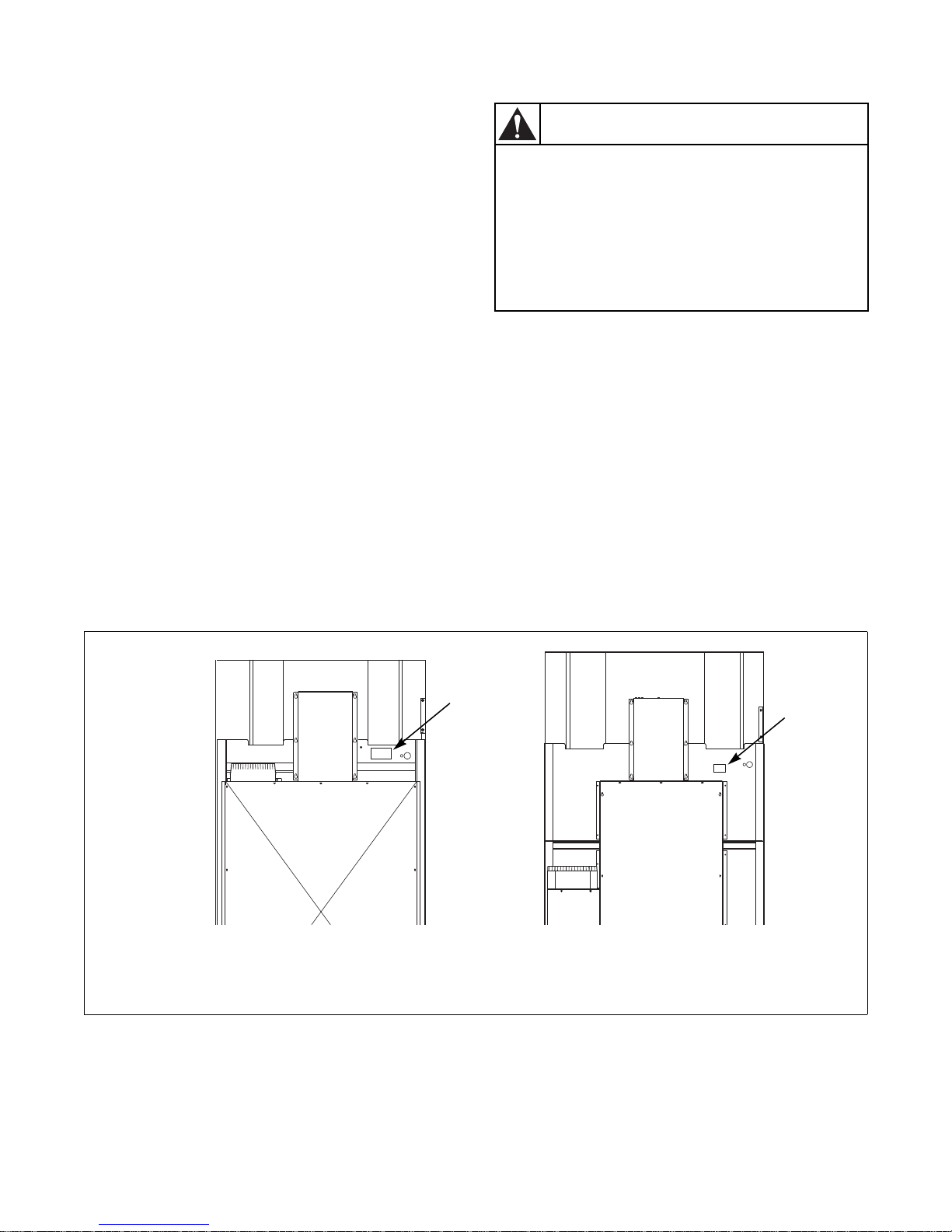
When calling or writing about your unit, PLEASE
GIVE THE MODEL AND SERIAL NUMBERS. The
model and serial numbers are located on the
nameplate. The nameplate will be in the location
shown in Figure 1.
Date Purchased ______________________________
Model Number ______________________________
Serial Number _______________________________
Introduction
If replacement parts are required, contact the source
from where you purchased your tumble dryer or call
+1 (920) 748-3950 or +32 56 41 20 54 for the name
and address of the nearest authorized parts distributor.
Please include a copy of your bill of sale and any
service receipts you have.
1 Serial Plate
TMB2288N
Figure 1
70458101 (EN)
© Copyright, Alliance Laundry Systems LLC – DO NOT COPY or TRANSMIT
7
Safety Information
Indicates an imminently hazardous
situation that, if not avoided, will cause
severe personal injury or death.
DANGER
Indicates a hazardous situation that, if not
avoided, could cause severe personal
injury or death.
WARNING
Indicates a hazardous situation that, if not
avoided, may cause minor or moderate
personal injury or property damage.
CAUTION
Failure to install, maintain, and/or operate
this machine according to manufacturer’s
instructions may result in conditions which
can produce serious injury, death and/or
property damage.
W051R1
WARNING
Precautionary statements (“DANGER,” “WARNING,”
and “CAUTION”), followed by specific instructions,
are found in this manual and on machine decals. These
precautions are intended for the personal safety of the
operator, user, servicer, and those maintaining the
machine.
NOTE: The word “NOTE” is used to communicate
installation, operation, maintenance or servicing
information that is important but not hazard
related.
NOTE: The WARNING and IMPORTANT
instructions appearing in this manual are not
meant to cover all possible conditions and
situations that may occur. It must be understood
that common sense, caution and carefulness are
factors which CANNOT be built into this tumble
dryer. These factors MUST BE supplied by the
person(s) installing, maintaining or operating the
tumble dryer.
Additional precautionary statements (“IMPORTANT”
and “NOTE”) are followed by specific instructions.
IMPORTANT: The word “IMPORTANT” is used
to inform the reader of specific procedures where
minor machine damage will occur if the procedure
is not followed.
Always contact your dealer, distributor, service agent
or the manufacturer on any problems or conditions you
do not understand.
8
© Copyright, Alliance Laundry Systems LLC – DO NOT COPY or TRANSMIT
70458101 (EN)

Save These Instructions
To reduce the risk of fire, electric shock,
serious injury or death to persons when
using your tumbler, follow these basic
precautions.
W776
WARNING
Safety Information
Important Safety Instructions
1. Read all instructions before using the tumble
dryer.
2. Install the tumble dryer according to the
INSTALLATION instructions. Refer to the
EARTHING (grounding) instructions for the
proper earthing (grounding) of the tumble dryer.
All connections for electrical power, earthing
(grounding) and gas supply must comply with
local codes and be made by licensed personnel
when required. It is recommended that the
machine be installed by qualified technicians.
3. Do not install or store the tumble dryer where it
will be exposed to water and/or weather. The
tumble dryer cannot be used in a closed room
where the air supply is insufficient. If necessary,
ventilation grids must be installed in the doors or
the windows.
4. This appliance must not be activated without lint/
foam filter.
5. When you perceive a gas odor, immediately
switch off the gas supply and ventilate the room.
Do not switch on electrical appliances and do not
pull electrical switches. Do not use matches or
lighters. Do not use a phone in the building. Warn
the fitter, and if so desired, the gas company, as
soon as possible.
6. To avoid fire and explosion, keep surrounding
areas free of flammable and combustible
products. Regularly clean the dryer drum and
exhaust tube should be cleaned periodically by
competent maintenance personnel. Daily remove
piled up dust from filter and inside of filter
compartment.
7. Do not use or store flammable materials near this
appliance.
8. Do not dry articles that have been previously
cleaned in, washed in, soaked in or spotted with
gasoline or machine oils, vegetable or cooking
oils, cleaning waxes or chemicals, dry-cleaning
solvents, thinner or other flammable or explosive
substances as they give off vapors that could
ignite, explode or cause fabric to catch on fire by
itself.
9. Do not spray aerosols in the vicinity of this
appliance while it is in operation.
10. Items such as foam rubber (latex foam), shower
caps, waterproof textiles, rubber backed articles
and clothes or pillows filled with foam rubber
pads should not be dried in the tumble dryer. Do
not use the appliance to dry materials with a low
melting temperature (PVC, rubber, etc.).
11. Do not tumble fiberglass curtains and draperies
unless the label says it can be done. If they are
dried, wipe out the cylinder with a damp cloth to
remove particles of fiberglass.
12. Do not allow children on or in the tumble dryer.
This appliance is not intended for use by young
children or infirm persons without supervision.
Young children should be supervised to ensure
that they do not play with the appliance.
13. Do not reach into the tumble dryer if the cylinder
is revolving.
14. Use tumble dryer only for its intended purpose,
drying fabrics. Always follow the fabric care
instructions supplied by the textile manufacturer
and only use the dryer drum to dry textiles that
have been washed in water. Only insert spindried linen in the dryer.
15. Always read and follow manufacturer’s
instructions on packages of laundry and cleaning
aids. Heed all warnings or precautions. To reduce
the risk of poisoning or chemical burns, keep
them out of the reach of children at all times
(preferably in a locked cabinet).
16. Do not use fabric softeners or products to
eliminate static unless recommended by the
manufacturer of the fabric softener or product.
17. Remove laundry immediately after tumble dryer
stops.
70458101 (EN)
© Copyright, Alliance Laundry Systems LLC – DO NOT COPY or TRANSMIT
9

Safety Information
18. DO NOT operate the tumble dryer if it is
smoking, grinding or has missing or broken parts
or removed guards or panels. DO NOT tamper
with the controls or bypass any safety devices.
19. Tumble dryer will not operate with the loading
door open. DO NOT bypass the door safety
switch to permit the tumble dryer to operate with
the door open. The tumble dryer will stop
tumbling when the door is opened. Do not use the
tumble dryer if it does not stop tumbling when
the door is opened or starts tumbling without
pressing or turning the START mechanism.
Remove the tumble dryer from use and call for
service.
20. Tumble dryer(s) will not operate with lint panel
open. DO NOT bypass lint panel safety switch to
permit the tumble dryer to operate with the lint
panel open.
21. Do not modify this appliance.
22. Always clean the lint filter daily. Keep area
around the exhaust opening and adjacent
surrounding area free from the accumulation of
lint, dust and dirt. The interior of the tumble
dryer and the exhaust duct should be cleaned
periodically by qualified service personnel.
23. Solvent vapors from dry-cleaning machines
create acids when drawn through the heater of the
drying unit. These acids are corrosive to the
tumble dryer as well as the laundry load being
dried. Be sure make-up air is free of solvent
vapors.
24. At the end of each working day, close off all main
supplies of gas, steam and current.
25. Do not repair or replace any part of the tumble
dryer, or attempt any servicing unless specifically
recommended in the user-maintenance
instructions or in published user-repair
instructions that the user understands and has the
skills to carry out. ALWAYS disconnect and
lockout the electrical power to the tumble dryer
before servicing. Disconnect power by shutting
off appropriate breaker or fuse.
26. Before the tumble dryer is removed from service
or discarded, remove the door to the drying
compartment and the door to the lint
compartment.
27. Failure to install, maintain, and/or operate this
tumble dryer according to the manufacturer’s
instructions may result in conditions which can
produce bodily injury and/or property damage.
NOTE: The WARNINGS and IMPORTANT
SAFETY INSTRUCTIONS appearing in this
manual are not meant to cover all possible
conditions and situations that may occur. Common
sense, caution and care must be exercised when
installing, maintaining, or operating the tumble
dryer.
Always contact your dealer, distributor, service agent
or the manufacturer on any problems or conditions you
do not understand.
10
© Copyright, Alliance Laundry Systems LLC – DO NOT COPY or TRANSMIT
70458101 (EN)

Specifications and Dimensions
Specifications 120 Series 170 Series 200 Series
Noise level measured during
operation at operator position of
1 meter (3.3 feet) in front of
machine and 1.6 meters (5.2 feet)
from floor.
Cylinder Size:
mm (Inches)
Cylinder Capacity dry weight:
kg (Pounds)
Gas and
Standard Packaging
Weight: kg (Pounds)
Standard Packaging Shipping
Dimensions: mm (Inch)
Slat Crate Packaging
Weight: kg (Pounds)
Slat Crate Shipping Dimensions:
mm (Inch)
Cylinder Motor: kW (HP) 0.560 (0.75) 0.560 (0.75) 0.560 (0.75)
Fan Motor: kW (HP) 0.746 (1) 2.238 (3) 2.238 (3)
Air Outlet Diameter:
mm (Inches)
Maximum Static Back Pressure:
mbar (W.C.I.)
Maximum Airflow:
L/sec. (C.F.M)
Net Weight (approximate):
kg (Pounds)
Gas Connection 3/4 in. NPT 1 in. NPT 1 in. NPT
Gas Burner Rating:
kW (Btu/hr.)
Net Weight (approximate):
kg (Pounds)
Steam Connection
Steam Coil Rating at 100 psig:
kg/hr. (Btu/hr.) (recommended
operating pressure 80-100 psig)
Heating Element Rating:
Kilowatts (kW)
Electric
Steam
Gas and
Electric
Steam
66 dBA 66 dBA 66 dBA
1118 x 1041
(44 x 41)
54.4
(120)
607
(1338)
656
(1446)
1232 x 1829 x 2286
(48.5 x 72 x 90)
656
(1447)
702
(1547)
1308 x 1880 x 2305
(51.5 x 74 x 90.75)
254
(10)
0.8
(0.3)
755
(1600)
Gas Models
578
(1275)
79.13
(270,000)
Steam Models
624
(1375)
3/4 in. NPT inlet
3/4 in. NPT outlet
183.1
(405,000)
Electric Models
60 kW Not Applicable Not Applicable
1289 x 1080
(50.75 x 42.5)
77.1
(170)
756
(1667)
806
(1776)
1473 x 1892 x 2515
(58 x 74.5 x 99)
812
(1791)
858
(1891)
1549 x 1943 x 2534
(1 x 76.5 x 99.75)
300
(12)
0.8
(0.3)
1156
(2450)
716
(1575)
115.77
(395,000)
761
(1675)
3/4 in. NPT inlet
1 in. NPT outlet
294.2
(648,000)
1422 x 2032 x 2515
1549 x 2108 x 2565
(61 x 83 x 101)
3/4 in. NPT inlet
1 in. NPT outlet
1289 x 1270
(50.75 x 50)
90.7
(200)
779
(1718)
825
(1818)
(56 x 80 x 99)
848
(1868)
893
(1968)
300
(12)
0.8
(0.3)
1156
(2450)
774
(1707)
124.56
(425,000)
820
(1807)
294.2
(648,000)
NOTE: All machines are shipped with extra nipple
to convert to metric thread (from Standard).
70458101 (EN)
© Copyright, Alliance Laundry Systems LLC – DO NOT COPY or TRANSMIT
11
Specifications and Dimensions
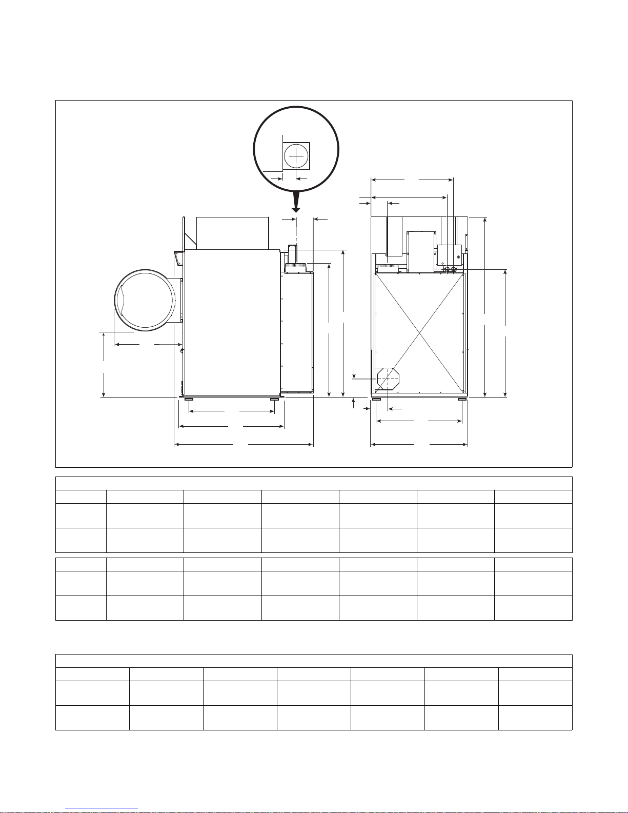
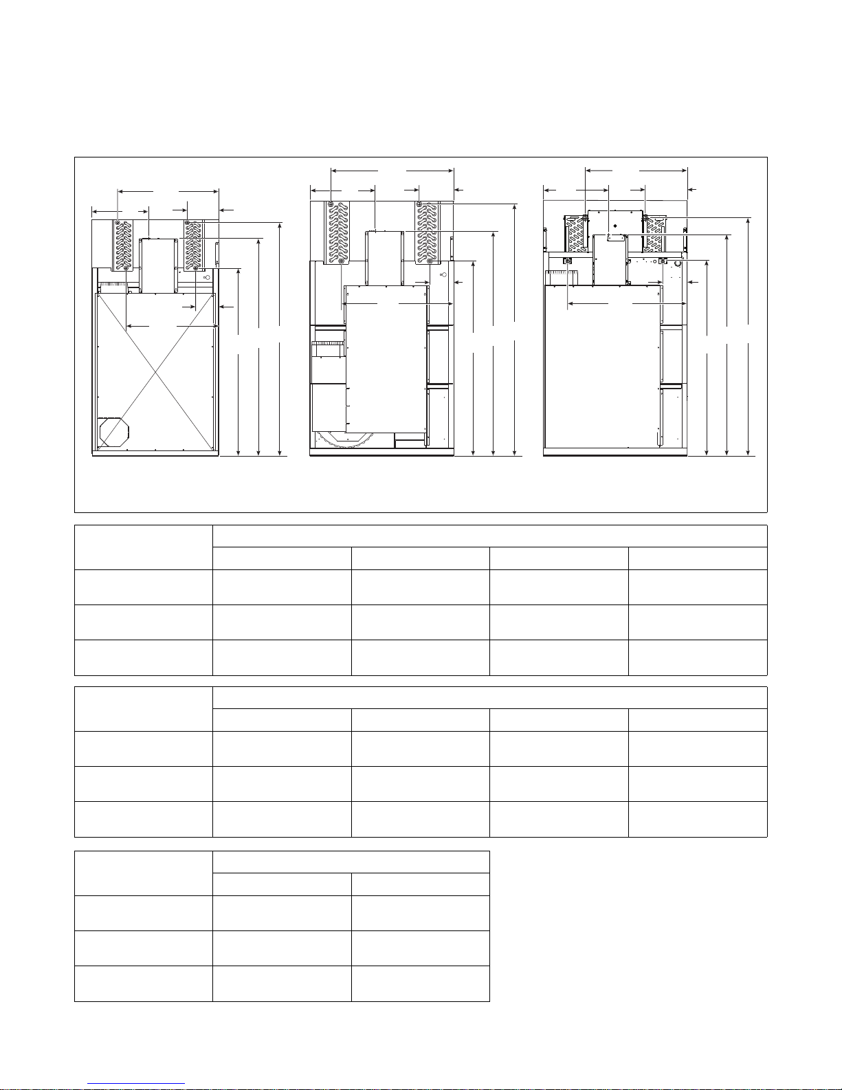
A
B
C
D
U
V
X
H
F
Z
Y
W
TOP VIEW
OF EXHAUST
DUCT
E
G
I
L
J
K
120 Series Tumble Dryer Dimensions
and Exhaust Outlet Locations
TMB2396N
ModelsABCDEF
120L/N/E
120S
797 mm
(31.38 in.)
797 mm
(31.38 in.)
826 mm
(32.5 in.)
826 mm
(32.5 in.)
Models G H I J* K* L*
120L/N/E
120S
1178 mm
(46.38 in.)
1178 mm
(46.38 in.)
2177 mm.
(85.7 in.)
2121 mm
(83.5 in.)
Cabinet Dimensions
1242 mm
(48.91 in.)
1242 mm
(48.91 in.)
1778 mm.
(70 in.)
1778 mm
(70 in.)
1268 mm
(49.91 in.)
1268 mm
(49.91 in.)
1057 mm
(41.6 in.)
1057 mm
(41.6 in.)
1725 mm
(67.92 in.)
1725 mm
(67.92 in.)
1097 mm
(43.2 in.)
1097 mm
(43.2 in.)
1153 mm
(45.38 in.)
1153 mm
(45.38 in.)
1562 mm
(61.5 in.)
1562 mm
(61.5 in.)
* Fire suppression system optional - may not be on machine.
Refer to Position and Level the Tumble Dryer to temporarily reduce the heights of these models.
Exhaust Outlet Dimensions and Locations
Models U V W X Y Z
120L/N/E
120S
1612 mm
(63.45 in.)
1542 mm
(60.7 in.)
214 mm
(8.44 in.)
214 mm
(8.44 in.)
127 mm
(5 in.)
127 mm
(5 in.)
208 mm
(8.18 in.)
208 mm
(8.18 in.)
173 mm
(6.82 in.)
173 mm
(6.82 in.)
208 mm
(8.18 in.)
208 mm
(8.18 in.)
12
© Copyright, Alliance Laundry Systems LLC – DO NOT COPY or TRANSMIT
70458101 (EN)
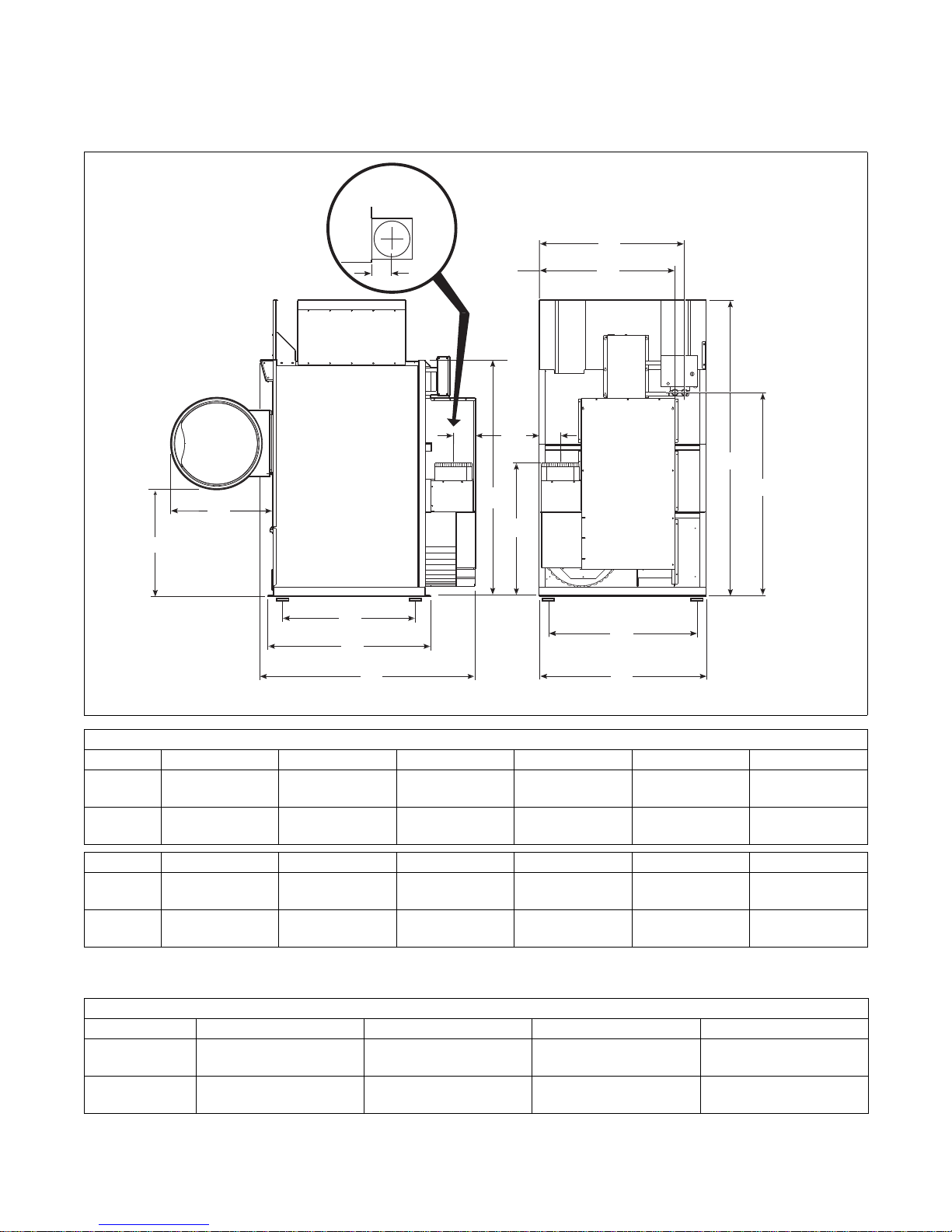
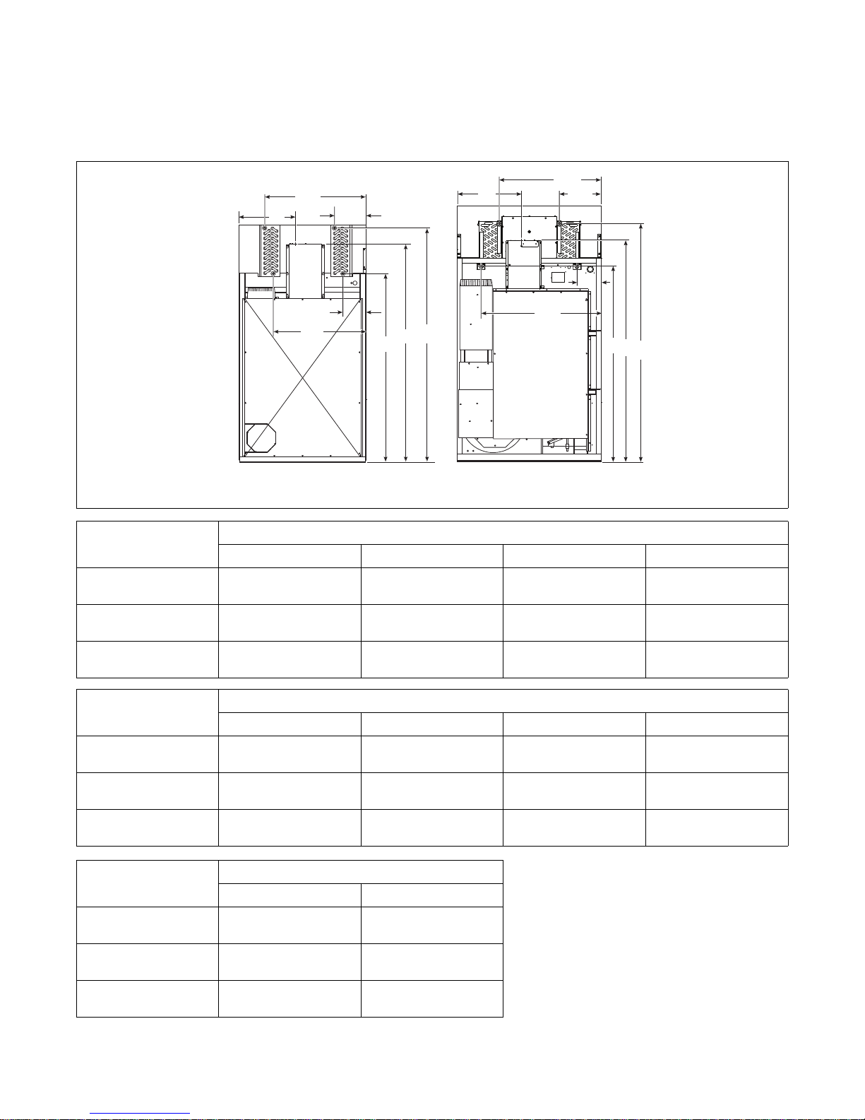
170 and 200 Series Tumble Dryer
A
B
C
D
W
H
F
Y
X
V
TOP VIEW
OF EXHAUST
DUCT
E
G
I
L
K
J
Dimensions and Exhaust Outlet Locations
Specifications and Dimensions
TMB2397N
ModelsABCDEF
170L/N/S
200L/N/S
860 mm
(33.86 in.)
815 mm
(32.1 in.)
826 mm
(32.5 in.)
904 mm
(35.6 in.)
Cabinet Dimensions
1289 mm
(50.75 in.)
1473 mm
(58 in.)
1314 mm
(51.75 in.)
1505 mm
(59.25 in.)
1749 mm
(68.85 in.)
1939 mm
(76.35 in.)
1324 mm
(52.12 in.)
1324 mm
(52.12 in.)
Models G H I J* K* L*
170L/N/S
200L/N/S
1349 mm
(53.12 in.)
1349 mm
(53.12 in.)
2388 mm
(94 in.)
2388 mm
(94 in.)
1908 mm
(75.12 in.)
1908 mm
(75.12 in.)
1241 mm
(48.86 in.)
1241 mm
(48.86 in.)
1281 mm
(50.45 in.)
1281 mm
(50.45 in.)
1588 mm
(62.5 in.)
1588 mm
(62.5 in.)
* Fire suppression system optional - may not be on machine.
Refer to Position and Level the Tumble Dryer to temporarily reduce the heights of these models.
Exhaust Outlet Dimensions and Locations
Models U V W X
170L/N/S
200L/N/S
1076 mm
(42.38 in.)
1076 mm
(42.38 in.)
171 mm
(6.75 in.)
171 mm
(6.75 in.)
152 mm
(6 in.)
152 mm
(6 in.)
178 mm
(7 in.)
178 mm
(7 in.)
70458101 (EN)
© Copyright, Alliance Laundry Systems LLC – DO NOT COPY or TRANSMIT
13
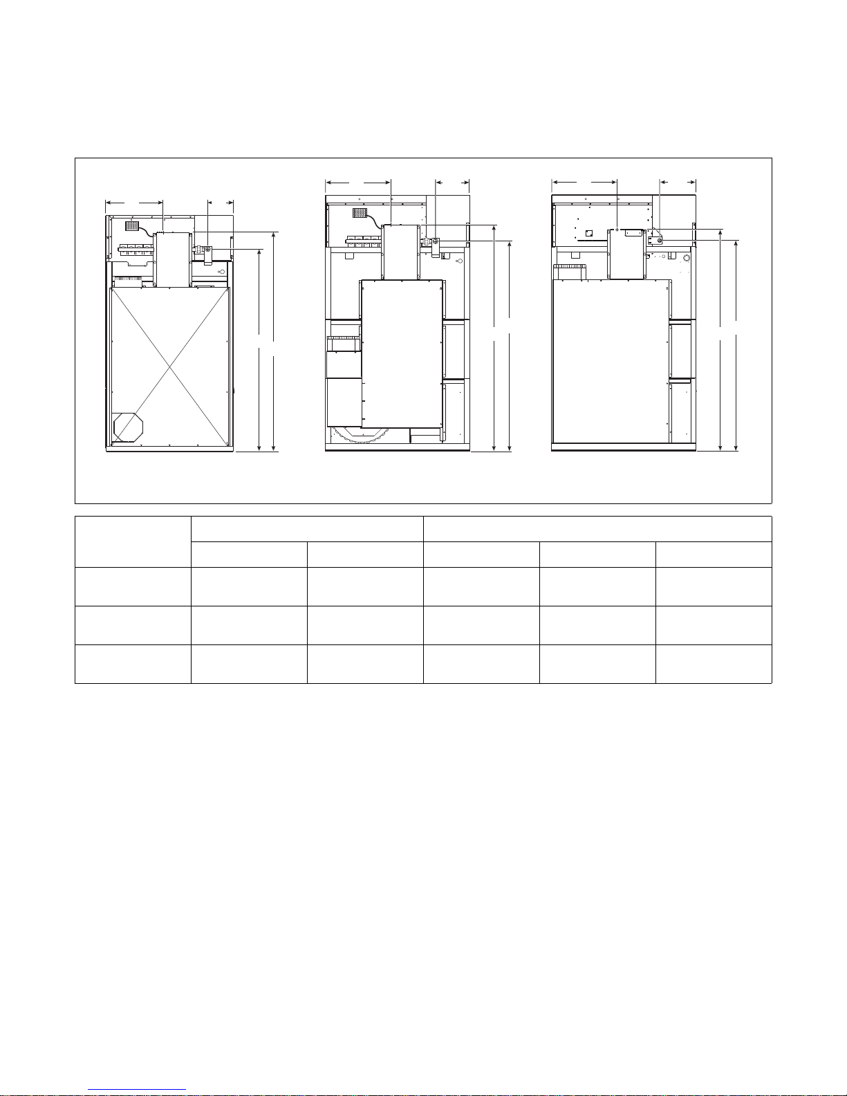
Specifications and Dimensions
A
C
C
A
B
B
D
120L/N 170L/N
D
C
A
B
D
200L/N
Electric and Gas Connection
Locations for Gas Models Through
3/10/13
TMB2255N TMB2382N
Electrical Connection Gas Connection
Models
ABCDDiameter
120L/N
170L/N
200L/N
466 mm
(18.34 in.)
533 mm
(21 in.)
533 mm
(21 in.)
1977 mm
(77.84 in.)
2057 mm
(81 in.)
2057 mm
(81 in.)
318 mm
(12.5 in.)
377 mm
(14.85 in.)
348 mm
(13.7 in.)
1791 mm
(70.5 in.)
1966 mm
(77.4 in.)
1966 mm
(77.4 in.)
3/4 in. NPT
1 in. NPT
1 in. NPT
14
© Copyright, Alliance Laundry Systems LLC – DO NOT COPY or TRANSMIT
70458101 (EN)
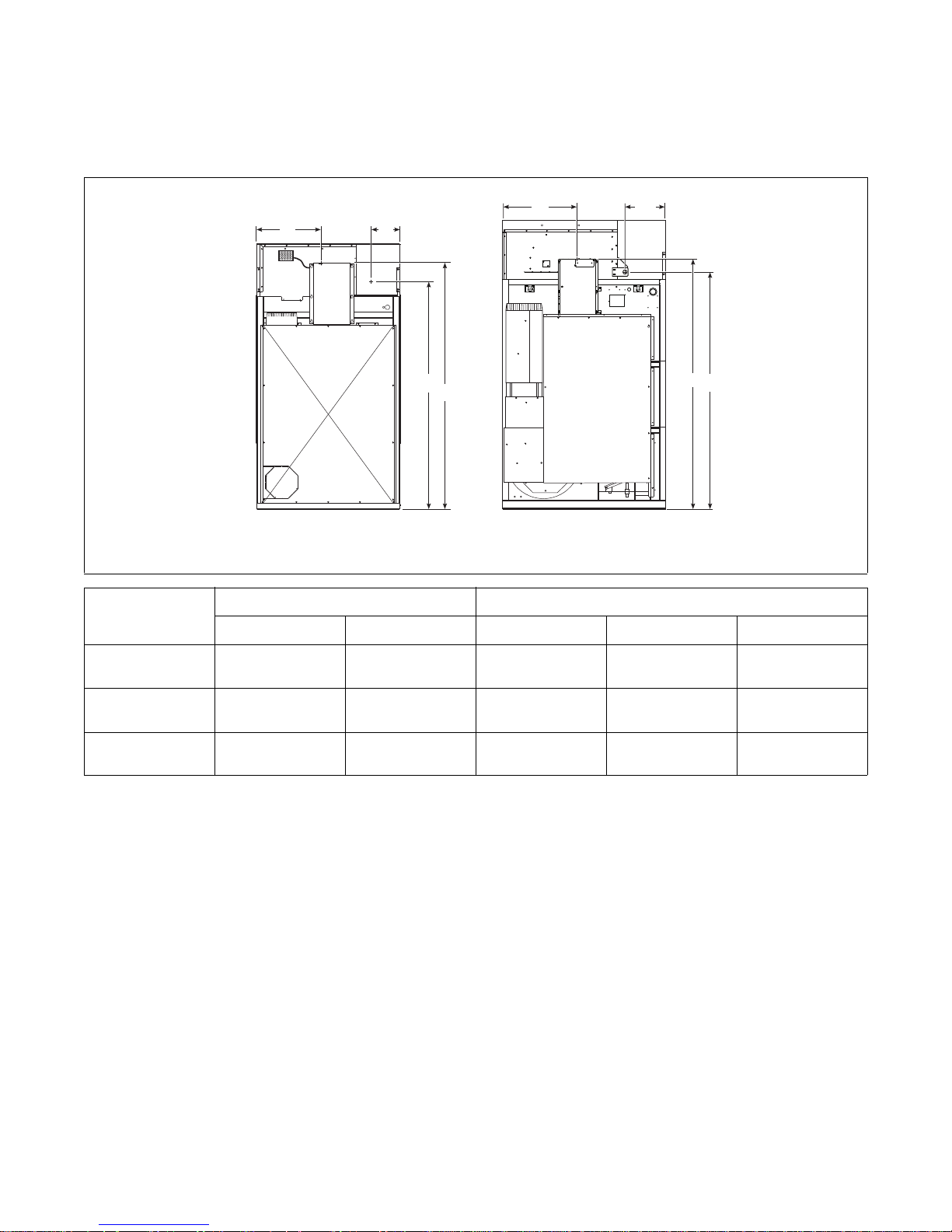
Electric and Gas Connection
A
C
D
170L/N AND 200L/N
B
C
A
B
D
120L/N
Locations for Gas Models Starting
3/11/13
Specifications and Dimensions
Models
120L/N
170L/N
200L/N
TMB2400N
Electrical Connection Gas Connection
ABCDDiameter
466 mm
(18.34 in.)
533 mm
(21 in.)
533 mm
(21 in.)
1977 mm
(77.84 in.)
2057 mm
(81 in.)
2057 mm
(81 in.)
318 mm
(12.5 in.)
377 mm
(14.85 in.)
377 mm
(14.85 in.)
1791 mm
(70.5 in.)
1966 mm
(77.4 in.)
1966 mm
(77.4 in.)
3/4 in. NPT
1 in. NPT
1 in. NPT
70458101 (EN)
© Copyright, Alliance Laundry Systems LLC – DO NOT COPY or TRANSMIT
15
Specifications and Dimensions
A1
B1
120S 170S
A2
B2
D
E
F
A1
B1
B2
A2
D
E
F
C
C
A1
B1
B2
A2
D
E
F
C
200S
Electric and Steam Connection
Locations for Steam Models
Through 3/10/13
TMB2256 TMB2383N
Steam Inlet
Models
Diameter A1 A2 F
120S
170S
200S
3/4 in. NPT
3/4 in. NPT
3/4 in. NPT
911 mm
(35.875 in.)
956 mm
(37.625 in.)
956 mm
(37.625 in.)
340 mm
(13.375 in.)
387 mm
(15.25 in.)
387 mm
(15.25 in.)
2102 mm
(82.75 in.)
2235 mm
(88 in.)
2235 mm
(88 in.)
Steam Outlet
Models
Diameter B1 B2 D
120S
170S
200S
3/4 in. NPT
1 in. NPT
1 in. NPT
879 mm
(34.625 in.)
1133 mm
(44.625 in.)
1133 mm
(44.625 in.)
333 mm
(13.125 in.)
222 mm
(8.75 in.)
222 mm
(8.75 in.)
1740 mm
(68.5 in.)
1822 mm
(71.75 in.)
1822 mm
(71.75 in.)
Electrical Connection
Models
120S
170S
200S
CE
466 mm
(18.34 in.)
533 mm
(21 in.)
533 mm
(21 in.)
1977 mm
(77.84 in.)
2057 mm
(81 in.)
2057 mm
(81 in.)
16
© Copyright, Alliance Laundry Systems LLC – DO NOT COPY or TRANSMIT
70458101 (EN)
Electric and Steam Connection
A1
B1
120S
170S AND 200S
A2
B2
A1
B1
B2
A2
D
E
F
C
D
E
F
C
Locations for Steam Models
Through 3/11/13
Specifications and Dimensions
Models
120S
170S
200S
Models
120S
170S
200S
Models
120S
170S
200S
TMB2401N
Steam Inlet
Diameter A1 A2 F
3/4 in. NPT
3/4 in. NPT
3/4 in. NPT
911 mm
(35.875 in.)
956 mm
(37.625 in.)
956 mm
(37.625 in.)
340 mm
(13.375 in.)
394 mm
(15.5 in.)
394 mm
(15.5 in.)
2102 mm
(82.75 in.)
2226 mm
(87.625 in.)
2226 mm
(87.625 in.)
Steam Outlet
Diameter B1 B2 D
3/4 in. NPT
1 in. NPT
1 in. NPT
879 mm
(34.625 in.)
1133 mm
(44.125 in.)
1133 mm
(44.125 in.)
333 mm
(13.125 in.)
229 mm
(9 in.)
229 mm
(9 in.)
1740 mm
(68.5 in.)
1832 mm
(72.125 in.)
1832 mm
(72.125 in.)
Electrical Connection
CE
466 mm
(18.34 in.)
533 mm
(21 in.)
533 mm
(21 in.)
1977 mm
(77.84 in.)
2057 mm
(81 in.)
2057 mm
(81 in.)
70458101 (EN)
© Copyright, Alliance Laundry Systems LLC – DO NOT COPY or TRANSMIT
17
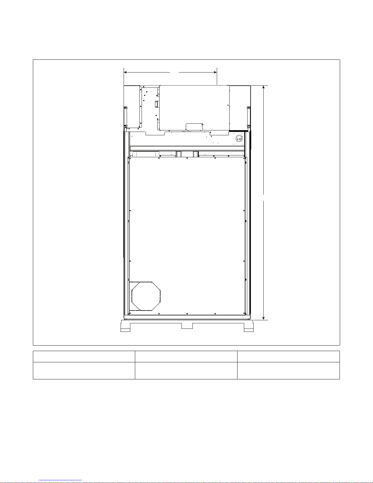
Specifications and Dimensions
A
B
Electric Connection Location for
Electric Models
Models A B
120E
910 mm
(35.81 in.)
2175 mm
(85.64 in.)
TMB2336N
18
© Copyright, Alliance Laundry Systems LLC – DO NOT COPY or TRANSMIT
70458101 (EN)

Installation
Pre-Installation Inspection
Upon delivery, visually inspect the crate, carton and
parts for any visible shipping damage. If the crate,
carton, or cover is damaged or signs of possible
damage are evident, have the carrier note the condition
on the shipping papers before the shipping receipt is
signed, or advise the carrier of the condition as soon as
it is discovered.
Remove the crate and protective cover as soon as
possible and check the items listed on the packing list.
Advise the carrier of any damaged or missing articles
as soon as possible. A written claim should be filed
with the carrier immediately if articles are damaged or
missing.
IMPORTANT: Remove the shipping tape from the
two back draft dampers located in the exhaust
outlet.
IMPORTANT: Warranty is void unless tumble
dryer is installed according to instructions in this
manual. Installation should comply with minimum
specifications and requirements detailed in this
manual and applicable local gas fitting regulations,
municipal building codes, water supply regulations,
electrical wiring regulations, and any other
relevant statutory regulations. Due to varied
requirements, applicable local codes should be
thoroughly understood and all pre-installation
work arranged for accordingly.
Materials Required (Obtain Locally)
One Single Pole fused disconnect
All Models
Gas Models
Steam Models
switch or circuit breaker on 1 Phase
models.
Circuit breaker on 3 Phase models.
One gas shut-off valve for gas service
line to each tumble dryer.
One steam shut-off valve for steam
service line to be connected upstream of
solenoid steam valve.
Two steam shut-off valves for each
condensate return line.
Flexible steam hoses with a
8.79 kg/sq. cm (125 psig [pounds per
square inch gauge]) working pressure
for connecting steam coils. Refer to
Figure 19 and Figure 20 for sizing and
connection configurations.
Two steam traps for steam coil outlets
to condensate return line.
Optional – Two vacuum breakers for
condensate return lines.
IMPORTANT: 3 Phase Only – Each tumble dryer
must be connected to its own individual branch
circuit breaker, not fuses, to avoid the possibility of
“single phasing” and causing premature failure of
the motor(s).
Location Requirements
70458101 (EN)
The tumble dryer must be installed on a level floor.
Floor covering materials such as carpeting or tile
should be removed.
To assure compliance, consult local building code
requirements. The tumble dryer must not be installed
or stored in area where it will be exposed to water and/
or weather.
IMPORTANT: DO NOT block the airflow at the
rear of the tumble dryer with laundry or other
articles. Doing so would prevent adequate air
supply to the combustion chamber of the tumble
dryer.
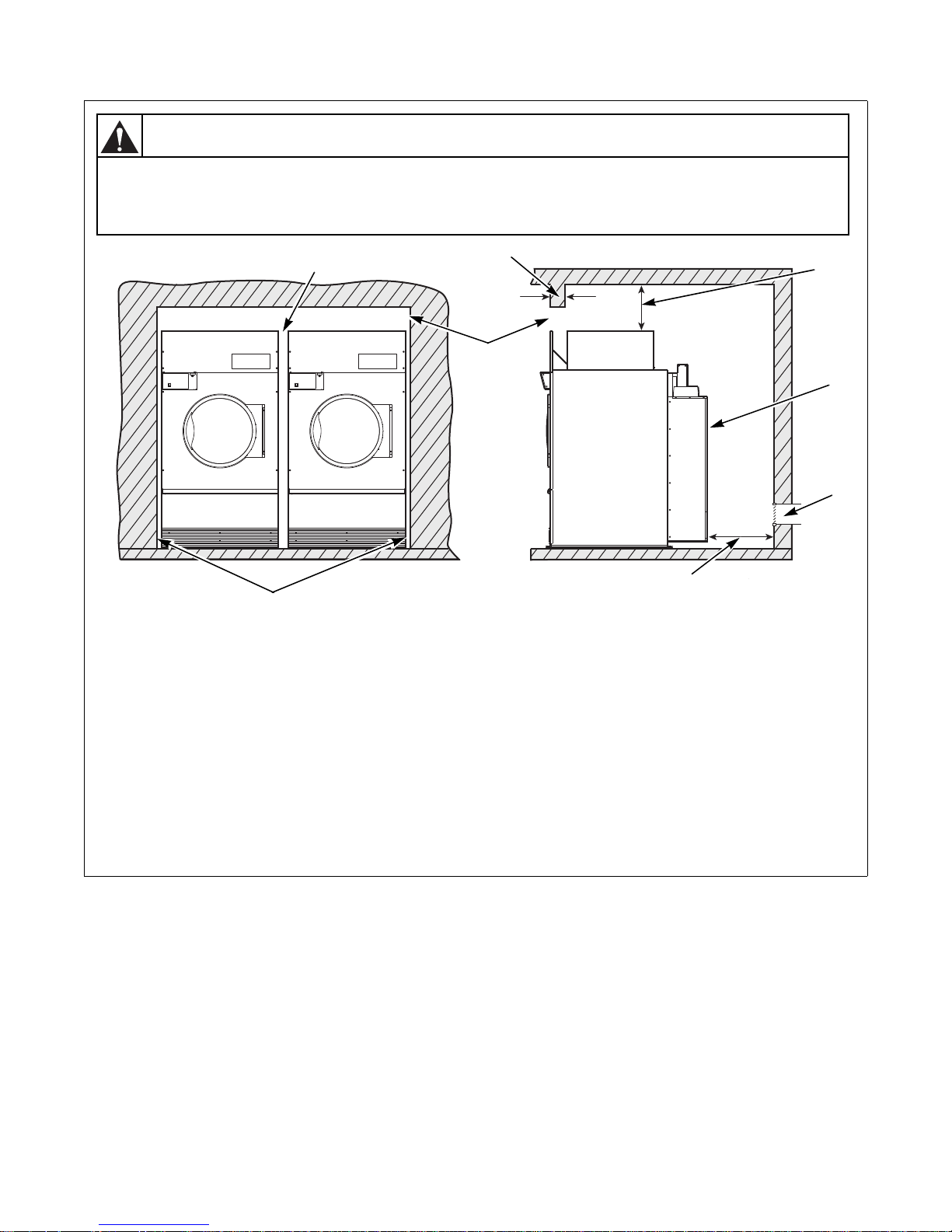
A typical tumble dryer enclosure is shown in Figure 2.
IMPORTANT: Install tumble dryers with sufficient
clearance for servicing and operation, refer to
Figure 2.
© Copyright, Alliance Laundry Systems LLC – DO NOT COPY or TRANSMIT
19
Installation
TMB2020N
3
1
4
5
6
7
2
WARNING
To reduce the risk of severe injury, clearance of tumbler cabinet from combustible
construction must conform to the minimum clearances, and/or local codes and
ordinances.
W770
8
NOTE: Shaded areas indicate adjacent structure.
1 13 mm (0.5 in.) recommended between machines for removal or installation
2 Allow 51-102 mm (2-4 in.) opening at top of machine to aid in removal or installation. A removable trim piece
may be used to conceal the opening; zero clearance allowed for trim
3 102 mm (4 in.) maximum header thickness
4 Minimum clearance permitted for remainder: Gas and Electric 102 mm (4 in.), Steam 305 mm (12 in.)
5 Guard
6 Provision for make-up air
7 610 mm (24 in.) minimum, 914 mm (36 in.) recommended for maintenance purposes
8 6 mm (0.25 in.) recommended for removal or installation purposes, zero clearance allowed
Figure 2
TMB2020N
20
© Copyright, Alliance Laundry Systems LLC – DO NOT COPY or TRANSMIT
70458101 (EN)

Installation
Position and Level the Tumble Dryer
The tumble dryer may be moved with or without the
skid. To remove the skid, unscrew the four shipping
bolts, and discard them.
To fit a 170 and 200 series tumble dryer (with shipping
skid) through a 2.43 meters (8 foot) high door, you
must remove the front access panel. The upper 76 mm
(3 inches) of the stove must also be removed on
170 series gas tumble dryers. Removing the entire gas
or steam heater assembly and the shipping skid, will
reduce the height of the 120 series tumble dryer to
1778 mm (70 inches), and the 170 and 200 series
tumble dryer to 1905 mm (75 inches).
Level the tumble dryer to within 3 mm (0.125 inch)
from front-to-rear (level on cylinder rib), and side-toside (level on top panel). Shim under corners to level
and stabilize unit. Tumble dryer must not rock.
Fire Suppression System
Check Local Codes and Permits
Call your local water company or the proper municipal
authority for information regarding local codes.
IMPORTANT: It is your responsibility to have
ALL plumbing connections made by a qualified
professional to assure that the plumbing is
adequate and conforms to local, state, and federal
regulations or codes.
IMPORTANT: It is the installation or owner’s
responsibility to see that the necessary or required
water, water pressure, pipe size, or connections are
provided. Manufacturer assumes no responsibility
if the fire suppression system is not connected,
installed, or maintained properly.
Water Requirements
IMPORTANT: Water must be supplied to the fire
suppression system, or the fire suppression system
will not operate as intended.
Connection point to the electric water solenoid valve is
a 19 mm (3/4 inch) hose. The fire suppression system
equipped tumble dryer must be supplied with a
minimum water pipe size of 12.7 mm (1/2 inch) and be
provided with a
maximum of 827 kPa (120 psi) of pressure at all times.
Flow rate must be no less than, but approximately
57 liters (15 gallons) per minute.
minimum of 138 kPa (20 psi) and a
NOTE: Water pressure under 138 kPa (20 psi) will
cause low flow and water leakage at water solenoid
valve.
If the rear of the tumble dryer or the water supply is
located in an area where it will be exposed to cold/
freezing temperatures, provisions must be made to
protect these water lines from freezing.
IMPORTANT: Temperature of the water supply
must be kept between 4.4°C and 48.9°C (40°F and
120°F). If water in the supply line or water solenoid
valve freezes, the fire suppression system will not
operate.
70458101 (EN)
© Copyright, Alliance Laundry Systems LLC – DO NOT COPY or TRANSMIT
21
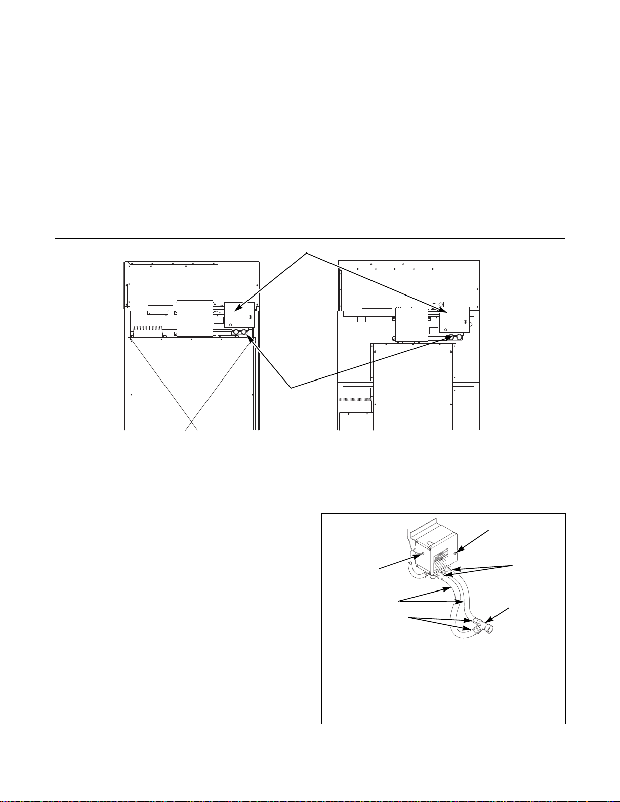
Installation
1
2
120 SERIES
170 AND 200 SERIES
1
2
3
2
4
5
IMPORTANT: If temperature sensors inside the
tumble dryer register a temperature below 4.4°C
(40°F), the fire suppression system control will lock
out. This feature protects against operation of the
tumble dryer with a possible frozen water supply.
Only when the temperature sensors register a
temperature above 4.4°C (40°F) will the machine
reset for operation.
IMPORTANT: Flexible supply line/coupling must
be used. Solenoid valve failure due to hard
plumbing connections will void the warranty. It is
recommended that a filter or strainer be installed
in the water supply line.
Water Connections
Two hoses and a Y-valve are provided with the tumble
dryer to allow for connection of water supply to
tumble dryer. The water connections are made to the
bushings of the water solenoid valve, located on the
rear of the tumble dryer. The Y-valve provides a single
female hose connection (Standard US 3/4-11 1/2 NH
thread). Refer to Figure 3 and Figure 4.
1 Fire Suppression System Control Box 2 Water Solenoid Valve
To connect the two hoses (supplied with tumble
dryer), insert rubber washers (from literature pack) in
water inlet hose couplings. Refer to Figure 4.
TMB2012N
Figure 3
TMB2008N
1 Lock
2 Hose Couplings
3 Y Valve
4 Inlet Hoses
5 Opening for Auxiliary Alarm Cable
Figure 4
22
© Copyright, Alliance Laundry Systems LLC – DO NOT COPY or TRANSMIT
70458101 (EN)
 Loading...