

ALLIANCE GU050N, HA050L, HA050N, HT050L, HT050N Service Manual
...
Drying Tumblers
50 Pound Capacity
Refer to Page 5 for Model Numbers
Service
www.comlaundry.com
TMB795C
Part No. 70269301
January 2003

Table of Contents
Section 1 –Safety Information
Locating An Authorized Service Person..................4
Section 2 –Introduction
Model Identification.................................................5
Customer Service.....................................................6
Serial Plate Location................................................6
Wiring Diagram .......................................................6
Safety Warnings and Decals ....................................7
Safety Precautions for Servicing Tumblers .............7
How A Tumbler Works ...........................................8
Section 3 –Troubleshooting
1. Motor Does Not Start.........................................9
2. Motor Overload Protector Cycles Repeatedly.10
3. Motor Runs But Cylinder Does Not Turn. ......10
4. Motor Does Not Stop.......................................10
5. Heating Element Does Not Heat or Burner
Does Not Ignite................................................11
6. Igniter Does Not Shut Off After Gas Ignition —
Gas Burner .......................................................13
7. Heating Element or Burner Shuts off
Prematurely......................................................13
8. Heating Element or Burner Repeatedly Cycles
Off On High Limit Thermostat........................14
9. Heating Element or Burner Does Not
Shut-off 14
10. Clothes Do Not Dry.........................................14
11. Tumbler Overheating.......................................15
12. Burners Not Burning Properly
— Gas Models .................................................15
13. Loading Door Opens During Operation ..........15
14. Tumbler Runs But No Steam To Coils
— Steam Models..............................................16
15. Water In Steam Line — Steam Models...........16
16. Troubleshooting Electronic Control Models ...17
17. Tumbler Will Not Start, Time on
Drying Timer, Door Closed .............................18
18. Motor Runs, Time on Drying Timer
But No Heat .....................................................19
19. No Main Burner Flame, Igniter Does
Not Spark .........................................................20
20. Steam OM Models: No Heat with cycle selected,
unit running and calling for heat......................21
21. OM and RM Models: No Start with cycle
selected, start button pressed and door closed .22
22. OM Models: No Display after selecting one of
the ON/SELECT keys......................................23
23. Electric OM Models: No Heat with cycle
selected, unit running and calling for heat.......24
24. Gas OM Models: No Heat with cycle selected,
unit running and calling for heat......................25
25. OM Models: No fan motor rotation with cycle
selected and start pressed.................................26
26. OM Reversing Models: No cylinder rotation or
reversing capabilities .......................................27
27. CD Models: No start with vend satisfied and start
button pressed in ..............................................28
28. CD Models: No Heat with vend satisfied and unit
running.............................................................29
29. CD Models: No start with vend satisfied and start
button pushed...................................................30
Section 4 –Grounding
Grounding Instructions ..........................................31
Section 5 –Service Procedures
30. Controls ...........................................................33
31. Push-to-Start Switch........................................33
32. Cooling, Drying, or Run Light ........................33
33. Coin Meter.......................................................34
34. Coin Meter Timer Motor .................................34
35. Coin Meter Run or Heat Switch ......................34
36. Igniter...............................................................36
37. Ignition Control ...............................................36
38. Gas Valve.........................................................36
39. Burner Tube.....................................................36
40. Contactors and Terminal Block.......................38
41. Heater Element ................................................38
42. Stove High Limit Thermostat..........................40
43. Cabinet High Limit Thermostat.......................41
44. High Limit Thermostat ....................................42
45. Thermistor .......................................................42
46. Steam Coils......................................................42
47. Loading Door Assembly..................................43
48. Door Hinge ......................................................43
49. Loading Door Handle ......................................43
50. Front Panel.......................................................44
51. Airflow Switch ................................................45
52. Drive Guard .....................................................45
53. Drive Belt ........................................................45
(continued)
© Copyright 2003, Alliance Laundry Systems LLC
All rights reserved. No part of the contents of this book may be reproduced or transmitted in any form or by any means without
the expressed written consent of the publisher.
70269301 1
© Copyright, Alliance Laundry Systems LLC – DO NOT COPY or TRANSMIT

54. Drive Belt.........................................................46
55. Idler Shaft ........................................................47
56. Trunnion Housing Assembly...........................48
57. Trunnion Shaft Assembly................................49
58. Motor and Fan Assembly.................................50
59. Fan And Motor Assembly ...............................52
60. Cylinder Drive Motor ......................................53
Section 6 –Adjustments
61. Leveling Legs ..................................................55
62. Main Gas Burner Air Inlet Shutters.................56
63. Airflow Switch.................................................57
64. Loading Door Strike ........................................59
65. Drive Belt Tension...........................................59
66. Cylinder Clearance ..........................................62
2 70269301
© Copyright, Alliance Laundry Systems LLC – DO NOT COPY or TRANSMIT
Section 1
Safety Information
Throughout this manual and on machine decals, you
will find precautionary statements (“CAUTION”,
“WARNING”, and “DANGER”) followed by specific
instructions. These precautions are intended for the
personal safety of the operator, user, servicer, and those
maintaining the machine.
DANGER
DANGER indicates the presence of a
hazard that will cause severe personal
injury, death, or substantial property
damage if the danger is ignored.
WARNING
WARNING indicates the presence of a
hazard that can cause severe personal
injury, death, or substantial property
damage if the warning is ignored.
In the interest of safety, some general precautions
relating to the operation of this machine follow.
WARNING
• Failure to install, maintain and/or operate
this product according to the
manufacturer’s instructions may result in
conditions which can produce serious
injury, death and/or property damage.
• Do not repair or replace any part of the
product or attempt any servicing unless
specifically recommended or published in
this Service Manual and unless you
understand and have the skills to carry
out the servicing.
• Whenever ground wires are removed
during servicing, these ground wires
must be reconnected to ensure that the
product is properly grounded and to
reduce the risk of fire, electric shock,
serious injury or death.
W006R2
CAUTION
CAUTION indicates the presence of a
hazard that will or can cause minor
personal injury or property damage if the
caution is ignored.
Additional precautionary statements (“IMPORTANT”
and “NOTE”) are followed by specific instructions.
IMPORTANT: The word “IMPORTANT” is used
to inform the reader of specific procedures where
minor machine damage will occur if the procedure
is not followed.
NOTE: The word “NOTE” is used to communicate
installation, operation, maintenance or servicing
information that is important but not hazard
related.
70269301 3
© Copyright, Alliance Laundry Systems LLC – DO NOT COPY or TRANSMIT
Section 1 Safety Information
IMPORTANT INFORMATION: During the
lifetime of a tumbler, it may require service. The
information contained in this manual was written
and is intended for use by qualified service
technicians who are familiar with the safety
procedures required in the repair of a tumbler, and
who are equipped with the proper tools and testing
equipment.
WARNING
To reduce the risk of electric shock, fire,
explosion, serious injury or death:
• Disconnect electric power to the tumbler
before servicing.
• Never start the tumbler with any guards/
panels removed.
• Whenever ground wires are removed
during servicing, these ground wires
must be reconnected to ensure that the
tumbler is properly grounded.
W240
WARNING
NOTE: The WARNING and IMPORTANT
instructions appearing in this manual are not meant
to cover all possible conditions and situations that
may occur. It must be understood that common
sense, caution and carefulness are factors which
CANNOT be built into this tumbler. These factors
MUST BE supplied by the person(s) installing,
maintaining or operating the tumbler.
Always contact your dealer, distributor, service agent
or the manufacturer on any problems or conditions you
do not understand.
Locating An Authorized Service
Person
Alliance Laundry Systems is not responsible for
personal injury or property damage resulting from
improper service. Review all service information
before beginning repairs.
Warranty service must be performed by an
authorized technician, using authorized factory
parts. If service is required after the warranty
expires, Alliance Laundry Systems also
recommends contacting an authorized technician
and using authorized factory parts.
Repairs that are made to your products by
unqualified persons can result in hazards
due to improper assembly or adjustments
subjecting you or the inexperienced person
making such repairs to the risk of serious
injury, electrical shock or death.
W007
CAUTION
If you or an unqualified person perform
service on your product, you must assume
the responsibility for any personal injury or
property damage which may result. The
manufacturer will not be responsible for
any injury or property damage arising from
improper service and/or service
procedures.
W008
4 70269301
© Copyright, Alliance Laundry Systems LLC – DO NOT COPY or TRANSMIT

Section 2
Introduction
Model Identification
Information in this manual is applicable to these models†:
Gas Steam Electric
AT050L
AT050N
GT050L
GU050L
GU050N
HA050L
HA050N
HT050L
HT050N
HU050L
HU050N
LT050L
LT050N
LU050L
LU050N
PA050L
PA050N
PT050L
PT050N
PU050L
PU050N
SA050L
SA050N
ST050L
ST050N
SU050L
SU050N
UA050L
UA050N
UT050L
UT050N
UU050L
UU050N
AT050S
GU050S
HT050S
HU050S
PT050S
PU050S
ST050S
SU050S
UT050S
UU050S
GT050E
GU050E
HT050E
HU050E
LU050E
PT050E
PU050E
ST050E
SU050E
UT050E
UU050E
†Includes models with control suffixes:
BC - basic electronic, coin MT - manual timer RM - reversing OPL micro
BL - basic electronic, central pay NC - NetMaster coin RT - reversing manual timer
BX - basic electronic, prep for coin NR - NetMaster card ZC - NetMaster coin network ready
BY - basic electronic, prep for card NX - NetMaster prep for coin ZR - NetMaster card network ready
CD - rotary coin drop NY - NetMaster prep for card ZX - NetMaster prep for coin network ready
CX - prep for coin drop OM - OPL micro ZY - NetMaster prep for card network ready
CY - prep for card
70269301 5
© Copyright, Alliance Laundry Systems LLC – DO NOT COPY or TRANSMIT
Section 2 Introduction
Customer Service
If literature or replacement parts are required, contact
the source from whom the machine was purchased or
contact Alliance Laundry Systems at (920) 748-3950
for the name and address of the nearest authorized
parts distributor.
For technical assistance, call (920) 748-3121.
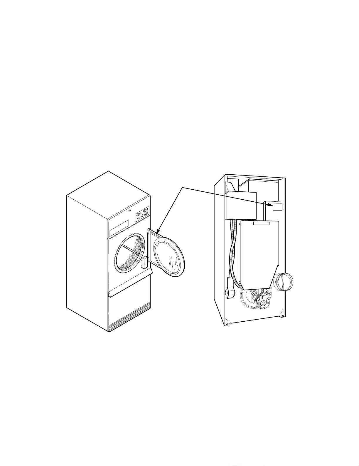
Serial Plate Location
When calling or writing about your product, be sure to
mention model and serial numbers. Model and serial
numbers are found on serial plate on the rear of
machine and inside door.
Wiring Diagram
The wiring diagram is located in the contactor box.
SERIAL
PLATE
TMB803N
6 70269301
© Copyright, Alliance Laundry Systems LLC – DO NOT COPY or TRANSMIT

Safety Warnings and Decals
SAFETY WARNINGS and decals have been provided
in key locations to remind you of important precautions
for the safe operation and maintenance of your tumbler.
Please take the time to review these warnings before
proceeding with service work.
All decals have been designed and applied to withstand
washing and cleaning. Decals should be checked
periodically to be sure they have not been damaged,
removed, or painted. Refer to Parts Manual for
ordering replacement decals.
Safety Precautions for Servicing Tumblers
Prior to servicing tumbler:
• Disconnect electrical service and “lockout” to
prevent unintentional connection.
Section 2 Introduction
• Shut off supply gas valve.
• Allow machine to cool prior to servicing.
After servicing tumbler:
• Control/access panels must be reinstalled.
• Motor/drive/belt guards must be reinstalled.
• Contactor/junction/accessory box covers must be
reinstalled.
• Use a non-corrosive leak detection solution to
check all pipe connections for gas leaks. DO NOT
USE AN OPEN FLAME TO CHECK FOR GAS
LEAKS!
• The loading door switch, lint door switch and
airflow switch must be operating properly.
70269301 7
© Copyright, Alliance Laundry Systems LLC – DO NOT COPY or TRANSMIT
Section 2 Introduction
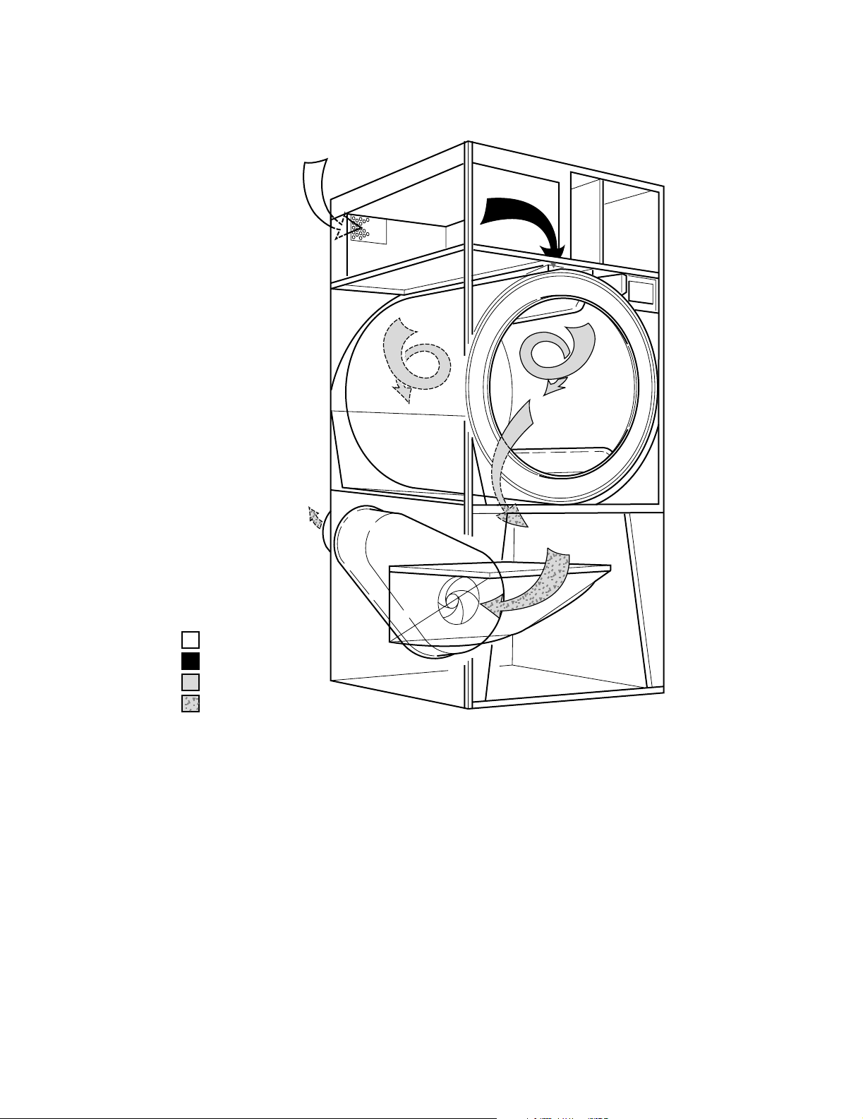
How A Tumbler Works
Fresh Air
Combustion Air
Mixed Air
Exhaust Air
TMB1748S
The tumbler uses heat, air and movement to dry loads of laundry.
When the motor is started, the exhaust fan pulls fresh air in through the air intake and over the heat source (burner
flame for gas, heating element for electric, and coil for steam).
The heated air moves into the cylinder, where it is circulated through the laundry by the tumbling action of the
cylinder.
The air then passes through the lint filter, exhaust fan, and is vented to the outdoors.
8 70269301
© Copyright, Alliance Laundry Systems LLC – DO NOT COPY or TRANSMIT
Section 3
Troubleshooting
WARNING
To reduce the risk of electric shock, fire, explosion, serious injury or death:
• Disconnect electric power to the tumbler before servicing.
• Close gas shut-off valve to gas tumbler before servicing.
• Close steam valve to steam tumbler before servicing.
• Never start the tumbler with any guards/panels removed.
• Whenever ground wires are removed during servicing, these ground wires must be
reconnected to ensure that the tumbler is properly grounded.
IMPORTANT: Refer to appropriate wiring diagram for aid in testing tumbler components.
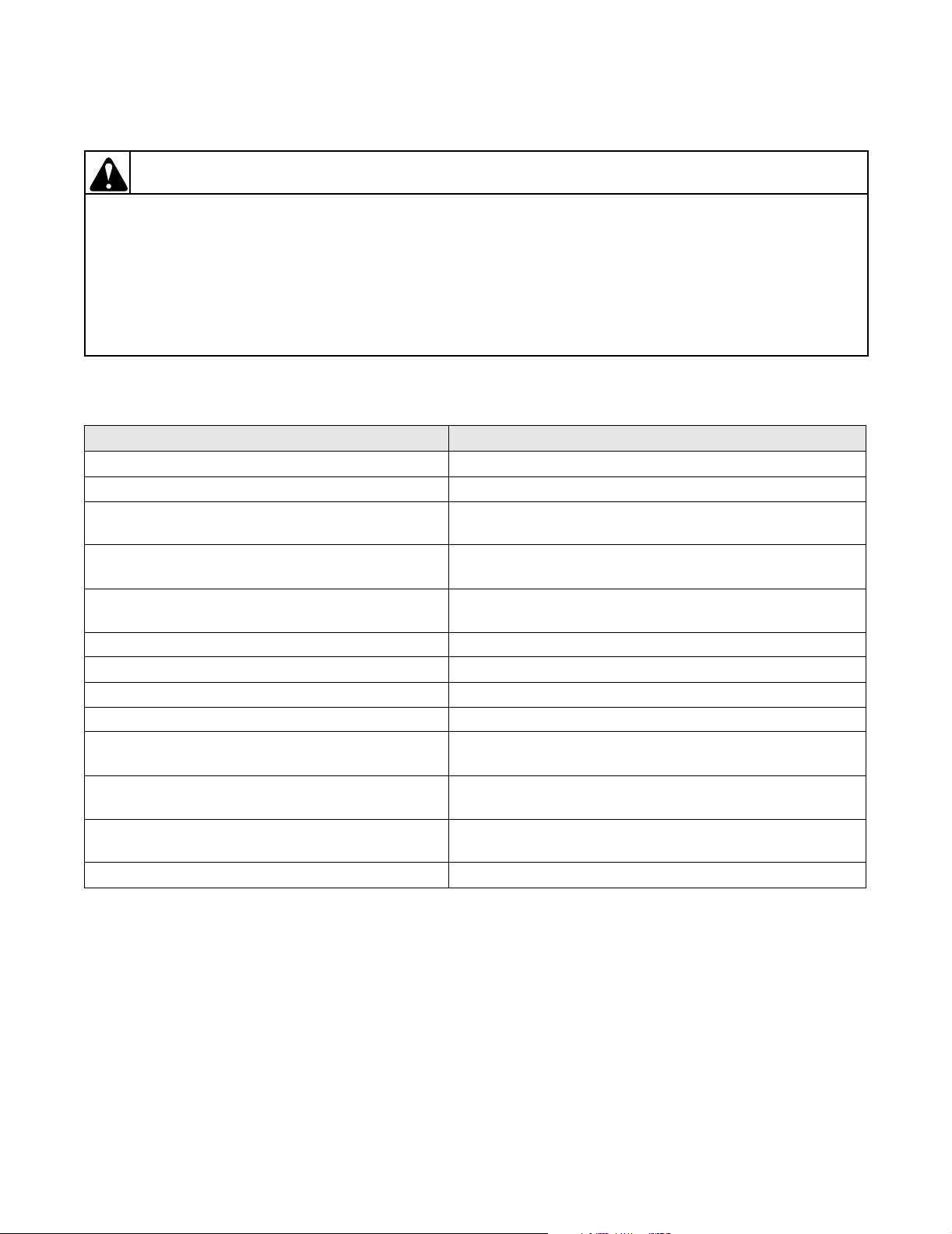
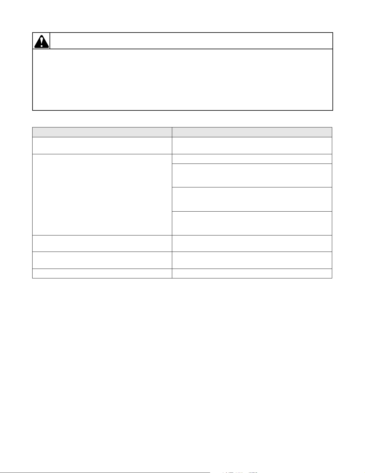
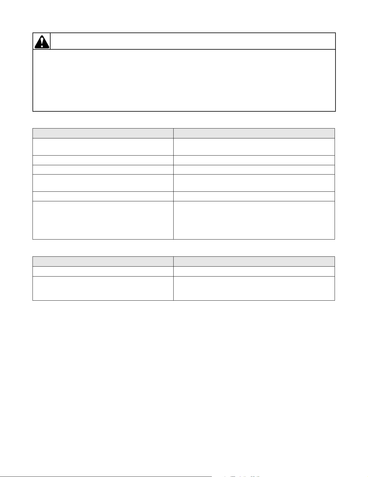
1. MOTOR DOES NOT START
POSSIBLE CAUSE TO CORRECT
Electrical power off or fuses blown. • Check power and fuses. Replace fuses if necessary.
Loading door not closed or inoperative door switch. • Close door, or test switch and replace if inoperative.
Lint door not closed or inoperative lint door switch. • Close lint door, confirm switch is positioned to actuate
with door closed.
Trunnion shaft assembly binding in
trunnion housing bearings.
Start circuit not completed. • Press start switch, or test switch and replace if
Idler shaft binding in idler housing bearings. • Replace bearings.
Inoperative motor. • Have motor tested and replace if inoperative.
Non-Metered Models: Timer improperly set. • Turn drying timer clockwise to desired setting.
Non-Metered Models: Inoperative timer or relay. • Test timer and relay and replace if inoperative.
Metered Models: Improper coins inserted in
accumulator.
Metered Models (CD models): Accumulator knob
improperly set after coins were inserted.
Metered Models (CD models): Inoperative run
switch (accumulator).
Broken, loose, or incorrect wiring. • Refer to wiring diagram located inside contactor box.
• Replace trunnion housing bearings.
inoperative.
• Check that proper coins are inserted.
• Turn knob clockwise to its full limit of travel.
• Test run switch and replace if inoperative.
W002
70269301 9
© Copyright, Alliance Laundry Systems LLC – DO NOT COPY or TRANSMIT
Section 3 Troubleshooting
WARNING
To reduce the risk of electric shock, fire, explosion, serious injury or death:
• Disconnect electric power to the tumbler before servicing.
• Close gas shut-off valve to gas tumbler before servicing.
• Close steam valve to steam tumbler before servicing.
• Never start the tumbler with any guards/panels removed.
• Whenever ground wires are removed during servicing, these ground wires must be
reconnected to ensure that the tumbler is properly grounded.
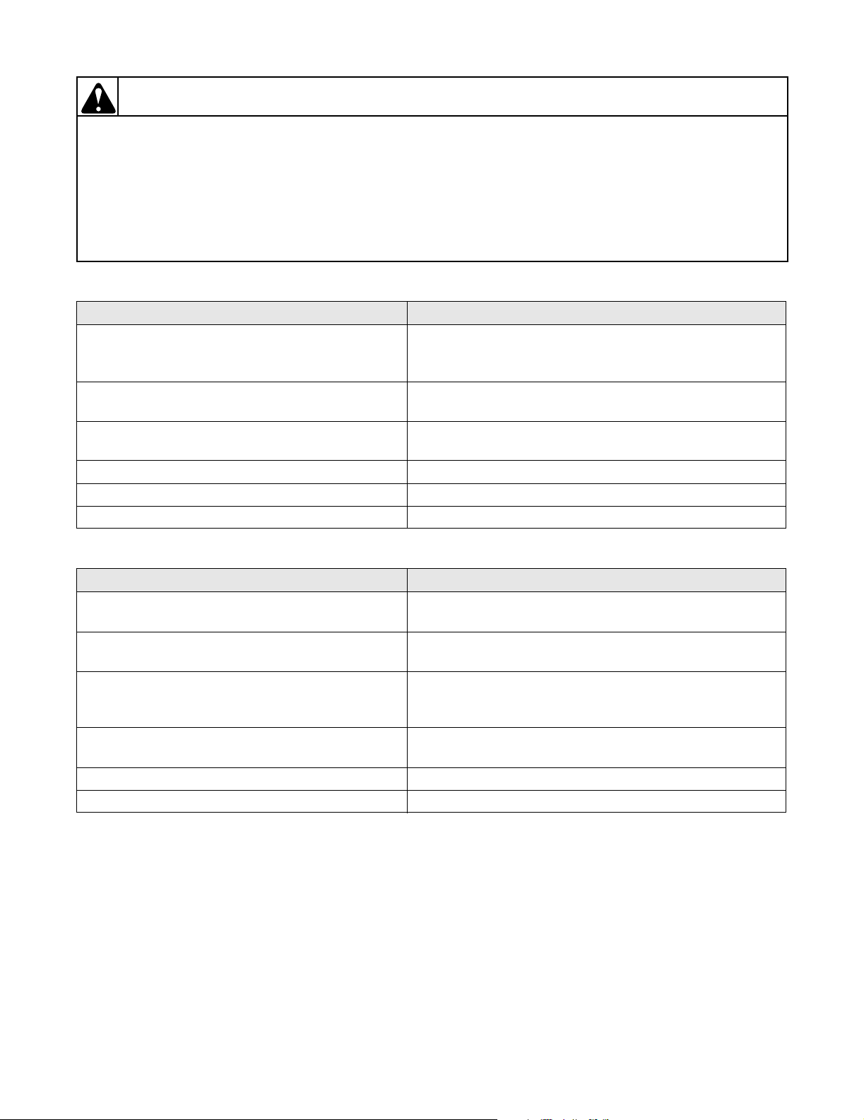
2. MOTOR OVERLOAD PROTECTOR CYCLES REPEATEDLY
POSSIBLE CAUSE TO CORRECT
Incorrect voltage. • Refer to the Installation Manual for electrical
requirements.
Clothes load too large. • Remove part of load.
Clothes cylinder is binding. • Check cylinder for binding. Refer to Adjustment Section
for cylinder adjustment.
Inadequate wiring. • Check with an electrician to ensure that wiring is
adequate.
Inadequate make-up air. • Refer to Installation Manual for make-up air
requirements.
Poor maintenance. • Clean lint accumulation on and around the motor.
Broken, loose, or incorrect wiring. • Refer to wiring diagram located inside contactor box.
W002
3. MOTOR RUNS BUT CYLINDER DOES NOT TURN.
POSSIBLE CAUSE TO CORRECT
Motor drive pulley loose. • Confirm key is in place, tighten setscrews.
Sheave loose. • Confirm key is in place, tighten setscrews and bushing.
Broken or loose belt. • Replace or adjust belt.
Cylinder is binding. • Check cylinder for binding. Refer to Adjustment Section
for proper cylinder adjustment.
Cylinder turn counterclockwise when viewed from
• Switch power leads L1 and L2 to correct rotation.
front of machine. (3 Phase models only)
4. MOTOR DOES NOT STOP
POSSIBLE CAUSE TO CORRECT
Inoperative door switch. • Test switch and replace if inoperative.
Non-Metered Models: Inoperative timer or relay. • Test timer and relay and replace if inoperative.
Metered Models: Inoperative accumulator. • Test accumulator and replace if inoperative.
Incorrect wiring. • Refer to wiring diagram located inside contactor box.
Inoperative motor relay or motor contactor. • Check relay/contactor and replace if inoperative.
10 70269301
© Copyright, Alliance Laundry Systems LLC – DO NOT COPY or TRANSMIT
Section 3 Troubleshooting
WARNING
To reduce the risk of electric shock, fire, explosion, serious injury or death:
• Disconnect electric power to the tumbler before servicing.
• Close gas shut-off valve to gas tumbler before servicing.
• Close steam valve to steam tumbler before servicing.
• Never start the tumbler with any guards/panels removed.
• Whenever ground wires are removed during servicing, these ground wires must be
reconnected to ensure that the tumbler is properly grounded.
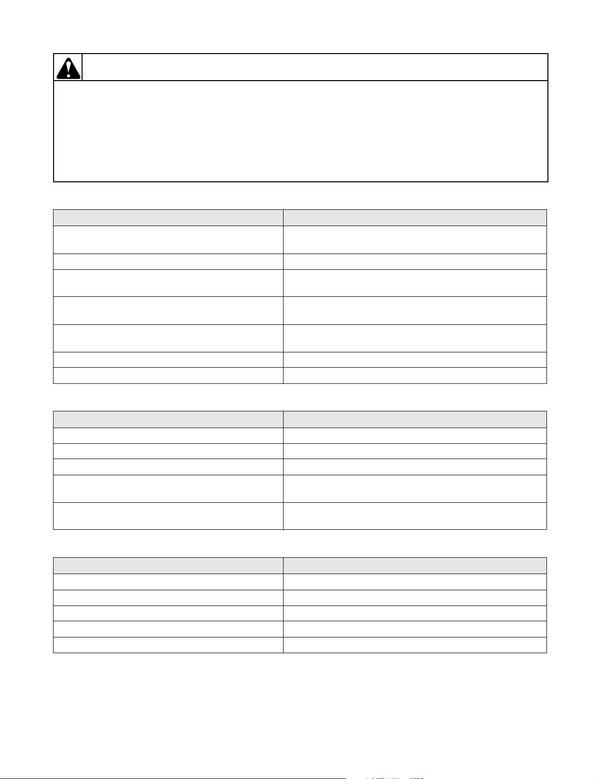
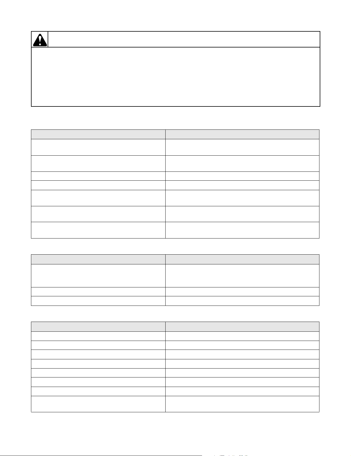
5. HEATING ELEMENT DOES NOT HEAT OR BURNER DOES NOT IGNITE
POSSIBLE CAUSE TO CORRECT
Improper or inadequate exhaust or make-up air
system.
Blown fuses or tripped circuit breakers. • Check fuses or circuit breakers.
Drying timer not selected or inoperative. • Set drying timer or replace if necessary.
“No Heat” selected on control. • Select temperature option.
Inoperative control relay. • Test relay and replace if inoperative.
Inoperative thermistor. • Test thermistor by removing harness from thermistor
Electric Models:
Inoperative heating elements or contactors.
Gas Models:
Insufficient gas supply.
Gas Models:
Incorrect orifices.
Gas Models:
Inoperative gas valve coils.
Gas Models: Inoperative igniter. • Test igniter and replace if inoperative.
Gas Models: Inoperative igniter control. • Test igniter control and replace if inoperative.
• Refer to the Installation Manual for exhaust and make-
up air requirements.
terminals. Check resistance across terminals, should read
approximately 50,000 Ohms at 77°F. Resistance should
decrease with a temperature increase. Replace thermistor
if inoperative.
• Check heat contactors and elements. Replace if necessary.
• Open partially closed gas shut-off valve, or correct low
gas pressure. Check inlet pressure and compare to
pressure specified on serial plate. If pressure cannot be
obtained, contact gas supplier.
• Tumbler is equipped for type of gas specified on serial
plate at 0-2,000 feet altitude. Refer to Installation
Manual.
• Test coils and replace if available as a service part,
otherwise replace valve.
W002
(continued on next page)
70269301 11
© Copyright, Alliance Laundry Systems LLC – DO NOT COPY or TRANSMIT
Section 3 Troubleshooting
WARNING
To reduce the risk of electric shock, fire, explosion, serious injury or death:
• Disconnect electric power to the tumbler before servicing.
• Close gas shut-off valve to gas tumbler before servicing.
• Close steam valve to steam tumbler before servicing.
• Never start the tumbler with any guards/panels removed.
• Whenever ground wires are removed during servicing, these ground wires must be
reconnected to ensure that the tumbler is properly grounded.
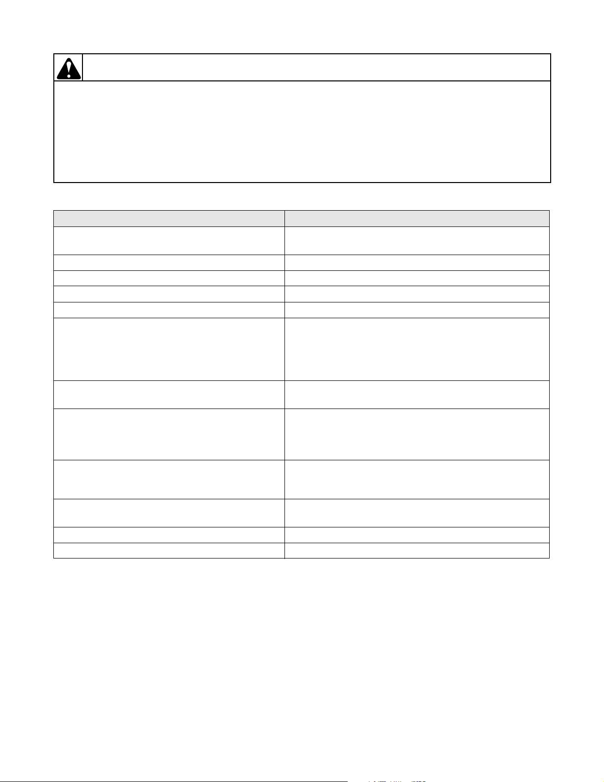
5. HEATING ELEMENT DOES NOT HEAT OR BURNER DOES NOT IGNITE (continued)
POSSIBLE CAUSE TO CORRECT
Gas and Electric Models:
Inoperative high limit thermostat.
Gas and Electric Models:
Inoperative airflow switch.
Gas and Electric Models:
Airflow switch out of adjustment.
Lint door panel not closed properly. • Open lint door panel. Place lint door panel back on
Broken, loose, or incorrect wiring. • Refer to wiring diagram located inside contactor box.
• Test thermostat and replace if inoperative.
• Clean lint compartment after every eight hour shift.
• Check back draft damper for foreign objects, lint
accumulation, or other causes that may prevent damper
from opening.
• Check ductwork for lint build-up. Refer to Installation
Manual to ensure that ductwork and make-up air
openings are sized properly.
• Check exhaust outlet. If a screen has been installed on the
outlet, it may be clogged with lint or frozen over in winter.
NEVER install a screen over the exhaust outlet.
•Refer to Adjustment Section for airflow switch
adjustment.
tumbler ensuring a tight fit.
W002
12 70269301
© Copyright, Alliance Laundry Systems LLC – DO NOT COPY or TRANSMIT
Section 3 Troubleshooting
WARNING
To reduce the risk of electric shock, fire, explosion, serious injury or death:
• Disconnect electric power to the tumbler before servicing.
• Close gas shut-off valve to gas tumbler before servicing.
• Close steam valve to steam tumbler before servicing.
• Never start the tumbler with any guards/panels removed.
• Whenever ground wires are removed during servicing, these ground wires must be
reconnected to ensure that the tumbler is properly grounded.
6. IGNITER DOES NOT SHUT OFF AFTER GAS IGNITION — GAS BURNER
POSSIBLE CAUSE TO CORRECT
Tumbler not properly equipped for type of gas
being used.
• Tumbler is equipped for type of gas specified on serial
plate at 0-2,000 feet altitude. Refer to Installation
Manual.
Insufficient gas supply. • Open partially closed gas shut-off valve, or correct low
gas pressure.
Improperly adjusted burner flame. • Refer to Adjustment Section for recommended burner
flame adjustment.
Electrode assembly incorrectly installed. • Check assembly for correct alignment.
Inoperative igniter control. • Test igniter control and replace if inoperative.
Incorrect wiring. • Refer to wiring diagram located inside contactor box.
W002
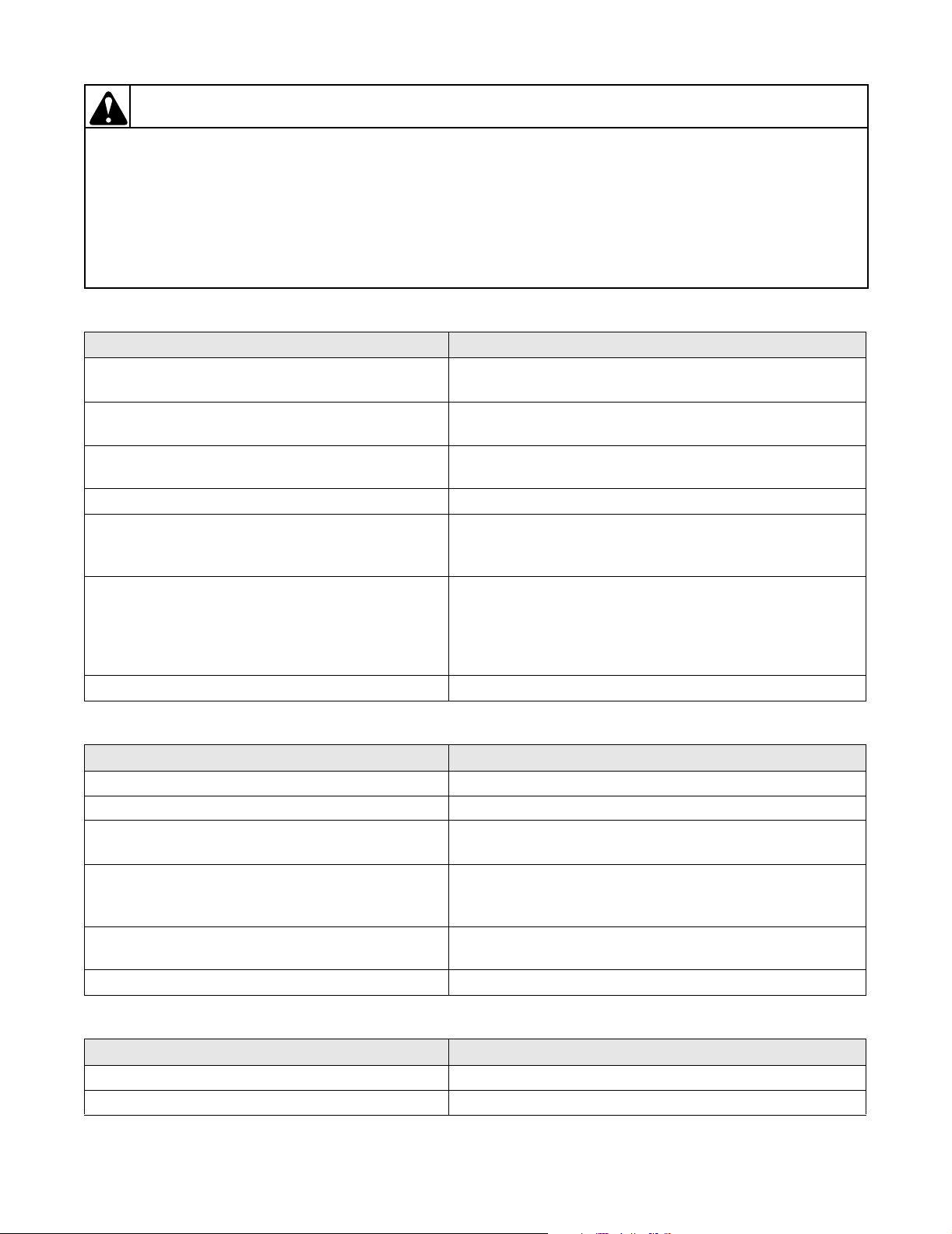
7. HEATING ELEMENT OR BURNER SHUTS OFF PREMATURELY
POSSIBLE CAUSE TO CORRECT
Improper or inadequate exhaust and/or make-up air
system.
Gas Models:
Insufficient gas supply.
Gas Models:
Tumbler not properly equipped for type of gas
used.
Gas Models:
•Refer to Installation Manual for exhaust and make-up air
requirements.
• Open partially closed gas shut-off valve, or correct low
pressure.
• Tumbler is equipped for type of gas specified on serial
plate at 0-2,000 feet altitude. Refer to Installation
Manual.
•Refer to Adjustment Section for burner flame adjustment.
Improperly adjusted burner flame.
Cycling off on high limit thermostat. • Refer to Paragraph 8.
Broken, loose or incorrect wiring. • Refer to wiring diagram located inside contactor box.
70269301 13
© Copyright, Alliance Laundry Systems LLC – DO NOT COPY or TRANSMIT
Section 3 Troubleshooting
WARNING
To reduce the risk of electric shock, fire, explosion, serious injury or death:
• Disconnect electric power to the tumbler before servicing.
• Close gas shut-off valve to gas tumbler before servicing.
• Close steam valve to steam tumbler before servicing.
• Never start the tumbler with any guards/panels removed.
• Whenever ground wires are removed during servicing, these ground wires must be
reconnected to ensure that the tumbler is properly grounded.
8. HEATING ELEMENT OR BURNER REPEATEDLY CYCLES OFF ON HIGH LIMIT
THERMOSTAT
POSSIBLE CAUSE TO CORRECT
External exhaust system is longer than
recommended or inadequate make-up air.
Clogged lint screen. • Remove screen and clean. Lint screen and compartment
Lint in tumbler ducts. • Clean tumbler ducts.
Lint in external exhaust system. • Disassemble exhaust system and clean.
High limit thermostat cycling at too low a
temperature.
Lint door panel not closed properly. • Open lint door panel, place lint door panel back on
Backdraft damper not operating. • Check for foreign objects, lint accumulation or other
•Refer to Installation Manual for exhaust and make-up air
requirements.
should be cleaned after every eight hour shift.
• Replace thermostat.
tumbler ensuring a tight fit.
possible obstructions.
W002
9. HEATING ELEMENT OR BURNER DOES NOT SHUT-OFF
POSSIBLE CAUSE TO CORRECT
Gas Models:
• Replace gas valve.
Impurities on gas valve seat, preventing valve
from closing.
Inoperative drying timer, relay or contactor. • Replace timer, relay or contactor.
Incorrect wiring. • Refer to wiring diagram located inside contactor box.
10. CLOTHES DO NOT DRY
POSSIBLE CAUSE TO CORRECT
Heat source inoperative. • Refer to Paragraph 5.
Too much water in articles being dried. • Remove excess water.
Clothes load too large. • Remove part of load.
Improper or inadequate exhaust system. • Refer to Installation Manual for exhaust requirements.
Heat source shuts-off prematurely. • Refer to Paragraph 7.
Drying timer improperly set. • Set selector for higher setting.
Incorrect voltage. • Refer to Installation Manual for electrical requirements.
Inadequate make-up air. • Refer to Installation Manual for make-up air
requirements.
14 70269301
© Copyright, Alliance Laundry Systems LLC – DO NOT COPY or TRANSMIT
Section 3 Troubleshooting
WARNING
To reduce the risk of electric shock, fire, explosion, serious injury or death:
• Disconnect electric power to the tumbler before servicing.
• Close gas shut-off valve to gas tumbler before servicing.
• Close steam valve to steam tumbler before servicing.
• Never start the tumbler with any guards/panels removed.
• Whenever ground wires are removed during servicing, these ground wires must be
reconnected to ensure that the tumbler is properly grounded.
11. TUMBLER OVERHEATING
POSSIBLE CAUSE TO CORRECT
Gas Models:
Incorrect main burner orifices.
Gas Models:
• Replace orifices. Refer to the Installation Manual for
burner orifice requirements.
• Gas pressure must be as specified on serial plate.
Gas pressure too high.
Inadequate make-up air. • Refer to Installation Manual for make-up air
requirements.
Lint accumulation. • Remove lint.
Restricted or inadequate exhaust system. • Remove obstruction or lint build-up from exhaust
ductwork. Refer to the Installation Manual for exhaust
system requirements.
Inoperative thermistor. • Test thermistor by removing harness from thermistor
terminals. Check resistance across terminals, should read
approximately 50,000 Ohms at 77°F. Resistance should
decrease with a temperature increase. Replace thermistor
if inoperative.
Inoperative cabinet limit or burner limit thermostat. • Check thermostats with Ohm meter and replace if open.
W002
12. BURNERS NOT BURNING PROPERLY — GAS MODELS
POSSIBLE CAUSE TO CORRECT
Burner air shutters incorrectly adjusted. • Refer to Adjustment Section for proper flame adjustment.
Dirt in burners. • Disassemble burners and blow out the dirt.
Gas pressure too high or too low. • Check serial plate on back of the tumbler for correct gas
pressure.
Incorrect orifices. • Tumbler is equipped for type of gas specified on serial
plate at 0-2,000 feet altitude. Refer to Installation
Manual.
Make-up air inadequate or pressured. • Refer to Installation Manual for proper make-up air
requirements.
Restricted or blocked exhaust duct. • Disassemble and clean exhaust system.
13. LOADING DOOR OPENS DURING OPERATION
POSSIBLE CAUSE TO CORRECT
Door strike improperly adjusted. • Refer to Adjustment Section for door strike adjustment.
Tumbler improperly leveled. • Refer to Adjustment Section for leveling leg adjustment.
70269301 15
© Copyright, Alliance Laundry Systems LLC – DO NOT COPY or TRANSMIT
Section 3 Troubleshooting
WARNING
To reduce the risk of electric shock, fire, explosion, serious injury or death:
• Disconnect electric power to the tumbler before servicing.
• Close gas shut-off valve to gas tumbler before servicing.
• Close steam valve to steam tumbler before servicing.
• Never start the tumbler with any guards/panels removed.
• Whenever ground wires are removed during servicing, these ground wires must be
reconnected to ensure that the tumbler is properly grounded.
14. TUMBLER RUNS BUT NO STEAM TO COILS — STEAM MODELS
POSSIBLE CAUSE TO CORRECT
Valves closed. • Check all valves in supply and return lines, make sure
they are open.
Blocked steam trap. • Remove trap and clean. Replace if inoperative.
Inoperative solenoid valve. • Check operation of solenoid valve.
Incorrect installation of check valve. • Check for inlet and outlet markings on check valve, and
invert if necessary.
Clogged strainer. • Remove strainer and clean.
Inoperative timer or thermistor. • Test timer. Test thermistor by removing harness from
thermistor terminals. Check resistance across terminals,
should read approximately 50,000 Ohms at 77°F.
Resistance should decrease with a temperature increase.
Replace either if inoperative.
W002
15. WATER IN STEAM LINE — STEAM MODELS
POSSIBLE CAUSE TO CORRECT
Incorrect installation of steam piping. • Refer to Installation Manual for steam requirements.
Trap functioning improperly. • Check trap for size and capacity. If trap is dirty or sluggish
clean thoroughly or replace. Check return line for high
back pressure.
16 70269301
© Copyright, Alliance Laundry Systems LLC – DO NOT COPY or TRANSMIT
Section 3 Troubleshooting
WARNING
To reduce the risk of electric shock, fire, explosion, serious injury or death:
• Disconnect electric power to the tumbler before servicing.
• Close gas shut-off valve to gas tumbler before servicing.
• Close steam valve to steam tumbler before servicing.
• Never start the tumbler with any guards/panels removed.
• Whenever ground wires are removed during servicing, these ground wires must be
reconnected to ensure that the tumbler is properly grounded.
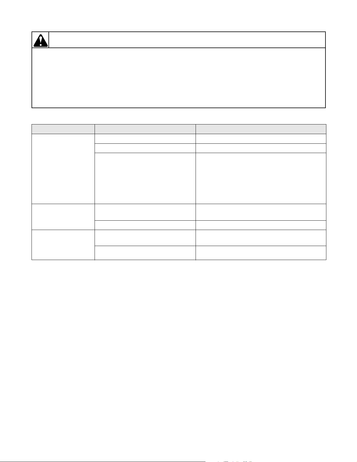
16. TROUBLESHOOTING ELECTRONIC CONTROL MODELS
PROBLEM POSSIBLE CAUSE TO CORRECT
Door Open light and
display flash with door
closed
Display shows “SH”
and signals sounds
Display shows “OP”
and signal sounds
three minutes after
tumbler is started
Door switch faulty. Replace door switch.
Lint panel switch faulty. Replace lint panel switch.
Electrical service connected
incorrectly.
Check service connections to terminal block in
junction box. For 120 or 240 Volt tumblers,
neutral wire must be connected to terminal
marked “NEUT”. On single phase tumblers, hot
wire must be connected to terminal marked “L1”.
A ground wire must be secured to the ground
screw in the junction box.
Temperature at sensor is over 191°F
(88.3°C).
Allow tumbler to cool and press ON/SELECT
pad. If display still shows “SH”, replace sensor.
Temperature sensor shorted. Replace temperature sensor.
Temperature at sensor is under 24°F
(-4.4°C).
If the temperature of the tumbler is above 24°F
(-4.4°C), replace temperature sensor.
Temperature sensor open. Replace temperature sensor.
W002
70269301 17
© Copyright, Alliance Laundry Systems LLC – DO NOT COPY or TRANSMIT
Section 3 Troubleshooting
WARNING
To reduce the risk of electric shock, fire, explosion, serious injury or death:
• Disconnect electric power to the tumbler before servicing.
• Close gas shut-off valve to gas tumbler before servicing.
• Close steam valve to steam tumbler before servicing.
• Never start the tumbler with any guards/panels removed.
• Whenever ground wires are removed during servicing, these ground wires must be
reconnected to ensure that the tumbler is properly grounded.
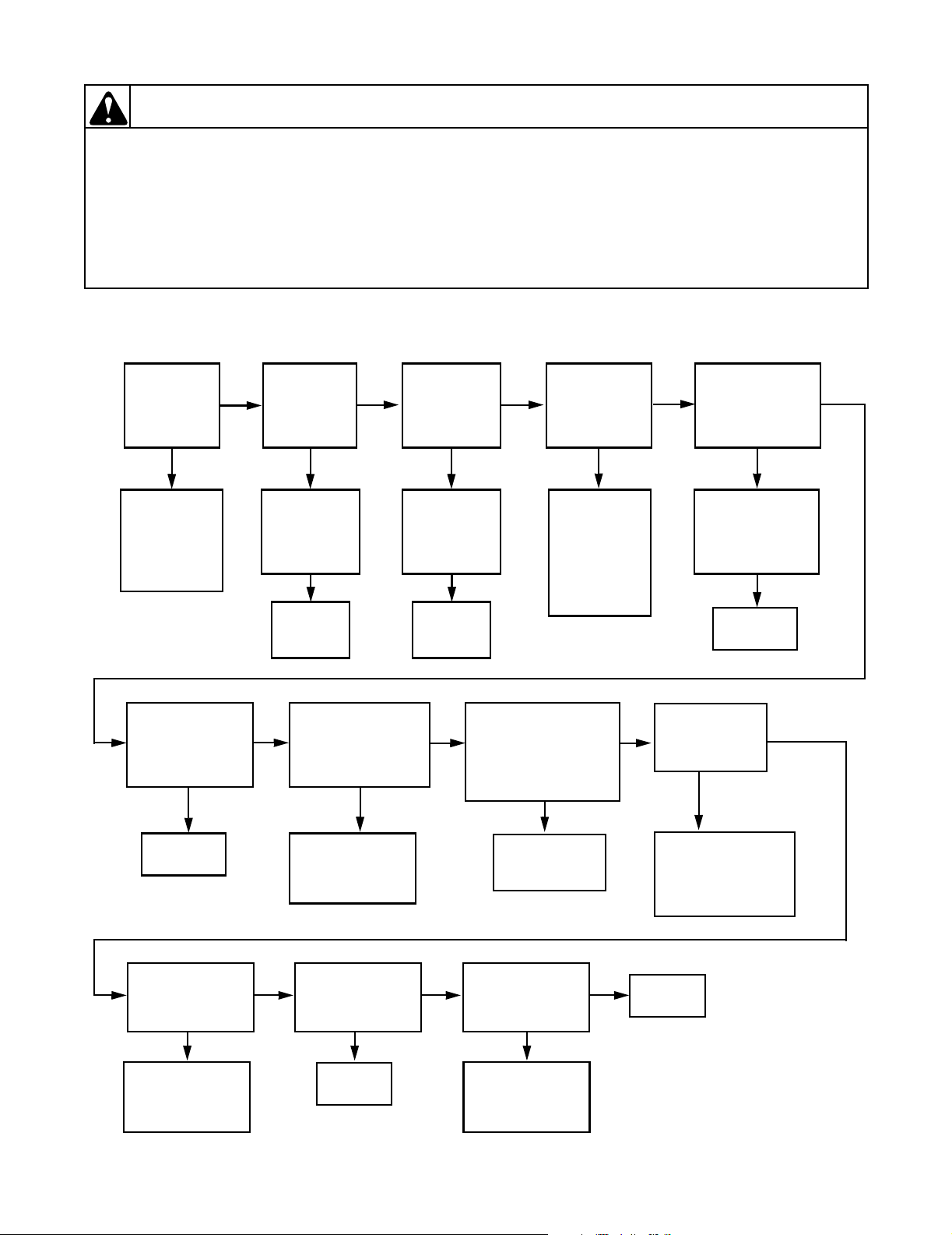
17. TUMBLER WILL NOT START, TIME ON DRYING TIMER, DOOR CLOSED
(Manual Timer Models)
W002
CHECK FOR
24 VOLTS
INTO
DOOR
SWITCH
NO
CHECK
ELECTRICAL
SERVICE
TO TUMBLER
(Transformer/
Fuses)
CHECK FOR
24 VOLTS ON
TERMINAL 5 OF
CONTROL RELAY
NO
REPLACE
RELAY
CHECK FOR
24 VOLTS
OUT OF
DOOR
SWITCH
HAS
DOOR SWITCH
BEEN
ACTUATED?
REPLACE
DOOR
SWITCH
YES YE S YES
PUSH-TO-START
BROKEN WIRE
FROM CONTROL
RELAY TERMINAL 5
YES
NO NO
YES
CHECK FOR
24 VOLTS INTO
SWITCH
CHECK FOR
CHECK FOR
24 VOLTS
OUT OF
LINT PANEL
SWITCH
HAS
LINT PANEL
SWITCH
BEEN
ACTUATED?
REPLACE
LINT PANEL
SWITCH
NO NO
YES
NO
YES
PUSH-TO-START
SWITCH. CHECK FOR
24 VOLTS OUT
OF PUSH-TO-START
PUSH-TO-START
CHECK FOR
24 VOLTS AT
TERMINAL 3 OF
CONTROL
RELAY
CHECK
LINT PANEL
SWITCH FOR
BROKEN WIRE
OR POOR
CONNECTION
AT HARNESS
PLUG
PRESS
SWITCH
REPLACE
SWITCH
CHECK FOR
YESYES
CHECK FOR
24 VOLTS TO
MOTOR RELAY
BROKEN WIRE
CONNECTION
AT HARNESS PLUG
24 VOLTS
ACROSS COIL
TERMINALS OF
CONTROL RELAY
CHECK FOR
24 VOLTS ON
TERMINAL B
OF DRYING TIMER
REPLACE
TIMER
COIL
NO
CHECK FOR
OR POOR
YES
NO
NO
YES
CHECK FOR
LINE VOLTAGE
IN AND OUT OF
RELAY
NO
CHECK POWER
SUPPLY TO
TUMBLER AND
WIRES TO RELAY
YES
18 70269301
CHECK MOTOR
CONNECTIONS
PER WIRING
DIAGRAM
NO
CORRECT
WIRING
© Copyright, Alliance Laundry Systems LLC – DO NOT COPY or TRANSMIT
YES
CHECK FOR
LINE VOLTAGE
AT MOTOR
TERMINALS
NO
CHECK
CONNECTIONS
AND HARNESS
CONTINUITY
YES
REPLACE
MOTOR
 Loading...