

Page 1

Washer-Extractor
Refer to Page 5 for Model Numbers
Parts
www.alliancelaundry.com
Part No. D0073R9
May 2017
Page 2

Page 3

Table of Contents
Title Page
Parts Ordering Information........................................................................................................................................ 3
Serial Plate Location ................................................................................................................................................. 3
Model Identification ................................................................................................................................................... 5
Washer-Extractor Product Overview......................................................................................................................... 6
MDP100 and MDP300 Drain Plumbing (Drawing 1 of 3) .......................................................................................... 8
MDP100 and MDP300 Drain Plumbing (Drawing 2 of 3) ........................................................................................ 10
MDP100 and MDP300 Drain Plumbing (Drawing 3 of 3) ........................................................................................ 12
MDP90 Drain Plumbing .......................................................................................................................................... 14
Drain Valve - 2 Inch with Lid ................................................................................................................................... 16
MDP100 Drain Valve - Normally Open ................................................................................................................... 18
MDP100 Drain Valve - Normally Closed ................................................................................................................. 20
MDP300 Drain Valve - Normally Open ................................................................................................................... 22
MDP300 Drain Valve - Normally Closed ................................................................................................................. 24
MDP90 Drain Valve - Normally Open .................................................................................................................... 26
MDP90 Drain Valve - Normally Closed ................................................................................................................... 28
Upper Back Panel ................................................................................................................................................... 30
Water Inlet Valves ................................................................................................................................................... 32
Water Inlet Valves - Invesys ................................................................................................................................... 34
Water Inlet Valves - Elbi and Techno...................................................................................................................... 36
Water Inlet Valves - Techno.................................................................................................................................... 38
PB2 Supply Dispenser - Models Through 12/31/1991 ............................................................................................ 40
PB3 Supply Dispenser - Models Starting 1/1/1992 ................................................................................................. 42
Control Panel - Ram Stetter .................................................................................................................................... 44
Control Panel - Fiber ............................................................................................................................................... 46
Control Panel - 10 Button........................................................................................................................................ 48
Control Panel - PLC9 OPL ...................................................................................................................................... 50
Control Panel - PLC9 Coin...................................................................................................................................... 52
Control Panel - PC20 and PC30 ............................................................................................................................. 54
Control Panel - Micro-20 ......................................................................................................................................... 56
Control Panel Decals - 10 Button............................................................................................................................ 58
Electrical Component Mounting Plate - Boiler Fed or Steam Heat Models............................................................. 60
Electrical Component Mounting Plate - Ram Stetter Control.................................................................................. 62
Electrical Component Mounting Plate - Fiber Control ............................................................................................. 64
Electrical Component Mounting Plate - 10 Button Control...................................................................................... 66
Electrical Component Mounting Plate - PC30 Control ............................................................................................ 68
Door Lock (Drawing 1 of 4) ..................................................................................................................................... 70
Door Lock (Drawing 2 of 4) ..................................................................................................................................... 72
Door Lock (Drawing 3 of 4) ..................................................................................................................................... 74
Door Lock (Drawing 4 of 4) ..................................................................................................................................... 76
Door Handle ............................................................................................................................................................ 78
Door ........................................................................................................................................................................ 80
© Copyright 2017, Alliance Laundry Systems LLC
All rights reserved. No part of the contents of this book may be reproduced or transmitted in any form or by any
means without the expressed written consent of the publisher.
D0073
© Copyright, Alliance Laundry Systems LLC – DO NOT COPY or TRANSMIT
1
Page 4

Shell and Basket ..................................................................................................................................................... 82
Tub.......................................................................................................................................................................... 84
Bearing Housing ..................................................................................................................................................... 86
Pulley and Belt ........................................................................................................................................................ 88
Top and Back Panels .............................................................................................................................................. 90
Front and Side Panels ............................................................................................................................................ 92
Supply Dispenser Cover ......................................................................................................................................... 94
Motor....................................................................................................................................................................... 96
Inverter Drive .......................................................................................................................................................... 98
Frame.................................................................................................................................................................... 100
Coin Vault ............................................................................................................................................................. 102
Transformer, Motor Thermal Protector and Program Indicator ............................................................................. 104
Coin Meter ............................................................................................................................................................ 106
Capacitor, Coin Meter and Heating Element Plug ................................................................................................ 108
Parts Index ............................................................................................................................................................ 111
2
© Copyright, Alliance Laundry Systems LLC – DO NOT COPY or TRANSMIT
D0073
Page 5

Parts Ordering Information
If literature or replacement parts are required, contact the source from whom the machine was purchased or contact Alliance Laundry Systems at
(920) 748-3950 for the name and address of the
nearest authorized parts distributor.
Serial Plate Location
When calling or writing about your product, be
sure to mention model and serial numbers. Model
and serial numbers are located on serial plate(s).
For technical assistance, call the number listed
below:
(920) 748-3121 Ripon, Wisconsin
D0073
© Copyright, Alliance Laundry Systems LLC – DO NOT COPY or TRANSMIT
3
Page 6

Notes
4
© Copyright, Alliance Laundry Systems LLC – DO NOT COPY or TRANSMIT
D0073
Page 7

Model Identification
Information in this manual is applicable to these washer-extractor models:
CWE030AN2
CWE030MC2
CWE030MD2
CWE030ME2
CWE030ML2
CWE030MN2
CWE030MX2
CWE030MY2
CWE035AN2
CWE035MC2
CWE035MD2
CWE035ME2
CWE035ML2
CWE035MN2
CWE035MX2
CWE035MY2
CWE132AN2
CWE132MC2
CWE132MD2
CWE132ME2
CWE132ML2
CWE132MN2
CWE132MX2
CWE132MY2
CWE165AN2
CWE165MC2
CWE165MD2
CWE165ME2
CWE165ML2
CWE165MN2
CWE165MX2
CWE165MY2
IWE030AN2
IWE030MC2
IWE030MD2
IWE030ME2
IWE030MN2
IWE030MX2
IWE030MY2
IWE030SC2
IWE030SD2
IWE030SE2
IWE030SL2
IWE030SR2
IWE030SX2
IWE030SY2
IWE035AN2
IWE035MC2
IWE035MD2
IWE035ME2
IWE035ML2
IWE035MN2
IWE035MX2
IWE035MY2
IWE035SC2
IWE035SD2
IWE035SE2
IWE035SL2
IWE035SR2
IWE035SX2
IWE035SY2
IWE132AN2
IWE132MC2
IWE132MD2
IWE132ME2
IWE132ML2
IWE132MN2
IWE132MX2
IWE132MY2
IWE132SC2
IWE132SD2
IWE132SE2
IWE132SL2
IWE132SR2
IWE132SX2
IWE132SY2
IWE165AN2
IWE165MC2
IWE165MD2
IWE165ME2
IWE165ML2
IWE165MN2
IWE165MX2
IWE165MY2
IWE165SC2
IWE165SD2
IWE165SE2
IWE165SL2
IWE165SR2
IWE165SX2
IWE165SY2
WE110_CAM-TIMER
WE110_CYGNUS-PRO
WE110_MICRO-20
WE110_MICRO-9
WE110_PC30
WE110_PS40
WE110_PS40F
WE110_SIGMA
WE132_CAM-TIMER
WE132_CYGNUS-PRO
WE132_MICRO-20
WE132_MICRO-9
WE132_PC30
WE132_PS40
WE132_PS40F
WE132_SIGMA
WE165_CAM-TIMER
WE165_CYGNUS-PRO
WE165_MICRO-20
WE165_MICRO-9
WE165_PC30
WE165_PS40
WE165_PS40F
WE165_SIGMA
D0073
© Copyright, Alliance Laundry Systems LLC – DO NOT COPY or TRANSMIT
5
Page 8
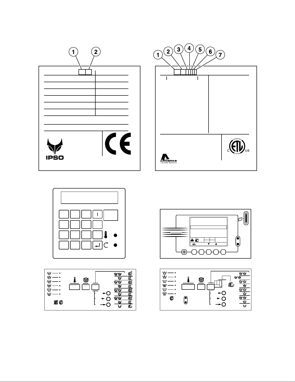
Washer-Extractor Product Overview
CFD310P_D0073
PS40
Micro 20 Sigma
Cygnus Professional
Label 1 Label 2
CYGNUS
PROFESSIONAL
Norm al wash 40º-40ºC
War m was h 40º-60ºC
Hot w ash 40º-90ºC
Delicate 1 90ºC
Synthetic 1
1000
40ºC
1h03
Micro20 Controlled
1
2
3
4
5
6
7
8
9
SELECT
START
ECO.
P
I
E
Sigma Controlled
SELECT
ABDC
START
ECO.
P
I
E
1
2
3
4
5
6
7
8
9
1 2 3
PS40
4 5 6O
7 8 9NO
PROG
+ 0
_
Alliance International BVBA
Made in Belgium
TEL 1-920-748-3121
www.comlaundry.com
100740
CONFORMS TO ANSI/UL
STD 2157
CERTIFIED TO CAN/CSA
STD C22.2 NO.169-94
IPX4
Model No: IW E 0 30 M C2 X 10 U 01
Volts Hertz:
Phase:
Amps:
Recommended
Circuit Breaker:
Interrupt Current:
Motor:
Elec Heat:
Steam
heat:
Serial No: 0 7 1 0W D 01 5 2
208-240 50/60
1 - 3
6 amps
15 amps
10 kA
1 hp
0,75 kW
N/A kW
N/A psi
N/A bar
Type:
Capacity:
Water
Pressure:
Max Speed:
Net
Weight:
WFF75
18/ 7 lbs/kg
30-85 psi
2.07-5.86 bar
700 rpm
400 lbs
181 kg
Alliance International BVBA
Nieuwstraat 146
8560 Wevelgem
Belgium
Tel: +32 56 41 20 54
Fax: +32 56 41 86 74
www.ipso.be
WE132C
3 ~ 400V 50Hz
0.55kW 2.5A
9kW 16A
9.55 kW
592 Nm
2007
Type:
Voltage:
Motor:
Heating:
To ta l :
Kinetic energy:
Manufactured in:
sfc 741837
Water Pressure:
min. 2.07 max. 5.86 Kg/cm²
min. 20.7 max. 58.6 N/cm²
IPX4
07110WD0339
181 kg
73 L
7,3 kg
530 mm
700 rpm
Nr:
Weight:
Capacity:
Dry Load:
Drum:
Speed:
6
© Copyright, Alliance Laundry Systems LLC – DO NOT COPY or TRANSMIT
D0073
Page 9

Washer-Extractor Product Overview
REF PART NO. DESCRIPTION COMMENTS
1 -Product Family CWE
IWE
WE
2 - Capacity 030
035
110
132
165
3 - Control A (PS40F)
CAM-Timer
Cygnus-Pro
Micro-9
M (Micro-20)
PC30
PS40
S (Sigma)
4 - Actuation C (Coin Drop Meter)
D (Dual Coin Drop)
E (Electronic Drop)
L (Prep for Remote or Central Pay)
N (Non-Coin)
R (Smart Card Ready)
X (Prep for Coin)
Y (Card Ready)
5 - Speed 2 (Normal Spin)
6 - Voltage N (440-480/50-60/3/3)
P (380-415/50-60/3/3)
Q (208-240/50-60/3/3)
X (200-240/50-60/1/3)
7 -Design 1
D0073
© Copyright, Alliance Laundry Systems LLC – DO NOT COPY or TRANSMIT
7
Page 10
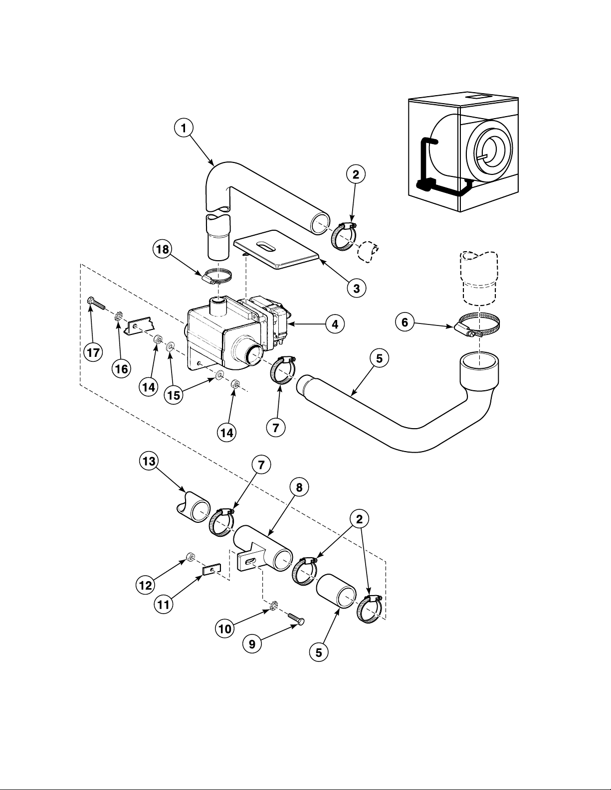
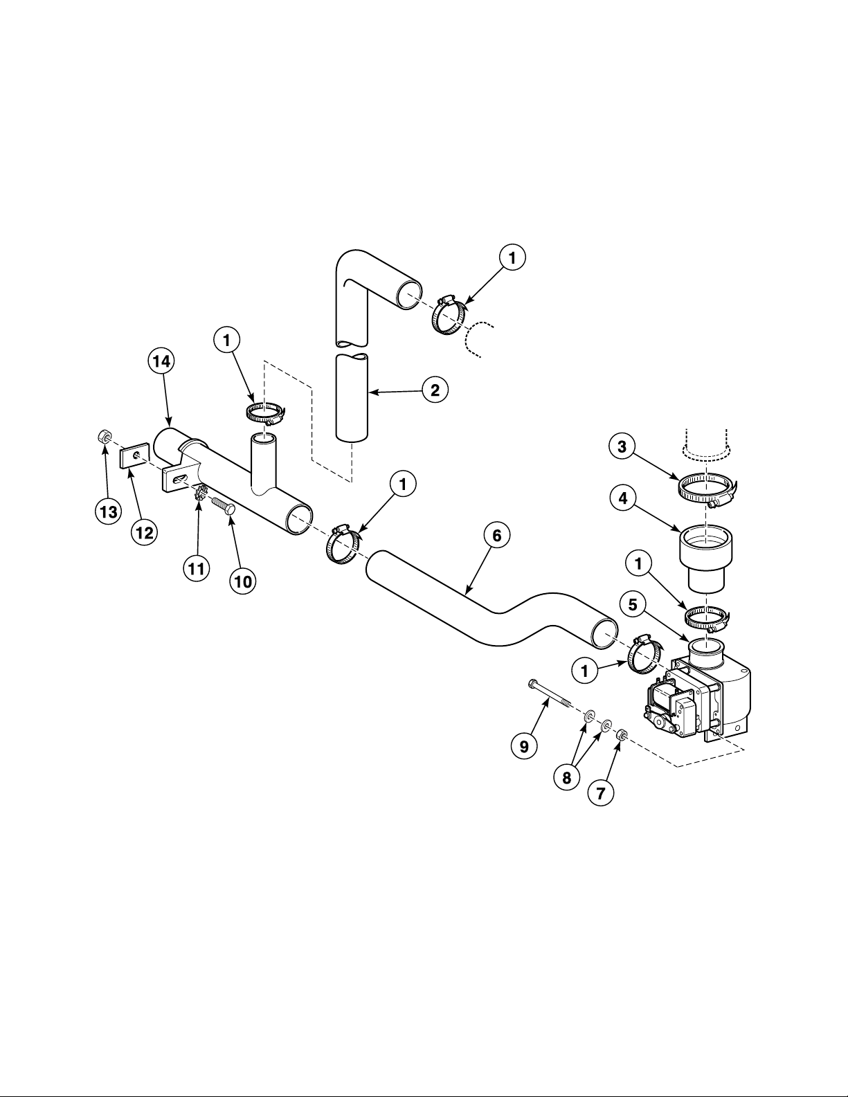
MDP100 and MDP300 Drain Plumbing (Drawing 1 of 3)
BE100067P_D0073
Water Level Sensor on Tub; Overflow Through Drain Valve
8
© Copyright, Alliance Laundry Systems LLC – DO NOT COPY or TRANSMIT
D0073
Page 11

MDP100 and MDP300 Drain Plumbing (Drawing 1 of 3)
REF PART NO. DESCRIPTION COMMENTS
1 223/00130/00 Overflow Hose Must be cut to necessary length
2 223/00013/00 Hose Clamp
3 113/00026/00 Drain Valve Covering
4 209/00203/00 Drain Valve 24 Volt/50 Hertz; NO
4 209/00052/00 Drain Valve 115 Volt/60 Hertz; NO
4 209/00051/00 Drain Valve 240 Volt/50 or 60 Hertz; NO; MDP100
4 B12630701 Drain Valve Kit 240 Volt/50 or 60 Hertz; NO; MDP300
4 209/00115/00 Drain Valve 240 Volt/50 or 60 Hertz; NC; MDP100
4 209/00171/00 Drain Valve 240 Volt/50 or 60 Hertz; NC; MDP300
5 223/00046/00 Drain Hose MDP100
5 223/00072/00 Drain Hose MDP300
6 223/00014/00 Hose Clamp
7 223/00013/00 Hose Clamp MDP100
7 223/00057/00 Clamp MDP300
8 223/00025/00 Outlet Pipe
9 206/00014/00 Bolt
10 203/00004/00 Washer
11 101/00007/00 Outlet Pipe Plate Assembly
12 204/00005/00 Nut
13 223/00054/00 Drain Elbow MDP100
13 223/00056/00 Drain Elbow MDP300
14 204/00004/00 Bolt
15 202/00002/00 Washer
16 203/00003/00 Washer
17 206/00010/00 Bolt
18 223/00012/00 Hose Clamp
D0073
© Copyright, Alliance Laundry Systems LLC – DO NOT COPY or TRANSMIT
9
Page 12
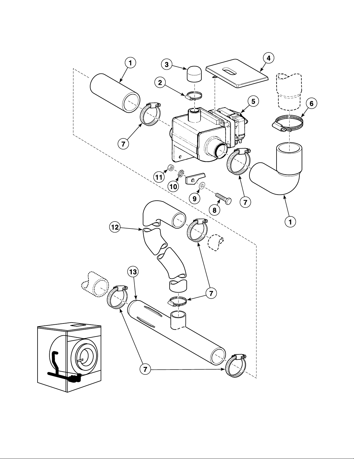
MDP100 and MDP300 Drain Plumbing (Drawing 2 of 3)
BE100068P_D0073
Water Level Sensor on Tub; No Overflow Through Drain Valve
10
© Copyright, Alliance Laundry Systems LLC – DO NOT COPY or TRANSMIT
D0073
Page 13

MDP100 and MDP300 Drain Plumbing (Drawing 2 of 3)
REF PART NO. DESCRIPTION COMMENTS
1 223/00112/00 Exhaust Valve
2 223/00012/00 Hose Clamp
3 223/00086/00 Drain Valve Overflow Plug
4 113/00026/00 Drain Valve Covering
5 209/00203/00 Drain Valve 24 Volt/50 Hertz; NO
5 209/00052/00 Drain Valve 115 Volt/60 Hertz; NO
5 209/00051/00 Drain Valve 240 Volt/50 or 60 Hertz; NO; MDP100
5 B12630701 Drain Valve Kit 240 Volt/50 or 60 Hertz; NO; MDP300
5 209/00115/00 Drain Valve 240 Volt/50 or 60 Hertz; NC; MDP100
5 209/00171/00 Drain Valve 240 Volt/50 or 60 Hertz; NC; MDP300
6 223/00014/00 Hose Clamp
7 223/00013/00 Hose Clamp
8 206/00010/00 Bolt
9 202/00002/00 Washer
10 203/00003/00 Washer
11 204/00004/00 Bolt
12 223/00111/00 Overflow Pipe
13 223/00105/00 Drain Pipe
D0073
© Copyright, Alliance Laundry Systems LLC – DO NOT COPY or TRANSMIT
11
Page 14
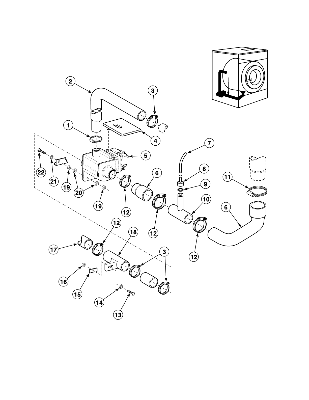
MDP100 and MDP300 Drain Plumbing (Drawing 3 of 3)
BE100069P_D0073
Water Level Sensor on Drain; Overflow Through Drain Valve
12
© Copyright, Alliance Laundry Systems LLC – DO NOT COPY or TRANSMIT
D0073
Page 15

MDP100 and MDP300 Drain Plumbing (Drawing 3 of 3)
REF PART NO. DESCRIPTION COMMENTS
1 223/00012/00 Hose Clamp
2 223/00130/00 Overflow Hose Must be cut to necessary length
3 223/00013/00 Hose Clamp
4 113/00026/00 Drain Valve Covering
5 209/00203/00 Drain Valve 24 Volt/50 Hertz; NO
5 209/00052/00 Drain Valve 115 Volt/60 Hertz; NO
5 209/00051/00 Drain Valve 240 Volt/50 or 60 Hertz; NO; MDP100
5 B12630701 Drain Valve Kit 240 Volt/50 or 60 Hertz; NO; MDP300
5 209/00115/00 Drain Valve 240 Volt/50 or 60 Hertz; NC; MDP100
5 209/00171/00 Drain Valve 240 Volt/50 or 60 Hertz; NC; MDP300
6 223/00046/00 Drain Hose MDP100
6 223/00072/00 Drain Hose MDP300
7 223/00036/00 Pressure Hose
8 223/00035/02 Pressure Switch Cap
9 223/00035/03 O-Ring
10 223/00083/00 Pressure Hose
10 223/00035/01 Hose Tee
11 223/00014/00 Hose Clamp
12 223/00013/00 Hose Clamp MDP100
12 223/00057/00 Clamp MDP300
13 206/00014/00 Bolt
14 203/00004/00 Washer
15 101/00007/00 Outlet Pipe Plate Assembly
16 204/00005/00 Nut
17 223/00054/00 Drain Elbow MDP100
17 223/00056/00 Drain Elbow MDP300
18 223/00025/00 Outlet Pipe
19 204/00004/00 Bolt
20 202/00002/00 Washer
21 203/00003/00 Washer
22 206/00010/00 Bolt
D0073
© Copyright, Alliance Laundry Systems LLC – DO NOT COPY or TRANSMIT
13
Page 16
MDP90 Drain Plumbing
BE100070P_D0073
14
© Copyright, Alliance Laundry Systems LLC – DO NOT COPY or TRANSMIT
D0073
Page 17

MDP90 Drain Plumbing
REF PART NO. DESCRIPTION COMMENTS
1 223/00013/00 Hose Clamp
2 223/00111/00 Overflow Pipe
3 223/00014/00 Hose Clamp
4 223/00116/00 Tub Drain Exhaust Valve
5 209/00256/00 Drain Valve NO
5 209/00292/00 Exhaust Valve NC
6 223/00145/00 Valve
7 204/00109/00 Nut
8 202/00002/00 Washer
9 206/00068/00 Bolt
10 206/00014/00 Bolt
11 203/00004/00 Washer
12 101/00007/00 Outlet Pipe Plate Assembly
13 204/00005/00 Nut
14 223/00105/00 Drain Pipe
D0073
© Copyright, Alliance Laundry Systems LLC – DO NOT COPY or TRANSMIT
15
Page 18
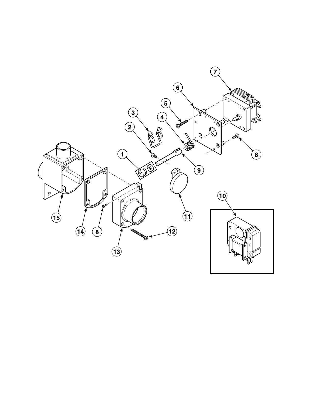
Drain Valve - 2 Inch with Lid
BE100031P_D0073
16
© Copyright, Alliance Laundry Systems LLC – DO NOT COPY or TRANSMIT
D0073
Page 19

Drain Valve - 2 Inch with Lid
REF PART NO. DESCRIPTION COMMENTS
1 G163394 Drain Valve V-Seal
2 209/00025/09 Screw
3 209/00025/03 Drain Valve Spring
4 209/00025/13 Drain Valve Spring
5 209/00025/08 Screw
6 G166553 Drain Valve Motor Plate
7 209/00203/11 Drain Valve Motor 24 Volt
7 209/00052/11 Drain Valve Motor 110 Volt/60 Hertz
7 209/00051/11 Drain Valve Motor 220 Volt/50 or 60 Hertz
8 209/00025/04 Screw
9 209/00025/15 Valve Axle
10 209/00203/21 Coil 24 Volt
10 209/00052/21 Coil 115 Volt/60 Hertz
10 209/00051/21 Coil 220 Volt/50 or 60 Hertz
11 G157107 Sealing Plate Assembly
12 209/00025/06 Screw
13 209/00025/05 Valve Housing
14 209/00025/02 Drain Housing Gasket
15 209/00025/01 Exhaust Valve Housing
D0073
© Copyright, Alliance Laundry Systems LLC – DO NOT COPY or TRANSMIT
17
Page 20
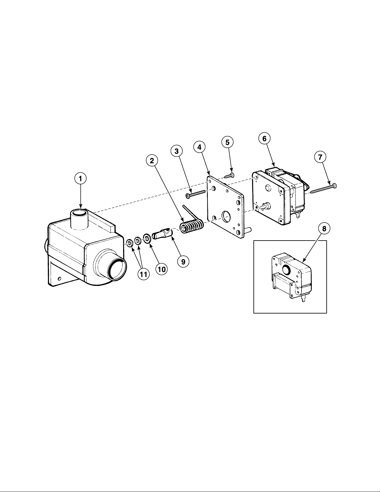
MDP100 Drain Valve - Normally Open
BE100032P_D0073
18
© Copyright, Alliance Laundry Systems LLC – DO NOT COPY or TRANSMIT
D0073
Page 21

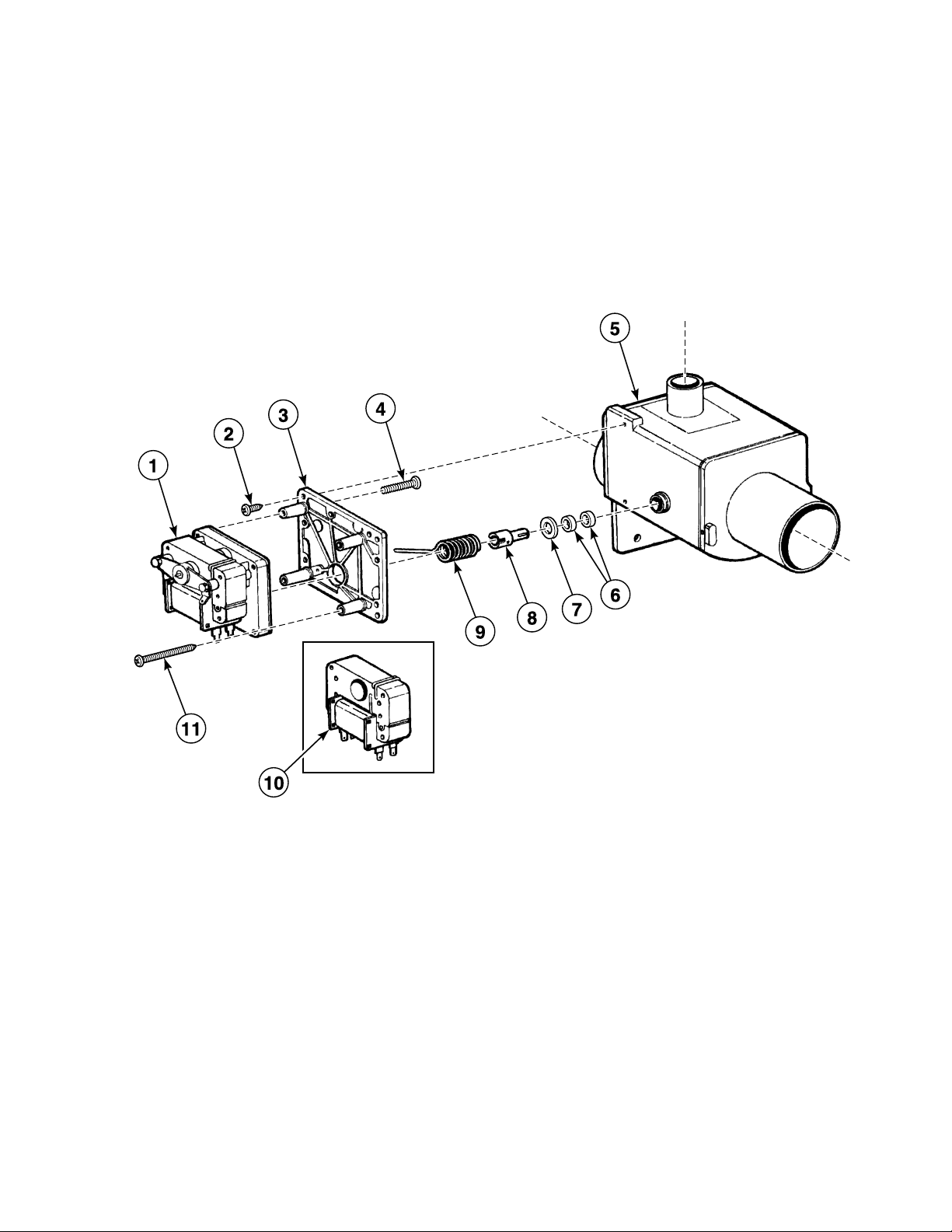
MDP100 Drain Valve - Normally Open
REF PART NO. DESCRIPTION COMMENTS
1 209/00170/01 Exhaust Valve
2 209/00170/02 Drain Valve Spring
3 209/00025/08 Screw
4 209/00170/04 Motor Mounting Plate
5 209/00170/05 Screw
6 209/00203/12 Drain Valve Motor 24 Volt
6 209/00052/12 Drain Valve Motor 110 Volt/60 Hertz
6 209/00170/06 Drain Valve Motor Assembly 220 Volt/50 or 60 Hertz
7 209/00170/07 Screw
8 209/00203/21 Coil 24 Volt
8 209/00052/21 Coil 115 Volt/60 Hertz
8 209/00051/21 Coil 220 Volt/50 or 60 Hertz
9 209/00170/10 Drain Valve Shaft
10 209/00025/12 Washer
11 G163394 Drain Valve V-Seal
D0073
© Copyright, Alliance Laundry Systems LLC – DO NOT COPY or TRANSMIT
19
Page 22
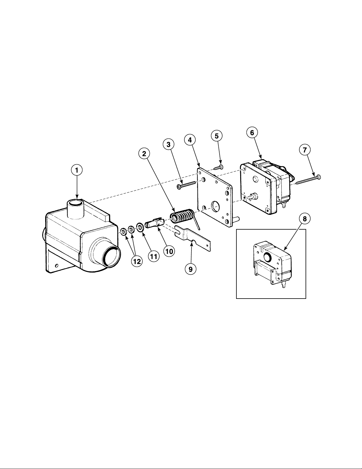
MDP100 Drain Valve - Normally Closed
BE100033P_D0073
20
© Copyright, Alliance Laundry Systems LLC – DO NOT COPY or TRANSMIT
D0073
Page 23

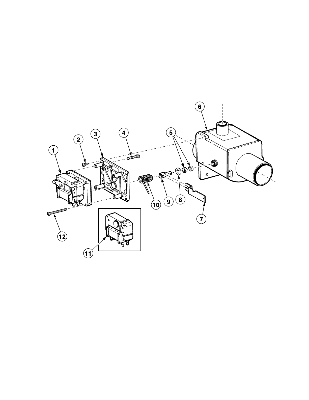
MDP100 Drain Valve - Normally Closed
REF PART NO. DESCRIPTION COMMENTS
1 209/00170/01 Exhaust Valve
2 209/00025/13 Drain Valve Spring
3 209/00025/08 Screw
4 209/00115/04 Drain Valve Motor Mounting Plate
5 209/00170/05 Screw
6 209/00203/11 Drain Valve Motor 24 Volt
6 209/00052/11 Drain Valve Motor 110 Volt/60 Hertz
6 209/00051/11 Drain Valve Motor 220 Volt/50 or 60 Hertz
7 209/00170/07 Screw
8 209/00203/21 Coil 24 Volt
8 209/00052/21 Coil 115 Volt/60 Hertz
8 209/00051/21 Coil 220 Volt/50 or 60 Hertz
9 209/00115/11 Drain Valve Handle
10 209/00170/10 Drain Valve Shaft
11 209/00025/12 Washer
12 G163394 Drain Valve V-Seal
D0073
© Copyright, Alliance Laundry Systems LLC – DO NOT COPY or TRANSMIT
21
Page 24
MDP300 Drain Valve - Normally Open
BE100413P_D0073
22
© Copyright, Alliance Laundry Systems LLC – DO NOT COPY or TRANSMIT
D0073
Page 25

MDP300 Drain Valve - Normally Open
REF PART NO. DESCRIPTION COMMENTS
1 209/00203/11 Drain Valve Motor 24 Volt
1 209/00052/11 Drain Valve Motor 110 Volt/60 Hertz
1 209/00051/11 Drain Valve Motor 220 Volt/50 or 60 Hertz
2 209/00170/05 Screw
3 G166553 Drain Valve Motor Plate
4 209/00025/08 Screw
5 209/00075/05 Drain Valve
6 G163394 Drain Valve V-Seal
7 209/00025/12 Washer
8 209/00170/10 Drain Valve Shaft
9 209/00025/13 Drain Valve Spring
10 209/00203/21 Coil 24 Volt
10 209/00052/21 Coil 115 Volt/60 Hertz
10 209/00051/21 Coil 220 Volt/50 or 60 Hertz
11 209/00170/07 Screw
D0073
© Copyright, Alliance Laundry Systems LLC – DO NOT COPY or TRANSMIT
23
Page 26
MDP300 Drain Valve - Normally Closed
BE100414P_D0073
24
© Copyright, Alliance Laundry Systems LLC – DO NOT COPY or TRANSMIT
D0073
Page 27

MDP300 Drain Valve - Normally Closed
REF PART NO. DESCRIPTION COMMENTS
1 209/00203/12 Drain Valve Motor 24 Volt
1 209/00052/12 Drain Valve Motor 110 Volt/60 Hertz
1 209/00170/06 Drain Valve Motor Assembly 220 Volt/50 or 60 Hertz
2 209/00170/05 Screw
3 209/00115/04 Drain Valve Motor Mounting Plate
4 209/00025/08 Screw
5 G163394 Drain Valve V-Seal
6 209/00075/05 Drain Valve
7 209/00115/11 Drain Valve Handle
8 209/00025/12 Washer
9 209/00170/10 Drain Valve Shaft
10 209/00170/02 Drain Valve Spring
11 209/00212/11 Coil 24 Volt
11 209/00211/11 Coil 115 Volt/60 Hertz
11 209/00051/21 Coil 220 Volt/50 or 60 Hertz
12 209/00170/07 Screw
D0073
© Copyright, Alliance Laundry Systems LLC – DO NOT COPY or TRANSMIT
25
Page 28
MDP90 Drain Valve - Normally Open
BE000030AP_D0073
26
© Copyright, Alliance Laundry Systems LLC – DO NOT COPY or TRANSMIT
D0073
Page 29

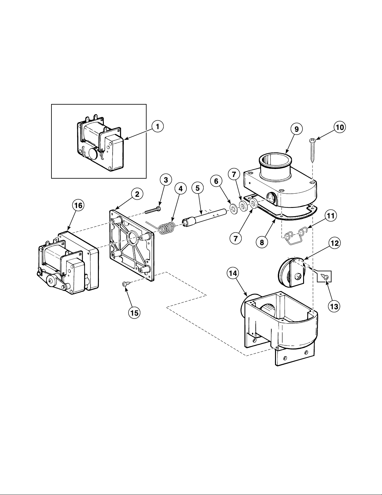
MDP90 Drain Valve - Normally Open
REF PART NO. DESCRIPTION COMMENTS
1 209/00203/21 Coil 24 Volt
1 209/00052/21 Coil 115 Volt/60 Hertz
1 209/00051/21 Coil 220 Volt/50 or 60 Hertz
2 G166553 Drain Valve Motor Plate
3 209/00025/08 Screw
4 209/00025/13 Drain Valve Spring
5 209/00025/15 Valve Axle
6 209/00025/12 Washer
7 G163394 Drain Valve V-Seal
8 209/00025/02 Drain Housing Gasket
9 209/00256/05 Valve
10 209/00025/06 Screw
11 209/00025/03 Drain Valve Spring
12 G157107 Sealing Plate Assembly
13 209/00025/09 Screw
14 209/00256/00 Drain Valve
15 209/00170/05 Screw
16 209/00203/11 Drain Valve Motor 24 Volt
16 209/00052/11 Drain Valve Motor 110 Volt/60 Hertz
16 209/00051/11 Drain Valve Motor 220 Volt/50 or 60 Hertz
D0073
© Copyright, Alliance Laundry Systems LLC – DO NOT COPY or TRANSMIT
27
Page 30
MDP90 Drain Valve - Normally Closed
BE000031AP_D0073
28
© Copyright, Alliance Laundry Systems LLC – DO NOT COPY or TRANSMIT
D0073
Page 31

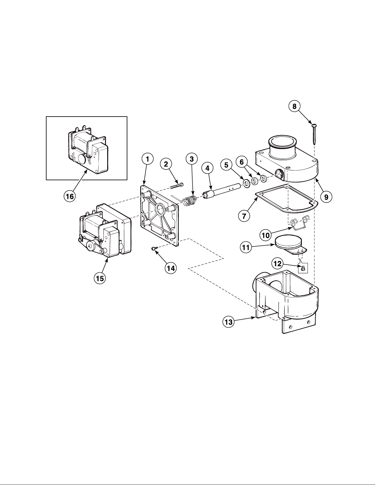
MDP90 Drain Valve - Normally Closed
REF PART NO. DESCRIPTION COMMENTS
1 G166553 Drain Valve Motor Plate
2 209/00025/08 Screw
3 209/00170/02 Drain Valve Spring
4 209/00025/15 Valve Axle
5 209/00025/12 Washer
6 G163394 Drain Valve V-Seal
7 209/00025/02 Drain Housing Gasket
8 209/00025/06 Screw
9 209/00256/05 Valve
10 209/00025/03 Drain Valve Spring
11 G157107 Sealing Plate Assembly
12 209/00025/09 Screw
13 209/00256/00 Drain Valve
14 209/00170/05 Screw
15 209/00203/12 Drain Valve Motor 24 Volt
15 209/00052/12 Drain Valve Motor 110 Volt/60 Hertz
15 209/00170/06 Drain Valve Motor Assembly 220 Volt/50 or 60 Hertz
16 209/00203/21 Coil 24 Volt
16 209/00052/21 Coil 115 Volt/60 Hertz
16 209/00051/21 Coil 220 Volt/50 or 60 Hertz
D0073
© Copyright, Alliance Laundry Systems LLC – DO NOT COPY or TRANSMIT
29
Page 32

Upper Back Panel
BE100071P_D0073
A. B.
B.
A.
30
© Copyright, Alliance Laundry Systems LLC – DO NOT COPY or TRANSMIT
D0073
Page 33

Upper Back Panel
REF PART NO. DESCRIPTION COMMENTS
1 207/00006/00 Screw
2 202/00004/00 Washer
3 209/00057/00 Terminal
4 207/00003/00 Screw
5 209/00005/00 Terminal Block
6 204/00007/00 Nut
7 208/00001/00 Screw
8 201/00007/00 Washer
9 208/00002/00 Nut
10 111/00086/00 Rear Panel PB3 supply dispenser
10 111/01164/10 Backbridge PB2 and PB3 supply dispensers
10 111/00040/00 Rear Panel PB2 supply dispenser
10 111/00040/AO Rear Panel PB2 supply dispenser with overflow
11 223/00018/00 Hose
12 223/00011/00 Hose Clamp
13 209/00202/00 Fuse Holder
14 209/00468/00 Fuse
15 211/00097/00 Cordlock
16 211/00022/00 Nut
17 209/00006/00 Terminal
18 203/00006/00 Washer
19 208/00007/00 Screw
20 111/00200/00 Cover Plate
21 229/00001/00 Sticker
22 211/00084/00 Plug 20.5 mm diameter
22 211/00085/00 Stopper 25.5 mm diameter
23 203/00007/00 Washer
24 211/00086/00 Stopper 28 mm diameter
24 211/00087/00 Plug 30 mm diameter
25 204/00008/00 Nut
D0073
© Copyright, Alliance Laundry Systems LLC – DO NOT COPY or TRANSMIT
31
Page 34

Water Inlet Valves
BE100035P_D0073
32
© Copyright, Alliance Laundry Systems LLC – DO NOT COPY or TRANSMIT
D0073
Page 35

Water Inlet Valves
REF PART NO. DESCRIPTION COMMENTS
1 F200165 Water Hose
2 223/00060/00 Filter Mueller
2 209/00001/10 Filter Elbi
2 223/00051/08 Filter Techno
3 209/00276/00 Inlet Valve
4 207/00004/00 Screw
5 209/00110/00 2-Way Inlet Valve
6 209/00110/00 2-Way Inlet Valve BSP
6 209/00370/00 2-Way Inlet Valve USA
7 223/00010/00 Hose Clamp
8 223/00044/00 Water Hose
9 209/00277/00 3-Way Inlet Valve
10 223/00073/00 Connector
11 223/00041/00 Water Inlet Tee
12 223/00049/01 Joint
D0073
© Copyright, Alliance Laundry Systems LLC – DO NOT COPY or TRANSMIT
33
Page 36

Water Inlet Valves - Invesys
BE100036P_D0073
34
© Copyright, Alliance Laundry Systems LLC – DO NOT COPY or TRANSMIT
D0073
Page 37

Water Inlet Valves - Invesys
REF PART NO. DESCRIPTION COMMENTS
1 209/00001/01 Coil
2 209/00001/02 Screw
3 209/00001/03 2-Way Plate
4 209/00001/04 Core Holder
5 209/00001/11 1-Way Plate
6 209/00001/05 Spring
7 209/00001/06 Core
8 209/00001/07 Diaphragm
9 209/00001/08 3-Way Inlet Valve Elbi
9 209/00112/12 3-Way Valve Mueller
10 223/00051/01 Screw
11 223/00051/02 2-Way Inlet Valve
12 223/00051/03 Core Holder
13 223/00051/04 Spring
14 223/00051/05 Core
15 223/00051/06 Diaphragm
16 209/00114/08 2-Way Valve Elbi
17 209/00090/12 2-Way Valve
18 209/00090/08 Diaphragm
19 209/00090/15 Spring
20 209/00090/07 Core
21 209/00090/06 Spring
22 209/00090/05 Core Holder
23 209/00045/07 Assembly Plate
24 209/00090/03 Screw
25 209/00090/02 Spring
26 209/00178/01 Inlet Valve Solenoid 115 Volt
26 209/00090/01 Inlet Valve Solenoid 220 Volt
D0073
© Copyright, Alliance Laundry Systems LLC – DO NOT COPY or TRANSMIT
35
Page 38

Water Inlet Valves - Elbi and Techno
BE100008P_D0073
ELBI
TECHNO
ELBI
36
© Copyright, Alliance Laundry Systems LLC – DO NOT COPY or TRANSMIT
D0073
Page 39

Water Inlet Valves - Elbi and Techno
REF PART NO. DESCRIPTION COMMENTS
1 209/00001/01 Coil
2 209/00001/02 Screw
3 209/00001/03 2-Way Plate
4 209/00001/04 Core Holder
5 209/00001/11 1-Way Plate
6 209/00001/05 Spring
7 209/00001/06 Core
8 209/00001/07 Diaphragm
9 209/00001/08 3-Way Inlet Valve
10 223/00051/01 Screw
11 223/00051/02 2-Way Inlet Valve
12 223/00051/03 Core Holder
13 223/00051/04 Spring
14 223/00051/05 Core
15 223/00051/06 Diaphragm
16 223/00051/07 2-Way Inlet Valve
17 209/00048/08 1-Way Inlet Valve
18 209/00048/03 1-Outlet Plate
D0073
© Copyright, Alliance Laundry Systems LLC – DO NOT COPY or TRANSMIT
37
Page 40

Water Inlet Valves - Techno
BE100009P_D0073
38
© Copyright, Alliance Laundry Systems LLC – DO NOT COPY or TRANSMIT
D0073
Page 41

Water Inlet Valves - Techno
REF PART NO. DESCRIPTION COMMENTS
1 223/00051/01 Screw
2 223/00051/11 Coil
3 223/00051/03 Core Holder
4 223/00051/04 Spring
5 223/00051/05 Core
6 223/00051/06 Diaphragm
7 223/00051/09 Plate
8 223/00051/12 1-Way Inlet Valve
9 223/00051/13 3-Way Inlet Valve
10 223/00051/02 2-Way Inlet Valve
D0073
© Copyright, Alliance Laundry Systems LLC – DO NOT COPY or TRANSMIT
39
Page 42

PB2 Supply Dispenser - Models Through 12/31/1991
BE100072P_D0073
40
© Copyright, Alliance Laundry Systems LLC – DO NOT COPY or TRANSMIT
D0073
Page 43

PB2 Supply Dispenser - Models Through 12/31/1991
REF PART NO. DESCRIPTION COMMENTS
1 223/00044/00 Water Hose
2 223/00010/00 Hose Clamp
3 204/00201/00 Nut
4 201/00002/00 Washer
5 223/00001/07 Washer
6 223/00001/05 Injector
7 223/00001/06 Mounting Plate
8 208/00130/00 Screw
9 223/00003/00 Lid Seal
10 223/00001/03 Separator Plate
11 223/00001/01 Soap Dispenser
12 223/00013/00 Hose Clamp
13 223/00007/00 Hose
14 223/00001/04 Prewash and Mainwash Nozzle
D0073
© Copyright, Alliance Laundry Systems LLC – DO NOT COPY or TRANSMIT
41
Page 44

PB3 Supply Dispenser - Models Starting 1/1/1992
CFD480P_D0073
42
© Copyright, Alliance Laundry Systems LLC – DO NOT COPY or TRANSMIT
D0073
Page 45

PB3 Supply Dispenser - Models Starting 1/1/1992
REF PART NO. DESCRIPTION COMMENTS
1 223/00102/07 Hose Vent
2 223/00013/00 Hose Clamp
3 223/00107/02 Vent Hose *30, *110 and *132 models
3 223/00107/00 Soap Dispenser Air Breather Hose *35 and *165 models
4 223/00109/00 Soap Dispenser Gasket
5 223/00102/06 Soap Spray Nozzle
6 223/00102/05 Softener Spray Nozzle
7 123/00107/00 Anti-Splash Plate Sigma models
7 123/00103/06 Soap Box Assembly Plate All other models
8 223/00102/03 Rinse Insert
9 223/00102/04 Soap Dispenser Rinse Siphon
10 208/00130/00 Screw
11 223/00102/30 Soap Dispenser Assembly
12 223/00023/00 Hose Clamp
13 223/00115/00 Hose
14 223/00010/00 Hose Clamp
15 223/00044/00 Water Hose
16 204/00105/00 Nut
17 203/00008/00 Washer
18 207/00106/00 Screw
D0073
© Copyright, Alliance Laundry Systems LLC – DO NOT COPY or TRANSMIT
43
Page 46

Control Panel - Ram Stetter
BE100039P_D0073
44
© Copyright, Alliance Laundry Systems LLC – DO NOT COPY or TRANSMIT
D0073
Page 47

Control Panel - Ram Stetter
REF PART NO. DESCRIPTION COMMENTS
1 209/00151/00 Lamp
2 111/00044/00 Front Panel
3 111/10140/00 Assembly Plate
4 211/00115/00 Thermostat
5 201/00008/00 Washer
6 203/00006/00 Washer
7 204/00007/00 Nut
8 209/00082/00 Program Card
9 223/00065/01 Washer
10 223/00065/00 Thermostat Seal
11 209/00081/00 Timer
12 207/00011/00 Screw
13 224/00036/00 Fastener
14 206/00027/00 Bolt
15 202/00004/00 Washer
16 111/00079/00 Assembly Plate
17 203/00007/00 Washer
18 204/00008/00 Nut
19 202/00003/00 Washer
D0073
© Copyright, Alliance Laundry Systems LLC – DO NOT COPY or TRANSMIT
45
Page 48

Control Panel - Fiber
BE100041P_D0073
46
© Copyright, Alliance Laundry Systems LLC – DO NOT COPY or TRANSMIT
D0073
Page 49

Control Panel - Fiber
REF PART NO. DESCRIPTION COMMENTS
1 111/10176/00 Front Panel
2 225/00277/AOL Front Panel
3 209/00254/21 Pushbutton
4 209/00249/00 Pilot Light
5 209/00254/00 Pushbutton
6 209/00152/00 Lens Cover
7 209/00257/00 Card Reader
8 201/00008/00 Washer
9 204/00007/00 Nut
D0073
© Copyright, Alliance Laundry Systems LLC – DO NOT COPY or TRANSMIT
47
Page 50

Control Panel - 10 Button
BE100074P_D0073
48
© Copyright, Alliance Laundry Systems LLC – DO NOT COPY or TRANSMIT
D0073
Page 51

Control Panel - 10 Button
REF PART NO. DESCRIPTION COMMENTS
1 111/00091/00 Front Bridge
1 111/00043/00 Front Panel Coin models
1 111/00084/00 Front Panel OPL models
2 209/00175/00 Selector Switch 1 through 5
3 209/00176/00 Selector Switch 6 through 10
4 206/00016/00 Bolt
5 203/00005/00 Washer
6 204/00013/00 Nut
7 209/00143/00 Thermostat 3 temperature
7 209/00144/00 Thermostat 2 temperature
8 223/00065/02 Thermostat Joint
9 223/00065/00 Thermostat Seal
10 223/00065/01 Washer
D0073
© Copyright, Alliance Laundry Systems LLC – DO NOT COPY or TRANSMIT
49
Page 52

Control Panel - PLC9 OPL
BE100045P_D0073
A
B C D E F
G
H
A
B
C
D
E
F
G
H
50
© Copyright, Alliance Laundry Systems LLC – DO NOT COPY or TRANSMIT
D0073
Page 53

Control Panel - PLC9 OPL
REF PART NO. DESCRIPTION COMMENTS
1 201/00008/00 Washer
2 204/00007/00 Nut
3 209/00151/00 Lamp
4 111/10174/00 Front Panel
5 225/00266/AOL Front Panel
6 209/00099/05 Contact
7 209/00099/04 Button
8 209/00252/00 Button
9 209/00099/06 Contact Switch
10 209/00099/08 Button
11 209/00253/00 Emergency Stop Button Kit
12 209/00099/07 Contact Switch
13 209/00251/00 Button
14 209/00280/01 Button
15 209/00249/00 Pilot Light
16 209/00254/00 Pushbutton
17 209/00266/00 Timer
18 207/00008/00 Screw
19 203/00006/00 Washer
20 204/00114/00 Nut
21 111/32106/00 Plate
22 207/00025/00 Screw
23 209/00152/00 Lens Cover
24 203/00007/00 Washer
25 204/00008/00 Nut
26 211/00106/00 Spacer
27 223/00123/00 Washer
D0073
© Copyright, Alliance Laundry Systems LLC – DO NOT COPY or TRANSMIT
51
Page 54

Control Panel - PLC9 Coin
BE100046P_D0073
52
© Copyright, Alliance Laundry Systems LLC – DO NOT COPY or TRANSMIT
D0073
Page 55

Control Panel - PLC9 Coin
REF PART NO. DESCRIPTION COMMENTS
1 209/00217/00 Coin Display
2 209/00266/00 Timer
3 204/00008/00 Nut
4 203/00007/00 Washer
5 223/00123/00 Washer
6 211/00106/00 Spacer
7 207/00025/00 Screw
8 204/00007/00 Nut
9 203/00006/00 Washer
10 111/10174/00 Front Panel
11 111/00062/00 Assembly Plate
12 223/10066/00 Display
13 209/00154/00 Lens Cover Orange
13 209/00152/00 Lens Cover Red
14 209/00280/01 Button
15 209/00249/00 Pilot Light
16 209/00099/07 Contact Switch
16 209/00254/00 Pushbutton
17 209/00151/00 Lamp
18 207/00008/00 Screw
D0073
© Copyright, Alliance Laundry Systems LLC – DO NOT COPY or TRANSMIT
53
Page 56

Control Panel - PC20 and PC30
BE100048P_D0073
54
© Copyright, Alliance Laundry Systems LLC – DO NOT COPY or TRANSMIT
D0073
Page 57

Control Panel - PC20 and PC30
REF PART NO. DESCRIPTION COMMENTS
1 204/00007/00 Nut
2 203/00006/00 Washer
3 209/00326/00 Programming Switch
4 209/00099/05 Contact
5 229/00244/00 Keypad
6 201/00008/00 Washer
7 202/00004/00 Washer
8 204/00116/00 Nut
9 209/00290/02 Keyboard
D0073
© Copyright, Alliance Laundry Systems LLC – DO NOT COPY or TRANSMIT
55
Page 58

Control Panel - Micro-20
BE000035AP_D0073
56
© Copyright, Alliance Laundry Systems LLC – DO NOT COPY or TRANSMIT
D0073
Page 59

Control Panel - Micro-20
REF PART NO. DESCRIPTION COMMENTS
1 229/00262/00 Circuit Board Cover
2 209/00440/00 Printboard Models through 8/31/01
2 209/00440/70 Printboard Models starting 9/1/01
3 204/00116/00 Nut
4 211/00122/00 Standoff
5 204/00009/00 Nut
6 201/00008/00 Washer
7 229/00255/00 Insulating Sticker
8 111/00181/00 Upper Front Panel Stainless steel
8 111/00181/10 Upper Front Panel Epoxy
9 225/00291/AOL Front Panel Coin models
9 225/00292/AOL Front Panel OPL models
10 225/00308/00 Sticker Coin models
10 225/00309/00 Sticker OPL models
11 225/00316/00 Plexi Frame
12 209/00248/00 Mushroom Pushbutton
13 209/00520/00 Telem Sticker
14 209/00099/05 Contact
15 209/00099/06 Contact Switch
16 209/00266/01 Eprom
17 209/00439/00 Fuse
D0073
© Copyright, Alliance Laundry Systems LLC – DO NOT COPY or TRANSMIT
57
Page 60

Control Panel Decals - 10 Button
BE100083P_D0073
58
© Copyright, Alliance Laundry Systems LLC – DO NOT COPY or TRANSMIT
D0073
Page 61

Control Panel Decals - 10 Button
REF PART NO. DESCRIPTION COMMENTS
1 225/00287/ABL Front Panel Coin models
2 225/00153/ABL Front Panel OPL models
D0073
© Copyright, Alliance Laundry Systems LLC – DO NOT COPY or TRANSMIT
59
Page 62

Electrical Component Mounting Plate -
BE100038P_D0073
Boiler Fed or Steam Heat Models
60
© Copyright, Alliance Laundry Systems LLC – DO NOT COPY or TRANSMIT
D0073
Page 63

Electrical Component Mounting Plate -
Boiler Fed or Steam Heat Models
REF PART NO. DESCRIPTION COMMENTS
1 206/00021/00 Screw
2 111/00035/00 Mounting Plate
3 204/00007/00 Nut
4 207/00008/00 Screw
5 209/00005/00 Terminal Block
6 209/00040/00 Timer 110 Volt/60 Hertz
6 209/00012/00 Reversing Timer 220 Volt/50 Hertz
6 209/00013/00 Reversing Timer 220 Volt/60 Hertz
7 111/00124/00 Mounting Plate *30, *110 and *132 models
7 111/00039/AO Mounting Plate *35 and *165 models
8 203/00008/00 Washer
9 207/00004/00 Screw
D0073
© Copyright, Alliance Laundry Systems LLC – DO NOT COPY or TRANSMIT
61
Page 64

Electrical Component Mounting Plate - Ram Stetter Control
BE100040P_D0073
62
© Copyright, Alliance Laundry Systems LLC – DO NOT COPY or TRANSMIT
D0073
Page 65

Electrical Component Mounting Plate - Ram Stetter Control
REF PART NO. DESCRIPTION COMMENTS
1 111/00424/00 Pressure Switch Bracket
2 208/00007/00 Screw
3 209/00007/30 Pressure Switch
4 209/06150/02 Contactor LC1D5011M5
4 209/00177/02 Contactor LC1D2510M5
4 209/00148/02 Contactor LC1D1810M5
4 209/00041/04 Contactor LC1D0901M5
4 209/00149/02 Contactor LC1D3210M5
4 209/00056/02 Contactor LC1D4011M5
5 209/00041/03 Contactor
6 206/00021/00 Screw
7 111/00035/00 Mounting Plate
8 209/00012/00 Reversing Timer 220 Volt/50 Hertz
8 209/00013/00 Reversing Timer 220 Volt/60 Hertz
9 207/00004/00 Screw
10 203/00006/00 Washer
11 204/00007/00 Nut
12 210/10007/00 Connection
13 206/00015/00 Bolt
14 111/00145/00 Assembly Plate
15 204/00005/00 Nut
16 202/00003/00 Washer
17 203/00004/00 Washer
18 111/00037/AO Assembly Plate *30, *110 and *132 models
18 111/00038/AO Assembly Plate *35 and *165 models
19 223/00011/00 Hose Clamp
20 223/00120/00 Pressure Hose Kit
21 209/00243/00 Thermostat
22 207/00008/00 Screw
D0073
© Copyright, Alliance Laundry Systems LLC – DO NOT COPY or TRANSMIT
63
Page 66

Electrical Component Mounting Plate - Fiber Control
BE100073P_D0073
64
© Copyright, Alliance Laundry Systems LLC – DO NOT COPY or TRANSMIT
D0073
Page 67

Electrical Component Mounting Plate - Fiber Control
REF PART NO. DESCRIPTION COMMENTS
1 209/00041/04 Contactor LC1D0901M5
1 209/00148/02 Contactor LC1D1810M5
1 209/00149/02 Contactor LC1D3210M5
1 209/06150/02 Contactor LC1D5011M5
1 209/00177/02 Contactor LC1D2510M5
1 209/00056/02 Contactor LC1D4011M5
2 209/00007/10 Water Level Switch
3 209/00012/00 Reversing Timer IO858; 220 Volt/60 Hertz
3 209/00013/00 Reversing Timer IO861; 220 Volt/60 Hertz
3 209/00040/00 Timer IO970; 110 Volt/60 Hertz
4 209/00109/00 Timer IO829; 220 Volt/60 Hertz; Green
4 209/00108/00 Timer IO609; 220 Volt/50 Hertz; Green
4 209/00107/00 Timer IO1134; 220 Volt/60 Hertz
4 209/00165/00 Timer IO1650; 110 Volt/60 Hertz
5 225/00001/00 Program Indicator
6 209/00007/01 Clip
7 223/00017/00 Pressure Hose
8 209/00124/00 Contactor
9 209/00054/00 Thermostat
9 209/00243/00 Thermostat
10 211/00083/00 Wire Holder
11 209/00041/04 Contactor LC1D0901M5
11 209/00042/02 Contactor LC1D09019F7
12 209/00101/02 Switch LADT49
12 209/00103/02 Switch LA3-DR49
13 206/00021/00 Screw
14 209/00041/03 Contactor LC1D09019M7
14 209/00042/02 Contactor LC1D09019F7
15 206/00014/00 Bolt
16 203/00004/00 Washer
17 111/00016/00 Mounting Plate
18 201/00007/00 Washer
19 204/00005/00 Nut
20 206/00015/00 Bolt
21 111/00037/AO Assembly Plate *30, *110 and *132 models
21 111/00038/AO Assembly Plate *35 and *165 models
22 223/00011/00 Hose Clamp
23 223/00015/00 Level Switch Elbow
24 223/00016/00 Hose Barb
25 223/00038/00 Seal Assembly
26 223/00048/00 Ring
27 204/00007/00 Nut
28 202/00004/00 Washer
29 203/00006/00 Washer
30 207/00003/00 Screw
D0073
© Copyright, Alliance Laundry Systems LLC – DO NOT COPY or TRANSMIT
65
Page 68

Electrical Component Mounting Plate - 10 Button Control
BE100044P_D0073
66
© Copyright, Alliance Laundry Systems LLC – DO NOT COPY or TRANSMIT
D0073
Page 69

Electrical Component Mounting Plate - 10 Button Control
REF PART NO. DESCRIPTION COMMENTS
1 111/00424/00 Pressure Switch Bracket
2 208/00007/00 Screw
3 209/00007/30 Pressure Switch
4 209/00177/02 Contactor LC1D2510M5
4 209/00041/04 Contactor LC1D0901M5
4 209/00056/02 Contactor LC1D4011M5
4 209/06150/02 Contactor LC1D5011M5
4 209/00149/02 Contactor LC1D3210M5
4 209/00148/02 Contactor LC1D1810M5
5 209/00041/03 Contactor
6 209/00279/00 Lock
7 209/00299/00 Protector LR2-D13169/9-13A
7 209/00132/00 Protector LR1-D09321/13-18A
7 209/00285/00 Protector LR2-D1312/5,5-8A
7 209/00283/00 Protector LR2-D1306/1-1,6A
7 209/00264/00 Protector LR2-D1310/4-6A
7 209/00263/00 Protector LR2-D1308/2,5-4A
7 209/00284/00 Protector LR2-D1307/1,6-2,5A
7 209/00265/00 Protector LR2-D1314/7-10A
8 209/00005/00 Terminal Block
9 207/00003/00 Screw
10 203/00006/00 Washer
11 204/00007/00 Nut
12 204/00005/00 Nut
13 202/00003/00 Washer
14 203/00004/00 Washer
15 206/00015/00 Bolt
16 111/00124/00 Mounting Plate *30, *110 and *132 models
16 111/00039/AO Mounting Plate *35 and *165 models
17 223/00011/00 Hose Clamp
18 223/00120/00 Pressure Hose Kit
19 206/00021/00 Screw
20 209/00243/00 Thermostat
21 207/00008/00 Screw
D0073
© Copyright, Alliance Laundry Systems LLC – DO NOT COPY or TRANSMIT
67
Page 70

Electrical Component Mounting Plate - PC30 Control
BE100075P_D0073
68
© Copyright, Alliance Laundry Systems LLC – DO NOT COPY or TRANSMIT
D0073
Page 71

Electrical Component Mounting Plate - PC30 Control
REF PART NO. DESCRIPTION COMMENTS
1 209/00279/00 Lock
2 246/00092/00 Gasket
3 111/00105/00 Cover Plate
3 111/00142/00 Cover Plate
4 207/00004/00 Screw
5 203/00006/00 Washer
6 204/00007/00 Nut
7 204/00008/00 Nut
8 223/00123/00 Washer
9 111/00138/00 Axle
10 203/00007/00 Washer
11 207/00118/00 Screw
12 209/00290/01 Printboard Uses 209/00505/04P Battery
13 225/00019/00 Holder
14 207/00003/00 Screw
15 209/00005/00 Terminal Block
16 111/00139/00 Assembly Plate Models WE110_PC30 and WE132_PC30
16 111/00143/00 Assembly Plate Model WE165_PC30
17 225/00027/00 Cable Duct
18 209/00290/06 Detector
19 210/10007/00 Connection
20 209/00141/00 Plug
21 111/00137/00 Assembly Plate
22 209/00263/00 Protector LR2-D1308/2,5-4A
22 209/00264/00 Protector LR2-D1310/4-6A
22 209/00265/00 Protector LR2-D1314/7-10A
22 209/00284/00 Protector LR2-D1307/1,6-2,5A
22 209/00285/00 Protector LR2-D1312/5,5-8A
22 209/00132/00 Protector LR1-D09321/13-18A
22 209/00299/00 Protector LR2-D13169/9-13A
22 209/00283/00 Protector LR2-D1306/1-1,6A
23 209/00041/03 Contactor
24 209/00148/02 Contactor LC1D1810M5
24 209/06150/02 Contactor LC1D5011M5
24 209/00056/02 Contactor LC1D4011M5
24 209/00149/02 Contactor LC1D3210M5
24 209/00177/02 Contactor LC1D2510M5
24 209/00041/04 Contactor LC1D0901M5
D0073
© Copyright, Alliance Laundry Systems LLC – DO NOT COPY or TRANSMIT
69
Page 72

Door Lock (Drawing 1 of 4)
BE100049P_D0073
70
© Copyright, Alliance Laundry Systems LLC – DO NOT COPY or TRANSMIT
D0073
Page 73

Door Lock (Drawing 1 of 4)
REF PART NO. DESCRIPTION COMMENTS
1 204/00005/00 Nut
2 203/00004/00 Washer
3 206/00012/00 Bolt
4 208/00008/00 Clamp
5 124/00004/00 Connection Rod
6 209/00028/00 Door Solenoid 110 Volt/60 Hertz
6 209/00017/00 Door Interlock Coil 220 Volt/50 Hertz
6 209/00018/00 Door Interlock Coil 220 Volt/60 Hertz
7 206/00021/00 Screw
8 224/00006/00 Solenoid
9 203/00006/00 Washer
10 207/00004/00 Screw
11 208/00003/00 Cotter Pin
12 124/00005/00 Wire Bridge
13 224/00007/00 Spring
14 224/00008/00 Spring
15 124/00002/00 Bridge
16 204/00009/00 Nut
D0073
© Copyright, Alliance Laundry Systems LLC – DO NOT COPY or TRANSMIT
71
Page 74

Door Lock (Drawing 2 of 4)
BE100050P_D0073
72
© Copyright, Alliance Laundry Systems LLC – DO NOT COPY or TRANSMIT
D0073
Page 75

Door Lock (Drawing 2 of 4)
REF PART NO. DESCRIPTION COMMENTS
1 204/00005/00 Nut
2 203/00004/00 Washer
3 206/00012/00 Bolt
4 208/00008/00 Clamp
5 207/00003/00 Screw
6 202/00004/00 Washer
7 124/00029/00 Unlatching Wire
8 208/00003/00 Cotter Pin
9 207/00004/00 Screw
10 203/00006/00 Washer
11 309/00028/00 Door Solenoid 110 Volt/60 Hertz
11 209/00017/00 Door Interlock Coil 220 Volt/50 Hertz
11 209/00018/00 Door Interlock Coil 220 Volt/60 Hertz
12 224/00006/00 Solenoid
13 206/00021/00 Screw
14 204/00007/00 Nut
15 224/00021/00 Lock Spring
16 206/00011/00 Bolt
17 202/00003/00 Washer
18 124/00020/00 Lock
19 204/00009/00 Nut
20 124/00004/00 Connection Rod
21 207/00006/00 Screw
22 203/00007/00 Washer
23 204/00008/00 Nut
24 209/00145/00 Microswitch
25 206/00015/00 Bolt
26 124/00023/00 Assembly Plate
27 124/00005/00 Wire Bridge
28 224/00007/00 Spring
29 224/00008/00 Spring
30 124/00019/00 Panel
D0073
© Copyright, Alliance Laundry Systems LLC – DO NOT COPY or TRANSMIT
73
Page 76

Door Lock (Drawing 3 of 4)
BE100051P_D0073
74
© Copyright, Alliance Laundry Systems LLC – DO NOT COPY or TRANSMIT
D0073
Page 77

Door Lock (Drawing 3 of 4)
REF PART NO. DESCRIPTION COMMENTS
1 208/00008/00 Clamp
2 217/00020/00 Spring
3 206/00012/00 Bolt
4 224/00009/00 Door Lock Spring
5 204/00005/00 Nut
6 203/00004/00 Washer
7 124/00005/00 Wire Bridge
8 224/00015/00 Door Latch Cord
9 124/00010/00 Door Lock
10 206/00018/00 Screw
11 225/00001/00 Program Indicator
12 204/00009/00 Nut
13 124/00013/00 Bridge
D0073
© Copyright, Alliance Laundry Systems LLC – DO NOT COPY or TRANSMIT
75
Page 78

Door Lock (Drawing 4 of 4)
BE100076P_D0073
76
© Copyright, Alliance Laundry Systems LLC – DO NOT COPY or TRANSMIT
D0073
Page 79

Door Lock (Drawing 4 of 4)
REF PART NO. DESCRIPTION COMMENTS
1 207/00135/00 Screw
2 217/00052/03 Door Lock Spacer
3 B12517701 Door Lock Assembly
4 204/00008/00 Nut
5 203/00007/00 Washer
6 211/00106/00 Spacer
7 207/00006/00 Screw
8 209/00275/04 Door Lock Board
9 217/00021/00 O-Ring
10 207/00112/00 Screw
11 B12517701 Door Lock Assembly
12 211/00109/00 Door Lock Pin Kit
13 209/00271/00 Microswitch
14 209/00272/00 Door Lock Microswitch
15 204/00103/00 Nut
16 207/00102/00 Screw
17 217/00052/02 Door Lock Pin Kit
18 217/00017/03 Lock Shaft
19 201/00018/00 Washer
20 207/00109/00 Screw
21 B12625101 Microswitch
22 209/00274/00 Door Lock Solenoid
23 211/00110/00 Lock
24 224/00040/00 Lever Spring
25 224/00043/00 Interlock Coil Spring
26 224/00015/00 Door Latch Cord
27 217/00052/04 Interlock Lever
28 201/00017/00 Washer
D0073
© Copyright, Alliance Laundry Systems LLC – DO NOT COPY or TRANSMIT
77
Page 80

Door Handle
BE100018P_D0073
78
© Copyright, Alliance Laundry Systems LLC – DO NOT COPY or TRANSMIT
D0073
Page 81

Door Handle
REF PART NO. DESCRIPTION COMMENTS
1 217/00013/02 Door Handle
2 217/00013/03 Door Lock Spring
3 217/00051/00 Door Handle
4 217/00013/09 Door Mounting Pin
5 217/00013/11 Door Circlip
6 217/00013/12 Door Handle
7 217/00013/13 Door Handle Hook
8 217/00013/15 Door Handle Locking Pin
9 217/00013/14 Door Handle Spring
10 217/00013/16 Door Handle Assembly Plate
11 217/00013/08 Door Locking Pin
12 217/00013/07 Door Locking Grip
13 217/00013/06 Door Roller
14 217/00013/05 Door Axle Roller
15 217/00013/04 Door Handle Latch
D0073
© Copyright, Alliance Laundry Systems LLC – DO NOT COPY or TRANSMIT
79
Page 82

Door
BE100077P_D0073
80
© Copyright, Alliance Laundry Systems LLC – DO NOT COPY or TRANSMIT
D0073
Page 83

Door
REF PART NO. DESCRIPTION COMMENTS
1 219/00006/00 Tub Front Gasket
2 135/00033/00 Tub Front
3 124/00001/00 Protection Plate
4 204/00005/00 Nut
5 217/00021/00 O-Ring
6 217/00017/02 Protection Block
7 207/00102/00 Screw
8 217/00009/02 Door Hinge Assembly
9 217/00009/01 Door Hinge
10 117/00010/00 Door Hinge Spacer 1 mm
10 117/00011/00 Door Hinge Spacer 2 mm
11 118/00064/00 Door Octagonal
11 118/00046/10 Door Frame Round
12 207/00116/00 Screw
13 217/00051/00 Door Handle
14 217/00016/00 Door Handle Stop
15 204/00103/00 Nut
16 217/00020/00 Spring
17 211/00105/00 Pin
18 217/00019/00 Holder
19 B12500801 Screw
20 217/00015/00 Door Glass Seal
21 B12449701 Door Glass
22 202/00003/00 Washer
23 204/00106/00 Nut
24 207/00112/00 Screw
25 217/00017/00 Door Lock Assembly
26 217/00038/00 Insulation Plate
27 209/00023/00 Door Switch
28 207/00109/00 Screw
29 224/00003/00 Interlock Pin
30 208/00004/00 Pin
31 124/00005/00 Wire Bridge
32 202/00101/00 Washer
33 205/00104/00 Bolt
D0073
© Copyright, Alliance Laundry Systems LLC – DO NOT COPY or TRANSMIT
81
Page 84

Shell and Basket
BE100078P_D0073
82
© Copyright, Alliance Laundry Systems LLC – DO NOT COPY or TRANSMIT
D0073
Page 85

Shell and Basket
REF PART NO. DESCRIPTION COMMENTS
1 204/00002/00 Nut
2 203/00001/00 Washer
3 206/00001/00 Screw
4 119/00038/00 Tub Ring
5 204/00004/00 Bolt
6 203/00003/00 Washer
7 202/00002/00 Washer
8 204/00005/00 Nut
9 201/00007/00 Washer
10 206/00007/00 Screw
11 113/00025/00 Steam Injector Plate Assembly
12 119/00039/00 Steam Injector *110 models
12 119/00082/00 Steam Injector *30, *35, *132 and *165 models
13 203/00004/00 Washer
14 206/00013/00 Bolt
15 209/00116/00 Heating Element 1400W; 220 Volt
15 209/00563/30 Heating Element 2000W; 220/240 Volt
15 209/00049/00 Heating Element 3000W; 220/240 Volt
15 209/00581/00 Heating Element 4000W; 380 Volt
16 206/00011/00 Bolt
17 202/00003/00 Washer
18 219/00007/00 Tub Front Ring Clamp
19 217/00008/00 Tub Front Panel Clip
20 136/10004/00 Drum and Axle *110 models; 1304; 3.5 mm diameter
20 136/00011/00 Cylinder and Shaft *110 models; 1304; 4.5 mm diameter
20 136/00007/00 Cylinder and Shaft *110 models; 1304; 9 mm diameter
20 122/10011/00 Cylinder and Shaft *110 models; 1430; 3.5 mm diameter
20 122/00014/00 Cylinder and Shaft *110 models; 1430; 9 mm diameter
20 136/00017/00 Cylinder and Shaft *30 and *132 models; 1304; 3.5 mm diameter
20 136/10008/00 Cylinder and Shaft *30 and *132 models; 1304; 9 mm diameter
20 122/00030/00 Cylinder and Shaft *30 and *132 models; 1430; 3.5 mm diameter
20 122/10015/00 Cylinder and Shaft *30 and *132 models; 1430; 9 mm diameter
20 111/01958/00 Cylinder and Shaft *35 and *165 models; 1304; 3.5 mm diameter
20 136/00009/00 Cylinder and Shaft *35 and *165 models; 1304; 9 mm diameter
20 111/01958/00 Cylinder and Shaft *35 and *165 models; 1430; 3.5 mm diameter
20 122/00016/00 Cylinder and Shaft *35 and *165 models; 1430; 9 mm diameter
21 206/00002/00 Bolt
22 201/00005/00 Washer
D0073
© Copyright, Alliance Laundry Systems LLC – DO NOT COPY or TRANSMIT
83
Page 86

Tub
BE100078PA_D0073
84
© Copyright, Alliance Laundry Systems LLC – DO NOT COPY or TRANSMIT
D0073
Page 87

Tub
REF PART NO. DESCRIPTION COMMENTS
1 135/00001/00 Tub *110 models; 1304; PB2; 3 inlets; Boiler
1 135/00004/00 Tub *110 models; 1304; PB2; 3 inlets; Electric heat
1 117/00078/00 Tub *110 models; 1430; PB3; Boiler
1 117/00090/01 Tub *110 models; 1304; PB3; Boiler
1 135/00010/00 Tub *110 models; 1304; PB2; Boiler
1 135/00016/00 Tub *110 models; 1304; PB2; Electric heat
1 117/00090/00 Tub *110 models; 1304; PB3; Boiler
1 135/00007/00 Tub *110 models; 1304; PB2; 3 inlets; Steam heat
1 135/00013/00 Tub *110 models; 1304; PB2; 2 inlets; Electric heat
1 117/00099/00 Tub *110 models; 1304; PB3; Electric and steam heat
1 117/00087/00 Tub *110 models; 1430; PB3; Electric and steam heat
1 117/00099/01 Tub *110 models; 1304; PB3; Electric and steam heat
1 117/00093/00 Tub *110 models; 1304; PB3; Electric heat
1 117/00081/00 Tub *110 models; 1430; PB3; Electric heat
1 117/00093/01 Tub *110 models; 1304; PB3; Electric heat
1 117/00084/00 Tub *110 models; 1430; PB3; Steam heat
1 117/00096/01 Tub *110 models; 1304; PB3; Steam heat
1 117/00096/00 Tub *110 models; 1304; PB3; Steam heat
1 117/00088/00 Tub *30 and *132 models; 1430; PB3; Electric and steam heat
1 117/00094/00 Tub *30 and *132 models; 1304; PB3; Electric heat
1 117/00082/00 Tub *30 and *132 models; 1430; PB3; Electric heat
1 135/00002/00 Tub *30 and *132 models; 1304; PB2; 3 inlets; Boiler
1 117/00097/00 Tub *30 and *132 models; 1304; PB3; Steam heat
1 135/00008/00 Tub *30 and *132 models; 1304; PB2; 3 inlets; Steam heat
1 117/00085/00 Tub *30 and *132 models; 1430; PB3; Steam heat
1 135/00014/00 Tub *30 and *132 models; 1304; PB2; 2 inlets; Electric heat
1 117/00091/00 Tub *30 and *132 models; 1304; PB3; Boiler
1 117/00100/00 Tub *30 and *132 models; 1304; PB3; Electric and steam heat
1 135/00011/00 Tub *30 and *132 models; 1304; PB2; 2 inlets; Boiler
1 117/00079/00 Tub *30 and *132 models; 1430; PB3; Boiler
1 135/00005/00 Tub *30 and *132 models; 1304; PB2; 3 inlets; Electric heat
1 135/00017/00 Tub *30 and *132 models; 1304; PB2; 2 inlets; Steam heat
1 135/00003/00 Tub *35 and *165 models; 1304; PB2; 3 inlets; Boiler
1 135/00006/00 Tub *35 and *165 models; 1304; PB2; 3 inlets; Electric heat
1 135/00009/00 Tub *35 and *165 models; 1304; PB2; 3 inlets; Steam heat
1 135/00012/00 Tub *35 and *165 models; 1304; PB2; 2 inlets; Boiler
1 135/00015/00 Tub *35 and *165 models; 1304; PB2; 2 inlets; Electric heat
1 135/00018/00 Tub *35 and *165 models; 1304; PB2; 2 inlets; Steam heat
1 117/00092/00 Tub *35 and *165 models; 1304; PB3; Boiler
1 117/00080/00 Tub *35 and *165 models; 1430; PB3; Boiler
1 117/00101/00 Tub *35 and *165 models; 1304; PB3; Electric and steam heat
1 117/00089/00 Tub *35 and *165 models; 1430; PB3; Electric and steam heat
1 117/00095/00 Tub *35 and *165 models; 1304; PB3; Electric heat
1 117/00083/00 Tub *35 and *165 models; 1430; PB3; Electric heat
1 117/00098/00 Tub *35 and *165 models; 1304; PB3; Steam heat
1 117/00086/00 Tub *35 and *165 models; 1430; PB3; Steam heat
D0073
© Copyright, Alliance Laundry Systems LLC – DO NOT COPY or TRANSMIT
85
Page 88

Bearing Housing
BE100079P_D0073
86
© Copyright, Alliance Laundry Systems LLC – DO NOT COPY or TRANSMIT
D0073
Page 89

Bearing Housing
REF PART NO. DESCRIPTION COMMENTS
NA KBRGWE165 Bearing Kit Includes items 1, 5, 6 and 10, 219/00004/00 Counter
Ring and 223/00242/20 Shell Front Gasket
NA 245/00027/00 Bearing Tool Kit
1 216/00001/02 Ball Bearing
2 116/00001/00 Bearing Housing
3 117/00042/00 Retaining Ring
4 207/00111/00 Screw
5 201/00201/00 Washer
6 205/00102/00 Bolt
7 219/00003/00 Shaft Seal
8 219/00001/00 Seal Cover
9 217/00002/00 O-Ring
10 216/00001/03 Ball Bearing
11 206/00001/00 Screw
12 203/00001/00 Washer
13 201/00012/00 Washer
14 201/00013/00 Washer
15 204/00002/00 Nut
D0073
© Copyright, Alliance Laundry Systems LLC – DO NOT COPY or TRANSMIT
87
Page 90

Pulley and Belt
BE100080P_D0073
88
© Copyright, Alliance Laundry Systems LLC – DO NOT COPY or TRANSMIT
D0073
Page 91

Pulley and Belt
REF PART NO. DESCRIPTION COMMENTS
1 226/00055/00 V-Belt XPA; 12.5 x 1857
1 226/00032/00 V-Belt SPA; 1882
1 226/00033/00 V-Belt SPA; 1900
2 216/00002/00 Pulley
3 216/00002/04 Cylinder Shaft Key
4 216/00003/00 Pulley
5 201/00003/00 Washer
6 203/00001/00 Washer
7 206/00004/00 Bolt
8 212/00016/02 Screw
9 226/00057/00 V-Belt Models without an inverter drive
9 226/00115/00 V-Belt Models with an inverter drive
10 216/00003/02 Fastening Ring
11 219/00004/00 Counter Ring
D0073
© Copyright, Alliance Laundry Systems LLC – DO NOT COPY or TRANSMIT
89
Page 92

Top and Back Panels
BE100081P_D0073
90
© Copyright, Alliance Laundry Systems LLC – DO NOT COPY or TRANSMIT
D0073
Page 93

Top and Back Panels
REF PART NO. DESCRIPTION COMMENTS
1 206/00014/00 Bolt
2 203/00004/00 Washer
3 201/00007/00 Washer
4 204/00301/00 Bushing
5 208/00001/00 Screw
6 208/00002/00 Nut
7 111/22701/00 Top Panel *30, *110 and *132 models; PB2
7 111/10148/00 Top Panel *30, *110 and *132 models; Almond; PB2
7 111/00901/00 Top Panel *30, *110 and *132 models; Blue; PB2
7 111/01001/00 Top Panel *30, *110 and *132 models; Green; PB2
7 111/01101/00 Top Panel *30, *110 and *132 models; Orange; PB2
7 111/01201/00 Top Panel *30, *110 and *132 models; White; PB2
7 111/01301/00 Top Panel *30, *110 and *132 models; Yellow; PB2
7 111/22741/00 Top Panel *30, *110 and *132 models; PB3
7 111/10154/00 Top Panel *30, *110 and *132 models; Almond; PB3
7 111/00941/00 Top Panel *30, *110 and *132 models; Blue; PB3
7 111/01041/00 Top Panel *30, *110 and *132 models; Green; PB3
7 111/01141/00 Top Panel *30, *110 and *132 models; Orange; PB3
7 111/01241/00 Top Panel *30, *110 and *132 models; White; PB3
7 111/01341/00 Top Panel *30, *110 and *132 models; Yellow; PB3
7 111/22703/00 Top Panel *35 and *165 models; PB2
7 111/22704/00 Top Panel *35 and *165 models; PB2; Lock
7 111/10147/00 Top Panel *35 and *165 models; Almond; PB2
7 111/00903/00 Top Panel *35 and *165 models; Blue; PB2
7 111/01003/00 Top Panel *35 and *165 models; Green; PB2
7 111/01103/00 Top Panel *35 and *165 models; Orange; PB2
7 111/01203/00 Top Panel *35 and *165 models; White; PB2
7 111/01303/00 Top Panel *35 and *165 models; Yellow; PB2
7 111/22743/00 Top Panel *35 and *165 models; PB3
7 111/22744/00 Top Panel *35 and *165 models; PB3; Lock
7 111/10155/00 Top Panel *35 and *165 models; Almond; PB3
7 111/00943/00 Top Panel *35 and *165 models; Blue; PB3
7 111/01043/00 Top Panel *35 and *165 models; Green; PB3
7 111/01143/00 Top Panel *35 and *165 models; Orange; PB3
7 111/01343/00 Top Panel *35 and *165 models; Yellow; PB3
8 223/00008/05 Soap Dispenser Cover Handle
9 223/00008/01 Handle Grommet
10 202/00102/00 Washer
11 207/00110/00 Screw
12 207/00105/00 Screw
13 123/00008/02 Soap Dispenser Lid
13 123/00008/04 Hinge Pin
13 123/00008/03 Soap Dispenser Frame
14 111/00036/11 Back Panel
14 111/40001/00 Back Panel
D0073
© Copyright, Alliance Laundry Systems LLC – DO NOT COPY or TRANSMIT
91
Page 94

Front and Side Panels
BE100081PA_D0073
92
© Copyright, Alliance Laundry Systems LLC – DO NOT COPY or TRANSMIT
D0073
Page 95

Front and Side Panels
REF PART NO. DESCRIPTION COMMENTS
1 111/22723/00 Side Panel *30, *110 and *132 models
1 111/22728/10 Side Panel *35 and *165 models
2 206/00015/00 Bolt
3 203/00004/00 Washer
4 202/00003/00 Washer
5 204/00005/00 Nut
6 204/00007/00 Nut
7 205/00106/00 Bolt
8 203/00005/00 Washer
9 117/00042/00 Retaining Ring
10 202/00103/00 Washer
11 204/00013/00 Nut
12 111/22752/00 Front Panel Coin; Octagonal
12 111/10172/00 Front Panel Coin; Almond; Octagonal
12 111/00952/00 Front Panel Coin; Blue; Octagonal
12 111/01152/00 Front Panel Coin; Orange; Octagonal
12 111/01252/00 Front Panel Coin; White; Octagonal
12 111/01352/00 Front Panel Coin; Yellow; Octagonal
12 111/22712/00 Front Panel Coin; Round
12 111/10149/00 Front Panel Coin; Almond; Round
12 111/01312/00 Front Panel Coin; Blue; Round
12 111/01412/00 Front Panel Coin; Green; Round
12 111/01512/00 Front Panel Coin; Orange; Round
12 111/01212/00 Front Panel Coin; White; Round
12 111/01612/00 Front Panel Coin; Yellow; Round
12 111/22711/00 Front Panel OPL; Round
12 111/01211/00 Front Panel OPL; White; Round
12 111/01311/00 Front Panel OPL; Blue; Round
12 111/01411/00 Front Panel OPL; Green; Round
12 111/01511/00 Front Panel OPL; Orange; Round
12 111/01611/00 Front Panel OPL; Yellow; Round
12 111/10150/00 Front Panel OPL; Almond; Round
12 111/22751/00 Front Panel OPL; Octagonal
12 111/10171/00 Front Panel OPL; Almond; Octagonal
12 111/00951/00 Front Panel OPL; Blue; Octagonal
12 111/01151/00 Front Panel OPL; Orange; Octagonal
12 111/01251/00 Front Panel OPL; White; Octagonal
12 111/01351/00 Front Panel OPL; Yellow; Octagonal
13 209/00152/00 Lens Cover Red
13 209/00154/00 Lens Cover Orange
14 204/00107/00 Nut
15 111/00002/00 Hook
16 111/22731/00 Lower Front Panel
16 111/10151/00 Lower Front Panel Almond
16 111/01331/00 Lower Front Panel Blue
16 111/01431/00 Lower Front Panel Green
16 111/01531/00 Lower Front Panel Orange
16 111/01231/00 Lower Front Panel White
16 111/01631/00 Lower Front Panel Yellow
17 207/00101/00 Screw
18 208/00009/00 Washer
19 204/00011/00 Nut
20 205/00105/00 Bolt
21 101/00007/00 Outlet Pipe Plate Assembly
22 204/00106/00 Nut
23 205/00104/00 Bolt
24 201/00007/00 Washer
25 201/00006/00 Washer
26 111/00001/00 Hook
27 201/00008/00 Washer
D0073
© Copyright, Alliance Laundry Systems LLC – DO NOT COPY or TRANSMIT
93
Page 96

Supply Dispenser Cover
BE100082P_D0073
94
© Copyright, Alliance Laundry Systems LLC – DO NOT COPY or TRANSMIT
D0073
Page 97

Supply Dispenser Cover
REF PART NO. DESCRIPTION COMMENTS
1 208/00104/00 Nut
2 207/00133/00 Screw
3 223/00008/05 Soap Dispenser Cover Handle
4 205/00106/00 Bolt
5 202/00003/00 Washer
6 123/00103/01 Soap Dispenser Cover
6 223/00103/02 Soap Dispenser Frame
6 123/00103/03 Soap Dispenser Cover Hinge
D0073
© Copyright, Alliance Laundry Systems LLC – DO NOT COPY or TRANSMIT
95
Page 98

Motor
BE100084P_D0073
96
© Copyright, Alliance Laundry Systems LLC – DO NOT COPY or TRANSMIT
D0073
Page 99

Motor
REF PART NO. DESCRIPTION COMMENTS
1 126/00051/00 Spindle
1 126/00052/00 Motor Axle
2 226/00054/00 Safety Ring
3 206/00015/00 Bolt
4 204/00007/00 Nut
5 203/00006/00 Washer
6 209/00043/00 Terminal
7 207/00003/00 Screw
8 201/00010/00 Washer
9 206/00006/00 Bolt
10 203/00002/00 Washer
11 228/00108/01 Motor Elmo; 220 Volt/50 Hertz; Models without an inverter drive
11 228/00109/01 Motor Elmo; 220 Volt/60 Hertz; Models without an inverter drive
11 228/00105/01 Motor Elmo; 208-240 Volt/60 Hertz; Models without an inverter drive
11 228/00106/00 Motor Elmo; 208-240 Volt/60 Hertz; Models without an inverter drive
11 228/00104/00 Motor Elmo; 260 or 440 Volt/60 Hertz; Models without an inverter
drive
11 228/00001/01 Motor Elmo; 220 or 380 Volt/50 Hertz; Models without an inverter
drive
11 228/00004/01 Motor Elmo; 220 or 380 Volt/50 Hertz; Models without an inverter
drive
11 228/00103/01 Motor Elmo; 220 or 380 Volt/60 Hertz; Models without an inverter
drive
11 228/00101/01 Motor Elmo; 220 or 380 Volt/60 Hertz; Models without an inverter
drive
11 228/00002/01 Motor Elmo; 380-415 Volt/50 Hertz; Models without an inverter drive
11 228/00003/01 Motor Elmo; 400-440 Volt/50 Hertz; Models without an inverter drive
11 228/00005/01 Motor Elmo; 400-440 Volt/50 Hertz; Models without an inverter drive
11 241/00003/00 Motor 208-240 Volt/60 Hertz; Models without an inverter drive
11 227/00015/00 Motor 220 or 380 Volt/50 Hertz; Models without an inverter drive
11 227/00017/00 Motor 380-415 Volt/50 Hertz; Models without an inverter drive
11 B12510601 Motor Models with an inverter drive
12 226/00058/00 Pulley *35 and *165 models; 72 mm; 50 Hertz
12 226/00061/00 Pulley *35 and *165 models; 79 mm; 50 Hertz
12 226/00062/00 Pulley *35 and *165 models; 65 mm; 60 Hertz
12 226/00053/00 Pulley *30, *110 and *132 models; 72 mm; 50 Hertz
12 226/00059/00 Pulley *30, *110 and *132 models; 79 mm; 50 Hertz
12 226/00060/00 Pulley *30, *110 and *132 models; 65 mm; 60 Hertz
12 226/00036/00 Pulley *110 models; 113 mm; 50 Hertz
12 226/00083/00 Pulley *110 models; 90 mm; 60 Hertz
13 206/00017/00 Rivet
14 226/00010/00 Motor Spring
15 206/00007/00 Screw
16 204/00004/00 Bolt
17 126/00056/00 Belt Tensioner
D0073
© Copyright, Alliance Laundry Systems LLC – DO NOT COPY or TRANSMIT
97
Page 100

Inverter Drive
BE000371P_D0073
98
© Copyright, Alliance Laundry Systems LLC – DO NOT COPY or TRANSMIT
D0073
 Loading...