

Page 1

Washer-Extractor
Refer to Page 5 for Model Numbers
Parts
www.alliancelaundry.com
Part No. D0244R8
May 2017
Page 2

Page 3

Table of Contents
Title Page
Parts Ordering Information........................................................................................................................................ 3
Serial Plate Location ................................................................................................................................................. 3
Model Identification ................................................................................................................................................... 5
Washer-Extractor Product Overview......................................................................................................................... 6
Frame........................................................................................................................................................................ 8
Bearing Housing ..................................................................................................................................................... 10
Shell and Basket..................................................................................................................................................... 12
Basket, Pulley and Belt........................................................................................................................................... 14
Motor with Built-In Tightening Bracket - Models without Inverter Drive................................................................... 16
Motor - Models without Inverter Drive ..................................................................................................................... 18
Motor - Models with Inverter Drive (Drawing 1 of 2)................................................................................................ 20
Motor - Models with Inverter Drive (Drawing 2 of 2)................................................................................................ 22
Drain Plumbing ....................................................................................................................................................... 24
Drain Valve ............................................................................................................................................................. 26
Door Lock - Models Through 1997 ......................................................................................................................... 28
Door Lock - Models Starting 1998 .......................................................................................................................... 30
Door ........................................................................................................................................................................ 32
Door Handle (Drawing 1 of 2) ................................................................................................................................. 34
Door Handle (Drawing 2 of 2) ................................................................................................................................. 36
Control Panel - Micro-20 ......................................................................................................................................... 38
Control Panel - Sigma............................................................................................................................................. 40
Control Panel - PS40F ............................................................................................................................................ 42
Control Panel - PS40 .............................................................................................................................................. 44
Control Panel - PC30.............................................................................................................................................. 46
Control Panel - 10-Button Mechanical Timer.......................................................................................................... 48
Control Panel - 5-Button Mechanical Timer............................................................................................................ 50
Electrical Component Mounting Plate - Micro 20 with Inverter Drive...................................................................... 52
Electrical Component Mounting Plate - Micro 20 without Inverter Drive................................................................. 54
Electrical Component Mounting Plate - Mechanical Timer ..................................................................................... 56
Electrical Component Mounting Plate - PC30, PS40 and PS40F........................................................................... 58
Coin Vault ............................................................................................................................................................... 60
Coin Meter (Drawing 1 of 2).................................................................................................................................... 62
Coin Meter (Drawing 2 of 2).................................................................................................................................... 64
Right Side, Front, Lower Rear and Top Panels ...................................................................................................... 66
Left Side, Lower Front and Upper Back Panels...................................................................................................... 68
Upper Back Panel (Drawing 1 of 2) ........................................................................................................................ 70
Upper Back Panel (Drawing 2 of 2) ........................................................................................................................ 72
Inverter Drive .......................................................................................................................................................... 74
Supply Dispenser - Models Through 12/31/92 with 1.5 Inch Supply Dispenser Hose............................................ 76
Supply Dispenser - *Models Through 12/31/92 with 4 Inch Supply Dispenser Hose.............................................. 78
Supply Dispenser - Models Starting 1/1/93............................................................................................................. 80
© Copyright 2017, Alliance Laundry Systems LLC
All rights reserved. No part of the contents of this book may be reproduced or transmitted in any form or by any
means without the expressed written consent of the publisher.
D0244
© Copyright, Alliance Laundry Systems LLC – DO NOT COPY or TRANSMIT
1
Page 4

Micro 20 Control Panel Decal (Drawing 1 of 5)....................................................................................................... 82
Micro 20 Control Panel Decal (Drawing 2 of 5)....................................................................................................... 84
Micro 20 Control Panel Decal (Drawing 3 of 5)....................................................................................................... 86
Micro 20 Control Panel Decal (Drawing 4 of 5)....................................................................................................... 88
Micro 20 Control Panel Decal (Drawing 5 of 5)....................................................................................................... 90
Mechanical Timer Control Panel Decal (Drawing 1 of 2) ........................................................................................ 92
Mechanical Timer Control Panel Decal (Drawing 2 of 2) ........................................................................................ 94
Electric and Steam Heating .................................................................................................................................... 96
Soap Pump - Knight................................................................................................................................................ 98
Soap Pump - Brightwell ........................................................................................................................................ 100
Parts Index............................................................................................................................................................ 103
2
© Copyright, Alliance Laundry Systems LLC – DO NOT COPY or TRANSMIT
D0244
Page 5

Parts Ordering Information
If literature or replacement parts are requi red, contact the source from whom the machine was purchased or contact Alliance Laundry Systems at
(920) 748-3950 for the name and address of the
nearest authorized parts distributor .
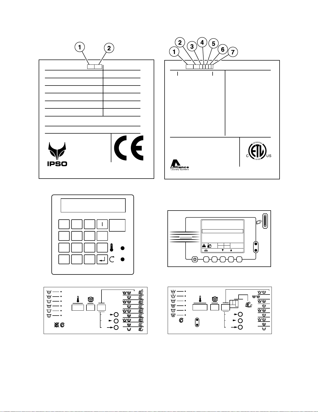
Serial Plate Location
When calling or writing about your product, be
sure to mention model and serial numbers. Model
and serial numbers are located on serial plate(s).
For technical assistance, call the number listed
below:
(920) 748-3121 Ripon, Wisconsin
D0244
© Copyright, Alliance Laundry Systems LLC – DO NOT COPY or TRANSMIT
3
Page 6

Notes
4
© Copyright, Alliance Laundry Systems LLC – DO NOT COPY or TRANSMIT
D0244
Page 7

Model Identification
Information in this manual is applicable to these washer-extractor models:
CWE050AN2
CWE050ANM
CWE050MC2
CWE050MCM
CWE050MD2
CWE050MDM
CWE050ME2
CWE050MEM
CWE050ML2
CWE050MLM
CWE050MN2
CWE050MNM
CWE050MX2
CWE050MXM
CWE050MY2
CWE050MYM
CWE234AN2
CWE234MC2
CWE234MD2
CWE234ME2
CWE234ML2
CWE234MN2
CWE234MX2
CWE234MY2
IWE050AN2
IWE050ANM
IWE050MC2
IWE050MCM
IWE050MD2
IWE050MDM
IWE050ME2
IWE050MEM
IWE050ML2
IWE050MLM
IWE050MN2
IWE050MNM
IWE050MX2
IWE050MXM
IWE050MY2
IWE050MYM
IWE050SC2
IWE050SCM
IWE050SD2
IWE050SDM
IWE050SE2
IWE050SEM
IWE050SL2
IWE050SLM
IWE050SR2
IWE050SRM
IWE050SX2
IWE050SXM
IWE050SY2
IWE050SYM
IWE234AN2
IWE234MC2
IWE234MD2
IWE234ME2
IWE234ML2
IWE234MN2
IWE234MX2
IWE234MY2
IWE234SC2
IWE234SD2
IWE234SE2
IWE234SL2
IWE234SR2
IWE234SX2
IWE234SY2
WE234_CAM-TIMER
WE234_MICRO-20
WE234_PC30
WE234_PS40
WE234_PS40F
WE234_SIGMA
D0244
© Copyright, Alliance Laundry Systems LLC – DO NOT COPY or TRANSMIT
5
Page 8
Washer-Extractor Product Overview
CHM3149P_D0244
PS40
1 2 3
PS40
4 5 6O
7 8 9NO
PROG
+ 0
_
Micro 20
Micro20 Controlled
1
2
3
4
5
6
7
8
9
SELECT
START
ECO.
P
I
E
Sigma
Sigma Controlled
SELECT
ABDC
START
ECO.
P
I
E
1
2
3
4
5
6
7
8
9
Cygnus Professional
CYGNUS
PROFESSIONAL
Normal wash 40º-40ºC
Warm wash 40º-60ºC
Hot wash 40º-90ºC
Delicate 1 90ºC
Synthetic 1
1000
40ºC
1h03
Label 1 Label 2
Alliance International BVBA
Nieuwstraat 146
8560 Wevelgem
Belgium
Tel: +32 56 41 20 54
Fax: +32 56 41 86 74
www.ipso.be
WE234
3 ~ 400V 50Hz
0.55kW 2.5A
9kW 16A
9.55 kW
592 Nm
2007
Type:
Voltage:
Motor:
Heating:
Total:
Kinetic energy:
Manufactured in:
sfc 741837
Water Pressure:
min. 2.07 max. 5.86 Kg/cm²
min. 20.7 max. 58.6 N/cm²
IPX4
07110WD0339
181 kg
73 L
7,3 kg
530 mm
700 rpm
Nr:
Weight:
Capacity:
Dry Load:
Drum:
Speed:
Alliance International BVBA
Made in Belgium
TEL 1-920-748-3121
www.comlaundry.com
100740
CONFORMS TO ANSI/UL
STD 2157
CERTIFIED TO CAN/CSA
STD C22.2 NO.169-94
IPX4
Model No: IW E 05 0 M N M X 10U01
Volts Hertz:
Phase:
Amps:
Recommended
Circuit Breaker:
Interrupt Current:
Motor:
Elec Heat:
Steam
heat:
Serial No: 0710WD0152
208-240 50/60
1 - 3
6 amps
15 amps
10 kA
1 hp
0,75 kW
N/A kW
N/A psi
N/A bar
Typ e:
Capacity:
Water
Pressure:
Max Speed:
Net
Weight:
WFF75
18/ 7 lbs/kg
30-85 psi
2.07-5.86 bar
700 rpm
400 lbs
181 kg
6
© Copyright, Alliance Laundry Systems LLC – DO NOT COPY or TRANSMIT
D0244
Page 9

Washer-Extractor Product Overview
REF PART NO. DESCRIPTION COMMENTS
1 -Product Family CWE
IWE
WE
2 - Capacity 050
234
3 - Control A (PS40F)
CAM-Timer
M (Micro-20)
PC30
PS40
S (Sigma)
4 - Actuation C (Coin Drop Meter)
D (Dual Coin Drop)
E (Electronic Drop)
L (Prep for Remote or Central Pay)
N (Non-Coin)
R (Smart Card Relay)
X (Prep for Coin)
Y (Card Read y)
5 - Speed 2 (Normal Spin)
M (Medium S p i n)
6 - Voltage N (440-480/50-60/3/3)
P (380-415/50-60/3/3)
Q (208-240/50-60/3/3)
X (200-240/50-60/1/3)
7 -Design 1
D0244
© Copyright, Alliance Laundry Systems LLC – DO NOT COPY or TRANSMIT
7
Page 10
Frame
BE000380P_D0244
8
© Copyright, Alliance Laundry Systems LLC – DO NOT COPY or TRANSMIT
D0244
Page 11

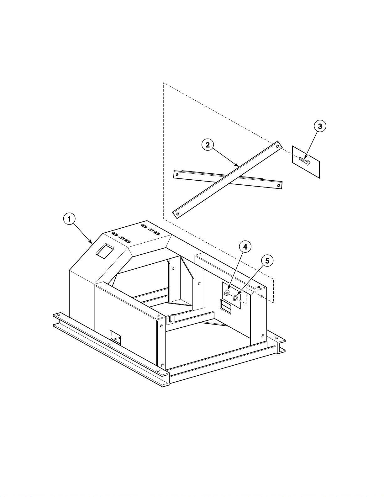
Frame
REF PART NO. DESCRIPTION COMMENTS
1 237/00001/50 Base 36 inches (914 mm) wide; Models without “SL” in the
serial number
1 240/00001/50 Base 34 inches (864 mm) wide; M odels with “SL” in the serial
number
2 137/00003/00 Coin Box
3 206/00003/00 Bolt
4 204/00002/00 Nut
5 203/00001/00 Washer
D0244
© Copyright, Alliance Laundry Systems LLC – DO NOT COPY or TRANSMIT
9
Page 12
Bearing Housing
BE000280AP_D0244
10
© Copyright, Alliance Laundry Systems LLC – DO NOT COPY or TRANSMIT
D0244
Page 13

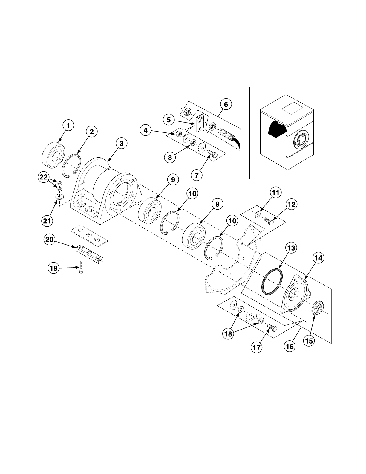
Bearing Housing
REF PART NO. DESCRIPTION COMMENTS
NA KBRGWE234 Bearing Replacement Kit
NA 382P3 Bearing Replacement Tool Kit
1 212/00024/00 Ball Bearing
2 212/00037/00 Retainer Ring
3 212/10104/00 Bearing Housing Assembly
4 204/00009/00 Nut
5 152/00052/00 Speed Detector Assembly Plate
6 209/00400/00 Speed Detector
7 205/00115/00 Bolt
8 201/00007/00 Washer
9 212/00004/00 Ball Bearing
10 212/00006/00 Retainer Ring
11 201/00010/00 Washer
12 205/00101/00 Screw
13 217/00002/00 O-Ring Used with B12327101 Cylinder and Shaft Assembly
14 219/00001/00 Seal Cover Used with B12327101 Cylinder and Shaft Assembly
15 219/00003/00 Shaft Seal Used with B12327101 Cylinder and Shaft Assembly
16 B12333701 Seal Plate Assembly Used with B12380901 Basket (3 mm) and B12381001
Basket (9 mm)
17 205/00102/00 Bolt
18 201/00201/00 Washer
19 206/00045/00 Bolt
20 113/00016/01 U-Piece
21 201/00012/00 Washer
22 204/00001/00 Nut Standard
22 204/00112/00 Nut Lock
D0244
© Copyright, Alliance Laundry Systems LLC – DO NOT COPY or TRANSMIT
11
Page 14
Shell and Basket
BE000390P_D0244
12
© Copyright, Alliance Laundry Systems LLC – DO NOT COPY or TRANSMIT
D0244
Page 15

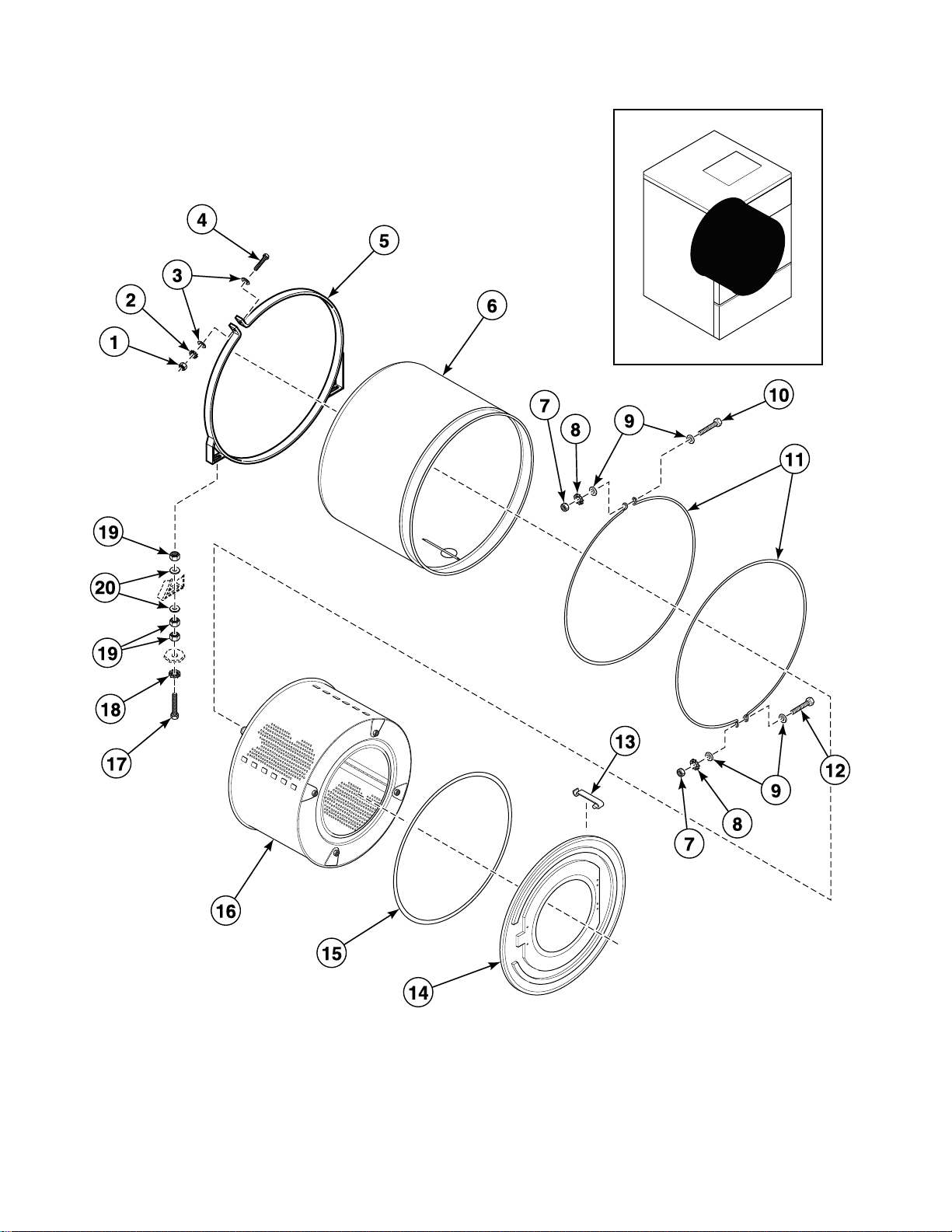
Shell and Basket
REF PART NO. DESCRIPTION COMMENTS
1 204/00003/00 Nut
2 203/00002/00 Washer
3 201/00005/00 Washer
4 206/00052/00 Bolt
5 137/00004/00 Tub Ring Assembly
6 119/00228/00 Outer Tub Electric heat
6 138/00006/00 Outer Tub Steam heat; 2 inlet
6 138/00003/00 Outer Tub Steam heat; 3 inlet
6 138/00008/00 Outer Tub Electric heat; 4 inlet
6 138/00009/00 Outer Tub Steam heat; 4 inlet
6 138/00010/00 Outer Tub 6 inlet
7 204/00005/00 Nut
8 203/00004/00 Washer
9 202/00003/00 Washer
10 206/00011/00 Bolt
11 238/00011/00 Tub Clamp Ring
12 206/00034/00 Bolt
13 217/00008/00 Tub Front Panel Clip
14 138/00001/00 Tub Front
15 223/00242/40 Tub Front Panel Gasket
16 B12543201 Basket Kit Used with 217/00002/00 O-Ring , 119/0001/00 Seal
Plate and 219/00003/00 Shaft Seal
16 B12380901 Basket 3 mm; Used with B12333701 Seal Plate Assembly
16 B12381001 Basket 9 mm; Used with B12333701 Seal Plate Assembly
17 206/00029/00 Bolt
18 203/00001/00 Washer
19 204/00002/00 Nut
20 201/00009/00 Washer
D0244
© Copyright, Alliance Laundry Systems LLC – DO NOT COPY or TRANSMIT
13
Page 16
Basket, Pulley and Belt
BE000387P_D0244
14
© Copyright, Alliance Laundry Systems LLC – DO NOT COPY or TRANSMIT
D0244
Page 17

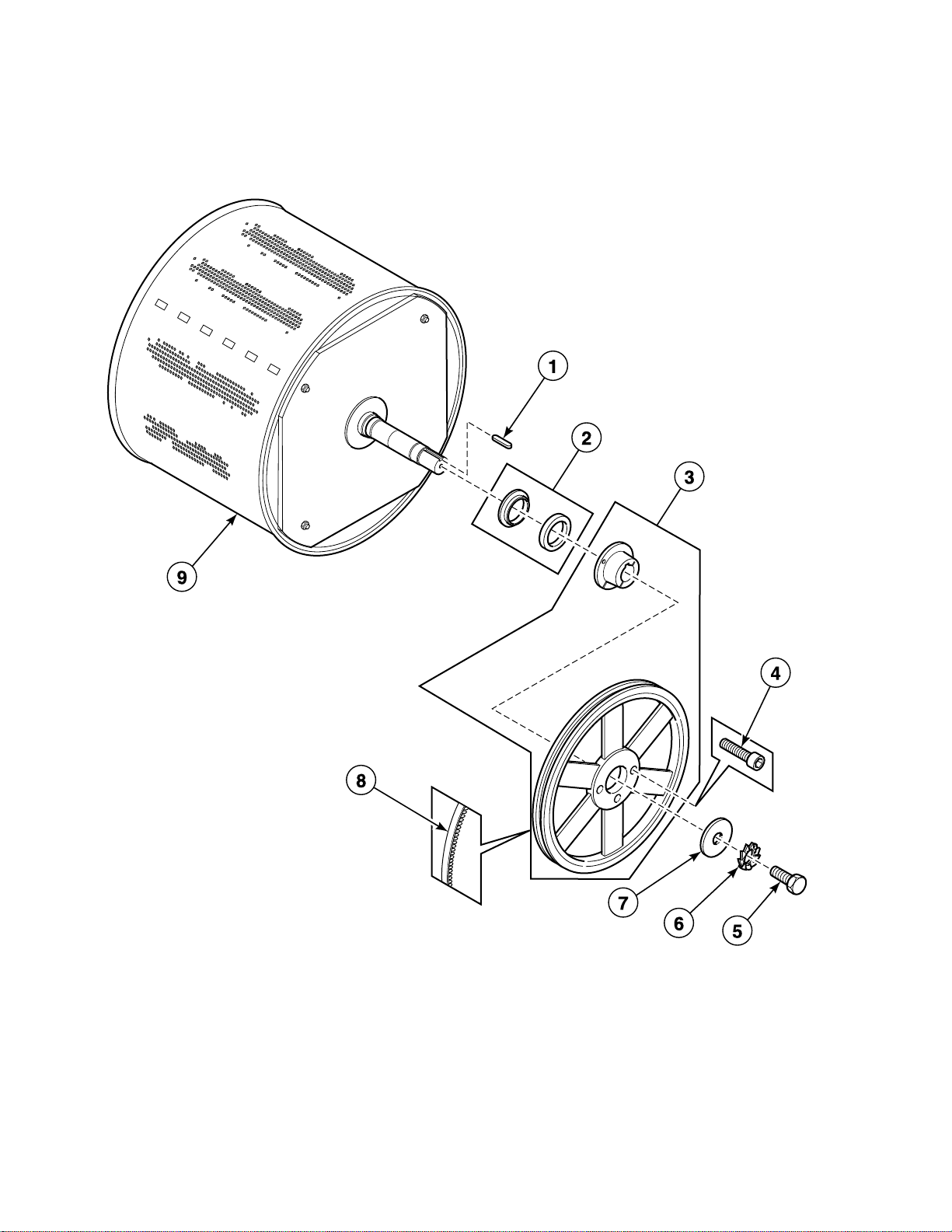
Basket, Pulley and Belt
REF PART NO. DESCRIPTION COMMENTS
1 212/00026/00 Key
2 219/00004/00 Counter Ring
3 239/00013/00 Pulley
4 206/00130/00 Bolt M12 x 45
4 206/00053/00 Screw M12 x 50
5 206/00004/00 Bolt
6 203/00001/00 Washer
7 201/00011/00 Washer
8 226/00028/00 Belt
9 B12543201 Basket Kit Used with 217/00002/00 O-Ring, 119/0001/00 Seal
Plate and 219/00003/00 Shaft Seal
9 B12380901 Basket 3 mm; Used with B12333701 Seal Plate Assembly
9 B12381001 Basket 9 mm; Used with B12333701 Seal Plate Assembly
D0244
© Copyright, Alliance Laundry Systems LLC – DO NOT COPY or TRANSMIT
15
Page 18
Motor with Built-In Tightening Bracket - Models without
BE000381AP_D0244
Inverter Drive
16
© Copyright, Alliance Laundry Systems LLC – DO NOT COPY or TRANSMIT
D0244
Page 19

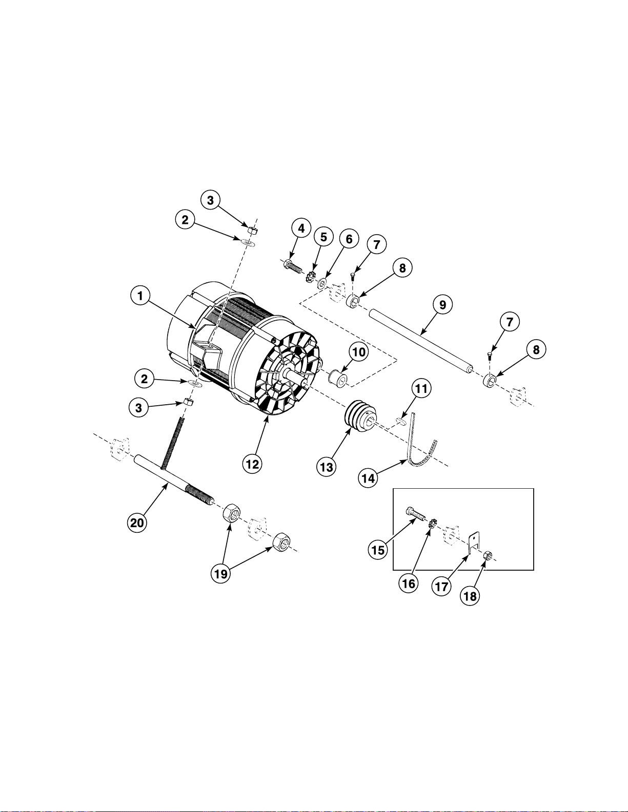
Motor with Built-In Tightening Bracket - Models without
Inverter Drive
REF PART NO. DESCRIPTION COMMENTS
1 141/00005/00 Belt
2 201/00004/00 Washer
3 204/00002/00 Nut
4 206/00006/00 Bolt
5 203/00002/00 Washer
6 201/00010/00 Washer
7 206/00014/00 Bolt
8 226/00054/00 Safety Ring
9 126/00051/00 Spindle
10 223/00087/00 Stopper
11 227/00127/01 Motor Key
12 241/00006/00 Motor 200 Volt/60 Hertz/3 Phase
12 241/00003/00 Motor 208-240 Volt/60 Hertz/3 Phase
12 241/00001/00 Motor 220-380 Volt/50 Hertz/3 Phase
12 241/00004/00 Motor 220-380 Volt/60 Hertz
12 241/00002/00 Motor 400-440 Volt/50 Hertz
13 226/00072/00 Pulley 50 Hertz
13 226/00073/00 Pulley 60 Hertz
14 226/00028/00 Belt
15 207/00008/00 Screw
16 203/00006/00 Washer
17 209/00043/00 Terminal
18 204/00007/00 Nut
19 204/00014/00 Nut
20 137/00002/00 Belt Tightening Piece
D0244
© Copyright, Alliance Laundry Systems LLC – DO NOT COPY or TRANSMIT
17
Page 20
Motor - Models without Inverter Drive
BE000396P_D0244
18
© Copyright, Alliance Laundry Systems LLC – DO NOT COPY or TRANSMIT
D0244
Page 21

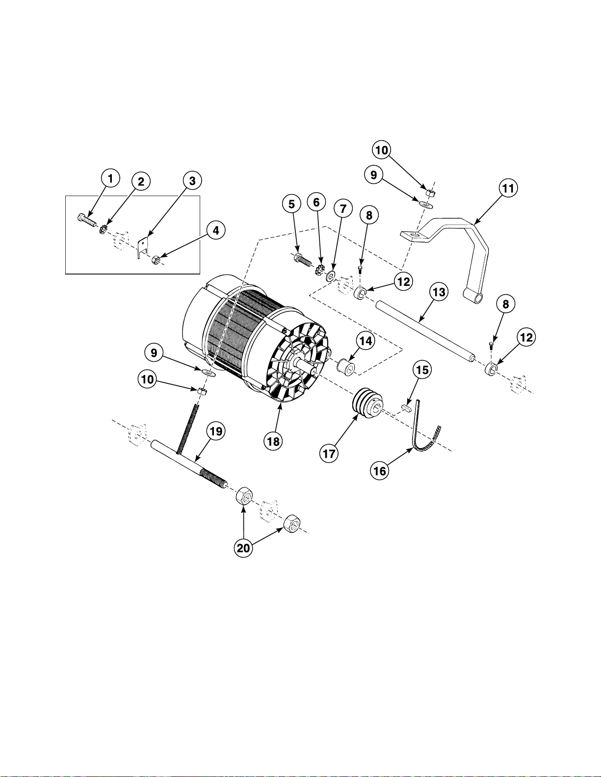
Motor - Models without Inverter Drive
REF PART NO. DESCRIPTION COMMENTS
1 207/00008/00 Screw
2 203/00006/00 Washer
3 209/00043/00 Terminal
4 204/00007/00 Nut
5 206/00006/00 Bolt
6 203/00002/00 Washer
7 201/00010/00 Washer
8 206/00014/00 Bolt
9 201/00004/00 Washer
10 204/00002/00 Nut
11 137/00009/00 Tightening Bracket
12 226/00054/00 Safety Ring
13 126/00051/00 Spindle
14 223/00087/00 Stopper
15 227/00127/01 Motor Key
16 226/00028/00 Belt
17 226/00072/00 Pulley 50 Hertz
17 226/00073/00 Pulley 60 Hertz
18 241/00001/00 Motor
19 137/00002/02 Belt Tightening Piece
20 204/00014/00 Nut
D0244
© Copyright, Alliance Laundry Systems LLC – DO NOT COPY or TRANSMIT
19
Page 22
Motor - Models with Inverter Drive (Drawing 1 of 2)
BE000369AP_D0244
20
© Copyright, Alliance Laundry Systems LLC – DO NOT COPY or TRANSMIT
D0244
Page 23

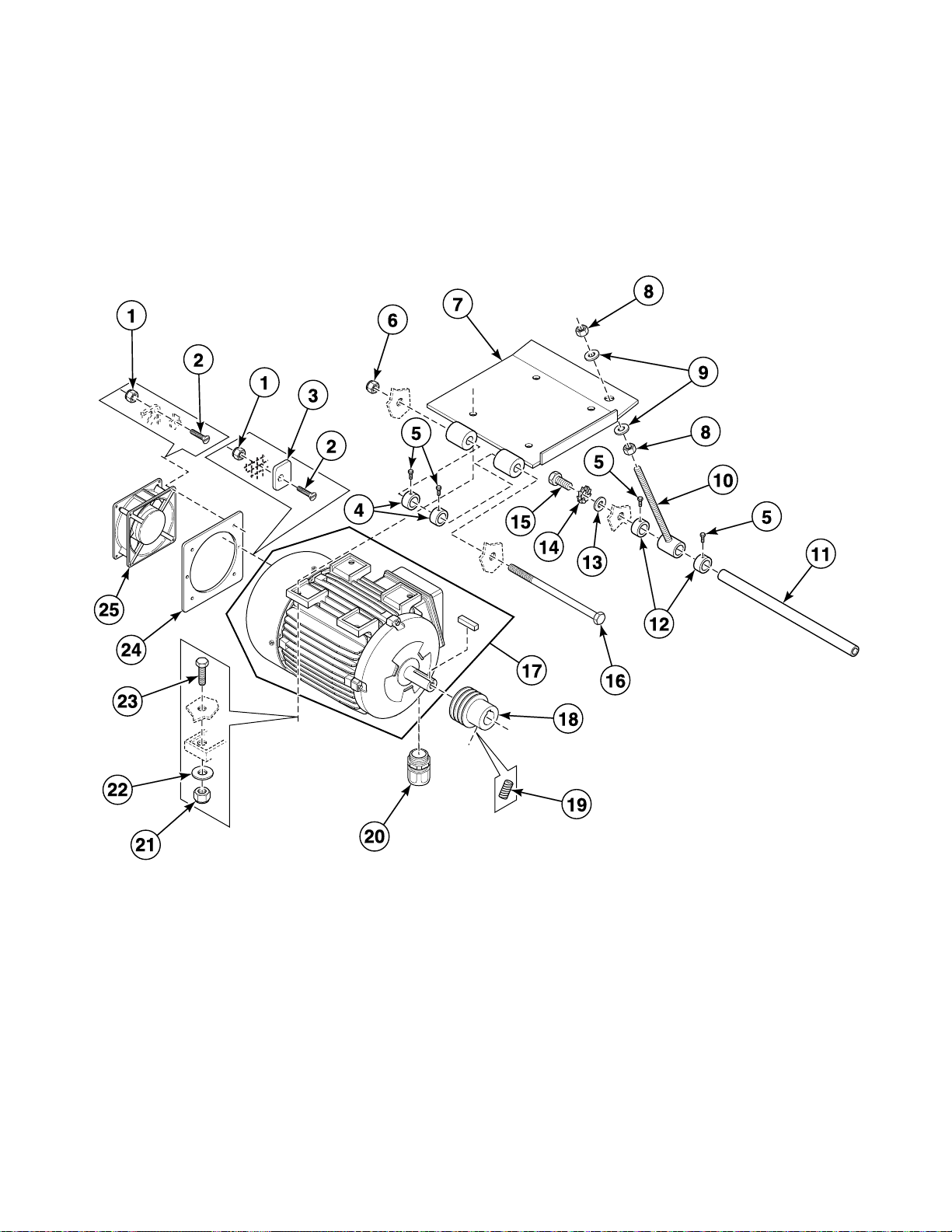
Motor - Models with Inverter Drive (Drawing 1 of 2)
REF PART NO. DESCRIPTION COMMENTS
1 204/00115/00 Nut
2 207/00002/00 Screw
3 117/00042/00 Retaining Ring
4 211/00162/00 Spacer
5 206/00014/00 Bolt
6 204/00113/00 Nut
7 137/00010/00 Mounting Plate
8 204/00012/00 Nut
9 201/00001/00 Washer
10 197/00011/00 Rod
11 126/00051/00 Spindle
12 226/00054/00 Safety Ring
13 201/00010/00 Washer
14 203/00002/00 Washer
15 206/00006/00 Bolt
16 206/00127/00 Bolt
17 B12510701 Motor
18 226/00092/00 Pulley
19 206/00056/00 Screw
20 211/00117/00 Cordlock
21 204/00111/00 Nut
22 201/00004/00 Washer
23 206/00003/00 Bolt
24 111/00243/00 Intermediate Fan Motor Plate
25 209/00287/00 Cooling Fan
D0244
© Copyright, Alliance Laundry Systems LLC – DO NOT COPY or TRANSMIT
21
Page 24
Motor - Models with Inverter Drive (Drawing 2 of 2)
BE000371PA_D0244
22
© Copyright, Alliance Laundry Systems LLC – DO NOT COPY or TRANSMIT
D0244
Page 25

Motor - Models with Inverter Drive (Drawing 2 of 2)
REF PART NO. DESCRIPTION COMMENTS
1 F842121 1 Inverter Drive Kit 200 Vo lt/1 Phas e; Used to convert from 500 to 700 se ries
inverter drive
1 F8421212 Inverter Drive Kit 400 Volt/3 Phas e; Used to convert from 500 to 700 series
inverter drive
1 F8421311 Inverter Drive 200 Volt/1 Phase; 700 series
1 F8421312 Inverter Drive 400 Volt/3 Phase; 700 series
D0244
© Copyright, Alliance Laundry Systems LLC – DO NOT COPY or TRANSMIT
23
Page 26
Drain Plumbing
BE000397P_D0244
24
© Copyright, Alliance Laundry Systems LLC – DO NOT COPY or TRANSMIT
D0244
Page 27

Drain Plumbing
REF PART NO. DESCRIPTION COMMENTS
1 223/00023/00 Hose Clamp
2 223/00183/00 Drain Hose
3 209/00399/00 Drain Valve
4 206/00013/00 Bolt
5 203/00004/00 Washer
6 201/00006/00 Washer
7 204/00005/00 Nut
8 101/00007/00 Outlet Pipe Plate Assembly
9 223/00106/00 Drain Pipe
10 N/A Plate
11 223/00013/00 Hose Clamp
12 223/00100/00 Overflow Hose
N/A = Part no longer available
D0244
© Copyright, Alliance Laundry Systems LLC – DO NOT COPY or TRANSMIT
25
Page 28
Drain Valve
BE000392P_D0244
26
© Copyright, Alliance Laundry Systems LLC – DO NOT COPY or TRANSMIT
D0244
Page 29

Drain Valve
REF PART NO. DESCRIPTION COMMENTS
1 209/00025/08 Screw
2 209/00203/11 Drain Valve Motor 24 Volt
2 209/00052/11 Drain Valve Motor 110 Volt/60 Hertz
2 209/00051/11 Drain Valve Motor 220 Volt/50 or 60 Hertz
3 209/00170/05 Screw
4 209/00203/21 Coil 24 Volt
4 209/00052/21 Coil 115 Volt/60 Hertz
4 209/00051/21 Coil 220 Volt/50 or 60 Hertz
5 209/00399/01 Housing
6 209/00025/10 Drain Valve Shaft Seal
7 209/00025/12 Washer
8 209/00170/10 Drain Valve Shaft
9 209/00025/13 Drain Valve Spring
10 209/00025/08 Screw
11 209/00025/07 Drain Valve Motor Mounting Plate
D0244
© Copyright, Alliance Laundry Systems LLC – DO NOT COPY or TRANSMIT
27
Page 30
Door Lock - Models Through 1997
CHM2989P_D0244
28
© Copyright, Alliance Laundry Systems LLC – DO NOT COPY or TRANSMIT
D0244
Page 31

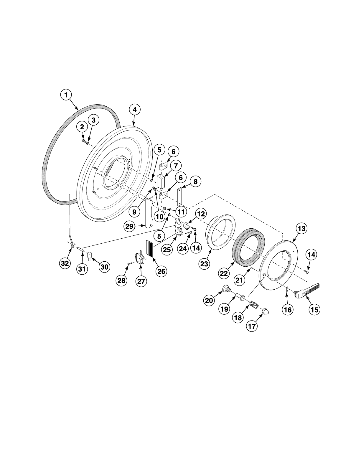
Door Lock - Models Through 1997
REF PART NO. DESCRIPTION COMMENTS
1 223/00242/00 Tub Front Gasket
2 205/00104/00 Bolt
3 202/00101/00 Washer
4 138/00001/00 Tub Front
5 217/00021/00 O-Ring
6 217/00009/02 Door Hinge Assembly
7 217/00009/01 Door Hinge
8 117/00010/00 Door Hinge Spacer
9 204/00106/00 Nut
10 202/00003/00 Washer
11 204/00009/00 Nut
12 217/00017/02 Protection Block
13 118/00125/00 Door
14 207/00102/00 Screw
15 217/00055/00 Door Handle
16 217/00016/00 Door Handle Stop
17 204/00103/00 Nut
18 217/00020/00 Spring
19 211/00105/00 Pin
20 217/00019/00 Holder
21 B12500801 Screw
22 223/00068/00 Door Glass Seal
23 B12449801 Door Glass
24 207/00112/00 Screw
25 217/00017/00 Door Lock Assembly
26 217/00038/00 Insulation Plate
27 209/00023/00 Door Switch
28 207/00109/00 Screw
29 N/A Door Interlock System Protection Plate
30 224/00003/00 Interlock Pin
31 208/00004/00 Pin
32 N/A Lock Wire Bridge
N/A = Part no longer available
D0244
© Copyright, Alliance Laundry Systems LLC – DO NOT COPY or TRANSMIT
29
Page 32

Door Lock - Models Starting 1998
BE000059AP_D0244
30
© Copyright, Alliance Laundry Systems LLC – DO NOT COPY or TRANSMIT
D0244
Page 33

Door Lock - Models Starting 1998
REF PART NO. DESCRIPTION COMMENTS
1 224/00040/00 Lever Spring
2 217/00021/00 O-Ring
3 207/00135/00 Screw
4 210/10015/00 Ground Ter min al
5 203/00007/00 Washer
6 204/00008/00 Nut
7 203/00010/00 Washer
8 207/00112/00 Screw
9 209/00272/00 Door Lock Microswitch
10 201/00018/00 Washer
11 207/00009/00 Screw
12 B12517701 Door Lock Assembly Includes items 1-11, 13-17 and 22-28
13 217/00052/02 Door Lock Pin Kit
14 207/00102/00 Screw
15 217/00017/03 Lock Shaft
16 B12625101 Microswitch
17 209/00274/00 Door Lock Solenoid
18 209/00275/04 Door Lock Board
19 211/00120/00 Standoff
20 203/00006/00 Washer
21 204/00007/00 Nut
22 217/00052/08 Washer
23 224/00049/00 Door Lock Spring
24 217/00052/07 Door Release Wire
25 224/00043/00 Interlock Coil Spring
26 217/00052/04 Interlock Lever
27 217/00052/03 Door Lock Spacer
28 201/00017/00 Washer
D0244
© Copyright, Alliance Laundry Systems LLC – DO NOT COPY or TRANSMIT
31
Page 34

Door
BE000190BP_D0244
32
© Copyright, Alliance Laundry Systems LLC – DO NOT COPY or TRANSMIT
D0244
Page 35

Door
REF PART NO. DESCRIPTION COMMENTS
1 B12449801 Door Glass
2 223/00068/00 Door Glass Seal
3 118/00125/00 Door
4 204/00106/00 Nut
5 111/00003/00 Door Hinge Plate Assembly
6 253/00022/00 Door Hinge Block
7 202/00104/00 Washer
8 118/00124/00 Door Hinge Spacer 2 mm
9 207/00126/00 Screw
10 131/00046/00 Hinge
11 217/00021/00 O-Ring
12 202/00101/00 Washer
13 205/00104/00 Bolt
14 217/00051/00 Door Handle
15 217/00016/00 Door Handle Stop
16 203/00008/00 Washer
17 B12500801 Screw
18 204/00103/00 Nut
19 202/00111/00 Washer
20 211/00109/02 Door Lock Pin Kit
D0244
© Copyright, Alliance Laundry Systems LLC – DO NOT COPY or TRANSMIT
33
Page 36

Door Handle (Drawing 1 of 2)
BE000034AP_D0244
34
© Copyright, Alliance Laundry Systems LLC – DO NOT COPY or TRANSMIT
D0244
Page 37

Door Handle (Drawing 1 of 2)
REF PART NO. DESCRIPTION COMMENTS
1 217/00051/00 Door Handle
2 217/00013/09 Door Mounting Pin
3 217/00013/11 Door Circlip
4 217/00013/12 Door Handle
5 217/00013/13 Door Handle Hook
6 217/00013/14 Door Handle Spring
7 217/00013/15 Door Handle Locking Pin
8 217/00013/16 Door Handle Assembly Plate
9 217/00013/08 Door Locking Pin
10 217/00013/07 Door Locking Grip
11 217/00013/05 Door Axle Roller
12 217/00013/06 Door Roller
13 217/00013/04 Door Handle Latch
14 217/00013/03 Door Lock Spring
15 217/00051/14 Door Handle Latch
D0244
© Copyright, Alliance Laundry Systems LLC – DO NOT COPY or TRANSMIT
35
Page 38

Door Handle (Drawing 2 of 2)
BE000034BP_D0244
36
© Copyright, Alliance Laundry Systems LLC – DO NOT COPY or TRANSMIT
D0244
Page 39

Door Handle (Drawing 2 of 2)
REF PART NO. DESCRIPTION COMMENTS
1 217/00051/00 Door Handle
2 217/00013/09 Door Mounting Pin
3 217/00013/14 Door Handle Spring
4 217/00013/11 Door Circlip
5 217/00013/12 Door Handle
6 217/00051/13 Door Handle Catch
7 217/00051/15 Door Locking Pin
8 217/00013/08 Door Locking Pin
9 217/00013/07 Door Locking Grip
10 217/00013/05 Door Axle Roller
11 217/00013/06 Door Roller
12 217/00013/03 Door Lock Spring
13 217/00051/14 Door Handle Latch
D0244
© Copyright, Alliance Laundry Systems LLC – DO NOT COPY or TRANSMIT
37
Page 40

Control Panel - Micro-20
BE000382P_D0244
1
2
3
4
5
6
7
8
9
S
E
L
E
CT
ST
A
R
T
P
S
E
38
© Copyright, Alliance Laundry Systems LLC – DO NOT COPY or TRANSMIT
D0244
Page 41

Control Panel - Micro-20
REF PART NO. DESCRIPTION COMMENTS
1 229/00262/00 Circuit Board Cover
2 209/00440/02 Printboard 115 Volt
2 209/00440/00 Printboard 230 Volt; Models through 8/31/01
2 209/00440/70 Printboard 230 Volt; Models starting 9/1/01
3 204/00116/00 Nut
4 211/00122/00 Standoff
5 204/00009/00 Nut
6 201/00008/00 Washer
7 229/00255/00 Insulating Sticker
8 111/00221/00 Upper Front Panel Stainless steel
8 111/00184/10 Upper Front Panel Epoxy
9 225/00298/AOL Facia Panel OPL
9 225/00306/AOL Facia Panel Coin
10 225/00309/00 Sticker OPL
10 225/00308/00 Sticker Coin
11 225/00316/00 Plexi Frame
12 209/00248/00 Mushroom Pushbutton
13 209/00520/00 Telem Sticker
14 209/00253/00 Emergency Stop Button Kit
15 209/00099/06 Contact Switch
16 209/00266/01 Eprom
17 209/00439/00 Fuse
D0244
© Copyright, Alliance Laundry Systems LLC – DO NOT COPY or TRANSMIT
39
Page 42

Control Panel - Sigma
BE000375P_D0244
S
E
LECT
A
B
D
C
S
T
A
R
T
E
C
O.
P
I
E
1
2
3
4
5
6
7
8
9
40
© Copyright, Alliance Laundry Systems LLC – DO NOT COPY or TRANSMIT
D0244
Page 43

Control Panel - Sigma
REF PART NO. DESCRIPTION COMMENTS
1 229/00262/00 Circuit Board Cover
2 209/00547/00 Control Board
3 204/00114/00 Nut
4 211/00122/00 Standoff
5 201/00008/00 Washer
6 229/00255/00 Insulating Sticker
7 111/00221/00 Upper Front Panel Stainless steel
7 111/00184/10 Upper Front Panel Epoxy
8 225/00298/AOL Facia Panel OPL
8 225/00306/AOL Facia Panel Coin
9 225/00361/00 Front Label OPL
9 225/00403/00 Decal Coin
9 225/00367/00 Front Label Coin models with central payment
10 210/00902/00 Infrared Cable
11 225/00316/00 Plexi Frame
12 202/00120/00 Metal Disc
13 209/00248/00 Mushroom Pushbutton
14 209/00520/00 Telem Sticker
15 209/00253/00 Emergency Stop Button Kit
16 209/00099/06 Contact Switch
17 209/00439/00 Fuse
D0244
© Copyright, Alliance Laundry Systems LLC – DO NOT COPY or TRANSMIT
41
Page 44

Control Panel - PS40F
BE000554P_D0244
M
I
C
R
O
P
R
O
C
E
S
S
O
R
C
ON
T
R
OL
L
E
R
Pr
o
g
R
u
n
1
4
7
+
2
5
8
0
3
6
9
I
0
N
O
PS4
0
P
R
O
G
42
© Copyright, Alliance Laundry Systems LLC – DO NOT COPY or TRANSMIT
D0244
Page 45

Control Panel - PS40F
REF PART NO. DESCRIPTION COMMENTS
1 229/00262/00 Circuit Board Cover
2 B12351701 Main Board
3 229/00255/00 Insulating Sticker
4 204/00116/00 Nut
5 211/00122/00 Standoff
6 209/00099/26 Contact Switch
7 209/00248/20 Mushroom Pushbutton
8 209/00520/00 Telem Sticker
9 209/00099/25 Switch Base
10 209/00099/29 Switch Knob
11 111/00221/50 Upper Front Panel
12 201/00008/00 Washer
13 209/00552/01 Keypad
14 225/00274/00 Front Panel
15 209/00326/20 Programming Key Contact Switch
16 210/00902/00 Infrared Cable
17 225/00365/00 Overlay
18 202/00120/00 Metal Disc
19 223/00123/00 Washer
20 223/00051/10 Washer
21 204/00116/00 Nut
22 209/00372/01 Fuse
D0244
© Copyright, Alliance Laundry Systems LLC – DO NOT COPY or TRANSMIT
43
Page 46

Control Panel - PS40
BE000368P_D0244
1
4
7
+
2
5
8
0
3
6
9
I
0
N
O
PS4
0
P
R
O
G
M
I
C
R
O
P
R
O
C
E
SS
O
R
C
O
N
T
R
O
L
LE
R
P
r
o
g
R
u
n
Model WE234_PS40
44
© Copyright, Alliance Laundry Systems LLC – DO NOT COPY or TRANSMIT
D0244
Page 47

Control Panel - PS40
REF PART NO. DESCRIPTION COMMENTS
1 111/00218/00 Front Panel
2 209/00099/05 Contact
3 209/00253/00 Emergency Stop Button Kit
4 209/00099/26 Contact Switch
5 209/00099/09 Button
6 209/00520/00 Telem Sticker
7 209/00248/00 Mushroom Pushbutton
8 210/00902/00 Infrared Cable
9 209/00326/00 Programming Switch
10 225/00365/00 Overlay
11 202/00120/00 Metal Disc
12 225/00272/00 Upper Front Panel
13 223/00123/00 Washer
14 223/00051/10 Washer
15 204/00116/00 Nut
16 209/00505/01 Keypad Controller
17 201/00008/00 Washer
18 204/00114/00 Nut
D0244
© Copyright, Alliance Laundry Systems LLC – DO NOT COPY or TRANSMIT
45
Page 48

Control Panel - PC30
BE000388P_D0244
1
4
7
+
2
5
8
0
3
6
9
I
0
N
O
PROG
T
N
O
C
E
ST
A
RT
MI
C
R
O
P
R
O
C
E
S
S
O
R
C
O
N
T
R
O
LL
E
R
P
r
og
R
u
n
46
© Copyright, Alliance Laundry Systems LLC – DO NOT COPY or TRANSMIT
D0244
Page 49

Control Panel - PC30
REF PART NO. DESCRIPTION COMMENTS
1 111/00218/00 Front Panel
2 209/00099/05 Contact
3 209/00253/00 Emergency Stop Button Kit
4 209/00099/26 Contact Switch
5 209/00099/09 Button
6 209/00520/00 Telem Sticker
7 209/00248/00 Mushroom Pushbutton
8 209/00326/00 Programming Switch
9 229/00245/00 Label
10 225/00272/00 Upper Front Panel
11 223/00123/00 Washer
12 223/00051/10 Washer
13 204/00116/00 Nut
14 209/00323/01 Keyboard
15 201/00008/00 Washer
16 204/00114/00 Nut
D0244
© Copyright, Alliance Laundry Systems LLC – DO NOT COPY or TRANSMIT
47
Page 50

Control Panel - 10-Button Mechanical Timer
BE000386P_D0244
48
© Copyright, Alliance Laundry Systems LLC – DO NOT COPY or TRANSMIT
D0244
Page 51

Control Panel - 10-Button Mechanical Timer
REF PART NO. DESCRIPTION COMMENTS
1 209/00275/05 Door Lock Board 115 Volt
1 209/00275/04 Door Lock Board 230 Volt
2 211/00125/00 Printboard Separator
3 208/00024/00 Screw
4 209/00176/00 Selector Switch
5 209/00175/00 Selector Switch
6 204/00007/00 Nut
7 203/00006/00 Washer
8 201/00008/00 Washer
9 211/10156/00 Program Switch Separator
10 207/00032/00 Screw
11 111/00217/01 Front Panel
12 204/00114/00 Nut
13 225/00280/ABL Facia Panel
14 209/00152/00 Lens Cover Red
14 209/00154/00 Lens Cover Orange
15 211/00115/00 Thermostat
16 223/00065/01 Washer
17 223/00065/00 Thermostat Seal
18 209/00151/00 Lamp
19 225/00078/00 Program Indicator
20 225/10023/00 Fastener
21 117/00042/00 Retaining Ring
22 203/00005/00 Washer
23 204/00006/00 Nut
24 202/00003/00 Washer
25 205/00106/00 Bolt
D0244
© Copyright, Alliance Laundry Systems LLC – DO NOT COPY or TRANSMIT
49
Page 52

Control Panel - 5-Button Mechanical Timer
BE000385P_D0244
50
© Copyright, Alliance Laundry Systems LLC – DO NOT COPY or TRANSMIT
D0244
Page 53

Control Panel - 5-Button Mechanical Timer
REF PART NO. DESCRIPTION COMMENTS
1 209/00275/05 Door Lock Board 115 Volt
1 209/00275/04 Door Lock Board 230 Volt
2 209/00281/00 Print Display 120 Volt
2 209/00217/00 Coin Display 220 Volt
3 211/00125/00 Printboard Separator
4 208/00024/00 Screw
5 209/00175/00 Selector Switch
6 204/00007/00 Nut
7 203/00006/00 Washer
8 201/00008/00 Washer
9 211/101 56/ 00 Program Switch Separator
10 207/00032/00 Screw
11 111/00217/02 Front Panel
12 204/00114/00 Nut
13 223/10066/00 Display
14 225/00020/00 Coin Meter Frame
15 225/00319/ABL Facia Panel
16 209/00152/00 Lens Cover Red
16 209/00154/00 Lens Cover Orange
17 209/00151/00 Lamp
18 225/00078/00 Program Indicator
19 225/10023/00 Fastener
20 117/00042/00 Retaining Ring
21 203/00005/00 Washer
22 204/00006/00 Nut
23 202/00003/00 Washer
24 205/00106/00 Bolt
D0244
© Copyright, Alliance Laundry Systems LLC – DO NOT COPY or TRANSMIT
51
Page 54

Electrical Component Mounting Plate - Micro 20 with Inverter Drive
BE000370P_D0244
52
© Copyright, Alliance Laundry Systems LLC – DO NOT COPY or TRANSMIT
D0244
Page 55

Electrical Component Mounting Plate - Micro 20 with Inverter Drive
REF PART NO. DESCRIPTION COMMENTS
1 209/00007/50 Pressure Switch
2 209/00148/02 Contactor LC1D1810M7
2 209/00041/04 Contactor LC1D0901M7; Heating
3 209/00041/04 Contactor
4 209/00264/00 Protector
5 209/00265/00 Protector
6 209/00452/02 Lug Holder
7 209/00279/00 Lock
8 223/00198/00 Grommet
9 206/00101/00 Nut
10 206/00099/00 Bolt
11 140/00021/00 Electrical Component Extension Plate
12 223/00011/00 Hose Clamp
13 223/00015/00 Level Switch Elbow
14 223/00016/00 Hose Barb
15 223/00082/00 Pressure Hose
16 223/00179/10 Pressure Hose
17 225/10004/00 Thermostat Grommet
18 209/00309/02 Thermostat Assembly
19 111/00197/00 Mounting Plate
D0244
© Copyright, Alliance Laundry Systems LLC – DO NOT COPY or TRANSMIT
53
Page 56

Electrical Component Mounting Plate - Micro 20
BE000384P_D0244
without Inverter Drive
54
© Copyright, Alliance Laundry Systems LLC – DO NOT COPY or TRANSMIT
D0244
Page 57

Electrical Component Mounting Plate - Micro 20
without Inverter Drive
REF PART NO. DESCRIPTION COMMENTS
1 206/00099/00 Bolt
2 209/00007/50 Pressure Switch
3 209/00148/02 Contactor LC1D1810M7
3 209/00041/04 Contactor LC1D0901M7; Heating
4 209/00041/04 Contactor LR2-D13109; 4-6A
5 209/00264/00 Protector LR2-D13149; 7-10A
5 209/00265/00 Protector
6 209/00452/01 Printboard
7 209/00452/02 Lug Holder
8 209/00279/00 Lock
9 204/00005/00 Nut
10 201/00007/00 Washer
11 111/00124/00 Mounting Plate
12 223/00198/00 Grommet
13 223/00011/00 Hose Clamp
14 223/00015/00 Level Switch Elbow
15 223/00016/00 Hose Barb
16 223/00082/00 Pressure Hose
17 223/00173/10 Pressure Switch Hose Tee
18 111/00197/00 Mounting Plate
19 209/00309/02 Thermostat Assembly
20 225/10004/00 Thermostat Grommet
D0244
© Copyright, Alliance Laundry Systems LLC – DO NOT COPY or TRANSMIT
55
Page 58

Electrical Component Mounting Plate - Mechanical Timer
BE000383P_D0244
56
© Copyright, Alliance Laundry Systems LLC – DO NOT COPY or TRANSMIT
D0244
Page 59

Electrical Component Mounting Plate - Mechanical Timer
REF PART NO. DESCRIPTION COMMENTS
1 111/00424/00 Pressure Switch Bracket
2 208/00007/00 Screw
3 209/00007/30 Pressure Switch
4 209/00148/02 Contactor LC1D1810M7
4 209/00041/04 Contactor LC1D0901M7; Heating
5 209/00041/04 Contactor
6 209/00452/01 Printboard
7 209/00452/02 Lug Holder
8 209/00264/00 Protector LR2-D13109; 4-6A
8 209/00265/00 Protector LR2-D13149; 7-10A
9 209/00012/00 Reversing Timer 220 Volt/50 Hertz
9 209/00013/00 Reversing Timer 220 Volt/60 Hertz
10 209/00107/00 Timer 220 Volt/50 Hertz
10 209/00107/00 Timer 220 Volt/60 Hertz
11 111/00016/00 Mounting Plate
12 206/00021/00 Screw
13 225/00001/00 Program Indicator
14 206/00099/00 Bolt
15 140/00021/00 Electrical Component Extension Plate
16 223/00011/00 Hose Clamp
17 223/00015/00 Level Switch Elbow
18 223/00016/00 Hose Barb
19 223/00082/00 Pressure Hose
20 201/00006/00 Washer
21 206/00101/00 Nut
22 111/00197/00 Mounting Plate
23 209/00243/00 Thermostat
24 204/00007/00 Nut
25 203/00006/00 Washer
26 207/00008/00 Screw
D0244
© Copyright, Alliance Laundry Systems LLC – DO NOT COPY or TRANSMIT
57
Page 60

Electrical Component Mounting Plate - PC30, PS40 and PS40F
BE000389P_D0244
58
© Copyright, Alliance Laundry Systems LLC – DO NOT COPY or TRANSMIT
D0244
Page 61

Electrical Component Mounting Plate - PC30, PS40 and PS40F
REF PART NO. DESCRIPTION COMMENTS
1 206/00099/00 Bolt
2 111/00175/01 Cover Plate
3 209/00148/02 Contactor
4 209/00041/04 Contactor
5 209/00264/00 Protector LR2-D13109; 4-6A
5 209/00265/00 Protector LR2-D13149; 7-10A
6 209/00452/01 Printboard
7 209/00452/02 Lug Holder
8 209/00279/00 Lock
9 209/00323/02 Printboard Model WE234_PC30
9 209/00505/02 Printboard Model WE234_PS40; 230 Volt
9 209/00542/02 Printboard Model WE234_PS40; 115 Volt
10 204/00116/00 Nut
11 223/00123/00 Washer
12 206/00141/00 Separator
13 203/00007/00 Washer
14 207/00135/00 Screw
15 204/00007/00 Nut
16 203/00006/00 Washer
17 207/00008/00 Screw
18 209/00005/00 Terminal Block
19 223/00174/00 Grommet
20 246/00092/00 Gasket
21 223/00198/00 Grommet
22 206/00105/00 Nut
23 223/00011/00 Hose Clamp
24 223/00210/00 Pressure Switch Elbow
25 225/10004/00 Thermostat Grommet
26 209/00266/08 Thermostat
27 252/00032/00 Filter
28 223/00016/00 Hose Barb
29 223/00212/00 Pressure Switch Hose
30 223/00173/10 Pressure Switch Hose Tee
31 223/00203/00 Grommet
32 111/00256/00 Electrical Component Assembly
33 209/00007/50 Pressure Switch
D0244
© Copyright, Alliance Laundry Systems LLC – DO NOT COPY or TRANSMIT
59
Page 62

Coin Vault
BE000042P_D0244
60
© Copyright, Alliance Laundry Systems LLC – DO NOT COPY or TRANSMIT
D0244
Page 63

Coin Vault
REF PART NO. DESCRIPTION COMMENTS
1 206/00033/00 Bolt
2 211/00070/01 Outer Cabinet Lock
3 211/00070/02 Washer
4 211/00070/04 Spring
5 211/00070/03 Inner Coin Box
6 203/00004/00 Washer
7 204/00005/00 Nut
8 211/00071/00 Coin Box
9 207/00009/00 Screw
10 203/00007/00 Washer
11 209/00060/12 Coin Drop Microswitch
12 204/00008/00 Nut
13 207/00108/00 Screw
14 209/00396/00 Pushbutton
15 211/00100/00 Outer Coin Box
16 111/00100/00 Coin Box Ring Assembly
17 111/00066/00 Coin Box Ring
18 211/00065/02 Coin Box Key
19 211/00065/00 Coin Box Lock
20 111/00068/00 Front Plate
21 211/00101/00 Coin Box
22 211/00065/01 Nut
23 206/00038/00 Screw
24 111/00069/00 Spindle
25 208/00013/00 Roll Pin
26 208/00007/00 Screw
D0244
© Copyright, Alliance Laundry Systems LLC – DO NOT COPY or TRANSMIT
61
Page 64

Coin Meter (Drawing 1 of 2)
BE000042PA_D0244
62
© Copyright, Alliance Laundry Systems LLC – DO NOT COPY or TRANSMIT
D0244
Page 65

Coin Meter (Drawing 1 of 2)
REF PART NO. DESCRIPTION COMMENTS
1 209/00389/00 Coin Meter .10 euro
1 209/00388/00 Coin Meter .20 euro
1 209/00387/00 Coin Meter .50 euro
1 209/00390/00 Coin Meter 1 euro
1 209/00391/00 Coin Meter 1 euro (LVN)
1 209/00119/00 Coin Meter .50 and .20 euro
1 209/00120/00 Coin Meter 1 and .20 euro
1 209/00166/00 Coin Meter 1 and .50 euro
1 209/00576/00 Coin Meter 2 and .50 euro
1 209/00111/00 Coin Meter $0.25
1 209/00111/10 Coin Meter $0.25; Laundercenter
1 209/00215/00 Coin Meter .25 Hfl and 1 Hfl
1 209/00414/00 Coin Meter Canada; .25 and 1.00
1 209/00214/00 Coin Meter .25 Hfl
1 209/00378/00 Coin Meter Australia; 1 and 2
1 209/00229/00 Coin Meter Australia; 1 and .20
1 209/00403/00 Coin Meter 1 fim and 5 fim
1 209/00065/00 Coin Meter Hong Kong; 1
1 209/00418/00 Coin Meter Malaysia; 1
1 209/00364/00 Coin Meter U.K.; 1 pound and 20 pence
1 209/00437/00 Coin Meter 1 rand and 2 rand
1 209/00442/00 Coin Meter 1 shekel and 5 shekel
1 209/00375/00 Coin Meter Singapore; 1
1 209/00383/00 Coin Meter New Zealand; 2 and 1
1 209/00500/00 Coin Meter 5 Mdh and 10 Mdh
1 209/00404/00 Coin Meter 5 NoCr and 10 NoCr
1 209/00215/01 Coin Meter 1 Hfl
1 209/00402/08 Coin Meter 10 dek and 2 dek
1 209/00460/00 Coin Meter 2 dek
1 209/00064/00 Coin Meter Australia; .20
1 209/10215/00 Coin Meter 5 Hfl and 1 Hfl
1 209/00415/00 Coin Meter Hong Kong; 5
1 209/00501/00 Coin Meter 50 kronur and 100 kronur
1 209/00402/01 Coin Meter Token; .800
1 209/00402/03 Coin Meter Token
1 209/00402/07 Coin Meter Token; Wash Club
1 209/00428/00 Coin Meter Token; Custruzione
1 209/00502/00 Coin Meter Token; Small Mueller
1 209/00402/04 Coin Meter Token; Prinz; 28 x 2.7 mm
1 209/00402/02 Coin Meter Token; Prinz; 22.85 x 2.1 mm
1 209/00407/00 Coin Meter Token; Prinz; 26 x 2.05 mm
D0244
© Copyright, Alliance Laundry Systems LLC – DO NOT COPY or TRANSMIT
63
Page 66

Coin Meter (Drawing 2 of 2)
BE000042PA_D0244
64
© Copyright, Alliance Laundry Systems LLC – DO NOT COPY or TRANSMIT
D0244
Page 67

Coin Meter (Drawing 2 of 2)
REF PART NO. DESCRIPTION COMMENTS
1 209/00469/00 Coin Meter Electronic coin meter; NRI
1 209/00216/00 Coin Meter 100 yen
1 209/00278/00 Coin Meter 100 yen and 500 yen
1 209/00373/00 Coin Meter 500 won
1 209/00522/00 Coin Meter Trenner
1 209/00060/00 Coin Drop Token; 5K
1 209/00061/00 Coin Meter Token; 7K
1 209/00068/00 Coin Meter Token; 10K
1 209/00069/00 Coin Meter Token; 12K
1 209/00070/00 Coin Meter Token; 15K
1 209/00122/00 Coin Meter Token; Boissevain
1 209/00411/00 Coin Meter Token; Carsen
1 209/00156/00 Coin Meter Token; Gettone per
1 209/00121/00 Coin Meter Profiled token
1 209/00062/00 Coin Meter Token; Vasketeria
1 209/00161/00 Coin Meter 1 dek
1 209/00158/00 Coin Meter 1 rail
1 209/00160/00 Coin Meter 5 dek
1 209/00269/00 Coin Meter 100 won and 500 won
1 209/00286/00 Coin Meter Token; Blanc Club Lavage
1 209/00296/00 Coin Meter Token; Clean Wash
1 209/00123/00 Coin Meter Token; Jessernigg
1 209/00162/00 Coin Meter Token; Vasketeria and 5 DK
1 209/00066/00 Coin Meter Token; Vasketeria and 2 x 1 DK
1 209/00072/00 Coin Meter Token; Wascator
1 209/00553/00 Coin Meter U.S.; $1.00 and .25
1 209/00548/00 Coin Meter 100 pesetas and 25 pesetas
D0244
© Copyright, Alliance Laundry Systems LLC – DO NOT COPY or TRANSMIT
65
Page 68

Right Side, Front, Lower Rear and Top Panels
BE000379P_D0244
66
© Copyright, Alliance Laundry Systems LLC – DO NOT COPY or TRANSMIT
D0244
Page 69

Right Side, Front, Lower Rear and Top Panels
REF PART NO. DESCRIPTION COMMENTS
1 140/00045/01 Top Panel Stainless steel
1 140/03045/01 Top Panel Epoxy
1 140/00045/02 Top Panel Stainless steel with loc k
2 223/00103/04 Soap Dispenser Cover Hinge Rod 2 required
3 223/00103/01 Soap Dispenser Cover
4 207/00131/00 Bolt
5 223/00103/03 Soap Dispenser Frame
6 208/00104/00 Nut
7 140/00007/00 Side Panel Stainless steel
7 140/03007/00 Side Panel Epoxy
8 206/00099/00 Bolt
9 204/00107/00 Nut
10 111/00002/00 Hook
11 203/00005/00 Washer
12 206/00016/00 Bolt
13 140/00006/01 Front Panel Coin; Stainless steel
13 140/00006/02 Front Panel OPL; Stainless steel
13 140/03006/01 Front Panel Coin; Epoxy
14 111/00001/00 Hook
15 201/00007/00 Washer
16 204/00106/00 Nut
17 140/00009/00 Rear Panel
D0244
© Copyright, Alliance Laundry Systems LLC – DO NOT COPY or TRANSMIT
67
Page 70

Left Side, Lower Front and Upper Back Panels
BE000378P_D0244
68
© Copyright, Alliance Laundry Systems LLC – DO NOT COPY or TRANSMIT
D0244
Page 71

Left Side, Lower Front and Upper Back Panels
REF PART NO. DESCRIPTION COMMENTS
1 111/01158/80 Upper Back Panel
2 111/10102/00 Dispenser Rear Mounting Plate
3 111/10101/00 Dispenser Front Mounting Plate
4 206/00101/00 Nut
5 206/00099/00 Bolt
6 205/00106/00 Bolt
7 202/00110/00 Washer
8 117/00042/00 Retaining Ring
9 203/00005/00 Washer
10 204/00107/00 Nut
11 208/00009/00 Washer
12 207/00101/00 Screw
13 140/00008/00 Lower Panel Stainless steel
13 140/03008/00 Lower Panel Epoxy
14 140/00007/00 Side Panel Stainless steel
14 140/03007/00 Side Panel Epoxy
15 205/00105/00 Bolt M6 x 20
15 205/00103/00 Bolt M6 x 25
16 203/00004/00 Washer
17 111/00063/00 Mounting Plate
18 204/00106/00 Nut
19 206/00027/00 Bolt
20 202/00004/00 Washer
21 204/00114/00 Nut
22 208/00001/00 Screw
23 208/00002/00 Nut
D0244
© Copyright, Alliance Laundry Systems LLC – DO NOT COPY or TRANSMIT
69
Page 72

Upper Back Panel (Drawing 1 of 2)
BE000374P_D0244
70
© Copyright, Alliance Laundry Systems LLC – DO NOT COPY or TRANSMIT
D0244
Page 73

Upper Back Panel (Drawing 1 of 2)
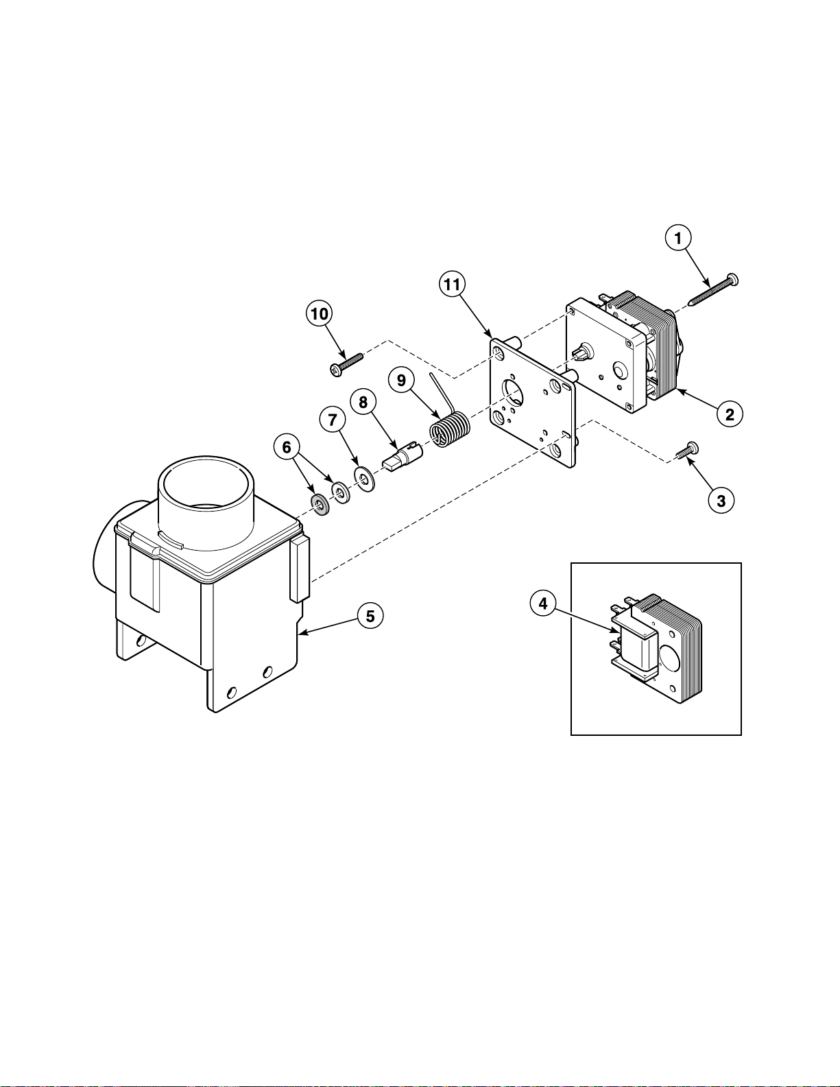
REF PART NO. DESCRIPTION COMMENTS
1 204/00007/00 Nut
2 204/00006/00 Nut
3 207/00031/00 Screw
4 209/00058/00 Terminal Block
5 203/00006/00 Washer
6 211/00120/00 Standoff
7 209/00218/03 Printboard
8 209/00006/01 Ground Terminal
9 209/00202/00 Fuse Holder
10 209/00468/00 Fuse
11 206/00027/00 Bolt
12 223/00198/00 Grommet
13 111/00094/10 Electrical Connection Plate
14 205/00113/00 Bolt
15 202/00004/00 Washer
16 111/01158/80 Upper Back Panel
17 209/00540/00 Network Connection Printboard
18 111/00188/04 Electrical Connection Plate
19 208/00017/00 Rivet
20 209/00099/06 Contact Switch
21 209/00253/00 Emergency Stop Button Kit
22 209/00248/00 Mushroom Pushbutton
23 209/00520/00 Telem Sticker
24 229/00068/02 Electrical Connection Sticker
D0244
© Copyright, Alliance Laundry Systems LLC – DO NOT COPY or TRANSMIT
71
Page 74

Upper Back Panel (Drawing 2 of 2)
BE000373P_D0244
72
© Copyright, Alliance Laundry Systems LLC – DO NOT COPY or TRANSMIT
D0244
Page 75

Upper Back Panel (Drawing 2 of 2)
REF PART NO. DESCRIPTION COMMENTS
1 111/01158/30 Backbridge
2 206/00027/00 Bolt
3 203/00006/00 Washer
4 202/00004/00 Washer
5 204/00007/00 Nut
6 223/00014/00 Hose Clamp
7 223/00160/00 Liquid Soap Hose
8 223/00102/07 Hose Vent
9 209/00419/00 2-Way Inlet Valve Standard thread; Used with F380939 Valve Repair Kit
9 209/0 0316/00 2-Way Inlet Valve Metric thread; Used wit h F380939 Valve Repair Kit
10 223/00011/00 Hose Clamp
11 223/00059/00 Water Hose
12 223/00044/00 Water Hose
13 223/00010/00 Hose Clamp
14 211/00123/00 Cordlock
15 211/00138/00 Cordlock
16 204/00201/00 Nut
17 201/00002/00 Washer
18 111/00198/01 Assembly Plate Support
19 206/00101/00 Nut
20 206/00099/00 Bolt
21 223/00001/04 Prewash and Mainwash Nozzle
D0244
© Copyright, Alliance Laundry Systems LLC – DO NOT COPY or TRANSMIT
73
Page 76

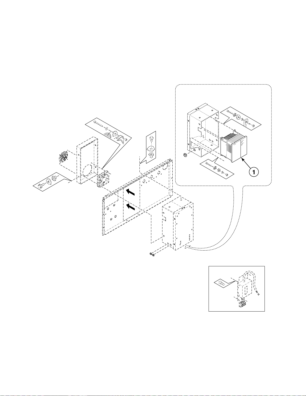
Inverter Drive
BE000371P_D0244
74
© Copyright, Alliance Laundry Systems LLC – DO NOT COPY or TRANSMIT
D0244
Page 77

Inverter Drive
REF PART NO. DESCRIPTION COMMENTS
NA F8410901 Parameter Unit Assembly Inverter mounted; Used with 500-series inverter drives
NA 227/00171/00 Parameter Unit Assembly Hand held
1 209/00287/01 Fan Grill
2 111/01158/11 Inverter Box Cover
3 206/00136/00 Bolt
4 202/00004/00 Washer
5 204/00114/00 Nut
6 206/00099/00 Bolt
7 207/00031/00 Screw
8 203/00006/00 Washer
9 204/00007/00 Nut
10 F8421211 Inverter Drive Kit 200 Volt/1 Phase; U sed to conv ert from 500 to 7 00 series
inverter drive; Includes F8421311 Inverter Drive,
F8409501 Mounting Plate Assem bly an d F4309 03 Screw
10 F8421212 Inverter Drive Kit 400 Volt/3 Phase; U sed to conv ert from 500 to 7 00 series
inverter drive; Includes F8421312 Inverter Drive,
F8409501 Mounting Plate Assem bly an d F4309 03 Screw
10 F8421311 Inverter Drive 200 Volt/1 Phase; 700 series
10 F8421312 Inverter Drive 400 Volt/3 Phase; 700 series
11 223/00174/00 Grommet
12 111/01149/00 Inverter Drive Box
13 227/00165/00 Noise Filter
14 207/00004/00 Screw
15 111/01158/30 Backbridge
16 209/00287/00 Cooling Fan
N/A = Part no longer available
D0244
© Copyright, Alliance Laundry Systems LLC – DO NOT COPY or TRANSMIT
75
Page 78

Supply Dispenser - Mo dels Through 12/31/92 with
CHM2990P_D0244
1.5 Inch Supply Dispenser Hose
76
© Copyright, Alliance Laundry Systems LLC – DO NOT COPY or TRANSMIT
D0244
Page 79

Supply Dispenser - Models Through 12/31/92 with
1.5 Inch Supply Dispenser Hose
REF PART NO. DESCRIPTION COMMENTS
1 223/00044/00 Water Hose
2 223/00010/00 Hose Clamp
3 204/00201/00 Nut
4 201/00002/00 Washer
5 223/00001/07 Washer
6 223/00003/00 Lid Seal
7 223/00001/06 Mounting Plate
8 B12347501 Screw
9 223/00001/04 Prewash and Mainwash Nozzle
10 223/00001/05 Injector
11 223/00001/03 Separator Plate
12 223/00001/01 Soap Dispenser
13 223/00013/00 Hose Clamp
14 223/00007/00 Hose
D0244
© Copyright, Alliance Laundry Systems LLC – DO NOT COPY or TRANSMIT
77
Page 80

Supply Dispenser - *Models Through 12/31/92 with
CHM2991P_D0244
4 Inch Supply Dispenser Hose
78
© Copyright, Alliance Laundry Systems LLC – DO NOT COPY or TRANSMIT
D0244
Page 81

Supply Dispenser - *Models Through 12/31/92 with
4 Inch Supply Dispens er Hose
REF PART NO. DESCRIPTION COMMENTS
1 223/00160/00 Liquid Soap Hose
2 223/00014/00 Hose Clamp
3 223/00102/07 Hose Vent
4 223/00107/01 Ventilating Hose
5 223/00109/00 Soap Dispenser Gasket
6 223/00102/40 Exterior Box
7 223/00102/06 Soap Spray Nozzle
8 223/00102/05 Softener Spray Nozzle
9 223/00102/03 Rinse Insert
10 223/00102/04 Soap Dispenser Rinse Siphon
11 B12347501 Screw
12 223/00102/08 Liquid Soap Dispenser Insert
13 223/00115/00 Hose
14 223/00023/00 Hose Clamp
15 223/00009/00 Clamp
16 223/00059/00 Water Hose 20 mm diameter
17 223/00188/00 Hose 25 mm diameter
18 223/00013/00 Hose Clamp
19 204/00105/00 Nut
20 203/00008/00 Washer
21 207/00106/00 Screw
D0244
© Copyright, Alliance Laundry Systems LLC – DO NOT COPY or TRANSMIT
79
Page 82

Supply Dispenser - Models Starting 1/1/93
CFD440P_D0244
80
© Copyright, Alliance Laundry Systems LLC – DO NOT COPY or TRANSMIT
D0244
Page 83

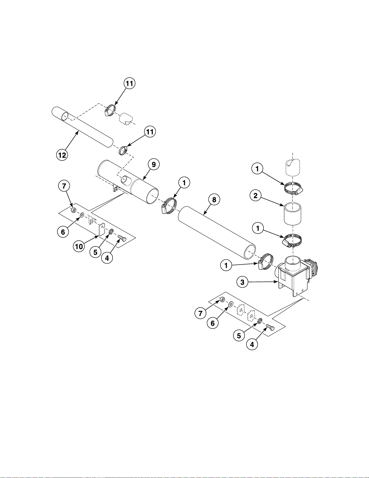
Supply Dispenser - Models Starting 1/1/93
REF PART NO. DESCRIPTION COMMENTS
1 223/00014/00 Hose Clamp
2 223/00107/04 Hose Vent
3 223/00109/00 Soap Dispenser Ga sk et
4 223/00102/70 Soap Dispenser Includes pipe
4 223/00102/40 Exterior Box
5 B12347501 Screw
6 223/00102/06 Soap Sp ray Nozzl e
7 123/00107/00 Anti-Splash Plate Sigma models
7 123/00103/06 Soap Box Assembly Plate All other models
8 223/00196/00 Dispenser Drain Funnel
9 223/00102/04 Soap Dispenser Rinse Siph on
10 223/00102/08 Liquid Soap Dispenser Insert
11 223/00102/03 Rinse Insert
12 223/00102/05 Softener Spray Nozzle
13 223/00220/00 Soap Dispenser Hose
14 223/00071/00 Hose Clamp
15 223/00011/00 Hose Clamp
16 223/00010/00 Hose Clamp
17 223/00059/00 Water Hose
18 223/00044/00 Water Hose
D0244
© Copyright, Alliance Laundry Systems LLC – DO NOT COPY or TRANSMIT
81
Page 84

Micro 20 Control Panel Decal (Drawing 1 of 5)
BE000398P_D0244
1
2
3
4
5
6
7
8
9
S
E
LEC
T
S
T
A
R
T
P
S
E
82
© Copyright, Alliance Laundry Systems LLC – DO NOT COPY or TRANSMIT
D0244
Page 85

Micro 20 Control Panel Decal (Drawing 1 of 5)
REF PART NO. DESCRIPTION COMMENTS
1 225/00366/00 Label
1 225/00250/00 Label
1 225/00371/00 Label
1 325/00321/00 Sticker
1 225/00339/00 Label
1 325/00324/00 Label
1 225/00344/00 Label
1 225/00335/00 Label
1 225/00364/00 Label
1 225/00325/00 Label
1 225/00374/00 Label
1 225/00308/00 Sticker
1 225/00341/00 Sticker
1 225/00419/00 Sticker
1 225/00342/00 Label
1 225/00310/00 Label
1 225/00351/00 Label
1 225/00345/00 Label
1 225/00386/00 Sticker
1 225/00349/00 Label
1 225/00309/00 Sticker
1 225/00382/00 Label
1 225/00385/00 Label
1 225/00311/00 Label
1 225/00387/00 Sticker
1 225/00352/00 Label
1 325/00323/00 Label
1 225/00363/00 Label
1 225/00343/00 Label
1 225/00304/00 Front Panel
D0244
© Copyright, Alliance Laundry Systems LLC – DO NOT COPY or TRANSMIT
83
Page 86

Micro 20 Control Panel Decal (Drawing 2 of 5)
1
2
3
4
5
6
7
8
9
S
E
LEC
T
S
T
A
R
T
P
S
E
BE000398PA_D0244
84
© Copyright, Alliance Laundry Systems LLC – DO NOT COPY or TRANSMIT
D0244
Page 87

Micro 20 Control Panel Decal (Drawing 2 of 5)
REF PART NO. DESCRIPTION COMMENTS
1 225/10132/00 Front Label
1 225/10158/00 Front Label
1 325/00239/00 Front Label
1 225/10228/00 Front Label
1 225/10129/00 Front Label
1 225/10063/00 Front Label
1 325/10095/00 Front Label
1 225/10045/00 Front Label
1 225/10032/00 Front Label
1 225/10033/00 Front Label
1 225/10231/00 Front Label
1 325/10087/00 Front Label
1 225/10064/00 Front Label
1 225/10176/00 Front Label
1 225/10210/00 Front Label
1 225/10101/00 Front Label
1 225/10038/00 Front Label
1 225/10100/00 Front Label
1 225/10249/00 Front Label
1 225/10248/00 Front Label
1 225/10193/00 Front Label
1 325/10091/00 Front Label
1 225/10072/00 Front Label
1 225/10153/00 Front Label
1 225/10042/00 Front Label
1 225/10089/00 Front Label
1 225/10243/00 Front Label
1 225/10168/00 Front Label
1 225/10071/00 Front Label
1 225/10229/00 Front Label
1 225/10043/00 Front Label
1 225/10044/00 Front Label
1 225/10177/00 Front Label
1 325/10102/00 Front Label
1 225/10065/00 Front Label
D0244
© Copyright, Alliance Laundry Systems LLC – DO NOT COPY or TRANSMIT
85
Page 88

Micro 20 Control Panel Decal (Drawing 3 of 5)
1
2
3
4
5
6
7
8
9
SE
LE
C
T
S
T
A
R
T
P
S
E
BE000398PB_D0244
86
© Copyright, Alliance Laundry Systems LLC – DO NOT COPY or TRANSMIT
D0244
Page 89

Micro 20 Control Panel Decal (Drawing 3 of 5)
REF PART NO. DESCRIPTION COMMENTS
1 229/00257/00 Front Label
1 225/10161/00 Front Label
1 225/10200/00 Front Label
1 225/10164/00 Front Label
1 225/10201/00 Front Label
1 225/10194/00 Front Label
1 225/10109/00 Front Label
1 225/10128/00 Front Label
1 225/10114/00 Front Label
1 225/10126/00 Front Label
1 225/10195/00 Front Label
1 225/10127/00 Front Label
1 225/10110/00 Front Label
1 225/10125/00 Front Label
1 225/10159/00 Front Label
1 225/10111/00 Front Label
1 225/10124/00 Front Label
1 225/10162/00 Front Label
1 225/10112/00 Front Label
1 225/10049/00 Front Label
1 225/10202/00 Front Label
1 225/10102/00 Front Label
1 225/10050/00 Front Label
1 225/10113/00 Front Label
1 225/10103/00 Front Label
1 225/10203/00 Front Label
1 225/10055/00 Front Label
1 225/10051/00 Front Label
1 225/10204/00 Front Label
1 225/10052/00 Front Label
1 225/10104/00 Front Label
1 225/10199/00 Front Label
1 225/10053/00 Front Label
1 225/10105/00 Front Label
1 225/10157/00 Front Label
1 225/10106/00 Front Label
1 225/10246/00 Front Label
1 225/10115/00 Front Label
1 225/10107/00 Front Label
1 225/10056/00 Front Label
1 225/10233/00 Front Label
D0244
© Copyright, Alliance Laundry Systems LLC – DO NOT COPY or TRANSMIT
87
Page 90

Micro 20 Control Panel Decal (Drawing 4 of 5)
1
2
3
4
5
6
7
8
9
SE
LE
C
T
S
T
A
R
T
P
S
E
BE000398PB_D0244
88
© Copyright, Alliance Laundry Systems LLC – DO NOT COPY or TRANSMIT
D0244
Page 91

Micro 20 Control Panel Decal (Drawing 4 of 5)
REF PART NO. DESCRIPTION COMMENTS
1 225/10232/00 Front Label
1 225/10108/00 Front Label
1 225/10244/00 Front Label
1 225/10160/00 Front Label
1 225/10131/00 Front Label
1 225/10116/00 Front Label
1 225/10245/00 Front Label
1 225/10121/00 Front Label
1 225/10074/00 Front Label
1 225/10067/00 Front Label
1 225/10075/00 Front Label
1 225/10073/00 Front Label
1 225/10090/00 Front Label
1 225/10068/00 Front Label
1 225/10080/00 Front Label
1 225/10097/00 Front Label
1 225/10069/00 Front Label
1 225/10145/00 Front Label
1 225/10087/00 Front Label
1 225/10134/00 Front Label
1 225/10093/00 Front Label
1 225/10182/00 Front Label
1 225/10081/00 Front Label
1 225/10135/00 Front Label
1 225/10082/00 Front Label
1 225/10098/00 Front Label
1 225/10183/00 Front Label
1 225/10136/00 Front Label
1 225/10083/00 Front Label
1 225/10184/00 Front Label
1 225/10137/00 Front Label
1 225/10241/00 Front Label
1 225/10185/00 Front Label
1 225/10138/00 Front Label
1 225/10242/00 Front Label
1 225/10178/00 Front Label
1 225/10123/00 Front Label
1 225/10230/00 Front Label
1 225/10198/00 Front Label
1 225/10152/00 Front Label
1 225/10179/00 Front Label
D0244
© Copyright, Alliance Laundry Systems LLC – DO NOT COPY or TRANSMIT
89
Page 92

Micro 20 Control Panel Decal (Drawing 5 of 5)
1
2
3
4
5
6
7
8
9
SE
LE
C
T
S
T
A
R
T
P
S
E
BE000398PB_D0244
90
© Copyright, Alliance Laundry Systems LLC – DO NOT COPY or TRANSMIT
D0244
Page 93

Micro 20 Control Panel Decal (Drawing 5 of 5)
REF PART NO. DESCRIPTION COMMENTS
1 225/10154/00 Front Label
1 225/10180/00 Front Label
1 225/10155/00 Front Label
1 225/10181/00 Front Label
1 225/10156/00 Front Label
1 225/10219/00 Front Label
1 225/10220/00 Front Label
1 225/10221/00 Front Label
1 225/10222/00 Front Label
1 225/10223/00 Front Label
1 225/10224/00 Front Label
1 225/10226/00 Front Label
1 225/10227/00 Front Label
1 225/10205/00 Front Label
1 225/10206/00 Front Label
1 225/10207/00 Front Label
1 225/10208/00 Front Label
1 225/10209/00 Front Label
1 225/10146/00 Front Label
1 225/10148/00 Front Label
1 225/10150/00 Front Label
1 225/10147/00 Front Label
1 225/10149/00 Front Label
1 225/10151/00 Front Label
1 225/10169/00 Front Label
1 225/10170/00 Front Label
1 225/10171/00 Front Label
1 225/10172/00 Front Label
1 225/10173/00 Front Label
1 225/10174/00 Front Label
1 225/10175/00 Front Label
1 225/10196/00 Front Label
1 225/10235/00 Front Label
1 225/10236/00 Front Label
1 225/10237/00 Front Label
1 225/10238/00 Front Label
1 225/10239/00 Front Label
1 225/10240/00 Front Label
1 225/10250/00 Front Label
1 225/10251/00 Front Label
1 225/10247/00 Front Label
D0244
© Copyright, Alliance Laundry Systems LLC – DO NOT COPY or TRANSMIT
91
Page 94

Mechanical Timer Control Panel Decal (Drawing 1 of 2)
BE000400P_D0244
92
© Copyright, Alliance Laundry Systems LLC – DO NOT COPY or TRANSMIT
D0244
Page 95

Mechanical Timer Control Panel Decal (Drawing 1 of 2)
REF PART NO. DESCRIPTION COMMENTS
1 225/10132/00 Front Label
1 225/10158/00 Front Label
1 325/00239/00 Front Label
1 225/10228/00 Front Label
1 225/10129/00 Front Label
1 225/10063/00 Front Label
1 325/10095/00 Front Label
1 225/10045/00 Front Label
1 225/10032/00 Front Label
1 225/10033/00 Front Label
1 225/10231/00 Front Label
1 325/10087/00 Front Label
1 225/10064/00 Front Label
1 225/10176/00 Front Label
1 225/10210/00 Front Label
1 225/10101/00 Front Label
1 225/10038/00 Front Label
1 225/10100/00 Front Label
1 225/10249/00 Front Label
1 225/10248/00 Front Label
1 225/10193/00 Front Label
1 325/10091/00 Front Label
1 225/10072/00 Front Label
1 225/10153/00 Front Label
1 225/10042/00 Front Label
1 225/10089/00 Front Label
1 225/10243/00 Front Label
1 225/10168/00 Front Label
1 225/10071/00 Front Label
1 225/10229/00 Front Label
1 225/10043/00 Front Label
1 225/10044/00 Front Label
1 225/10177/00 Front Label
1 325/10102/00 Front Label
1 225/10065/00 Front Label
D0244
© Copyright, Alliance Laundry Systems LLC – DO NOT COPY or TRANSMIT
93
Page 96

Mechanical Timer Control Panel Decal (Drawing 2 of 2)
BE000400PA_D0244
94
© Copyright, Alliance Laundry Systems LLC – DO NOT COPY or TRANSMIT
D0244
Page 97

Mechanical Timer Control Panel Decal (Drawing 2 of 2)
REF PART NO. DESCRIPTION COMMENTS
1 225/00066/00 Label
1 225/10009/00 Label
1 225/00068/00 Label
1 225/10010/00 Label
1 225/00069/00 Label
1 225/10011/00 Label
1 225/00070/00 Label
1 225/00084/00 Label
1 225/00085/00 Label
1 225/00071/00 Label
1 225/00086/00 Label
1 225/10012/00 Label
1 225/00072/00 Label
1 225/00073/00 Label
1 225/10013/00 Label
1 225/10024/00 Label
1 225/10026/00 Label
1 225/10014/00 Label
1 225/10025/00 Label
1 225/10017/00 Label
1 225/10018/00 Label
1 225/10019/00 Label
1 225/10094/00 Label
1 225/10020/00 Label
1 225/10021/00 Label
1 225/10022/00 Label
1 225/10028/00 Label
1 225/10005/00 Label
1 225/10006/00 Label
1 225/10007/00 Label
D0244
© Copyright, Alliance Laundry Systems LLC – DO NOT COPY or TRANSMIT
95
Page 98

Electric and Steam Heating
BE000391P_D0244
96
© Copyright, Alliance Laundry Systems LLC – DO NOT COPY or TRANSMIT
D0244
Page 99

Electric and Steam Heating
REF PART NO. DESCRIPTION COMMENTS
1 209/00563/30 Heating Element 2000W; 220/240 Volt
1 209/00049/00 Heating Element 3000W; 220/240 Volt
1 209/00581/00 Heating Element 4000W; 380 Volt
2 209/00189/00 Steam Valve
3 119/00087/00 Steam Injector
4 204/00004/00 Bolt
5 202/00002/00 Washer
6 203/00003/00 Washer
7 206/00009/00 Bolt
8 131/00008/00 Mounting Plate
9 206/00035/00 Bolt
10 F360202 Heating Element Plug
D0244
© Copyright, Alliance Laundry Systems LLC – DO NOT COPY or TRANSMIT
97
Page 100

Soap Pump - Knight
BE000050AP_D0244
98
© Copyright, Alliance Laundry Systems LLC – DO NOT COPY or TRANSMIT
D0244
 Loading...