

Page 1
Installation Instructions
for Stacked Dryers
Inside ......................................
Dimensions ........................................................................ 3
Before You Start ................................................................ 4
Installing the Dryer ............................................................ 5
Installer Checklist .............................................................. Back Cover
Para bajar una copia de estas instrucciones en espafiol, visite www.speedqueen.com.
Keep these instructions for future reference.
(If this machine changes ownership, this manual must accompany machine.)
Date Purchased
Model Number
Serial Number
www.speedqueen.com
Part No. 512063R3
June 2007
Page 2
WARNING
FOR YOUR SAFETY, the information in this manual must be followed to minimize the risk of
fire or explosion or to prevent property damage, personal injury or death.
° Do not store or use gasoline or other flammable vapors and liquids in the vicinity of this or
any other appliance.
° WHAT TO DO IF YOU SMELL GAS:
- Do not try to light any appliance.
- Do not touch any electrical switch; do not use any phone in your building.
- Clear the room, building or area of all occupants.
- Immediately call your gas supplier from a neighbor's phone. Follow the gas supplier's
instructions.
- If you cannot reach your gas supplier, call the fire department.
• Installation and service must be performed by a qualified installer, service agency or the gas
supplier.
W033
WARNING
FOR YOUR SAFETY
Do not store or use gasoline or other flammable vapors and liquids in the vicinity of this or any
other appliance.
W053
The following information applies to the state of Massachusetts, USA.
• This appliance can only be installed by a Massachusetts licensed plumber or gas fitter.
• This appliance must be installed with a 36 inch (91 cm) long flexible gas connector.
• A "T-Handle" type gas shut-off valve must be installed in the gas supply line to this appliance.
• This appliance must not be installed in a bedroom or bathroom.
(OCopyright 2007, Alliance Laundry Systems LLC
All rights reserved. No part of the contents of this book may be reproduced or transmitted in any form or by any
means without the expressed written consent of the publisher.
2 © Copyright, Alliance Laundry Systems LLC - DO NOT COPY or TRANSMIT 512063
Page 3
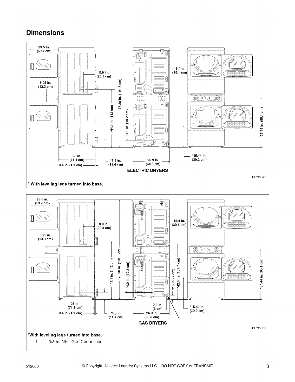
Dimensions
23.5 in.
(59.7 cm)
5.25 in.
(13.3 cm)
!
I
i
i
J
j lifT',
...... I;%_.j
8.0 in.
(20.3 cm)
g_
O4
15.4 in.
-(39.1 cm)
g
° °i..... i° °
O4
c;
l'l
0.4 in. (1.1 cm)
* With leveling legs turned into base.
I_ 23.5 in.
(59.7 cm) --
i i'
(20.3 cm)
5.25 in.
(13.3 cm)
I
1
t *4.5 in.
8.0 in.
(11.4 cm)
L
(68.3 cm)
ELECTRIC DRYERS
O3
l
15.44 in.
(39.2 cm)
DRY2212N
15.4 in.
(39.1 cm)
\ ¢:
_ S" \\
28 in.
(71.1 cm)
0.4 in. (1.1 cm)
*With leveling legs turned into base.
1 3/8 in. NPT Gas Connection
512063 © Copyright, Alliance Laundry Systems LLC - DO NOT COPY or TRANSMIT 3
e-_,_
2.3 in.
-- 26.9 in.
(6 (39.2 cm)
(68.3 cm) 1
GAS DRYERS
"15.44 in.
1
DRY2213N
Page 4
Before You Start
Parts Included
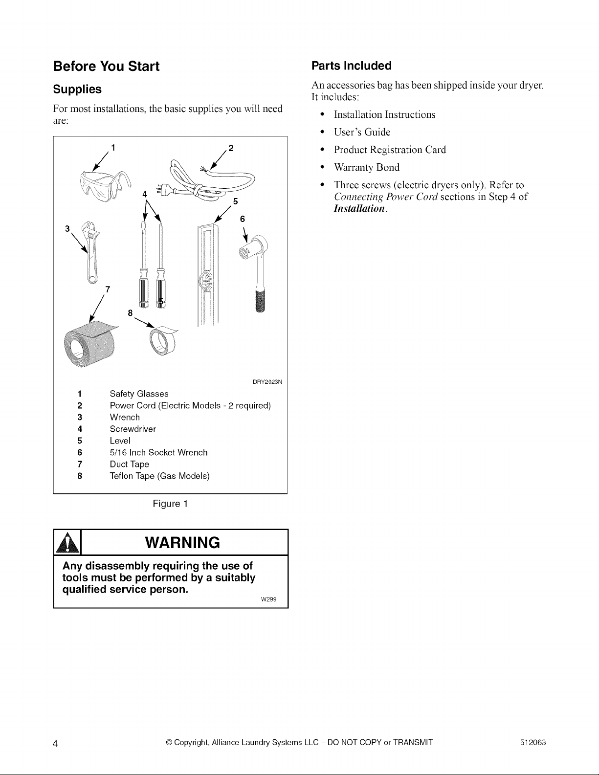
Supplies
For most installations, the basic supplies you will need
are:
2
4
/.
8
An accessories bag has been shipped inside your dryer.
It includes:
• Installation Instructions
• User's Guide
• Product Registration Card
• Warranty Bond
• Three screws (electric dryers only). Refer to
Connecting Power Cord sections in Step 4 of
Installation.
1
2
3
4
5
6
7
8
Safety Glasses
Power Cord (Electric Models - 2 required)
Wrench
Screwdriver
Level
5/16 Inch Socket Wrench
Duct Tape
Teflon Tape (Gas Models)
Figure 1
WARNING
Any disassembly requiring the use of
tools must be performed by a suitably
qualified service person.
DRY2023N
W299
4 © Copyright, Alliance Laundry Systems LLC - DO NOT COPY or TRANSMIT 512063
Page 5
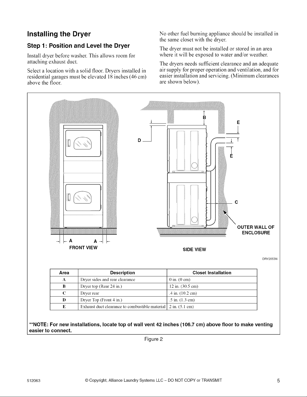
Installing the Dryer
Step 1" Position and Level the Dryer
Install dryer before washer. This allows room for
attaching exhaust duct.
Select a location with a solid floor. Dryers installed in
residential garages must be elevated 18 inches (46 cm)
above the floor.
No other fuel burning appliance should be installed in
the same closet with the dryer.
The dryer must not be installed or stored in an area
where it will be exposed to water and/or weather.
The dryers needs sufficient clearance and an adequate
air supply for proper operation and ventilation, and for
easier installation and servicing. (Minimum clearances
are shown below).
t
B
E
i i
ENCLOSURE
A A
FRONT VIEW
Area Description Closet Installation
A Dryer sides and rear clearance 0 in. (0 cm)
B Dryer top (Rear 24 in.) 12 in. (30.5 cm)
C Dryer rear .4 in. (10.2 cm)
D Dryer Top (Front 4 in.) .5 in. (1.3 cm)
E Exhaust duct clearance to combustible material 2 in. (5.1 cm)
**NOTE: For new installations, locate top of wall vent 42 inches (106.7 cm) above floor to make venting
easier to connect.
SIDE VIEW
DRY2053N
Figure 2
512063 © Copyright, Alliance Laundry Systems LLC - DO NOT COPY or TRANSMIT 5
Page 6

Place the dryer in position, and adjust the legs until the
dryer is level from side to side and front to back. The
dryer must not rock.
2
1
DRY2059N
1
2
3
Dryer Base
Level
Leveling Leg
WARNING
This gas appliance contains or produces a
chemical or chemicals which can cause
death or serious illness and which are
known to the State of California to cause
cancer, birth defects, or other reproductive
harm. To reduce the risk from substances in
the fuel or from fuel combustion, make sure
this appliance is installed, operated, and
maintained according to the instructions in
this manual.
Wl15
To reduce the risk of fire, DO NOT use
plastic or thin foil ducting to exhaust the
dryer.
W354
• DO NOT use plastic or thin foil ducting. Rigid
metal duct is recommended.
Figure 3
IMPORTANT: In mobile home installations, gas
dryers MUST be permanently attached to the floor
at the time of installation. Order No. 526P3 Dryer
Installation Kit (available at extra cost) for a
manufactured (mobile) home installation. Follow
the instructions supplied with the kit.
Step 2: Connect Dryer Exhaust System
WARNING
To reduce the risk of fire and combustion
gas accumulation the dryer MUST be
exhausted to the outdoors.
W604
To reduce the risk of fire and the
accumulation of combustion gases, DO NOT
exhaust dryer air into a window well, gas
vent, chimney or enclosed, unventilated
area, such as an attic, wall, ceiling, crawl
space under a building or concealed space
of a building.
W045
L!Li i
DO
• Locate dryer so exhaust duct is as short as
possible.
• Be certain old ducts are cleaned before installing
your new dryer.
• Use 4 inch (102 mm) diameter rigid or flexible
metal duct.
• The male end of each section of duct must point
away from the dryer.
• Use as few elbows as possible.
• Use duct tape or pop-rivets on all duct joints.
Y//////////////////////,,
DON'T
DRY2010N
Figure 4
• Ductwork that runs through unheated areas must
be insulated to help reduce condensation and lint
build-up on pipe walls.
6 © Copyright, Alliance Laundry Systems LLC - DO NOT COPY or TRANSMIT 512063
Page 7

• In mobile home installations, dryer exhaust duct
must be secured to mobile home structure.
• Dryer exhaust duct MUST NOT terminate under
mobile home.
Dryer exhausts 220 cfm (measured at back of
dryer).
Static pressure in exhaust duct should not be
greater than .6 inches water column (1.5 cm),
measured with manometer placed on exhaust
duct two feet (61 cm) from dryer (check with
dryer running and no load).
Exhaust Direction
The dryer can be exhausted to the outdoors through the
back, left, right or bottom of the dryer. EXCEPTION:
Gas dryers cannot be vented out the left side
because of the burner housing.
Dryer is shipped from factory ready for rear exhaust.
Exhausting the dryer through sides or bottom can be
accomplished by installing a Directional Exhaust Kit,
528P3, available as optional equipment at extra cost.
Exhaust System
Exhausting dryer in hard-to-reach locations can
be done by installing 521 P3 Flexible Metal Vent
Kit (available as optional equipment at extra
cost).
Failure to exhaust dryer properly will void
warranty.
NOTE: Venting materials are not supplied with the
dryer (obtain locally).
For best drying results, recommended maximum
length of exhaust system is shown in Table 1.
To prevent backdraft when dryer is not in operation,
outer end of exhaust pipe must have a weather hood
with hinged dampers (obtain locally).
NOTE: Weather hood should be installed at least
12 inches (30.5 cm) above the ground. Larger
clearances may be necessary for installations where
heavy snowfall can occm:
Number of Weather HoodType
90° Elbows Recommended Use Onlyfor Short Run installations
4 in. 4 in.
(10.2 cm) (10.2 cm)
Maximum length of 4 in. (10.2 cm)diameter rigid metal duct.
0 65 feet (19.8 m) 55 feet (16.8 m)
1 55 feet (16.8 m) 47 feet (14.3 m)
2 47 feet (14.3 m) 41 feet (12.5 m)
3 36 feet (11.0 m) 30 feet (9.1 m)
4 28 feet (8.5 m) 22 feet (6.7 m)
Maximum length of 4 in. (10.2 cm) diameter flexible metal duct.
0 feet (13.7 m)
1 feet (10.7 m)
2 feet (9.1 m)
3 feet (7.6 m)
4 20 feet (6.1 m)
NOTE: Deduct 6 feet (1.8 m) for each additional elbow.
45 35 feet (10.7 m)
35 27 feet (8.2 m)
30 21 feet (6.4 m)
25 17 feet (5.2 m)
D6731
Table 1
2-1/2 in.
(6.35 cm)
15 feet (4.5 m)
D8021
512063 © Copyright, Alliance Laundry Systems LLC - DO NOT COPY or TRANSMIT 7
Page 8

Step 3: (Gas Dryer Only) Connect Gas
Supply Pipe
WARNING
To reduce the risk of gas leaks, fire or
explosion:
• The dryer must be connected to the type
of gas as shown on nameplate located in
the door recess.
• Use a new flexible stainless steel
connector.
• Use pipe joint compound insoluble in L.P.
(Liquified Petroleum) Gas, or Teflon tape,
on all pipe threads.
• Purge air and sediment from gas supply
line before connecting it to the dryer.
Before tightening the connection, purge
remaining air from gas line to dryer until
odor of gas is detected. This step is
required to prevent gas valve
contamination.
• Do not use an open flame to check for gas
leaks. Use a non-corrosive leak detection
fluid.
• Any disassembly requiring the use of
tools must be performed by a suitably
qualified service person.
W316
Natural Gas Altitude Adjustments
Altitude
feet m
3000 915
6000 1830
8000 2440
9000 2740
10,000 3050
Orifice Size
No. inches mm
43 0.0890 2.26
44 0.0860 2.18
45 0.0820 2.08
46 0.0810 2.06
47 0.0785 1.99
Part No.
503778
58719
503779
503780
503781
Table 2
.
Remove the shipping cap from the gas
connection at the rear of the dryer. Make sure you
do not damage the pipe threads when removing
the cap.
3. Connect to gas supply pipe.
NOTE: When connecting to a gas line, an
equipment shut-off valve must be installed within
6 feet (1.8 m) of the dryel. An 1/8 in. NPT pipe plug
must be installed as shown for checking inlet
pressure. Refer to Figure 5.
1
.
Make certain your dryer is equipped for use with
the type of gas in your laundry room. Dryer is
equipped at the factory for Natural Gas with a
3/8 inch NPT gas connection.
NOTE: The gas service to a gas dryer must
conform with the local codes and ordinances, or in
the absence of local codes and ordinances, with the
latest edition of the National Fuel Gas Code ANSI
Z223.1/NFPA 54 or the CAN/CGA-B149, National
Gas Installation Code.
Natural Gas, 1000 Btu/ft 3 (37.3 MJ/m 3) service must
be supplied at 6.5 + 1.5 inch water column pressure.
For proper operation at altitudes above 3000 feet
(915 m) the natural gas valve spud orifice size must be
reduced to ensure complete combustion. Refer to
Table 2.
3
D6991
New stainless steel flexible connector -
(Use design CSA certified connector)
Use only if allowed by local codes
2
3
4
1/8 in. NPT Pipe Plug
Equipment Shut-Off Valve
Black Iron Pipe Shorter than 20 ft. (6.1 m) -
Use 3/8 in. (9.5 mm) pipe
3/8 in. NPT Gas Connection
Figure 5
8 © Copyright, Alliance Laundry Systems LLC - DO NOT COPY or TRANSMIT 512063
Page 9

.
Tighten all connections securely. Turn on gas and
check all pipe connections (internal & external)
for gas leaks with a non-corrosive leak detection
fluid.
NOTE: The dryer and its appliance main gas valve
must be disconnected from the gas supply piping
system during any pressure testing of that system
at test pressures in excess of 1/2 psi (3.45 kPa).
Refer to Step 8 (Check Heat Source).
L.P. (Liquefied Petroleum) Gas, 2500 Btu/ft 3
(93.1 MJ/m 3) service must be supplied at 10 + 1.5 inch
water column pressure.
For proper operation at altitudes above 3000 feet (915 m)
the L.R gas valve spud orifice size must be reduced to
ensure complete combustion. Refer to Table 3.
L.P. Altitude Adjustments
Altitude
feet m
3000 915
8000 2440
Orifice Size
No. inches mm
55 0.0520 1.32
56 0.0465 1.18
Table 3
Part No.
58755
503786
NOTE: DO NOT connect the dryer to L.P. Gas
Service without converting the gas valve. Install
L.P. Gas Conversion Kit 649P3, available at extra
cost.
Step 4: (Electric Dryer Only) Connect
Electrical Plug
Grounding Information
This dryer must be connected to a grounded
metal, permanent wiring system; or an
equipment-grounding conductor must be run
with the circuit conductors and connected to the
equipment-grounding terminal or lead on the
dryer.
The dryer has its own terminal block that must be
connected to a separate branch, 60 Hertz, single
phase circuit, AC (alternating current) circuit,
fused at 30 Amperes (the circuit must be fused
on both sides of the line). Electrical service for
the dryer should be of maximum rated voltage
listed on the nameplate. Do not connect dryer
to 110, 115, or 120 volt circuit.
Heating elements are available for field
installation in dryers which are to be connected to
electrical service of different voltage than that
listed on nameplate, such as 208 Volt.
If branch circuit to dryer is 15 feet (4.57 m) or
less in length, No. 10 AWG wire (copper wire
only), or as required by local codes. If over 15
feet (4.57 m), use No. 8 AWG wire (copper wire
only), or as required by local codes. Allow
sufficient slack in wiring so dryer can be moved
from its normal location when necessary.
The power cord connection between wall
receptacle and dryer terminal block IS NOT
supplied with dryeL Type of power cord and
gauge of wire must conform to local codes.
Dryer requires 120/240 Volt or 120/208 Volt, 60 Hertz,
3 or 4 wire electrical suppy. Refer to serial plate for
specific electrical requirements.
NOTE: The wiring diagram is located behind the
control panel, inside the control cabinet.
WARNING
To reduce the risk of fire, electric shock,
serious injury or death, all wiring and
grounding MUST conform with the latest
edition of the National Electrical Code,
ANSI/NFPA 70, or the Canadian Electrical
Code, CSA C22.1, and such local
regulations as might apply. It is the
customer's responsibility to have the wiring
and fuses installed by a qualified electrician
to make sure adequate electrical power is
available to the dryer.
512063 © Copyright, Alliance Laundry Systems LLC - DO NOT COPY or TRANSMIT 9
W521
Page 10

Connecting Power Cord with Three-Wire Plug
NOTE: Four-wire cord is required for mobile
homes or where codes do not permit grounding
through neutral.
NOTE: The power cord is NOT supplied with the
electric dryer. Type of power cord and gauge of wire
must conform to local codes and instructions. POWERSUPPLY
The method of wiring the dryer is optional and subject
to local code requirements.
POWER SUPPLY
NOTE: Connect the dryer to the power supply with the
MAXIMUM RATED VOLTAGE listed on the nameplate.
A typical
30-Amp
Three-Wire
Receptacle
NEMAType
10-30R
120 -+
V.A.C.
V.A.C.
±12
V.A.C.
NOTE: Use COPPER WIRE only.
Shorter than 15 ft. (4.5 m) - use 10 AWG
INTERMEDIATE
FUSE BOX (may
be omitted if
service entrance
box is fused)
WALL
RECEPTACLE
POWER CORD CONNECTION DIRECT CONNECTION
Longer than 15 ft. (4.5 m) - use 8 AWG
3 Wire Grounded Neutral 120/240 Volt, 60 Hertz
AC 1 Phase Service Entrance Switch Box
(Refer to NOTE above)
2
3
30 Ampere Fuses or Circuit Breaker
Neutral Wire
2
3_
6
41._._......- 7_
L1 L2 L1 L2
Metallic or Non-Metallic Sheathed Cable
(Copper Wire Only)
5
6
7
Figure 6
Power Cord (Not supplied with dryer)
Neutral
Terminal Block in Dryer
INTERMEDIATE
SHUT-OFF BOX
(may or may not
be fused)
D8161
1. Disconnect power to dryer.
2. Remove access cover from rear of dryer.
D6951
3.
Use a strain relief and insert end of power cord
through power supply hole.
D6961
Figure 8
Figure 7
10 © Copyright, Alliance Laundry Systems LLC - DO NOT COPY or TRANSMIT 512063
Page 11

4. Use the three screws from the accessories bag to
attach the power cord wires to the terminal block.
Refer to Figure 9.
1
Connecting Power Cord with Four-Wire Plug
NOTE: Four-wire cord is required for mobile
homes or where codes do not permit grounding
through neutral.
\
3
1
2
3
5. Tighten all screws firmly.
IMPORTANT: Failure to tighten these screws
firmly may result in wire failure at the terminal
block.
.
Secure the strain relief to the power cord, or
wires, where they enter the dryer cabinet.
.
Check the continuity of the ground connection
before plugging the cord into an outlet. Use an
acceptable indicating device connected to the
center grounding pin of the plug and the green
screw on the back of the cabinet.
"L1" Terminal
Neutral Terminal
"L2" Terminal
Figure 9
D2861
1
/
4"
0
V.A.C.
1 Typical Four-Wire Receptacle
2 Power Cord - Not Supplied with Dryer
3 Strain Relief Nut
4 Strain Relief
Figure 10
1. Disconnect power to dryer.
2. Remove access cover from rear of dryer.
DRY2016N
8. Reinstall access cover and screw.
C
D6951
Figure 11
512063 © Copyright, Alliance Laundry Systems LLC - DO NOT COPY or TRANSMIT 11
Page 12

3. Remove ground screw and save for use in Step 5.
Remove wire and use in Step 6.
1
D6971
Ground Screw
5. Attach power cord ground (green) wire to rear
bulkhead using ground screw removed in Step 3.
Figure 12
.
Use a strain relief and insert end of power cord
through power supply hole.
Figure 13
D6961
DRY1920N
1 White
2 "L2" Terminal
3 Black
4 Green
5 Red
6 Neutral Terminal
7 "LI" Terminal
Figure 14
.
Use the three screws from the accessories bag to
attach the remaining power cord wires to the
terminal block as follows:
a. Red wire to "L 1" terminal.
b. Black wire to "L2" terminal.
c. White wire to Neutral terminal.
NOTE: When installing the white wire, loop the
free eyelet end of the ground wire (removed in
Step 3) and attach along with the white wire to the
neutral (center) terminal on the terminal block.
7. Tighten all screws firmly.
IMPORTANT: Failure to tighten these screws
firmly may result in wire failure at the terminal
block.
.
Secure the strain relief to the power cord, or
wires, where they enter the dryer cabinet.
.
Check the continuity of the ground connection
before plugging the cord into an outlet. Use an
acceptable indicating device connected to the
center grounding pin of the plug and the green
screw on the back of the cabinet.
10. Reinstall access cover and screw.
12 © Copyright, Alliance Laundry Systems LLC - DO NOT COPY or TRANSMIT 512063
Page 13

Step 5: Wipe Out Inside of Dryer
Gas Dryer
Before using dryer for the first time, use an all-purpose
cleaner, or a detergent and water solution, and a damp
cloth to remove shipping dust from inside dryer drum.
DRY2058N
Figure 15
Step 6: Plug In the Dryer
Electric Dryer
Connect the dryer to an electrical power source. Refer
to Step 4 for information on connecting power cord.
Dryer requires 120 Volt, 60 Hertz electrical supply and
comes equipped with a 3-prong grounding plug. Refer
to serial plate for specific electrical requirements.
NOTE: The wiring diagram is located behind the
control panel, inside the control cabinet.
WARNING
To reduce the risk of fire, electric shock,
serious injury or death, all wiring and
grounding MUST conform with the latest
edition of the National Electrical Code,
ANSI/NFPA 70, or the Canadian Electrical
Code, CSA C22.1, and such local
regulations as might apply. It is the
customer's responsibility to have the wiring
and fuses installed by a qualified electrician
to make sure adequate electrical power is
available to the dryer.
W521
When plugging in the dryer:
• Do not overload circuits.
° Do not use an adapter.
° Do not use an extension cord.
• Do not operate both a washer and gas dryer on
the same circuit. Use separetely fused 15 amp
circuits.
The dryer is designed to be operated on a separate
branch, polarized, three-wire, effectively grounded,
120 Volt, 60 Hertz, AC (alternating current) circuit
protected by a 15 Ampere fuse, equivalent fusetron or
circuit breaker.
The three-prong grounding plug on the power cord
should be plugged directly into a polarized three-slot
effectively grounded receptacle rated 120 Volts AC
(alternating current) 15 Amps. Refer to Figure ! 7 to
determine correct polarity of the wall receptacle.
Connect to 30 Amp circuit.
D2751
Figure 16
512063 © Copyright, Alliance Laundry Systems LLC - DO NOT COPY or TRANSMIT 13
Page 14

Grounding Information
The dryer must be grounded. In the event of
malfunction or breakdown, grounding will reduce the
risk of electric shock by providing a path of least
resistance for electric current. The dryer is equipped
with a cord having an equipment-grounding conductor
and a 3 prong grounding plug. The three-prong
grounding plug on the power cord should be plugged
directly into a polarized three-slot effectively
grounded receptacle rated 110/120 Volts AC
(alternating current) 15 Amps.
WARNING
This dryer is equipped with a three-prong
(grounding) plug for your protection against
shock hazard and should be plugged
directly into a properly grounded three-
prong receptacle. Do not cut or remove the
grounding prong from this plug.
W036
WARNING
Improper connection of the equipment-
grounding conductor can result in a risk of
electric shock. Check with a qualified
electrician or service person if you are in
doubt as to whether the dryer is properly
grounded.
W038
Plug cord into separately fused 15 Amp circuit.
DRY2022N
1 "L1"
2 Ground
3 Neutral
4 Neutral Side
5 Round Grounding Prong
Figure 17
Step 7: Recheck Steps 1-6
Do not modify the plug provided with the dryer - if it
will not fit the outlet, have a proper outlet installed by
Refer to Installer Checklist on the back cover of this
manual and make sure that dryer is installed correctly.
a qualified electrician.
Step 8: Check Heat Source
NOTE: Have a qualified electrician check the
polarity of the wall receptacle. If a voltage reading
is measured other than that illustrated, the
qualified electrician should correct the problem.
Do not operate other appliances on the same circuit
when this appliance is operating.
Electric Dryers
Close the loading door and start the dryer in a heat
setting (refer to the Operating Instructions supplied
with the dryer). After the dryer has operated for three
minutes, the exhaust air or exhaust pipe should be
warm.
WARNING
To reduce the risk of an electric shock or
fire, DO NOT use an extension cord or an
adapter to connect the dryer to the electrical
power source,
14 © Copyright, Alliance Laundry Systems LLC - DO NOT COPY or TRANSMIT 512063
W037
Page 15

Gas Dryers
To view the burner flame, remove the lower front
panel of the dryer.
Close the loading door, start the dryer in a heat setting
(refer to the Operating Instructions supplied with the
dryer); the dryer will start, the igniter will glow red
and the main burner will ignite.
IMPORTANT: If all air is not purged out of gas
line, gas igniter may go off before gas is ignited. If
this happens, after approximately two minutes
igniter will again attempt gas ignition.
After the dryer has operated for approximately five
minutes, observe burner flame through lower front
panel. Adjust the air shutter to obtain a soft, uniform
blue flame. (A lazy, yellow-tipped flame indicates lack
of air. A harsh, roaring, very blue flame indicates too
much air.) Adjust the air shutter as follows:
.
Loosen the air shutter lockscrew.
2.
Turn the air shutter to the left to get a luminous
yellow-tipped flame, then turn it back slowly to
the right to obtain a steady, soft blue flame.
.
After the air shutter is adjusted for proper flame,
tighten the air shutter lockscrew securely.
4. Reinstall the lower front panel.
AI WA N,NG
For personal safety, lower front panel must
be in place during normal operation.
After the dryer has operated for approximately three
minutes, exhaust air or exhaust pipe should be warm.
W046
D7021
1
2
Air Shutter Lockscrew
Appliance Main Gas Valve
3
4
Air Shutter
1/8 in. (3.1 mm) Pipe Plug
(For checking manifold pressure)
Figure 18
512063 © Copyright, Alliance Laundry Systems LLC - DO NOT COPY or TRANSMIT 15
Page 16

Installer Checklist
Fast Track for Installing the Unit
(Refer to the manual for more detailed information)
O • Position and
®
LEVEL ®
Level the Dryer.
i
CHECK
O • Connect Dryer Exhaust System.
D2551
D2591
k
CHECK
GAS ONLY
Supply Pipe _ _
i Connect Gas __
Hoses. ___
Check for Gas __
Leaks. __
D2561
0
• Wipe Out Inside of
Dryer.
_ CHECK DRY2058N
Plug In the Dryer.
_ Ga__2541
Electric D2751
CHECK
• Recheck Steps 1-6.
ELECTRIC ONLY
• Connect Electrical Cord.
L
CHECK
CHECK
_ D2581
W3151EOA
1
O
L
_ CHECK
CHECK
Check Heat Source. '_,_
.. J
___ D7021
 Loading...