

Page 1
Tumble Dryers
TMB1282C_SVG
120 Pound (55 Kilogram) Capacity
170 Pound (77 Kilogram) Capacity
200 Pound (90 Kilogram) Capacity
Models with 0 or 3 in 13th Position of Model Number
Refer to Page 8 for Model Identification
Installation
Original Instructions
Keep These Instructions for Future Reference.
CAUTION: Read the instructions before using the machine.
(If this machine changes ownership, this manual must accompany machine.)
www.alliancelaundry.com
Part No. 70532501ENR7
December 2018
Page 2

Page 3
Installation must conform with local codes or, in the absence of
local codes, with:
In the U.S.A., installation must conform to the latest edition of
the American National Standard Z223.1/ NFPA 54 “National
Fuel Gas Code” and Standard ANSI/NFPA 70 “National Electric
Code.”
In Canada, installation must comply with Standards CAN/CSAB149.1 Natural Gas and Propane Installation Code and CSA
C22.1, latest edition, Canadian Electric Code, Part I.
In Australia and New Zealand, installation must comply with the
Gas Installations Standard AS/NZS 5601 Part 1: General Installations.
In Europe, before installation, check that the local distribution
conditions, nature of gas and pressure, and the adjustment of the
appliance are compatible.
This equipment has been designed and certified to comply with
IEC/EN 60335 electrical safety standards for tumble dryers.
Read all instructions before using tumble dryer.
IMPORTANT: If it is unavoidable that fabrics that contain vegetable or cooking oil or have been contaminated by hair care products be placed in a tumble dryer,
they should first be washed in hot water with extra detergent. This will reduce, but not eliminate, the hazard.
WARNING
FOR YOUR SAFETY, the information in this manual
must be followed to minimize the risk of fire or explosion or to prevent property damage, personal injury or death.
W033
WARNING
• Do not store or use gasoline or other flammable
vapors and liquids in the vicinity of this or any
other appliance.
• WHAT TO DO IF YOU SMELL GAS:
• Do not try to light any appliance.
• Do not touch any electrical switch; do not use
any phone in your building.
• Clear the room, building or area of all occu-
pants.
• Immediately call your gas supplier from a
neighbor’s phone. Follow the gas supplier’s instructions.
• If you cannot reach your gas supplier, call the
fire department.
• Installation and service must be performed by a
qualified installer, service agency or the gas supplier.
W052
IMPORTANT: Information must be obtained from a local gas supplier on instructions to be followed if the
user smells gas. These instructions must be posted in
a prominent location. Step-by-step instructions of the
above safety information must be posted in a prominent location near the tumble dryer for customer use.
IMPORTANT: Post the following statement in a prominent location
FOR YOUR SAFETY
Do not store or use gasoline or other flammable vapors
and liquids in the vicinity of this or any other appliance.
DANGER
Electric shock hazard will result in death or serious
injury. Disconnect all electric power to appliance and
accessories and wait five (5) minutes before servicing.
©
Copyright, Alliance Laundry Systems LLC -
DO NOT COPY or TRANSMIT
IMPORTANT: The installer must fully test the tumble
dryer after installation and demonstrate to the owner
how to operate the machine.
IMPORTANT: The machine shall only be installed in a
room separated from inhabited rooms, incorporating
appropriate ventilation specified in the National Installation Regulations.
W925
IMPORTANT: The tumble dryer is not to be used if industrial chemicals have been used for cleaning.
3 Part No. 70532501ENR7
Page 4
WARNING
WARNING
To reduce the risk of electric shock, fire, explosion,
serious injury or death:
• Disconnect electric power to the tumble dryer before servicing.
• Close gas shut-off valve to gas tumble dryer before servicing.
• Close steam valve to steam tumble dryer before
servicing.
• Never start the tumble dryer with any guards/
panels removed.
• Whenever ground wires are removed during servicing, these ground wires must be reconnected to
ensure that the tumble dryer is properly grounded.
W002R1
WARNING
• Installation of unit must be performed by a qualified installer.
• Install tumble dryer according to manufacturer’s
instructions and local codes.
• DO NOT install a tumble dryer with flexible plastic
venting materials. If flexible metal (foil type) duct
is installed, it must be of a specific type identified
by the appliance manufacturer as suitable for use
with tumble dryer. Refer to section on connecting
exhaust system. Flexible venting materials are
known to collapse, be easily crushed, and trap
lint. These conditions will obstruct tumble dryer
airflow and increase the risk of fire.
Electrical shock hazard can cause death or serious
injury. To reduce the risk of electric shock, disconnect all electric power to appliance and accessories
before servicing.
W929
WARNING
Moving parts hazard can cause serious injury. Disconnect electric power to unit before servicing. Unexpected start of machinery will occur if the units
equipped with the extended tumble feature.
W937
WARNING
Lint compartment must be cleaned daily
To avoid the risk of fire:
• Use for drying water washed fabrics only.
• DO NOT dry articles containing foam rubber, plastic, or similarly textured rubber like materials.
• DO NOT put articles soiled with cooking oil in dryer as cooking oil may not be removed during
washing. Due to the remaining oil the fabric may
catch on fire by itself.
• DO NOT put articles soiled with flammable liquids
or flammable cleaning solvents in dryer.
W930
CAUTION
TO AVOID THE RISK OF FIRE THIS DRYER MUST BE
EXHAUSTED OUTDOORS.
WARNING
To reduce the risk of serious injury: Avoid contact
with hot surfaces.
©
Copyright, Alliance Laundry Systems LLC -
DO NOT COPY or TRANSMIT
W752R1
W928
W927
CAUTION
• Risk of fire, a clothes dryer produces combustible
lint. Exhaust outdoors. Care should be taken to
prevent the accumulation of lint around the exhaust opening and in the surrounding area.
• DO NOT reach into the dryer until all moving parts
have stopped.
• DO NOT let children play on or in the dryer.
W931
In Australia and New Zealand:
4 Part No. 70532501ENR7
Page 5
WARNING
• DO NOT operate this appliance before reading the
instruction booklet.
• DO NOT place articles on or against this appliance.
• DO NOT store chemicals or flammable materials
or spray aerosols near this appliance.
• DO NOT operate with panels, covers or guards removed from this appliance.
• DO NOT load materials containing flammable solvents into this appliance.
• If repeated ignition reset is required, the dryer
should not be used and a service call booked.
Risk of fire/flammable material.
W926
The following information applies to the state of Massachusetts,
USA.
• This appliance can only be installed by a Massachusetts licensed plumber or gas fitter.
• This appliance must be installed with a 36 inch [91 cm] long
flexible gas connector.
• A “T-Handle” type gas shut-off valve must be installed in the
gas supply line to this appliance.
• This appliance must not be installed in a bedroom or bathroom.
©
Copyright, Alliance Laundry Systems LLC -
DO NOT COPY or TRANSMIT
5 Part No. 70532501ENR7
Page 6

Table of Contents
Introduction........................................................................................... 9
Model Identification .......................................................................................9
Contact Information...................................................................................... 11
Manufacturing Date...................................................................................... 12
Safety Information................................................................................13
Explanation of Safety Messages..................................................................... 13
Important Safety Instructions......................................................................... 13
Specifications and Dimensions.............................................................. 15
Specifications and Dimensions ...................................................................... 15
Cabinet Dimensions and Exhaust Outlet Locations ..........................................17
Electric and Gas Connection Locations for Gas Models ...................................19
Electric and Steam Connection Locations for Steam Models ............................ 20
Electric Connection Location for Electric Models............................................ 22
Installation........................................................................................... 23
Pre-Installation Inspection............................................................................. 23
Location Requirements..................................................................................23
Remove Shipping Materials........................................................................... 24
Position and Level the Tumble Dryer..............................................................25
Mounting..................................................................................................... 25
Fire Suppression System (Optional Equipment)............................................... 25
Check Local Codes and Permits..................................................................25
Water Requirements...................................................................................25
Water Connections.....................................................................................26
Electrical Requirements............................................................................. 27
Auxiliary Alarm........................................................................................ 27
Before Placing Tumble Dryer into Service.......................................................28
Required for IEC Models Only .................................................................. 29
Exhaust Requirements..........................................................................30
Exhaust Requirements...................................................................................30
Layout......................................................................................................... 30
Make-Up Air................................................................................................30
Venting........................................................................................................ 30
Individual Venting..................................................................................... 32
Manifold Venting...................................................................................... 33
©
Copyright 2018, Alliance Laundry Systems LLC
All rights reserved. No part of the contents of this book may be reproduced or transmitted in any form or by any means without the expressed
written consent of the publisher.
©
Copyright, Alliance Laundry Systems LLC -
DO NOT COPY or TRANSMIT
6 Part No. 70532501ENR7
Page 7

Gas Requirements.................................................................................36
Gas Requirements.........................................................................................36
How to Change Burner Orifice Size............................................................ 39
How to Adjust Gas Valve Governor/Regulator............................................. 40
Installing CE Gas Tumble Dryer.....................................................................41
Adjusting Manifold Pressure for Natural Gas G20 or G25................................ 41
Adjusting Supply Pressure for L.P.G. G30 or G31............................................41
Converting From Natural Gas to L.P.G. or From Unregulated L.P.G. to Regulated
L.P.G........................................................................................................41
Start-Up Procedure........................................................................................41
Gas Supply Pipe Sizing and Looping.............................................................. 42
Low Pressure Gas Pipe Sizes......................................................................43
High Pressure Gas Pipe Sizes..................................................................... 45
High Altitude Orifice Sizing ......................................................................... 47
Electrical Requirements........................................................................51
Electrical Requirements.................................................................................51
Wiring Diagram............................................................................................51
Grounding Instructions..................................................................................51
For On Premises Laundry (OPL) Models Only.............................................52
Service/Ground Location........................................................................... 52
To Connect Electrical Service To The Tumble Dryer........................................ 52
Electrical Specifications ............................................................................... 53
Steam Requirements.............................................................................56
Steam Requirements......................................................................................56
Piping Recommendations.............................................................................. 60
Installing Steam Trap and Making Condensate Return Connections...................60
Adjustments......................................................................................... 61
Adjustments................................................................................................. 61
Gas Burner Air Shutter.................................................................................. 61
Airflow Switch ............................................................................................ 62
Loading Door Switch.................................................................................... 62
Loading Door Catch (120 and 170 Series Models)........................................... 62
Loading Door Strike (200 Series Models)........................................................63
Manual Resettable Thermostat....................................................................... 63
Belt Drive.................................................................................................... 63
Upper Belt Tension....................................................................................64
Lower Belt Tension................................................................................... 64
Before You Call for Service................................................................... 65
Removing Tumble Dryer from Service.................................................. 66
Disposal of Unit.................................................................................... 67
©
Copyright, Alliance Laundry Systems LLC -
DO NOT COPY or TRANSMIT
7 Part No. 70532501ENR7
Page 8

China Restriction of hazardous substances (RoHS)............................... 68
©
Copyright, Alliance Laundry Systems LLC -
DO NOT COPY or TRANSMIT
8 Part No. 70532501ENR7
Page 9

Introduction
Model Identification
Information in this manual is applicable to these models. Refer
to the machine serial plate for the model number.
120 Pound (55 Kg)
BA120E GA120L HA120S HU120N NR120E PJ120S SH120N UG120L
BA120L GA120N HG120E HU120S NR120S PK120E SH120S UG120N
BA120N GA120S HG120L KT120E NT120E PK120L SJ120E UG120S
BA120S GG120E HG120N KT120L NT120L PK120N SJ120L UH120E
BG120E GG120L HG120S KT120N NT120N PR120E SJ120N UH120L
BG120L GG120N HH120E KT120S NT120S PR120S SJ120S UH120N
BG120N GG120S HH120L NA120E NU120E PT120C SK120E UH120S
BG120S GH120E HH120N NA120L NU120L PT120E SK120L UJ120E
Introduction
BH120E GH120L HH120S NA120N NU120N PT120L SK120N UJ120L
BH120L GH120N HJ120E NA120S NU120S PT120N SR120E UJ120N
BH120N GH120S HJ120L NG120E PA120E PT120S SR120S UJ120S
BH120S GJ120E HJ120N NG120L PA120L PU120E ST120C UK120E
BJ120E GJ120L HJ120S NG120N PA120N PU120L ST120E UK120L
BJ120L GJ120N HK120E NG120S PA120S PU120N ST120L UK120N
BJ120N GJ120S HK120L NH120E PG120E PU120S ST120N UR120E
BJ120S GK120E HK120N NH120L PG120L SA120E ST120S UR120S
BK120E GK120L HR120E NH120N PG120N SA120L SU120E UT120C
BK120L GK120N HR120S NH120S PG120S SA120N SU120L UT120E
BK120N GU120E HT120C NJ120E PH120E SA120S SU120N UT120L
BR120E GU120L HT120E NJ120L PH120L SG120E SU120S UT120N
BR120S GU120N HT120L NJ120N PH120N SG120L UA120E UT120S
BU120E GU120S HT120N NJ120S PH120S SG120N UA120L UU120E
BU120L HA120E HT120S NK120E PJ120E SG120S UA120N UU120L
BU120N HA120L HU120E NK120L PJ120L SH120E UA120S UU120N
BU120S HA120N HU120L NK120N PJ120N SH120L UG120E UU120S
GA120E
©
Copyright, Alliance Laundry Systems LLC -
DO NOT COPY or TRANSMIT
9 Part No. 70532501ENR7
Page 10
Introduction
170 Pound (77 Kg) *Only available in gas and steam
BA170L GA170N HG170L KT170L NT170L PK170L SH170S UG170N
BA170N GA170S HG170N KT170N NT170N PK170N SJ170L UG170S
BA170S GG170L HG170S KT170S NT170S PR170S SJ170N UH170L
BG170L GG170N HH170L NA170L NU170L PT170C SJ170S UH170N
BG170N GG170S HH170N NA170N NU170N PT170L SK170L UH170S
BG170S GH170L HH170S NA170S NU170S PT170N SK170N UJ170L
BH170L GH170N HJ170L NG170L PA170L PT170S SR170S UJ170N
BH170N GH170S HJ170N NG170N PA170N PU170L ST170C UJ170S
BH170S GJ170L HJ170S NG170S PA170S PU170N ST170L UK170L
BJ170L GJ170N HK170L NH170L PG170L PU170S ST170N UK170N
BJ170N GJ170S HK170N NH170N PG170N SA170L ST170S UR170S
BJ170S GK170L HR170S NH170S PG170S SA170N SU170L UT170C
BK170L GK170N HT170C NJ170L PH170L SA170S SU170N UT170L
BK170N GU170L HT170L NJ170N PH170N SG170L SU170S UT170N
BR170S GU170N HT170N NJ170S PH170S SG170N UA170L UT170S
BU170L GU170S HT170S NK170L PJ170L SG170S UA170N UU170L
BU170N HA170L HU170L NK170N PJ170N SH170L UA170S UU170N
BU170S HA170N HU170N NR170S PJ170S SH170N UG170L UU170S
GA170L HA170S HU170S
©
Copyright, Alliance Laundry Systems LLC -
DO NOT COPY or TRANSMIT
10 Part No. 70532501ENR7
Page 11
Introduction
200 Pound (90 Kg) *Only available in gas and steam
BA200L GA200N HG200L KT200L NT200L PK200L SH200S UG200N
BA200N GA200S HG200N KT200N NT200N PK200N SJ200L UG200S
BA200S GG200L HG200S KT200S NT200S PR200S SJ200N UH200L
BG200L GG200N HH200L NA200L NU200L PT200C SJ200S UH200N
BG200N GG200S HH200N NA200N NU200N PT200L SK200L UH200S
BG200S GH200L HH200S NA200S NU200S PT200N SK200N UJ200L
BH200L GH200N HJ200L NG200L PA200L PT200S SR200S UJ200N
BH200N GH200S HJ200N NG200N PA200N PU200L ST200C UJ200S
BH200S GJ200L HJ200S NG200S PA200S PU200N ST200L UK200L
BJ200L GJ200N HK200L NH200L PG200L PU200S ST200N UK200N
BJ200N GJ200S HK200N NH200N PG200N SA200L ST200S UR200S
BJ200S GK200L HR200S NH200S PG200S SA200N SU200L UT200C
BK200L GK200N HT200C NJ200L PH200L SA200S SU200N UT200L
BK200N GU200L HT200L NJ200N PH200N SG200L SU200S UT200N
BR200S GU200N HT200N NJ200S PH200S SG200N UA200L UT200S
BU200L GU200S HT200S NK200L PJ200L SG200S UA200N UU200L
BU200N HA200L HU200L NK200N PJ200N SH200L UA200S UU200N
BU200S HA200N HU200N NR200S PJ200S SH200N UG200L UU200S
GA200L HA200S HU200S
Heater Digit (Position 6)
C - Steam (CRN)
E - Electric
L - Liquid Petroleum (L.P.) Gas
N - Natural Gas
S - Steam
©
Copyright, Alliance Laundry Systems LLC -
DO NOT COPY or TRANSMIT
11 Part No. 70532501ENR7
Page 12
TMB2427N_SVG
120 170/200
1
1
Introduction
Contact Information
If service is required, contact the nearest Factory Authorized
Service Center.
If you are unable to locate an authorized service center or are unsatisfied with the service performed on your unit, contact the
source from which you purchased your unit.
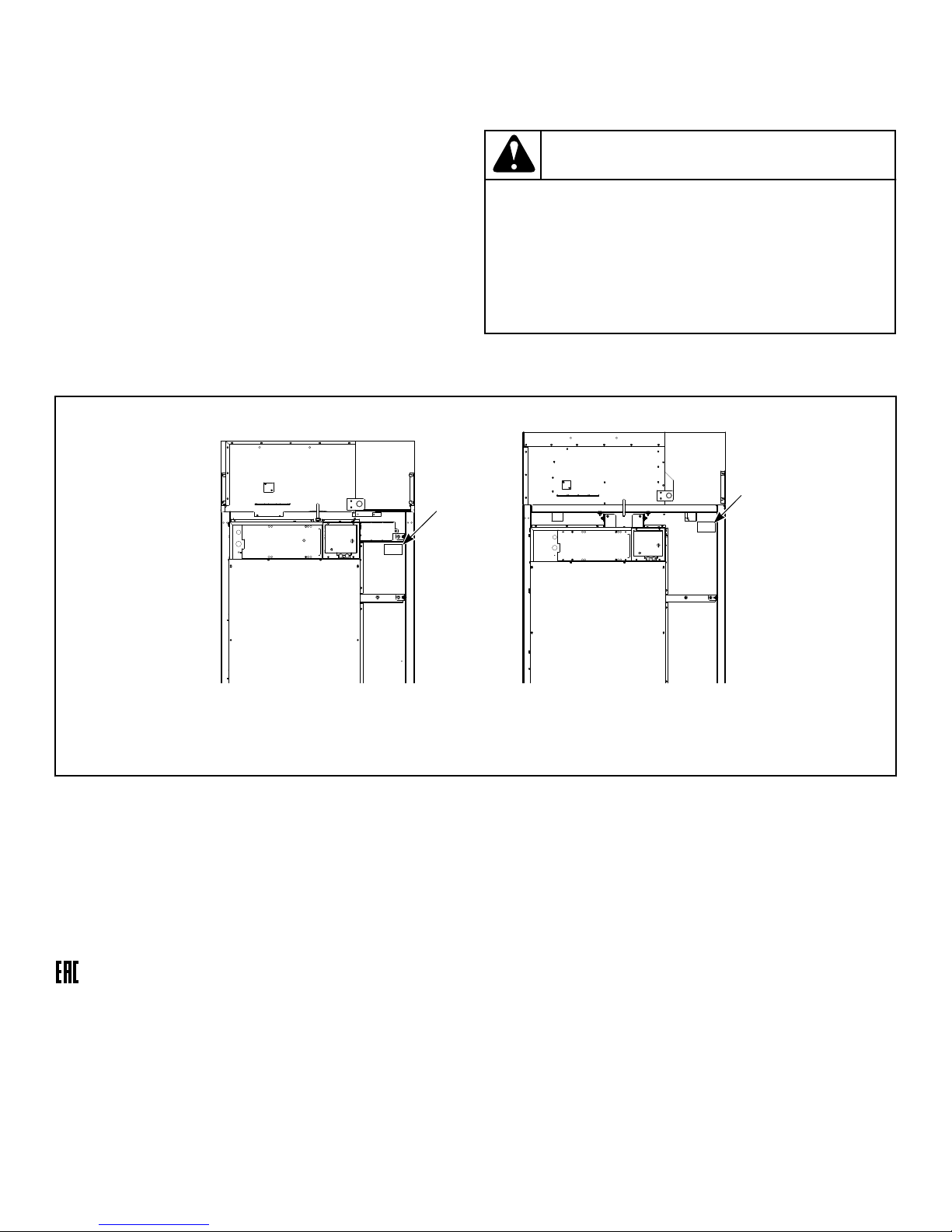
When calling or writing about your unit, PLEASE GIVE THE
MODEL AND SERIAL NUMBERS. The model and serial numbers are located on the serial plate. The serial plate will be in the
location shown in Figure 1 .
Date Purchased ______________________________
Model Number ______________________________
Serial Number _______________________________
Please include a copy of your bill of sale and any service receipts
you have.
WARNING
To reduce the risk of serious injury or death, DO NOT
repair or replace any part of the unit or attempt any
servicing unless specifically recommended in the
user-maintenance instructions or in published userrepair instructions that you understand and have the
skills to carry out.
W329
If replacement parts are required, contact the source from where
you purchased your unit.
NOTE: An alternate serial plate is located on the front of the machine on the inside of the loading door hinge.
1. Serial Plate
Figure 1
Manufacturing Date
The manufacturing date for your unit can be found on the serial
number. The first two digits indicate the year. The third and
fourth digits indicate the month. For example, a unit with serial
number 1505000001 was manufactured in May 2015.
©
Copyright, Alliance Laundry Systems LLC -
DO NOT COPY or TRANSMIT
12 Part No. 70532501ENR7
Page 13
Safety Information
Safety Information
Explanation of Safety Messages
Precautionary statements (“DANGER,” “WARNING,” and
“CAUTION”), followed by specific instructions, are found in this
manual and on machine decals. These precautions are intended
for the personal safety of the operator, user, servicer, and those
maintaining the machine.
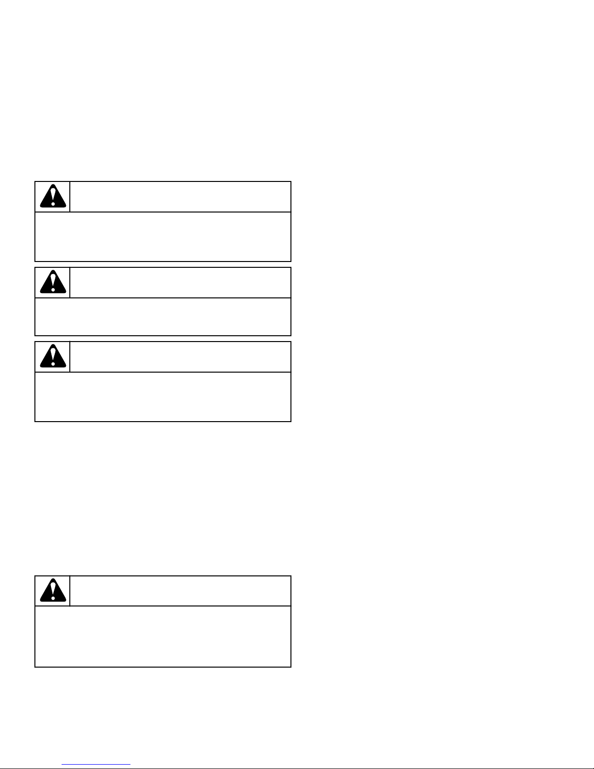
DANGER
Indicates an imminently hazardous situation that, if
not avoided, will cause severe personal injury or
death.
WARNING
Indicates a hazardous situation that, if not avoided,
could cause severe personal injury or death.
CAUTION
Indicates a hazardous situation that, if not avoided,
may cause minor or moderate personal injury or
property damage.
Additional precautionary statements (“IMPORTANT” and
“NOTE”) are followed by specific instructions.
IMPORTANT: The word “IMPORTANT” is used to inform the reader of specific procedures where minor
machine damage will occur if the procedure is not followed.
NOTE: The word “NOTE” is used to communicate installation, operation, maintenance or servicing information that is important but not hazard related.
Important Safety Instructions
WARNING
To reduce the risk of fire, electric shock, serious injury or death to persons when using your tumble
dryer, follow these basic precautions.
W776R1
Save These Instructions
• Read all instructions before using the tumble dryer.
• Install the tumble dryer according to the INSTALLATION instructions. Refer to the EARTHING (grounding) instructions
for the proper earthing (grounding) of the tumble dryer. All
connections for electrical power, earthing (grounding) and gas
supply must comply with local codes and be made by licensed
personnel when required. It is recommended that the machine
be installed by qualified technicians.
• Do not install or store the tumble dryer where it will be exposed to water and/or weather. The tumble dryer cannot be
used in a closed room where the air supply is insufficient. If
necessary, ventilation grids must be installed in the doors or
the windows.
• This tumble dryer must not be activated without lint screen
filter.
• When you perceive a gas odor, immediately shut off the gas
supply and ventilate the room. Do not power on electrical appliances and do not pull electrical switches. Do not use
matches or lighters. Do not use a phone in the building. Warn
the installer, and if so desired, the gas company, as soon as
possible.
• To avoid fire and explosion, keep surrounding areas free of
flammable and combustible products. Regularly clean the cylinder and exhaust tube should be cleaned periodically by
competent maintenance personnel. Daily remove debris from
lint screen filter and inside of filter compartment.
• Do not use or store flammable materials near this appliance.
• Do not place into tumble dryer articles that have been previously cleaned in, washed in, soaked in or spotted with gasoline or machine oils, vegetable or cooking oils, cleaning waxes or chemicals, dry-cleaning solvents, thinner or other flammable or explosive substances as they give off vapors that
could ignite, explode or cause fabric to catch on fire by itself.
• Do not spray aerosols in the vicinity of this appliance while it
is in operation.
• Items such as foam rubber (latex foam), shower caps, waterproof textiles, rubber backed articles and clothes or pillows
filled with foam rubber pads should not be dried in the tumble
dryer. Do not use the appliance to dry materials with a low
melting temperature (PVC, rubber, etc.).
• Do not tumble fiberglass curtains and draperies unless the label says it can be done. If they are dried, wipe out the cylinder
with a damp cloth to remove particles of fiberglass.
• Do not allow children to play on or in the dryer. Close supervision of children is necessary when the dryer is used near
children. This appliance is not intended for use by persons
(including children) with reduced physical, sensory or mental
capabilities, or lack of experience and knowledge, unless they
have been given supervision or instruction concerning the use
of the appliance by a person responsible for their safety. This
is a safety rule for all appliances.
• Cleaning and user maintenance shall not be made by children
without supervision.
©
Copyright, Alliance Laundry Systems LLC -
DO NOT COPY or TRANSMIT
13 Part No. 70532501ENR7
Page 14

Safety Information
• Children less than three years should be kept away unless
continuously supervised.
• Do not reach into the tumble dryer if the cylinder is revolving.
• Use tumble dryer only for its intended purpose, drying fabrics. Always follow the fabric care instructions supplied by
the textile manufacturer and only use the dryer to dry textiles
that have been washed in water. Only insert spin-dried linen
in the dryer to avoid damage to dryer.
• Always read and follow manufacturer’s instructions on packages of laundry and cleaning aids. Follow all warnings or precautions. To reduce the risk of poisoning or chemical burns,
keep them out of the reach of children at all times (preferably
in a locked cabinet).
• Do not use fabric softeners or products to eliminate static unless recommended by the manufacturer of the fabric softener
or product.
• Remove laundry immediately after tumble dryer stops.
• DO NOT operate the tumble dryer if it is smoking, grinding
or has missing or broken parts or removed guards or panels.
DO NOT tamper with the controls or bypass any safety devices.
• Tumble dryer will not operate with the loading door open. DO
NOT bypass the door safety switch to permit the tumble dryer
to operate with the door open. The tumble dryer will stop rotating when the door is opened. Do not use the tumble dryer if
it does not stop rotating when the door is opened or starts
tumbling without pressing the START mechanism. Remove
the tumble dryer from use and call for service.
• Tumble dryer will not operate with lint panel open. DO NOT
bypass lint panel door safety switch to permit the tumble dryer to operate with the lint panel door open.
• Do not alter this tumble dryer from factory construction except as otherwise described in the technical instructions.
• Always clean the lint filter daily. Keep area around the exhaust opening and adjacent surrounding area free from the accumulation of lint, dust and dirt. The interior of the tumble
dryer and the exhaust duct should be cleaned periodically by
qualified service personnel.
• Solvent vapors from dry-cleaning machines create acids when
drawn through the heater of the drying unit. These acids are
corrosive to the tumble dryer as well as the laundry load being
dried. Be sure make-up air is free of solvent vapors.
• At the end of each working day, close off all main supplies of
gas, steam and electricity.
IMPORTANT: For fire suppression equipped tumble
dryers, electricity and water should NOT be turned
off.
• Do not repair or replace any part of the tumble dryer, or attempt any servicing unless specifically recommended in the
user-maintenance instructions or in published user-repair instructions that the user understands and has the skills to carry
out. ALWAYS disconnect and lockout the electrical power to
the tumble dryer before servicing. Disconnect power by shutting off appropriate breaker or fuse.
• Activation of the emergency stop switch stops all tumble dryer control circuit functions, but DOES NOT remove all electrical power from tumble dryer.
• Exhaust ductwork should be examined and cleaned annually
after installation.
• Before the tumble dryer is removed from service or discarded,
remove the door to the drying compartment and the door to
the lint compartment.
• Failure to install, maintain, and/or operate this tumble dryer
according to the manufacturer’s instructions may result in
conditions which can produce bodily injury and/or property
damage.
NOTE: The WARNINGS and IMPORTANT SAFETY INSTRUCTIONS appearing in this manual are not meant
to cover all possible conditions and situations that may
occur. Observe and be aware of other labels and precautions that are located on the machine. They are intended to provide instruction for safe use of the machine. Common sense, caution and care must be exercised when installing, maintaining, or operating the
tumble dryer.
Always contact your dealer, distributor, service agent or the manufacturer about any problems or conditions you do not understand.
NOTE: All appliances are produced according the EMCdirective (Electro-Magnetic-Compatibility). They can be
used in restricted surroundings only (comply minimally
with class A requirements). For safety reasons there
must be kept the necessary precaution distances with
sensitive electrical or electronic device(s). These machines are not intended for domestic use by private
consumers in the home environment.
©
Copyright, Alliance Laundry Systems LLC -
DO NOT COPY or TRANSMIT
14 Part No. 70532501ENR7
Page 15

Specifications and Dimensions
Specifications and Dimensions
Specifications and Dimensions
Refer to machine serial plate for additional specifications.
Specifications 120 Series 170 Series 200 Series
Weights and Shipping Information
Net Weight (approximate):
Pounds [Kilograms ]
Standard Packaging Weight: Pounds
[Kilograms]
Slat Crate Packaging Weight: Pounds
[Kilograms]
Standard Packaging Shipping Dimensions: Inches [Millimeters ]
Standard Packaging Shipping Volume:
ft3 [m3]
Slat Crate Packagine Shipping Dimensions: Inches [Millimeters ]
Slat Crate Packaging Shipping Volume:
ft3 [m3]
Gas 1220 [555]
Steam 1330 [605]
Electric 1250 [565]
Gas 1290 [585]
Steam 1400 [635]
Electric 1320 [600]
Gas 1460 [660]
Steam 1570 [710]
Electric 1490 [675]
48.0 x 71.5 x 90.0 [1220 x
1820 x 2290]
179 [5.1] 220 [6.2] 243 [6.9]
53.0 x 74.5 x 90.9 [1350 x
1890 x 2310]
208 [5.9] 268 [7.6] 294 [8.3]
Gas 1400 [635]
Steam 1550 [705]
Gas 1480 [670]
Steam 1630 [740]
Gas 1670 [755]
Steam 1820 [825]
52.1 x 73.8 x 99.0 [1320 x
1870 x 2510]
60.1 x 76.8 x 100.3 [1530
x 1950 x 2550]
Gas 1550 [705]
Steam 1700 [770]
Gas 1630 [740]
Steam 1780 [805]
Gas 1820 [825]
Steam 1970 [895]
52.1 x 81.3 x 99.0 [1320 x
2070 x 2510]
60.1 x 84.3 x 100.3 [1530
x 2140 x 2550]
Cylinder Information
Cylinder Size: Inches [mm] 44.0 x 41.0 [1120 x 1040] 50.8 x 42.5 [1290 x 1080] 50.8 x 50.0 [1290 x 1270]
Cylinder Capacity dry weight: Pounds
[kg]
Cylinder Volume: ft3 [liter] 36.1 [1020] 49.8 [1410] 58.6 [1660]
Operational Information
Cylinder Motor: HP [kW] 1.5 [1.1] 1.5 [1.1] 1.5 [1.1]
Fan Motor: HP [kW] 1.5 [1.1] 1.5 [1.1] 1.5 [1.1]
Air Outlet Diameter: Inches [mm] 10.0 [254] 12.0 [305] 12.0 [305]
©
Copyright, Alliance Laundry Systems LLC -
DO NOT COPY or TRANSMIT
120 [55] 170 [77] 200 [90]
Table continues...
15 Part No. 70532501ENR7
Page 16

Specifications and Dimensions
Specifications 120 Series 170 Series 200 Series
Maximum Static Back Pressure: W.C.I.
0.80 [2.0, 0.20] 0.80 [2.0, 0.20] 0.80 [2.0, 0.20]
[mbar, kPa]
Minimum Static Back Pressure:
0.0 [0.0, 0.0] 0.0 [0.0, 0.0] 0.0 [0.0, 0.0]
W.C.I. [Millibar, kPa]
Maximum Airflow: C.F.M. [L/sec.] 1400 [660] 2150 [1,010] 2150 [1,010]
Heat dissipation of surface area exposed
60 [680,000] 60 [680,000] 60 [680,000]
to conditioned air: Btu/ft2 [Joules/m2]
Noise level measured during operation
60 dBA 69 dBA 69 dBA
at operator position of 3.3 feet [1 meter]
in front of machine and 5.2 feet [1.6 meters] from floor.
Door Opening Information
Door Opening Diameter: Inches [Milli-
27.0 [686] 27.0 [686] 27.0 [686]
meter]
Door Hinge Side Right Right Right
Door Maximum Open Angle: Degrees 180 180 180
Gas Models
Gas Connection 1 NPT 1 NPT 1 NPT
Gas Burner Rating:
270,000 [79, 290] 395,000 [116, 417] 425,000 [125, 448]
Btu/hr. [kW, Mj/hr.]
Steam Models
Steam Connection 3/4 NPT inlet
3/4 NPT outlet
Steam Coil Rating at 100 psig:
187,500 [88.8] 265,500 [125.7] 265,500 [125.7]
3/4 NPT inlet
1 NPT outlet
3/4 NPT inlet
1 NPT outlet
Btu/hr. [kg/hr.] (recommended operating
pressure 80-100 psig)
Electric Models
Heating Element Rating: Kilowatts
60 Not Applicable Not Applicable
(kW)
NOTE: All IEC machines are shipped with an adapter to
convert the gas connection threads to BSPT (from
NPT).
©
Copyright, Alliance Laundry Systems LLC -
DO NOT COPY or TRANSMIT
16 Part No. 70532501ENR7
Page 17
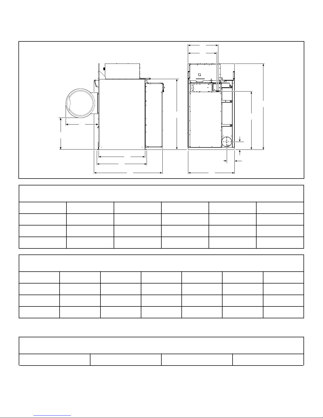
Cabinet Dimensions and Exhaust Outlet Locations
TMB2428N_SVG
Y
Z
H
C
D
E
F
K
G
J
I
B
A
Specifications and Dimensions
Cabinet Dimensions, in. [mm]
Models A B C D E
120 31.4 [800] 32.5 [825] 46.5 [1180] 49.9 [1270] 67.9 [1725]
170 33.9 [860] 32.5 [825] 48.3 [1125] 51.8 [1315] 69.8 [1775]
200 32.1 [815] 34.0 [865] 55.8 [1420] 59.3 [1505] 77.3 [1965]
Cabinet Dimensions, in. [mm]
Models F G H I* J* K*
120 46.1 [1170] 85.7 [2175] 70.0 [1780] 28.6 [725] 30.1 [765] 58.0 [1475]
170 52.9 [1345] 94.0 [2390] 75.0 [1905] 32.7 [830] 34.3 [870] 60.8 [1545]
200 52.9 [1345] 94.0 [2390] 75.0 [1905] 32.7 [830] 34.3 [870] 60.8 [1545]
* Fire suppression system optional - may not be on machine. Refer to Position and Level the Tumble Dryer to temporarily re-
duce the heights of these models.
Rear Exhaust Dimensions, in. [mm]
Models Diameter Y Z
©
Copyright, Alliance Laundry Systems LLC -
DO NOT COPY or TRANSMIT
Table continues...
17 Part No. 70532501ENR7
Page 18

Specifications and Dimensions
Rear Exhaust Dimensions, in. [mm]
120 10.0 [250] 7.6 [195] 7.6 [195]
170 12.0 [305] 8.8 [225] 11.0 [280]
200 12.0 [305] 8.8 [225] 11.0 [280]
©
Copyright, Alliance Laundry Systems LLC -
DO NOT COPY or TRANSMIT
18 Part No. 70532501ENR7
Page 19
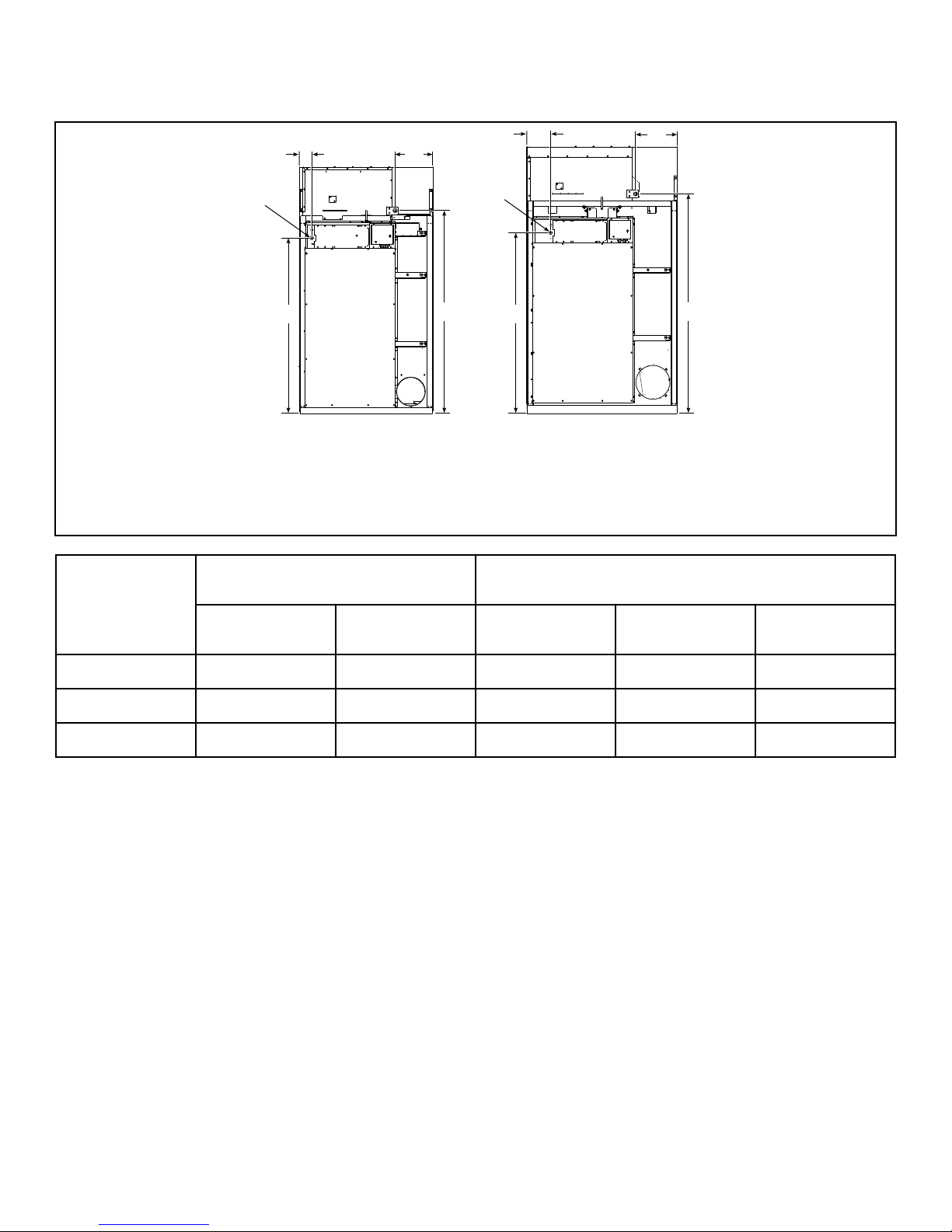
Electric and Gas Connection Locations for Gas Models
TMB2430N_SVG
D
B
C
A
D
B
C
A
21
3
3
1. 120
2. 170 and 200
3. Electrical Connection 1.125 in. [29 mm] Diameter
Specifications and Dimensions
Electrical Connection, in. [mm] Gas Connection, in. [mm]
Models
A B C D Diameter
120 3.9 [100] 60.9 [1545] 12.9 [330] 70.2 [1785] 1 NPT
170 8.0 [205] 63.7 [1620] 14.6 [370] 77.4 [1965] 1 NPT
200 8.0 [205] 63.7 [1620] 14.6 [370] 77.4 [1965] 1 NPT
©
Copyright, Alliance Laundry Systems LLC -
DO NOT COPY or TRANSMIT
19 Part No. 70532501ENR7
Page 20
TMB2577N_SVG
B2
B2
B1
B1
D
D
E
E
F
F
A2
A2
A1
A1
C
C
21
3
3
4
4
Specifications and Dimensions
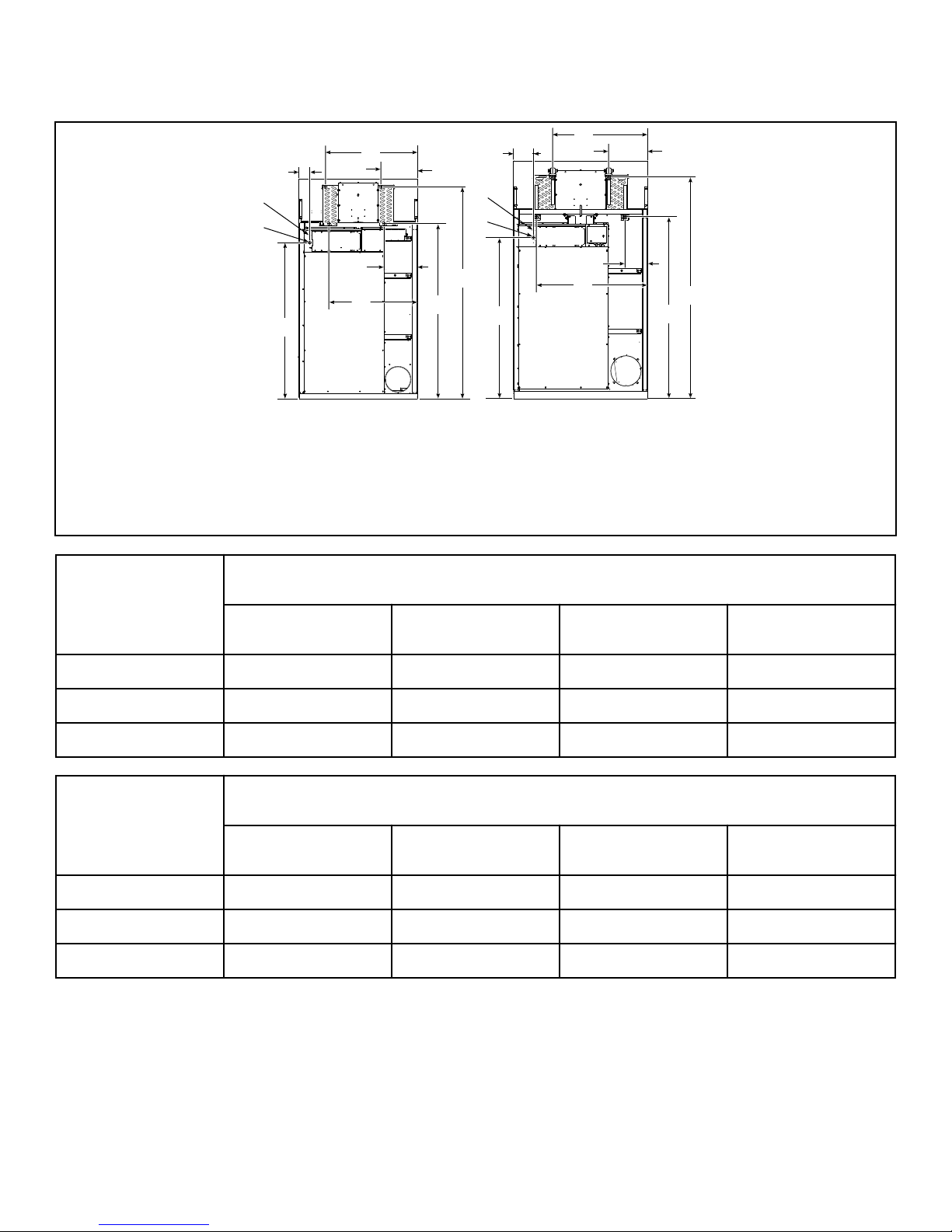
Electric and Steam Connection Locations for Steam Models
1. 120
2. 170 and 200
3. Electrical Connection 0.875 in. [22 mm] Diameter
4. Electrical Connection 1.125 in. [29 mm] Diameter
Steam Inlet, in. [mm]
Models
Diameter A1 A2 F
120 3/4 NPT 35.9 [910] 14.3 [365] 82.5 [2095]
170 3/4 NPT 37.6 [955] 15.5 [395] 87.6 [2225]
200 3/4 NPT 37.6 [955] 15.5 [395] 87.6 [2225]
Steam Outlet, in. [mm]
Models
Diameter B1 B2 D
120 3/4 NPT 34.6 [880] 13.1 [335] 68.5 [1740]
170 1 NPT 44.0 [1120] 9.0 [230] 72.0 [1830]
200 1 NPT 44.0 [1120] 9.0 [230] 72.0 [1830]
©
Copyright, Alliance Laundry Systems LLC -
DO NOT COPY or TRANSMIT
20 Part No. 70532501ENR7
Page 21

Electrical Connection, in. [mm]
Specifications and Dimensions
Models
C E
120 3.9 [100] 60.9 [1545]
170 8.0 [205] 63.7 [1620]
200 8.0 [205] 63.7 [1620]
©
Copyright, Alliance Laundry Systems LLC -
DO NOT COPY or TRANSMIT
21 Part No. 70532501ENR7
Page 22

TMB2578N_SVG
A
B
1
Specifications and Dimensions
Electric Connection Location for Electric Models
1. Electrical Connection 2.5 in. [64 mm] Diameter
Connection Dimensions, in. [mm]
Models A B
120 36.4 [925] 85.6 [2175]
©
Copyright, Alliance Laundry Systems LLC -
DO NOT COPY or TRANSMIT
22 Part No. 70532501ENR7
Page 23

Installation
Installation
Pre-Installation Inspection
Upon delivery, visually inspect the crate, carton and parts for any
visible shipping damage. If the crate, carton, or cover is damaged
or signs of possible damage are evident, have the carrier note the
condition on the shipping papers before the shipping receipt is
signed, or advise the carrier of the condition as soon as it is discovered.
Remove the crate and protective cover as soon as possible and
check the items listed on the packing list. Advise the carrier of
any damaged or missing articles as soon as possible. A written
claim should be filed with the carrier immediately if articles are
damaged or missing.
IMPORTANT: Remove the yellow shipping wire tie securing the airflow switch.
IMPORTANT: Warranty is void unless tumble dryer is
installed according to instructions in this manual. Installation should comply with minimum specifications
and requirements detailed in this manual and applicable local gas fitting regulations, municipal building codes, water supply regulations, electrical wiring regulations, and any other relevant statutory regulations. Due
to varied requirements, applicable local codes should
be thoroughly understood and all pre-installation work
arranged for accordingly.
Materials Required (Obtain Locally)
Materials Required (Obtain Locally)
Steam Models One steam shut-off valve for steam service
line to be connected upstream of solenoid
steam valve.
Two steam shut-off valves for each condensate return line.
Flexible steam hoses with a 125 psig
[pounds per square inch gauge] [862 kPa]
working pressure for connecting steam
coils. Refer to Figure 16 and Figure 17 for
sizing and connection configurations.
Two steam traps for steam coil outlets to
condensate return line.
Optional – Two vacuum breakers for condensate return lines.
IMPORTANT: 3 Phase Only – Each tumble dryer must
be connected to its own individual branch circuit
breaker, not fuses, to avoid the possibility of “single
phasing” and causing premature failure of the motor(s).
Location Requirements
The tumble dryer must be installed on a level floor. Floor covering materials such as carpeting or tile should be removed.
All Models Circuit breaker on 3 Phase models.
Table continues...
To assure compliance, consult local building code requirements.
The tumble dryer must not be installed or stored in area where it
will be exposed to water and/or weather.
IMPORTANT: DO NOT block the airflow at the rear of
the tumble dryer with laundry or other articles. Doing
so would prevent adequate air supply to the combustion chamber of the tumble dryer.
A typical tumble dryer enclosure is shown in Figure 2 .
IMPORTANT: Install tumble dryers with sufficient clearance for servicing and operation, refer to Figure 2 .
IMPORTANT: The dryer must not be installed behind a
lockable door, a sliding door or a door with a hinge on
the opposite side to that of the tumble dryer, in such a
way that a full opening of the tumble dryer door is restricted.
©
Copyright, Alliance Laundry Systems LLC -
DO NOT COPY or TRANSMIT
23 Part No. 70532501ENR7
Page 24

TMB2501N_SVG
4
3
1
5
6
7
8
2
Installation
WARNING
To reduce the risk of severe injury, clearance of tumble dryer cabinet from combustible construction
must conform to the minimum clearances, and/or local codes and ordinances.
W770R1
NOTE: Shaded areas indicate adjacent structure.
1. 0.0 in. [0 mm] minimum, 0.5 in. [13 mm] recommended between machines for removal or installation
2. Allow 2-4 in. [51-100 mm] opening at top of machine to aid in removal or installation. A removable trim piece may be used to
conceal the opening; zero clearance allowed for trim.
3. 4 in. [100 mm] maximum header thickness
4. Minimum clearance permitted for remainder:
120 Gas/Electric 4.0 in. [100 mm]
120 Steam 12.0 in. [300 mm]
170/200 Gas 4.0 in. [100 mm]
170/200 Steam 12.0 in. [300 mm]
5. Guard
6. Provision for make-up air
7. 24 in. [610 mm] minimum, 36 in. [910 mm] recommended for maintenance purposes
8. 0.0 in. [0 mm] minimum, 0.25 in. [6 mm] recommended for removal or installation purposes
Remove Shipping Materials
Figure 2
The foam wedge insert for the cylinder should be saved and
MUST be reinstalled whenever the unit is moved. To remove the
IMPORTANT: Remove the yellow shipping wire tie securing the airflow switch.
foam wedge insert, open the loading door and turn the cylinder
clockwise by using the lifter. The insert will drop into the lint
©
Copyright, Alliance Laundry Systems LLC -
DO NOT COPY or TRANSMIT
24 Part No. 70532501ENR7
Page 25

Installation
compartment. In the event the insert is not removed, it will be
dislodged once the tumble dryer starts.
For international models, remove bracket from drive motor and
install belt. Remove rear guard by unscrewing the six screws using a 5/16 inch wrench. After the screws are removed, lift the
panel off the positioning lugs located on the lower guard surface.
Before removing the shipping bracket, install the belt over the
drive motor pulley and the larger idler pulley. Center belt on pulleys. Remove the nuts from both ends holding the bracket in
place and remove the shipping bracket from the tumble dryer.
The belt will be tightened to the appropriate tension when the
bracket is removed. Keep bracket in case machine ever needs to
be relocated. Re-install rear guard
Position and Level the Tumble Dryer
The tumble dryer may be moved with or without the skid. To remove the skid, unscrew the four shipping bolts, and discard them.
To fit a 170 and 200 tumble dryer (with shipping skid) through a
8.0 foot [2.4 meters] high door, you must remove the front access
panel. The upper 3.0 inches [76 mm] of the gas heater must also
be removed on 170 gas tumble dryers. Removing the entire gas or
steam heater assembly and the shipping skid, will reduce the
height of the 120 tumble dryer to 70 inches [1,780 mm], and the
170 and 200 tumble dryer to 75 inches [1,910 mm].
Level the tumble dryer to within 0.13 inch [3.3 mm] from frontto-rear (level on cylinder rib), and side-to-side (level on upper access panel top surface). Shim under corners to level and stabilize
unit. Tumble dryer must not rock.
Mounting
Where local code requires the unit to be securely mounted, use
the shipping bolt frame holes found on the tumble dryer frame.
Use either epoxy 3/8 in. [10 mm] bolts or equivalent 3/8 in. [10
mm] concrete anchors, such as expandable bolts.
Fire Suppression System (Optional
Equipment)
Check Local Codes and Permits
Call your local water company or the proper municipal authority
for information regarding local codes.
IMPORTANT: It is your responsibility to have ALL
plumbing connections made by a qualified professional to assure that the plumbing is adequate and conforms to local, state, and federal regulations or codes.
IMPORTANT: It is the installation or owner’s responsibility to confirm that the necessary or required water,
water pressure, pipe size, or connections are provided.
Manufacturer assumes no responsibility if the fire suppression system is not connected, installed, or maintained properly.
Water Requirements
IMPORTANT: Water must be supplied to the fire suppression system, or the fire suppression system will
not operate as intended.
To ensure the fire suppression system operates properly:
• Water supply requirements: 3/4 inch hose connections providing 15 gpm [57 lpm] minimum flow; Water pressure 20 psi
[138 kPa] minimum, 120 psi [827 kPa] maximum; water temperature 40°F [4.5°C] minimum, 120°F [49°C] maximum
must be maintained at all times.
• Electric power to the tumble dryer must be provided at all
times.
• Perform preventative maintenance checks every month. Refer
to Operation/Maintenance Manual.
NOTE: Water pressure under 20 psi [138 kPa] will
cause low flow at water solenoid valve.
If the rear of the tumble dryer or the water supply is located in an
area where it will be exposed to cold/freezing temperatures, provisions must be made to protect these water lines from freezing.
IMPORTANT: Temperature of the water supply must be
kept between 40°F and 120°F [4.5°C and 49°C]. If water
in the supply line or water solenoid valve freezes, the
fire suppression system will not operate.
WARNING
ELECTRICAL SHOCK HAZARD. Electrical shock can
result in death or serious injury. If the water dispensing system is activated, do not attempt to operate
the tumble dryer. If the water dispensing system is
activated, have the tumble dryer inspected by a
qualified agency before operating the tumble dryer.
IMPORTANT: Main supplies of electricity and water to
the tumble dryer should remain on at all times for the
fire suppression system to work.
©
Copyright, Alliance Laundry Systems LLC -
DO NOT COPY or TRANSMIT
W879R1
IMPORTANT: If temperature sensors inside the tumble
dryer register a temperature below 40F° [4.5°C], the fire
suppression system control will lock out. This feature
protects against operation of the tumble dryer with a
possible frozen water supply. Only when the temperature sensors register a temperature 40F° [4.5°C] or
above will the machine reset for operation.
For installations where the tumble dryer must operate below 40°F
[4.5°C], a cold weather fire suppression system relocation kit
(part no. 44340301) is available. Refer to the instructions provided in the kit for proper installation.
25 Part No. 70532501ENR7
Page 26

TMB2433N_SVG
2
1
170/200
120
Installation
IMPORTANT: Flexible supply line/coupling must be
used. Solenoid valve failure due to hard plumbing connections will void the warranty. It is recommended that
a filter or strainer be installed in the water supply line.
Water Connections
WARNING
Electrical shock hazard. Can cause death or serious
injury. If the water dispensing system is activated do
not attempt to operate the dryer. If the water dispensing system is activated have the dryer inspected by a
qualified agency before operating the dryer.
• CALL THE FIRE DEPARTMENT.
• DO NOT disconnect electric power to the dryer.
• DO NOT disconnect water to the dryer.
• DO NOT touch the dryer.
W932
Connect tumble dryer to a backflow preventer (vacuum breaker)
before connecting to the public water main in all countries where
local regulations require specific water approval certificates.
Two hoses and a Y-connector are provided with the tumble dryer
to allow for connection of water supply to tumble dryer. DO NOT
reuse old hose sets.The water connections are made to the water
solenoid valve, located on the rear of the tumble dryer. The Yconnector provides a single female hose connection (Standard US
3/4-11 1/2 NH thread). Refer to Figure 3 and Figure 4 .
1. Fire Suppression System Control Box
2. Water Solenoid Valve
To connect the two hoses (supplied with tumble dryer), insert
rubber washers (from literature pack) in water inlet hose couplings. Refer to Figure 4 .
©
Copyright, Alliance Laundry Systems LLC -
DO NOT COPY or TRANSMIT
Figure 3
26 Part No. 70532501ENR7
Page 27

TMB2463N_SVG
3
2
4
2
1
1. Lock
2. Hose Couplings
3. Y-Connector
4. Inlet Hoses
Figure 4
Connect inlet hoses to water supply. Flush the lines for approximately two minutes to remove any foreign materials that could
clog the screens in the water mixing valve. This is especially important when installing a tumble dryer in a newly constructed or
renovated building. Then connect the hoses to the Y-connector;
connect the Y-connector to the connections at the rear of the tumble dryer.
IMPORTANT: Thread hose couplings onto valve connections finger tight, then turn 1/4 turn with pliers. Do
not cross thread or overtighten couplings.
IMPORTANT: Hoses and other natural rubber parts deteriorate after extended use. Hoses may develop
cracks, blisters or material wear from the temperature
and constant high pressure they are subjected to. All
hoses should be checked on a yearly basis for any visible signs of deterioration. Any hose showing the signs
of deterioration listed above should be replaced immediately. All hoses should be replaced every five years.
Installation
Electrical Requirements
WARNING
Electrical power must be provided to tumble dryer at
all times. The fire suppression system will be inoperative if the main electrical power supply is disconnected.
W690R1
No independent external power source or supply connection is
necessary. Power to operate the fire suppression system is from
the tumble dryer main power supply.
Auxiliary Alarm
The fire suppression system provides an auxiliary output contact
when the system is activated. During tumble dryer installation,
you have the option to connect a separate alarm system to this
auxiliary output. Potential uses of the auxiliary output include,
but are not limited to: (1) sounds an alarm, (2) activates a building sprinkler system, (3) notifies a fire department, etc. Use of the
auxiliary output is not required for the fire suppression system to
operate, but may be used for additional protection.
The connection to the auxiliary output is made through the H-4
header connection inside the fire suppression control box. Refer
to Figure 5 . The relay is rated for 5 Amp, 250VAC max.
NOTE: The auxiliary output is activated during fire suppression system maintenance test sequence. Consider
this fact prior to your system test every month. (Example: If the external system uses the auxiliary output to
call the fire department, inform the fire department before and after the fire suppression system maintenance
test. If the external system uses the auxiliary output to
activate a building sprinkler, disconnect auxiliary output prior to test.)
NOTE: Longer inlet hoses are available (as optional
equipment at extra cost) if the hoses supplied with the
tumble dryer are not long enough for installation. Order
hoses as follows:
Part No. 20617 Inlet hose 8.0 feet [2.4 m]
Part No. 20618 Inlet hose 10 feet [3.0 m]
©
Copyright, Alliance Laundry Systems LLC -
DO NOT COPY or TRANSMIT
27 Part No. 70532501ENR7
Page 28

TMB2452N_SVG1
4 3 2
1
Installation
1. Auxiliary Alarm Fast-On Connection (there is a plastic
shield over the control board that must be tipped down to
access this connection)
2. Test Button
3. Light
4. Reset Button
Figure 5
Before Placing Tumble Dryer into
Service
1. Ensure all panels and guards are in place.
2. Remove and discard wire tie from the airflow switch so it can
swing freely.
3. Pull out emergency stop button, if applicable.
4. Turn on electrical supply to tumble dryer.
5. Open the supply valve for gas or steam heated tumble dryers.
6. After performing the previous checks, start the tumble dryer
by pressing START. (Refer to the Operating section for detailed instructions.) Release the start button and open the
loading door. The cylinder should stop rotating within seven
seconds after the door is opened a maximum of 0.79 inches
[20 mm]. If it does not, adjust the loading door switch. Refer
to Adjustments section.
7. Gas Tumble Dryers: Start the tumble dryer and check the
burner flame. Adjust the air inlet shutter as required. Refer to
Adjustments section.
IMPORTANT: The electronic ignition system will attempt to light the gas by sparking for the “trial for
ignition” period. If gas does not ignite within this
period, the ignition control will go into a safety lockout and the valve will no longer open until the control is reset. On CSA models, the electronic ignition
system is automatically reset. On AGA and IEC
models the electronic ignition system must be manually reset. The control will pause the cycle and indicate that the ignition control needs to be reset. To
reset the ignition control, press start key on the
control. The control will then prompt for the start
key to be pressed again to restart the cycle. On all
models, ignition lockout may occur due to air in the
gas line or the gas shut-off valve being in the OFF
position. If the air is bled out of the gas line, the gas
shut-off valve is in the ON position, the gas service
is properly connected and the tumble dryer continues to have heater errors and/or prompts for the ignition control to be reset, remove the tumble dryer
from service.
8. Load the cylinder with a full load of clean rags and run to remove oil or dirt from cylinder.
9. Check the airflow switch operation by opening the lint panel;
be sure to remove shipping wire tie from airflow switch prior
to operation. Temporarily tape down the lint panel safety
switch located behind the upper left corner of the lint panel.
The heating systems should shut off when the lint panel is
opened a maximum of 6.0 inches [152 mm] .
The airflow switch operation may be affected by shipping wire
tie still in place, lack of make-up air, or an obstruction in the exhaust duct. These should be checked. If there is a problem, contact an authorized service person.
IMPORTANT: Remove tape from the lint panel safety
switch before proceeding to the next step.
WARNING
Do not operate tumble dryer if airflow switch is
faulty. An explosive gas mixture could collect in
tumble dryer if airflow switch does not operate
properly.
W407R1
10. Clean cylinder by running a load of wet rags on one maximum heat cycle.
©
Copyright, Alliance Laundry Systems LLC -
DO NOT COPY or TRANSMIT
28 Part No. 70532501ENR7
Page 29

Installation
Models
Prepurge Time
(seconds)
Interpurge Time
(seconds)
CSA 1 23 10
Trial for Ignition
(seconds)
Reset Lockout
Condition By:
Automatically resets.
(attempts to ignite 3
times)
AGA and IEC 23 23 10 Press start key with ac-
cess panel open.
If the tumble dryer does not meet ANY of the listed requirements, remove tumble dryer from use. Refer to Removing Tumble Dryer
from Service section.
Required for IEC Models Only
Once tumble dryer is installed, please be sure to complete the following items:
• Review and verify machine operation with customer.
• Leave all literature and a signed Declaration of Conformity
with customer.
• Review tumble dryer warranty information with customer.
• Apply cautionary stickers in language appropriate to country
of sale. Market language label kits have been provided in the
literature packet located in the cylinder. Position appropriate
market language labels on the tumble dryer in the following
regions prior to placing tumble dryer into service, if applicable:
• On front panel at the periphery of cylinder access opening
• On electrical box cover(s) (electric heat models have two
electrical box covers)
• On rear panel
• On front panel near emergency stop button (fire suppres-
sion system equipped models only)
• On fire suppression control box (fire suppression system
equipped models only)
©
Copyright, Alliance Laundry Systems LLC -
DO NOT COPY or TRANSMIT
29 Part No. 70532501ENR7
Page 30

Exhaust Requirements
Exhaust Requirements
Exhaust Requirements
CAUTION
Risk of fire. A clothes dryer produces combustible
lint. Exhaust outdoors. Consult technical instructions for detailed exhaust specifications.
WARNING
To reduce the risk of fire, DO NOT use plastic or thin
foil ducting to exhaust the tumble dryer.
WARNING
To reduce the risk of fire and accumulation of combustible gases, DO NOT exhaust tumble dryer air into a window well, gas vent, chimney or enclosed, unventilated area such as an attic wall, ceiling, crawl
space under a building, or concealed space of a
building.
Layout
W933
W773R1
W059R1
Make-Up Air
A tumble dryer is forced air exhausted and requires provisions for
make-up air to replace air exhausted by tumble dryer.
IMPORTANT: Do not obstruct flow of combustion and
ventilation air.
Required Make-Up Air Opening (to the outside) for
Each Tumble Dryer, in.2 [cm2]
Model Opening
120 Series 360 [2300]
170 Series 525 [3400]
200 Series 525 [3400]
Make-up air openings with louvers will restrict airflow. The
opening must be increased to compensate for area taken up and
restrictions created by louvers. Contact the louver manufacturer
for the exact specifications.
Make-up air openings in rooms containing tumble dryer(s) and/or
gas fired hot water heater or other gravity vented appliances must
be increased sufficiently to prevent downdrafts in any of the
vents when all tumble dryers are in operation. Do not locate gravity vented appliances between tumble dryer(s) and make-up air
openings. If it is necessary to duct make-up air to tumble dryer(s), increase area of duct work by 25% to compensate for restrictions in air movement.
Whenever possible, install tumble dryers along an outside wall
where duct length can be kept to a minimum, and make-up air
can be easily accessed. Construction must not block the airflow at
the rear of the tumble dryer. Doing so would prevent adequate air
supply to the tumble dryer combustion chamber.
©
Copyright, Alliance Laundry Systems LLC -
DO NOT COPY or TRANSMIT
Venting
WARNING
To reduce the risk of fire due to increased static
pressure, we do not recommend installation of inline secondary lint filters or lint collectors. If secondary systems are mandated, frequently clean the
system to assure safe operation.
W749
IMPORTANT: Installing in-line filters or lint collectors
will cause increased static pressure. Failure to maintain the secondary lint system will decrease tumble
dryer efficiency and may void machine warranty.
For maximum efficiency and minimum lint accumulation, tumble
dryer air must be exhausted to the outdoors by the shortest possible route.
30 Part No. 70532501ENR7
Page 31

TMB2562N_SVG
1
2
Exhaust Requirements
Proper sized exhaust ducts are essential for proper operation. All
elbows should be sweep type. Exhaust ducts must be assembled
so the interior surfaces are smooth, so the joints do not permit the
accumulation of lint. DO NOT use plastic, thin foil or Type B
flexible ducts - rigid metal ducts are recommended. Use exhaust
ducts made of sheet metal or other noncombustible material. DO
NOT use sheet metal screws or fasteners on exhaust pipe joints
which extend into the duct and catch lint. Use of duct tape or
pop-rivets on all seams and joints is recommended, if allowed by
local codes.
Verify that old ducts are thoroughly cleaned out before installing
new tumble dryer(s).
WARNING
Improperly sized or assembled ductwork causes excess back pressure which results in slow drying, lint
collecting in the duct, lint blowing back into the
room, and increased fire hazard.
W355
NOTE: Exhaust ducts must be constructed of sheet
metal or other noncombustible material. Such ducts
must be equivalent in strength and corrosion resistance to ducts made of galvanized sheet steel not less
than 0.02 inches [0.50 mm] thick.
NOTE: Proper venting will ensure that any condensate
is subsequently re-evaporated and discharged.
NOTE: On IEC approved tumble dryers where it may
be required, an exhaust adapter is available to convert to female outlet. Contact local distributor or
manufacturer.
Where the exhaust duct pierces a combustible wall or ceiling, the
opening must be sized per local codes. The space around the duct
may be sealed with noncombustible material. Refer to Figure 7 .
IMPORTANT: For best performance provide an individual exhaust duct for each tumble dryer. Do not install a
gas water heater in a room containing tumble dryers. It
is better to have the water heater in a separate room
with a separate air inlet.
1. Not Applicable
2. 120, 170, 200 Models
Figure 6
©
Copyright, Alliance Laundry Systems LLC -
DO NOT COPY or TRANSMIT
31 Part No. 70532501ENR7
Page 32

TMB2361N_SVG
5
4
3
2
1
TMB2362N_SVG
5
4
3
2
1
TMB2426N_SVG
5
4
3
2
1
Exhaust Requirements
1. Removable strip of panel in framing wall to permit removal of tumble dryer from framing wall
2. Partition or bulkhead
3. Minimum distance between exhaust opening and roof, ground or other obstruction, 36 in. [910 mm]
4. 2.0 in. [50 mm] minimum clearance on both sides of duct
5. Exhaust airflow – maximum length of rigid duct 14 ft. [4.3 m] or 7.9 ft. [2.4 m] of flexible metal duct
Figure 7
NOTE: Do not install wire mesh or screen in exhaust
duct opening to avoid lint build-up or impacting proper
discharge of air from tumble dryers.
NOTE: Where exhaust duct pierces a combustible wall
or ceiling, the opening must be sized per local codes.
NOTE: Inside of duct must be smooth. Do not use
sheet metal screws to join sections.
NOTE: Locate exhaust far enough away from make-up
NOTE: Static back pressure must be measured with the
tumble dryer running.
The maximum allowable length venting is 14 feet [4.3 m] and
two 90° elbows or equivalent. If the equivalent length of a duct
required for an installation exceeds the maximum allowable
equivalent length, the diameter of a round duct must be increased
by 10% for each additional 20 feet [6.1 m]. Cross section area of
a rectangular duct must be increased by 20% for each additional
20 feet [6.1 m]. Refer to Table 1 to determine equivalent venting.
air location to prevent re-introduction.
Consult your local building code for regulations which may also
apply.
Individual Venting
For maximum efficiency and performance, it is preferred to exhaust tumble dryer(s) individually to the outdoors.
IMPORTANT: At no point may the cross sectional area
Duct Diameter
10 in. [254 mm] One 90° elbow = 11.6 ft. [3.5
12 in. [305 mm] One 90° elbow = 14 ft. [4.3
Equivalent Length of
Rigid Straight Duct
m]
m]
of installed venting be less than the cross sectional
area of the exhaust outlet of the tumble dryer.
The exhaust duct must be designed so the static back pressure
measured 12 inches [305 mm] from the exhaust outlet does not
exceed the maximum allowable pressure specified in the Specifications and Dimensions Table or on the installation sticker on the
rear of the tumble dryer.
14 in. [356 mm] One 90° elbow = 16 ft. [4.9
m]
16 in. [406 mm] One 90° elbow = 18.7 ft. [5.7
m]
Table 1 continues...
©
Copyright, Alliance Laundry Systems LLC -
DO NOT COPY or TRANSMIT
32 Part No. 70532501ENR7
Page 33

T438i_SVG
Exhaust Requirements
Equivalent Length of
Duct Diameter
Rigid Straight Duct
18 in. [457 mm] One 90° elbow = 21 ft. [6.4
m]
Equivalent Length (meter) = 1.17 x Duct Diameter (mm)
Table 1
Example: A 12 inch [305 mm] diameter duct’s equivalent length
of 14 feet [4.3 m] of duct and two 90° elbows is:
Equivalent Length
= 14 ft. [4.3 m] + (2) 90° elbows
= 14 ft. [4.3 m] + 14 ft. [4.3 m] + 14 ft. [4.3 m]
= 42 ft. [12.8 m]
With the tumble dryer in operation, airflow at any point in the
duct should be at least 1200 feet/min. [366 m/min.] to ensure that
lint remains airborne. If 1200 feet/min. [366 m/min.] cannot be
maintained, schedule monthly inspections and cleaning of the
ductwork.
NOTE: The maximum length of a flexible metal duct
must not exceed 7.9 ft. [2.4 m] as required to meet
UL2158, clause 7.3.2A.
round duct must be increased by 10% for each additional 20 feet
[6.1 m]. Cross sectional area of a rectangular or square duct must
be increased 20% for each additional 20 feet [6.1 m]. Refer to
Table 2 to determine equivalent ducting sizing. The collector duct
may be rectangular or square in cross section, as long as the area
is not reduced. Provisions MUST be made for lint removal and
cleaning of the collector duct.
The vent collector system must be designed so the static back
pressure measured 12 inches [305 mm] from the exhaust outlet
does not exceed the maximum allowable pressure specified in the
Specifications and Dimensions Table or on the installation sticker
on the rear of tumble dryer. Static back pressure must be measured with all tumble dryers vented into the collector operating.
NOTE: Never connect a tumble dryer duct at a 90° angle to the collector duct. Refer to Figure 8 . Doing so
will cause excessive back pressure, resulting in poor
performance. Never connect two tumble dryer exhaust
ducts directly across from each other at the point of
entry to the collector duct.
With the tumble dryer in operation, airflow at any point in the
duct should be at least 1200 feet/min. [366 m/min.] to ensure that
lint remains airborne. If 1200 feet/min. [366 m/min.] cannot be
maintained, schedule monthly inspections and cleaning of the
ductwork.
Manifold Venting
While it is preferable to exhaust tumble dryers individually to the
outdoors, a main collector duct may be used if it is sized according to Figure 9 and Figure 10 . This illustration indicates mini-
mum diameters, and should be increased if the collector length
exceeds 14 feet [4.3 m] and two 90° elbows. The diameter of a
Figure 8
©
Copyright, Alliance Laundry Systems LLC -
DO NOT COPY or TRANSMIT
33 Part No. 70532501ENR7
Page 34

TMB2403N_SVG
L
K
J
I
H
G
F
E
D
C
B
A
1
2
Exhaust Requirements
One Manifold Assembly
1. Outlet duct diameter = largest duct diameter based on number of tumble dryers
2. 45° typical
Figure 9
Duct Station 120 Series 170/200 Series
A 10 in. [254 mm] 12 in. [305 mm]
B 15 in. [381 mm] 17 in. [432 mm]
C 18 in. [457 mm] 21 in. [533 mm]
D 21 in. [533 mm] 24 in. [610 mm]
E 24 in. [610 mm] 27 in. [686 mm]
F 26 in. [660 mm] 30 in. [762 mm]
G 28 in. [711 mm] 32 in. [813 mm]
H 30 in. [762 mm] 34 in. [864 mm]
I 32 in. [813 mm] 36 in. [914 mm]
J 33 in. [838 mm] 38 in. [965 mm]
K 35 in. [889 mm] 40 in. [1,016 mm]
L 36 in. [914 mm] 42 in. [1,067 mm]
NOTE: Table 2 represents tumble dryers with the same
vent size. If multiple vent sizes are used, consult a local HVAC specialist.
©
Copyright, Alliance Laundry Systems LLC -
DO NOT COPY or TRANSMIT
Table 2
NOTE: Duct clean-out recommended every 6 feet [0.18
m].
34 Part No. 70532501ENR7
Page 35

Two Manifold Assemblies
TMB2018N_SVG
1
2
L L
K K
J J
I
AA
I
Exhaust Requirements
1. Outlet duct diameter = combined largest duct diameter of both sides
2. 45° typical
Figure 10
Refer to Table 2 for measurements for each manifold.
©
Copyright, Alliance Laundry Systems LLC -
DO NOT COPY or TRANSMIT
35 Part No. 70532501ENR7
Page 36

Gas Requirements
Gas Requirements
Gas Requirements
CAUTION
• Thoroughly test all piping for leaks before operating. All fittings and piping must be tight and supported against breakage and vibration.
• Turn off primary gas line shut off cock when not
in use (overnight, weekends, holidays, etc.).
W934
WARNING
To reduce the risk of fire or explosion, DO NOT CONNECT THE GAS LINE TO THE TUMBLE DRYER IF
THE GAS SERVICE IS NOT THE SAME AS THAT
SPECIFIED ON THE TUMBLE DRYER SERIAL PLATE!
It will first be necessary to convert the gas burner orifice and gas valve. Appropriate conversion kits are
available.
W060R1
WARNING
To reduce the risk of gas leaks, fire or explosion, use
a new flexible stainless steel connector.
W774
IMPORTANT: Any product revisions or conversions
must be made by the Manufacturer’s Authorized Dealers, Distributors or local service personnel.
IMPORTANT: The tumble dryer must be isolated from
the gas supply piping system by closing its individual
manual shut-off valve during any pressure testing of
the gas supply piping system. Gas supply pressure
must never exceed 1/2 PSI [3.5 mbar] during leak testing. Gas supply must provide 6.5+/-1.5 inches
[16.32+/-3.7 mbar] with all gas appliances firing.
NOTE: For gas valves with a manual shut-off switch on
the gas valve, the shut-off switch does not protect the
valve from this pressure test. Use the individual manual shut-off valve from the gas supply piping system to
protect the gas valve.
IMPORTANT: The installation must comply with local
codes or, in the absence of local codes:
• with the latest edition of the “National Fuel Gas
Code,” ANSI Z223.1/NFPA 54 in the U.S.A.
• with CAN/CSA-B149.1 Natural Gas and Propane Installation Code in Canada
• In Australia and New Zealand , installation must
comply with the Gas Installations Standard AS/NZS
5601 Part 1: General Installations.
• In the EU, installation must comply with the installation regulations of the country of destination.
IMPORTANT: For Australian models, do not remove the
gas type label on the rear of the unit.
Obtain specific gas service pipe size from the gas supplier. Refer
to Table 4 and Table 5 for general pipe size.
The following must be furnished and installed by the customer
for the gas service line to each tumble dryer. Refer to Figure 11 .
• Sediment traps
• Shut-off valves (supplied in literature bag)
• Supply pressure taps (1/8 NPT minimum) (refer to Figure 11 )
• Union at gas supply connection (listed to ANSI Z21.24 and
CSA 6.10)
It is important that equal pressure be maintained at all tumble
dryer gas connections. This can be done by installing a 1 inch
pipe gas loop to maintain equal pressure at all gas connections.
Refer to Figure 15 .
WARNING
To reduce the risk of fire or explosion, if the tumble
dryer is to be connected to Liquefied Petroleum
(L.P.) gas, a vent to the outdoors must be provided in
the room where the tumble dryer is installed.
W062R1
Before installation, check that the local distribution conditions,
nature of gas and pressure, and the adjustment of the appliance
are compatible.
NATURAL GAS supply pressures with all gas appliances running (tumble dryers, water heaters, space heaters, furnace, etc.):
©
Copyright, Alliance Laundry Systems LLC -
DO NOT COPY or TRANSMIT
36 Part No. 70532501ENR7
Page 37

Gas Requirements
CSA Models
AGA Models
CE Models
Maximum 10.5 in. w.c. 2.61 kPa Refer to Table
Recommend-ed6.5 in. w.c 1.62 kPa
3
Minimum 5 in. w.c. 1.13 kPa
An in-line pressure regulator may be required if the line pressure
exceeds 10.5 water column inches [26.1 mbar, 2.61 kPa] with all
gas appliances running.
PROPANE/LIQUID PETROLEUM GAS (L.P.G.) supply pressures with all gas appliances running (tumble dryers, water heaters, space heaters, furnace, etc.):
CSA Models
AGA Models
CE Models
Maximum 13 in. w.c. 3.23 kPa Refer to Table
Recommend-ed11 in. w.c. 2.74 kPa
3
Minimum 10 in. w.c. 2.49 kPa
©
Copyright, Alliance Laundry Systems LLC -
DO NOT COPY or TRANSMIT
37 Part No. 70532501ENR7
Page 38

Gas Requirements
Supply Pressure (mbar)
Gas Category
II
2H3B/P
II
2H3B/P
II
2H3B/P
II
2H3+
II
2E3B/P
II
2E3B/P
Country
BG, CY, CZ,
DK, EE, FI,
HR, LT, NO,
Gas
G20 2H 20 17 25 8.0
G30/31 3B/P (30) 30 (28-30) 25 35 *
Category
nominal
minimum
maximum
SE, SI SK
HU G20 2H 25 18 33 8.0
G30/31 3B/P 50 42.5 57.5 27.5
AT, CH G20 2H 20 17 25 8.0
G30/31 3B/P 50 42.5 57.5 27.5
CH, ES, GB,
GR, IE, IT, TR
G20 2H 20 17 25 8.0
G30 3+ (28-30/37)
30 (28-30) 25 35 *
Butane
G31 3+ (28-30/37)
37 25 45 *
Propane
PL G20 2E 20 17 25 8.0
G30 3B/P 30 (28-30) 25 35 *
LU G20 2E 20 17 25 8.0
G30/31 3B/P 50 42.5 57.5 27.5
Manifold Pressure (mbar)
II
2E3B/P
II
2E(LL)3B/P
DE G20 2E(LL)/2E 20 17 25 8.0
G25 2E(LL) 20 17 25 12.0
G30/31 3B/P 50 42.5 57.5 27.5
II
2E(r)3+
FR G20 2E(r) 20 17 25 8.0
G25 2E(r) 20 17 25 12.0
G30 3+ (30/37) Bu-
G31 3+ (30/37)
II
2L3B/P
NL G25 2L 25 20 30 12.0
G30 3B/P 30 (28-30) 25 35 *
Table 3 continues...
©
Copyright, Alliance Laundry Systems LLC -
DO NOT COPY or TRANSMIT
30 (28-30) 25 35 *
tane
37 25 45 *
Propane
38 Part No. 70532501ENR7
Page 39

Supply Pressure (mbar)
TMB2404N_SVG
6
3
4
5
1
2
Gas Requirements
Gas Category
II
2L3B/P
Country
Gas
RO G25 2L 20 17 25 12.0
Category
G30 3B/P 30 (28-30) 25 35 *
I
3B/P
I
2E(R)
IS, MT G30 3B/P 30 (28-30) 25 35 *
BE G20 2E(R) 20/25 20 17 25 8.0
G25 2E(R) 20/25 20 17 25 12.0
I
3+
BE G30 3+ (28-30/37)
Butane
G31 3+ (28-30/37)
Propane
* Appliance regulator out of action
Table 3
Check manifold pressure. It is important that gas be supplied to
the tumble dryer in accordance with the requirements on the serial plate. Refer to table below and Figure 1 . If the manifold pressure required adjustment, refer to How to Adjust Gas Valve Gov-
ernor/Regulator.
nominal
minimum
maximum
30 (28-30) 25 35 *
37 25 45 *
Manifold Pressure (mbar)
CSA Models
AGA Models
Natural Gas 3.5 in. w.c. 0.87 kPa Refer to Table
Propane/
10.5 in. w.c. 2.61 kPa
L.P.G.
The connection of gas supply to the appliance shall be made with
a flexible hose suitable for the appliance category in accordance
with national installation regulations of the country of destination. If in doubt, the installer shall contact the supplier.
©
Copyright, Alliance Laundry Systems LLC -
DO NOT COPY or TRANSMIT
CE Models
3
1. Gas Line to Tumble Dryer
2. Gas Supply Piping System
3. Gas "T" Fitting
4. 3 in. [76 mm] Minimum Gas Pipe
5. Gas Pipe Cap
6. Sediment Trap
Figure 11
39 Part No. 70532501ENR7
Page 40

TMB2328N_SVG
4
3
2
1
TMB2579N_SVG
6
1
2
3
4
5
Gas Requirements
How to Change Burner Orifice Size
1. Disconnect electrical power from tumble dryer. Close gas
shut-off valve to tumble dryer. Refer to Figure 12 .
WARNING
When converting the tumble dryer to a different
gas or pressure, first verify that the supply inlet
pressure is equipped with a pressure regulator
(located ahead of the tumble dryer) that will maintain the gas supply at the inlet pressure specified.
W430R1
NOTE: For IEC gas valves, attach manometer to
end of orifice holder. For AGA and CSA gas
valves, attach manometer to the outlet pressure
port on the gas valve.
1. Gas Shut-Off Valve (Ahead of pressure tap) (Shown in
open position) (Not Supplied)
2. Pressure Tap
3. Gas Shut-Off Valve (Shown in closed position) (Not
Supplied)
4. Specified Local Inlet Pressure
Figure 12
1. Manometer
2. Pressure Tap
3. Burner Tube Attaching Screws
4. Gas Valve Flange
5. Gas Valve
6. Specified Pressure
Figure 13
2. Remove gas valve:
a. Remove the burner orifice(s) from the spud holder.
b. When converting from Natural Gas to L.P. Gas, the left-
most burner and orifice (viewed from front) must be removed.
c. In place of the removed orifice, a blank orifice (Part No.
M400995) and a Burner Opening Cover (Part No.
M413099) must be installed.
3. Install the new, correct burner orifice(s). Refer to Figure 14 .
Torque each to 9 – 10 Nm.
4. Reinstall spud holder assembly to gas valve, making certain
burner orifice(s) are in line with burner tube opening. Refer to
Figure 14 .
5. Commission tumble dryer for use.
NOTE: Blank burner orifices are Part No. M400995.
©
Copyright, Alliance Laundry Systems LLC -
DO NOT COPY or TRANSMIT
How to Adjust Gas Valve Governor/Regulator
1. Check gas burner orifice (manifold) pressure as follows. Refer to Figure 13 .
2. Remove screw plug from pressure tap.
40 Part No. 70532501ENR7
Page 41

TMB2015N_SVG
1
Gas Requirements
3. Connect a “U”-tube manometer (or similar pressure gauge) to
the burner orifice (manifold) pressure tap.
4. Start tumble dryer and note pressure once flame is burning.
Remove regulator cap and adjust regulator screw until the
burner orifice pressure per applicable table is achieved. Replace regulator cap. Refer to Figure 13 .
5. Commission tumble dryer for use.
Burner Orifice
1. Size Stamped on Orifice
Figure 14
Installing CE Gas Tumble Dryer
This information is to be used when installing gas tumble dryers
in countries and/or on gases different than the machine’s factory
configuration. Tumble Dryers are supplied from the factory for
operation with natural gas categories 2H, 2E, 2L, 2E(LL), 2E(r),
2E(R) or unregulated L.P.G. categories 3 B/P, 3+. To install tumble dryers for regulated LPG category 3B/P requires a conversion
kit.
Tumble dryers are built in two different configurations:
• Natural Gas – regulated/governor
• Liquefied Petroleum Gas (L.P.G.) – not regulated/no governor
For converting models from Natural Gas to L.P.G., order the appropriate kit listed in Gas Requirements section.
Serial plates supplied from the factory are configured for:
Units installed in France (FR) require a gas connection adapter
having ISO228 (BSPP, G) parallel threads and a sealing washer.
The adapter must have a sufficient flat area to seat the sealing
washer.
Adjusting Manifold Pressure for
Natural Gas G20 or G25
1. If country/gas category designation required is not listed on
the serial plate, affix the appropriate country/gas category label supplied over the main serial plate designations.
2. Verify gas supply pressure and adjust as necessary. Refer to
Figure 12 .
3. Verify manifold pressure. Refer to How to Adjust Gas Valve
Governor/Regulator and adjust as necessary.
Adjusting Supply Pressure for L.P.G.
G30 or G31
1. If country/gas category designation required is not listed on
the serial plate, affix the appropriate country/gas category label over the main serial plate designations.
2. Verify gas supply pressure and adjust as necessary. Refer to
Figure 12 .
Converting From Natural Gas to L.P.G.
or From Unregulated L.P.G. to
Regulated L.P.G.
1. Refer to table below to determine conversion kit part number
required.
2. Follow instructions supplied in conversion kit.
• Natural Gas, standard rate
• AT/BG/CH/CY/CZ/DK/EE/FI/HR/LT/NO/SE/SI/SK:
II
2H3B/P
• CH/ES/GB/GR/IE/IT/TR: II
• DE/LU/PL: II
• Natural Gas, Eco rate
• AT/BG/CH/CY/CZ/DK/EE/ES/FI/GB/GR/HR/IE/IT/LT/N
O/SE/SI/SK/TR: I
• DE/LU/PL: I
• L.P.G.
• BE/CH/ES/FR/GB/GR/IE/IT/TR: I
These instructions pertain to the situations when the country of
use or gas supply is different than that on the serial plate. When
installing in a different country, peel off the appropriate country
sticker (included in literature packet with tumble dryer) and apply
it to the serial plate over the existing country information. Adjust
manifold pressure as applicable, per Table 3 .
©
Copyright, Alliance Laundry Systems LLC -
DO NOT COPY or TRANSMIT
2E3B/P
2H
2E
2H3+
CSA and AGA
Model
120 44328804 44330303
170 44328805 44330304
200 44328806 44330305
CE GASES refer to Installing CE Gas Tumble Dryer section.
Models CE Models
Start-Up Procedure
3+
Turn on gas and check all pipe connections (internal and external)
for gas leaks with a non-corrosive leak detection fluid. Purge air
in gas service line by operating the tumble dryers in the drying
mode. If burner does not light and unit goes into lockout, press
start key on the control while the access panel is open. The control will then prompt for the start key to be pressed again to restart the cycle. Repeat these steps until burner ignites. Use pipe
compound, resistant to actions of L.P. gas, on all pipe threads.
41 Part No. 70532501ENR7
Page 42

TMB2126N_SVG
1 2 3 4 5 6 7 8 9
M
6
8
7
4
5
3
2
1
9 10
11
12
Gas Requirements
WARNING
Check all pipe connections, internal and external, for
gas leaks using a non-corrosive leak detection fluid.
To reduce the risk of explosion or fire, DO NOT USE
AN OPEN FLAME TO CHECK FOR GAS LEAKS! Gas
connections should be checked daily for leakage.
Gas Supply Pipe Sizing and Looping
W924
1. Gas furnace [120,000 Btu/hr. [127 Mj/hr., 35 kW]]
2. Gas water heaters [400,000 Btu/hr. [422 Mj/hr., 117 kW] each]
3. Gas space heaters [70,000 Btu/hr. [79 Mj/hr., 21 kW] each]
4. Sediment traps, supply pressure taps and shut-off valves. Refer to Figure 1.
5. 1 in. [25 mm] gas pipe loop
6. 19 ft. [5.8 m]
7. Minimum Pipe Size is 3/4 NPT for 120 Series Gas, 1 NPT for 170 and 200 Series Gas
8. 25 ft. [7.6 m]
9. Main regulator
10. Gas meter
11. Pressure regulator (if required)
12. 120 series tumble dryers = 270,000 Btu/hr. [285 Mj/hr.,79 kW] each; 170 series tumble dryers = 395,000 Btu/hr. [417 Mj/hr.,
116 kW] each; 200 series tumble dryers = 425,000 Btu/hr. [448 Mj/hr., 125 kW] each
SAMPLE CALCULATIONS:
Equivalent length = Total length of main gas supply pipe to
the far end of the tumble dryers.
= 25 ft. + 19 ft. [7.6 m + 5.8 m] gas supply pipe
= 44 ft. [13.4 m] Total Gas Line
Total Btu/hr. = The sum of the Btu/hr. of all 120 series tumble
dryers being fed by the main gas supply pipe.
= 9 x 270,000 [285, 79]
©
Copyright, Alliance Laundry Systems LLC -
DO NOT COPY or TRANSMIT
Figure 15
= 2,430,000 Btu/hr. [2,564 Mj/hr., 712 kW]
Using Table 4 , the main supply pipe diameter should be 3 NPT.
IMPORTANT: Gas loop piping must be installed as illustrated to equalize gas pressure for all tumble dryers
connected to single gas service. Other gas using appliances should be connected upstream from loop.
42 Part No. 70532501ENR7
Page 43

Low Pressure Gas Pipe Sizes
NOTE: Sizing calculations based on National Fuel Gas
Code.
Gas Pipe Size Required for 1000 BTU Natural Gas (Standard Conditions) at Upstream Pressure— 7.0 ± 1.5
inches water column pressure [17.4 ± 4.0 mbar, 1.74 ± 0.37 kPa]
Equivalent Length
Gas Requirements
Gas Appliances Total
BTU/hr.
25 feet [7.6
m]
Based on 0.3 inches Water Column Pressure Drop for Length Given
Sizes shown in Gas Pipe Nominal Size (NPT)
50 feet
[15.2 m]
75 feet
[22.9 m]
100 feet [30
m]
125 feet [38
m]
150 feet [46
m]
100,000 3/4 3/4 3/4 1 1 1
120,000 3/4 3/4 1 1 1 1
140,000 3/4 1 1 1 1 1
160,000 3/4 1 1 1 1-1/4 1-1/4
180,000 3/4 1 1 1-1/4 1-1/4 1-1/4
200,000 1 1 1 1-1/4 1-1/4 1-1/4
300,000 1 1-1/4 1-1/4 1-1/4 1-1/2 1-1/2
400,000 1-1/4 1-1/4 1-1/2 1-1/2 1-1/2 1-1/2
500,000 1-1/4 1-1/2 1-1/2 1-1/2 1-1/2 2
600,000 1-1/4 1-1/2 1-1/2 2 2 2
700,000 1-1/2 1-1/2 2 2 2 2
800,000 1-1/2 1-1/2 2 2 2 2
900,000 1-1/2 2 2 2 2 2-1/2
1,000,000 1-1/2 2 2 2 2-1/2 2-1/2
1,100,000 1-1/2 2 2 2 2-1/2 2-1/2
1,200,000 1-1/2 2 2 2-1/2 2-1/2 2-1/2
1,300,000 2 2 2-1/2 2-1/2 2-1/2 2-1/2
1,400,000 2 2 2-1/2 2-1/2 2-1/2 2-1/2
1,500,000 2 2 2-1/2 2-1/2 2-1/2 2-1/2
1,600,000 2 2 2-1/2 2-1/2 2-1/2 3
©
Copyright, Alliance Laundry Systems LLC -
DO NOT COPY or TRANSMIT
Table 4 continues...
43 Part No. 70532501ENR7
Page 44

Gas Requirements
Gas Pipe Size Required for 1000 BTU Natural Gas (Standard Conditions) at Upstream Pressure— 7.0 ± 1.5
inches water column pressure [17.4 ± 4.0 mbar, 1.74 ± 0.37 kPa]
Equivalent Length
Gas Appliances Total
BTU/hr.
25 feet [7.6
m]
Based on 0.3 inches Water Column Pressure Drop for Length Given
Sizes shown in Gas Pipe Nominal Size (NPT)
50 feet
[15.2 m]
75 feet
[22.9 m]
100 feet [30
m]
125 feet [38
m]
150 feet [46
m]
1,700,000 2 2-1/2 2-1/2 2-1/2 3 3
1,800,000 2 2-1/2 2-1/2 2-1/2 3 3
1,900,000 2 2-1/2 2-1/2 3 3 3
2,000,000 2 2-1/2 2-1/2 3 3 3
2,200,000 2 2-1/2 3 3 3 3
2,400,000 2-1/2 2-1/2 3 3 3 3-1/2
2,600,000 2-1/2 2-1/2 3 3 3-1/2 3-1/2
2,800,000 2-1/2 3 3 3 3-1/2 3-1/2
3,000,000 2-1/2 3 3 3-1/2 3-1/2 3-1/2
For L.P. Gas, correct the total Btu/hr by multiplying it by 0.6. The answer is the equivalent Btu on the above chart.
Table 4
©
Copyright, Alliance Laundry Systems LLC -
DO NOT COPY or TRANSMIT
44 Part No. 70532501ENR7
Page 45

Gas Requirements
High Pressure Gas Pipe Sizes
NOTE: Sizing calculations based on National Fuel Gas
Code.
Gas Pipe Size Required for 1000 BTU Natural Gas (Standard Conditions) at Upstream Pressure — 2.0 ± 0.4
PSI [138 ± 28 mbar, 13.7 ± 2.7 kPa]
Equivalent Length
IMPORTANT: A high pressure regulator is required at
each machine.
Gas Appliances Total
BTU/hr.
25 feet [7.6
m]
Based on 1 PSI Pressure Drop for Length Given
Sizes shown in Gas Pipe Nominal Size (NPT)
50 feet
[15.2 m]
75 feet
[22.9 m]
100 feet [30
m]
125 feet [38
m]
100,000 1/2 1/2 1/2 1/2 1/2 1/2
120,000 1/2 1/2 1/2 1/2 1/2 1/2
140,000 1/2 1/2 1/2 1/2 1/2 1/2
160,000 1/2 1/2 1/2 1/2 1/2 1/2
180,000 1/2 1/2 1/2 1/2 1/2 1/2
200,000 1/2 1/2 1/2 1/2 1/2 1/2
300,000 1/2 1/2 1/2 1/2 1/2 3/4
400,000 1/2 1/2 1/2 1/2 1/2 3/4
500,000 1/2 1/2 1/2 3/4 3/4 3/4
600,000 1/2 1/2 3/4 3/4 3/4 3/4
150 feet [46
m]
700,000 1/2 3/4 3/4 3/4 3/4 1
800,000 1/2 3/4 3/4 3/4 3/4 1
900,000 1/2 3/4 3/4 3/4 3/4 1
1,000,000 3/4 3/4 3/4 3/4 1 1
1,100,000 3/4 3/4 3/4 3/4 1 1
1,200,000 3/4 3/4 3/4 1 1 1
1,300,000 3/4 3/4 3/4 1 1 1-1/4
1,400,000 3/4 3/4 1 1 1 1-1/2
1,500,000 3/4 3/4 1 1 1 1-1/4
1,600,000 3/4 3/4 1 1 1 1-1/4
©
Copyright, Alliance Laundry Systems LLC -
DO NOT COPY or TRANSMIT
Table 5 continues...
45 Part No. 70532501ENR7
Page 46

Gas Requirements
Gas Pipe Size Required for 1000 BTU Natural Gas (Standard Conditions) at Upstream Pressure — 2.0 ± 0.4
PSI [138 ± 28 mbar, 13.7 ± 2.7 kPa]
Equivalent Length
Gas Appliances Total
BTU/hr.
25 feet [7.6
m]
Based on 1 PSI Pressure Drop for Length Given
Sizes shown in Gas Pipe Nominal Size (NPT)
50 feet
[15.2 m]
75 feet
[22.9 m]
100 feet [30
m]
125 feet [38
m]
150 feet [46
m]
1,700,000 3/4 1 1 1 1 1-1/4
1,800,000 3/4 1 1 1 1 1-1/4
1,900,000 3/4 1 1 1 1 1-1/4
2,000,000 3/4 1 1 1 1-1/4 1-1/4
2,200,000 3/4 1 1 1-1/4 1-1/4 1-1/4
2,400,000 1 1 1 1-1/4 1-1/4 1-1/2
2,600,000 1 1 1-1/4 1-1/4 1-1/4 1-1/2
2,800,000 1 1 1-1/4 1-1/4 1-1/4 1-1/2
3,000,000 1 1 1-1/4 1-1/4 1-1/4 1-1/2
For L.P. Gas, correct the total Btu/hr by multiplying it by 0.6. The answer is the equivalent Btu on the above chart.
Table 5
©
Copyright, Alliance Laundry Systems LLC -
DO NOT COPY or TRANSMIT
46 Part No. 70532501ENR7
Page 47

High Altitude Orifice Sizing
Gas Requirements
For proper operation at altitudes above 2000 feet [610 meters],
the gas orifice size must be reduced to ensure complete combustion. Heat input derate of 4% per 1000 feet [305 meters] of altitude above sea level. Refer to Table 6 .
For IEC models, consult local gas supplier.
©
Copyright, Alliance Laundry Systems LLC -
DO NOT COPY or TRANSMIT
47 Part No. 70532501ENR7
Page 48

Gas Requirements
Altitude Burner Orifice
Model Market Gas
120 Series T, G, A, H,
Natural Gas 2,001-4,000
J, K, R, U
T, G, H, J,
L.P. Gas 2,001-4,000
R
feet [meters] No.
18 0.1695
[610-1,220]
4,001-6,000
20 0.1610
[ 1,221-1,830]
6,001-8,000
22 0.1570
[ 1,831-2,440]
8,001-10,000
25 0.1495
[ 2,441-3,050]
37 0.1040
[610-1,220]
4,001-6,000
38 0.1015
[ 1,221-1,830]
6,001-8,000
40 0.0980
[ 1,831-2,440]
8,001-10,000
42 0.0935
[ 2,441-3,050]
inches
[mm]
[4.31]
[4.09]
[3.99]
[3.80]
[2.64]
[2.58]
[2.49]
[2.37]
Quantity Part No.
3 M402988
M401002
M402996
M402997
M401024
M411376
M406361
M403017
U L.P. Gas 2,001-4,000
[610-1,220]
4,001-6,000
[ 1,221-1,830]
6,001-8,000
[ 1,831-2,440]
8,001-10,000
[ 2,441-3,050]
A L.P. Gas 2,001-4,000
[610-1,220]
4,001-6,000
[ 1,221-1,830]
6,001-8,000
[ 1,831-2,440]
8,001-10,000
[ 2,441-3,050]
Table 6 continues...
41 0.0960
[2.44]
42 0.0935
[2.37]
2.3 mm 0.0906
[2.30]
2.2 mm 0.0866
[2.20]
37 0.1040
[2.64]
38 0.1015
[2.58]
40 0.0980
[2.49]
42 0.0935
[2.37]
M401015
M403017
70070905
70070906
M401024
M411376
M406361
M403017
©
Copyright, Alliance Laundry Systems LLC -
DO NOT COPY or TRANSMIT
48 Part No. 70532501ENR7
Page 49

Altitude Burner Orifice
Gas Requirements
Model Market Gas
170 Series T, G, A, H,
Natural Gas 2,001-4,000
J, K, R, U
T, G, H, J,
L.P. Gas 2,001-4,000
R
feet [meters] No.
16 0.1770
[610-1,220]
4,001-6,000
18 0.1695
[ 1,221-1,830]
6,001-8,000
19 0.1660
[ 1,831-2,440]
8,001-10,000
22 0.1570
[ 2,441-3,050]
1/8 0.1250
[610-1,220]
4,001-6,000
31 0.1200
[ 1,221-1,830]
6,001-8,000
32 0.1160
[ 1,831-2,440]
8,001-10,000
34 0.1110
[ 2,441-3,050]
inches
[mm]
[4.50]
[4.31]
[4.22]
[3.99]
[3.18]
[3.05]
[2.95]
[2.82]
Quantity Part No.
4 M411373
M402988
M402995
M402996
3 M402489
M401017
M402444
M411512
U L.P. Gas 2,001-4,000
[610-1,220]
4,001-6,000
[ 1,221-1,830]
6,001-8,000
[ 1,831-2,440]
8,001-10,000
[ 2,441-3,050]
A L.P. Gas 2,001-4,000
[610-1,220]
4,001-6,000
[ 1,221-1,830]
6,001-8,000
[ 1,831-2,440]
8,001-10,000
[ 2,441-3,050]
Table 6 continues...
41 0.0960
[2.44]
42 0.0935
[2.37]
2.3 mm 0.0906
[2.30]
2.2 mm 0.0866
[2.20]
36 0.1065
[2.71]
37 0.1040
[2.64]
39 0.0995
[2.53]
41 0.0960
[2.44]
M401015
M403017
70070905
70070906
M411375
M401024
M401007
M401015
©
Copyright, Alliance Laundry Systems LLC -
DO NOT COPY or TRANSMIT
49 Part No. 70532501ENR7
Page 50

Gas Requirements
Altitude Burner Orifice
Model Market Gas
200 Series T, G, A, H,
Natural Gas 2,001-4,000
J, K, R, U
T, G, H, J,
L.P. Gas 2,001-4,000
R
feet [meters] No.
13 0.1850
[610-1,220]
4,001-6,000
16 0.1770
[ 1,221-1,830]
6,001-8,000
11/64 0.1719
[ 1,831-2,440]
8,001-10,000
19 0.1660
[ 2,441-3,050]
--- 0.1299
[610-1,220]
4,001-6,000
1/8 0.1250
[ 1,221-1,830]
6,001-8,000
31 0.1200
[ 1,831-2,440]
8,001-10,000
32 0.1160
[ 2,441-3,050]
inches
[mm]
[4.70]
[4.50]
[4.37]
[4.22]
[3.30]
[3.18]
[3.05]
[2.95]
Quantity Part No.
4 M411510
M411373
44249901
M402995
3 44253801
M402489
M401017
M402444
U L.P. Gas 2,001-4,000
[610-1,220]
4,001-6,000
[ 1,221-1,830]
6,001-8,000
[ 1,831-2,440]
8,001-10,000
[ 2,441-3,050]
A L.P. Gas 2,001-4,000
[610-1,220]
4,001-6,000
[ 1,221-1,830]
6,001-8,000
[ 1,831-2,440]
8,001-10,000
[ 2,441-3,050]
Table 6
38 0.1015
[2.58]
40 0.0980
[2.49]
42 0.0935
[2.37]
2.3 mm 0.0906
[2.30]
35 0.1100
[2.79]
36 0.1065
[2.71]
37 0.1040
[2.64]
39 0.0995
[2.53]
M411376
M406361
M403017
70070905
M402487
M411375
M401024
M401007
©
Copyright, Alliance Laundry Systems LLC -
DO NOT COPY or TRANSMIT
50 Part No. 70532501ENR7
Page 51

Electrical Requirements
Electrical Requirements
Electrical Requirements
WARNING
• To reduce the risk of electric shock, disconnect
this appliance from the power supply before attempting any user maintenance other than cleaning the lint trap for dryers. Turning the controls to
the OFF position does not disconnect this appliance from the power supply.
• To reduce the risk of fire and electric shock,
check with a qualified service person for proper
grounding procedures. Improper connection of
the equipment grounding conductor may result in
a risk of electric shock.
• Certain internal parts are intentionally not
grounded and may present a risk of electric
shock only during servicing. Service Personnel Do not contact the following parts while the appliance is energized: Input/Output Board and Variable Frequency Drive, including the heat sinks.
• This appliance shall be installed in accordance
with the rules in force, and dryers used only in a
sufficiently ventilated space. Consult technical instruction before installation and use of this appliance.
CAUTION
To reduce the risk of injury or component failure, if
electrical supply is coming from a three phase service, DO NOT connect a "High Leg" or "Stinger Leg"
to a single phase machine. On a three phase machine, if there is a "High Leg" or "Stinger Leg" it
should be connected to L3.
WARNING
The appliance must not be supplied through an external switching device, such as a timer, or connected to a circuit that is regularly switched on and off
by a utility.
IMPORTANT: Electrical connections must be made by a
qualified electrician using data on serial plate, installation manuals and wiring diagram provided with tumble
dryer and according to local codes. Install a circuit
breaker as close to the tumble dryer as possible. If
more than one tumble dryer is being installed, a circuit
breaker must be provided for each.
NOTE: Connect tumble dryer to an individual branch
circuit not shared with lighting or other equipment.
NOTE: 3 Phase Tumble Dryers Only - Do not use fuses
to avoid the possibility of “single phasing” and causing premature failure of the motors.
In case of servicing (or putting the tumble dryer out
of order), disconnect the tumble dryer from the main
supply by switching off the circuit breaker.
Wiring Diagram
NOTE: Wiring diagram location: inside electrical box.
The wiring diagram part number is in the lower portion of the
electrical data on the serial plate.
Grounding Instructions
W935
NOTE: To ensure protection against shock, this tumble
dryer MUST be electrically grounded in accordance
with the local codes, or in the absence of local codes,
with the latest edition of the National Electrical Code
ANSI/NFPA No. 70. In Canada the electrical connections are to be made in accordance with CSA C22.1 latest edition Canadian Electrical Code, or local codes.
Electrical work should be done by a qualified electrician.
This tumble dryer must be grounded. In the event of malfunction
W938
W943
or breakdown, grounding will reduce the risk of electric shock by
providing a path of least resistance for electric current. This tumble dryer must be connected to a grounded metal, permanent wiring system; or an equipment grounding conductor must be run
with the circuit conductors and connected to the appropriate
ground location.
• Metal conduit and/or BX cable is not considered ground.
• Connecting the Neutral from the electrical service box to the
tumble dryer ground screw does not constitute a ground.
• A dedicated ground conduit (wire) must be connected between the electrical service box ground bar and tumble dryer
ground screw.
WARNING
W796
©
Copyright, Alliance Laundry Systems LLC -
DO NOT COPY or TRANSMIT
51 Part No. 70532501ENR7
Page 52

TMB2450N_SVG
2
1
TMB2473N_SVG
1
2
Electrical Requirements
For On Premises Laundry (OPL) Models Only
WARNING
All OPL (non-vend) models are factory-equipped with an emer-
To reduce the risk of electrical shock, de-energize
the electrical circuit being connected to the tumble
dryer before making any electrical connections. All
electrical connections should be made by a qualified
gency stop button on the front panel.
NOTE: Activation of the emergency stop switch stops
all tumble dryer control circuit functions, but DOES
NOT remove all electrical power from tumble dryer.
electrician. Never attempt to connect a live circuit.
W409R1
CAUTION
Label all wires prior to disconnection when servicing
controls. Wiring errors can cause improper and dangerous operation. Verify proper operation after servicing.
W071
Service/Ground Location
Model Ground and Terminal Block Locations
Gas and Steam
Electric (120 only)
1. Ground
2. Power Distribution Block
©
Copyright, Alliance Laundry Systems LLC -
DO NOT COPY or TRANSMIT
1. Ground
2. Power Distribution Block
52 Part No. 70532501ENR7
Page 53

Electrical Requirements
To Connect Electrical Service To The
Tumble Dryer
NOTE: The wiring diagram is located in the junction
box.
1. Install a circuit breaker as close to the tumble dryer as possible. If more than one tumble dryer is being installed, a discon-
Electrical Specifications
NOTE: Wire sizes were obtained from the Canadian
Electrical Code for 75 C. wire and are intended for use
as a guideline only. Electrical connections should be
made by a qualified electrical contractor in accordance
with all applicable local and national requirements.
NOTE: Electrical specifications below are subject to
change without notice. Always refer to product serial
plate for most current specifications of product being
installed.
CAUTION
Use copper conductors only with the following rating
when wiring appliance to electric supply: Dryer gas
and steam heat models require 187°F (75°C) minimum. Dryer electric heat models require 194°F (90°C)
minimum.
nect switch or circuit breaker should be provided for each.
This will make it possible to disconnect each tumble dryer for
maintenance purposes.
2. Connect the wire leads to the appropriate labeled terminal on
the terminal block. The ground wire must be connected to the
ground connection as shown in Service/Ground Location.
NOTE: Connect this appliance to an individual branch
circuit.
NOTE: 3 Phase Only – Each tumble dryer must be connected to its own individual branch circuit breaker, not
fuses, to avoid the possibility of “single phasing” and
causing premature failure of the motor(s).
W936
120 Series Gas and Steam Models
Code Voltage Cycle Phase Terminal
Block Connections Required
Q 200-240 50-60 3 L1, L2, L3
and ground
N 440-480 50-60 3 L1, L2, L3
and ground
P 380-415 50-60 3 L1, L2, L3
and ground
Table 7
Full Load
Amps
7 15 14 [2.5]
4 15 14 [2.5]
4 15 14 [2.5]
Recommended Circuit
Breaker Rating Amps
Wire Size
AWG [mm2]
©
Copyright, Alliance Laundry Systems LLC -
DO NOT COPY or TRANSMIT
53 Part No. 70532501ENR7
Page 54

Electrical Requirements
120 Series Electric Models
Code Voltage Cycle Phase Terminal
Block Connections Required
G 230-240 50-60 3 L1, L2, L3
and ground
H 380 50-60 3 L1, L2, L3
and ground
J 400-415 50-60 3 L1, L2, L3
and ground
K 440 50-60 3 L1, L2, L3
and ground
L 460-480 50-60 3 L1, L2, L3
and ground
Table 8
170 Series Gas and Steam Models
Full Load
Amps
Recommended Circuit
Wire Size
AWG [mm2]
Breaker Rating Amps
147 200 3/0 [95]
94 125 1 [50]
86 110 2 [35]
82 110 2 [35]
75 100 3 [26.7]
Code Voltage Cycle Phase Terminal
Block Connections Required
Q 200-240 50-60 3 L1, L2, L3
and ground
N 440-480 50-60 3 L1, L2, L3
and ground
P 380-415 50-60 3 L1, L2, L3
and ground
Table 9
200 Series Gas and Steam Models
Code Voltage Cycle Phase Terminal
Block Connections Required
Q 200-240 50-60 3 L1, L2, L3
and ground
Full Load
Amps
Recommended Circuit
Wire Size
AWG [mm2]
Breaker Rating Amps
11 15 14 [2.5]
6 15 14 [2.5]
7 15 14 [2.5]
Full Load
Amps
Recommended Circuit
Wire Size
AWG [mm2]
Breaker Rating Amps
12 15 14 [2.5]
©
Copyright, Alliance Laundry Systems LLC -
DO NOT COPY or TRANSMIT
Table 10 continues...
54 Part No. 70532501ENR7
Page 55

Electrical Requirements
N 440-480 50-60 3 L1, L2, L3
and ground
P 380-415 50-60 3 L1, L2, L3
and ground
Table 10
6 15 14 [2.5]
7 15 14 [2.5]
©
Copyright, Alliance Laundry Systems LLC -
DO NOT COPY or TRANSMIT
55 Part No. 70532501ENR7
Page 56

Steam Requirements
Steam Requirements
WARNING
This appliance does not contain inherent pressure
relief. A pressure relief valve rated for a maximum of
125 psi shall be provided by the steam source.
NOTE: Steam valve and required adapter are located in
cylinder or lint compartment.
NOTE: Machines require a constant 80 to 100 psig [5.3
to 6.9 bar] steam service for optimum operation. The
maximum allowable steam pressure is 125 psig [8.6
bar]. In no case may the pressure exceed the above
value.
Obtain specific steam service pipe sizes from steam system supplier or a qualified steam fitter.
• Refer to Figure 16 and Figure 17 for proper steam pipe con-
figurations.
• To prevent condensate draining from headers to tumble dryer,
piping should have a minimum 12 inch [300 mm] rise above
respective header. Do not make steam connection to header
with a horizontal or downward facing tee or elbow.
• Whenever possible, horizontal runs of steam lines must drain,
by gravity, to respective steam header. Water pockets, or an
improperly drained steam header will provide wet steam,
causing improper operation of tumble dryer. If pockets or improper drainage cannot be eliminated, install a bypass trap to
W942
Steam Requirements
drain condensate from the low point in the steam header to the
return.
• In both steam supply and steam return line, it is recommended
that each have a pipe union and shut-off valve. This will enable you to disconnect the steam connections and service the
tumble dryer while your laundry facility is in operation.
• Connect the steam solenoid valve to the related steam coil inlet connection with nipples, flex hoses, unions and tees.
• Strainers may require cleaning due to materials from hoses or
pipes.
• Install vacuum breaker (optional), bucket trap with built-in
strainer and check valve. For successful operation of tumble
dryer, install trap 18 inches [460 mm] below coil and as near
to the tumble dryer as possible. Inspect trap carefully for inlet
and outlet markings and install according to trap manufacturer's instructions. If steam is gravity returned to boiler, omit
trap but install vacuum breaker and check valve in return line
near tumble dryer. Gravity return requires entire return
plumbing be below steam coil outlets.
• Install union and shut-off valve in return line and make final
pipe connections to return header.
NOTE: To prevent water hammering, route return
lines below outlets of steam coils.
NOTE: Steam inlet lines of each dryer should be
trapped to keep line condensation from going into
steam coils.
NOTE: IEC machines are shipped with BSPT adapters in the lint compartment.
©
Copyright, Alliance Laundry Systems LLC -
DO NOT COPY or TRANSMIT
56 Part No. 70532501ENR7
Page 57

120 Series Tumble Dryers
TMB2647N_SVG
7
6
6
3
5
12
13
1
2
11
8
10
9
4
Steam Requirements
NOTE: Refer to Table 11 for sizing of steam lines. Piping must also be sized accordingly for length of runs and
number of elbows.
1. Supply
2. 12 in. [300 mm] Riser
3. Shut-Off Valve
4. Condensate Return Line from Supply Line
5. Return
6. Check Valve
7. Vacuum Breaker (Optional)
8. 18 in. [460 mm] Drop Recommended (not above outlet)
9. Solenoid Valve (Supplied with machine)
10. Steam Bonnet
11. Flexible Line
12. Union
13. Trap with Built-In Strainer
Figure 16
©
Copyright, Alliance Laundry Systems LLC -
DO NOT COPY or TRANSMIT
57 Part No. 70532501ENR7
Page 58

Steam Requirements
Steam Trap Size* Pounds Condensate/Hour [Kilograms Con-
Steam Pressure PSI [bar] Minimum Supply Pipe Diameter
densate/Hour]
80-100 [5.3-6.9] 1 NPT 345 [156]
*Based on 6.9 bar.
Table 11
©
Copyright, Alliance Laundry Systems LLC -
DO NOT COPY or TRANSMIT
58 Part No. 70532501ENR7
Page 59

170 and 200 Series Tumble Dryers
TMB2649N_SVG
11
12
7
8
6
2
3
10
4
1
5
9
Steam Requirements
NOTE: Refer to Table 12 for sizing of steam lines. Piping must also be sized accordingly for length of runs and
number of elbows.
1. Risers 12 in. [300 mm]
2. Shut-Off Valve
3. Check Valve
4. Vacuum Breaker (optional)
5. Condensate Return Line from Supply Line
6. Drop 18 in. [460 mm] Recommended (not above outlet)
7. Steam Bonnet
8. Solenoid Valve (Supplied with machine)
9. Union
10. Trap with Built-In Strainer
11. Return
12. Supply
©
Copyright, Alliance Laundry Systems LLC -
DO NOT COPY or TRANSMIT
Figure 17
59 Part No. 70532501ENR7
Page 60

Steam Requirements
Steam Trap Size*
Pounds Condensate/Hour [Kilo-
Steam Pressure PSI [ bar]
80-100 [5.3-6.9] 1-1/4 NPT 517 [235]
* Based on 6.9 bar.
Minimum Supply Pipe Diameter
Table 12
grams Condensate/Hour]
Piping Recommendations
• Trap each steam coil individually. Always keep the trap clean
and in good working condition.
• When tumble dryer is on the end of a line of equipment, extend header at least 4 feet [1.2 m] beyond tumble dryer. Install
shut-off valve, union, check valve and bypass trap at end of
line. If gravity return to boiler, omit trap.
• Insulate steam supply and return lines for safety of operator
and safety while servicing tumble dryer.
WARNING
All system components must have a 125 psig [8.6
bar] working pressure. Shut-off valves must be installed upstream of the steam solenoid valve and
downstream of each steam trap so components can
be isolated for maintenance or emergency purposes.
All components (solenoid valve, traps) must be supported to minimize loads on the tumble dryer steam
coil connections.
W701R1
6. For steam solenoid valve wiring connections, refer to Wiring
Diagram supplied with tumble dryer.
Installing Steam Trap and Making
Condensate Return Connections
The steam trap must be installed and the coil outlet connections
must be connected to the condensate return lines. The following
steps outline the procedure for installing the steam trap and connecting the condensate return lines. Refer to Figure 16 and Fig-
ure 17 for typical installations.
1. Use flexible lines between steam inlet solenoid and steam
coils, as well as outlet between steam coil and traps.
2. If necessary, install a strainer at the end of each flexible hose.
3. Install a steam trap to each strainer.
IMPORTANT: Steam trap must be installed a minimum of 18 inches [460 mm] recommended below
the steam coil outlet connections.
4. Install a shut-off valve to each steam trap.
5. Connect to the condensate return lines.
©
Copyright, Alliance Laundry Systems LLC -
DO NOT COPY or TRANSMIT
60 Part No. 70532501ENR7
Page 61

Adjustments
TMB2634N_SVG
Adjustments
WARNING
To reduce the risk of electric shock, fire, explosion,
serious injury or death:
• Disconnect electric power to the tumble dryer before servicing.
• Close gas shut-off valve to gas tumble dryer before servicing.
• Close steam valve to steam tumble dryer before
servicing.
• Never start the tumble dryer with any guards/
panels removed.
• Whenever ground wires are removed during servicing, these ground wires must be reconnected to
ensure that the tumble dryer is properly grounded.
W002R1
Gas Burner Air Shutter
NOTE: Air inlet shutters on the burner must be adjusted so sufficient air is metered into the system for proper combustion and maximum efficiency. Before adjusting the inlet shutters be sure that all lint is removed
from lint compartments and lint screen.
Air shutter adjustments will vary from location to location and
will depend on the vent system, number of units installed, makeup air and line gas pressure. Opening the shutter increases the
amount of primary air supplied to the burner while closing the
shutter decreases the primary air supply. Adjust air shutter as follows:
Adjustments
Figure 18
2. Start the tumble dryer and check the flame pattern. If the
flame pattern is straight up, insufficient air is flowing through
the tumble dryer. A flame pattern that flares to the right and
left indicates no air is flowing through the tumble dryer. Correct air and gas mixture is indicated if the flame pattern is primarily blue, with small yellow tips, and bends to the right of
the heater section. Too little air is indicated if the flame if yellow, lazy and smokey. (A whistling sound from burner could
also be caused by an improper air shutter setting.)
3. To adjust the air shutter, loosen air inlet shutter adjusting
screw.
4. Open or close air shutter as necessary to obtain proper flame
intensity.
5. After air shutter is adjusted for proper flame, tighten air shutter adjusting screw securely.
Refer to Figure 18 .
1. Remove the burner inspection hole plate.
©
Copyright, Alliance Laundry Systems LLC -
DO NOT COPY or TRANSMIT
61 Part No. 70532501ENR7
Page 62

T464I_SVG
1
4
2
4
3
4
Adjustments
WARNING
The tumble dryer must not be operated if the airflow
switch does not operate properly. Faulty airflow
switch operation may cause an explosive gas mixture to collect in the tumble dryer.
W072R1
IMPORTANT: Airflow switch vane must remain closed
during operation. If it opens and closes during the drying cycle, this indicates insufficient airflow through the
tumble dryer. If switch remains open, or pops open and
closed during the cycle, the heating system will shut
off. The cylinder and fan will continue to operate even
though the airflow switch is indicating insufficient airflow.
NOTE: To properly mount the airflow switch bracket, or
in case of a load not drying, the airflow switch bracket
may need to be checked for proper alignment. Be sure
the locator pins are securely in their respective holes
before tightening the bracket mounting screws. This
will assure proper alignment of the airflow switch arm
in the channel of the airflow switch bracket and prevent
binding of the arm.
1. Proper Airflow
2. Insufficient Airflow
3. No Airflow
4. Air Shutter Adjusting Screw
Figure 19
Airflow Switch
The airflow switch is set at the factory for proper operation. No
adjustment necessary.
The airflow switch operation may be affected by shipping wire
tie still in place, lack of make-up air, or an obstruction in the exhaust duct. These should be checked and the required corrective
action taken.
Loading Door Switch
Loading door switch is factory preset, no field adjustment is necessary.
Loading Door Catch (120 and 170 Ser-
ies Models)
The door catch must be adjusted to have sufficient tension to hold
loading door closed against force of load tumbling against it.
Proper adjustment is when 8-15 pounds [35.6N - 66.7N] pull is
required to open door.
If adjustment is required, refer to Figure 20 and proceed as follows:
1. Open door.
2. Loosen acorn nut.
3. Turn door strike screw in or out as required.
4. Tighten acorn nut.
©
Copyright, Alliance Laundry Systems LLC -
DO NOT COPY or TRANSMIT
62 Part No. 70532501ENR7
Page 63

T048I_SVG
2
3
1
1. Door Latch
TMB2359N_SVG
1
2
2. Door Catch
3. Acorn Nut
Figure 20
Adjustments
1. Door Strike
2. Adjustment Screws
Loading Door Strike (200 Series
Models)
The loading door strike must be adjusted to have sufficient tension to hold loading door closed against force of load tumbling
against it. Proper adjustment is when 8-15 pounds [35.6N -
66.7N] pull is required to open door.
If adjustment is required, refer to Figure 21 and proceed as follows:
1. Open door.
2. Loosen adjustment screws.
3. Position strike for desired magnet engagement.
4. Retighten screws.
Figure 21
Manual Resettable Thermostat
NOTE: The manual resettable thermostat is located on
rear panel below drive motor.
If thermostat trips, contact a qualified service technician.
Belt Drive
The drive assembly consists of a motor, four pulleys, two belts,
idler housing, upper belt adjustment jack eyebolt/tube, lower belt
adjustment eyebolt and a spring.
The pulley diameters are sized to produce a cylinder speed of
37-39 RPM for 120 series models or 29-31 RPM for 170 and 200
series models.
The idler housing pulleys are used for speed reduction as well as
a means of adjusting belt tension. The idler housing is attached to
the cabinet rear center braces. The cabinet rear center braces have
vertically slotted holes allowing up and down movement of the
idler housing for belt adjustment.
Refer to Figure 22 .
©
Copyright, Alliance Laundry Systems LLC -
DO NOT COPY or TRANSMIT
63 Part No. 70532501ENR7
Page 64

TMB2650N_SVG
2
1
3
4
6
78
9
10
11
5
13
12
5
Adjustments
1. Basket Pulley
2. Upper Jam Nut
3. Idler Housing Small Pulley
4. Upper Belt Tensioning Nut and Bolt
5. Idler Housing Mounting Screws
6. Idler Housing
7. Belt Tensioning Screw
8. Motor Pulley
9. Lower Belt (Measure Frequency at Mid-Span)
10. Right Jamnut
11. Left Tensioning Nut
12. Idler Housing Large Pulley
13. Upper Belt (Measure Frequency at Mid-Span)
Upper Belt Tension
1. Disconnect electrical power to the tumble dryer before attempting any adjustments to the drive assembly.
2. Loosen idler housing mounting screws.
IMPORTANT: Do not remove screws. Shoulder washers
must be engaged in center brace slots.
3. Loosen the upper jamnut on the upper belt tensioning bolt/
tube.
4. Rotate the lower nut of the upper belt tensioning bolt/tube
clockwise until proper belt tension is achieved.
IMPORTANT: Always rotate the basket pulley a minimum of three full rotations before taking a belt tension
reading.
5. Rotate upper jamnut clockwise against the lower nut in order
to lock it into place, restraining the lower nut from turning.
6. Tighten idler housing mounting screws (torque to 50 ft-lbs).
Recheck belt tension.
7. Lower belt tension will be affected by adjusting the upper belt
tension as it is a dependent system. Refer to section below to
adjust lower belt.
Lower Belt Tension
1. Disconnect electrical power to the tumble dryer before attempting any adjustments to the drive assembly.
2. Loosen the right jamnut on the lower belt adjustment eyebolt.
3. Rotate the left nut on the lower belt adjustment eyebolt clockwise until proper belt tension is achieved.
IMPORTANT: Always rotate the basket pulley a minimum of three full rotations before taking a belt tension
reading.
Figure 22
©
Copyright, Alliance Laundry Systems LLC -
DO NOT COPY or TRANSMIT
IMPORTANT: Grasp eyebolt neck to prevent spring rotation during nut rotation.
4. Rotate right jamnut clockwise against the lower spring tension plate in order to lock it into place, restraining the left nut
from turning. Recheck belt tension.
NOTE: Proper tensions for new belts are measured
with a Belt Tension Frequency Gauge.
Belts should not slip or make any noise when starting up under
normal load.
Initial Frequency
After Run-in
Frequency
Upper Belt 115 Hz +/-4 Hz 102 Hz +15/-2 Hz
Lower Belt 105 Hz +4/-2 Hz 102 Hz +4/-2 Hz
Table 13
64 Part No. 70532501ENR7
Page 65

Before You Call for Service
Before You Call for Service
Won’t Start Won’t Heat Clothes Not Dry Possible Reason – Corrective Actions
• Insert correct coin(s) or valid card if applicable.
• Close the loading door tightly.
• Close lint panel tightly.
• Press the PUSH-TO-START or START pad/button.
• Be sure power cord is plugged all the way into the electrical outlet and hard or direct wire connections are
tight.
• Check the main fuse and circuit breaker.
• Check fuses located in the machine.
• Insufficient airflow.
• Gas shut-off valve in OFF position.
• Are controls properly set?
• Broken drive belt. Call the service person.
• • Tumble dryer is in Cool Down Mode.
• • Lint screen clogged. Clean lint screen.
• • Exhaust duct to outside is blocked. Clean out.
©
Copyright, Alliance Laundry Systems LLC -
DO NOT COPY or TRANSMIT
65 Part No. 70532501ENR7
Page 66

Removing Tumble Dryer from Service
1. Turn off electrical supply external to machine.
2. Turn off gas supply external to machine.
3. Turn off manual gas shut-off valve on machine.
4. Turn off steam supply external to machine.
5. Remove all electric, gas and steam connections.
Removing Tumble Dryer from Service
©
Copyright, Alliance Laundry Systems LLC -
DO NOT COPY or TRANSMIT
66 Part No. 70532501ENR7
Page 67

Disposal of Unit
MIX1N_SVG
This appliance is marked according to the European directive
2002/96/EC on Waste Electrical and Electronic Equipment
(WEEE).
This symbol on the product or on its packaging indicates that this
product shall not be treated as household waste. Refer to Figure
23 . Instead it shall be handed over to the applicable collection
point for the recycling of electrical and electronic equipment. Ensuring this product is disposed of correctly will help prevent potential negative consequences for the environment and human
health which could otherwise be caused by inappropriate waste
handling of this product. The recycling of materials will help to
conserve natural resources. For more detailed information about
recycling of this product, please contact the local city office,
household waste disposal service, or the source from which the
product was purchased.
Disposal of Unit
Figure 23
©
Copyright, Alliance Laundry Systems LLC -
DO NOT COPY or TRANSMIT
67 Part No. 70532501ENR7
Page 68

China Restriction of hazardous substances (RoHS)
China Restriction of hazardous substances
(RoHS)
The Table of Hazardous Substances/Elements and their Content As required by China’s Management Methods for Restricted Use
of Hazardous Substances in Electrical and Electronic Products
Hazardous substances
Part Name Lead
(Pb)
PCBs X O O O O O
Electromechanical Parts O O O O O O
Cables and Wires O O O O O O
Metal Parts O O O O O O
Plastic Parts O O O O O O
Batteries O O O O O O
Textile O O O O O O
Timing Belts O O O O O O
Insulation O O O O O O
Glass O O O O O O
Display O O O O O O
This table is prepared in accordance with the provisions of SJ/T-11364.
Mercury
(Hg)
Cadmium
(Cd)
Hexavalent
Chromium
(CR[VI])
Polybrominated biphenyls
(PBB)
Polybrominated diphenyl ethers
(PBDE)
O: Indicates that the content of said hazardous substance in all of the homogenous materials in the component is within the limits
required by GB/T 26572.
X: Indicates that the content of said hazardous substance exceeds the limits required by GB/T 26572 in at least one homogenous
material in the component.
All parts named in this table with an “X” are in compliance with the European Union’s RoHS Legislation.
NOTE: The referenced Environmental Protection Use Period Marking was determined according to normal operating use conditions of the product such as temperature and humidity.
This product under normal use, durable years of environmental protection is 15 years.
©
Copyright, Alliance Laundry Systems LLC -
DO NOT COPY or TRANSMIT
68 Part No. 70532501ENR7
 Loading...