

All-Flo SB-05 User Manual

1
⁄2˝ PERFORMANCE PLUS
METALLIC MAINTENANCE MANUAL
CHECK VALVE AND O-RING MAINTENANCE
1. Flush and neutralize the pump to be certain all corrosives or hazardous materials
are removed prior to any maintenance. This procedure should always be
followed when returning pumps for factory service also.
2. Remove bolts (19) in both the discharge and suctions manifolds. Suction check
valve seats and check balls (26, 27) are located inside of the bottom of the outer
chamber (28). Gently remove and inspect for excessive wear, pitting or other
signs of degradation. Inspect valve seat and manifold o-rings (38). Replace if
necessary. Discharge check valves are located inside of the bottom of the
discharge manifold (32). Repeat procedure for inspection of discharge check
valves and o-rings.
3. When re-assembling, the check ball should fit within the ball cavity of the chamber
and discharge manifold. Press fit the valve seats into position with the curved
portion facing the ball. Lightly tighten fasteners. Tighten all external fasteners to
final torque requirement after pump is completely assembled.
NOTE: When using pumps built with PTFE o-rings always replace with new
PTFE o-rings, since the original o-rings may not reseal the pump.
DIAPHRAGM AND PILOT SLEEVE ASSEMBLY MAINTENANCE
4. To inspect diaphragms remove nuts (18) from bolts (16) from the outer pumping
chambers (28). If replacement is necessary due to abrasion or rupture, unscrew
the outer diaphragm plates (29). Models that are built with PTFE elastomers will
have a PTFE overlay (30) that faces the outer pumping chamber and a back-up
diaphragm (31) on the air side of pump. Pumps without PTFE will contain only
the back-up diaphragms.
5. If there has been a diaphragm rupture and corrosive or viscous fluid has entered
the air side of pump the complete air system should be inspected. After
removing diaphragms and inner diaphragm plate (33), the pilot sleeve assembly
(14, 40, 42, 45-47) and diaphragm rod assembly (13, 15) may be removed by
removing the retaining plates (41) and pushing the entire unit out through the
bore in the intermediate (34). Diaphragm rod assembly must be unscrewed to
remove pilot sleeve.
NOTE: To aid in reassembly use a non-synthetic, petroleum based lubricating
grease without EP additives. Carleton-Stuart MagnaLube G is recommended.
6. Clean or replace any components that have excessive wear, dirt build-up, or
chemical attack. Lube all components prior to reassembling. Reassemble pilot
sleeve spacers, o-rings and lip seals (40) within bore of intermediate. Make sure
that the open sides of the lip seals iare facing outward toward the diaphragms.
Also make sure that the end spacers (14) are at the end on either side of the pilot
sleeve assembly and all inner spacers (47) are separated by o-rings. Next, carefully insert the diaphragm rod assembly with pilot sleeve inside the assembly in
the bore. Reattach retaining plates. Do not over tighten self-tapping screws (24).
7. Take one diaphragm and invert (reverse the natural bow of the material) and
with the curved side of the inner diaphragm plate facing the diaphragm
assemble onto outer diaphragm plate stud and then screw assembly into
diaphragm rod. Push diaphragm rod to the opposite side of the intermediate
and add the opposite diaphragm assembly. Tighten the outer diaphragm
plates to 70 in-lbs (7,91 NM) of torque. After tightening, reverse the inverted
diaphragm back to its original state, allowing the outer bead to seat in the
groove of the intermediate.
NOTE: Inverting the first diaphragm aids reassembly.
8. Position outer diaphragm chambers onto intermediate making sure that witness
lines are matching.
NOTE: If air valve has been removed, proper orientation of air system with
fluid chambers must be observed. The bottom of the intermediate has the
smaller hook shaped air passage slot on the air valve mounting face, and
the outer chamber check ball cavity should be pointing downward.
9. Tighten all external fasteners to final torque requirement after pump is
completely assembled.
10. Position the manifolds making sure of the proper orientation in relation to the air
valve for your application. Also make sure that the manifold o-rings do not shift
from their grooves during reassembly. Tighten all external fasteners to final torque
requirement after pump is completely assembled.
EXTERNAL FASTENER TORQUE REQUIREMENTS
NOTE: When reassembling, loosely tighten all external fasteners adjusting
and aligning and gradually, in an alternating fashion, tighten to torque
requirements listed below.
AIR VALVE CAP SCREWS 40 in-lbs (4,52 NM)
MANIFOLD BOLTS, 90-100 in-lbs (10,17-11,3 NM)
OUTER CHAMBER CAP SCREWS, 75-85 in-lbs (8,48-9,61 NM)
AIR VALVE MAINTENANCE
11. To evaluate air valve components, remove the four cap screws (11), washers,
(25, 10) and nuts (17) from the air valve body (7). The shuttle plate (5) and
shuttle (6) can be inspected by removing them from their location in the slot in
the back of the air valve. Inspect for scratches or surface irregularities. Replace
if necessary. Remove the plug (1) at the bottom of the air valve. Next, push the
air valve spool (2) out of the air valve body. Gently reach in and pull lip seals
(43) out of inside bore of the air valve body. Check for cracks, splitting or
scratches. Clean components if replacement is not necessary. Inspect plug
o-ring (44) for any damage, replace if necessary and reposition o-ring into
groove in air valve body.
NOTE: Make sure that the open sides of the two lip seals face each other
when reassembling air valve. Lube all components with suggested maintenance grease as an aid in reassembly.
12. Reinsert air valve spool inside of air valve body. Place shuttle on middle rib of air
valve spool through the square slot in back of air valve. Lubricate side of plate
that faces the shuttle and reposition valve plate over shuttle. Press the valve
plug into air valve body, chamfered end first.
13. Check that gasket (4) is not cracked. If damaged replace.
14. After gasket is pressed back into position align air valve onto intermediate and
reinsert the four cap screws with lock washer and flat washers. Apply 40 in-lbs
(4,52 NM) of torque to fasteners.
U.S. Patent Number 5232352
SPECIFICATIONS
TOTAL HEAD IN FEET (METERS)
CAPACITY:
Adjustable 0-17 GPM (64,6 LPM)
MAXIMUM TEMP:
Metallic models – 200˚F (93˚C)
MAXIMUM AIR PRESSURE:
120 psi (8,2 bar)
MINIMUM AIR PRESSURE:
20 psi (1,3 bar)
DRY LIFT:
Models with PTFE balls – 10 feet (3 meters)
Other models – 15 feet (4,5 meters)
WEIGHT:
Aluminum models – 10 pounds (4,5 kg)
Stainless Steel models – 19 pounds (8,6 kg)
MAXIMUM SOLIDS:
1/8 ˝ (3,2 mm) Ball Check Valve
AIR SUPPLY:
Inlet – 1/4˝ NPT Female (BSP compatible)
Outlet – 3/8˝ NPT Female
FLUID INLET/DISCHARGE:
1/2 ˝ NPS Female (NPT or BSP compatible)
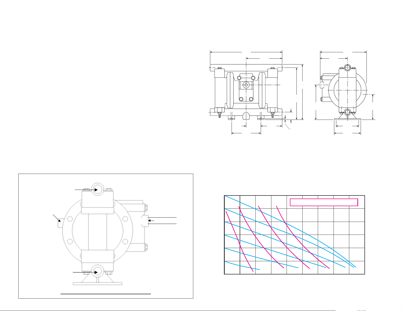
DIMENSIONS
Dimensions in inches and (mm)
10.86
(276,0)
4.40
(112,0)
DISCHARGE
INLET
2.20
(56,0)
5.43
(138,0)
3.23
(82,0)
PERFORMANCE CURVE
(Based on water-flooded suction)
1.13
(28,6)
7.82
(198,6)
5.43
(138,0)
8.34
(212,0)
5.21
(132,0)
AIR
SUPPLY
4.12
(105,0)
7.37*
(187,2)
3.24
(82,0)
4.00
(102,0)
EXHAUST
3.80
(96,5)
AIR
Typical Installation
DISCHARGE
Muffler (air exhaust)
is supplied with
each pump.
SUCTION
DO NOT USE AIR LINE LUBRICATION
Flexible Airline
AIR FLOW CONTROL
VALVE IS OPTIONAL
(USE TO MAINTAIN
MAXIMUM AIR
EFFICIENCY)
AIR FLOW CONTROL
VALVE PART NO:
13400-30
SUCTION AND DISCHARGE PORTS
CAN BE REPOSITIONED TO SUIT
THE APPLICATION
DISCHARGE FLOW-Liters/Min.
120
(8,2)
100
7,6 15,1 22,7 30,3 37,9 45,4 53,0 60,6 68,1
2
5
10
15
AIR CONSUMPTION - SCFM
(6,8)
80
(5,4)
60
(4,1)
40
(2,7)
20
(1,3)
PRESSURE INLET/OUTLET PSIG (BARS)
0 2 4 6 8 1012141618
DISCHARGE FLOW-U.S. Gals./Min.
276
(83,9)
230
(69,9)
184
(55,9)
138
(41,9)
92
(27,9)
46
(13,9)
 Loading...