

All-Flo KN-025 User Manual

1
⁄4˝CLASSIC PERFORMANCE
MAINTENANCE MANUAL
CHECK VALVE, GASKET AND O-RING MAINTENANCE
1. Flush and neutralize the pump to be certain all corrosives or hazardous materials are removed prior to any maintenance. This procedure should always be
followed when returning pumps for factory service also. Remove suction,
discharge and air supply lines.
2. Remove the 1/4-20 nuts (28) and slide the six cap screws (27) that hold the
pump together out of the pump. Remove the #8 screws (5) from the left and right
manifold plates (1,19) and inspect the gaskets (2). The suction (or lower) check
valves are an integral part of the left and right chambers and should not be
dismantled. If replacement of the valve seats is necessary, the left and right
chambers (6, 18) which contain the valves must be replaced. The upper
discharge disks (3) are not sealed into the chambers and may be inspected for
wear. If any components are worn or scratched, replace. Note: Due to the
distortion of gaskets under pressure, gaskets may need to be replaced after
pump has been disassembled to assure a positive seal
3. To inspect manifold tube o-rings (17) remove right chamber.
4. Both diaphragms (9) can be inspected after removing the left and right chamber.
If diaphragms appear worn or ruptured go to step 7. If diaphragms do not need
replacing, proceed with steps 5 and 6.
5. To reassemble: Insert the discharge valve disks into place. Press gaskets into
grooves in chambers.
6. Align left and right manifolds on
the bosses of the chambers.
Secure to each chamber with the
ten #8 screws. Tighten to 12 ft-
lbs (16,3 NM). Slide left chamber tubes through intermediate.
Position o-rings on the end of the
tubes. Lubricate o-rings and right
chamber holes. Slide a flat
Discharge
Valve Disk
Suction Valve Disk
is part of right and
left chambers
DIAPHRAGM MAINTENANCE
7. Remove outer diaphragm plates (7) by holding one diaphragm plate and twisting
off the other plate.
8. The diaphragm o-ring (8) is used only with PTFE diaphragms. Replace
diaphragms if ruptured or worn. Inspect inner diaphragm plates (10). If diaphragm
rod needs replacing go to step 10.
washer (26) onto each of the six
capscrews and insert through
the entire assembly. Secure with
a flat washer (26) and a tension
washer (29) under each nut.
Tighten to 5 ft-lbs (6,8 NM).
Apply torque evenly.
9. If no further inspection is necessary reassemble inner diaphragm plates and
diaphragms onto stud of outer diaphragm plates and screw each assembly into
diaphragm rod. (Make sure optional diaphragm o-ring is in position in the o-ring
groove on either side of the intermediate if using PTFE diaphragms. When positioning PTFE diaphragms make sure that the concave side is facing the wet
ends of pump.) Tighten outer diaphragm plates to 40 in-lbs (4,5 NM). Reassemble pump according to steps 5 and 6.
AIR VALVE AND DIAPHRAGM ROD MAINTENANCE
10. To remove the diaphragm rod twist the two rod halves apart by using a 7/16”
wrench on the flats at the end of each half. Pull each half out of the pump. Inspect for corrosion.
11. To inspect diaphragm rod lip seals (14) remove the two self tapping screws (12)
from the retaining plates (13). Gently remove lip seals and inspect for damage.
To reassemble, lubricate diaphragm rod lip seals (14) and insert into bore with
the u-cup portion facing inward. Note: Since the diaphragm rod passes through
the spring clip assembly (23), spring clip assembly must be removed prior to
reinsertion of the diaphragm rod into bore in intermediate.
12. To remove spring clip assembly firmly pull air valve plug (25) from pump.
13. Inspect spring clip assembly and shuttle (22) for damage. Surface of intermediate around air ports and flat surface of shuttle must be smooth, no scratches or
debris. Replace or clean if necessary.
14. Attach retainer plate with flat surface toward lip seals. Do not over tighten self
tapping screws.
15. To reinsert diaphragm rod halves, drop shuttle into intermediate over ports. Groove
in shuttle should be aligned vertically in pump and should face outward. Insert
spring side of spring clip assembly into groove in shuttle. At this point the assembly is not affixed to anything. Press down as shown below to insert long half of
diaphragm rod (16) through spring clip assembly and position under spring ends.
16. While continuing to apply pressure to spring clip assembly,
screw short half of diaphragm
rod (11) into long half.
17. Follow instructions for assembly of diaphragms in step 9.
Apply
pressure with
finger while
inserting and
assembling
the
diaphragm
rods.
19. Follow procedure for final assembly of pump in step 6.
Final tightening of diaphragm
rod will occur when outer
diaphragm plates are tightened.
18. Make sure valve plug o-ring (21)
is well lubed, position o-ring and
press air valve plug into the
intermediate making sure that
tab and indentation are aligned.
If o-ring is not well lubricated, it
will not permit reinsertion.
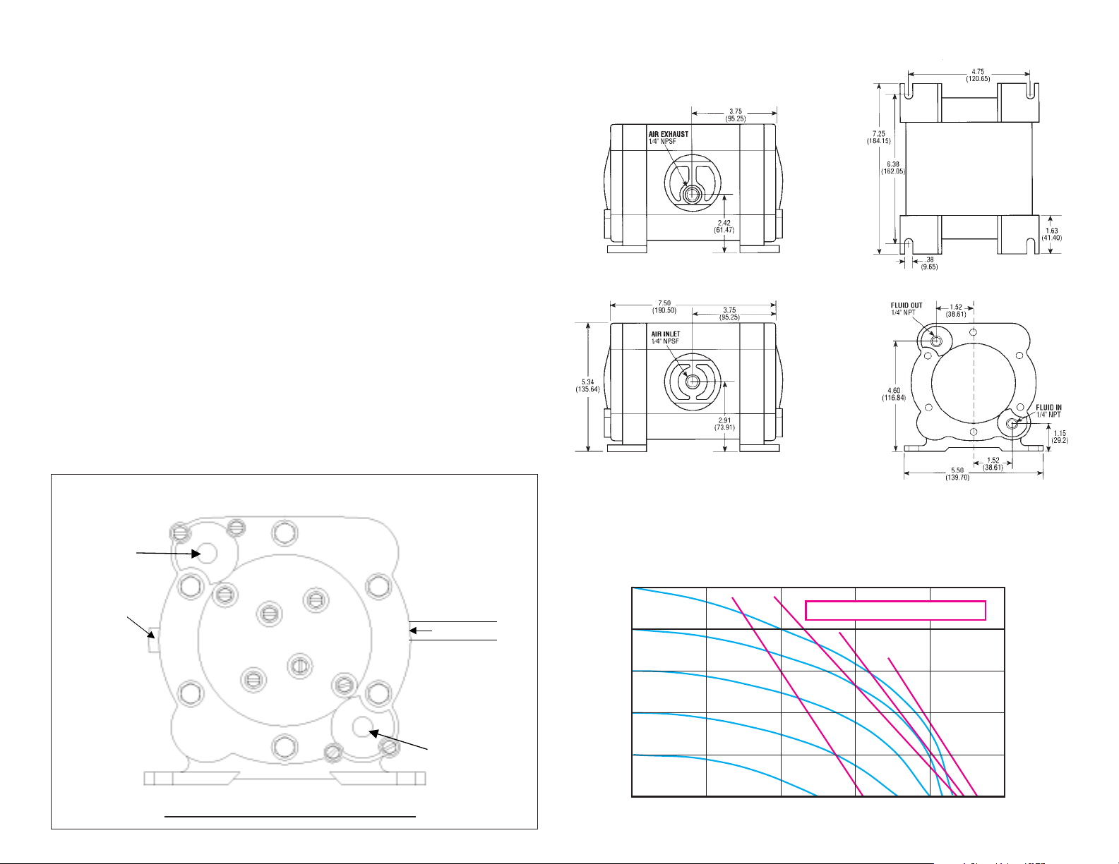
SPECIFICATIONS
CAPACITY:
Adjustable . . . 0 to 4.3 GPM (16,3 liters/min.)
MAXIMUM TEMPERATURE:
KN-025 Model . . . . . . . . . . . . . 200°F (93°C)
Other Models . . . . . . . . . . . . . . 150°F (66°C)
MAXIMUM AIR PRESSURE:
All Models . . . . . . . . . . . . . 100 PSI (6,8 bar)
DRY LIFT:
Other Models . . . . . . . . . . . . 17 ft. (5 meters)
WEIGHT:
KN-025 Model . . . . . . . . . . . . 7 lbs. (3,2 kg.)
Other Models . . . . . . . . . . . . . 5 lbs. (2,3 kg.)
Maximum Solids: . . . . . . 1/16” or (1,6 mm)
AIR SUPPLY:
Inlet . . . 1/4” NPT Female (BSP Compatible)
Outlet . . . . . . . . . . . . . . . . . 1/4” NPT Female
Fluid Inlet/Discharge: . . . . . . . . . .1/4” NPT
* Geolast properties are similar to that of
Nitrile (Buna-N)
DIMENSIONS
Dimensions in inches and (mm)
Rear View
Front View
Footprint
Typical Installation
DISCHARGE
Muffler (air exhaust)
is supplied with
each pump.
DO NOT USE AIR LINE LUBRICATION
Flexible Airline
AIR FLOW CONTROL
VALVE IS OPTIONAL
(USE TO MAINTAIN
MAXIMUM AIR
EFFICIENCY)
AIR FLOW CONTROL
VALVE PART NO:
134000-30
SUCTION
PERFORMANCE CURVE
(Based on water-flooded suction)
DISCHARGE FLOW-Liters/Min.
100
(6,8)
80
(5,4)
60
(4,1)
40
(2,7)
20
(1,3)
PRESSURE INLET/OUTLET PSIG (BAR)
02
3,8
DISCHARGE FLOW-U.S. Gals./Min.
7,6
2
1
Side View
11,4
AIR CONSUMPTION - SCFM
3
3
15,2
4
4
19,0
230
(69,9)
184
(55,9)
138
(41,9)
92
(27,9)
46
(13,9)
TOTAL HEAD IN FEET (METERS)
51
 Loading...