

All-Flo KE-038-B3 User Manual
3
⁄8˝SPECIALTY PERFORMANCE
MAINTENANCE MANUAL
BEFORE YOU BEGIN
Flush and neutralize the pump to be certain all corrosive or hazardous materials are removed prior to any maintenance. This procedure should always be
followed when performing maintenance, transporting used pumps or returning
pumps for factory service.
VALVE AND O-RING MAINTENANCE
1. Remove the nuts (3) and washers (4) from the bolts (23) in manifolds. Remove the
manifolds (20), (11). Two of the four max pass valves and back-ups (13, 14) are
located inside of the bottom of the outer chambers (16). Gently remove and inspect
for excessive wear, pitting or other signs of degradation. Inspect manifold o-ring (12)
as well and replace if necessary.
2. The other two max-pass valves are located inside of the bottom of the discharge
manifold (20). Repeat the procedure for inspection of discharge valves, back-ups
and o-rings. (Some pumps such as those built with PTFE have ball valves in place of
the max pass valves. Repeat the procedure—inspect valve seat (28), balls (29), ball
cage (27) and o-ring (12)).
3. When re-assembling the max-pass pump, the sleeve (15) should be assembled into
the valve cavity first, followed by the max-pass valve (13), the valve back-up (14) and
finally the o-ring (12). For pumps with balls valves, the cage (27) should be assembled into the valve cavity first, followed by the ball (29), valve seat (28), and
finally the o-ring (12). Lightly tighten all external fasteners when assembling, torquing
them to their requirements after pump is completely assembled.
NOTE: When using pumps built with PTFE o-rings, always replace with new
PTFE o-rings, since the original o-rings may not reseal the pump.
DIAPHRAGM MAINTENANCE
4. To inspect diaphragms, remove the nuts (7) from the carriage bolts (8) on the band
clamps (16) surrounding the outer pump chambers (16). If replacement is necessary
due to abrasion or rupture, unscrew the outer diaphragm plates (17). Only models
that have PTFE elastomers will have both a PTFE overlay (18) that faces the outer
pump chamber and an o-ring (25) on the air side of pump. (NOTE: Pumps that do not
contain PTFE will not have o-ring (25) – they are built with diaphragms (19) only.)
5. To inspect the diaphragm rod’s lip seals, remove diaphragm rod and carefully pick out the
lip seals from inside the intermediate (22). Replace if necessary. Be sure to reinsert the
lip seals with open cup facing the inside of the pump. Make sure that the rod guide is
facing the air valve assembly and slide the diaphragm rod back into intermediate.
6. Take one diaphragm and with the curved side of the inner diaphragm plate facing the
diaphragm, assemble onto the outer diaphragm plate stud. Screw the assembly into
the end of the diaphragm rod. Repeat for the other side. Torque the outer diaphragm
plates to requirements.
7. Position outer diaphragm chambers onto the intermediate, making sure that the witness line of the intermediate matches with the parting line of the chamber.
8. When positioning band clamps, use soapy water or a compatible lubricating spray on
the inside of the band clamps to aid assembly. Tap with a mallet on the outside of the
clamp to help position it while tightening the fasteners. The band clamp fasteners are
stainless steel. To prevent galling, apply an anti-seize compound to the thread. Tighten
to final torque requirements.
9. Position the manifolds, making sure of their orientation in relation to the air valve for your application.
Also, make sure that the manifold o-rings do not shift from their grooves during reassembly.
Tighten all external fasteners to final torque requirements after the pump is completely assembled.
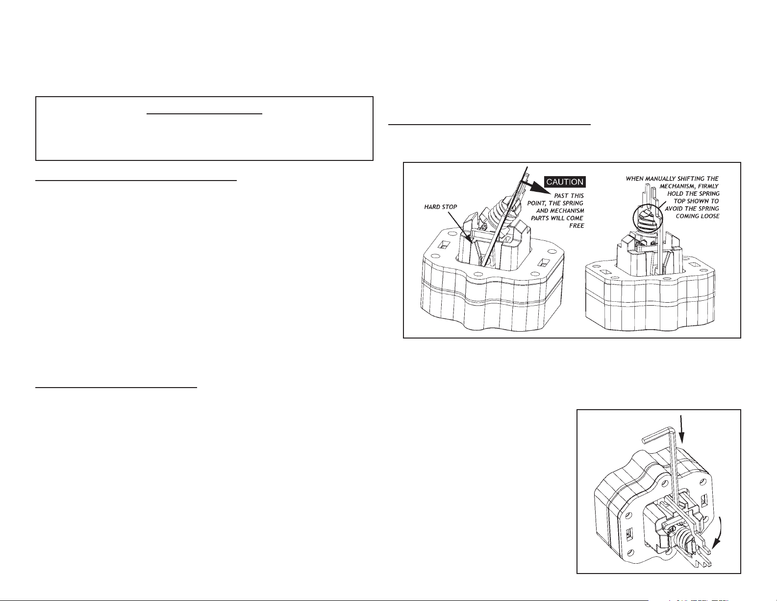
AIR VALVE ASSEMBLY INSPECTION
CAUTION: Only one side of the mechanism has a hard-stop. Shifting the mechanism past its operating position can cause the spring to pop free and internal
components to come loose. Use caution when shifting the mechanism manually.
10. If there has been a diaphragm rupture and fluid has entered the air side of the pump, the
complete air system should be inspected. Remove the air valve assembly (2) by
unscrewing the six long hex-head air valve assembly screws (9).
11. Clean or replace the air valve assembly if there is excessive wear, dirt build-up or chemical attack. Inspect for proper shifting of the spring mechanism by manually pushing the
metal spring retainer from one side to the other.
12. To reinstall the air valve, first shift the spring
mechanism to the side with the hard-stop.
Next, prop the spring retainer into a more
neutral position by inserting a 7/64” or 3mm
hex key as shown between the hard-stop
and the spring retainer.
13. With the rod guide (1) positioned such that
the opened end is facing the air valve assembly opening, slide the air valve assembly in place so that the forks slide into the
rod guide. Once the fork of the spring retainer is in the rod guide, pull the hex key
free and push the air valve assembly fully
into place. Finally, reinsert and tighten the
air valve assembly screws to the torque
listed on the specs sheet.
(Over)
FASTENER TORQUE REQUIREMENTS
NOTE: When reassembling, loosely tighten all external fasteners adjusting and
aligning. Then gradually, in an alternating fashion, tighten to the torque
requirements listed below.
AIR VALVE ASSEMBLY SCREWS 12 in-lbs (1,35 NM)
BAND CLAMPS 13.3 ft-lbs (18,8 NM)
MANIFOLD BOLTS, 10 in-lbs (1,13 NM)
OUTER DIAPHRAGM PLATES, 40 in-lbs (4,5 NM)
U.S. Patent Number 5232352
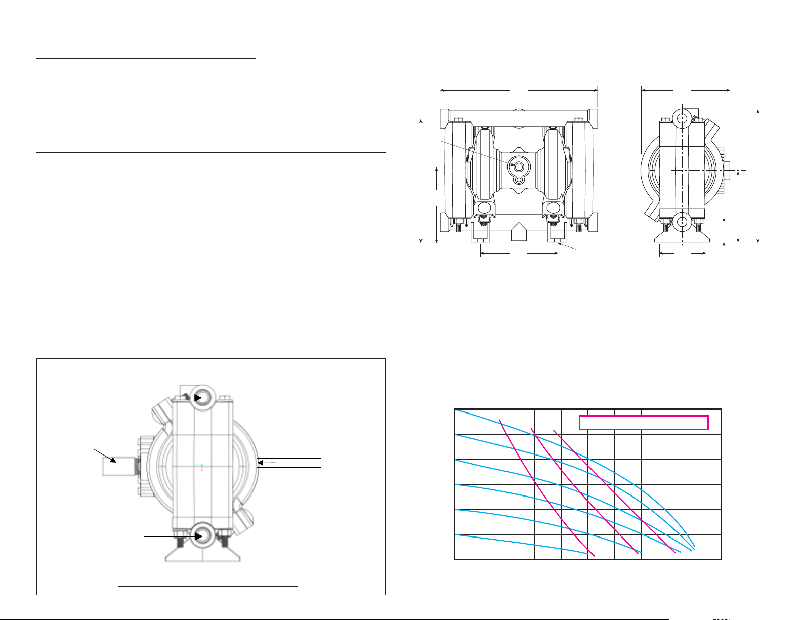
DIMENSIONS
Dimensions in inches and (mm)
8.55
(217,2)
AIR
INLET
DISCHARGE
4.82
(122,4)
7.19
(182,6)
SPECIFICATIONS
CAPACITY:
Adjustable 0-9 GPM (34,0 LPM)
MAXIMUM TEMP:
PVDF models – 200˚F (93˚C)
Other models –150˚F (66˚C)
MAXIMUM AIR PRESSURE:
120 psi (8,2 bar)
MINIMUM AIR PRESSURE:
20 psi (1,3 bar)
DRY LIFT:
Models with PTFE balls –
10 feet (3 meters)
Models with Max-Pass™ valves –
17 feet (5,2 meters)
Typical Installation
DISCHARGE
Muffler (air exhaust)
is supplied with
each pump.
SUCTION
DO NOT USE AIR LINE LUBRICATION
WEIGHT:
PVDF models – 5 pounds (2,3 kg)
Other models – 3.8 pounds (1,7 kg)
MAXIMUM SOLIDS:
Models with Max-Pass™ valves – 1/4˝
(6,4 mm)
Other models – 1/16˝ (3,2 mm)
AIR SUPPLY:
Inlet – 1/4˝ NPS Female
(BSP or NPT compatible)
Outlet – 3/8˝ NPS Female
(BSP or NPT compatible)
FLUID INLET/DISCHARGE:
3/8˝ NPS Female
(BSP or NPT compatible)
AIR INLET IS ON
SIDE WITH S.S.
INSERT AND
OPPOSITE AIR
VALVE ASSEMBLY
Flexible Airline
AIR FLOW CONTROL
VALVE IS OPTIONAL
(USE TO MAINTAIN
MAXIMUM AIR EFFICIENCY)
AIR FLOW CONTROL VALVE
PART NO: 13400-30
SUCTION AND DISCHARGE PORTS
CAN BE REPOSITIONED TO SUIT
THE APPLICATION
1.06
(26,9)
EXHAUST
3.86
(98,0)
6.63
(168,4)
4.06
(103,1)
4.21
(106,9)
R .15
(3,8mm)
SUCTION
2.40
(61,0)
NOTE: AIR INLET IS ON THE SIDE WITH STAINLESS STEEL
INSERT. THE AIR VALVE ASSEMBLY IS ON THE
OPPOSITE SIDE OF THE PUMP.
PERFORMANCE CURVE
(Based on water-flooded suction)
DISCHARGE FLOW-Liters/Min.
120
(8,2)
100
(6,8)
80
(5,4)
60
(4,1)
40
(2,7)
20
(1,3)
PRESSURE INLET/OUTLET PSIG (BAR)
3,8 7,6 11,4 15,1 18,9 22,7 26,5 30,3 34,1 37,9
3
10
6
AIR CONSUMPTION - SCFM
276
(83,9)
230
(69,9)
184
(55,9)
138
(41,9)
92
(27,9)
46
(13,9)
012345678910
DISCHARGE FLOW-U.S. Gals./Min.
TOTAL HEAD IN FEET (METERS)
 Loading...