

All-Flo A050 User Manual
PUMP OPERATIONS & MAINTENANCE MANUAL
A050 - 1/2 INCH AIR OPERATED DOUBLE DIAPHRAGM PUMP
all-o.com
TABLE OF
CONTENTS
SECTION 1 WARNINGS AND SAFETY PRECAUTIONS 3
SECTION 2 MODEL DESIGNATION MATRIX 4-5
SECTION 3 PRINCIPLES OF OPERATION 6
SECTION 4 DIMENSIONAL DRAWINGS 7-8
SECTION 5 PERFORMANCE CURVES
RUBBER DIAPHRAGMS ..............................................................9
TPE DIAPHRAGMS ........................................................................9
PTFE DIAPHRAGMS .....................................................................9
SECTION 6 INSTALLATION, TROUBLESHOOTING AND MAINTENANCE
OPERATION ..................................................................................... 13
MAINTENANCE ............................................................................14
SECTION 7 REPAIR, ASSEMBLY AND TORQUE SPECIFICATIONS
PUMP WET END REMOVAL ............................................ 14-15
AIR VALVE REMOVAL .........................................................16-17
PILOT VALVE REMOVAL .................................................. 18-19
TORQUE SPECIFICATIONS ....................................................... 19
SECTION 8 EXPLODED VIEWS AND PARTS LISTS 20-25
SECTION 9 ELASTOMERS AND REPAIR KITS 26
SECTION 10 WARRANTY AND REGISTRATION 27
INSTALLATION ................................................................................... 10-11
TROUBLESHOOTING ..................................................................12
2
all-o.com
CAUTIONS — READ FIRST!
READ THESE WARNINGS AND SAFETY PRECAUTIONS PRIOR TO INSTALLATION OR OPERATION.
FAILURE TO COMPLY WITH THESE INSTRUCTIONS
COULD RESULT IN PERSONAL INJURY AND OR
PROPERTY DAMAGE. RETAIN THESE INSTRUCTIONS
FOR FUTURE REFERENCE.
WARNING
must be properly grounded prior to handling
flammable fluids and/or whenever static electricity
is a hazard.
Pump, valves and all containers
WARNING
CAUTION
= Hazards or unsafe practices
which could result in severe
personal injury, death or
substantial property damage
= Hazards or unsafe practices
which could result in minor
personal injury, product or
property damage.
SECTION
1
WARNING
ensure that the air and fluid lines are closed and
disconnected. While wearing personal protective
equipment, flush, drain and process liquid from the
pump in a safe manner.
CAUTION
source to the exhaust port of the pump.
CAUTION
installed prior to pump operation.
CAUTION
CAUTION
aware of the following temperature limitations:
Buna-N (Nitrile): 10°F to 180°F (-12C to 82C)
Geolast®: 10°F to 180°F (-12C to 82C)
EPDM: -40°F to 280°F (-40C to 138C)
Santoprene®: -40°F to 225°F (-40C to 107C)
Viton® (FKM): -40°F to 350°F (-40C to 177C)
PTFE: 40°F to 220°F (4C to 104C)
Prior to servicing the pump,
Do not connect a compressed air
Ensure that the muffler is properly
Do not lubricate air supply.
When selecting pump materials, be
CAUTION
air-inlet pressure.
CAUTION
chemically compatible with the process fluid and the
cleaning fluid.
CAUTION
and flushed prior to installation into a process line.
CAUTION
Equipment (PPE) when operating pump.
CAUTION
compressed air and bleed all air from the pump
prior to service. Remove all process fluid in a safe
manner prior to service.
CAUTION
lines in order to remove any debris, prior to
pump installation.
CAUTION
atmosphere prior to a submerged installation.
Do not exceed 120 psig (8.3 bar)
Ensure all wetted components are
Ensure pump is thoroughly cleaned
Always wear Personal Protective
Close and disconnect all
Blow out all compressed air
Ensure air exhaust is piped to
Polyethylene: 32°F to 158°F (0C to 70C)
Polypropylene: 32°F to 180°F (0C to 82C)
PVDF: 0°F to 250°F (-18C to 181C)
Nylon: 0°F to 200°F (-18C to 93C)
Temperature limits are solely based upon
mechanical stress and certain chemicals will reduce
the maximum operating temperature. Consult a
chemical resistance guide for chemical compatibility
and a more precise safe temperature limit. Always
use minimum air pressure when pumping at elevated
temperatures.
CAUTION
correct torque values prior to operation.
Ensure all hardware is set to
all-o.com
3
SECTION
2
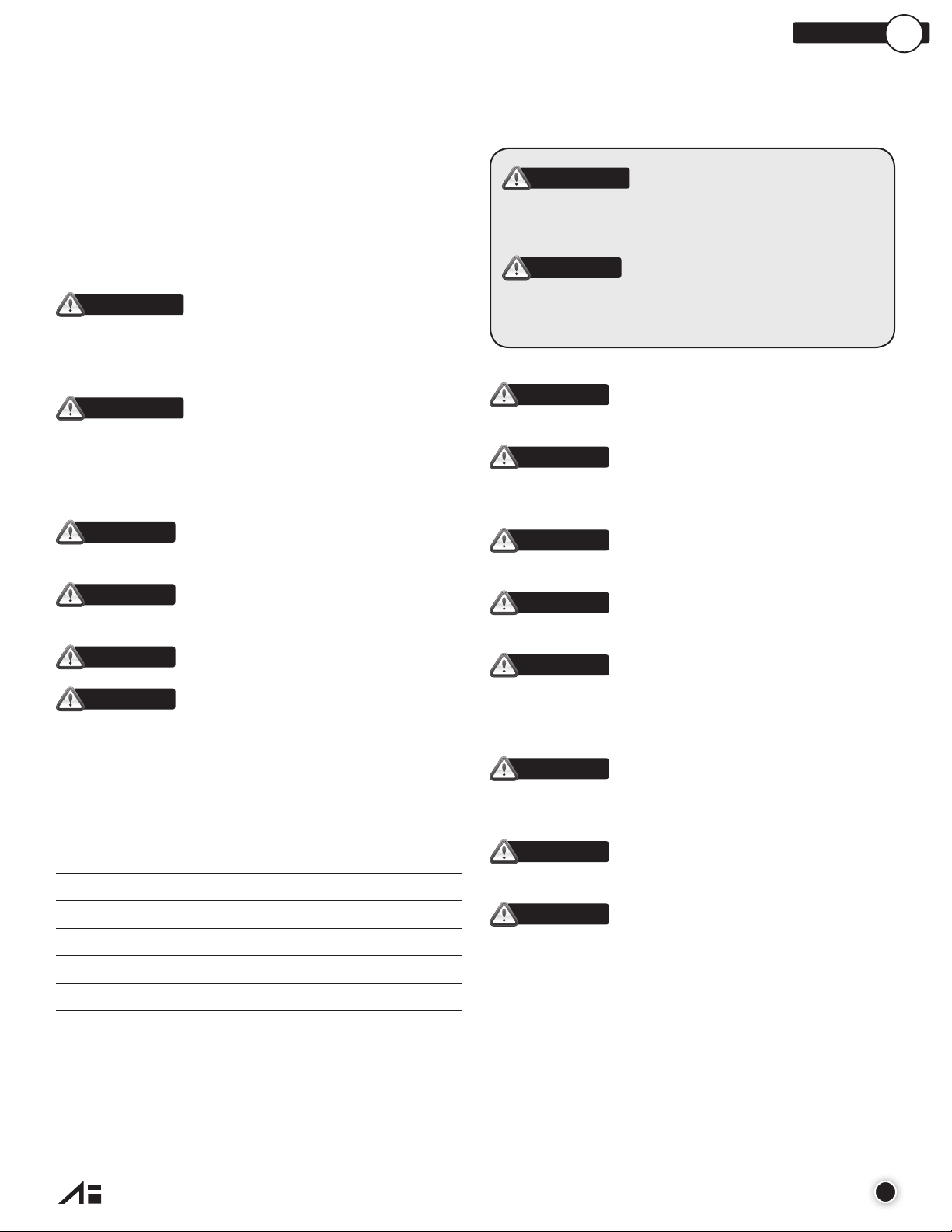
MODEL DESIGNATION MATRIX - ALUMINUM
PRODUCT SERIES
FLUID CONNECTION TYPE
FLUID CHAMBERS/
INTERMEDIATE/
INNER CHAMBER
SIZE
MANIFOLDS
DIAPHRAGM
VALVE/BALL
VALVE SEAT
O-RINGS
A 0 5 0 - 1 2 3 - 4 5 6 7 - 8 9 10
SPECIAL (HARDWARE,
MUFFLER, LUG)
PORTING
SPECIAL (OTHER)
FLUID CONNECTION TYPE
1
N = NPT
B = BSP
INTERMEDIATE / INNER CHAMBER
2
A = Aluminum
P = Polypropylene (Glass Filled)
FLUID CHAMBER / MANIFOLDS
3
A = Aluminum
DIAPHRAGMS
4
G = Geolast
S = Santoprene
T = PTFE with Santoprene® Backup
N = Buna – N
E = EPDM
V = Viton
VALVE/BALL
5
G = Geolast
S = Santoprene
T = PTFE
E = EPDM
V = Viton
3 = 316 Stainless Steel
®
®
®
®
®
®
WET END REPAIR KIT
Wet end kits are available and
consist of diaphragms, (back-up
diaphragms if required), balls,
seats and seat o-rings.
See matrix below.
PRODUCT
SERIES
WET END
REPAIR KIT
PUMP SIZE
VALVE SEAT
6
P = Polypropylene
3 = 316 Stainless Steel
A = Aluminum
K = PVDF
Y = Nylon
O-RINGS
7
N = Buna-N
E = EPFM
T = PTFE
®
V = Viton
PORTING
8
0 = Standard (Suction Right / Discharge Right)
T = Suction Right / Discharge Left
X = Suction Left / Discharge Right
Y = Suction Left / Discharge Left
A = Suction Center Front / Discharge Center Front
B = Suction Center Front / Discharge Center Rear
C = Suction Center Front / Discharge Top
D = Suction Center Front / Discharge Right
E = Suction Center Front / Discharge Left
F = Suction Center Rear / Discharge Center Front
G = Suction Center Rear / Discharge Center Rear
H = Suction Center Rear / Discharge Top
I = Suction Center Rear / Discharge Right
J = Suction Center Rear / Discharge Left
K = Suction Bottom / Discharge Center Front
L = Suction Bottom / Discharge Center Rear
M = Suction Bottom / Discharge Top
N = Suction Bottom / Discharge Right
O = Suction Bottom / Discharge Left
P = Suction Right / Discharge Center Front
Q = Suction Right / Discharge Center Rear
R = Suction Right / Discharge Top
U = Suction Left / Discharge Center Front
V = Suction Left / Discharge Center Rear
W = Suction Left / Discharge Top
1 = Dual Suction
2 = Dual Suction / Dual Discharge
3 = Dual Discharge
4 = All Ports Open (Standard ports will be left
un-plugged)
DIAPHRAGM
VALVE/BALL
VALVE SEAT
O-RINGS
SPECIAL OPTION (HARDWARE, MUFFLER, LUG)
9
0 = Standard (Zinc Plated Steel Hardware, Plastic
Muffler)
4 = Zinc Plated Steel Hardware, Metal Muffler
7= Stainless Steel Hardware, Plastic Muffler
8 = Stainless Steel Hardware, Metal Muffler
B = PTFE Coated Stainless Steel Hardware,
Plastic Muffler
C = PTFE Coated Stainless Steel Hardware,
Metal Muffler
D = Zinc Plated Steel Hardware, Plastic Muffler,
Grounding Lug Installed
E = Zinc Plated Steel Hardware, Metal Muffler,
Grounding Lug Installed
F = Stainless Steel Hardware, Plastic Muffler,
Grounding Lug Installed
G = Stainless Steel Hardware, Metal Muffler,
Grounding Lug Installed
H = PTFE Coated Stainless Steel Hardware,
Plastic Muffler, Grounding Lug Installed
I = PTFE Coated Stainless Steel Hardware,
Metal Muffler, Grounding Lug Installed
SPECIAL OPTION (OTHER)
10
0 = Standard (None)
1 = Cycle Counter Valve
2 = Solenid Adaptor Valve 110/50 Volt AC,
120/60 Volt AC
3 = Solenid Adaptor Valve 110/50 Volt AC,
120/60 Volt AC Explosion Proof
4 = Solenid Adaptor Valve 220/50 Volt AC,
240/60 Volt AC, 12 Volt DC
5 = Solenid Adaptor Valve 220/50 Volt AC,
240/60 Volt AC, 12 Volt DC Explosion Proof
6 = Solenid Adaptor Valve 220/50 Volt AC,
240/60 Volt AC, 125 Volt DC
7 = Solenid Adaptor Valve 220/50 Volt AC,
240/60 Volt AC, 125 Volt DC Explosion Proof
8 = Solenid Adaptor Valve 24 Volt DC
9 = Solenid Adaptor Valve 24 Volt DC,
Explosion Proof
A = Grease Free (No Lubrication Assembly)
AIR END REPAIR KIT
Air end repair kit contains pilot sleeve assembly, diaphragm rod and main air valve.
AIR END
PRODUCT
SERIES
REPAIR KIT
PUMP SIZE
MATERIAL
AWE - 050- 4567
Bold indicates recommended options
* Solenid Adaptor Valves only available on select pump models with polypropylene intermediate
all-o.com
4
AAK- 050-2
INTERMEDIATE / INNER CHAMBER
A = Aluminum
P = Polypropylene (Glass Filled)
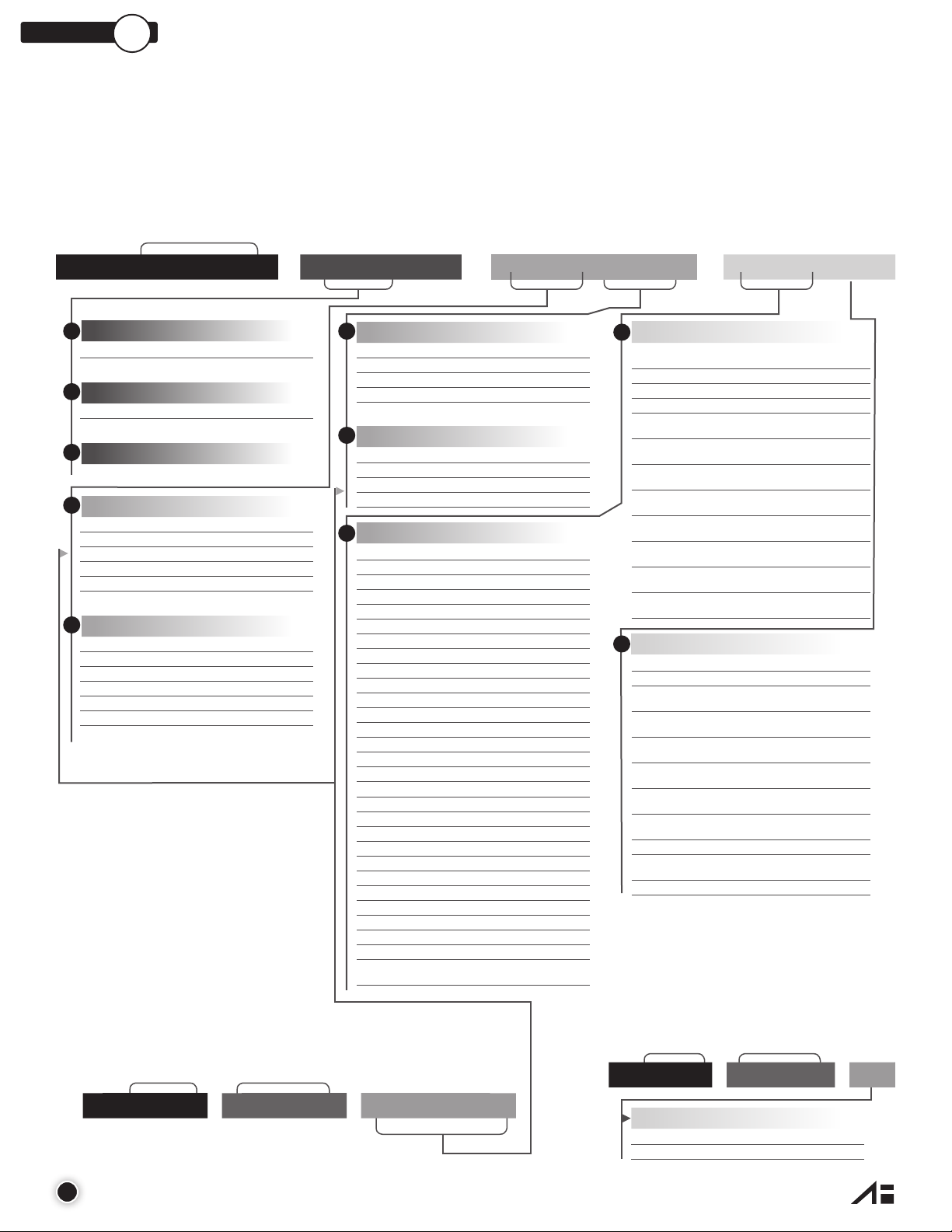
MODEL DESIGNATION MATRIX - STAINLESS STEEL
PRODUCT SERIES
FLUID CONNECTION TYPE
FLUID CHAMBERS/
INTERMEDIATE/
INNER CHAMBER
SIZE
MANIFOLDS
DIAPHRAGM
VALVE/BALL
VALVE SEAT
O-RINGS
A 0 5 0 - 1 2 3 - 4 5 6 7 - 8 9 10
SPECIAL (HARDWARE,
MUFFLER, LUG)
SPECIAL (OTHER)
PORTING
FLUID CONNECTION TYPE
1
N = NPT
B = BSP
2
INTERMEDIATE / INNER CHAMBER
P = Polypropylene (Glass Filled)
A = Aluminum
3
FLUID CHAMBER / MANIFOLDS
3 = CF8M Stainless Steel
4
DIAPHRAGMS
S = Santoprene
T = PTFE with Santoprene® Backup
N = Buna – N
E = EPDM
V = Viton
G = Geolast
5
VALVE/BALL
S = Santoprene
T = PTFE
E = EPDM
V = Viton
G = Geolast
3 = Stainless Steel
®
®
®
®
®
®
WET END REPAIR KIT
Wet end kits are available and
consist of diaphragms, (back-up
diaphragms if required), balls,
seats and seat o-rings.
See matrix below.
PRODUCT
SERIES
WET END
REPAIR KIT
PUMP SIZE
VALVE SEAT
6
3 = 316 Stainless Steel
P = Polypropylene
A = Aluminum
K = PVDF
Y = Nylon
O-RINGS
7
E = EPDM
T = PTFE
N = Buna-N
®
V = Viton
PORTING
8
0 = Standard (Suction Right / Discharge Right)
T = Suction Right / Discharge Left
X = Suction Left / Discharge Right
Y = Suction Left / Discharge Left
A = Suction Center Front / Discharge Center Front
B = Suction Center Front / Discharge Center Rear
C = Suction Center Front / Discharge Top
D = Suction Center Front / Discharge Right
E = Suction Center Front / Discharge Left
F = Suction Center Rear / Discharge Center Front
G = Suction Center Rear / Discharge Center Rear
H = Suction Center Rear / Discharge Top
I = Suction Center Rear / Discharge Right
J = Suction Center Rear / Discharge Left
K = Suction Bottom / Discharge Center Front
L = Suction Bottom / Discharge Center Rear
M = Suction Bottom / Discharge Top
N = Suction Bottom / Discharge Right
O = Suction Bottom / Discharge Left
P = Suction Right / Discharge Center Front
Q = Suction Right / Discharge Center Rear
R = Suction Right / Discharge Top
U = Suction Left / Discharge Center Front
V = Suction Left / Discharge Center Rear
W = Suction Left / Discharge Top
1 = Dual Suction
2 = Dual Suction / Dual Discharge
3 = Dual Discharge
4 = All Ports Open (Standard ports will be left
un-plugged)
DIAPHRAGM
VALVE/BALL
VALVE SEAT
O-RINGS
SPECIAL OPTION (HARDWARE, MUFFLER, LUG)
9
0 = Standard (Stainless Steel Hardware, Plastic Muffler)
8 = Stainless Steel Hardware, Metal Muffler
B = PTFE Coated Stainless Steel Hardware,
Plastic Muffler
C = PTFE Coated Stainless Steel Hardware,
Metal Muffler
F = Stainless Steel Hardware, Plastic Muffler,
Grounding Lug Installed
G = Stainless Steel Hardware, Metal Muffler,
Grounding Lug Installed
H = PTFE Coated Stainless Steel Hardware,
Plastic Muffler, Grounding Lug Installed
I = PTFE Coated Stainless Steel Hardware,
Metal Muffler, Grounding Lug Installed
SPECIAL OPTION (OTHER)
10
0 = Standard (None)
1 = Cycle Counter Valve
2 = Solenid Adaptor Valve 110/50 Volt AC,
120/60 Volt AC
3 = Solenid Adaptor Valve 110/50 Volt AC,
120/60 Volt AC Explosion Proof
4 = Solenid Adaptor Valve 220/50 Volt AC,
240/60 Volt AC, 12 Volt DC
5 = Solenid Adaptor Valve 220/50 Volt AC,
240/60 Volt AC, 12 Volt DC Explosion Proof
6 = Solenid Adaptor Valve 220/50 Volt AC,
240/60 Volt AC, 125 Volt DC
7 = Solenid Adaptor Valve 220/50 Volt AC,
240/60 Volt AC, 125 Volt DC Explosion Proof
8 = Solenid Adaptor Valve 24 Volt DC
9 = Solenid Adaptor Valve 24 Volt DC,
Explosion Proof
A = Grease Free (No Lubrication Assembly)
AIR END REPAIR KIT
Air end repair kit contains pilot
sleeve assembly, diaphragm rod
and main air valve.
AIR END
PRODUCT
SERIES
REPAIR KIT
PUMP SIZE
MATERIAL
AWE - 050- 4567
Bold indicates recommended options
* Solenid Adaptor Valves only available on select pump models with polypropylene intermediate
AAK- 050-2
INTERMEDIATE / INNER CHAMBER
P = Polypropylene (Glass Filled)
A = Aluminum
all-o.com
5
SECTION
3
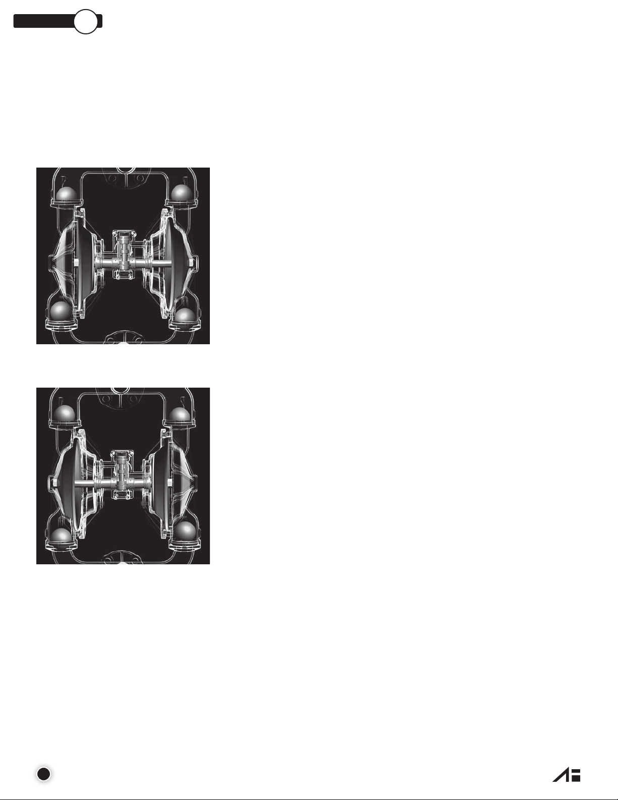
PRINCIPLES OF OPERATION
HOW AN AIR OPERATED DOUBLE
DIAPHRAGM PUMP WORKS
The air-valve directs pressurized air behind the diaphragm on the right,
causing the diaphragm on the right to move outward (to the right).
Since both the right diaphragm and the left diaphragm are connected
via a diaphragm rod, when the right diaphragm moves to the right, the
left diaphragm (through the action of the diaphragm rod) moves to the
right also.
When the diaphragm on the left side is moving to the right, it is referred
to as suction stroke. When the left diaphragm is in its suction stroke,
the left suction ball moves upward (opens) and the left discharge ball
moves downward (closes). This action creates suction and draws liquid
into the left side chamber.
The air-valve directs pressurized air behind the left diaphragm, causing
the left diaphragm to move outward (to the left).
Since both the left diaphragm and the right diaphragm are connected
via a diaphragm rod, when the left diaphragm moves to the left, the
right diaphragm (through the action of the diaphragm rod) moves to
the left also.
When the diaphragm on the left side moves outward, the left discharge ball
moves upward (opens) and the left suction ball moves downward (closes).
This causes the liquid to leave the left side liquid outlet of the pump.
Simultaneously, the right diaphragm moves inward (to the left), which
causes the right suction ball to open and the right discharge to close,
which in turn causes suction, drawing liquid into the right chamber.
The process of alternating right suction / left discharge (and vice-versa)
continues as long as compressed air is supplied to the pump.
6
all-o.com
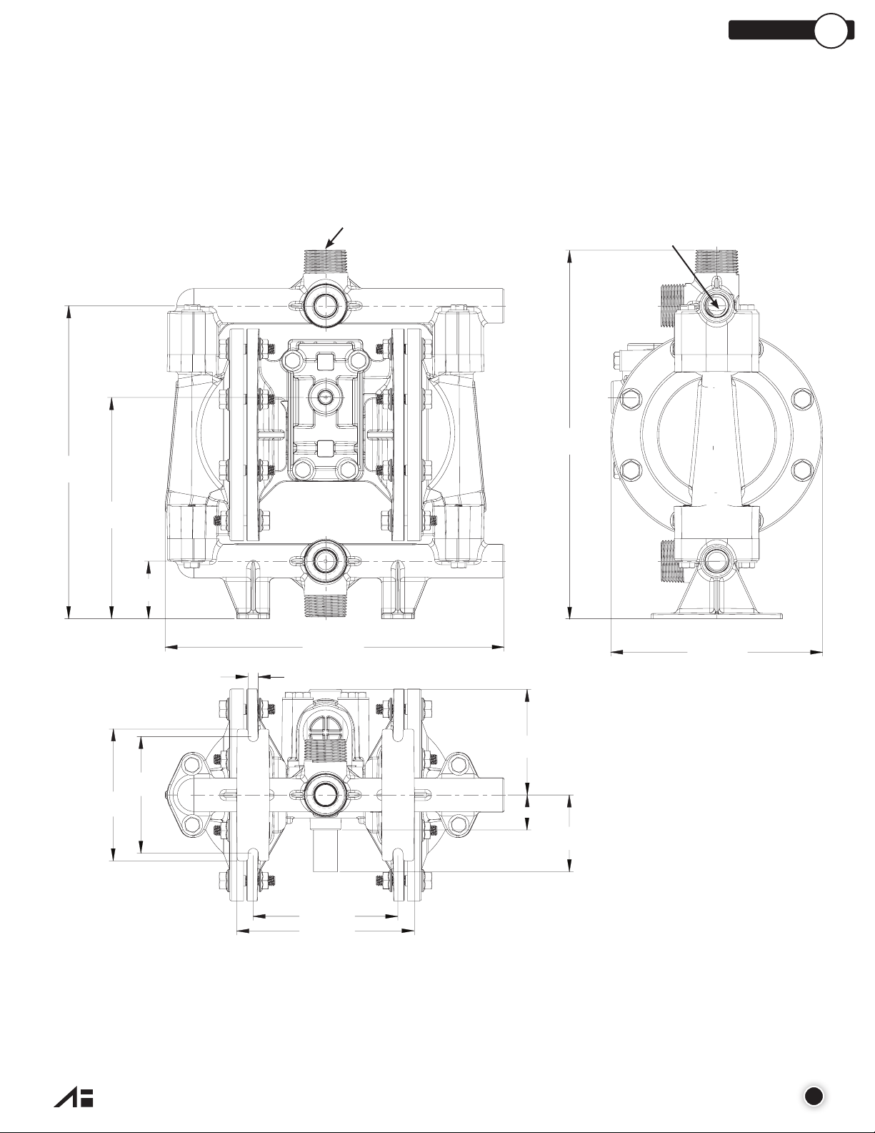
1/2” PUMP DIMENSIONS
(241mm)
5.4” (137mm)
ALUMINUM CENTER SECTION
SECTION
4
9.5”
6.7”
(170mm)
1.8”
(46mm)
1” MNPT OR 1” MBSP (x4)
1/2” FNPT or FBSP
11.2”
(284mm)
10.3” (262mm)
0.3” (8mm)
3.2”
(81mm)
3.6”
(91mm)
4.0”
(102mm)
4.4” (112mm)
1.1” (28mm)
Note - Suction Right / Discharge Right are default ports. See part number
matrix option code for additional porting options.
2.3”
(58mm)
6.4” (163mm)
all-o.com
7
SECTION
(241mm)
(160mm)
4
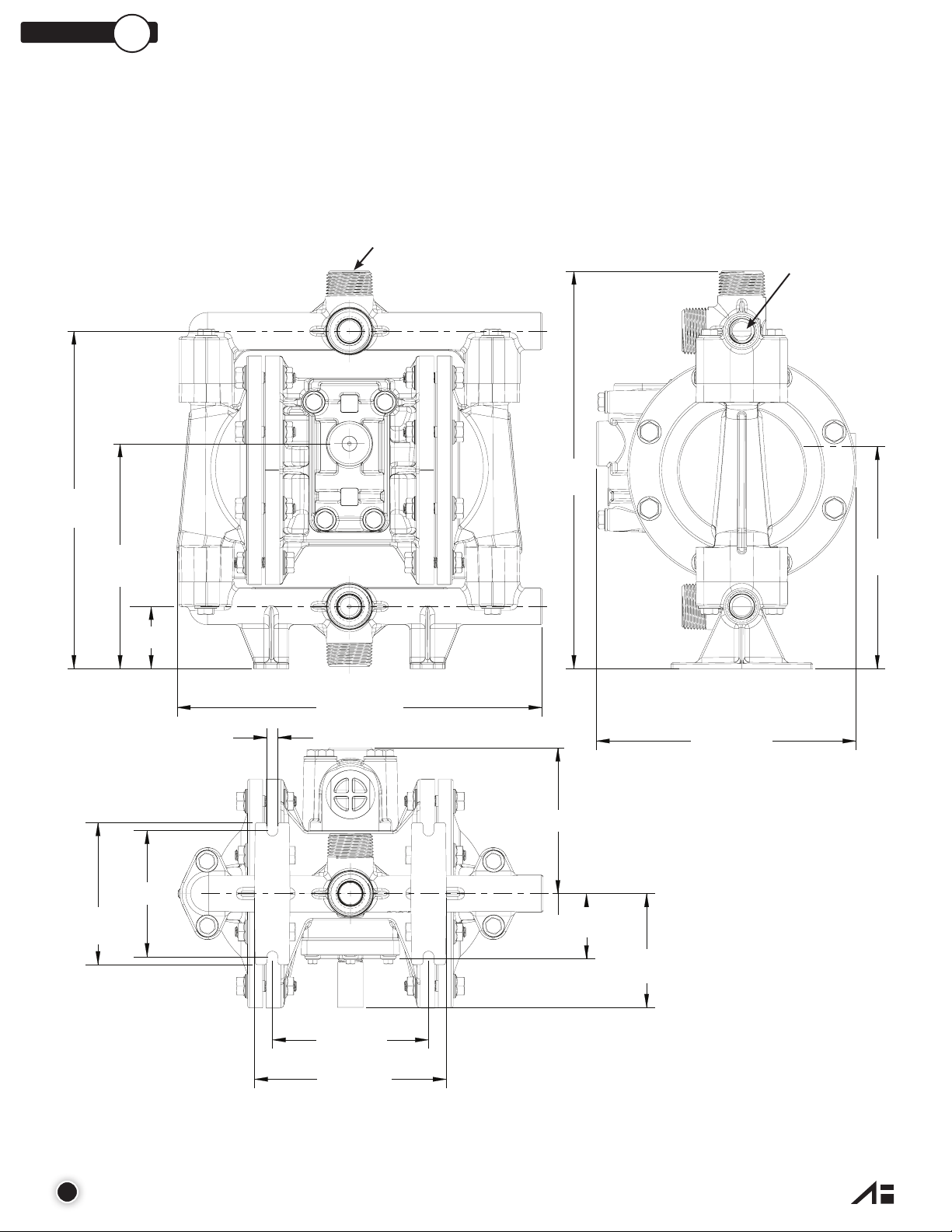
1/2” PUMP DIMENSIONS
POLYPROPYLENE CENTER SECTION
9.5”
6.3”
(160mm)
1.8”
(46mm)
1” MNPT OR 1” MBSP (x4)
11.2”
(284mm)
1/2” FNPT or FBSP
6.3”
10.3” (261.62mm)
0.3”
(8mm)
4.1” (104mm)
3.6”(91mm)
4.0”
(102mm)
4.4” (112mm)
5.4” (137mm)
1.8” (46mm)
Note - Suction Right / Discharge Right are default ports. See part number
matrix option code for additional porting options.
3.2”
(81mm)
7.3” (185mm)
8
all-o.com
PERFORMANCE CURVES
SECTION
5
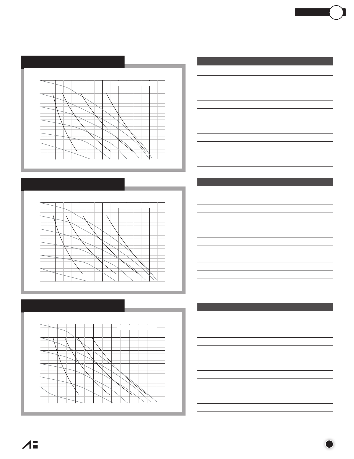
PERFORMANCE CURVE (1/2” RUBBER)*
DISCHARGE FLOW-Liters/Min.
120
(8,2)
100
(6,8)
80
(5,4)
60
(4,1)
40
(2,7)
20
(1,3)
PRESSURE INLET/OUTLET PSIG (BARS)
7.5 15.1 22.7 30.337.945.45360.6
02 46810121416
DISCHARGE FLOW-U.S. Gals./Min.
AIR CONSUMPTION (SCFM)
20 5 10 15
PERFORMANCE CURVE (1/2” TPE)*
DISCHARGE FLOW-Liters/Min.
120
(8,2)
100
(6,8)
80
(5,4)
60
(4,1)
40
(2,7)
20
(1,3)
PRESSURE INLET/OUTLET PSIG (BARS)
7.5 15.1 22.7 30.337.945.45360.6
02 46810121416
DISCHARGE FLOW-U.S. Gals./Min.
AIR CONSUMPTION (SCFM)
20 5 10 15
276
(83,9)
230
(69,9)
184
(55,9)
138
(41,9)
(27,9)
(13,9)
276
(83,9)
230
(69,9)
184
(55,9)
138
(41,9)
(27,9)
(13,9)
Performance Specifications
Max. Flow: 14 gpm (53.0 lpm)
Max. Air Pressure: 120 psi (8.3 bar)
Max. Solids:
1
/8” (3.2 mm)
Max. Suction Lift Dry: 15 ft-H2O (4.5 m-H2O)
Max. Suction Lift Wet: 31 ft-H2O (9.4 m-H2O)
Weight: AL-10 lbs (4.5 kg)/SS-20 lbs (9.1 kg)
Air Inlet: 1/4” FNPT
92
Liquid Inlet: ½” FNPT/BSP
Liquid Outlet: ½” FNPT/BSP
46
TOTAL HEAD IN FEET (METERS)
Height: 11.2” (284 mm)
Width: 10.3” (262 mm)
Depth: 6.4” (163 mm)**
Performance Specifications
Max. Flow: 15 gpm (56.8 lpm)
Max. Air Pressure: 120 psi (8.3 bar)
Max. Solids:
1
/8” (3.2 mm)
Max. Suction Lift Dry: 15 ft-H2O (4.5 m-H2O)
Max. Suction Lift Wet: 31 ft-H2O (9.4 m-H2O)
Weight: AL-10 lbs (4.5 kg)/SS-20 lbs (9.1 kg)
Air Inlet: 1/4” FNPT
92
Liquid Inlet: ½” FNPT/BSP
Liquid Outlet: ½” FNPT/BSP
46
TOTAL HEAD IN FEET (METERS)
Height: 11.2” (284 mm)
Width: 10.3” (262 mm)
Depth: 6.4” (163 mm)**
PERFORMANCE CURVE (1/2” PTFE)*
DISCHARGE FLOW-Liters/Min.
20 5 10 15
(8,2)
(6,8)
120
100
7.5 15.1 22.730.3
37.9
AIR CONSUMPTION (SCFM)
45.4
53
276
(83,9)
230
(69,9)
Performance Specifications
Max. Flow: 13 gpm (49.2 lpm)
Max. Air Pressure: 120 psi (8.3 bar)
Max. Solids:
1
/8” (3.2 mm)
Max. Suction Lift Dry: 14 ft-H2O (4.3 m-H2O)
80
(5,4)
60
(4,1)
40
(2,7)
20
(1,3)
PRESSURE INLET/OUTLET PSIG (BARS)
184
(55,9)
138
(41,9)
(27,9)
(13,9)
Max. Suction Lift Wet: 31 ft-H2O (9.4 m-H2O)
Weight: AL-10 lbs (4.5 kg)/SS-20 lbs (9.1 kg)
Air Inlet: 1/4” FNPT
92
46
TOTAL HEAD IN FEET (METERS)
Liquid Inlet: ½” FNPT/BSP
Liquid Outlet: ½” FNPT/BSP
Height: 11.2” (284 mm)
Width: 10.3” (262 mm)
02 468101214
DISCHARGE FLOW-U.S. Gals./Min.
*Flow rates indicated on all three charts shown were determined by pumping water at flooded suction, using an aluminum intermediate fitted pump.
For optimum life and performance, pumps should be specified so that daily operation parameters will fall in the center of the pump performance curve.
**Polypropylene intermediate is 7.3” (185mm) deep.
Depth: 6.4” (163 mm)**
all-o.com
9
 Loading...