

Page 1

1
Allevi 3
User Guide – 1.0.3
Page 2

2
B U I L D WITH LIFE
Page 3

3
Table of Contents
WELCOME 4
SPECIFICATIONS 5
SAFETY AND COMPLIANCE 5
GETTING STARTED 6
WHAT’S IN THE BOX 7
ALLEVI 3 DIAGRAM 8
SETTING UP YOUR PRINTER 9
SETTING UP YOUR SOFTWARE 12
START PRINTING 13
ALLEVI SOFTWARE: THE PROJECT WORKFLOW 14
PREPARING YOUR STL 15
BIOPRINTING IN THE DEVICE TAB 16
MAINTENANCE & TROUBLESHOOTING 21
TROUBLESHOOTING AND CONTACT US 21
Page 4

4
This User Manual will help get you started using your Allevi
bioprinter.
In the first section of this guide you will learn about the basic
components of your Allevi, how to set it up, download the
correct software, and load bioinks.
The second section of this guide will provide you with instructions
on using the Allevi software to print a single material structure.
The third section will teach you how to print a multimaterial
structure.
Finally, the fourth section will teach you how to bioprint for
your desired application.
Following this guide will help ensure that you are getting the
most out of your machine. We can’t wait to see what you will
create!
Page 5

5
SPECIFICATIONS
Mechanical
Dimensions: 33 x 33 x 45.7 cm
13 x 13 x 18 inch
Construction: Aluminum Frame
Build Structure: Tissue Culture Plates
XYZ Position Precision: 10 microns
Electrical
Power/Voltage Requirements: 6Amp AC
Desktop Adaptor
Connectivity: WiFi
Software
Bundle: Allevi Bioprint (WiFi)
Supported File Types: STL, gcode
Operating System: Windows, MacOSX, Linux
Printing
Print Technology: Fused Deposition
Manufacturing
Build Volume: 9 x 9 x 5cm (405 cm3),
3.5 x 3.5 x 1.97 inch (24.1 in3)
Layer Resolution: 100 microns
Print File Type: Gcode
Extruder
Max Temp: 160°C
Min Temp: 4°C
Pressure Range: 0-120PSI (0-820kPa)
LED Range: 365 nm or 405 nm
WARNING: The Allevi 3 includes moving parts that can cause injury. Never
reach inside the printer while it is in operation.
WARNING: Do not leave the printer unattended while it is in operation.
WARNING: Always wear safety goggles when using the printer.
WARNING: Extruders heat to high temperatures both when heating and cooling.
Always allow time for the extruder to cool before handling.
CAUTION: Always power off the printer before reaching inside.
Page 6

6
Let’s Get Started!
Page 7

7
WHAT’S IN THE BOX
Allevi 3 bioprinter
Power cord
Starter bioink kit
Safety glasses
Air compressor*
Compressor hose
*Air compressor arrives separately
Page 8

8
ALLEVI 3 DIAGRAM
A. Air Compressor Line
B. Swappable Extruder (heating and cooling)
C. Autocalibration pad
D. Build Plate
E. Power On/Off
Page 9
9
GETTING STARTED
Setting up your printer
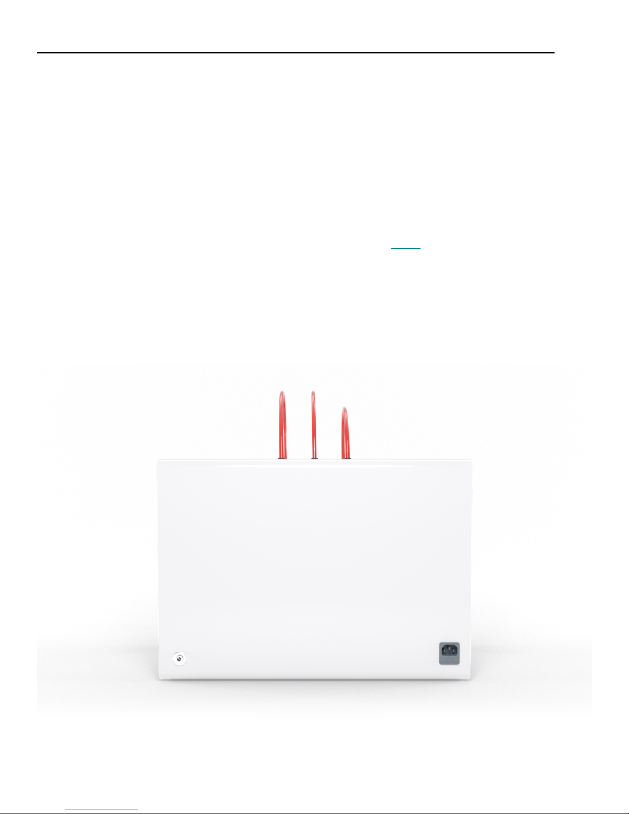
1. Carefully remove your printer from the packaging by grasping the printer frame firmly with
both hands.
2. Use the power cable to connect the printer to a power supply via the port located on the
right side of the printer (labelled Step 2).
3. Power on the printer by pressing the power button located front of the printer.
4. Attach the air compressor to the printer by connecting the compressor hose to nozzle on the
left side of the printer (labelled Step 4). This can be a tricky maneuver, so for more in depth
directions on connecting the air compressor, watch this quick video. The air compressor
must remain turned on for the entirety of the print. We recommend keeping the air
compressor set to a pressure significantly higher than your print pressure. This is so that as
the air compressor loses some pressure and refills, your print is not affected. The air
compressor’s pressure can be adjusted by turning the black knob. It has a max pressure of
120PSI.
Step 4
Step 2
Page 10
10
Setting up your software
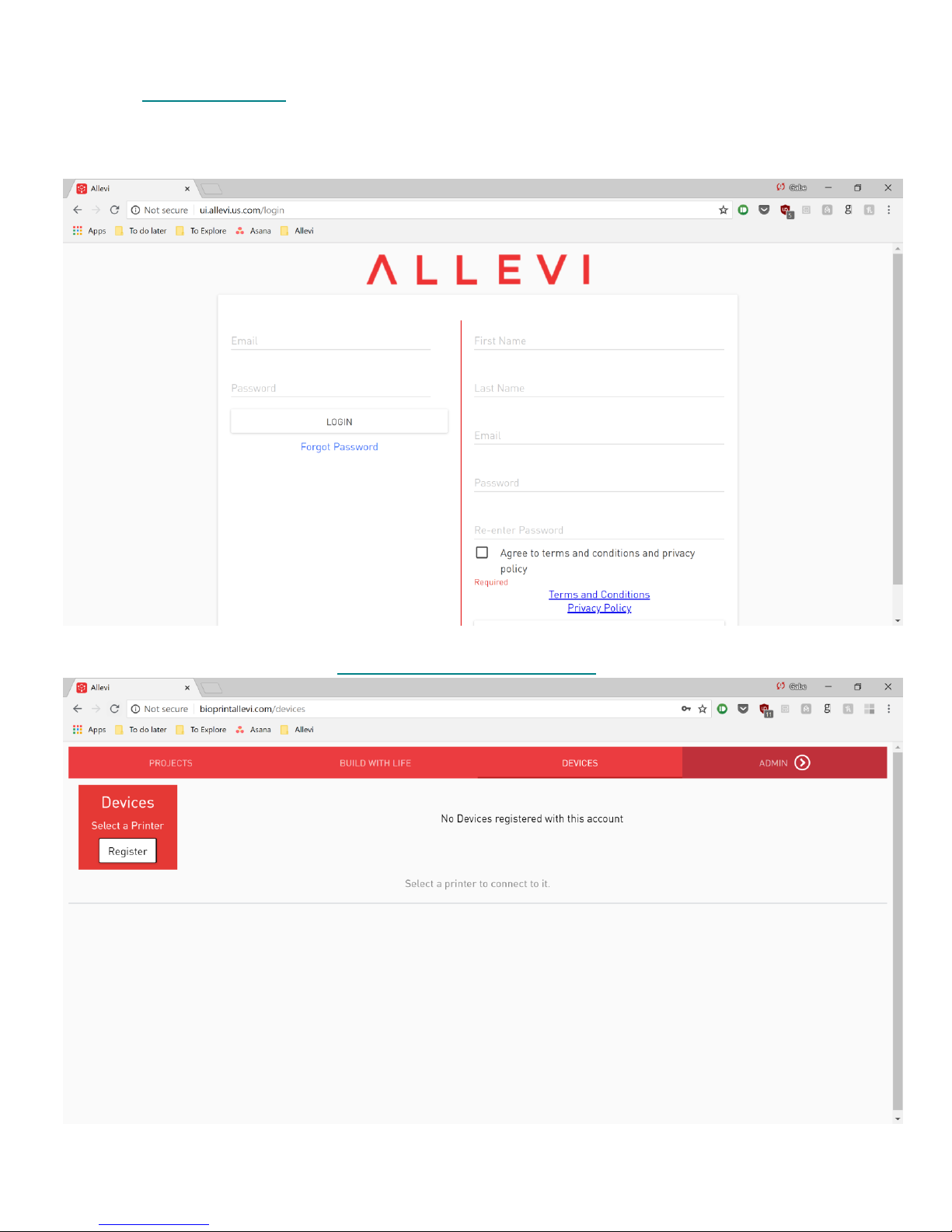
1. Go to bioprintallevi.com. Our software runs out of a browser and requires no downloads!
We recommend Google Chrome or Firefox, but any of the following browsers are also
acceptable: Safari, Opera, Edge, or Internet Explorer
2. To set up an account, fill out the form and click ‘Register.’
3. To register your printer, go to http://bioprintallevi.com/devices. Click ‘Register.’
Page 11

11
4. Next, type in your device number and click ‘Register’ again. Your device number can be
found in your onboarding email sent to you by the Allevi Support Team.
5. Once your printer is registered, it will appear as an available printer.
Page 12

12
6. To connect your Allevi bioprinter to the Internet, open your WiFi settings, and look for a
network called “WiFi Connect.” Connect to it, then go to the Offline Dashboard at
http://192.168.42.1:8007. By connecting to this, your computer will briefly lose access to the
Internet. Here you can either connect your printer to your WiFi network or connect to the
Offline Interface.
a. To connect to WiFi, choose your WiFi network from the dropdown menu under
‘SSID,’ type in the password, and hit connect. The chosen WiFi network should
be a private network. Your computer’s WiFi will be restored and your printer will
connect to the Internet.
b. To connect to the Offline Interface, click on the button on the righthand side. Note,
you will not have access to the Internet while connected to the Offline Dashboard.
Page 13

13
Let’s Start Printing!
Page 14

14
INTRODUCTION TO THE ALLEVI SOFTWARE
The Allevi software is designed with the 3D printing scientist in mind. It houses the various projects
you’re working on and makes them easily accessible. In a project you can store data, notes, pictures,
and prints.
The Allevi software also hosts other projects, from Allevi and other community members. You can
copy a public project into your explorer, allowing you to replicate and modify others’ studies.
Page 15
15
YOUR FIRST BIOPRINT
Preparing your STL
You can design STL files on any CAD software, such as SolidWorks or Autodesk Fusion 360. STL
files can also be created using sophisticated programs or 3D scanners. Alternatively, you can find a
host of STL files in the “Print files” category of Build With Life. There are also many 3D models
available on the internet. To begin, we will use a predesigned STL file.
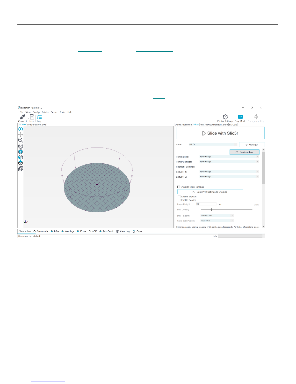
The Allevi software project workflow incorporates a built-in slicer. However, for now, we will use
Repetier-Host as our slicing software. Repetier-Host is a third-party software that converts STL files
(3D models) into gcode files (instruction the printer can read).
You can find the instructions for using Repetier-Host here or on the Allevi Protocols page.
Page 16

16
Printing your STL in the Device tab
In the Allevi software, there are 3 workflows for printing: Project workflow, the Devices tab, and the
Offline Interface. In this section, we’ll look at printing via the Devices tab.
1. Turn on your printer. Yellow lights will stay on while the printer loads its firmware and connects to
the Internet. You can connect to your printer once they are off and it’s connected.
2. Login to bioprintallevi.com and go to the ‘Devices’ tab. Select your printer (which should be
already registered) and click ‘Connect.’
3. Load your syringe with Pluronic F127. Visit the Allevi Protocols page to watch a video on how to
load syringes for your Allevi 3. We suggest filling your syringe with about 3 ml of material for your
first print:
a) Attach a 30 gauge 0.25” (pink) needle to the syringe, load syringe into the extruder
cannister, and twist the cap to secure.
NOTE: Bioinks will be loaded differently and use different needles depending on the type
of material.
Page 17

17
4. Select your wellplate and then activate your extruders by clicking on the red extruder button.
7. Now that you’ve activated your extruder, you can test its extrusion, move it around (in the
‘Jog Panel’), or calibrate it.
a. For autocalibration, click the ‘Autocalibrate’ button. (Autocalibration takes ~2 minutes
and will avoid the need for the ‘Jog Panel’.) For short needles, only add the
wellplate after autocalibration is complete, otherwise the extruder will crash.
Page 18
18
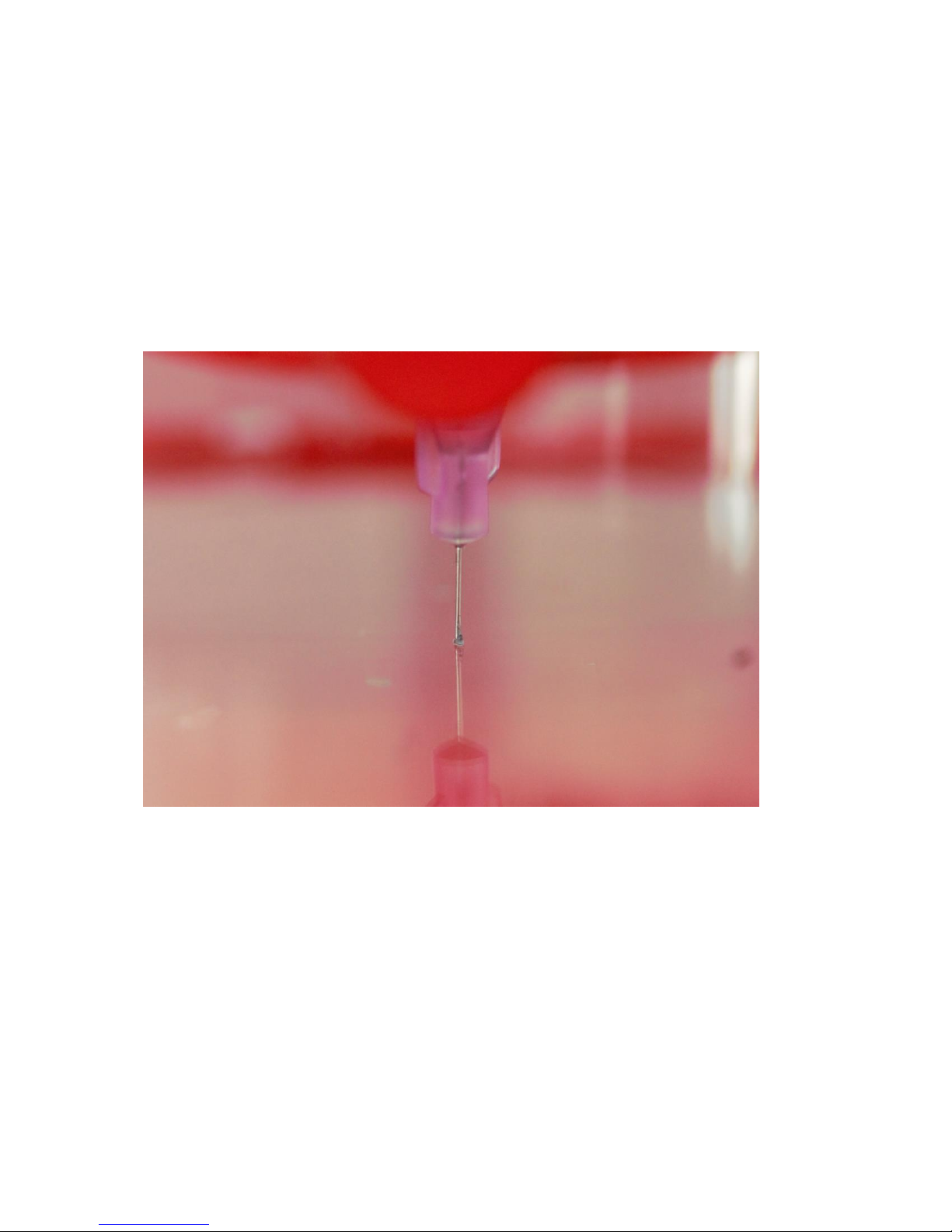
b. To manually calibrate the printer, use the Jog Panel.
i. First, home the Z axis, followed by the X/Y axis.
ii. Using the X and Y arrows, move the loaded extruder to over where you want
to print. If it’s for a wellplate, calibrate in the upper left well. We recommend
using the 20mm step size.
iii. Switch step size from 20mm to a smaller size, depending on the needle
length. Then use up and down buttons to move the bed plate (Z) closer to the
extruder to the point where the dish is almost touching the needle. Do not
leave a big gap between the needle and dish as the gcode automatically
adds the appropriate layer height. Finer 0.1mm movement can be used
when approaching the dish.
iv. Click ‘Set Calibration.’ to calibrate.
Page 19

19
5. For photocurable bioinks, the Allevi 3 offers both UV and visible light crosslinking, which can be
changed using the UV/Visible toggle. There are three main settings for crosslinking: Always On,
During Print, and Post Print. They use variables such as light intensity, layer frequency, and
duration.
6. Click the ‘Upload’ button to upload a .gcode file from your computer. It will render a rotatable, 3D
visualization of the extruder path.
Page 20

20
7. Once the wellplate, calibration, and gcode file are all ready, you can press ‘Start Print’ to start
building with life!
a) Note: As the printer loads the gcode, the printer’s yellow lights will turn on.
8. Sit back and watch your printer go!
Page 21

21
TROUBLESHOOTING AND MORE INFORMATION
When you buy an Allevi bioprinter, you’re not just getting a biofabrication platform; you’re gaining
the Allevi Advantage, which is all the experience and expertise Allevi has to offer.
One very useful resource is Allevi’s Build With Life repository. We upload protocols, experiments, and
guides to help you be more successful with bioprinting.
You can also visit the Allevi YouTube channel for video instructions.
Have more questions or need help?
Visit us on the Allevi Support page or email us at [email protected]!
Page 22

22
Allevi, Inc | 3401 Grays Ferry Ave | Building 176 | Philadelphia PA | 19146
Copyright Allevi, Inc 2018
Page 23

23
 Loading...