

Page 1
ZEDi-8 8 Channel Live + Recording Mixer User Guide
Thank you for purchasing this Allen & Heath ZEDi-8.
We recommend that you read all of this user guide to get the best from your mixer and after
reading, please keep this safe for future reference.
Included in this package is:
ZEDi-8 Mixer
IEC C5 Mains Power Cable. Please check correct mains plug is fitted for your country.
This User Guide!
1. Get to know your mixer
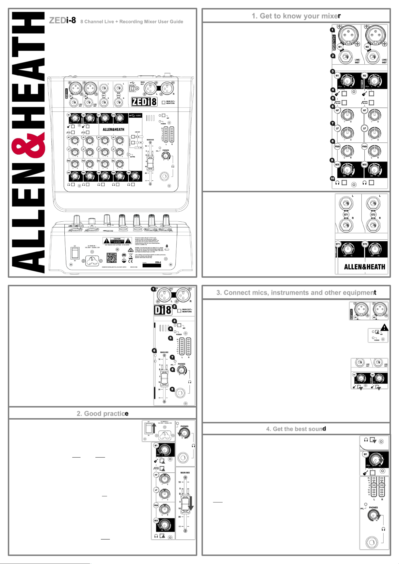
1.1 MONO INPUT CHANNELS (M)
1. Mic Input Socket uses a s tan dar d 3-Pin XLR socket for connecting dynamic
or condenser microphones.
2. Line / Inst Input Socket uses a standar d 1/4” (6.25mm) Jack so ck et for
connecting balanced or unbalanced signals such as guitars and other
instruments.
3. Gain Control adj us ts the gain of th e input pr eamplifier to dr ive the
source signal level. Gain ranges from 5dB to 60dB.
4. Instrument act iv ates the Line / Inst input ci rc uit fo r el ect ro -acoustic and
electric guitars, basses and other Direct Input instruments. When activated
the Mic Input Socket is disabled.
5. lo-cut (Hi-Pass Filter) is used for reducing Low Frequency noise such as
handling noise, popping, rumble and proximity effect in microphone signals.
6. HF EQ (Hig h Frequency) equ ali ser affects tr ebl e frequenci es i n the
signal for adding “brightness” and “definition” or for reducing “hiss” and
“harshness”.
7. LF EQ (Lo w Frequency) equ ali ser affects bas s f requencies in the signal
to cover “boom” and “sub-bass” frequencies.
8. PAN adj usts s ig nal from a m on o i np ut chan nel bet ween the left and
right busses and subsequently the main outputs.
1.3 MASTER SECTION
1. MAIN OUT L & R are lin e lev el o utput s f or the main st ereo mi x using s tan dard XLR
output connectors and are impedance balanced for rejection of unwanted interference.
2. MAIN OUT = MONITORS switch es t he PFL s ig nal to the MAIN OUT as well as the
PHONES output fo r f lex ible moni tori ng o f i np ut sig nal s t hroug h y our speaker s.
This is mainly for studio control room monitoring applications.
3. 48V switches in dustry s tan dard 48V (p hantom po wer ) to both m ic ro phone inp ut s for
use with condenser microphones.
4. POWER LED in di cates that t he m ixer is swit ch ed on.
5. LR Meters di splay the l evel of the MAIN MIX or th e mo no PFL si gnal if act iv ated by
any of the PFL switches.
6. MAIN MIX is th e master vol um e control fo r t he main s ter eo m ix.
7. PFL (Pre-Fade Listen) LED i ndicates w hen a PFL sw it ch has been pres sed on one of
the channels.
8. PHONES level cont rols the vol um e of signal to the PHONES output.
Warning! To av oi d damage to y ou r h earing d o n ot oper ate h eadp ho nes or sou nd system
at excessively high volume. Continued exposure to high volume sound can cause frequency
selective or wide range hearing loss!
!
9. PHONES output us es a s tan dar d 1/4” (6.25mm) jack so cket.
9. MIX ro tary fad er c ontrols th e amo unt of si gn al to the lef t an d righ t
busses.
10. Pre-Fade Listen (PFL) switch es t he c hannel i np ut signal to th e
headphones for checking before adding it to Mix. The PFL signal is taken
after the EQ but before the MIX control.
1.2 STEREO INPUT CHANNELS (ST)
ST1 and ST2 Inputs us e st andard 1/4” (6.25mm ) Jac k s oc kets fo r b alan ced or
unbalanced line level stereo sources such as professional keyboards, drum
machines and other pro audio equipment.
ST1 and ST2 Gain Control adj us ts the inp ut lev el to the ch ann el.
HF and LF EQ are t he same f or ST1 & ST2 as they are fo r M1 & M2 an d ar e set
at the same frequencies.
BAL adjusts t he r elat ive level bet ween th e left and ri ght stereo si gnals as they
are sent to the left and right busses and subsequently the main outputs.
3. Connect mics, instruments and other equipment
3.1 Connecting Microphones
Dynamic or condenser microphones and DI boxes should be connected to the Mic Input Socket
using a balanced XLR Microphone cable.
If you‘re using a condenser microphone, it will require 48V Phantom Power to work.
Some active DI boxes may also require phantom power.
Avoid ‘hot plugging’ when connecting any equipment and make sure AUX MASTER and MAIN MIX controls
are turned down before 48V is switched on as this as may cause loud thumps and bangs!
3.2 Connecting Instruments and Line-Level Equipment
High-Impedance (Hi-Z) instruments such as electro-acoustic guitars, basses and other Direct
Input instruments should be connected to Line / Inst Inputs on channels M1 & M2 usi ng a jack to
jack instrument cable, and do not require an additional DI box or preamp.
The Instrument switch must be activated to match extremely high impedance signals (10MΩ)
from instrument pickups.
Line level instruments such as keyboards, synthesizers, drum machines or equipment such as
external effect processors can be connected to Line / Inst Inputs on channels M1 & M2, and LINE input s o n M3 & M4 fo r
mono sources or ST1 & ST2 for ster eo s ources.
2. Good practice
2.1 “Zeroing”
It’s good practice to “zero” your mixer and turn down relevant channels before
connecting any devices as this prevents potential damage to speakers or other
equipment.
Follow these steps to make sure you’re safe and you avoid thumps and bangs when
plugging equipment in.
Speakers should always be switched ON LAST and OFF FIRST!
1. Make sure the power switch on the rear of the mixer is set to “OFF”
2. Connect the AC Mains Lead provided to the AC MAINS IN socket on the rear of the
mixer.
Check that the correct mains plug is fitted for your country and plug the AC Mains Lead
into a standard household mains socket.
3. Turn channel Gain controls all the way down (left).
4. Make sure Instrument, HPF, PFL and 48V sw itches are not pr essed in.
5. Set all channel EQ and PAN controls to the centre position marked “▼”
6. Turn all FX send, AUX send and MIX controls all the way down (left).
7. Lower the MAIN MIX fader to “∞”.
8. Turn down the PHONES level.
9. Double check speakers or amplifiers are switched off!
10. Connect speakers, instruments and other equipment.
11. Switch on instruments and other equipment, then mixer, THEN speakers !
Speaker or amp volumes should be set according to manufacturer guidelines. !
For channels M3 & M4 th e LINE/PAD swit ch mu st be act iv ated .
Follow the application examples in Section 7. for connecting devices to relevant input and outputs .
4. Get the best sound
4.1 Gain Structure
1. Once you’ve connected your instruments and equipment you will need to set input levels before
you can mix the signals together.
2. Gain structure is important to get the maximum signal level without undesirable distortion.
Setting gain properly helps to optimise signal quality and ensure that the signal to noise ratio
remains as low as possible.
3. If you‘re using a microphone make sure the mic is placed at an appropriate distance to the sound
source. (Close for quiet sources, further away for louder).
4. Press the PFL switch on the corresponding channel. This will allow you to hear the pre-fader
input signal and will show the signal level on the LR Meters.
5. Sing, talk or play your instrument at a typical level of loudness.
6. Slowly raise the Gain Control on the corresponding channel until you see a good signal level in
the LR Meters. Maximum peaks between “0” and “+6” on the meters are a good indicator.
7. Connect professional monitoring headphones to the Phones output and t urn up the
PHONES level to a saf e listening v ol ume.!
8. If the signal sounds undesirably distorted at a low signal level, enable any pad switch on the
microphone, or move the microphone further away from the source and repeat the process.
Once you’re happy with the input signal level, you may wish to use lo-cut (Hi-pass Filter) and the EQ
to enhance intelligibility or to remove unwanted frequencies, and improve the tonal balance of the
source sound, so keep the channel PFL switch enabled for now!
Section 4. continued overleaf...
Page 2
4.2 Shaping Sound
Dynamic or
Condenser
Microphone
Electro Acoustic
Guitar
Electronic Piano
Drum Machine
Active Studio Monitors
Microphone
Electro Acoustic
Guitar
Electronic Piano
Powered PA Speakers
Portable Media
Player
PC
iPad
EQ fil ter s au di o passi ng through it and allows yo u to ‘cut ’ (t urn down ) or ‘boost’ (turn up) s elec ted frequenci es.
‘Boosting’ a frequency too much may cause the signal to clip or distort. ‘Cutting’ a frequency will cause a reduction in
signal level.
Overuse of EQ may cause the sound to be unnatural. Understanding the frequency
responses of different instruments and how they might overlap will help you make
good decisions on how to EQ musically.
1. lo-cut (Hi-pass Filter) removes unwanted low frequency noise such as rumble,
handling noise, thumps and proximity effect and helps maintain clarity in the
signal. lo-cut aff ect s b oth Mic and Line/Inst inputs . The c or ner frequen cy
is set at 100Hz.
2. HF EQ (Hig h Frequency) aff ects trebl e fr equ encies in t he s ignal. The
corner frequency is at 12kHz for adding “brightness” and “definition” to guitars or
for reducing “hiss” in vocals and “harshness” in cymbals.
3. LF EQ (Low Fr equ enc y) equali ser aff ect s bass freq uen cies in th e si gnal.
The corner frequency is 80Hz for adding “roundness” and “sub-bass” to bass
guitar or kick drum, or to remove “boom” from toms.
When you’re happy with the input signal level and tone you can disable the
channel’s PFL switch and think about how to mix all these sounds together!
4.3 Balancing the Mix
Once you have set input gain levels and applied EQ to source signals, you can start to mix all of your
channels to the outputs. Consider the importance of each instrument and how they should be heard in the
mix.
5. ZEDi USB Audio Interface
5.1 USB AUDIO INTERFACE
A built-in 2 in, 2 out, 24-bit/96kHz USB Audio Interface allows for studio-quality recording direct from your
mixer to your PC without the need of any additional equipment. This is class-compliant (plug-and-play) for
Mac and iOS devices. (iOS devices require a camera connection kit).
Simply connect a USB cable between the USB port on the mixer and the USB port on your computer or
device. For Windows systems, driver software must be installed in order for it to work.
The latest driver software and documentation can be found at http://www.allen-heath.com/downloads
1. USB connector is a Typ e-B USB connector for multi-channel bi-directional audio streaming between
the mixer and a computer and follows the high speed USB 2.0 standard.
2. USB OUT SOURCE SELECT b utton s al lo w you t o c hose where the s ig nal to the o ut puts of t he
USB interface output is taken from.
3. M1- M2 selec ts the USB OUT so urce from ch ann els M1 & M2 dir ect ly and has pri or it y over t he
L-R PRE so urce select sw it ch.
4. L-R PRE sel ects the USB OUT s ource to be bef or e (pre) the MAIN MIX fad er for recording the LR stereo mix without the signal level being affected by any MAIN MIX fader adjustments.
5. If neither of these buttons are selected the USB OUT is after (post) MAIN MIX fader and so the signal
level will be affected by any MAIN MIX fader adjustment.
6. ACTIVE LED in di cates that t he USB Audio Int erf ace driver i s en gag ed b y a soft war e
application.
7. MIX ro tary fad er c ontrols th e vo lum e of th e USB IN s ignal i nt o t he MAIN MIX.
8. PFL switches th e USB IN si gn al t o the PHONES output and MAIN OUT if MAIN OUT =
MONITORS is sel ected.
1. Make sure all PFL switches on your mixer are disabled to show MAIN MIX metering in LR Meters.
2. Slowly raise the MAIN MIX fader to around “0”.
3. Turn up channel MIX controls to send their signal to the main mix.
4. You will see the signal level displayed in the LR Meters.
5. As you mix the signals together you will see the combined level getting higher in the meters.
6. Avoid clipping and leave headroom for any louder moments in the program material.
Average peak s ar ound “ 0” on the meters are a good indicator.
Maintain a natural sounding balance and relationship between voices and instruments.
i.e. which instruments should be heard more clearly over others.
If you find that MIX controls are turned up very high and signal is still low, or MIX control is very low but
signal is too high, readjust channel Gain and EQ controls to improve gain structure and tone (see
section 6.1)
8. Use PAN and balance to separate sounds and give instruments space in the mix or a realistic
impression of where they might sit in the stereo image.
Ideally, high energy LF sounds such as kick drum should be kept centre to distribute them evenly and
share the load between speakers.
6. Important Safety Precautions
5.2 Troubleshooting USB Audio Interface problems
Playback and recording problems when using the ZEDi USB Audio Interface can be avoided by following the steps below:
Minimum System Requirements: En sure that you r PC ex ceed s t he Minim um Sys tem Requirem ent s o f the Digit al
Audio Workstation software that you are using to guarantee reliable performance and recording without pops, clicks,
dropouts, or distortion in audio.
Latest Driver Software: For Windo ws systems i t’ s b est to h ave t he l ates t driver s oftware in st alled.
Go to http://www.allen-heath.com/downloads fo r t he l atest dr iv er s oftware and do cumentation .
Audio Buffer Size: The audio b uf fer settin g h elps avo id pops, cli ck s, an d dropou ts by pro ces si ng audio i n b locks,
but can also cause latency, a delay in the time it takes for audio to be processed and recorded or played back. Ideally the
buffer size should be set as low as possible to minimize latency, whilst avoiding pops, clicks, and dropouts.
USB Hubs: Shar in g USB ports vi a a hu b may cause a reduct ion in th e USB b and width avai lable to th e Au di o
Interface. It’s best to connect audio interfaces directly to the USB port on your PC.
Ground Loops and Hum: Mai ns Ground Lo ops wh ic h c ause low fr equ enc y nois e or hum between aud io devices
can be avoided by powering devices from the same mains outlet via a suitable multi-socket extension. If you’re still
experiencing this try disconnecting your laptop power supply as they are commonly the cause. Where possible, using
balanced audio cables will also help.
Feedback Loops: It’ s p os sible to c reat e an i nternal feed bac k l oop bet ween the mixer and DA W so ftware when
recording the L-R stereo mix. Beware of returning monitoring signals from your DAW to the mix as the feedback can build
up very quickly and potentially damage speakers or other equipment. Either mute the record -enabled channels in the DAW
or turn down the MIX control on the USB IN channel and use PFL to monitor the signal from the DAW.
!
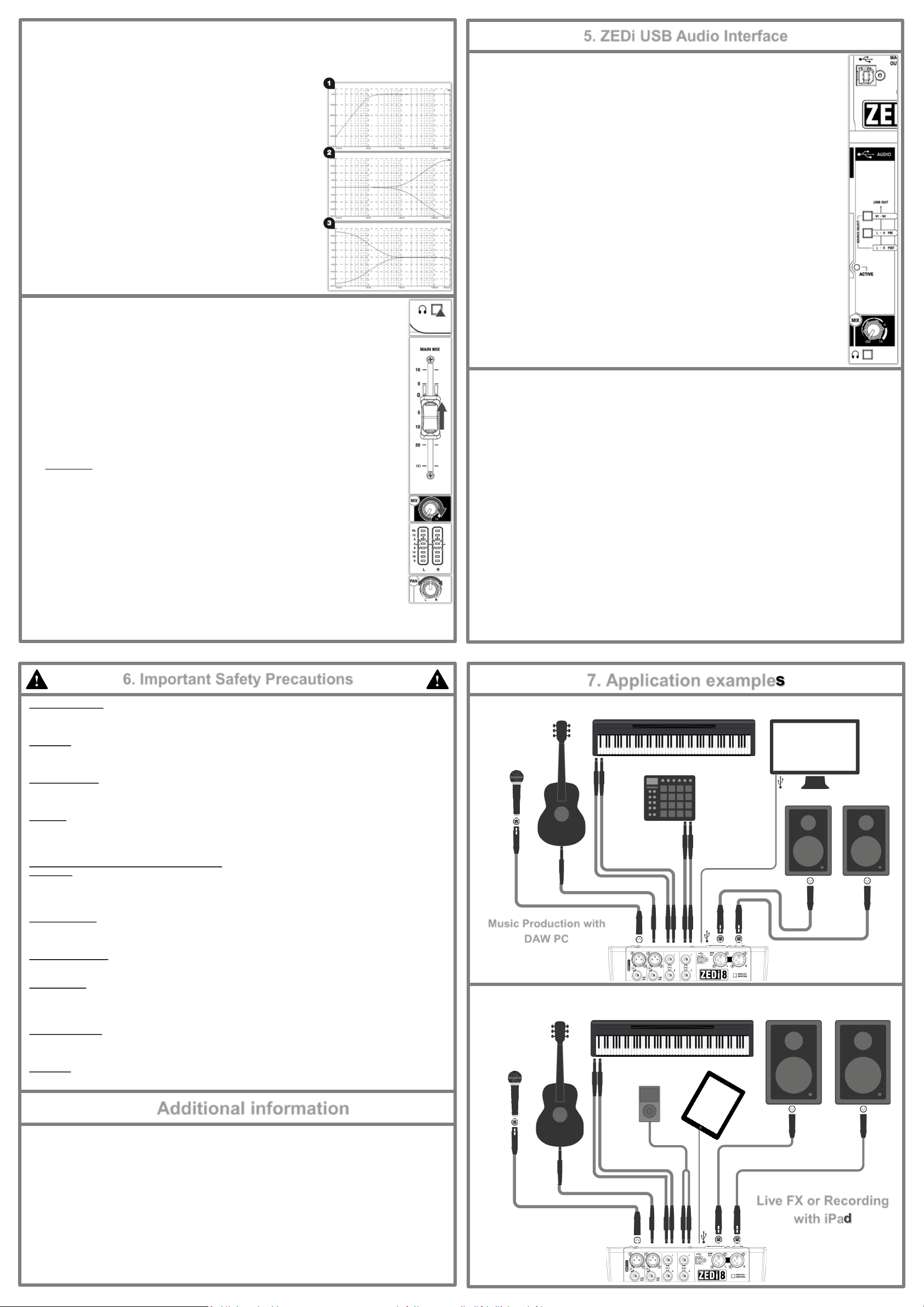
7. Application examples
Water and moisture:
Do not expose the mixer to rain or moisture or use it in damp or wet conditions.
Do not place containers of liquids on it which might spill into any openings.
Ventilation:
Do not obstruct the ventilation slots or position the mixer where the air flow required for ventilation is impeded.
If the mixer is to be placed in a rack unit or flight case ensure that it is well ventilated.
Heat and vibration:
Do not place the mixer where it is subject to excessive heat or direct sunlight.
Keep the mixer away from any equipment which produces excessive heat or vibration.
Servicing:
Switch off equipment and unplug the power cord immediately if it is exposed to moisture, spilled liquid, objects fallen into
the openings, if the power cord or plug have become damaged, during lightning storms, or if smoke, odour or abnormal
noise is noticed.
Refer servicing to qualified technical personnel only.
Installation:
Install the mixer in accordance with the instructions printed in this User Guide.
Do not connect the output of power amplifiers directly to the mixer.
Only use audio connectors and plugs for their intended purpose.
Read instructions:
Retain these safety and operating instructions for future reference.
Adhere to all warnings printed here and on the mixer and follow the operating instructions printed in this User Guide.
Do not remove cover:
Never operate the mixer if the cover is not correctly fitted.
Power sources:
Only connect the console to mains power of the type described in this User Guide and marked on the rear panel.
Use a power cord with sealed mains plug appropriate for your local mains supply as provided with the mixer.
If the provided plug does not fit into mains your outlet consult your service agent for assistance.
Music Production with
DAW PC
Power cord routing:
Run the power cord so that it is out of the way and not likely to be walked on, stretched or pinched by items placed upon or
against it.
Grounding:
Never remove or tamper with the ground connection or polarity in the power cord.
Additional information
For all additional information such as hardware specification, product information or technical support please go to
A limited one year manufacturer’s warranty applies to this product, the conditions of the warranty can be found at
For service or support in your local area please go to
http://www.allen-heath.com/where-to-buy and search f or the count ry you are in.
Please register this product at http://www.allen-heath.com/register t o r ecei ve useful i nf ormation fr om tim e to time.
Allen & Heath Limited, Kernick Industrial Estate, Penryn, Cornwall, TR10 9LU, UK
Copyright © 2015 Allen & Heath Limited. All rights reserved.
http://www.allen-heath.com
http://www.allen-heath.com/legal
ZEDi-8 User Guide AP10073 Issue 2
Live FX or Recording
with iPad
 Loading...