

Page 1

ALLEN&HEATH
WARNING – HIGH VOLTAGES
Power Supply Unit (PSU) work should only
be carried out by qualified personnel.
We recommend that you use an approved Allen & Heath
service centre for all power supply work.
Please contact your local Allen & Heath distributor for more details.
http://www.allen-heath.com/
Page 2

SERVICE INFORMATION
Publication AP6047
Page 3

Introduction
This publication provides technical information on servicing the Allen & Heath XONE VF-1 Analogue Filter
unit. Included are internal layout drawings, block diagrams and circuit schematics with board layouts.
Whilst we believe this information to be reliable we do not assume responsibility for inaccuracies. We also
reserve the right to make changes in the interest of further product development.
Additional Resources
Allen & Heath web site www.allen-heath.com Product information
Technical downloads
Distribution contacts
Company contacts
Technical support support@allen-heath.com
See web for local contact
XONE VF-1 user guide AP5917 Operating instructions
Performance specification
XONE VF-1 Service Information
Issue status: xonevf-1_ap6047_1.doc
Print date: 07 December 2004
Copyright © 2004 Allen & Heath. All rights reserved
Manufactured in the United Kingdom by Allen & Heath
Kernick Industrial Estate, Penryn, Cornwall, TR10 9LU, UK
http://www.allen-heath.com
2 xonevf-1_ap6047_1.doc
Page 4

Servicing Precautions – General Notes
Service personnel: Service work should be carried out by technically qualified service personnel only.
Mains power is dangerous and can kill. Do not attempt to work on a linear or switched
mode power supply if you are not suitably qualified to do so. Do not attempt to repair
surface mount circuit assemblies unless you are suitably qualified and have the
necessary facilities to do so. Replacement circuit assemblies can be ordered.
Service facilities: Ensure a suitably sized work surface is available. Ensure this is clear of dirt, debris
and obstructions which may damage the equipment surfaces. Ensure adequate
lighting. Use the correct tools for the job and ensure they are in good working order.
Ensure all workshop safety requirements are adhered to.
Service information: Check that you have all the information you need before starting the service job. Refer
to the Allen & Heath web site or contact Allen & Heath technical support for details on
the latest information. Full technical information can be downloaded from the web site
Distributor Zone (password required).
Mains power: Connect the equipment to mains power only of the type described in the user guide
and marked on the rear panel. The power source must provide a good ground
connection. Ensure you always use an isolation transformer when working on any
mains power supply unit.
Mains cord and fuse: Use the correct power cord as supplied with the equipment. Do not remove or tamper
with the ground connection in the power cord. Heed the Important Mains Plug Wiring
Instructions printed in the user guide if it is necessary to rewire the mains cord.
Always replace the equipment mains fuse with the correct type and rating as
described in the user guide and marked on the equipment panel.
Opening the unit: Switch off and remove the mains power cord before opening the equipment. Ensure
all power supply covers and safety shields are in place before applying power with the
unit open for diagnostic fault finding.
Closing the unit: Before finishing, check the quality and accuracy of the service work carried out.
Remove any dirt or debris as this may cause equipment failure in the future. Ensure all
assemblies, harnesses and connectors are correctly aligned and plugged in. Ensure
that jumper settings and control configurations are correctly set according to the
requirements of the customer.
Testing the unit: Before operating the equipment, read and adhere to the Important Safety Instructions
printed in the user guide. Test that the service work has been successfully carried out.
Shipping the unit: Use adequate packing such as the original packaging or purpose designed flight case
if you need to ship the unit. To avoid injury to yourself or damage to the equipment
take care when lifting, moving or carrying the equipment.
Servicing Notes – XONE VF-1
User maintenance: There are no user serviceable parts inside. Refer any service work to competent
technical personnel only.
Technology: The XONE VF-1 uses SMT (surface mount) PCB technology. In certain cases it may
be better to replace a faulty assembly rather than try to fix it without the appropriate
tools and training. The power supply is a built-in universal mains input, switched
mode circuit which should be serviced by suitably qualified personnel only.
Operation: The XONE VF-1 is an analogue filter unit. To ensure optimum performance and
reliability it should be connected and operated as described in the user guide.
Fault finding: Refer to the system block diagram and circuit drawings to follow through the signal
path during fault diagnosis. Replace suspected faulty components only with those
specified by Allen & Heath. The use of lower grade alternatives may degrade the
performance.
xonevf-1_ap6047_1.doc
3
Page 5

Contents Log
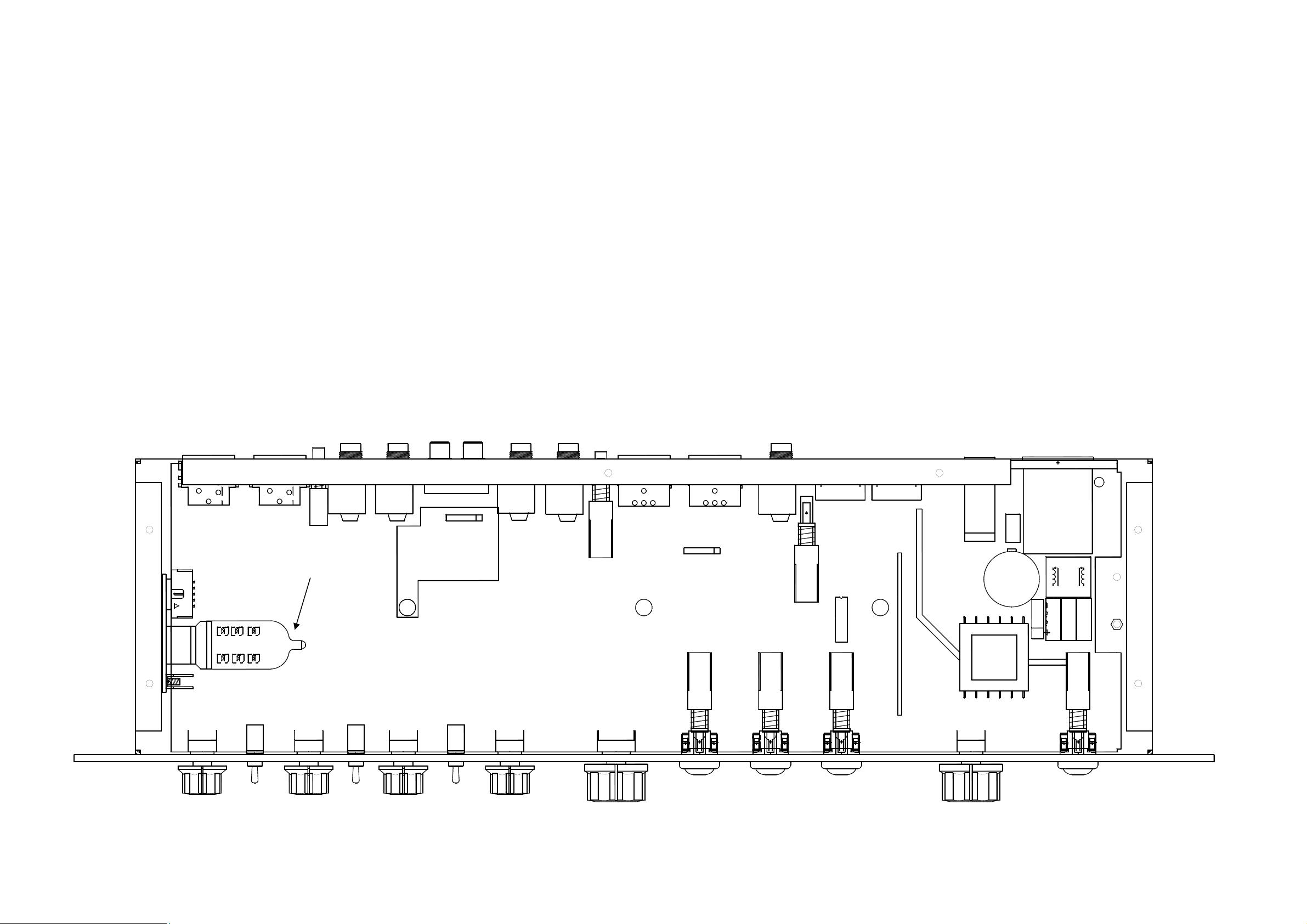
Internal Layout Drawing .............................................xonevf-1_layout_1.pdf
Surface and Main Parts................................................xonevf-1_parts_1.pdf
System Block Diagram ................................. xonevf-1_blockdiagram_1.pdf
Main PCB Assembly iss.1 .............................xonevf-1_003-358_main_1.pdf
Main PCB Assembly iss.4 .............................xonevf-1_003-358_main_4.pdf
RIAA Option PCB ............................................ xonevf-1_003-360_riaa_a.pdf
RIAA Option Fitting Instructions ......................... xonevf-1_riaa_fitting_1.pdf
4 xonevf-1_ap6047_1.doc
Page 6
Product .........................XONE:VF-1/120
.....................................XONE:VF-1/220
.....................................XONE:VF-1/240
.................................. XONE:VF-1R/120
.................................. XONE:VF-1R/220
.................................. XONE:VF-1R/240
Main Assembly ......................... 003-357
PCB Assembly ......................... 003-358
Pack Assembly......................... 003-359
RIAA Option PCB Assy ............ 003-360
Valve ECC82 ............................AE5139
21
3
CN12
CN16
12
3
CN7CN8 CN9
SW10
CN2CN3 CN4
CN1
AB
CN1
1
CN5
G
123
SW1
RIAA OPTION
VALVE ECC82 AE5139
LD1LD2LD3
LD4LD5LD6
FH1 FH2
-
PCB ASSY
003-358
G
CN10
321
CN6
CN17
1
SW5
PIC SKT
CN13CN14
WARNING HIGH VOLTAGE!
SW8
SW7
SW9
F1
NTC1
TX1
CN15
LN
L1
C117
BR1
R207
P1
C113C114 C115
SW6
SW2
VR1 VR2
LD8
SW4
VR3
SW3
VR4 VR6
VR5
LD9
LD12
LP4
LD11
LD7
LD10
LD13
LD14
LP1 LP2 LP3
xone_vf-1_layout_1.doc Sheet 1 of 1
Page 7

R15
003-358 iss.1
R64
R65
R60
R61
U4A
2
3
6
5
2
3
6
5
10K 1%
U3A
R16
R17
10K 1%
U3B
R23
10K 1%
R6
10K 1%
U2A
R7
10K 1%
R8
10K 1%
U2B
R9
10K 1%
TL072D
R24
3K9
C5
15P
C43
100P_S
TL072D
10K 1%
C44
100P_S
C45
100P_S
C46
100P_S
C39
100P_S
TL072D
C40
100P_S
C41
100P_S
C42
100P_S
1
TL072D
1
7
TL072D
C19
47/25
1
7
100N
R68
47R
R69
47R
R66
47R
R67
47R
C36
R45
47K
R1
10K 1%
6
5
R4
10K 1%
2
3
R13
10K 1%
R5
10K 1%
U1B
TL072D
R14
10K 1%
U1A
TL072D
C2
15P
C4
15P
PRE_OUT_L
7
1
C30
100N
C9
47/25
OFF_CTRL
PRE_OUT_R
SW10B
4
6
R39
47K
R226
10K
C14
5
47/25
C141
22N
100N
MMBFJ111
R22710K
C33
R42
47K
Q11
FILT_OUT_L
R230
10K
10K
OFF_CTRL
C133
47/25
R220
47K
Q13
MMBFJ111
R231
FILT_OUT_R
C31
100N
C10
47/25
6
5
R223
47K
U29B
C136
47/25
R41
10K 1%
C11
15P
TL072D
R40
47K
ON_CTRL
C34
100N
C15
47/25
R228
10K
2
3
7
C139
100N
R229
10K
R216
10K 1%
U29A
R221
47K
C134
47/25
C142
22N
C32
15P
TL072D
R232
10K
R43
47K
R44
10K 1%
Q12
MMBFJ111
1
C140
100N
R233
10K
R224
47K
C137
47/25
C135
47/25
R222
47K
MMBFJ111
CN2
R
T
e
CN1A
A
W
OUT_LEFT
R
CN3
d
B
W
OUT_RIGHT
R
CN1B
CN7
1 2
R
T
CN8
1 2
R2
12K 1%
R32
20K 1%
R3
12K 1%
3
XLR NC3FAH20
0
R10
10K 1%
R11
12K 1%
R34
R12
12K 1%
3
XLR NC3FAH20
0
R33
20K 1%
20K 1%
R35
20K 1%
C1
15P
C3
15P
6
5
R217
10K 1%
Q14
OUT_LEFT
R215
10K 1%
C16
15P
U30B
TL072D
OUT_RIGHT
C138
47/25
R225
47K
R50
47R 1%
7
R51
47R 1%
R218
10K 1%
C35
2
3
15P
U30A
TL072D
1
3
1
LEFT
SW10A
RIGHT
R63
4K71%
4K71%
2
4K71%
R62
4K71%
R59
4K71%
4K71%
4K71%
R58
4K71%
c
ON_CTRL
SW1A
PRE_OUT_L
FILT_OUT_L
R18
10K 1%
R19
10K 1%
1
3
2
R234
100K 1%
3
2
R22
15K 1%
C12
47/25
R72
2K2 1%
R73
2K2 1%
C13
47/25
C49
100N
C17
47/25
R70
2K2 1%
R71
2K2 1%
C18
47/25
C50
100N
C47
100N
C48
100N
L_OUT_-
R75
100K 1%
R76
100K 1%
L_OUT_+
R_OUT_-
R77
100K 1%
R78
100K 1%
R_OUT_+
R52
47R 1%
R53
47R 1%
LIP
LEFT JACK OUT
3
0
LEFT BALANCED OUT
3
0
RIGHT BALANCED OUT
T
R
CN9
XLR NC3MAH20
12
CN10
XLR NC3MAH20
12
CN4
b
+15V
-15V
R84
10R PF RAD
R83
10R PF RAD
a
ALLEN&HEATH
Kernick Industrial Estate,
Penryn, Cornwall,
England. TR10 9LU
+44 (0)8707 556250
Tel:
+44 (0)8707 556251
Fax:
ABCDEFGH
C55
100/25
C54
100/25
8
U1C
V+
V-
TL072D
4
ISSUE BY DATE
1 ARJ 30-07-04
8
V+
V-
TL072D
4
SW1B
4
PRE_OUT_R
FILT_OUT_R
8
V+
V-
TL072D
4
+VIO
U29C
-VIO
8
V+
V-
4
U30C
TL072D
+VIO
U2C
CHK
BY
8
U3C
V+
V-
TL072D
4
-VIO
FILE: AG5877_1 SHEET 1.Sch 14:45:17 4-Nov-2004
8
V+
V-
4
U4C
TL072D
R20
10K 1%
R21
10K 1%
6
5
R235
100K 1%
PRINTED:
5
6
R26
15K 1%
U4B
TL072D
R25
3K9 0805
C6
15P
7
FILT_OUT_L
FILT_OUT_R
RIGHT JACK OUT
MONITOR OUT
100N
C20
47/25
C37
TITLE:
R54
47R 1%
R55
47R 1%
R46
47K
C21
47/25
C22
47/25
R56
47R 1%
R57
47R 1%
XONE VF-1 MAIN PCB
PAGE:
DRG No: ISSUE: SHEET: OF
C5877 1 5
1
CN5
T
R
CN6
T
R
Page 8

e
003-358 iss.1
d
c
b
FILT_IN_L
FILT_IN_R
R211
10K 1%
R212
10K 1%
C23
47/25
R93
47K
R29
10K 1%
C24
47/25
R94
47K
R30
10K 1%
R96
10K
R97
10K
2
U5A
3
TL072D SMD
R95
10K 1%
25
3
VR5B
20KK
R118
1K8
R121
R104
10K
R105
10K
6
U5B
5
TL072D SMD
R31
10K 1%
16
4
VR5A
20KK
R119
1K8
R122
U22B
NSL32
NSL32
39K
U23B
NSL32
1
7
NSL32
U23A
39K
U22A
C62
10/16
10/16
C63
R124
1K0 1%
R125
1K0 1%
D17
LL4148
D18
LL4148
12
JP2
ARC DISABLE
FILT_OUT_L
ARC DISABLE
1 2
JP3
JUMP 2 STRT
FILT_OUT_R
C64
C65
C66
C67
470P
470P
470P
470P
R130
R138
R131
R139
R132
R140
R133
R141
470R
30K1%
470R
30K1%
470R
30K1%
470R
30K1%
-VF
+15V
-15V
VCF_DC
3
2
6
7
11
10
14
15
9
8
R86
10R PF RAD
R85
10R PF RAD
U9
VCA1
VCA2
VCA3
VCA4
VGND
SSM2164S_1(16)
+VF
MD
V+
4
5
12
13
1
16
C57
100/25
C56
100/25
8
V+
V-
4
2
3
6
5
6
5
2
3
U5C
TL072D
C68
1N0 0805
U6A
TL072D SMD
C69
1N0 0805
U6B
TL072D SMD
C70
1N0 0805
U7B
TL072D SMD
C71
1N0 0805
U7A
TL072D SMD
8
U6C
V+
V-
TL072D
4
1
7
7
1
8
U7C
V+
V-
TL072D
4
C72
10/50
C73
10/50
C74
10/50
C75
10/50
C76
10/50
C77
10/50
+VF
-VF
R98
10K
R99
10K
R100
10K
R106
10K
R107
10K
R108
10K
8
V+
V-
4
U8C
TL072D
R101
10K
R102
10K
R103
10K
R109
10K
R110
10K
R111
10K
Q1
Q2
Q3
Q5
Q4
Q6
MMBFJ111
MMBFJ111
MMBFJ111
MMBFJ111
MMBFJ111
MMBFJ111
HP_DC_CNTRL
BP_DC_CNTRL
LP_DC_CNTRL
LP_DC_CNTRL
BP_DC_CNTRL
HP_DC_CNTRL
C7
15P
R142
10K1%
2
U8A
3
6
U8B
5
TL072D
C8
15P
R143
10K1%
TL072D
1
7
FILT_OUT_L
FILT_OUT_R
a
ALLEN&HEATH
Kernick Industrial Estate,
Penryn, Cornwall,
England. TR10 9LU
+44 (0)8707 556250
Tel:
+44 (0)8707 556251
Fax:
ABCDEFGH
ISSUE BY DATE
1 ARJ 30-07-04
CHK
BY
VR5C
BRKT
8
9
20KK
FILE: AG5877_1 SHEET 2.Sch 14:45:18 4-Nov-2004
PRINTED:
TITLE:
XONE VF-1 MAIN PCB
PAGE:
DRG No: ISSUE: SHEET: OF
C5877 2 5
1
Page 9

PRE_OUT_L
003-358 iss.1
PRE_OUT_R
R144
68K 1%
R145
68K 1%
e
d
c
1
3
5
7
9
1
3
5
7
9
2
4
6
8
10
2
4
6
8
10
b
a
ALLEN&HEATH
Kernick Industrial Estate,
Penryn, Cornwall,
England. TR10 9LU
+44 (0)8707 556250
Tel:
+44 (0)8707 556251
Fax:
ABCDEFGH
R47
47K
C25
47/25
R126
1K0 1%
+VS
2
3
VHT
GRID_L
CATH_L
CN11
IDC 5X2 F STRT
-15V_VPCB
GRID _R
CATH_R
HEATER
R79
100K 1%
D2
LL4148
2
U10A
3
D1
LL4148
C81
330N
C82
330N
U13A
TL072D
R168
1M0 1%
R169
1M0 1%
ISSUE BY DATE
1 ARJ 30-07-04
+5V
2
1
7
R171
TL072D
3
R170
4K7 1%
8
4K7 1%
R49
47K
1
4
FREQUENCY
20KK
D5
LL4148
D6
LL4148
C38
100N
R180
30K 1%
C26
47/25
C27
47/25
R184
30K 1%
BRKT
13
VR6A
VR1A
2
EF FOLLOWER
20KK
1 3
R165
30K 1%
R166
30K 1%
4
SW4B
2
1
3
MIDI_Fc
Fc_SND
EF_LEVEL
R150
120K 1%
LFO DEPTH
VR4A
20KK
1 3
6
U15B
5
TL072D
2
U16A
3
TL072D
SW5A
2
C98
PRINTED:
R152
2
9K1
R151
6K8 1%
R164
30K 1%
C103 22P_S
7
C104
R186
R190
680P
C105
R187
R181
680P
C106
R188
R182
680P
C107
R189
680P
22P
1
VD_R
VD_L
560R 1%
+5V
EVELOPE FOLLOWER SIDE-CHAIN
1
R48
47K
LFO
EF_LEVEL
V1A
ECC82
69
V1B
ECC82
5
CHK
BY
D3
LL4148
5
6
R160
220R
D4
LL4148
LFO SPEED
VR3A
2
20KK
1 3
R80
100K 1%
U13B
TL072D
EF TO OVERDRIVE
R162
47K
VD_L
BRKT
5
6
VR1B
FILE: AG5877_1 SHEET 3.Sch 14:45:18 4-Nov-2004
R127
1K0 1%
7
R
SW4A
2
L
+5V
VR2A
2
20KK
1 3
OVERDRIVE DEPTH
C83
R173
33K 1%
330N
C99
10N
+15V
-15V
5
BRKT
R90
10R PF RAD
R89
10R PF RAD
6
VR2B
R163
15K
C85
1/63
1
3
R179
56K 1%
LD1
LD2
LD3
VO_L
VALVE_HT
BRKT
5
R146
330K 1%
C86
1/63
100/25
6
VR3B
C61
C60
100/25
R147
1M2 1%
1
3
WAVEFORM
1
3
2
3
RD
RD
RD
CN12
BRKT
5
R
L
R
L
SW3A
R155
10K1%
10N
U14A
TL072D
112
334
556
778
9910
8
4
6
VR4B
SW2A
C93
U14C
V+
V-
TL072D
R148
220K
2
2
RD
RD
RD
DECAY
1
2
4
6
8
10
BRKT
5
+5V
R159
10K1%
LD4
LD5
LD6
VO_R
-VO
+10V
C88
47N
10K1%
8
V+
V-
TL072D
4
6
VR6B
R149
220K
R156
LL4148
U15C
D20
6
5
C84
330N
+VO
-VO
LL4148
U14B
TL072D
5
C89
47N
2
3
D21
R157
10K1%
10N
R174
33K 1%
C100
10N
8
4
BRKT
R158
10K1%
D22
LL4148
C94
U16C
V+
V-
TL072D
4
SW2B
U11A
7
VD_R
5
6
C92
TL072D
10N
5
U10B
TL072D
1
R120
470R
LL4148
BRKT
7
HP_DC
BP_DC
-5
VALVE OVERDRIVE CIRCUIT
CV_1
CV_2
D19
PRE_OUT_L
VO_L
VO_R
PRE_OUT_R
4
5
SW3B
D7
LL4148
2
3
R183
30K 1%
560R 1%
27K 1%
560R 1%
27K 1%
560R 1%
30K 1%
6
5
R36
20K 1%
U12A
R153
10K1%
C91
10N
TL072D
U12B
1
3
2
6
7
11
10
14
15
9
8
10R PF RAD
10R PF RAD
7
5
6
10K1%
R88
R87
U17
VCA1
VCA2
VCA3
VCA4
VGND
SSM2164S_1(16)
U11B
R37
20K 1%
C95
NF
7
TL072D
C90
NF
TL072D
+15V
-15V
-VO +VO
R154
-VS
R123
39K
C101
10N
MD
V+
C102
10N
TITLE:
R167
2K7
C59
100/25
C58
100/25
R175
33K 1%
4
5
12
13
1
16
R178
33K 1%
XONE VF-1 MAIN PCB
8
V+
V-
4
R185
VCF_DC
U10C
TL072D
2
3
30K 1%
C96
R176
33K 1%
U15A
TL072D
22P
8
V+
V-
TL072D
4
6
5
U11C
1
R177
C97
U16B
TL072D
+VS
-VS
33K 1%
22P
8
U12C
V+
V-
TL072D
4
FILT_IN_L
7
PAGE:
DRG No: ISSUE: SHEET: OF
C5877 3 5
1
8
4
-5
FILT_IN_R
U13C
V+
V-
TL072D
Page 10

C118
003-358 iss.1
100NMLC
+5V
R112
SW6B
5
4
6
e
SW7B
SW8B
SW9B
4
6
4
6
4
6
5
5
d
5
SW6A
2
FILTER ON
SW7A
2
HIGH PASS
SW8A
2
BAND PASS
SW9A
2
LOW PASS
10K
1
3
+5V
R113
10K
1
3
1
3
1
3
R114
10K
Fc_SND
R115
10K
C143
4N7
10
RC0/AN4
9
RC1/AN5
8
RC2/AN6
7
RC3/AN7
6
TX
5
RX
+5V
1
VDD
VSS
14
U18
RA0/AN0
RA1/AN1
RA2/AN2
RA3
RA4/AN3
RA5
PIC16F688
CN17
6
13
12
11
4
3
2
12345
+5V
LD7GNLD10
C87
GN
GN
GN
1/63
R134
470R
R135
470R
R136
470R
R137
470R
R116
10K
MIDI_Fc
HP_DC
BP_DC
LP_DC
FILT_ON
+5V
R191
4K7 1%
R192
4K7 1%
5
4
9
8
11
10
7
6
U20A
LM2901 SMD
U20C
LM2901 SMD
U20D
LM2901 SMD
U20B
LM2901 SMD
R81
100K 1%
R74
3K9
R193
4K7 1%
2
14
13
1
R196
1M0 1%
R194
4K7 1%
R197
1M0 1%
R195
4K7 1%
R198
1M0 1%
R237
4K7 1%
R238
4K7 1%
Q9
BC848B
-VMID
R236
1M0 1%
D23
LL4148
R201
1M0 1%
D8
LL4148
HP_DC_CNTRL
C108
22N
BP_DC_CNTRL
C109
22N
LP_DC_CNTRL
C110
22N
ON_CTRL
R239
220K
OFF_CTRL
R202
220K
R219
10K 1%
8
1
R241
10R
FILT_ON
CR
2
C111
4N7
LP_DC
BP_DC
HP_DC
7
3
R199
82K
LD8GNLD11
LD9GNLD12
LD13
BL
LD14
BL
6
4 5
R200
680K 2%
+VMID
U19
LM2907
c
+15V
-15V
b
a
ALLEN&HEATH
Kernick Industrial Estate,
Penryn, Cornwall,
England. TR10 9LU
+44 (0)8707 556250
Tel:
+44 (0)8707 556251
Fax:
ABCDEFGH
R92
10R PF RAD
R91
10R PF RAD
ISSUE BY DATE
1 ARJ 30-07-04
C28
47/25
C29
47/25
3
V+
V-
12
Fc_SND
+VMID
U20E
LM2901 SMD
-VMID
R240
9K1
CHK
BY
+5V
R128
1K0 1%
Q8
R117
10K
VCC
BASE
COLL
GND
U21
6N138
NC
NC
A
K
R172
+5V
+5V
8
7
6
5
LOCAL OFF
SW5B
5
FILE: AG5877_1 SHEET 4.Sch 14:45:19 4-Nov-2004
5K6
4
6
R203
1K2 1%
Q7
BC848B
1
2
3
4
BC848B
R161
220R
D9
LL4148
R27
220R
3
1
0
0
425
CN13
1
425
CN14
3
R28
MIDI OUT
220R
MIDI IN
PRINTED:
TITLE:
XONE VF-1 MAIN PCB
PAGE:
DRG No: ISSUE: SHEET: OF
C5877 4 5
1
Page 11

CN15
003-358 iss.1
N
L
E
LP1 LP2 LP3 LP4 FID1 FID2AI4AI1 AI2
FH4
CN16
123
FID3 FID4
4
INLET
FILTERED IEC
MAINS
NTC1
INRUSH SUPP NTC20R
F1
12
AI3
EMC SCREEN
FH1 FH2 FH3
e
T500mA
E
N
2
P1
PIN
d
c
b
L
3
1
3
C113
L1
100N 275V
1
C78
CHOKE 20MH
100N 100V/MLC
10/50
L_GND
L2
4.7uH
R204
6K8 1%
C112
4N7
2 4
C120
1
8
6
L_GND
COMP
VREF
OUT
C121
150P
R205
7
VCC
GND
5
L_GND
23
BR1
150K 1%
U24
ISEN
VFB
RT/CT
UC3842D1
FUSE HOLDER 20MM
2KBP206
3
2
4
C114
100N 275V
14
C115
100N 275V
L_GND
R38
20K 1%
R206
3K3 1%
C117
L_GND
C51
100N
L_GND
68/400
L_GND
C132
330P
C127
2N2 250V/PEM
R207
82K 1W
D10
C122
120/63 LESR
R208
68R
L_GND
R129
1K0 1%
BYG80G
R82
100K 1%
R209
1R0 1W
C116
100N 275V
D15
P6KE200A
D16
BYV26E
Q10
STB4NC80ZT4
R210
1R0 1W
L_GND L_GND
TX1
1
PRIMARYBIAS
2
3
5 8
XFRMR E/30/15/7A (UNI) (AM5547)
12
10
7
11
9
D11
BYG80G
D13
BYG80G
BYG80G
D14
D12
BYG80G
C129
470/25 LESR
C128 470/25 LESR
C123
120/63 LESR
GND_PSU
C125
120/63 LESR
GND_PSU
L3
L4
L5
L6
4.7uH
4.7uH
4.7uH
4.7uH
4.7uH
U25
1
2
C79
10/50
3
Vin
2
1
Vin
U27
1
Vin
U28
Vin
C131
470/25 LESR
C130
470/25 LESR
C124
120/63 LESR
L7
C126
120/63 LESR
+15V
GND
7815
U26
-15V
GND
+5V
GND
7805
2
ADJ
TL783
1
Vout
7915
3
3
3
C52
100N
C53
100N
2
+15V
C144
10/50
-15V
+10V
+5V
C80
10/50
VALVE_HT
R213
1K0 1%
R214
39K 1%
C119
47/63
a
ALLEN&HEATH
Kernick Industrial Estate,
Penryn, Cornwall,
England. TR10 9LU
+44 (0)8707 556250
Tel:
+44 (0)8707 556251
Fax:
ABCDEFGH
ISSUE BY DATE
1 ARJ 30-07-04
CHK
BY
FILE: AG5877_1 SHEET 5.Sch 14:45:19 4-Nov-2004
PRINTED:
TITLE:
XONE VF-1 MAIN PCB
PAGE:
DRG No: ISSUE: SHEET: OF
C5877 5 5
1
Page 12

003-358 iss.1
Page 13

e
003-358 iss.4
d
B
c
CN1A
A
LH_RCA_OUT
CN2
LH_RCA_IN
W
OUT_LEFT
R
RH_RCA_OUT
CN3
RH_RCA_IN
W
OUT_RIGHT
R
CN1B
R
T
R
T
C134
R1
10/50
R2
R32
20K 1%
R3
10K 1%
3
CN7
1 2
XLR NC3FAH20
0
C135
CN8
1 2
R10
10/50
R11
R34
R12
10K 1%
3
XLR NC3FAH20
0
10K 1%
10K 1%
10K 1%
10K 1%
20K 1%
R33
20K 1%
R35
20K 1%
R5
10K 1%
C2
CN18
U1B
TL072D
1
2
3
4
5
6
U1A
TL072D
15P
LH_RCA_OUT
LH_RCA_IN
+15V
-15V
RH_RCA_IN
RH_RCA_OUT
R14
10K 1%
C4
15P
6
5
C1
R4
10K 1%
15P
RIAA OPTION CONNECTOR
2
3
C3
R13
10K 1%
15P
PRE_OUT_L
7
1
C30
100N
C9
100/35
PRE_OUT_R
4
6
R39
47K
OFF_CTRL
SW10B
R226
10K
C141
22N
100N
C14
5
100/35
MMBFJ111
R22710K
C33
R42
47K
Q11
R220
47K
FILT_OUT_L
R230
10K
10K
OFF_CTRL
C133
330/10
C31
100N
C10
100/35
Q13
MMBFJ111
R231
R223
47K
FILT_OUT_R
R15
10K 1%
C43
2
R22
10K 1%
R18
10K 1%
R63
4K71%
4K71%
4K71%
R62
4K71%
R59
4K71%
4K71%
4K71%
R58
4K71%
R234
10K 1%
R64
R65
2
3
R60
R61
6
5
3
U4A
2
OUT_LEFT
R41
10K 1%
C11
U29B
C136
330/10
15P
TL072D
R228
10K
R40
47K
ON_CTRL
C34
100N
C15
100/35
C142
22N
C32
15P
TL072D
R232
10K
R43
47K
R44
10K 1%
Q12
MMBFJ111
1
R233
10K
ON_CTRL
Q14
MMBFJ111
R217
10K 1%
7
R229
10K
R216
10K 1%
2
U29A
3
6
5
6
5
R215
10K 1%
C16
15P
U30B
TL072D
OUT_RIGHT
PRE_OUT_L
R50
47R 1%
7
R51
47R 1%
R218
10K 1%
C35
2
3
15P
U30A
TL072D
LEFT
SW10A
1
3
RIGHT
1
SW1A
1
3
2
2
3
6
5
U3A
R16
R17
10K 1%
U3B
R23
10K 1%
R6
10K 1%
U2A
R7
10K 1%
R8
10K 1%
U2B
R9
10K 1%
TL072D
R24
10K 1%
C5
15P
100P_S
TL072D
10K 1%
C44
100P_S
C45
100P_S
C46
100P_S
C39
100P_S
TL072D
C40
100P_S
C41
100P_S
C42
100P_S
1
TL072D
1
7
TL072D
C19
47/25
1
7
100N
R68
47R
R69
47R
R66
47R
R67
47R
C36
R45
47K
C12
47/25
R72
2K2 1%
R73
2K2 1%
C13
47/25
C49
100N
C17
47/25
R70
2K2 1%
R71
2K2 1%
C18
47/25
C50
100N
C47
100N
C48
100N
L_OUT_-
R75
100K 1%
R76
100K 1%
L_OUT_+
R_OUT_-
R77
100K 1%
R78
100K 1%
R_OUT_+
R52
47R 1%
R53
47R 1%
LIP
LEFT JACK OUT
3
0
LEFT BALANCED OUT
3
0
RIGHT BALANCED OUT
T
R
CN9
XLR NC3MAH20
12
CN10
XLR NC3MAH20
12
CN4
b
+15V
-15V
R84
10R PF RAD
R83
10R PF RAD
a
ALLEN&HEATH
Kernick Industrial Estate,
Penryn, Cornwall,
England. TR10 9LU
+44 (0)8707 556250
Tel:
+44 (0)8707 556251
Fax:
ABCDEFGH
C55
100/25
C54
100/25
8
U1C
V+
V-
TL072D
4
ISSUE BY DATE
1 ARJ 30-07-04
2 ARJ 17-08-04
8
V+
V-
TL072D
4
R21
10K 1%
SW1B
4
PRE_OUT_R
8
V+
V-
TL072D
4
+VIO
U29C
-VIO
8
V+
V-
4
U30C
TL072D
+VIO
U2C
CHK
BY
8
U3C
V+
V-
TL072D
4
-VIO
FILE: AG5877_4 SHEET 1.Sch 11:50:14 2-Nov-2004
8
V+
V-
4
U4C
TL072D
6
PRINTED:
R20
5
10K 1%
R235
10K 1%
5
6
U4B
TL072D
R25
10K 1%
C6
15P
7
FILT_OUT_L
FILT_OUT_R
RIGHT JACK OUT
MONITOR OUT
100N
C20
47/25
C37
TITLE:
R54
47R 1%
R55
47R 1%
R46
47K
C21
47/25
C22
47/25
R56
47R 1%
R57
47R 1%
XONE VF-1 MAIN PCB
PAGE:
DRG No: ISSUE: SHEET: OF
C5877 1 5
4
CN5
T
R
CN6
T
R
Page 14

e
003-358 iss.4
d
c
b
FILT_IN_L
FILT_IN_R
R211
10K 1%
R212
10K 1%
C23
330/10
R93
47K
R29
10K 1%
C24
330/10
R94
47K
R30
10K 1%
R96
10K
R97
10K
2
U5A
3
TL072D SMD
R95
10K 1%
25
3
VR5B
20KK
R118
1K8
R121
R104
10K
R105
10K
6
U5B
5
TL072D SMD
R31
10K 1%
16
4
VR5A
20KK
R119
1K8
R122
U22B
NSL32
NSL32
39K
U23B
NSL32
1
7
NSL32
U23A
39K
U22A
C62
10/16
10/16
C63
R124
1K0 1%
R125
1K0 1%
D17
LL4148
D18
LL4148
12
JP2
ARC DISABLE
FILT_OUT_L
ARC DISABLE
1 2
JP3
JUMP 2 STRT
FILT_OUT_R
C64
C65
C66
C67
470P
470P
470P
470P
R130
R138
R131
R139
R132
R140
R133
R141
470R
30K1%
470R
30K1%
470R
30K1%
470R
30K1%
-VF
+15V
-15V
VCF_DC
3
2
6
7
11
10
14
15
9
8
R86
10R PF RAD
R85
10R PF RAD
U9
VCA1
VCA2
VCA3
VCA4
VGND
SSM2164S_1(16)
+VF
MD
V+
4
5
12
13
1
16
C57
100/25
C56
100/25
8
V+
V-
4
2
3
6
5
6
5
2
3
U5C
TL072D
C68
1N0 0805
U6A
TL072D SMD
C69
1N0 0805
U6B
TL072D SMD
C70
1N0 0805
U7B
TL072D SMD
C71
1N0 0805
U7A
TL072D SMD
8
U6C
V+
V-
TL072D
4
1
7
7
1
8
U7C
V+
V-
TL072D
4
C72
47/25
C73
47/25
C74
47/25
C75
47/25
C76
47/25
C77
47/25
+VF
-VF
R98
10K
R99
10K
R100
10K
R106
10K
R107
10K
R108
10K
8
V+
V-
4
U8C
TL072D
R101
10K
R102
10K
R103
10K
R109
10K
R110
10K
R111
10K
Q1
Q2
Q3
Q5
Q4
Q6
MMBFJ111
MMBFJ111
MMBFJ111
MMBFJ111
MMBFJ111
MMBFJ111
HP_DC_CNTRL
BP_DC_CNTRL
LP_DC_CNTRL
LP_DC_CNTRL
BP_DC_CNTRL
HP_DC_CNTRL
C7
15P
R142
10K1%
2
U8A
3
6
U8B
5
TL072D
C8
15P
R143
10K1%
TL072D
1
7
FILT_OUT_L
FILT_OUT_R
a
ALLEN&HEATH
Kernick Industrial Estate,
Penryn, Cornwall,
England. TR10 9LU
+44 (0)8707 556250
Tel:
+44 (0)8707 556251
Fax:
ABCDEFGH
ISSUE BY DATE
1 ARJ 30-07-04
2 ARJ 17-08-04
CHK
BY
VR5C
BRKT
8
9
20KK
FILE: AG5877_4 SHEET 2.Sch 11:50:14 2-Nov-2004
PRINTED:
TITLE:
XONE VF-1 MAIN PCB
PAGE:
DRG No: ISSUE: SHEET: OF
C5877 2 5
4
Page 15

PRE_OUT_L
003-358 iss.4
PRE_OUT_R
R144
68K 1%
R145
68K 1%
e
d
c
1
3
5
7
9
1
3
5
7
9
2
4
6
8
10
2
4
6
8
10
b
a
ALLEN&HEATH
Kernick Industrial Estate,
Penryn, Cornwall,
England. TR10 9LU
+44 (0)8707 556250
Tel:
+44 (0)8707 556251
Fax:
ABCDEFGH
R47
47K
C25
47/25
R126
1K0 1%
+VS
2
3
VHT
GRID_L
CATH_L
CN11
IDC 5X2 F STRT
-15V_VPCB
GRID _R
CATH_R
HEATER
R79
100K 1%
D2
LL4148
2
U10A
3
D1
LL4148
C81
330N
C82
330N
U13A
TL072D
R168
1M0 1%
R169
1M0 1%
ISSUE BY DATE
1 ARJ 30-07-04
2 ARJ 17-08-04
+5V
2
1
7
R171
TL072D
3
R170
4K7 1%
8
4K7 1%
R49
47K
1
4
FREQUENCY
20KK
D5
LL4148
D6
LL4148
C38
100N
R180
30K 1%
C26
47/25
C27
47/25
R184
30K 1%
BRKT
13
VR6A
VR1A
2
EF FOLLOWER
20KK
1 3
R165
30K 1%
R166
30K 1%
4
SW4B
2
1
3
MIDI_Fc
Fc_SND
EF_LEVEL
R150
120K 1%
LFO DEPTH
VR4A
20KK
1 3
6
U15B
5
TL072D
2
U16A
3
TL072D
SW5A
2
C98
PRINTED:
R152
2
9K1
R151
6K8 1%
R164
30K 1%
C103 22P_S
7
C104
R186
R190
680P
C105
R187
R181
680P
C106
R188
R182
680P
C107
R189
680P
22P
1
VD_R
VD_L
560R 1%
+5V
EVELOPE FOLLOWER SIDE-CHAIN
1
R48
47K
LFO
EF_LEVEL
V1A
ECC82
69
V1B
ECC82
5
CHK
BY
D3
LL4148
5
6
R160
220R
D4
LL4148
LFO SPEED
VR3A
2
20KK
1 3
R80
100K 1%
U13B
TL072D
EF TO OVERDRIVE
R162
47K
VD_L
BRKT
5
6
VR1B
FILE: AG5877_4 SHEET 3.Sch 11:50:14 2-Nov-2004
R127
1K0 1%
7
R
SW4A
2
L
+5V
VR2A
2
20KK
1 3
OVERDRIVE DEPTH
C83
R173
0R0
470N_S
C99
NF
+15V
-15V
5
BRKT
R90
10R PF RAD
R89
10R PF RAD
6
VR2B
R163
15K
C85
1/63
1
3
R179
56K 1%
LD1
LD2
LD3
VO_L
VALVE_HT
BRKT
5
R146
330K 1%
C86
1/63
100/25
6
VR3B
C61
C60
100/25
R147
1M2 1%
1
3
WAVEFORM
1
3
2
3
RD
RD
RD
CN12
BRKT
5
R
L
R
L
SW3A
R155
10K1%
10N
U14A
TL072D
112
334
556
778
9910
8
4
6
VR4B
SW2A
C93
U14C
V+
V-
TL072D
R148
220K
2
2
RD
RD
RD
DECAY
1
2
4
6
8
10
BRKT
5
+5V
R159
10K1%
LD4
LD5
LD6
VO_R
-VO
+10V
C88
47N
10K1%
8
V+
V-
TL072D
4
6
VR6B
R149
220K
R156
LL4148
470N_S
U15C
D20
6
5
C84
+VO
-VO
5
D21
LL4148
R157
10K1%
10N
U14B
TL072D
R174
0R0
8
4
BRKT
C89
47N
10K1%
2
3
C94
C100
NF
U16C
V+
V-
TL072D
4
SW2B
R158
U11A
D22
LL4148
7
VD_R
5
6
C92
TL072D
10N
5
U10B
TL072D
1
R120
470R
LL4148
BRKT
7
HP_DC
BP_DC
-5
VALVE OVERDRIVE CIRCUIT
CV_1
CV_2
D19
PRE_OUT_L
VO_L
VO_R
PRE_OUT_R
4
5
SW3B
D7
LL4148
2
3
R183
30K 1%
560R 1%
27K 1%
560R 1%
27K 1%
560R 1%
30K 1%
6
5
R36
20K 1%
U12A
R153
10K1%
C91
10N
TL072D
U12B
1
3
2
6
7
11
10
14
15
9
8
10R PF RAD
10R PF RAD
7
5
6
10K1%
R88
R87
U17
VCA1
VCA2
VCA3
VCA4
VGND
SSM2164S_1(16)
U11B
R37
20K 1%
C95
NF
7
TL072D
C90
NF
TL072D
+15V
-15V
-VO +VO
R154
-VS
R123
39K
C101
MD
V+
C102
NF
TITLE:
R167
2K7
C59
100/25
C58
100/25
R175
NF
NF
4
5
12
13
1
16
R178
NF
XONE VF-1 MAIN PCB
8
V+
V-
4
R185
VCF_DC
U10C
TL072D
2
3
30K 1%
C96
R176
33K 1%
U15A
TL072D
22P
8
V+
V-
TL072D
4
6
5
U11C
1
R177
C97
U16B
TL072D
+VS
-VS
33K 1%
22P
8
U12C
V+
V-
TL072D
4
FILT_IN_L
7
PAGE:
DRG No: ISSUE: SHEET: OF
C5877 3 5
4
8
4
-5
FILT_IN_R
U13C
V+
V-
TL072D
Page 16

C118
003-358 iss.4
100NMLC
+5V
R112
SW6B
5
4
6
e
SW7B
SW8B
SW9B
4
6
4
6
4
6
5
5
d
5
SW6A
2
FILTER ON
SW7A
2
HIGH PASS
SW8A
2
BAND PASS
SW9A
2
LOW PASS
10K
1
3
+5V
R113
10K
1
3
1
3
1
3
R114
10K
Fc_SND
R115
10K
C143
100N
10
RC0/AN4
9
RC1/AN5
8
RC2/AN6
7
RC3/AN7
6
TX
5
RX
+5V
100NMLC
1
VDD
VSS
14
C145
U18
RA0/AN0
RA1/AN1
RA2/AN2
RA3
RA4/AN3
RA5
PIC16F688
CN17
6
13
12
11
4
3
2
12345
+5V
LD7GNLD10
C87
GN
GN
GN
1/63
R134
470R
R135
470R
R136
470R
R137
470R
R116
10K
MIDI_Fc
HP_DC
BP_DC
LP_DC
FILT_ON
+5V
R191
4K7 1%
R192
4K7 1%
5
4
9
8
11
10
7
6
U20A
LM2901 SMD
U20C
LM2901 SMD
U20D
LM2901 SMD
U20B
LM2901 SMD
R81
100K 1%
R74
3K9
R193
4K7 1%
2
14
13
1
R196
1M0 1%
R194
4K7 1%
R197
1M0 1%
R195
4K7 1%
R198
1M0 1%
R237
4K7 1%
R238
4K7 1%
Q9
BC848B
-VMID
R236
1M0 1%
D23
NF
R201
1M0 1%
D8
NF
HP_DC_CNTRL
C108
22N
BP_DC_CNTRL
C109
22N
LP_DC_CNTRL
C110
22N
ON_CTRL
R239
220K
OFF_CTRL
R202
220K
R219
10K 1%
8
1
R241
10R
FILT_ON
CR
2
C111
4N7
LP_DC
BP_DC
HP_DC
7
3
R199
82K
LD8GNLD11
LD9GNLD12
LD13
BL
LD14
BL
6
4 5
R200
680K 2%
+VMID
U19
LM2907
c
+15V
-15V
b
a
ALLEN&HEATH
Kernick Industrial Estate,
Penryn, Cornwall,
England. TR10 9LU
+44 (0)8707 556250
Tel:
+44 (0)8707 556251
Fax:
ABCDEFGH
R92
10R PF RAD
R91
10R PF RAD
ISSUE BY DATE
1 ARJ 30-07-04
2 ARJ 17-08-04
C28
47/25
C29
47/25
3
V+
V-
12
Fc_SND
+VMID
U20E
LM2901 SMD
-VMID
R240
9K1
CHK
BY
+5V
R128
1K0 1%
Q8
R117
10K
VCC
BASE
COLL
GND
U21
6N138
NC
NC
A
K
R172
+5V
+5V
8
7
6
5
LOCAL OFF
SW5B
5
FILE: AG5877_4 SHEET 4.Sch 11:50:15 2-Nov-2004
5K6
4
6
R203
1K2 1%
Q7
BC848B
1
2
3
4
BC848B
R161
220R
D9
LL4148
R27
220R
3
1
0
0
425
CN13
425
1
CN14
3
MIDI IN
R28
MIDI OUT
220R
PRINTED:
TITLE:
XONE VF-1 MAIN PCB
PAGE:
DRG No: ISSUE: SHEET: OF
C5877 4 5
4
Page 17

CN15
003-358 iss.4
N
L
E
LP1 LP2 LP3 LP4 FID1 FID2AI4AI1 AI2
FH4
CN16
123
FID3 FID4
4
INLET
FILTERED IEC
MAINS
NTC1
INRUSH SUPP NTC20R
F1
12
AI3
EMC SCREEN
FH1 FH2 FH3
e
T500mA
E
N
2
P1
PIN
d
c
b
L
3
1
3
C113
L1
100N 275V
1
C78
CHOKE 20MH
100N 100V/MLC
10/50
L_GND
L2
4.7uH
R204
6K8 1%
C112
4N7
2 4
C120
1
8
6
L_GND
COMP
VREF
OUT
C121
150P
R205
7
VCC
GND
5
L_GND
23
BR1
150K 1%
U24
ISEN
VFB
RT/CT
UC3842D1
FUSE HOLDER 20MM
2KBP206
3
2
4
C114
100N 275V
14
C115
100N 275V
L_GND
R38
20K 1%
R206
3K3 1%
C117
L_GND
C51
100N
L_GND
68/400
L_GND
C132
330P
C127
2N2 250V/PEM
R207
82K 1W
D10
C122
120/63 LESR
R208
68R
L_GND
R129
1K0 1%
BYG80G
R82
100K 1%
R209
1R0 1W
C116
100N 275V
D15
P6KE200A
D16
BYV26E
Q10
STB4NC80ZT4
R210
1R0 1W
L_GND L_GND
TX1
1
PRIMARYBIAS
2
3
5 8
XFRMR E/30/15/7A (UNI) (AM5547)
12
10
7
11
9
D11
BYG80G
D13
BYG80G
BYG80G
D14
D12
BYG80G
C129
470/25 LESR
C128 470/25 LESR
C123
120/63 LESR
GND_PSU
C125
120/63 LESR
GND_PSU
L3
L4
L5
L6
4.7uH
4.7uH
4.7uH
4.7uH
4.7uH
U25
1
2
C79
10/50
3
Vin
2
1
Vin
U27
1
Vin
U28
Vin
C131
470/25 LESR
C130
470/25 LESR
C124
120/63 LESR
L7
C126
120/63 LESR
+15V
GND
7815
U26
-15V
GND
+5V
GND
7805
2
ADJ
TL783
1
Vout
7915
3
3
3
C52
100N
C53
100N
2
+15V
C144
10/50
-15V
+10V
+5V
C80
10/50
VALVE_HT
R213
1K0 1%
R214
39K 1%
C119
47/63
a
ALLEN&HEATH
Kernick Industrial Estate,
Penryn, Cornwall,
England. TR10 9LU
+44 (0)8707 556250
Tel:
+44 (0)8707 556251
Fax:
ABCDEFGH
ISSUE BY DATE
1 ARJ 30-07-04
2 ARJ 17-08-04
CHK
BY
FILE: AG5877_4 SHEET 5.Sch 11:50:15 2-Nov-2004
PRINTED:
TITLE:
XONE VF-1 MAIN PCB
PAGE:
DRG No: ISSUE: SHEET: OF
C5877 5 5
4
Page 18

003-358 iss.4
Page 19

e
003-360 iss.A
XONE VF-1 RIAA OPTION
A
C5936
R2
47K 1%
3
C1
330P_S
CN1
LH_RCA_OUT
1
LH_RCA_IN
d
R18
0R0 1206
R19
0R0 1206
R20
0R0 1206
2
3
4
5
6
SIL 6 F STRT
+15V
-15V
RH_RCA_IN
RH_RCA_OUT
R1
47K 1%
C2
330P_S
c
2
R3
1K2 1%
5
6
R5
1K2 1%
TL072D SMD
U1A
R7
22K 1%
C7
15P
TL072D SMD
U1B
R9
22K 1%
C9
15P
1
7
R11
4K7 1%
R12
4K7 1%
C11
150N
C12
150N
C13
470N
R13
680R 1%
C14
470N
R14
680R 1%
3
2
R4
1K2 1%
5
6
R6
1K2 1%
TL072D SMD
U2A
R8
22K 1%
C8
15P
TL072D SMD
U2B
R10
22K 1%
C10
15P
1
7
b
a
ALLEN&HEATH
Kernick Industrial Estate,
Penryn, Cornwall,
England. TR10 9LU
+44 (0)8707 556250
Tel:
+44 (0)8707 556251
Fax:
ABCDEFGH
FID1
FIDUCIAL
FID3
FIDUCIAL
ISSUE BY DATE
FID2
FIDUCIAL
FID4
FIDUCIAL
+15V
-15V
CHK
BY
FILE: AG5936_A.Sch 17:00:18 1-Nov-2004
R15
R16
47R
47R
FH1
C4
33/25_S
C6
33/25_S
8
U1C
V+
V-
TL072D SMD
4
+15RIAA
8
U2C
V+
V-
TL072D SMD
4
-15RIAA
PRINTED:
TITLE:
PAGE:
DRG No: ISSUE: SHEET: OF
11
Page 20

003-360 iss.A
 Loading...