

Page 1

ALLEN&HEATH
WARNING – HIGH VOLTAGES
Power Supply Unit (PSU) work should only
be carried out by qualified personnel.
We recommend that you use an approved Allen & Heath
service centre for all power supply work.
Please contact your local Allen & Heath distributor for more details.
http://www.allen-heath.com/
Page 2

SERVICE INFORMATION
Publication AP6297
Page 3

Introduction
This publication provides technical information on servicing the Allen & Heath Xone:S6 rotary club mixer.
Included are internal layout drawings, block diagrams and circuit schematics with board layouts. Also
included is technical information on the Xone:V6 EQ Isolator and Crossfader modules, which are
compatible with the Xone:S6. Please note that the valve circuits from the Xone:V6 are not compatible
with the S6 and fitting of these parts should not be attempted. The Xone:S6 MPS7 power supply unit
should be used only to power a Xone:S6 console.
Whilst we believe this information to be reliable we do not assume responsibility for inaccuracies. We also
reserve the right to make changes in the interest of further product development.
Additional Resources
Allen & Heath web site www.allen-heath.com Product information
Technical downloads
Distribution contacts
Company contacts
Technical support support@allen-heath.com
See web for local contact
Xone:S6 user guide AP6296 Operating instructions
Performance specification
User jumper link options
Meter bulb replacement
Xone:V6 options user guide AP5377 Operating instructions
Performance specification
Xone:S6 Service Information
Issue status: xones6_ap6297_1.doc
Print date: 14 June 2005
Copyright © 2005 Allen & Heath. All rights reserved
Manufactured in the United Kingdom by Allen & Heath
Kernick Industrial Estate, Penryn, Cornwall, TR10 9LU, UK
http://www.allen-heath.com
2 xones6_ap6297_1.doc
Page 4

Servicing Precautions – General Notes
Service personnel: Service work should be carried out by technically qualified service personnel only.
Mains power is dangerous and can kill. Do not attempt to work on a linear or switched
mode power supply if you are not suitably qualified to do so. Do not attempt to repair
surface mount circuit assemblies unless you are suitably qualified and have the
necessary facilities to do so. Replacement circuit assemblies can be ordered.
Service facilities: Ensure a suitably sized work surface is available. Ensure this is clear of dirt, debris
and obstructions which may damage the equipment surfaces. Ensure adequate
lighting. Use the correct tools for the job and ensure they are in good working order.
Ensure all workshop safety requirements are adhered to.
Service information: Check that you have all the information you need before starting the service job. Refer
to the Allen & Heath web site or contact Allen & Heath technical support for details on
the latest information. Full technical information can be downloaded from the web site
Distributor Zone (password required).
Mains power: Connect the equipment to mains power only of the type described in the user guide
and marked on the rear panel. The power source must provide a good ground
connection. Ensure you always use an isolation transformer when working on any
mains power supply unit.
Mains cord and fuse: Use the correct power cord as supplied with the equipment. Do not remove or tamper
with the ground connection in the power cord. Heed the Important Mains Plug Wiring
Instructions printed in the user guide if it is necessary to rewire the mains cord.
Always replace the equipment mains fuse with the correct type and rating as
described in the user guide and marked on the equipment panel.
Opening the unit: Switch off and remove the mains power cord before opening the equipment. Ensure
all power supply covers and safety shields are in place before applying power with the
unit open for diagnostic fault finding.
Closing the unit: Before finishing, check the quality and accuracy of the service work carried out.
Remove any dirt or debris as this may cause equipment failure in the future. Ensure all
assemblies, harnesses and connectors are correctly aligned and plugged in. Ensure
that jumper settings and control configurations are correctly set according to the
requirements of the customer.
Testing the unit: Before operating the equipment, read and adhere to the Important Safety Instructions
printed in the user guide. Test that the service work has been successfully carried out.
Shipping the unit: Use adequate packing such as the original packaging or purpose designed flight case
if you need to ship the unit. To avoid injury to yourself or damage to the equipment
take care when lifting, moving or carrying the equipment.
Servicing Notes – Xone:S6
User maintenance: There are several user configurable jumper links inside. These are described in the
user guide together with instructions on how to change the default settings.
Technology: The Xone:S6 uses conventional thru-hole PCB technology with high grade discrete
transistor audio circuits. It has an external linear power supply which should be
serviced only by suitably qualified personnel.
Operation: The Xone:S6 is an audiophile rotary club mixer. To ensure optimum performance and
reliability it should be connected and operated as described in the user guide.
Fault finding: Refer to the system block diagram and circuit drawings to follow through the signal
path during fault diagnosis. Replace suspected faulty components only with those
specified by Allen & Heath. The use of lower grade alternatives may degrade the
performance. Ensure the RCA phono insert jumper links are pressed fully in if fitted. If
a fault with the power unit is found, make sure it has been positioned according to the
instructions in the user guide when installed. VU meter bulb replacement is described
in the user guide.
xones6_ap6297_1.doc 3
Page 5

Contents Log
Internal Layout drawing ...............................................xones6_layout_1.pdf
........................................................................ xonev6_options_layout_1.pdf
Surface and Main Parts..................................................xones6_parts_1.pdf
..........................................................................xonev6_options_parts_1.pdf
System Block Diagram ....................................xones6_blockdiagram_1.pdf
Input PCB .............................................xones6_003-050_090_input_1.1.pdf
Master PCB ..................................................xones6_003-051_master_2.pdf
Mic PCB.......................................................... xones6_003-052_mic_1.1.pdf
Booth PCB..................................................... xones6_003-053_booth_1.pdf
Phones PCB................................................xones6_003-054_phones_1.pdf
Meter PCB ......................................................xones6_003-471_meter_1.pdf
Slave PCB .......................................................xones6_003-472_slave_1.pdf
Power Supply PCB........................................xones6_003-470_power_1.pdf
Crossfader Option PCB .................. xonev6_options_003-154_xfader_2.pdf
EQ Isolator Option PCB ................... xonev6_options_003-156_eqiso_2.pdf
4 xones6_ap6297_1.doc
Page 6
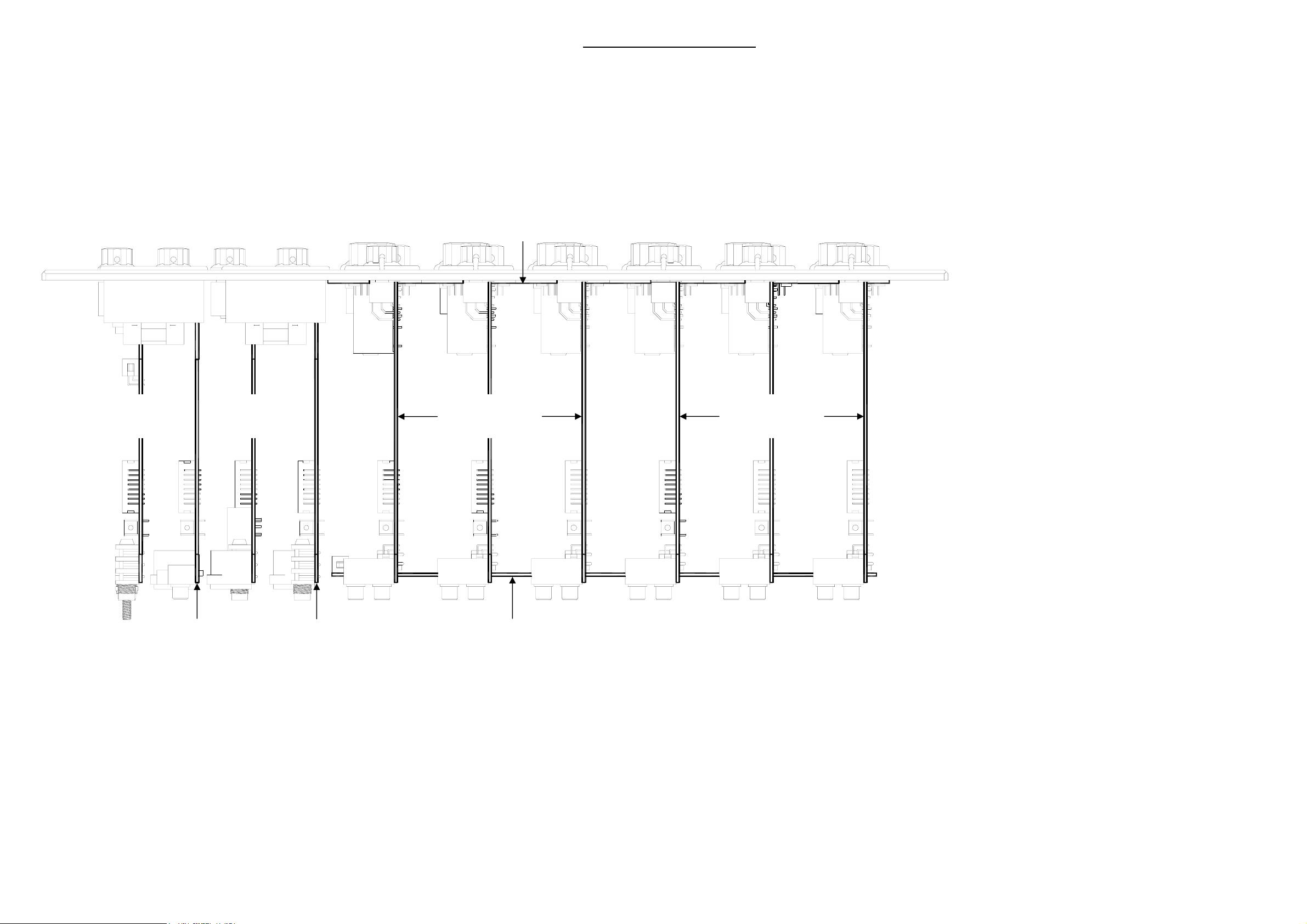
XONE:S6 Internal Layout
Product ...................................XONE:S6
Power Supply Versions .........MPS7-100
..............................................MPS7-120
XONE:S6 FRONT
PHONES PCB
003-054
MIC PCB
003-052
METER PCB
003-471
INPUT 4-6 PCBs
003-090
INPUT 1-3 PCBs
003-050
..............................................MPS7-220
..............................................MPS7-240
DC Cable Assembly ................. 002-583
Pack Assembly......................... 003-465
Main Assembly ......................... 003-466
Panel Assembly Front .............. 003-467
Chassis Assembly .................... 003-468
PSU Assembly ......................... 003-469
Cue Switch Cable Assembly .... 003-089
Fader Assembly ....................... 003-109
VU Meter Assembly.................. 003-110
Input 1-3 PCB........................... 003-050
BOOTH PCB
003-053
MASTER PCB
003-051
SLAVE PCB
003-472
Input 4-6 PCB........................... 003-090
Master PCB .............................. 003-051
Mic PCB ................................... 003-052
Booth PCB................................ 003-053
Phones PCB............................. 003-054
Meter PCB................................ 003-471
Slave PCB ................................ 003-472
Power PCB............................... 003-470
xones6_layout_1.doc Sheet 1 of 1
Page 7
R1
+30V
e
CN1B
B
d
LEFT_PRE_OUT
c
b
RIGHT_PRE_OUT
1R0
C47
47/63
1 2
1 2
L1
W
R
L4
JP7
1 2
1 2
JP8
JP1
JP2
100P/DISK
R62
100K 1%
R64
100K 1%
R82
2K7
R101
270K
C1
220P/DISK
C48
C51
100P/DISK
C2
220P/DISK
22N/MYL
22N/MYL
Q30
BC637
C34
VR2C
C35
VR2A
a
ALLEN&HEATH
Kernick Industrial Estate,
Penryn, Cornwall,
England. TR10 9LU
+44 (0)8707 556250
Tel:
+44 (0)8707 556251
Fax:
ABCDEFGH
+28VP
R85
82K
R40
10K 1%
79
C40
10/50
R86
82K
R41
10K 1%
13
C43
10/50
R4
47K 1%
R5
47K 1%
8
2
+28VP
R25
10K 1%
R24
10K 1%
Q1
NF
R8
22R
C29
470/35 LESR
R33
10K 1%
Q9
NF
R14
22R
R89
150K
C41
10/50
R90
150K
R91
150K
C44
10/50
R94
150K
ISSUE BY DATE
1 ARJ 27-08-02
1.1 ARJ 26-11-02
Q2
2SK170BLQ32SK170BLQ42SK170BL
R9
22R
R34
10K 1%
Q10
2SK170BL
R15
22R
Q21
2SC2240BL
C36
22N/MYL
R42
3K3 1%
11
Q22
2SC2240BL
C37
22N/MYL
R44
3K3 1%
5
R46
560R
Q17
2SC2240BL
R10
22R
R47
560R
Q19
2SC2240BL
Q11
2SK170BL
R16
22R
C38
22N/MYL
R43
1012
10K 1%
VR2D
C39
22N/MYL
R45
46
10K 1%
VR2B
1 2
2SC2240BL
Q6
2SK170BL
R13
22R
12
R69
2SC2240BL
Q20
2SK170BL
R19
22R
SW2A
3
1
SW2B
6
4
BRKT
7
SW2C
JP3
C15
47/25
CN1A
A
L
R
L
R
8
W
R
C9
100N 63V/PE
C14
47/25
JP4
CN6
SIL CABLE HEADER 3 M STRT
2
R106
68R
R107
68R
5
R49
3K3 1%
C7
220NC3680N
R56
470R
R11
22R
R51
3K3 1%
C8
220NC5680N
Q12
2SK170BL
R17
22R
R87
82K
R92
150K
R88
82K
R95
150K
FILE: AG4911_1.1 INPUT.Sch 15:45:06 23-Sep-2004
R93
150K
10/50
R96
150K
10/50
C42
C45
R57
470R
100K 1%
100K 1%
Q232SC2240BL
R54
3K3 1%
Q242SC2240BL
R55
3K3 1%
R26
10K 1%
C4
680N
R58
10K 1%
C6
680N
R60
+30VA
C12
100N 63V/PE
C18
100/25
-30VA
+30VC
C13
100N 63V/PE
C19
100/25
-30VC
BRKT
7
VR1C
POT9 10KA X2
SW APEM SPDT 5236WW X371 (AL4907)
R68
1K1 1%
R27
10K 1%
Q18
Q5
2SK170BL
R12
22R
1K1 1%
R36
R35
10K 1%
Q14
Q13
2SK170BL
R18
22R
R63
100K 1%
R65
100K 1%
BRKT
8
4
5
SW1B
SW APEM DPDT 5246W X371 (AL4906)
PRINTED:
C20
100N
C49
L2
100P/DISK
L3
C50
100P/DISK
1
2
3
CN2B
W
A
R
VALVE PCB FIXING
R104
100K 1%
METER +6.3V
METER_GND
C46
10/50
CN2A
W
B
R
CN7
1
2
3
4
R105
100K 1%
C21
100N
C23
C24
47/25
C22
100N
R100
100K 1%
C52
100P/DISK
L5
L6
C53
100P/DISK
47/25
8
7
R28
R29
100R
100R
RLY1B
R99
100K 1%
C25
47/25
C26
47/25
R102
R70
R103
47K 1%
47K 1%
R71
47K 1%
47K 1%
-30V
CUE_RD
10
L_MIX
CUE_L_MIX
BOOTH_L_MIX
MIX_CUE_L
+6.3V
-30V
R66
220K
R67
220K
RLY1A
5
6
5
7
9
11
13
15
EARTH SCREW TERMINAL
5
7
9
11
13
GND GND+30V
VR3A
POT P&G RF11 10KA X2_1
5 1
VR3B
POT P&G RF11 10KA X2_1
5 2
15
R108
22K 1%
3
R109
22K 1%
4
RLY2A
5
6
RLY SWBT53W/1
RLY2B
8
7
RLY SWBT53W/1
3
CN3
112
334
5
7
9
11
13
15
BOX 8X2 M 90 DEG
CN5
1
2
3
4
112
334
5
7
9
11
13
15
BOX 8X2 M 90 DEG
3
10
10
12
14
16
CN4
R97
39K
R98
39K
R6
47K 1%
6
8
10
12
14
16
6
8
R7
47K 1%
2
4
6
8
10
12
14
16
+30V
+6.3V
CUE_DC
2
4
6
8
10
12
14
16
R30
2
100R
VR1A
1 3
R37
5
100R
VR1B
4 6
R_MIX
CUE_R_MIX
BOOTH_R_MIX
MIX_CUE_R
+6.3V
L_MIX
R_MIX
CUE_L_MIX
CUE_R_MIX
R59
100K 1%
R31
10K 1%
Q15
R61
100K 1%
R38
10K 1%
+30V
-30V
+30V
-30V
AI1
HOLE-AI
Q7
R32
10K 1%
LD1
GRN
R39
10K 1%
LD2
GRN
HOLE-AI
2SK170BL
PR VA 500R
VR4
2
2SK170BL
PR VA 500R
VR5
2
R20
10R PF
R21
10R PF
R22
10R PF
R23
10R PF
AI2
+30VA
R80
120R
Q27
S
VP0610L
D
C27
R50
3K3 1%
-30VA
+30VC
R81
120R
Q28
S
VP0610L
D
C28
R53
3K3 1%
-30VC
R48
560R
CN8
2
1
SW APEM SPDT 5236WW X371 (AL4907)
R2
33R
SW1A
1
3
C16
100/25
C10
100N 63V/PE
C17
100/25
C11
100N 63V/PE
+6.3V
R3
33R
12
+
RLY2C
-
RLY SWBT53W/1
1
Q29
MPSA42
GND
R
12
2
L
Q25
MPSA42
R83
820R 1%
-30VA
Q26
MPSA42
R84
820R 1%
-30VC
TITLE:
Q8
2SK170BL
13
R72
22K 1%
JP5
Q16
2SK170BL
13
R75
22K 1%
JP9
C31
120/63 LESR
C30
120/63 LESR
C32
120/63 LESR
C33
120/63 LESR
R78
220R
G
R74
22K 1%
R73
22P/DISK
22K 1%
12
12
JP6
R79
220R
G
R77
22K 1%
R76
22P/DISK
22K 1%
12
12
JP10
+30VA
-30VA
+30VC
JST 2 M STRT
-30VC
+6.3V
XONE S6 INPUT PCB
PAGE:
DRG No: ISSUE: SHEET: OF
C 4911 1 1
1.1
RIGHT_PRE_OUT
CN9 JST 2 M STRT
2
D1
1
1N4148
R52
2K2 1%
RLY1C
+
RLY SWBT53W/1
LEFT_PRE_OUT
CUE_RD
GND
CUE_DC
1
-
GND
003-050_090 iss.1.1
Page 8

RIAA disable
CH1-3. For RIAA gain and
equalisation JP2, JP3, JP4 and JP8
are fitted. This is the factory default
setting. To disable RIAA and use
these inputs with line sources,
remove those jumpers and fit JP1
and JP7 instead.
Gain setting
CH1-6. The maximum preamp gain
available is set using these jumpers.
For +10dB gain all four jumpers
JP5, JP6, JP9 and JP10 are fitted.
This is the factory default setting.
To change this to +6dB gain fit JP5
and JP9 only. For 0dB gain remove
all four jumpers.
003-050_090 iss.1
Page 9

+30VA
R67
330R
Q9
2SC2240BL
R69
470R
D
Q13
2N3822
S
R12
330R
+30VB
R68
330R
Q10
2SC2240BL
R70
470R
D
Q17
2N3822
S
R14
330R
C26
47/63
R71
47K 1%
R74
47K 1%
C28
47/63
-30VA
-30VB
C33
100/25
100N
C34
100/25
100N
C6
C19
VR3A
1 2
2
1 3
POT18 10KA X2
VR3B
POT18 10KA X2
1 2
5
4 6
JP1
JUMP 2 STRT
R97
15K
JP2
JUMP 2 STRT
R98
15K
C7
100N
C35
10/50
C12
100N
C38
10/50
R64
100K
R75
33K
R65
100K
R76
33K
R4
10K 1%
C8
330N
Q14
2SK170BL
C9
330N
R5
10K 1%
R95
47K 1%
R7
10K 1%
C13
330N
Q18
2SK170BL
C20
330N
R10
10K 1%
R96
47K 1%
R77
3K3 1%
R18
R21
R78
3K3 1%
R81
3K3 1%
R23
R26
R84
3K3 1%
30K 2%
30K 2%
30K 2%
30K 2%
R19
30K 2%
C36
100/25
R20
30K 2%
Q15
2SK170BL
R87
1K2 1%
Q16
2SK170BL
R88
1K2 1%
R24
30K 2%
C39
100/25
R25
30K 2%
Q19
2SK170BL
R89
1K2 1%
Q20
2SK170BL
R90
1K2 1%
Q21
2SC2240
BC556B
R79
3K3 1%
Q22
2SC2240
BC556B
R85
3K3 1%
C37
100/25
Q11
2SC2240BL
R82
3K3 1%
C40
100/25
Q12
2SC2240BL
R86
3K3 1%
+30VA
R80
3K3 1%
Q23
-30VA
+30VA
120/63 LESR
-30VA
+30VB
R83
3K3 1%
Q24
-30VB
+30VB
120/63 LESR
-30VB
C10
100N
C42
120/63 LESR
120/63 LESR
C41
C11
100N
C43
C14
100N
C15
100N
C44
120/63 LESR
120/63 LESR
C48
C22
100N
C47
C21
100N
R32
100K 1%
R33
100K 1%
R42
100R
R34
100K 1%
R35
100K 1%
R37
100K 1%
R46
100R
R38
100K 1%
R40
100R
R41
100R
R43
100R
R47
100R
XLR NC3MBHR20
3
0
JACK SLIMJACK MET SW6
T
R44
100R
XLR NC3MBHR20
3
0
JACK SLIMJACK MET SW6
T
R48
100R
CN5
12
CN3
R
CN6
12
CN4
R
R72
47K 1%
R73
47K 1%
+30VB
+30VA
-30VA
-30VB
CN1
T
L_INS_S
CN2
T
R_INS_S
R
L_INS_R
R
R_INS_R
VR1A
POT18 20KB X2 CD
R49
5K6
C3
47N/MYL
R55
18K
POT18 20KB X2 CD
L_MIX
CUE_L_MIX
BOOTH_L_MIX
MIX_CUE_L
+6.3V
GND GND+30V
-30V
R52
5K6
R57
18K
5
7
9
11
13
15
EARTH SCREW TERMINAL
VR1B
POT18 20KB X2 CD
C16
47N/MYL
VR2B
POT18 20KB X2 CD
13
C23
2
2N7/MYL
R50
6K8
2
VR2A
BOX 8X2 M 90 DEG
5
R54
6K8
5
13
CN7
112
334
5
7
9
10
12
11
14
13
16
15
1
2
3
4
46
C24
2N7/MYL
46
C4
47N/MYL
6
8
CN8
C17
47N/MYL
R51
5K6
R56
18K
R53
5K6
R58
18K
2
4
6
8
10
12
14
16
-30VA
R59
620K 1%
C29
C5
1/63
R_MIX
CUE_R_MIX
BOOTH_R_MIX
MIX_CUE_R
+6.3V
-30VB
R60
620K 1%
C18
1/63
22P
C30
22P
R61
220K
C31
10/16
R62
220K
C32
10/16
G
R63
100K
MIX_CUE_L
MIX_CUE_R
G
R66
100K
+30VA
R2
10K 1%
R15
Q1A
VR4
2SK389
e
R1
10K 1%
PR VA 500R
2
LD1
GRN
Q3
MPSA42
R11
820R 1%
-30VA
13
L_MIX
Q1B
2SK389
220R
R3
10K 1%
G
R17
30K 2%
C1
22P/DISK
LD2
GRN
R27
120R
Q7
S
VP0610L
D
Q4
MPSA42
R28
120R
-30VA
R39
22R
R31
NF
BOOTH_L_MIX
BOOTH_R_MIX
d
+30VB
R6
10K 1%
R16
Q2A
VR5
2SK389
PR VA 500R
c
2
R8
10K 1%
LD3
GRN
+30V
b
-30V
R91
33R
R92
33R
R93
33R
R94
33R
Q5
MPSA42
R13
820R 1%
-30VB
C45
470/35 LESR
C49
470/35 LESR
Q2B
13
2SK389
R_MIX
220R
R9
10K 1%
G
R22
30K 2%
C2
22P/DISK
LD4
GRN
C46
470/35 LESR
C50
470/35 LESR
R29
120R
Q8
S
VP0610L
D
Q6
MPSA42
R30
120R
-30VB
R36
NF
R45
22R
a
ALLEN&HEATH
Kernick Industrial Estate,
Penryn, Cornwall,
England. TR10 9LU
+44 (0)8707 556250
Tel:
+44 (0)8707 556251
Fax:
ABCDEFGH
ISSUE BY DATE
1 ARJ 2-09-02
2 ARJ 31-10-02
AI1
HOLE-AI
FILE: AG4912 iss 2 Master.Sch 13:58:36 23-Sep-2004
AI2
HOLE-AI
PRINTED:
TITLE:
XONE S6 MASTER PCB
PAGE:
DRG No: ISSUE: SHEET: OF
C4912 1 1
2
003-052 iss.2
Page 10

Master output level
The output level with MASTER
control at maximum position and VU
meters reading '0' is +4dBu with JP1
and JP2 fitted. This is the default
factory setting. To change this to
0dBu remove JP1 and JP2. Access
these jumpers from below the
console.
003-052 iss.2
Page 11

JUMP 2 STRT
12
JP1
1 2
e
XLR NC3FBHR20 MET
d
c
R1
6K8 1%R26K8 1%
C1 10/50
3
CN1
C2
0
METER ILLUMINATION
JP2
1 2
JUMP 2 STRT
C3
C9
100N
330P
10/50
C4
100N
CN6
2
1
JST 2 M STRT
CN7
2
1
JST 2 M STRT
+30V
R11
R8
4K7 1%R94K7 1%
2K2 1%
GND
Q1
+6.3V
R3
6K8 1%R46K8 1%
R14
100R
2SB737
R12
3K3 2%
Q2
2SB737
R13
3K3 2%
L_MIX
CUE_L_MIX
BOOTH_L_MIX
MIX_CUE_L
+6.3V
GND GND+30V
-30V
P7
P3
P8
P4
P14
P10
+VA
POT18 20KB X2
5
VR3B
4 6
R10
3K3 1%
D1
1N4002D21N4002
-VA
CN2
112
334
5
5
7
9
11
13
15
1
2
3
4
CN4
P11
P12
6
8
10
12
14
16
CN5
4
7
9
11
13
15
BOX 8X2 M 90 DEG
EARTH SCREW TERMINAL
DC PWR SKT MALE 7 PIN CHASSIS
1
6 7
MALE
2
R_MIX
4
CUE_R_MIX
6
BOOTH_R_MIX
8
MIX_CUE_R
10
+6.3V
12
14
16
2
53
0
C10
220/10
P5
P6
P13
R15
2
3
R16
22K 1%
C11
22P/DISK
P1
P2
P9
C12
22K 1%
U1A
GND
22P/DISK
TL072
+30V
-30V
SW1C
BRKT
7
8
CN3
JACK SLIMJACK MET SW6
C5
100N
C15
1
47/25
R19
47R
R17
100K 1%
+30V
C20
100/25
C21
100/25
-30V
T
R6
6K8 1%
MPSA42
R26
20K 1%
R7
6K8 1%
R
Q4
Q3
MPSA92
C16
47/25
C6
100N
R18
100K 1%
5
6
R33
22R
R34
22R
U1B
2
1 3
VR1A
POT18 20KB X2 CD
7
TL072+
C22
100/25
C23
100/25
R20
4K7 1%
VR1B
POT18 20KB X2
47N/MYL
22N/MYL
8
U1C
V+
V-
TL072+
4
2
1 3
VR2A
POT18 20KB X2 CD
46
C19
5
10N/MYL
R21
6K8 1%
R5
6K8 1%
5
VR2B
C18
C24
6
5
R22
46
4K7 1%
POT18 20KB X2
C8
100N
U2B
C13
22P/DISK
TL072
8
U2C
V+
V-
4
7
TL072
VR3A
1 3
POT18 20KB X2
R23
4K7 1%
R24
2
10K 1%
+VA
-VA
SW1A
R35
100K 1%
C14
22P/DISK
R25
20K 1%
2
U2A
3
TL072
C7
100N
C17
1
47/25
L
3
1
R
SW1B
L
6
4
R
SW2A
1
3
SW2B
4
6
R27
47K 1%
R28
47K 1%
R29
30K 2%
R30
30K 2%
R31
47K 1%
R32
47K 1%
CUE_L_MIX
CUE_R_MIX
L_MIX
R_MIX
BOOTH_L_MIX
BOOTH_R_MIX
2
5
2
5
b
a
ALLEN&HEATH
Kernick Industrial Estate,
Penryn, Cornwall,
England. TR10 9LU
+44 (0)8707 556250
Tel:
+44 (0)8707 556251
Fax:
ABCDEFGH
AI1
HOLE-AI
AI2
HOLE-AI
ISSUE BY DATE
1 ARJ 20-09-02
1.1 ARJ 14-05-03
FILE: AG4913 ISS 1.1 Mic.Sch 13:44:03 23-Sep-2004
PRINTED:
TITLE:
XONE S6 MIC PCB
PAGE:
DRG No: ISSUE: SHEET: OF
C4913 1 1
1.1
003-052 iss.1.1
Page 12

j
Phantom power
30V phantom power is disabled
when JP1 is fitted. This is the
default factory setting. Plug the
umper on to JP2 instead if you wish
to turn phantom power on.
003-052 iss.1
Page 13

BOOTH_L_MIX
e
2
3
TL072
d
BOOTH_R_MIX
c
b
L_MIX
CUE_L_MIX
BOOTH_L_MIX
MIX_CUE_L
+6.3V
-30V
6
5
TL072
5
7
9
11
13
GND GND+30V
15
BOX 8X2 M 90 DEG
EARTH SCREW TERMINAL
a
ALLEN&HEATH
Kernick Industrial Estate,
Penryn, Cornwall,
England. TR10 9LU
+44 (0)8707 556250
Tel:
+44 (0)8707 556251
Fax:
ABCDEFGH
C1
R1
47K 1%
U1A
C4
R2
47K 1%
U1B
22P/DISK
22P/DISK
CN6
112
334
5
7
9
11
13
15
1
2
3
4
1
7
2
R_MIX
4
CUE_R_MIX
6
BOOTH_R_MIX
6
8
MIX_CUE_R
8
10
10
12
14
16
+6.3V
12
14
16
CN7
ISSUE BY DATE
R3
5K6
R9
18K
R6
5K6
R11
18K
ARJ1 30-08-02
POT18 20KB X2
C7
47N/MYL
POT18 20KB X2
POT18 20KB X2
C16
47N/MYL
POT18 20KB X2
VR1A
R5
13
5K6
C19
2
2N7/MYL
VR2A
VR1B
VR2B
2
C43
1/63
5
5
C44
1/63
R4
6K8
R8
6K8
C8
47N/MYL
R10
13
18K
R14
47K 1%
GND
R7
46
5K6
C20
2N7/MYL
C17
47N/MYL
R12
46
18K
R15
47K 1%
GND
FILE: AG4914 iss 1 Booth.Sch 14:00:03 23-Sep-2004
C2
22P/DISK
2
U2A
3
TL072
R13
100K 1%
D1
1N4148
2
U6A
3
TL072
C5
22P/DISK
6
U2B
5
TL072
R16
100K 1%
D3
1N4148
6
U6B
5
TL072
PRINTED:
1
1
7
7
AI1
HOLE-AI
C9
C21
100/25
D2
1N4148
C11
C24
100/25
D4
1N4148
100N
1 3
POT18 10KA X2
R51
1K0
100N
4 6
POT18 10KA X2
R52
1K0
AI2
HOLE-AI
VR3A
VR3B
2
R17
47K1%
R53
47K
GND GND
5
R18
47K1%
R54
47K
GND GND
AI3
HOLE-AI
3
U3A
2
R19
10K 1%
1 3
VR4
PR VA 10K
C45
10/16
5
U3B
6
R21
10K 1%
1 3
VR5
PR VA 10K
C46
10/16
TL072+
R20
10K 1%
C3
22P/DISK
2
TL072+
R22
10K 1%
C6
22P/DISK
2
1
JST 2 M STRT
7
CN4
CN5
1
2
1
2
R23
4K7 1%
R24
4K7 1%
R27
4K7 1%
R28
4K7 1%
JST 2 M STRT
+30V
C29
100/25
C30
100/25
-30V
2
3
R25
4K7 1%
R26
4K7 1%
6
5
2
3
R29
4K7 1%
R30
4K7 1%
6
5
U4A
R31
10K 1%
R32
10K 1%
U4B
U5A
R34
10K 1%
R37
10K 1%
U5B
R59
6K8 1%
MPSA42
R65
20K 1%
R60
6K8 1%
C35
22P/DISK
TL072
TL072
R35
10K 1%
C38
22P/DISK
TL072
TL072
R38
10K 1%
Q1
Q2
MPSA92
R33
10K 1%
1
C36
22P/DISK
C37
22P/DISK
7
C39
22P/DISK
R36
10K 1%
1
C40
22P/DISK
C41
22P/DISK
7
C42
22P/DISK
R39
47R
R40
R41
47R
R42
47R
47R
R61
10R PF
R62
10R PF
R63
10R PF
R64
10R PF
C10
100N
C22
100/25
R43
2K2 1%
R44
2K2 1%
C23
100/25
C12
100N
C13
100N
C25
100/25
R45
2K2 1%
R46
2K2 1%
C28
100/25
C18
100N
C31
100/25
C32
100/25
R47
100K 1%
R48
100K 1%
C14
100N
C26
100/25
C27
100/25
C15
100N
R49
100K 1%
R50
100K 1%
R55
820R 1%
R56
820R 1%
C33
100/25
C34
100/25
R57
820R 1%
R58
820R 1%
U1C
3
CN2
0
CN1
W
RCA PHONO H2H
R
3
CN3
0
8
V+
V-
TL072
4
XLR NC3MBHR20
12
XLR NC3MBHR20
12
+VA
U2C
TITLE:
8
4
U4C
8
V+
V-
4
TL072
V+
V-
TL072
U3C
8
4
-VA
V+
V-
TL072
XONE S6 BOOTH PCB
U5C
8
V+
V-
TL072
4
PAGE:
DRG No: ISSUE: SHEET: OF
C4914 1 1
1
U6C
+VB
8
V+
V-
4
TL072
-VB
003-053 iss.1
Page 14

003-053 iss.1
Page 15

CUE_L_MIX
e
d
CUE_R_MIX
c
b
MIX_CUE_L
C1
R1
100/25
100K 1%
C2
R3
100/25
100K 1%
MIX_CUE_R
C7
22P/DISK
R5
47K 1%
2
U1A
3
TL072
2
U2A
3
TL072
CN1
JACK SLIMJACK MET SW6
6
U2B
5
TL072
6
U1B
5
TL072
CN8
1
2
3
4
JACK SKT BRACKET
C8
22P/DISK
R7
39K
T
R
C10
22P/DISK
R8
39K
C11
22P/DISK
R6
47K 1%
1
1
7
7
R60
1R0
R61
1R0
330P/DISK
VDD
CUE_DC_5
CUE_DC_6
CUE_RD_1
CUE_RD_2
CUE_RD_3
VR2A
POT18 20KB X2
1 3
46
VR2B
POT18 20KB X2
C21
GND
2
5
R45
10K 1%
16
3
4
17
18
1
2
6
CUE_RD_1
CUE_RD_2
CUE_RD_3
CUE_RD_4
CUE_RD_5
CUE_RD_6
3
2
5
6
U6
OSC1/CLKIN
T0CKI
MCLR/VPP
RA0
RA1
RA2
RA3
RB0
U3A
TL072+
U3B
TL072+
14
OSC2/CLKOUT
VDD
VSS
PIC16C56RCE/P
5
GND
CN7
112
334
5
5
7
7
9
9
11
11
13
13
15
15
BOX 8X2 M STRT
1
7
VDD
C22
100N 100V/MLC
GND
RB1
RB2
RB3
RB4
RB5
RB6
RB7
VSS
6
8
10
12
14
16
2
CUE_DC_1
4
CUE_DC_2
6
CUE_DC_3
8
CUE_DC_4
10
CUE_DC_5
12
CUE_DC_6
14
16
C13
22N/MYL
C16
22N/MYL
15
7
8
9
10
11
12
13
R9
22K 1%
R15
3K3 1%
R10
22K 1%
R18
3K3 1%
CUE_RD_4
CUE_RD_5
CUE_RD_6
CUE_DC_1
CUE_DC_2
CUE_DC_3
CUE_DC_4
13
VR1A
POT18 20KB X2
2
6
5
46
VR1B
POT18 20KB X2
5
2
3
R46
10K 1%
CUE_RD_1
R16
3K3 1%
R11
22K 1%
U4B
TL072
R17
3K3 1%
R13
22K 1%
U4A
TL072
R47
10K 1%
CUE_RD_2
CN2
1
6
2
7
3
8
4
9
5
DB9FH(DMR)
C14
22N/MYL
7
C15
22N/MYL
1
R48
10K 1%
CUE_RD_3
R52
100R
R53
100R
R54
100R
R55
100R
R56
100R
R57
100R
VR3A
1 3
POT18 10KA X2
VR3B
4 6
POT18 10KA X2
R49
10K 1%
CUE_RD_4
CUE_DC_1
CUE_DC_6
CUE_DC_2
CUE_DC_3
CUE_DC_4
CUE_DC_5
2
47/25
5
47/25
CUE_RD_5
C17
C18
R50
10K 1%
R2
100K 1%
R4
100K 1%
R51
10K 1%
CUE_RD_6
3
2
R19
2K2 1%
5
6
R20
2K2 1%
100P/DISK
U5A
TL072+
R12
22K 1%
C9
22P/DISK
U5B
TL072+
R14
22K 1%
C12
22P/DISK
C25
1
C26
100P/DISK
7
R23
5K6
D1
1N4148
D2
1N4148
D5
1N4148
R24
5K6
R25
5K6
D3
1N4148
D4
1N4148
D6
1N4148
R26
5K6
AI1
HOLE-AI
C3
+30V
100/25
C4
100/25
-30V
R58
470R
TL431
GND
AI2
HOLE-AI
U7
Q1
TIP122
R33
4R7 1W
R34
4R7 1W
Q3
TIP127
+30VH
Q2
TIP122
R35
4R7 1W
R36
4R7 1W
Q4
TIP127
R27
6K8 1%
R59
20K 1%
R28
6K8 1%
C23
MPSA42
Q5
MPSA92
10/50
+30VH
-30VH
-30VH
Q11
R21
2K2 1%
R22
2K2 1%
R39
47R
R40
47R
Q8
BC637
R37
47R
R38
47R
100P/DISK
+6.3V
L1
L5
L2
L3
C28
R41
10R PF
R42
10R PF
VDD
C24
100/6.3
C29
100P/DISK
C30
100P/DISK
+VA
-VA
C27
100P/DISK
T
C32
100P
T
JACK SLIMJACK SW6
L6
R43
+30V
47R
R44
-30V
47R
U1C
C5
100/25
C6
100/25
TL072
R
C31
100P/DISK
R
GND
GND
8
V+
V-
4
L_MIX
CUE_L_MIX
BOOTH_L_MIX
MIX_CUE_L
+6.3V
GND GND+30V
-30V
EARTH SCREW TERMINAL
CN4
JACK H3 JALCO GOLD
L4
CN3
C19
120/63 LESR
C20
120/63 LESR
8
U2C
V+
V-
TL072
4
CN5
112
334
5
5
+30VH
-30VH
U3C
TL072
6
7
8
9
10
12
11
14
13
16
15
1
2
3
4
8
V+
V-
4
7
9
11
13
15
BOX 8X2 M 90 DEG
GND
CN6
2
R_MIX
4
CUE_R_MIX
6
BOOTH_R_MIX
8
MIX_CUE_R
10
+6.3V
12
14
16
8
U4C
V+
V-
TL072
4
U5C
TL072
8
V+
V-
4
a
ALLEN&HEATH
Kernick Industrial Estate,
Penryn, Cornwall,
England. TR10 9LU
+44 (0)8707 556250
Tel:
+44 (0)8707 556251
Fax:
ABCDEFGH
ISSUE BY DATE
1 ARJ 02-09-02
FILE: AG4915 ISS 1 Phones.Sch 14:05:28 23-Sep-2004
PRINTED:
TITLE:
XONE S6 PHONES PCB
PAGE:
DRG No: ISSUE: SHEET: OF
C4915 1 1
1
003-054 iss.1
Page 16

003-054 iss.1
Page 17

CN1
L
FILTERED IEC
E
N
IEC FILTERED MAINS INLET
MAINS
INLET
e
d
+V_UNREG
c
100K 1%
D14
BZV85C20V
b
R16
3K3 1%
1
2
U4
COLL
AN
EMIT
K
NC3NC
4N35
-V_UNREG
a
ALLEN&HEATH
Kernick Industrial Estate,
Penryn, Cornwall,
England. TR10 9LU
+44 (0)8707 556250
Tel:
+44 (0)8707 556251
Fax:
ABCDEFGH
R6
MPSA42
R35
120R
5
4
6
L
E
N
R37
R40
15K
120K
LD1
D15
BZV85C20V
LED T1 3MM RED
Q5
BC549
D24
R41
68K
1N5819
ISSUE BY DATE
1 ARJ 27-05-05
+V_UNREG
2200/16
+V_UNREG
R51
1K5
8
V+
V-
NE5532
4
R52
1K5
-V_UNREG
0
AGRND
P16
PIN
C6
6800/80
C7
6800/80
C17
2200/16
1
67
VU_ILLUM
R53
120R
R54
470R
P1
P8
PIN
PIN
P2
P33
PIN
PIN
-V_UNREG
C29
D16
BZX79C12V
D17
BZX79C12V
P13
+6.3V
P14
AGRND
F2
1 2
TE5 T1A
D20
1N4002
LED T1 3MM GREEN
+V_PRE_REG
P3
PIN
P15
P6
+6.3V
PIN
LD4
R50
3K3
NTC1
1
3
2
P7
PIN
1M2 1/2W
R62
CN2 CN4
CN3 CN5
F1
1 2
FUSE HOLDER 20MM
110/120
P19P18
BWN
P1
RED
BLK
P2
WHI
C30
4N7/MYL
T2
CN10
BLK
S1
ORA
0V
S2
YEL
BLU
S3
WHI
R48
9K1 2%
R49
820R 1%
R29
10K 1%
R30
10K 1%
CHOKE 10UH (AM3903)
CN11
CN12
CN13
CN14
L2
(AM3903)
470/35 LESR
LED T1 3MM GREEN
470/35 LESR
L3
D18
1N4002
C21
BZX79C12V
C22
CN9
CN6
CN7
CN8
R22
0R22 2.5W
D8
1N4148
D9
1N4148
R42
22K 1%
R28
10K 1%
C18
33/16
C31
U5
10/50
TL431
R20
4K7 1%
R43
22K 1%
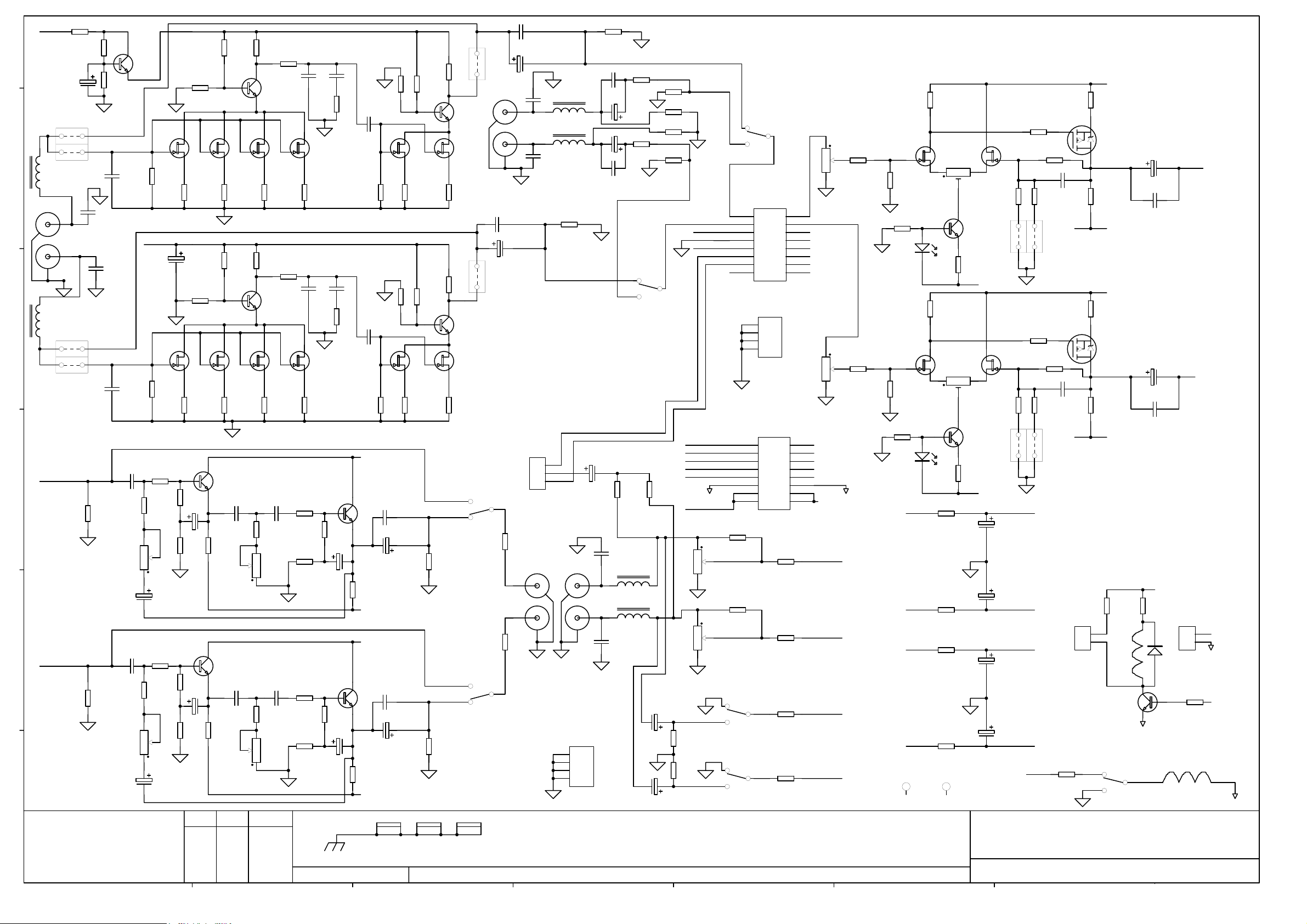
FILE: AG4918 EDIT ISS 1 Power supply.Sch 10:18:10 14-Jun-2005
Q2
C20
2
U2A
3
C19
6
U2B
5
NE5532
D12
1N4148
D13
1N4148
R23
0R22 2.5W
FH1
FH4 FH7
FH2
FH5
FH3 FH6
C26
10/16
NE5532
10/16
C27
FH8
FH9
R44
47R
Q7
MPSA92
2N7/MYL
1
7
2N7/MYL
Q6
MPSA42
R45
47R
FH10
R46
3K3 1%
R57
1K5
R59
3K3 1%
R14
47K 1%
R33
150R
1N4148
D10
R34
R15
47K 1%
TO IMPROVE HOT START WITH ALL OPTIONS CHANGE
R44/R45 FROM 47R TO 33R
R46/R47 FROM 3K3 TO 4K7
1N4148
150R
R36
3K3 1%
R58
1K5
R47
3K3 1%
NOTE
TO CN16
P20
P17
PKGN BL RD
Q12
MPSA42
D25
Q9
D11
GN PK BL RD
1N4148
MPSA42
Q8
MPSA92
P25 P26
T0 CN18
D26
1N4148
Q13
MPSA92
P27 P28
INRUSH SUPP NTC20R
+30V
P4
R38
PIN
15K
LD2
Q11
S
D23
G
R61
330R
CN18
4
SIL 4 M STRT LCK
LD3
LED T1 3MM GREEN
R39
15K
P5
-30V
PIN
D21
1N4002
D
IRF540N
BZX79C12V
123
PRINTED:
Q10
S
D22
R60
330R
CN16
SIL 4 M STRT LCK
3
Vin
CN19
4
SIL 4 M STRT LCK
CN9
CN6
CN7
CN8
G
IRF9540N
4
U7
ADJ
1
220/240
BWN
P1
RED
BLK
P2
WHI
D
123
Vout
LM317T
C25
100N MLC
123
T2
CN10
BLK
S1
CN11
ORA
0V
S2
CN12
YEL
BLU
CN13
S3
CN14
WHI
BR RECTIFIER (AE3477)
U6
3
Vin
CN17
SIL 4 M STRT LCK
2
TITLE:
Vout
ADJ
LM317T
1
C28
100N MLC
123
4
+V_PRE_REG
R55
RD PK GN BL
22R 2.5W
RD PK GN BL
R56
22R 2.5W
XONE S6 POWER SUPPLY
PAGE:
DRG No: ISSUE: SHEET: OF
C4918 1 1
DGRND
P21
P29
2
+30V
-30V
23
23
BR2
P9
P10
P11
D19
1N4002
P30
BR3
14
BR KBU6J
14
C16
2200/16
C23
100/25
U2C
C24
100/25
DC PWR SKT FEMALE 7 PIN CHASSIS
2
5 3
CN15
FEMALE
P23P22 P24
P31
P32
4
P12
1
003-470 iss.1
Page 18

003-470 iss.1
Page 19

C3
4.7/20T_S
GND_1
R6
22K
C2
4.7
R2
R3
10K
R5
470K
R7
82K
GND_1
CN1
e
1
2
3
GND_1
R1
47K 0805
10K
R4
470K
C1
1/50_S
GND_1
1
16
5
4
3
2
6
U1
VCC
VREF2
OUT
VINVIN+
VREF1
GND
LB1409 SMD
D1
D2
D3
D4
D5
D6
D7
D8
D9
LD1
LD2
7
LD3
8
9
10
11
12
13
14
15
LD4
LD5
LD8
GREEN
GREEN
GREEN
LD6
GREEN
LD7
GREEN
RED
RED
R15
RED
R8
R9
R10
R11
R12
R13
R14
470R
470R
470R
470R
470R
330R
330R
330R
CN1_1
1
2
3
GND_2
R1_1
47K 0805
10K
470K
C1_1
C2_1
R2_1
R4_1
GND_2
R6_1
22K
1/50_S
4.7
R3_1
10K
R5_1
470K
R7_1
82K
GND_2
1
16
5
4
3
2
6
C3_1
4.7/20T_S
GND_2
U1_1
VCC
VREF2
OUT
VINVIN+
VREF1
GND
LB1409 SMD
C3_2
GREEN
GREEN
GREEN
LD6_1
GREEN
LD7_1
GREEN
RED
RED
R15_1
RED
R8_1
470R
R9_1
470R
R10_1
470R
R11_1
470R
R12_1
470R
R13_1
330R
R14_1
330R
330R
CN1_2
1
2
3
GND_3
R1_2
47K 0805
10K
470K
C1_2
C2_2
R2_2
R4_2
GND_3
R6_2
22K
1/50_S
4.7
R3_2
10K
R5_2
470K
R7_2
82K
GND_3
16
LD1_1
LD2_1
7
D1
D2
D3
D4
D5
D6
D7
D8
D9
LD3_1
8
9
10
11
12
13
14
15
LD4_1
LD5_1
LD8_1
GND_3
U1_2
1
5
4
3
2
6
LB1409 SMD
4.7/20T_S
VCC
VREF2
OUT
VINVIN+
VREF1
GND
GREEN
GREEN
GREEN
LD6_2
GREEN
LD7_2
GREEN
RED
RED
R15_2
RED
R8_2
470R
R9_2
470R
R10_2
470R
R11_2
470R
R12_2
470R
R13_2
330R
R14_2
330R
330R
LD1_2
LD2_2
7
D1
D2
D3
D4
D5
D6
D7
D8
D9
LD3_2
8
9
10
11
12
13
14
15
LD4_2
LD5_2
LD8_2
d
C3_3
4.7/20T_S
GND_4
R6_3
10K
470K
C1_3
C2_3
R2_3
R4_3
GND_4
22K
1/50_S
4.7
R3_3
10K
R5_3
470K
R7_3
82K
GND_4
c
CN1_3
1
2
3
GND_4
R1_3
47K 0805
1
16
5
4
3
2
6
U1_3
VCC
VREF2
OUT
VINVIN+
VREF1
GND
LB1409 SMD
D1
D2
D3
D4
D5
D6
D7
D8
D9
LD1_3
LD2_3
7
LD3_3
8
9
10
11
12
13
14
15
LD4_3
LD5_3
LD8_3
b
FID1
FIDUCIAL
FID2
FIDUCIAL
GREEN
GREEN
GREEN
LD6_3
GREEN
LD7_3
GREEN
RED
RED
R15_3
RED
R8_3
470R
R9_3
470R
R10_3
470R
R11_3
470R
R12_3
470R
R13_3
330R
R14_3
330R
330R
CN1_4
1
2
3
GND_5
R1_4
47K 0805
FID P1
FIDUCIAL
R6_4
22K
C2_4
4.7
R2_4
R3_4
10K
470K
C1_4
R4_4
GND_5
10K
R5_4
470K
1/50_S
PANEL COMPS
FID P2
FIDUCIAL
16
R7_4
82K
GND_5
FID P3
FIDUCIAL
1
5
4
3
2
6
C3_4
4.7/20T_S
GND_5
U1_4
VCC
VREF2
OUT
VINVIN+
VREF1
GND
LB1409 SMD
C3_5
GREEN
GREEN
GREEN
LD6_4
GREEN
LD7_4
GREEN
RED
RED
R15_4
RED
R8_4
470R
R9_4
470R
R10_4
470R
R11_4
470R
R12_4
470R
R13_4
330R
R14_4
330R
330R
CN1_5
1
2
3
GND_6
R1_5
47K 0805
10K
470K
C1_5
C2_5
R2_5
R4_5
GND_6
R6_5
22K
1/50_S
4.7
R3_5
10K
R5_5
470K
R7_5
82K
GND_6
16
LD1_4
LD2_4
7
D1
D2
D3
D4
D5
D6
D7
D8
D9
LD3_4
8
9
10
11
12
13
14
15
LD4_4
LD5_4
LD8_4
GND_6
U1_5
1
5
4
3
2
6
LB1409 SMD
4.7/20T_S
VCC
VREF2
OUT
VINVIN+
VREF1
GND
GREEN
GREEN
GREEN
LD6_5
GREEN
LD7_5
GREEN
RED
RED
R15_5
RED
R8_5
470R
R9_5
470R
R10_5
470R
R11_5
470R
R12_5
470R
R13_5
330R
R14_5
330R
330R
LD1_5
LD2_5
7
D1
D2
D3
D4
D5
D6
D7
D8
D9
LD3_5
8
9
10
11
12
13
14
15
LD4_5
LD5_5
LD8_5
FH1 FH3 FH5 FH7 FH9 FH11FH13FH15FH17FH19FH21FH23
FH2 FH4 FH6 FH8 FH10FH12FH14FH16FH18FH20FH22FH24
a
ALLEN&HEATH
Kernick Industrial Estate,
Penryn, Cornwall,
England. TR10 9LU
+44 (0)8707 556250
Tel:
+44 (0)8707 556251
Fax:
ABCDEFGH
ISSUE BY DATE
1 ARJ 27-05-05
AI P1
HOLE-AI
CHK
BY
FILE: C4916_2 S6 LED METER.Sch 09:55:53 14-Jun-2005
AI P2
HOLE-AI
AI P3
HOLE-AI
AI P4
HOLE-AI
PRINTED:
TITLE:
XONE S6 LED METERS PCB
PAGE:
DRG No: ISSUE: SHEET: OF
C4916 1 1
1
003-471 iss.1
Page 20

003-471 iss.1
Page 21

IN_1_L
IN_1_R OUT_1_R
-30V1
CUE_RD_1
+6.3V1
GND 1 GND 2 GND 3 GND 4 GND 5 GND 6
e
CN1
112
334
5
5
7
7
9
9
11
11
13
13
15
15
IDC 8X2 F STRT
IN_1_L OUT_1_L
IN_1_R OUT_1_R
JP1
LINK OPT
JP2
LINK OPT
2
OUT_1_L
4
6
+30V1
6
8
+6.3V1
8
10
10
12
14
16
CUE_DC_1
12
14
16
IN_2_L
IN_2_R OUT_2_R
-30V2
CUE_RD_2
+6.3V2
CN2
112
334
5
5
7
7
9
9
11
11
13
13
15
15
IDC 8X2 F STRT
IN_2_L OUT_2_L
IN_2_R OUT_2_R
JP3
LINK OPT
JP4
LINK OPT
2
OUT_2_L
4
+30V2
6
6
8
+6.3V2
8
10
10
12
14
16
CUE_DC_2
12
14
16
IN_3_L
IN_3_R OUT_3_R
-30V3
CUE_RD_3
+6.3V3 +6.3V4 +6.3V5 +6.3V6
CN3
112
334
5
5
7
7
9
9
11
11
13
13
15
15
IDC 8X2 F STRT
IN_3_L OUT_3_L
IN_3_R OUT_3_R
JP5
LINK OPT
JP6
LINK OPT
2
OUT_3_L
4
+30V 3
6
6
8
+6.3V3
8
10
10
12
14
16
CUE_DC_3
12
14
16
IN_4_L
IN_4_R OUT_4_R
-30V4
CUE_RD_4
CN4
112
334
5
5
7
7
9
9
11
11
13
13
15
15
IDC 8X2 F STRT
IN_4_L OUT_4_L
IN_4_R OUT_4_R
JP7
LINK OPT
JP8
LINK OPT
2
OUT_4_L
4
+30V4
6
6
8
+6.3V4
8
10
10
12
14
16
CUE_DC_4
12
14
16
IN_5_L
IN_5_R OUT_5_R
-30V5
CUE_RD_5
CN5
112
334
5
5
7
7
9
9
11
11
13
13
15
15
IDC 8X2 F STRT
IN_5_L OUT_5_L
IN_5_R OUT_5_R
JP9
LINK OPT
JP10
LINK OPT
2
OUT_5_L
4
+30V5
6
6
8
+6.3V5
8
10
10
12
14
16
CUE_DC_5
12
14
16
IN_6_L
IN_6_R OUT_6_R
-30V6
CUE_RD_6
CN6
112
334
5
5
7
7
9
9
11
11
13
13
15
15
IDC 8X2 F STRT
IN_6_L OUT_6_L
IN_6_R OUT_6_R
JP11
LINK OPT
JP12
LINK OPT
2
OUT_6_L
4
+30V6
6
6
8
+6.3V6
8
10
10
12
14
16
CUE_DC_6
12
14
16
d
CUE_RD_1
CUE_RD_2
CUE_RD_3
CUE_RD_4
CUE_RD_5
CUE_RD_6
CN7
112
334
5
5
7
7
9
9
11
11
13
13
15
15
BOX 8X2 M STRT
2
CUE_DC_1
4
CUE_DC_2
6
CUE_DC_3
6
8
CUE_DC_4
8
10
10
12
14
16
CUE_DC_5
12
CUE_DC_6
14
16
c
b
FH1 FH2 FH3 FH4 FH5 FH6
a
ALLEN&HEATH
Kernick Industrial Estate,
Penryn, Cornwall,
England. TR10 9LU
+44 (0)8707 556250
Tel:
+44 (0)8707 556251
Fax:
ABCDEFGH
AI1
HOLE-AI
ISSUE BY DATE
1 ARJ 27-05-05
AI2
HOLE-AI
Value changes
FILE: AG4917 ISS 1 EDIT S6 SALVE CARD.Sch 09:32:45 14-Jun-2005
PRINTED:
TITLE:
XONE S6 SLAVE PCB
PAGE:
DRG No: ISSUE: SHEET: OF
C4917 1 1
1
003-472 iss.1
Page 22

003-472 iss.1
 Loading...