

Page 1
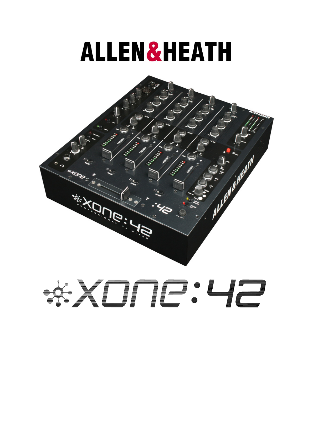
USER GUIDE
Publication AP6857
Allen & Heath 1 XONE:42 User Guide
Page 2

Limited One Year Warranty
This product is warranted to be free from defects in materials or
workmanship for period of one year from the date of purchase by the
original owner.
To ensure a high level of performance and reliability for which this
equipment has been designed and manufactured, read this User Guide
before operating. In the event of a failure, notify and return the
defective unit to ALLEN & HEATH Limited or its authorised agent as
soon as possible for repair under warranty subject to the following
conditions
Conditions Of Warranty
The equipment has been installed and operated in accordance with the
instructions in this User Guide.
The equipment has not been subject to misuse either intended or
accidental, neglect, or alteration other than as described in the User
Guide or Service Manual, or approved by ALLEN & HEATH.
Any necessary adjustment, alteration or repair has been carried out by
ALLEN & HEATH or its authorised agent.
This warranty does not cover fader wear and tear.
The defective unit is to be returned carriage prepaid to ALLEN &
HEATH or its authorised agent with proof of purchase.
Units returned should be packed to avoid transit damage.
In certain territories the terms may vary. Check with your ALLEN &
HEATH agent for any additional warranty which may apply.
This product complies with the European Electro magnetic Compatibility
directives 89/336/EEC & 92/31/EEC and the European Low Voltage
Directives 73/23/EEC & 93/68/EEC.
This product has been tested to EN55103 Parts 1 & 2 1996 for use in
Environments E1, E2, E3, and E4 to demonstrate compliance with the
protection requirements in the European EMC directive 89/336/EEC.
During some tests the specified performance figures of the product were
affected. This is considered permissible and the product has been passed as
acceptable for its intended use. Allen & Heath has a strict policy of
ensuring all products are tested to the latest safety and EMC standards.
Customers requiring more information about EMC and safety issues can
contact Allen & Heath.
XONE:42 User Guide AP6857 Issue 4
Copyright © 2007 Allen & Heath Limited. All rights reserved
Allen & Heath Limited
Kernick Industrial Estate, Penryn, Cornwall, TR10 9LU, UK
http://www.allen-heath.com http://www.xone.co.uk
Allen & Heath 2 XONE:42 User Guide
Page 3
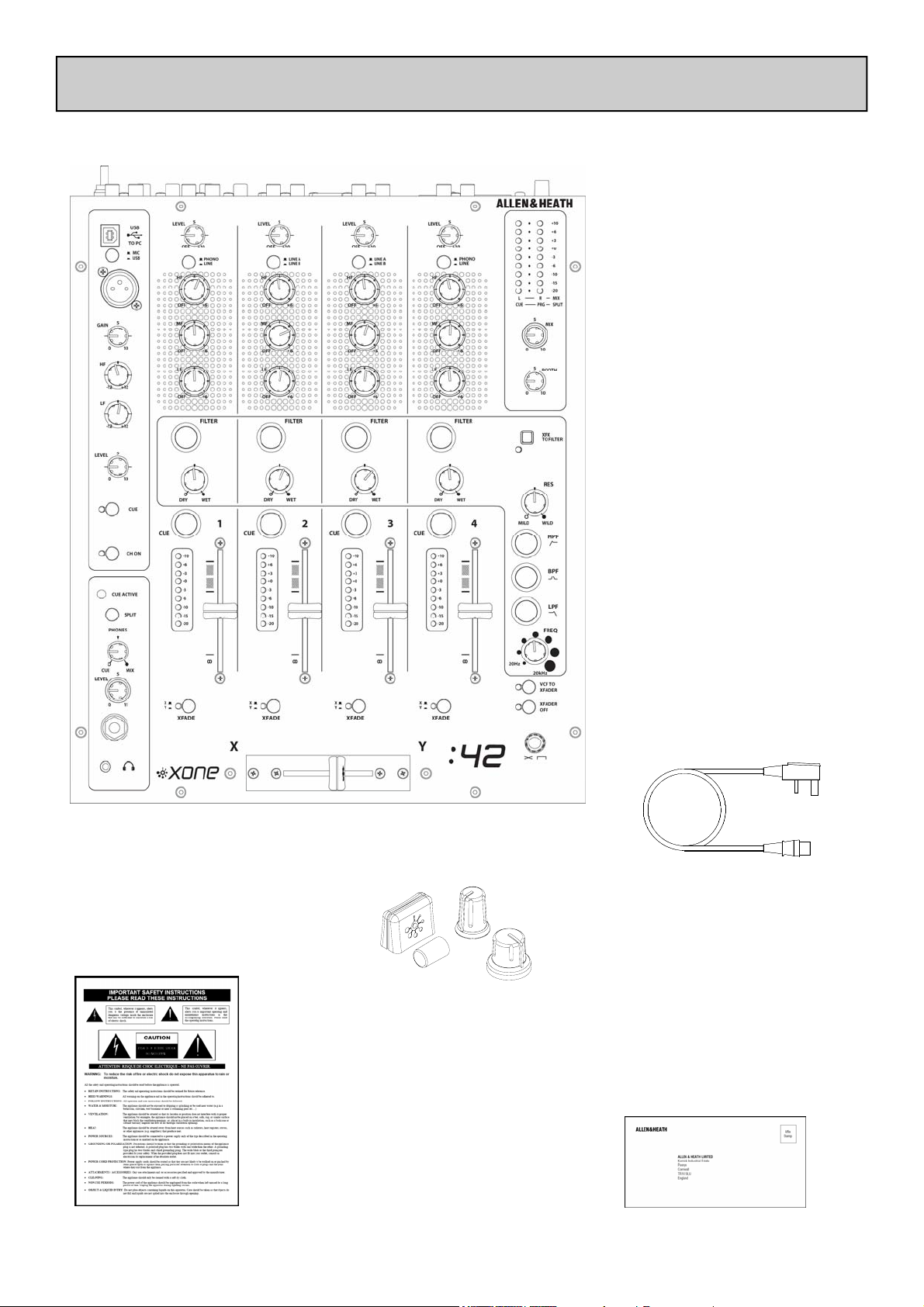
PACKED ITEMS
Check that you have received the following:
Xone:42 mixer
Mains Lead
Check that the correct
mains plug is fitted.
Spare knobs
and buttons
Safety Sheet
Important ! Read this sheet
before starting.
Retain for future reference.
Allen & Heath 3 XONE:42 User Guide
Registration Card
Complete and return
to Allen & Heath to
register your product.
Page 4

CONTENTS
Congratulations on purchasing the Allen & Heath Xone:42 performance DJ
mixer. To ensure that you get the maximum benefit from the unit please
spare a few minutes familiarizing yourself with the controls and setup
procedures outlined in this user guide. For further information please
refer to the additional information available on our web site, or contact
our technical support team.
http://www.xone.co.uk
http://www.allen-heath.com
Warranty......................................................... 2
Packed Items.................................................. 3
Contents ......................................................... 4
Panel Drawings.............................................. 5
Introduction ................................................... 6
Specifications.................................................. 7
Block Diagram ............................................... 8
Mic / USB Channel Input............................. 9
Phono / Line Input Channels 1 and 4....... 11
Line / Line Input Channels 2 and 3 ........... 13
Filters Section ................................................ 14
Headphone Section ...................................... 16
Master Section............................................... 17
Crossfader...................................................... 18
Rear Connectors .......................................... 19
USB Connection ........................................... 22
Filter Reference............................................. 23
Operating Levels........................................... 24
Earthing ........................................................... 25
Replacing the Crossfader / Face Plate...... 26
User-Replaceable Parts................................ 27
“You’ve tried it your way, now try it ours …”
Allen & Heath 4 XONE:42 User Guide
Page 5
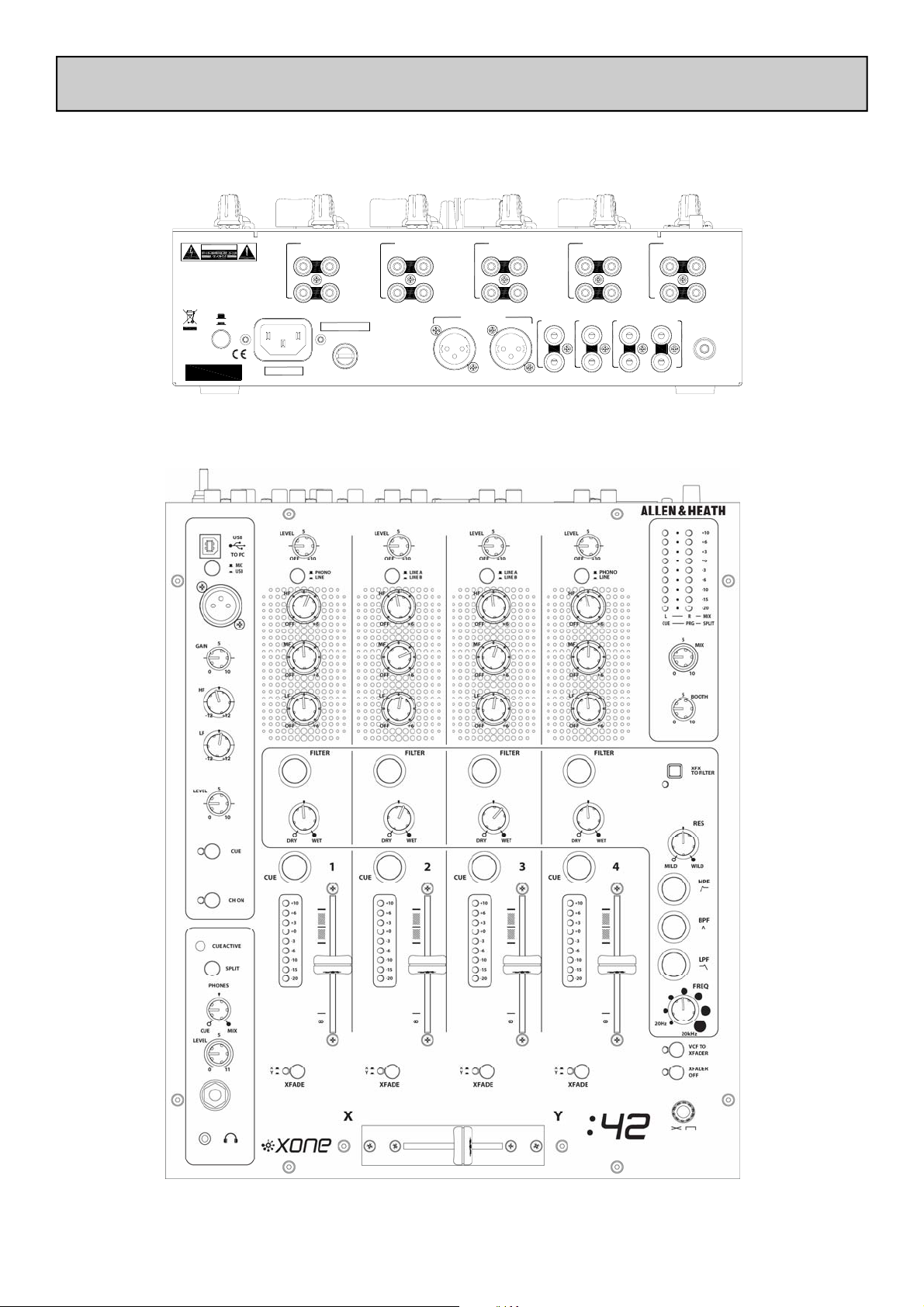
Rear Panel
PANEL DRAWINGS
WARNING:
FOR CONTINUED PROTECTION AGAINST RISK OF FIRE
REPLACE FUSE WITH SAME TYPE AND RATING.
ATTENTION: REMPLACER PAR UN FUSIBLE
STRICTEMENT IDENTIQUE EN VALEURS.
WARNING: THIS APPARATUS MUST BE EARTHE D.
TO REDUCE THE RISK OF FIRE OR ELECTRIC SHOCK
DO NOT EXPOSE APPAR ATUS TO RAIN OR MOISTURE.
SERIAL No:
Front Panel
CAUTION
0
I
X:FX SND
L
R
LINE
L
R
INPUT 1
LRPHONO
LR
X:FX RTN
USB AUDIO
LROUT
IN
LR
RECORD
BOOTH
L
L
R
R
INPUT 4
LR
LINE
LR
AC MAINS IN ~
OFF
ON
100 - 240V~
47-63Hz ~ 30W MAX
T500mAL 250V 20mm
FUSE
MADE IN THE UK BY ALLEN & HEATH LIMITED
A
LINE
B
INPUT 3
LR
LR
INPUT 2
LRPHONO
LINELINE
A
LINE
LR
B
MIX OUT
LEFT RIGHT
Allen & Heath 5 XONE:42 User Guide
Page 6

INTRODUCTION TO THE XONE:42
The Xone:42 is a high performance 12” analogue DJ mixer featuring four stereo dual input channels, a
Mic/USB channel, 60mm linear VCA channel faders, an analogue VCF filter, and the new X:FX external
effects loop with wet/dry control.
This mixer is designed to seamlessly interface with current leading-edge DJ technology, and may be used
by the widest range of DJs - from those who keep it in the bedroom, to regular performers and professionals. The same rugged build quality of vertical circuit board construction that is used throughout the
Xone range ensures that the Xone:42 can deal with any environment expected of it, and its ergonomic,
intuitive layout and stylish graphics make the Xone:42 one of the most easy-to-use hi-tech mix tools
around.
Each of the four main stereo channels is equipped with a powerful three band equalizer providing a safe
+6dB of boost and total kill for complete frequency isolation. Nine point metering on each channel allows for precise matching of signal levels, and smooth VCA faders help to ensure a perfect mix. Individual
channels can be routed to either side of the 45mm VCA crossfader, which has an adjustable curve control
for smooth mixes or virtually instant attack suitable for scratching.
The Xone:42 incorporates the X:FX system that enables an external effects processor to be easily interfaced, with a single knob controlling the proportion of the channel signal sent to the effects unit, from 0%
(dry) to 100% (wet).
The Xone:42 is also equipped with the legendary Xone VCF filter system. Each of the four main channels
can be individually routed to the filter, and the X:FX Return to Filter function allows channel signals that
have been through an external effects unit to be subsequently routed through the filter. Three basic filter
types can be selected: hi-pass, band-pass and low-pass. These filter types can be added together to create
other filter types; for example, hi-pass and low-pass together create a notch filter. Each filter type can be
swept from 20Hz to 20 kHz by the rotary frequency control, whilst resonance can be set from “mild” to
“wild”. A filter reference is included towards the end of this User Guide.
The mixer incorporates a USB audio interface for easy connection to a computer and integration of digital media. It can be used to play back music files from a laptop and to record mixes from the Xone:42, or
when used with appropriate software, as a digital DJ effects unit that can be patched into the X:FX. The
USB input combines with an XLR microphone input to provide an additional channel with two band +/12dB EQ and rotary level control.
A powerful headphone amp ensures more than adequate monitor level, while two separate headphone
sockets are provided on 3.5mm and ¼” Jack. A split cue feature allows the cue signal to be monitored in
the left headphone and the main mix in the right.
The master section has individual controls for the main mix and booth. Stereo nine point output meters
display the post master level output, or the pre-fade source level when a cue is selected. In split cue
mode the left meter displays the cue level and the right meter the master output.
A dedicated booth output, record out at -8dBu, and balanced main mix outputs on XLR round off the
Xone:42’s impressive list of features.
Allen & Heath 6 XONE:42 User Guide
Page 7

SPECIFICATIONS
Nom / max output levels Main Mix +4dBu +27dBu
Booth 0dBu +22dBu
X:FX Send 0dBu +20dBu
Record Out -10dBV +10dBV
Internal headroom Channels +22dB
Frequency response +/-0.5dB 10Hz - 20kHz
Distortion < 0.03% THD+noise @1kHz
Crosstalk < -90dB inter-channel
Mic EIN 22Hz-22kHz -126dB 150 ohm source
Residual noise Mix 1 -94dBu
Booth -101dBu
X:FX -92dBu
Rec -95dBu
Mix noise Mix 1 -80dBu (-84dB S/N)
Booth -84dBu (-82dB S/N)
X:FX -88dBu (-84dB S/N)
Rec -90dBu
Channel meters Peak reading 9 LED -20dB to +10dB
Main meters Peak reading 9 LED -20dB to +10dB
Mic EQ 2-Band +/-12dB
Channel EQ 3-Band +6dB / total kill
Channel fader 60mm stereo VCA, < -90dB shutoff
Crossfader 45mm stereo VCA - replaceable
Filters Stereo VCF, analogue
Consumption 30W max
Dimensions and Weights
The console is fitted with rubber feet for desktop operation.
Width Height Depth Weight
Mixer 305 mm (12“) 84 mm (3.3“) 358 mm (14”) 5 kg (11 lbs)
Packed 490 mm (19.5”) 205 mm (8.1”) 450 mm (17.7”) 7 kg (15.4 lbs)
Allen & Heath 7 XONE:42 User Guide
Page 8
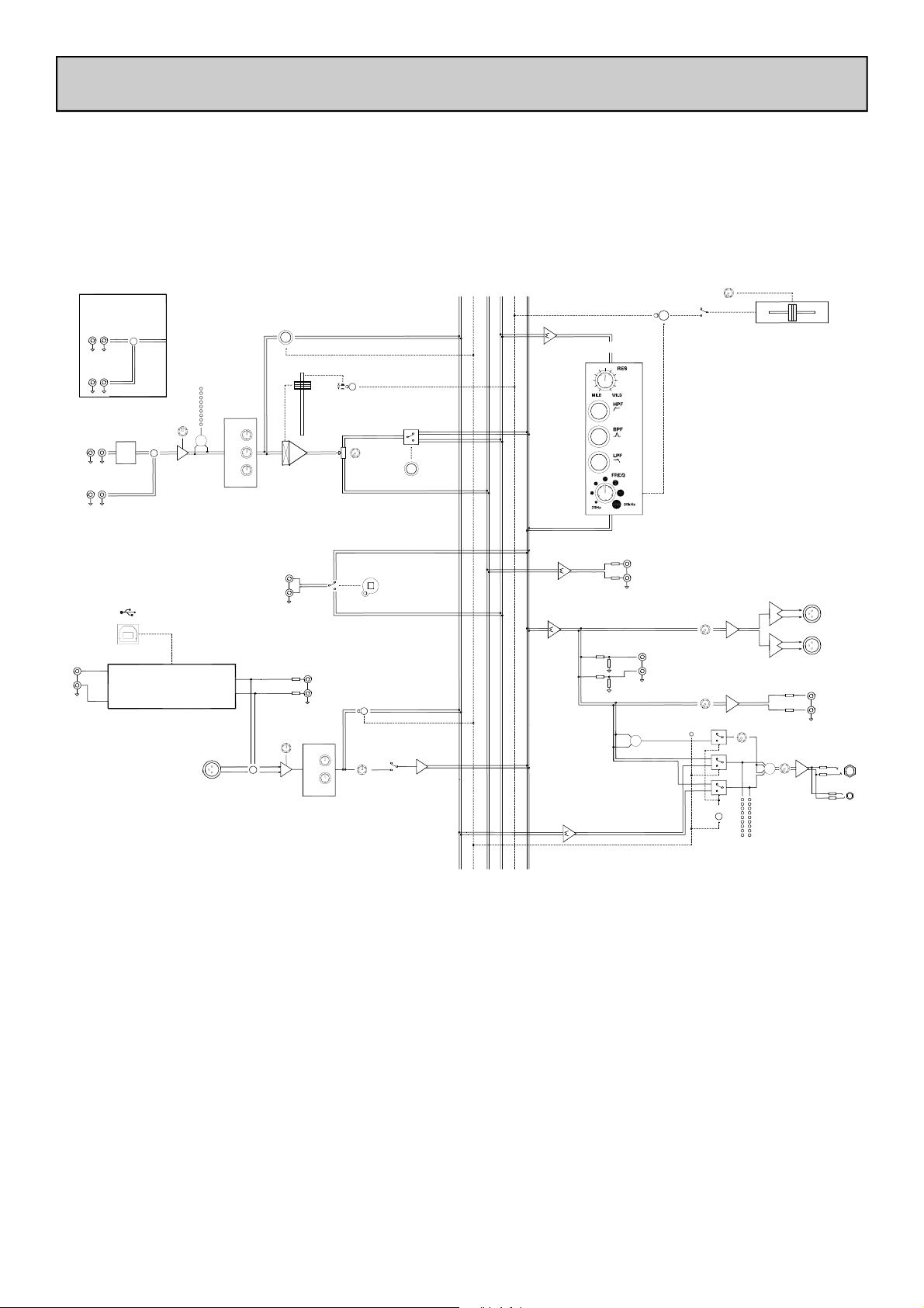
BLOCK DIAGRAM
STEREO INPUTS
LINE A
L
LINE B
L
STEREO INPUTS
PHONO
L
LINE
L
USB AUDIO
USB AUDIO IN
L
R
XONE:42
2 and 3
LINE A/B
R
R
1 and 4
R
RIAA
R
USB
TO PC
USB AUDIO INTERFACE
LEVEL
PHONO/LINE
BLOCK DIAGRAM
CUE
POST-EQ
METER
3 BAND EQ
+
MID
LO
MIC
2= +
MIC INPUT
HI
MIC/USB
FADER
DC
VCA
X:FX RETURN
USB AUDIO OUT
GAIN
+
-
-2dBu
2 BAND EQ
HI
LO
XFADE SELECT
L
R
X:FX
WET/DRY
LEVEL
FILTER
X:FX RETURN
TO FILTER
CH ON
CUE MIX
FILTER MIX
XFADE X/Y DC
CUE LOGIC DC
LR MIX
X:FX SEND
FILTER MIX
VCF TO XFADER
XFADE CURVE
XFADER OFF
CROSSFADER
X
Y
FILTER
DC
X:FX SEND
X:FX SEND
MIX
2=+
LR MIX
CUE MIX
CUE LOGIC DC
RECORD OUT
-10dBV
LR SUM
+
MIX
L
R
BOOTH
CUE ACTIVE
SPLIT CUE
BOOTH
ADD MIX
L
R
LR
CUE PRG - SPLIT
BAL
HEADPHONES
+
METER
L
MIX
+4dBu
OUT
2=+
R
L
BOOTH
R
OUT
PHONES 1/4"
L
R
PHONES 3.5mm
Allen & Heath 8 XONE:42 User Guide
Page 9
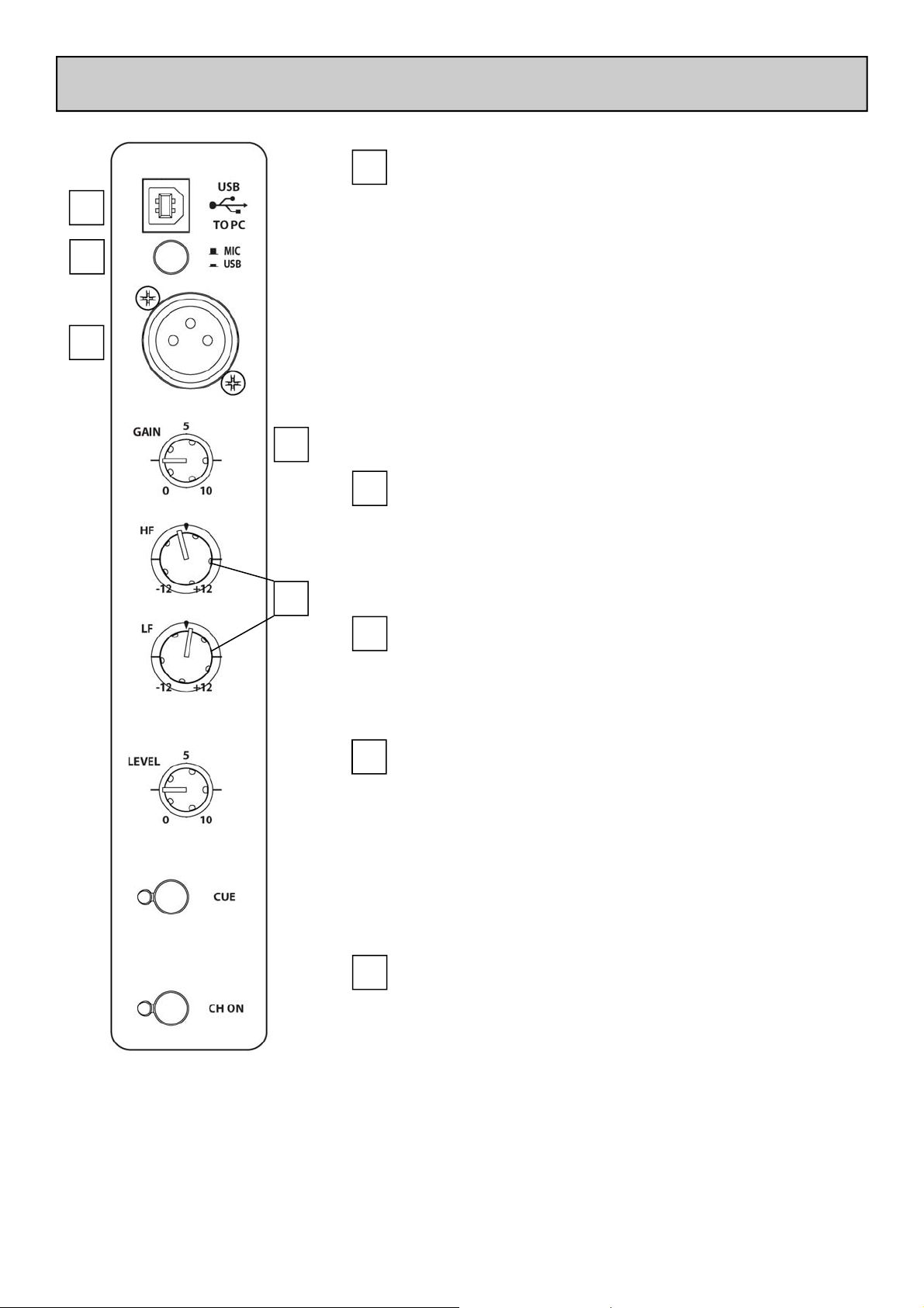
MIC / USB INPUT CHANNEL
1
2
3
4
5
1
2
3
USB Connector
USB (Universal Serial Bus) V1.1 is an external peripheral
interface standard for data transmission. Xone:42 USB
works at 12Mbps and provides two stereo uncompressed audio channels - one stereo up and one stereo
down, or two mono up, two mono down. It is fully
compatible with USB2.
The USB connection is used to send and receive audio
data between the Xone:42 and a connected computer.
Use a standard type A to B lead to connect to your
computer.
Mic / USB Select Switch
Selects either the XLR microphone input or the alternative USB input. In the up position MIC is selected; when
pressed, USB is selected.
Mic Input Socket
Standard 3-Pin XLR socket wired as Pin 1 = Ground, Pin
2 = hot (+), Pin 3 = cold (-).
4
5
Channel Gain Control
This control has a range of -∞dB to +9dB for USB inputs
and a range of –57 dBu to –27dBu for MIC inputs. Use
it to adjust the signal level of an audio source to give a
nominal 0dB reading on the main meters, with the peak
level at or below 6dB. Turn LEVEL down if the +10
peak meter starts flashing.
Channel Equaliser
The Mic/USB input channel is equipped with a 2 band
EQ stage providing +12dB of boost when fully clockwise
and –12dB attenuation when fully anti-clockwise.
Allen & Heath 9 XONE:42 User Guide
Page 10

MIC / USB INPUT CHANNEL
6
7
8
Channel Level Control
The channel signal level can be adjusted from fully off to
fully on.
Cue Switch
Press the Cue switch to listen to the channel pre-fade
signal in the headphones and view its level on the main
meters. The red LED indicator next to the switch lights
when selected. The Cue LED indicator in the monitor
section also lights to warn that you are monitoring the
channel signal rather than the main mix. Press the
switch again to deselect cue.
Channel On Switch
Press the Channel On switch to send the channel audio
to the mix. When selected, the green LED indicator will
illuminate.
6
7
8
Allen & Heath 10 XONE:42 User Guide
Page 11

PHONO / LINE INPUT CHANNELS 1 and 4
1
2
4
5
3
1
2
3
Channel Level Control
This control has a range of off to +10dB. Use it to adjust the signal level of an audio source to give a nominal
0dB reading on the channel meter, with the peak level at
or below 6dB. Turn LEVEL down if the +10 peak meter
starts flashing.
Phono / Line Select Switch
Selects either the RCA phono input or the alternative
RCA stereo line input. In the up position PHONO is
selected; when pressed, LINE is selected.
Channel Equalizer / Isolator
The Xone:42 is equipped with a very powerful 3 band
EQ stage providing a controlled +6dB of boost when
fully clockwise, but full isolation (cut) of each band for
dramatic effect when fully anti-clockwise. Centre
frequencies are set at:
HF = 2.7kHz (high frequency, treble)
MF = 1.2kHz (mid frequency)
LF = 420Hz (low frequency, bass)
4
5
Filter Select
Press this switch to route the channel signal through the
VCF filter. The switch will illuminate to indicate that the
channel is being sent to the filter.
X:FX Dry / Wet Send
Use this control to vary the amount of channel signal
that is sent to an external effects device connected to
the X:FX send / return on the rear panel. With this
control set to ‘dry’, none of the signal is routed to the
external effects loop; if the filter button is illuminated, all
of the channel signal is filtered. With the control in the
central position, half of the signal is sent to external effects, while the other half is unaffected or, if filter is selected, filtered. With the control set to fully ‘wet’, all of
the signal is sent to external effects and the VCF filter is
bypassed.
Allen & Heath 11 XONE:42 User Guide
Page 12

PHONO / LINE INPUT CHANNELS 1 and 4
6
7
Cue Switch
Press the Cue switch to listen to the channel pre-fade
signal in the headphones and see its level on the main
meters. The LED indicator next to the switch lights
when selected. The Cue LED indicator in the monitor
section also lights to warn that you are monitoring the
channel signal rather than the main mix. Press the
switch to deselect cue.
Channel Meter
Displays the channel signal level. It is pre-EQ and prefader, allowing the input level to be displayed even if the
EQ is set to off on all bands. To view the post EQ level,
press the cue switch and use the mix/monitor meters.
The channel level control should be set so that the meter averages around ‘0’ with loudest peaks no higher
than ‘+6’. Turn down the level control if the +10 peak
indicator lights.
6
7
8
8
9
Channel Fader
A high quality, smooth travel dual-rail fader adjusts the
channel signal level from fully off to fully on.
XFade Switch
Used to assign the channel to either the X (left) or Y
(right) side of the cross-fader. Works in conjunction
with the XFADER On switch in the master section.
A bi-colour LED indicator illuminates either green (X)
or red (Y) to show which side of the cross-fader has
been selected.
9
Allen & Heath 12 XONE:42 User Guide
Page 13

LINE / LINE INPUT CHANNELS 2 and 3
1
1
Line A/B Select Switch
Switches between the two RCA stereo line inputs available on Channels 2 and 3. In the up position LINE A is
selected; when pressed, LINE B is selected.
Allen & Heath 13 XONE:42 User Guide
Page 14

FILTER SECTION
1
2
3
4
1
2
3
X:FX Return to Filter
Pressing this button routes the X:FX return to the VCF
filter, instead of directly into the main mix buss. The
effected channel signal can then be filtered as well, allowing extra versatility and creativity to be brought into the
mix. The blue LED lights to indicate that this function is
selected.
Resonance Control
This produces the classic analogue VCF sound by feeding
some of the filter output back to its input. The control
ranges from ‘mild’ producing a very subtle effect, to
‘wild’ producing a dramatic phase effect with feedback
just short of oscillation.
HPF Button
Turns on the high pass (bass cut) filter slope. The light
ring around the button illuminates when selected.
5
4
5
BPF Button
Turns on the band pass (bell shaped) filter slope. The
light ring around the button illuminates when selected.
LPF Button
Turns on the low pass (treble cut) filter slope. The light
ring around the button illuminates when selected.
Allen & Heath 14 XONE:42 User Guide
Page 15

FILTER SECTION
6
7
Frequency Sweep Control
This control sets the –3dB cut-off frequency of the filter.
It ranges from very low frequency (20Hz) to very high
frequency (20kHz).
NOTE: Both BPF and HPF filters are band limited to
prevent them going above 10kHz.
VCF to Crossfader
Press this switch to assign the filter to the crossfader. The
crossfader can then be used instead of the FREQ VCF
sweep control to create filter effects whilst crossfading.
The yellow LED next to the switch illuminates to indicate
that this control is active.
While using the crossfader to sweep the VCF frequencies,
the sweep control ranges from the left-hand (X) side of
the crossfader to the mid-point.
Disabling the crossfader will also disable this function.
6
7
Allen & Heath 15 XONE:42 User Guide
Page 16

HEADPHONE SECTION
1
2
3
4
5
1
2
3
Cue Active LED
This LED lights to indicate that one of more of the input
and / or mic channels is being monitored in the headphones.
Split Cue Switch
Press this switch to change the way Cue operates. Normally, pressing a channel Cue switch overrides both left
and right monitor program signals with the stereo cue
signal. With the switch pressed, Cue overrides just the
left channel leaving the program in the right channel.
The left monitor meter displays the cue signal, right displays program. This is very useful when beat mixing using headphones.
Cue / Mix Control
Allows the main mix output to be added to the Cue signal. Turned fully anticlockwise, only the active Cue is
heard through the headphones when Cue is active.
Gradually turning clockwise introduces the main mix
output to the headphones, together with the active Cue.
Selecting Split Cue will automatically override this control.
4
5
Allen & Heath 16 XONE:42 User Guide
Headphones Level Control
Adjusts the level of the signal in the stereo headphones.
This does not affect the level of the local booth monitor.
Headphone Outputs
Stereo 1/4” TRS jack and 3.5mm mini-jack. Plug in good
quality stereo headphones intended for DJ monitoring.
Use closed-ear headphones that provide maximum
acoustic isolation when cueing your sources. We recommend that you use high quality headphones rated between 30 to 100 ohms impedance. 8 ohm headphones
are not recommended.
Page 17

MASTER SECTION
1
2
1
2
Mix / Monitor Meters
The main meters follow the selected monitor source.
The default display is the post master level, which is
overridden with an input channel level if the channel cue
switch is selected.
In split cue mode, the left master meter will display the
cued channel signal level and the right master meter will
display the mix level. The cued mix audio is pre level to
prevent mismatch due to the position of the master
level control.
The mixer should be operated with these meters averaging around ‘0’ with loudest peaks no higher than ‘+6’.
Mix Master Level Control
A rotary master control adjusts the level of the main
mix XLR outputs feeding the house sound system. This
does not affect the booth output or the meter reading.
3
3
Booth Level Control
Adjusts the level of the signal to the stereo booth RCA
output. This does not affect the headphones. The
booth output could be used for a booth monitor, recording or an additional zone feed.
Allen & Heath 17 XONE:42 User Guide
Page 18

CROSSFADER
2
3
1
Crossfader
1
This lets you fade between signals routed to either side, typically to fade
smoothly into a new music track or to creatively layer sounds when scratch or
cut mixing.
The crossfader is a VCA controller which affects the level of signals routed via
the filters. Make sure the toggle switches on the channels you wish to fade are
set to X or Y as appropriate.
Please contact your Allen and Heath approved service centre for crossfader service or replacement.
Crossfader On Switch
2
In its normal (out) position the crossfader is active. Push the switch to turn the
crossfader off—the channel LED indication will also be switched off.
Crossfader Curve Control
3
This control adjusts the crossfader curve between dipped response, ideal for
seamless beat mixing, and fast-attack, suitable for scratch or cut mixing.
Allen & Heath 18 XONE:42 User Guide
Page 19

REAR CONNECTORS
1 2 3 3 2
CAUTION
WARNING:
FOR CONTINUED PROTECTION AGAINST RISK OF FIRE
REPLACE FUSE WITH SAME TYPE AND RATING.
ATTENTION: REMPLACER PAR UN FUSIBLE
STRICTEMENT IDENTIQUE EN VALEURS.
WARNING: THIS APPARATUS MUST BE EARTHED.
TO REDUCE THE RISK OF FIRE OR ELECTRIC SHOCK
DO NOT EXPOSE APPARATUS TO RAIN OR MOISTURE.
0
OFF
I
ON
SERIAL No:
1
AC Mains Input
IEC cable with moulded mains plug suitable for your local supply.
Important: Read the SAFETY INSTRUCTIONS sheet included with the
Xone:42 and printed on the rear panel.
Check that the correct mains lead with moulded plug has been supplied with your console.
The power supply accepts mains voltages within the range 100-240V without changing any
fuses or settings. Ensure that the IEC mains plug is pressed fully into the rear panel socket
before switching on.
Note: It is standard practice to turn connected power amplifiers down or off before
switching the console on or off. This prevents any potential damage to speaker systems due
to switch-on transients.
LINE
AC MAINS IN ~
100 - 240V~
47-63Hz ~ 30W MAX
INPUT 4
LR
LR
T500mAL 250V 20mm
FUSE
MADE IN THE UK BY ALLEN & HEATH LIMITED
A
LINE
B
INPUT 3
LR
LR
INPUT 2
LRPHONO
LINELINE
A
LINE
LR
B
MIX OUT
LEFT RIGHT
X:FX SND
L
R
LINE
X:FX RTN
L
R
INPUT 1
LRPHONO
LR
L
R
BOOTH
L
R
IN
RECORD
USB AUDIO
LROUT
LR
2
CH 1 and 4 Phono Input
RCA phono 7 –100 mV 47K impedance 380 pF. Plug in turntables with magnetic cartridges
requiring RIAA equalisation. For non-RIAA turntables plug into the LINE input instead. Do
not plug in line level sources to the phono inputs as these will overload the preamp and
cause severe high level distortion.
3
CH 1 and 4 Line Input
RCA phono. Connect stereo line level music sources such as CD, MD, DAT, drum machines, keyboards or other instruments. Do not connect turntables which require RIAA
equalisation. Alternatively, you can connect to jack sources using a cable with RCA to jack
adapters. Avoid using low grade cables such as those often supplied with domestic equipment as these can quickly prove unreliable in use.
Allen & Heath 19 XONE:42 User Guide
Page 20

REAR CONNECTORS
CAUTION
WARNING:
FOR CONTINUED PROTECTION AGAINST RISK OF FIRE
REPLACE FUSE WITH SAME TYPE AND RATING.
ATTENTION: REMPLACER PAR UN FUSIBLE
STRICTEMENT IDENTIQUE EN VALEURS.
WARNING: THIS APPARATUS MUST BE EARTHED.
TO REDUCE THE RISK OF FIRE OR ELECTRIC SHOCK
DO NOT EXPOSE APPARATUS TO RAIN OR MOISTURE.
0
OFF
I
ON
SERIAL No:
4
CH 2 and 3 Line Inputs A/B
RCA phono. Connect stereo line level music sources such as CD, MD, DAT, drum machines, keyboards or other instruments. Switch between inputs A and B using the switches
next to the input levels on the front panel. Do not connect turntables which require RIAA
equalisation. Alternatively, you can connect to jack sources using a cable with RCA to jack
adapters. Avoid using low grade cables such as those often supplied with domestic equipment as these can quickly prove unreliable in use.
LINE
AC MAINS IN ~
100 - 240V~
47-63Hz ~ 30W MAX
INPUT 4
LR
LR
T500mAL 250V 20mm
FUSE
MADE IN THE UK BY ALLEN & HEATH LIMITED
A
LINE
B
INPUT 3
LR
LR
INPUT 2
LRPHONO
LINELINE
A
LINE
LR
B
MIX OUT
LEFT RIGHT
5 4
X:FX SND
L
R
LINE
X:FX RTN
L
R
INPUT 1
LRPHONO
LR
L
R
BOOTH
L
R
6
IN
RECORD
USB AUDIO
LROUT
LR
5
6
Mix Output
Balanced XLR. This is the main output that feeds the house PA system. Plug into the house
processor/amplifier system using balanced cables. Use balanced cables and equipment.
When the main meter LEDs are at “0dB” the output will nominally be at +4dBu. Do not
unbalance this output by shorting one phase to ground—for unbalanced operation use pin 2
only.
USB Audio I/O
RCA phono. Allows external connection to USB interface. The routing is configured for
external input allowing the USB interface to be connected to the insert point and used as an
effects unit with suitable software (such as Ableton Live). To record a mix using the USB In,
connect to the Record Out socket.
The USB interface is compatible with Windows™ 98/98SE, ME, WIN2000 and XP, MAC
OS9.1, OSX (10.0) or later (but not Japanese OS 10.1).
For lowest latency with Windows, an ASIO driver is recommended such as ASIO4ALL by
Michael Tippach — www.asio4all.com
Allen & Heath 20 XONE:42 User Guide
Page 21

REAR CONNECTORS
CAUTION
WARNING:
FOR CONTINUED PROTECTION AGAINST RISK OF FIRE
REPLACE FUSE WITH SAME TYPE AND RATING.
ATTENTION: REMPLACER PAR UN FUSIBLE
STRICTEMENT IDENTIQUE EN VALEURS.
WARNING: THIS APPARATUS MUST BE EARTHED.
TO REDUCE THE RISK OF FIRE OR ELECTRIC SHOCK
DO NOT EXPOSE APPARATUS TO RAIN OR MOISTURE.
0
OFF
I
ON
SERIAL No:
7
X:FX Send/Return
RCA phono. Connect your external effects device and use the X:FX dry / wet control to
send channel signals to the effects unit. The signal returns to the mix buss but can be routed
to the VCF filter by pressing the ‘X:FX Return to Filter’ button on the front panel. This allows the filter to be ‘stacked’ with an external effects device.
LINE
AC MAINS IN ~
100 - 240V~
47-63Hz ~ 30W MAX
INPUT 4
LR
LR
T500mAL 250V 20mm
FUSE
MADE IN THE UK BY ALLEN & HEATH LIMITED
A
LINE
B
INPUT 3
LR
LR
INPUT 2
LRPHONO
LINELINE
A
LINE
LR
B
MIX OUT
LEFT RIGHT
X:FX SND
L
R
LINE
X:FX RTN
L
R
INPUT 1
LRPHONO
LR
L
R
BOOTH
L
R
9 7 8
IN
RECORD
USB AUDIO
LROUT
LR
10
8
9
10
Booth Output
RCA phono (–2dBu nominal). Provides a line level stereo feed to the DJ local monitor amplifier system. It is not affected by the master fader or cue system.
Record Output
RCA Phono, nominal –10dBv (-8dBu). Pre-level mix output for connection to external recording devices.
Chassis Earth Terminal
A screw terminal is provided for connecting the earth straps from turntables. This connection earths the metal parts of the turntable to reduce hum, buzz or similar audible noise getting into the system.
Allen & Heath 21 XONE:42 User Guide
Page 22

USB CONNECTION
The USB interface on the Xone:42 allows connection to a computer for recording, playback, and software-based effects. Remember to always use good quality RCA phono cables to route music signal between devices - sound quality will only be as good as the weakest component in the signal path.
USB for Effects
Connect the X:FX Send to USB In on the left side on the Xone:42’s rear panel using RCA phono cables.
Using a standard Type A to B USB lead, connect the Xone:42 to your computer’s USB port, and start
your chosen FX software. You will need to select ‘USB Audio CODEC’ as the sound playback/recording
device if it is not already selected. Connect USB Out to X:FX Return to complete the effects loop. You
can then use the X:FX dry / wet controls to send signal from each channel to your computer, as you
would with any other external effects hardware.
USB for Playback
Connect your Xone:42 to your computer using a standard Type A to B USB lead. Open your chosen
music playback software, ensuring that ‘USB Audio CODEC’ is selected as the sound playback device.
You can now play music from your computer on the Mic / USB channel; ensure that ‘USB’ is selected using the switch next to the USB port on the Xone:42.
If you wish to apply filter effects, etc. to the music signal from the computer, you can patch the signal into
one of the four stereo channels by simply connecting USB Out to one of the channel Line Inputs.
USB for Recording
Connect your Xone:42 to your computer using a standard Type A to B USB lead. Open your chosen
music recording software, ensuring that ‘USB Audio CODEC’ is selected as the sound recording device.
You can then send your mix to your computer by connecting Record Out to USB In.
USB Audio Levels
You may find that the USB Audio CODEC volume is too quiet when you first connect your Xone:42. To
rectify this, check the device volume in Control Panel\Sounds and Audio Devices:
If the volume is not fully up like this… Then drag it fully up like this…
And click OK
Allen & Heath 22 XONE:42 User Guide
Page 23

FILTER REFERENCE
The VCF Filters
A voltage controlled filter is an audio filter where the cut-off frequency is altered by a DC
control voltage rather than a variable resistor. This produces a much wider operating
range and more control over the filter response to create unlimited combinations of
tonal effect.
Filter Type Select
The filters are ‘state variable’. This means that they provide three simultaneous filter
types: high-pass, band-pass and low-pass. Three large illuminated switches select which
type is active. You can press any combination together to create different response types
such as ‘notch’ and an interesting ‘all-pass’ effect. The switches are ‘soft switched’ for live
performance, meaning that the audio signal is ramped between filter states to prevent
audible clicks.
Note that the last selected type is lost when power is removed from the console. The
LPF is always selected when power is applied.
The graphs below show the effect on the audio frequency response for the three filter
types. The range of sweep from low to high frequency is shown together with the effect
of adjusting RESONANCE (one frequency with several resonance settings shown).
The vertical scale shows the amount of cut or boost around the normal 0dB operating
level. The horizontal scale shows the change in frequency from low (bass) to high
(treble).
+20
+15
+10
+5
0dB
-5
-10
-15
-20
+20
HI-PASS FILTER
LO
LO-PASS FILTER
HI
10k20 1kHz100 20k
+20
+15
+10
+5
0dB
-5
BAND-PASS FILTER
LO
HI
+15
+10
+5
0dB
-5
-10
-15
-20
LO
HI
10k20 1kHz100 20k
-10
-15
-20
10k20 1kHz100 20k
Allen & Heath 23 XONE:42 User Guide
Page 24

OPERATING LEVELS
It is most important that the system level settings are correctly set. It is well known that
many DJs push the level to maximum with meters peaking hard in the belief that they are
getting the best from the system. THIS IS NOT THE CASE ! The best can only be
achieved if the system levels are set within the normal operating range and not allowed to
peak. Peaking simply results in signal distortion, not more volume. It is the specification of
the amplifier / speaker system that sets the maximum volume that can be achieved, not the
console. The human ear too can fool the operator into believing that more volume is
needed. Be careful as this is in fact a warning that hearing damage will result if high listening levels are maintained. Remember that it is the QUALITY of the sound that pleases the
ear, not the VOLUME.
The diagram below illustrates the operating range of the audio signal.
NORMAL OPERATING RANGE. For normal music the signal should range between
–6 and +6 on the meters with average around 0dB. This allows enough HEADROOM for
unexpected peaks before the signal hits its maximum CLIPPING voltage and distorts.
It also achieves the best SIGNAL-TO-NOISE-RATIO by keeping the signal well above
the residual NOISE FLOOR (system hiss).
The DYNAMIC RANGE is the maximum signal swing available between the residual
noise floor and clipping.
An important note …
82!
Allen & Heath 24 XONE:42 User Guide
The human ear is a remarkable organ with the ability to compress or ‘shut down’ when sound levels become too high. Do
not interpret this natural response as a reason to turn the system volume up further ! As the session wears on ear fatigue
may set in, and the speaker cones may become hot so reducing
the effectiveness of the system and listeners to gain any benefit
from increased volume.
Page 25

EARTHING
The connection to earth (ground) in an audio system is important for
two reasons:
SAFETY - To protect the operator from high voltage electric shock,
and
AUDIO PERFORMANCE - To minimise the effect of earth (ground)
loops which result in audible hum and buzz, and to shield the audio
signals from interference.
For safety it is important that all equipment earths are connected to
mains earth so that exposed metal parts are prevented from carrying
high voltage which can injure or even kill the operator. It is
recommended that a qualified system engineer check the continuity of
the safety earth from all points in the system including microphone
bodies, turntable chassis, equipment cases, and so on.
The same earth is also used to shield audio cables from external
interference such as the hum fields associated with power transformers,
lighting dimmer buzz, and computer radiation. Problems arise when the
signal sees more than one path to mains earth. An ‘earth loop’ (ground
loop) results causing current to flow between the different earth paths.
This condition is usually detected as a mains frequency audible hum or
buzz.
To ensure safe and trouble-free operation we recommend the following:
Have your mains system checked by a qualified electrician. If
the supply earthing is solid to start with you are less likely to experience
problems.
Do not remove the earth connection from the console mains
plug. The console chassis is connected to mains earth through the
power cable to ensure your safety. Audio 0V is connected to the
console chassis internally. If problems are encountered with earth loops
operate the audio ‘ground lift’ switches on connected equipment
accordingly, or disconnect the cable screens at one end, usually at the
destination.
Make sure that turntables are correctly earthed. A chassis earth
terminal is provided on the console rear panel to connect to turntable
earth straps.
Use low impedance sources such as microphones and line level
equipment rated at 200 ohms or less to reduce susceptibility to
interference. The console outputs are designed to operate at very low
impedance to minimise interference problems.
Use balanced connections for microphones and mix output as
these provide further immunity by cancelling out interference that may
be picked up on long cable runs. To connect an unbalanced source to a
balanced console input, link the cold input (XLR pin 3 or jack ring) to 0V
earth (XLR pin 1 or jack sleeve) at the console. To connect a balanced
XLR output to unbalanced equipment, link the cold output to 0V earth
at the console.
Use good quality cables and connectors and check for correct
wiring and reliable solder joints. Allow sufficient cable loop to prevent
damage through stretching.
If you are not sure ... Contact your service agent or local Allen &
Heath dealer for advice.
Allen & Heath 25 XONE:42 User Guide
Page 26

REPLACING THE CROSSFADER / FACE PLATE
Replacing the Crossfader
− Firstly, pull the crossfader cap vertically off the fader shaft and put it somewhere sensible.
− Use a medium size cross-point screwdriver to undo and remove the two outer screws on the
crossfader plate.
− Carefully pull the crossfader assembly away from the front panel.
− Unplug the cable from the old crossfader, and once the crossfader assembly is detached, un-
screw the two inner screws to separate the fader from the plate.
− Fit the new crossfader, put the inner screws back in, and re-connect the cable.
− Check that the connector is correctly aligned and pushed on.
− Replace the assembly making sure the cable faces the right-hand side of the console.
− Refit the outer screws and test operation.
Standard Alpha Crossfader Part Number— 003-829 JIT
Penny & Giles Crossfader Option Part Number— 002-719 JIT
Allen & Heath 26 XONE:42 User Guide
Page 27

AB3819 M3x5 CSK S/S (12 places faders - marked here with ‘+’)
AJ5558 X-FADE
ADJUST KNOB
*
*
USER-REPLACEABLE PARTS
AJ5320 XONE FADER KNOB (5 places - faders)
AJ4251 PUSH BUTTON
ROUND BK 8MM (14 places)
AJ5324 LIGHT PIPE (11 places)
*
+
+
+
*
+
+
*
+
+
+
+
+
*
+
AJ7304 XONE EQ KNOB
(SML) (20 places)
AJ7305 XONE GAIN
KNOB (LGE) (10 places)
AB2810 4x5/16 PAN
BK (2 places - XLR)
AJ5325 FILTER / CUE
BTN (11 places)
AJ3488 PUSH BUTTON
SQUARE RED 5MM
AB8172 POT NUT BK (30 places under knobs)
AB3820 M3x8 CSK S/S (10 places - front
panel - marked here with ‘*’)
+
*
*
AB2771 4x5/16 PAN BK
PLASTITE (9 places - RCAs)
AB2810 4x5/16 PAN BK (4 places - XLRs)
AL3534 FUSE 500mA
AB0076 M3x10 PAN BK (2 places - IEC plug)
AJ2887 PUSH BUTTON BK (PSU)
*
*
AB8106 CHASSIS
GROUND POST
The diagram above shows all of the replacement parts that can be ordered from your local
technical support, or direct from Allen & Heath, for the Xone:42. When ordering please
quote the part number(s) of the required parts - this makes life easier for us!
Note: Key for front panel screws
Screws marked with ‘*’ on the above diagram are the M3x8 stainless steel countersunk type,
which require a T10 ‘Torx’ screwdriver. Screws marked with ‘+’ are the shorter M3x5
stainless steel countersunk fader screws, which require a medium size cross-point screwdriver.
See the previous page for information on replacing the crossfader, and for replacement crossfader assembly numbers.
Allen & Heath 27 XONE:42 User Guide
Page 28

Check out the website:
www.xone.co.uk
… for products, news, reviews, user forum, downloads, galleries, merchandise, and much more ...
Allen & Heath 28 XONE:42 User Guide
 Loading...