

Page 1
P R O F E S S I O N A L D J M I X E R
USER GUIDE
Publication AP4264
Page 2

Limited One Year Warranty
This product is warranted to be free from defects in materials or workmanship for a period of
one year from the date of purchase by the original owner.
To ensure a high level of performance and reliability for which this equipment has been
designed and manufactured, read this User Guide before operating.
In the event of a failure, notify and return the defective unit to ALLEN & HEATH or its
authorised agent as soon as possible for repair under warranty subject to the following
conditions
Conditions Of Warranty
1. The equipment has been installed and operated in accordance with the instructions in
this User Guide
2. The equipment h as not been subject to misuse either intended or accidental, neglect, or
alteration other than as described in the User Guide or Service Manual, or approved by
ALLEN & HEATH.
3. Any necessary adjustment, alteration or repair has been carried out by ALLEN &
HEATH or its authorised agent.
4. This warranty does not cover crossfader wear and tear.
5. The defective unit is to be returned carriage prepaid to ALLEN & HEATH or its
authorised agent with proof of purchase.
6. Units returned should be packed to avoid transit damage.
In certain territories the terms may vary. Check with your ALLEN & HEATH agent for any
additional warranty which may apply.
This product complies with the European Electromagnetic Compatibility
directives 89/336/EEC & 92/31/EEC and the European Low Voltage
Directives 73/23/EEC & 93/68/EEC.
This product has been tested to EN55103 Parts 1 & 2 1996 for use in Environments E1,
E2, E3, and E4 to demonstrate compliance with the protection requirements in the
European EMC directive 89/336/EEC. During some tests the specified performance
figures of the product were affected. This is considered permissible and the product has
been passed as acceptable for its intended use.
Allen & Heath has a strict policy of ensuring all products are tested to the latest safety
and EMC standards. Customers requiring more information about EMC and safety
issues can contact Allen & Heath.
NOTE: Any changes or modifications to the console not approved by Allen & Heath
could void the compliance of the console and therefore the users authority to operate it.
XONE:32 User Guide AP4264 Issue 6
Copyright © 2004 Allen & Heath Limited. All rights reserved
Allen & Heath Limited
Kernick Industrial Estate, Penryn, Cornwall, TR10 9LU, UK
http://www.allen-heath.com
2 XONE:32 User Guide
Page 3
Important Safety Instructions – Read First
Read instructions: Retain these safety and operating instructions for future reference. Adhere to all
warnings printed here and on the console. Follow the operating instructions printed in
this User Guide.
Do not open: Operate the console with its front and crossfader panels correctly fitted. Disconnect
mains power by unplugging the power cord if a panel needs to be removed for
servicing. Refer this work to competent technical personnel only.
Power sources: Connect the console to a mains power only of the type described in this User Guide and
marked on the rear panel. The power source must provide a good ground connection.
Power cord: Use the power cord with sealed mains plug appropriate for your local mains supply as
provided with the console. If the provided plug does not fit into your outlet consult your
service agent for assistance. Route the power cord so that it is not likely to be walked
on, stretched or pinched by items placed upon or against it.
Grounding: Do not defeat the grounding and polarisation means of the power cord plug. Do not
remove or tamper with the ground connection in the power cord.
Ventilation: Do not obstruct the ventilation slots or position the console where the air flow required
for ventilation is impeded. If the console is to be operated in a rack unit or flightcase
ensure that it is constructed to allow adequate ventilation.
Moisture: To reduce the risk of fire or electric shock do not expose the console to rain or moisture
or use it in damp or wet conditions. Do not place containers of liquids on it which might
spill into any openings.
Heat: Do not locate the console in a place subject to excessive heat or direct sunlight as this
could be a fire hazard. Locate the console away from any equipment which produces
heat such as power supplies, power amplifiers and heaters.
Environment: Protect from excessive dirt, dust, heat and vibration when operating and storing. Avoid
tobacco ash, drinks spillage, and smoke, especially that associated with smoke
machines.
Handling: To prevent damage to the controls and cosmetics avoid placing heavy objects on the
control surface, scratching the surface with sharp objects, or rough handling and
vibration. Protect the controls from damage during transit. Use adequate packing if you
need to ship the unit.
Servicing: Switch off the equipment and unplug the power cord immediately if it is exposed to
moisture, spilled liquid, objects fallen into the openings, the power cord or plug become
damaged, during lightening storms, or if smoke, odour or noise is noticed. Refer
servicing to qualified technical personnel only.
Installation: Install the console in accordance with the instructions printed in this User Guide. Do not
connect the output of power amplifiers directly to the console. Use audio connectors
and plugs only for their intended purpose.
Important Mains Plug Wiring Instructions
The console is supplied with a moulded mains plug fitted to the AC mains power lead.
Follow the instructions below if the mains plug has to be replaced.
The wire which is coloured Green/Yellow or Green must be connected to the terminal in
the plug which is marked with the letter E or with the Earth symbol.
This appliance must be earthed.
The wire which is coloured Blue or White must be connected to the terminal in the plug
which is marked with the letter N.
The wire which is coloured Brown or Black must be connected to the terminal in the
plug which is marked with the letter L.
Ensure that these colour codes are followed carefully in the event of the plug being
changed.
XONE:32 User Guide 3
Page 4

Contents
Important Safety Instructions ................ 3
Introduction ........................................... 4
Quick Start............................................. 5
Connectors and Panel Controls ........... 6
Installation ........................................... 10
Cable diagrams ................................... 11
Introduction
Welcome to the XONE:32 professional DJ mixer. This stylish and solidly built 3 channel club format console
presents a unique combination of performance tools for the professional DJ. Above all, it features a sound
quality second to none. XONE:32 has been designed and constructed using the same rigorous standards we
apply to our large format professional consoles used and respected by top engineers and performers throughout
the world. We have had great fun designing this new range. We are sure you will get even more enjoyment
using it.
We know you want to get started right away. For this reason we have kept this user guide concise and to the
point. We recommend you read it through first. However, if even that is too much then at least read the QUICK
START page before you plug up and go.
This user guide refers to the XONE:32. For further information on the basic principles of audio system
engineering and mixing technique please refer to one of the specialist publications available from bookshops
and audio equipment dealers. Whilst we believe the information in this guide to be reliable we do not assume
responsibility for inaccuracies. We also reserve the right to make changes in the interest of further product
development.
We are able to offer further product support through our world-wide network of approved deale rs and service
agents. You can also access our Web site on the Internet for information on our product range, assistance with
your technical queries or simply to chat about matters audio. To help us provide the most efficient service
please keep a record of your console serial number, and date and place of purchase to be quoted in any
communication regarding this product.
Operating Instructions .........................12
Replacing the Crossfader....................14
Specification ........................................18
Glossary...............................................20
Order Codes ........................................ 22
Tips and Troubleshooting ...................23
Check out our home site
full product range and our design philosophy. We also have a site dedicated to the exciting XONE console
range
www.xone.co.uk.
Key Features
• 3 Stereo channels with switchable line and RIAA phono inputs
• DJ microphone input
• Separate main mix, record, booth and headphones monitor outputs
• Stereo Aux output for effects
• 3 Band +6/-26 asymmetric EQ with extended cut
• Removable VCA CROSSFADER with reverse and variable contour
• Crossfade position dependent TRANSMUTE buttons for transform and punch effects
• Analogue state variable VCF filter effects with filter type, frequency and resonance controls
• LFO filter frequency control with finger tap tempo select
• DRS™ Digital Recall System with 4 user programmable presets for filter effects
• Advanced cue system with interlock and cue/mix fader for performance preview
• Extensive channel and output metering
• Sensible layout of setup and performance controls across three surfaces
• High grade dual rail gold contact crossfader
• Universal internal power supply for any worldwide mains voltage
www.allen-heath.com for information on the company and its pedigree, our
4 XONE:32 User Guide
Page 5
Quick Start
1 Ensure your safet y Mains voltage is dangerous and can kill. First read and understand the Important
Safety Instructions printed on page 3. Make sure that all equipment in your system is set for your local mains
supply voltage and correctly grounded to ensure your safety. Do not turn anything on until you have checked
your system wiring and control settings.
2 Set all controls to their starting position Set all FADERS, GAIN, AUX, RESONANCE, HEADPHONES,
BOOTH and MAIN MIX controls minimum (anti-clockwise). Set BAL, EQ and CONTOUR controls to their centre
position. Set CROSSFADER to X (left), VCF slider to 20kHz (right) and CUE/MIX slider to cue (left). Set all
switches to their up position.
3 Plug in your sources and outputs Plug in two music sources, one to CH1 (X) the other CH3 (Y). Select
the rear panel switches according to line or RIAA turntable source. Plug in your microphone if you are using
one. We recommend you use a cardiod vocal dynamic type with built-in on/off switch. Plug the MIX OUT into
the amplifiers feeding the main speakers, the BOOTH OUT into the amplifiers feeding the local DJ speakers,
and plug in your stereo headphones. Good quality headphones of around 70 ohms impedance are
recommended. It is very important that the amplifier level controls are turned right down at this stage.
4 Tur n the system on Switch on the mixer and music sources first. Check that the CH1 CU E, filter LPF
and CROSSFADE ON indicators are on, the rest off. The LFO ON indicator should be flashing very slowly.
Then switch on the amplifiers with their level controls turned down. The system should be quiet. If you hear
any hum or buzz check the system for bad wiring, ground loops or missing grounds, in particular those
connecting to turntables.
5 Adjust the level trims and cue the chan nels Start the music playing and raise the LEVEL trim for eac h
channel until its meter reads an average ‘0’ with loud moments at ‘+5’. If the red ‘PEAK’ indicator flashes then
back off the trim slightly. Slowly raise the headphones level control. You should hear CH1 CUE feeding the
signal with the CUE/MIX fader set fully left for cue only. Press CH3 CUE to check the CH3 signal. If the music
sounds distorted, bassy or thin check that you have plugged it into the correct Line or Phono inputs.
6 Route the music to the main speakers With music playing and crossfader set to left hand X position,
raise the CH1 fader to its top ‘0’ position. Next, raise the MAIN MIX rotary master to maximum and check that
the main meters display the music level. These should average ‘0’ with loudest moments up to ‘+5’. If the red
PEAK indicator flashes then back off the channel gain. Now slowly raise the amplifier level trim. You should
start to hear the music through the main speakers. Set the amplifiers for the loudest volume you want to allow
in the room with console meters reading as described above. If you are using a microphone then switch it on
and raise its GAIN control until you hear it in the mix. Turn back the gain if the mic starts to feed back.
7 Route the music to the booth monitor speakers Now set the BOOTH level rotary to maximum and
slowly turn up the booth amplifier level trim until the monitor is as loud as you need it to be. Setting the levels in
this way prevents the DJ exceeding the allowed maximum by setting all the console faders and masters to
maximum. The meters provide an accurate display of the system capability. Access to the rear panel level trim
controls can be restricted by covering them if needed.
8 Experiment with the level and crossfader controls With two music sources playing (CH1=X, CH2=Y)
you can experiment with these important performance controls. Adjust the crossfade CONTOUR from a gentle
fade to very steep cut suitable for fast scratch mixing. You can reverse X and Y to suit your mixing style, and
turn the crossfader off if it is not required. The TRANSMUTE button allows fast performance effects,
transforming (muting) the signal if the crossfader is on its side, or punching the signal in if the crossfader is on
the opposite side. Also experiment with the small CUE/MIX fader which lets you preview your mix in the
headphones first.
9 Experiment with the EQ, VCF and LFO effects Now the creative fun bit. With one channel playing,
listen to the effect of cutting or boosting the three EQ controls. Press the channel FILTER switch to enable the
VCF, experimenting with the FREQUENCY slider, RESONANCE and HPF/BPF/LPF type controls to change
the sound. You can create subtle or dramatically sweeping effects. Watch the meters and pull back the fade r if
necessary to ensure you do not exceed the maximum volume allowed. Turn the LFO on and set its speed by
tapping the TEMPO button. The VCF slider now becomes a depth control for LFO to modulate the VCF.
10 Store and recall the user presets Once you have a VCF/LFO effect you like you can store this as a
user preset to be instantly recalled during performance. Simply press and hold the required pres et button for
longer than 2 seconds to store the settings. Tap the button to recall a preset. The preset remembers the VCF
and LFO settings as well as which channels are assigned to the filter.
Important Note about Hearing : To avoid damage to your hearing do
not operate any sound system at excessively high volume. This also applies to any
close-to-ear monitoring such as headphones. Continued exposure to high volume
82!
XONE:32 User Guide 5
sound can cause frequency selective or wide range hearing loss. Make sure that your
system complies with any venue sound level and noise regulations which may apply.
Page 6
AVIS: RISQUE DE CHOC ELECTR IQUE - NE PAS OUVRIR.
100 - 240V~
47-63Hz ~ 30W MAX
DRS DIGITAL RECALL SYSTEM
P R O F E S S I O N A L D J M I X E R
P R O F E S S I O N A L D J M I X E R
6 XONE:32 User Guide
Page 7
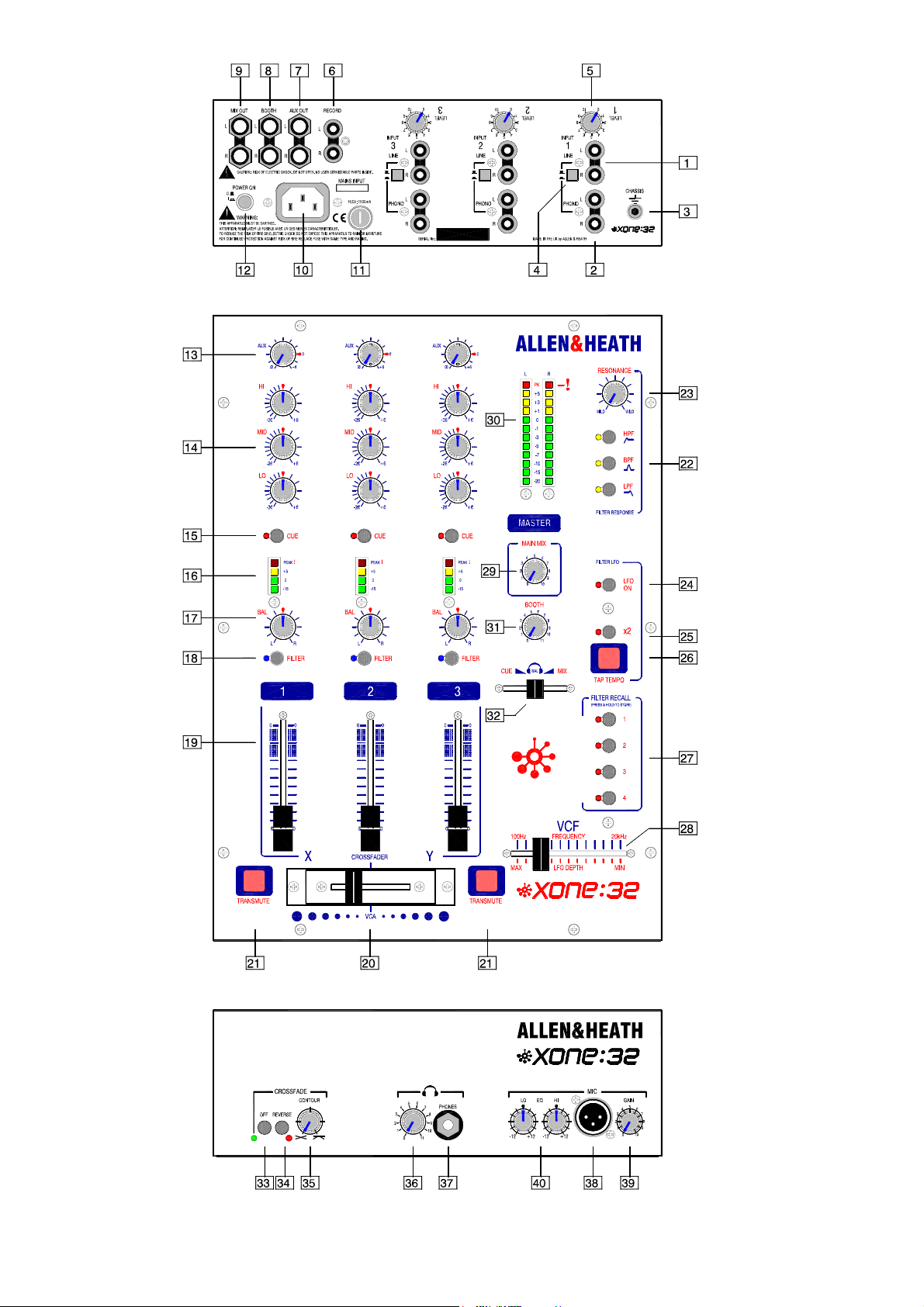
Connectors and Panel Controls
1 LINE input 2x RCA phono. Connect stereo line level music sources such as CD, MD, DAT, drum
machines, keyboards or other instruments. Do not connect turntables which require RIAA equalisation.
2 PHONO input 2x RCA phono. Plug in turntables with magnetic cartridges requiring RIAA equalisation.
For non-RIAA turntables plug into the LINE input instead. Do not plug in line level sources to the phono inputs
as these will overload the preamp and cause severe high level distortion.
3 CHASSIS earth A screw terminal is provided for connecting the earth straps from turntables. This
connection earths the metal parts of the turntable to reduce hum, buzz or similar audible noise getting into the
system. Make sure the terminal is fully tightened once the strap is in place.
4 INPUT SELECT switch Selects either the LINE input or the PHONO input as the source to the channel.
Press for PHONO, release for LINE. The select switches are positioned on the rear panel to prevent accidental
operation during performance.
5 INPUT LEVEL trim Rotary control to adjust the input gain to match the connected source to the console
operating level. Adjusts from fully off to +15dB gain. Use the channel meter 16 to ensure the trim is correctly
set for best performance. The trims are positioned on the rear panel so that they are protected from accidental
operation once set.
6 RECORD output 2x RCA phono. This provides a line level stereo mix output not affected by the main
mix master control. Connect to a stereo recorder such as MD, DAT or cassette to record the DJ’s set.
7 AUX o u t p u t 2x TRS jack. Provides a line level stereo output independently mixed from the channel AUX
sends 13 . You can use this to feed samplers and othe r effects units, an additiona l monitor, zone or recorder .
The output is impedance balanced so it can connect to balanced or unbalanced equipment.
8 BOOTH output 2x TRS jack. This is the stereo output that feeds the DJ’s local booth monitor system. It
has its own level control and is not affected by the main mix master control or the cue mix. The output is
impedance balanced so it can connect to balanced or unbalanced equipment.
9 MIX output 2x TRS jack. This is the main stereo output that feeds the house PA. The output is
electronically balanced so it can drive long cable runs to balanced equipment without interference pickup. It can
also be wired to connect to unbalanced equipment.
10 M AINS input IEC socket. Plug the AC mains supply in here. A country dependent mains lead with
moulded plug is provided with the console. Ensure the local mains voltage is within the range specified on
the panel and that the connection is correctly grounded.
11 FUSE This is the mains input protection fuse for the internal power supply. In the unlikely event of it
failing make sure you replace it with the same type and rating. If the replacement fails get the console checked
by your service agent.
12 POWER ON switch Turns the console on or off. To avoid loud thumps or damage to your speakers
always turn amplifiers off before turning the console or other equipment in the signal chain on or off. Turn
amplifiers on last and off first.
13 AUX SEND control Adjusts the level of the channel signal to the stereo Aux output. It is taken ‘post-fade’
which means that the channel fader affects the level sent to the aux control. Turn fully anticlockwise to turn the
signal off, fully clockwise for a maximum +6dB boost. The normal ‘0’ position is marked.
14 Channel EQ The equaliser has three controls to let the DJ creatively alter and shape the sound during
live performance. The music frequency spectrum is divided into 3 bands. HI (10kHZ) has a shelving response
and affects the high frequency (treble) sounds, MID (1kHz) has a peak/dip bell shaped response and affects mid
range (presence) sounds, and LO (100Hz) has a peak/dip bell shaped response and affects lo w (bass) sounds.
This type of equaliser is known as ‘asymmetric’ because the amount of boost and cut is not the same. Boost is
restricted to a safe +6dB to highlight selected sounds while preventing system overload through heavy use. Cut
on the other hand, is increased to a huge –26dB to completely suck out affected frequencies dramatically
changing the effect. Use cut rather than boost to create your dramatic performance effects.
15 CUE switch Press this momentary switch to listen to the channel signal in the headphones. The three
switches are interlocked so that pressing one or more cancels the previous. The LED illuminates so that you
can see at a glance which channel is cued. A cue selection is always active. Switch on default is CH1 cue
selected. You can preview the mix using the CUE/MIX slider 32 . Cue does not affect the house mix or booth
speakers and lets you check the signal or cue a track before bringing it into the mix. Cue is pre-fader and postEQ so that you can preview and experiment with the EQ effects before going live.
16 Channel METER A 4 LED meter bar al ways shows the presence of the pre-fa der channel signal. Adjust
the level trim control for normal music averaging 0dB with loudest moments reaching +5. Reduce the trim if the
red PEAK LED flashes consistently. The PEAK LED lights at +8dB to warn that you are within 12dB of clipping.
Letting the signal clip will result in a harsh distorted sound that can damage the speakers and is very unpleasant
for the listener. A good DJ will not let this happen.
XONE:32 User Guide 7
Page 8
17 BALANCE control Adjusts the balance between the channel left and right stereo signals. Each side
ranges from fully off to fully on. The control has unity gain in the centre equal position and +2dB boost when
fully panned to one side. It is typically used for performance effect.
18 FI LTER ON switch Press this momentary switch to route the channel through the filter stage for amazing
analogue VCF (voltage controlled filter) effects. The blue LED lights when the VCF is enabled for the channel.
The state of the switch is stored and recalled by the DRS™ presets.
19 Channel FADER A high grade 60mm stereo fader adjusts t he channel signal level from off to the normal
‘0’ top position. It allows smooth fade ins and quick action live performance level effects. CH1 fader routes the
signal to the X side of the crossfader. CH3 routes the signal to the Y side of the crossfader. CH2 does no t
route through the crossfader. The fader also affects the AUX sends 13 .
20 CROSSFADER The crossfader lets you smoothly fade from one track into another using a single fader.
It is also used as a creative performance tool to layer or interact between two sounds when cut or scratch
mixing. It can be easily replaced if it becomes damaged or worn through exceptional mechanical operation.
Long life is assured as the XONE:32 uses a high quality dual rail gold contact crossfade type together with VCA
circuitry which means that no audio is passed through the fader itself. CH1 routes to X, CH3 routes to Y, CH2
does not route through the crossfader. The response of the crossfader can be adjusted to match your mixing
style using the CONTOUR and REVERSE controls 35 .
21 TRANSMUTE buttons The XONE:32 introduces this unique function which combines the familiar
‘transform’ and ‘punch’ DJ effects with an intelligence that opens up a new world of creative live performance
effects. The function of the button depends on the position of the crossfader. TRANSMUTE becomes a
transform
mute that turns the signal off while the button is held. TRANSMUTE becomes a punch
crossfader is right at the opposite side playing the other track. Here it punches the signal in (turns it on) on top
of the other track. For example, the CH1 track may be playing… Pressing X TRANSMUTE transforms (mutes)
that track, and pressing Y TRANSMUTE punches the CH3 track over the CH1 track.
button when the crossfade has moved away from the opposite side. It acts as a momentary action
button when the
22 VCF Filter Type Select Press one or any combination of the three momentary press buttons to select the
VCF response type. Default on power up is LPF (low pass filter) which cuts off all frequencies above the
selected frequency. Alternatively, you can select BPF (band pass filter) to cut off frequencies above and below,
or HPF (high pass filter) to cut off frequencies below, or press two or three buttons together to create different
effects. One or more types is always selected. The associated LED indicator is illuminated. The selected type
is stored and recalled by the DRS™ presets.
23 RESONANCE control Adjust this to change the ‘Q’ or ‘sharpness’ of the filters. This affects how they
respond around the cut-off frequency. At the minimum MILD setting the filters have a gentle roll-off ‘knee’ giving
a subtle, smooth response. At the clockwise WILD setting they produce a resonant feedback boost around cutoff resulting in some very dramatic performance effects. The sound varies according to the filter type selected.
To avoid unexpected results it is best to start experimenting with RESONANCE set to a low (mild) position.
24 LFO ON sw itch Press this momentary switch to let the LFO (low frequency oscillator) take over control of
the VCF by modulating its cut-off frequency. The LED indicator always flashes green to display the currently set
speed. It turns red when the LFO is switched in and continues to flash green to indicate speed. The V CF
FREQUENCY slider 28 changes function to become a depth control to determine how much modulation is
applied. The state of this switch is stored and recalled by the DRS™ presets.
25 x2 switch Doubles the speed of the LFO as set by tapping in the tempo. This lets you tap in the beat of
the track and create a double modulation per beat. The state of this switch is stored and recalled by the DRS™
presets.
26 TAP TEMPO button Tap this button with your finger to set the speed of the LFO. It automatically follows
your beat after two or three taps. You can double the speed by pressing the x2 switch 25 .
27 FILTER RECALL (DRS™ presets) This feature unique to Allen & Heath provides 4 preset buttons whic h
lets you store and recall your favourite VCF performance settings. This lets you punch in sophisticated filter
effects changes. When you first turn the console on there are no presets stored or recalled. Pre ss and hold
one of the preset buttons for longer than 2 seconds to store the current settings into that memory. Tap the
button during performance to instantly recall that preset. The presets do not store the VCF resonance,
frequency, LFO depth or speed. The parameters stored include:
• CH1-3 FILTER ON switch – Which channels have the VCF enabled
• VCF type – Which combination of HPF, BPF and LPF is active
• LFO ON switch – Whether the VCF is manually controlled or modulated by the LFO
• LFO x2 switch – Whether the LFO speed is 1x or 2x the current speed
8 XONE:32 User Guide
Page 9

28 VCF contr ol slider This is a performance control ‘played’ by the DJ to create live effects in a similar wa y
to using the crossfader. Its function depends on whether the LFO is switched on or off. If the LFO is off then
the slider lets you manually set the cut-off frequency of the filter from a very low 100Hz to ultra high 20kHz. If
the LFO is switched on then the slider becomes a depth control for the LFO letting you adjust how much the
LFO modulates the filter cut-off frequency. Depth is off when the slider is fully right. Maximum effect is fully left
as the DJ pulls the slider in towards the other performance controls.
29 MAIN MIX MASTER control A rotary master control adjusts the output level feeding the house PA. This
is a stereo control which adjusts the left and right signals at the same time. It affects the stereo MIX output.
Note that it does not affect the record and booth outputs. The maximum position represents unity (0dB) gain. If
you find yourself normally setting the control in the lower part of its travel then the connected equipment may be
too sensitive for the operating level of the console. With the control set to its maximum position adjust the input
level trim of connected equipment for the loudest level allowed. In a club or similar installation strict sound
level and noise regulations may apply. Check that your system levels are set up to comply.
30 MAIN METERS A pair of LED meter bars displays the level of the MAIN MIX output. Each meter has 12
LEDs to indicate signal levels from a low –20dB. Green and yellow LEDs indicate normal operating levels. The
top red PEAK led lights at +8dB giving you plenty of warning that you are within 12dB of clipping. Meter ‘0’
represents +4dBu at the XLR outputs. The meters are peak responding with a fast attack and are therefore
able to display fast transients accurately. The top five LEDs are ‘peak hold’ which means that the highest
remains lit for a short time after the signal has gone. This makes it easier to keep track of the highest levels and
transient peaks. Do not operate the console with these meters lighting red more than the occasional
flash. Failure to observe this can result in severe signal distortion which may damage equipment.
31 BOOTH MASTE R control Adjusts the level of the signal to the stereo booth monitor output. This does
not affect the level in the headphones.
32 CUE/MIX slider This affects what you hear in the headphones. When fully left, only the CUE signal is
routed. The CH1, 2 and 3 CUE switches are interlocked with a selection always active. When fully right, the
main MIX is routed so you hear only what is being sent to the house speakers. Mo ve the slider between these
positions to mix the active CUE signal with the MIX. This not only lets you use the headphones to cue tracks
ready to bring them into the mix, but also accurately adjust point and tempo again st the currently playing track
and preview how the mix will sound. You use this slider as a ‘crossfader’ to test the mix in your headphones
only. It does not affect the booth or house mix.
33 CROSSFADE OFF switch This front panel switch lets you disable the crossfader so that the channels
route directly to the main mix. The green LED lights when the crossfader is enabled.
34 CROSSFADE REVERSE switch Reverses the X and Y sides of the crossfader so that CH1 feeds Y and
CH3 feeds X. This better suits the mixing style of some DJ’s.
35 CROSSFADE CONTOUR contr ol This adjusts the law of the crossfader from a gentle fade with 6dB dip
at centre position to a very sharp fade where full level is achieved just a few millimetres from the end stop. The
control can be adjusted to suit the DJ’s preference or mixing style.
36 HEADPHONES LEVEL control Adjusts the level of the signal in the stereo headphones. This does not
affect the level of the booth monitor. WARNING: Some headphones are more sensitive than others and
can produce higher output levels. To avoid damage to your hearing start with the level control at
minimum and turn up only as muc h as is needed to maintain co mfortable listening level. Do n ot drive
headphones at high listening levels for long periods of time.
37 PHONES socket This output is positioned on the front panel so that the DJ can plug favourite
headphones in without needing access to the rear. Headphones are available in many different styles,
impedances and volume ratings. To get the best from your system we recommend that you use high quality
closed-ear headphones around 70 ohms impedance, although 30 to 600 ohms will work. 8 Ohm headphones
are not recommended. Avoid using mini-jack to ¼” jack adapters as these may quickly prove unreliable.
38 MIC input Balanced XLR. Plug your DJ microphone in here if you choose to use one. It is best to use a
mic with integral on/off switch so that the DJ can turn it off when it is not being used. Use rugged, good quality
low impedance dynamic microphones such as those specifically designed for vocals. Do not use high
impedance or unbalanced microphones, or condenser types which require phantom power.
39 MIC GAIN control Adjusts the level of the microphone signal in the main mix from fully off to +45dB gain.
Start with the control set fully off (anticlockwise).
40 MIC EQ controls A 2 band EQ with shelving HI and LO controls provide +/-12dB of adjustment of the low
and high frequencies to suit the DJ’s microphone style. LO is set at 300Hz to help cut boominess or enhance
warmth, while HI is set at 5kHz to cut harshness or boost clarity and intelligibility over the mix. Avoid extreme
settings. Note that there is a built-in high pass filter which cuts very low frequency sounds such as popping and
mic handling noise.
XONE:32 User Guide 9
Page 10

Installation
AVIS: RISQUE DE CHOC ELECTRIQUE - NE PAS OUVRIR.
Earthing
The connection to earth (ground) in an audio system is important for two reasons:
Connecting Mains Power Read the
SAFETY INSTRUCTIONS printed at the front of this
User Guide and on the rear panel. Check that the
100 - 240V~
47-63Hz ~ 30W MAX
1. SAFETY - To protect the operator from high voltage electric shock, and
2. AUDIO PERFORMANCE - To minimise the effect of earth (ground) loops which
result in audible hum and buzz, and to shield the audio signals from interference.
correct mains lead with moulded plug has been
supplied with your console. The power supply
accepts 50/60Hz AC mains voltages within the range
100-240V without changing any fuses or settings.
It is standard practice to turn connected power
amplifiers down or off before switching the console
on or off. This prevents any audible switch-on
thumps. Ensure that the IEC mains plug is pressed
fully into the rear panel socket before switching on.
For safety it is important that all equipment earths are connected to mains earth so that exposed metal parts are
prevented from carrying high voltage which can injure or even kill the operator. It is recommended that the
system engineer check the continuity of the safety earth from all points in the system including microphone
bodies, turntable chassis, equipment cases, and so on.
The same earth is also used to shield audio cables from external interference such as the hum fields associated
with power transformers, lighting dimmer buzz, and computer radiation. Problems arise when the signal sees
more than one path to mains earth. An ‘earth loop’ (ground loop) results causing current to flow between the
different earth paths. This condition is usually detected as a mains frequency audible hum or buzz.
To ensure safe and trouble-free operation we recommend the following:
• Ha ve your mains system checked by a qualified electrician If the suppl y earthing is solid to start with
you are less likely to experience problems.
• Do not remo ve the earth c onnection from the c onsol e mains pl ug The console chassis is connected to
mains earth through the power cable to ensure your safety. Audio 0V is connected to the console chassis
internally. If problems are encountered with earth loops operate the audio ‘ground lift’ switches on
connected equipment accordingly, or disconnect the cable screens at one end, usually at the destination.
• Make sure that turnta bles are c orrectly earthed A chassis earth terminal is provided on the console rear
panel to connect to turntable earth straps.
• Deal with grou nd loops Should you experience hum or buzz caused by ground loops, check first that
each piece of equipment has its own separate path to ground. If so, operate ground lift switches on
connected equipment in accordance with the instruction manuals. Alternatively disconnect the cable screen
at the destination end only. This breaks the offending loop while still maintaining the signal shielding down
the length of the cable.
• Use low impeda nce sources such as microphones and line level equipment rated at 200 ohms or less to
reduce susceptibility to interference. The console outputs are designed to operate at very low impedance to
minimise interference problems.
• Use balanced connections for the microphone and main outputs as these provide further immunity by
cancelling out interference that may be picked up on long cable runs. Refer to the cable drawing for
information on how to connect balanced and unbalanced equipment.
• Route cables t o avoid interference To avoid interference pickup keep audio cables away from mains
power units and cables, thyristor dimmer units or computer equipment. Where this cannot be avoided,
cross the cables at right angles to minimise interference.
• Use good quali ty cables and connectors and check for correct wiring and reliable solder joints. Allow
sufficient cable loop to prevent damage through stretching.
• If you are not sure ... Contact your service agent or local Allen & Heath dealer for advice.
10 XONE:32 User Guide
Page 11

Cables and Connections
The XONE:32 uses professional grade 3 pin XLR, 1/4" TRS jack and RCA PHONO sockets. The following
mating plugs may be used:
The microphone input XLR connector is 3 wire balanced. This has 3 connector pins: Pin 1 = ground (screen),
Pin 2 = signal hot (+), Pin 3 = signal cold (-). The jack sockets are the 3 pole TRS type. These are wired to
work with either the balanced TRS or the unbalanced 2 pole TS type plugs without cable modification. The
sockets have 3 connector pins: Inputs and outputs are Tip = signal hot (+), Ring = signal cold (-), Sleeve =
ground (screen). Headphones are Tip = left, Ring = right, Sleeve = ground. The RCA phono connectors are 2
wire unbalanced to connect to equipment such as CD players, turntables and domestic amplifiers.
To ensure best performance, we recommend that you use high quality audio cables and connectors, and take
time to check for reliable and accurate cable assembly. It is well known that many audio system failures are
due to faulty interconnecting leads. Avoid reversing + and - on balanced connections as this will result in
reverse polarity connections which may cause signal cancellation effects. Refer to the cable diagram for how to
wire unbalanced to balanced connections. It is fine to use a Y-a da pter to fee d one outp ut to several inputs,
but never use a Y-adapter to sum two outputs into one input.
XONE:32 User Guide 11
Page 12

Operating Instructions
The QUICK START page near the beginning of this user guide gives you a quick introduction to using the
XONE:32 if you want to get going right away. You can achieve much simply by experimenting and trying out
different combinations of settings. The notes here provide further information to get the most out of your
console. It is not intended as a guide to how to mix or structure your performance. That is your art…
Overview of the Application
This diagram shows an example hook-up to demonstrate how the XONE:32 can be connected in a typical DJ
application. Note that you do not need to connect the channels in the order shown, also that th e connector
types on the equipment you connect to may be different to that shown. Use cables appropriate to your
application. Please read the INSTALLATION section before connecting to your equipment. The following
describes how the console is used in this example application:
DJ Microphone and Headphones: The DJ plugs the preferred headphones and microphone (if
required) into the front of the console. It is not uncommon for several DJ’s to perform their sets
during a session plugging in their own mic and headphones each time. The console cue system
works with the headphones to let the DJ cue tracks and preview the mix before going live.
Mix music sources: CH1 and CH3 are used for the mix music sources. Both a turntable and a
CD deck are plugged into each, one for each side of the crossfader. The turntable magnetic
cartridges plug into the RIAA equipped phono inputs, the CD into the line inputs. The required
source is preselected using the rear panel select switch. This gives the DJ the choice of vinyl or CD
mixing. Alternatively, the DJ could plug other sources such as a drum machine into the line input.
Sampler effects: The stereo Aux send is used to feed selected channels to an external effects
unit such as a sampler or echo device. The sampler output is returned into CH2 line input and
becomes another creative source that can be added to the mix using the channel fader.
Mix output: This stereo output feeds the house PA system to provide quality sound to the dance
floor. The connections are balanced to feed long cable runs to the amplifier system. They may plug
into system processors such as protection limiters, EQ and crossovers which in turn connect to the
amplifiers.
Recording the show: This dedicated stereo output connects to a recorder such as the MiniDisc
shown to record the DJ’s set. The recording is not affected by the master mix control.
Booth monitor: A stereo speaker system provides the DJ with a local monitor. This has its own
level control so it can be adjusted to suit without affecting the house sound.
12 XONE:32 User Guide
Page 13

Gain and Operating Levels
It is most important that the system gain and level settings are correctly set. It is well known that many DJs
push the gain to maximum with meters peaking hard in the belief that they are getting the best from the system.
THIS IS NOT THE CASE ! The best can only be achieved if the system levels are set within the normal
operating range and not allowed to peak. Peaking simply results in signal distortion, not more volume. It is the
specification of the amplifier / speaker system that sets the maximum volume that can be achieved, not the
console. The human ear too can fool the operator into believing that more volume is needed. Be careful as this
is in fact a warning that hearing damage will result if high listening levels are maintained. Remember that it is
the QUALITY of the sound that pleases the ear, not the VOLUME.
Use the LEVEL TRIM to match the input source to the normal operating level of the console. Adjust this so that
the CHANNEL METER averages 0dB with loudest moments reading +5. Press the CUE SWITCH to listen to
the signal on headphones. Adjust the CHANNEL FADER and MASTER LEVEL so that they normally operate in
the near the top of travel. Make sure the amplifier/speaker system has been correctly calibrated for the loudest
volume required at the fader top position. Boosting the EQ also adds gain to the system. Reduc e by turning
back the LEVEL TRIM if the meter red peak LEDs flash. Adjust the HEADPHONES and BOOTH monitor
controls for safe listening levels.
The diagram illustrates the operating range of the audio
signal.
NORMAL OPERATING RANGE. For normal music the
signal should range between –5 and +5 on the meters with
average around 0dB. This allows enough HEADROOM for
unexpected peaks before the signal hits its maximum
CLIPPING voltage and distorts. It also achieves the best
SIGNAL-TO-NOISE-RATIO by keeping the signal well
above the residual NOISE FLOOR (system hiss). The
DYNAMIC RANGE is the maximum signal swing available
between the residual noise floor and clipping. The
XONE:32 provides a massive 108dB dynamic range.
A final note … The human ear is a remarkable organ with
the ability to compress or ‘shut down’ when sound levels
become too high. Do not interprete this natural response
as a reason to turn the system volume up further ! As the
session wears on ear fatigue may set in, and the speaker
cones may become hot so reducing the effectiveness of the
system and listeners to gain any benefit from increased
volume.
BE SENSIBLE, BE SAFE WITH SOUND LEVELS
Using the Channel EQ
With the 3 EQ controls set to their centre detented position the EQ has no affect on the sound. The asymmetric
EQ design provides a huge amount of cut to suck out selected frequencies for dramatic effect, and a restricted
amount of boost to enhance frequencies without overloading the system. Turn the controls clockwise to boost
the selected band of frequencies by up to 6dB. Turn them anticlockwise to cut the frequencies by up to 26dB.
Cutting low, mid or high frequency bands can be very effective when layering one track on another. This lets
you enhance the sounds you want while cutting those you don’t want. For example, you could fade in the high
frequency cymbal line of the CH3 track on top of the currentl y playing CH1 track by cutting the M ID and LO EQ
on CH3. Learn what the EQ can do by playing a selection of tracks and experimenting with the controls.
XONE:32 User Guide 13
+10
+5
0dB
-5
-10
-15
-20
-25
-30
10 100 1kHz 10k 20k
HIMIDLO
+6dB BOOST
-26dB CUT
Page 14

Using the Crossfader
The crossfader is the one feature that instantly sets the DJ mixer apart from a conventional mixer. It lets you
smoothly fade from one track into another using a single fader. It is also used as a creative performance tool to
layer or interact between two sounds when cut or scratch mixing . A high grade du al rail fader with long lasting
gold contacts is used. The ultra high quality Penny & Giles type can be fitted as an option if preferred.
The XONE:32 uses four high performance voltage controlled amplifiers (VCAs), a pair for each side of the
stereo crossfader. The robust 45mm fader produces a DC control voltage which determines the signal level of
the VCAs. The voltage is filtered to prevent any audible noise, clicks or scratchiness resulting should the fader
track become worn. This benefit would not be possible if the signal were routed through a conventional audio
fader. Using the fader as a controller also means that its response can be easily tailored to suit the mixing style.
CH1 feeds the left ‘X’ side of the crossfader so that all the signal is routed when the fader is at its fully left
position. CH3 feeds the right ‘Y’ side of the crossfader. CH2 does not feed the crossfader. Instead, it routes
directly to the mix. The OFF switch lets you disable the crossfader so that it does not affect the channel levels.
Select this when your mixing session does not need crossfading. The front panel green LED lights when the
crossfader is on and extinguishes when it is off.
Use the CONTOUR control to adjust the way the fader responds as you move it. You can adjust from a very
gentle fade with 6dB dip in the middle suitable for smoothly fading in one track as the other fades out, to a very
sharp response where the signal reaches full level within a few millimetres of the start of travel, suitable for fast
cut or scratch mixing. The middle position provides a standard constant power fade where the volume remains
the same as you fade from one track to the other.
0dB
DIP
-6
-12
-18
-24
-30
-36
-6dB
CONSTANT POWER
0dB
-6
-12
-18
-24
-30
-36
-3dB 0dB
CUT
0dB
-6
-12
-18
-24
-30
-36
Use the REVERSE switch to swap the X and Y sides of the crossfader so that CH1 feeds the right hand Y side
and CH3 feeds the left hand X side. Use this function if it better suits your mixing style.
Replacing the Crossfader
The crossfader on a DJ mixer is heavily used and can suffer considerable wear and tear . The audio design
using VCAs prevents clicks and scratchiness as the fader wears. However, the movement can become
mechanically stiff or sloppy in time, or become ingrained with dirt. Should this be the case the fader may need
replacement. The XONE:32 crossfader is removable and can easily be replaced in a few minutes. There are
two versions available, the standard type and the higher grade Penny & Giles type. Make sure you order the
correct version from your Allen & Heath dealer.
Use a medium size cross-point (Pozidriv) screwdriver to undo and remove the two outer screws on the
crossfader plate. Do not remove the inner screws. Lift the crossfader assembly up and away from the console
panel. Unplug the cable from the old crossfader and plug in the new assembly. Check that the connector is
correctly aligned and pushed on. Replace the assembly making sure the cable faces the left side of the
console. Refit the screws and test operation.
14 XONE:32 User Guide
Page 15

The TRANSMUTE Buttons
The unique Allen & Heath TRANSMUTE function
combines the popular TRANSFORM and PUNCH
effects into one ‘intelligent’ quick action performance
button per side of crossfader.
What it does is determined by the position of the
crossfader. With the fader at any position away from
the opposite side to the button it provides the
TRANSFORM function, muting (turning off) the music.
With the fader fully at the opposite side it becomes a
PUNCH button switching in the music to layer it on
top of the other channel which is playing. This gives
you both effects at the same time.
Using the VCF
A Voltage Controlled Filter is an audio filter whose cut-off frequency is altered by a DC control voltage rather
than a variable resistor. This produces a much wider operating range and more control over the filter response
to create unlimited combinations of tonal effect. The XONE:32 filter is ‘state variable’. This means that it
provides three simultaneous filter types, high-pass, band-pass and low-pass. The analogue circuit with its
resonant feedback path produces the classic warm filter sound often associated with analogue synthesisers.
Each channel can be switched in or out of the filter path using its FILTER switch. Use this to punch the filter
effect in or out. The blue LED lights when the channel is routed through the filter.
Adjust the RESONANCE control to change the ‘Q’ or
‘sharpness’ of the filters. This affects how they respond around
the cut-off frequency. At the minimum MILD setting the filters
have a gentle roll-off ‘knee’ giving a subtle, smooth response.
At the clockwise WILD setting they produce a resonant
feedback boost around cut-off resulting in some very dramatic
performance effects. The sound varies according to the filter
type selected. To avoid unexpected results it is best to start
experimenting with RESONANCE set to a low (mild) position.
0dB
RESONANCE
LO
FREQUENCY HI
HI (WILD)
MID
LO (MILD)
High RESONANCE settings can result in significant boost of selected frequencies. Reduce th e
channel level if the signal levels increase enough to light the red PK LEDs in the outpu t meters. Failure
to do this may result in system overload and distortion.
The VCF FREQUENCY can be adjusted in two ways, either manually using the VCF slider control, or
automatically by modulating it with the LFO. This parameter is controlled during performance to create the
dramatic effects possible only with a filter of this type.
VCF slider frequency sweep
When the LFO is switched off the VCF slider becomes a manual
control of the cut-off frequency. It sweeps the frequency from a
very low 100Hz to ultra high 20kHz. The slider provides a light,
smooth action and is used in a similar way to the crossfader to
creatively enhance the musical performance. The effect
depends on the filter type selected.
LFO frequency modulation
When the LFO is switched on it takes control of the VCF cut-off frequency. The LFO ON switch LED lights red
when it is on. The VCF slider is no longer a manual sweep control but instead becomes the depth control to
determine how much the LFO affects the filter. It ranges from no effect at the fully right position to maximum
effect when fully left. The frequency is modulated by the LFO at the speed set using the TAP TEMPO button.
Simply tap the button at the tempo you want and the LFO will follow and lock on to this speed. The speed is
always shown by the LFO ON LED flashing green, even when it is switched off. Pressing the x2 switch doubles
the speed dramatically changing the way the filter affects the music with the beat.
We recommend that you experiment with the filter controls to fully explore the possibilities before you use the
effects live. Combined with the DRS™ user presets you have a powerful tool for complex yet instant
performance creativity.
XONE:32 User Guide 15
Page 16

Filter Type
Select the FILTER TYPE you want to use. Three
switches with LEDs select which type is active. You can
press any combination together to create different
response types such as ‘notch’ and an interesting ‘allpass’ effect. The switches are ‘soft switched’ for live
performance, meaning that the audio signal is ramped
between filter states to prevent audible clicks. The
selected type affects both X and Y filters.
Note that the last selected type is lost when power is
removed from the console. The LPF is always selected
when power is applied. However, you can store the
current selection in the DRS™ user presets for instant
performance recall.
The graphs here show the effect on the audio frequency
+20
+15
+10
+5
0dB
-5
-10
-15
-20
response for the three filter types. The range of sweep
from low to high frequency is shown together with the
effect of adjusting RESONANCE (one frequency with
several resonance settings shown).
The vertical scale shows the amount of cut or boost
around the normal 0dB operating level. The horizontal
scale shows the change in frequency from low (bass) to
high (treble).
HPF. Press this switch to select the high-pass filter.
Frequencies below the cut-off point are removed. The
cut-off point is adjusted using the VCF slider control or
modulated using the LFO. At low end little effect is
+20
+15
+10
+5
0dB
-5
-10
-15
-20
heard as only sub bass frequencies are removed.
Sweep higher to gradually remove the bass line followed
by the higher frequencies. The highest frequency is
limited to 10kHz as little useful material is heard beyond
this. TIP - Try switching the HPF in with VCF set at
highest frequency, then gradually sweeping the
frequency back to minimum. This can create an
atmosphere of anticipation as the dance floor awaits the
power of the beat to kick in.
BPF. Press this switch to select the band-pass filter.
Frequencies above and below the cut-off point are
removed leaving just a narrow band of sound. Sweep
the VCF slider around its mid position to affect lead
sounds such as keyboard and vocals. TIP - Try picking
+20
+15
+10
+5
0dB
-5
-10
-15
-20
out individual sounds such as vocals and mixing them
into the beat and bass of the opposite track to create a
whole new mix. Add a little resonance to the BPF to lift
the sound out of the mix.
LPF. Press this switch to select the low-pass filter. Frequencies above the cut-off point are removed. The cutoff point is adjusted using the VCF slider control or modulated with the LFO. At minimum only sub bass
remains. Sweep higher to gradually introduce the bass line followed by higher frequencies into the mix. TIP Try sweeping the LPF back to a low setting to keep the beat and energy going wh ile talking over the mix. Try
also punching in the filter and sweeping it back from high to low in time with the beat. Punch it out at the start of
the next bar.
In addition to the three basic filter types you can experiment with new effects by selecting combinations of
switches together. Press and release the switches together. They illuminate to show which filter types are
active. For example:
HPF+LPF = NOTCH. Used with low settings of RESONANCE you get a phas ing effect. Try sweeping the
effect across the frequency range.
HPF+BPF+LPF = ALL PAS S . A surprising effect considering that all frequencies are ‘passed’. However, the
filter type interaction around the cut-off point creates an interesting effect that varies from subtle to dramatic
depending on the RESONANCE setting.
HI-PASS FILTER
LO
BAND-PASS FILTER
LO
LO-PASS FILTER
LO
HI
10k20 1kHz100 20k
HI
10k20 1kHz100 20k
HI
10k20 1kHz100 20k
16 XONE:32 User Guide
Page 17

Using the DRS™ User Presets
The Digital Recall System is a powerful performance function pioneered by Allen & Heath. It uses on-board
memories to store and recall the filter settings. You can store four different combinations of the VCF switch
settings in the four user programmable memories. Once stored they can be instantly recalled by pressing the
preset button. The presets become performance controls letting you make dramatic changes to the
configuration of the filter instantly and very easily.
When you power up the console none of the presets is selected and all their LED indicators are off. The
console always powers up with its default settings. The user presets are retained when power is removed.
Pressing one of the preset buttons after power up recalls the settings last stored in that memory. A power up
hard reset facility is available to clear the memories back to the default settings.
Settings which are Stored
• Channel FILTER select switches
• Filter TYPE switches HPF, BPF, LPF
• LFO ON switch
• LFO x2 switch
Settings which are Not Stored
• RESONANCE control
• VCF slider FREQUENCY
• VCF slider LFO DEPTH
• LFO speed (tempo)
How to Store a Preset
Press and hold the preset button for 2 seconds until its red indicator flashes once to confirm the current settings
have been stored. When you release the button that preset remains selected.
How to Recall a Preset
Press the preset button for less than 1 second. Its red indicator lights to indicate the console settings have been
overwritten with the contents of the memory.
How to Clear all Presets to Default
Hold down the LFO ON and x2 switches for 2 seconds while switching the console on. This clears the presets
back to the factory default. Note that you do not normally need to do this as you can clear individual presets by
setting the switches as per default and then storing each individually. Remember to turn the amplifiers off while
you switch the console on or off.
XONE:32 User Guide 17
Page 18

Specifications
0dBu = 0.775 Volts rms, +4dBu = 1.23V rms 0dBV = 1 Volt rms, -10dBV = 316mV rms
Max output level TRS +21dBu into >2k ohm
RCA +15dBu into >10k ohm
Headroom Channels +21dB
Mix to output +23dB
Freq response +0/-1dB 10Hz to 30kHz
Distortion < 0.02% THD+N @1kHz +10dBu
Crosstalk < 90dB Channel shutoff @1kHz
MIC EIN 22-22kHz -126dB 150 ohm source
Residual noise TRS -102dBu
RCA -92dBu
Mix noise TRS -87dB
Ch meters Peak reading 4 led
Main meters Peak reading 12 led
Power Supply
-15, 0, +5, +8 (PK)
-20 to +8 (PK)
Music EQ 3-Band +6/-26dB
100Hz, 1kHz, 10kHz
Mic EQ 2-Band +/-10dB
300Hz, 5kHz
HPF 60Hz
Ch fader 60mm stereo
Crossfader 45mm stereo VCA
Dual rail, gold contacts
Replaceable, P&G option
Filters Stereo analogue VCF
HPF, BPF, LPF types
100Hz to 20kHz sweep
LFO Finger tap tempo entry
Depth modulation of VCF
x2 Multiplier
Internal switch mode power unit with auto sensing mains input.
MAINS IN socket IEC 3 pin
Power lead Country dependent with moulded mains plug supplied
AC mains 100 to 240V AC @ 50/60Hz
Consumption 30W max
Mains fuse rating 100-240V AC T500mA 20mm
Dimensions and Weights
The console is fitted with rubber feet for desktop operation. An optional screw on rack ear kit is available for
rack or plinth mounting. This is fixed in place using M6 screws or bolts. Contact your Allen & Heath agent for
further information. The order code for the kit is: XONE:32-RK
Width Height Depth Weight
Desktop 257 mm (10.1”) 89 mm (3.5”) 358 mm (14.1”) 4 kg (9 lbs)
Rack ears fitted 307 mm (12.1”) 89 mm (3.5”) 358 mm (14.1”)
Packed 475 mm (18.7”) 210 mm (8.3”) 395 mm (15.6”) 5 kg (11 lbs)
18 XONE:32 User Guide
Page 19

XONE:32
STEREO INPUTS
CH1
LINE
PHONO
CH2
LINE
PHONO
CH3
LINE
PHONO
SOURCE
L
R
L
RIAA
R
SOURCE
L
R
L
RIAA
R
SOURCE
L
R
L
RIAA
R
BLOCK DIAGRAM
LEVEL TRIM
3 BAND EQ
HI
MID
LO
LEVEL TRIM
3 BAND EQ
HI
MID
LO
LEVEL TRIM
3 BAND EQ
HI
MID
LO
MIC
GAIN
METER
METER
METER
HPF
FADER
FADER
FADER
2 BAND EQ
DEPTH
CUE
CUE
AUX
BALANCE
AUX
FREQUENCY
CUE MIX
AUX MIX
L
R
X VCA
CROSSFADER
FREQ
LFO
TAP TEMPO
VCF
RESONANCE
XY
BALANCE
CONTOUR
CUE
AUX
BALANCE
OFF
Y VCA
REVERSE
ON
CUE MIX
CUE
HI
LO
AUX
AUX SEND
CUE MAIN
FILTER
FILTER
FILTER
ON
X 2
HPF
BPF
LPF
L
AUX OUT
R
MAIN
L
R
USER PRESETS
1
2
3
4
LEVEL
MASTER
LEVEL
PRE-FADE
STORE AND RECALL THE FOLLOWING:
CH FILTER ON/OFF
FILTER TYPE
LFO ON/OFF
X 2 ON/OFF
BOOTH
MAIN
-10dBV
LEVEL
BAL
L
RECORD OUT
R
BOOTH OUT
MAIN OUT
PHONES
L
R
L
R
L
R
MAIN MIX
Connector Types
XLR connector : Pin 2 = hot (+) Pin 3 = cold (-) Pin 1 = GND
TRS input and output connectors : Tip = hot (+) Ring = cold (-) Sleeve = GND
RCA PHONO pin connectors
Input Connections Type Impedance Sensitivity
MIC IN Balanced XLR female 2k ohm -45 to –15dBu
Stereo LINE IN RCA phono >10k ohm -15 to +15dBu
Stereo PHONO IN RCA phono RIAA 47kohm/330pF 2 to 100mV
Output Connections Type Impedance Level
MIX OUT L,R Electronically balanced TRS jack <75 ohm 0dBu
BOOTH OUT L,R Impedance balanced TRS jack <75 ohm -2dBu
AUX OUT L,R Impedance balanced TRS jack <75 ohm -2dBu
RECORD OUT L,R RCA phono <600 ohm -10dBV
HEADPHONES Tip = L Ring = R 30 to 600 ohm, 70 ohms recommended
XONE:32 User Guide 19
Page 20

Glossary
The following section is included to help you understand some of the technical terms and jargon referred to with
consoles of this type. It is by no means a complete reference. Please refer to specialist audio publications
should you wish to know more.
Amplitude Another term used for signal level.
Asymmetric EQ An equaliser with a different amount of
cut and boost of the frequency bands. This is used to
restrict the available boost so preventing system overload
while providing extended cut to allow dramatic
performance effects by ‘killing’ selected frequencies.
Attenuate Reduce the signal level.
Aux Auxiliary. An independent mix derived from the
channels for various functions. This can be set pre
(before) or post (after) the channel fader. Pre-fade sends
are often used for foldback monitor feeds. Post-fade
sends are often used for sampler, reverb and other effects,
zone and special recording feeds.
Balanced, Unbalanced Refers to the type of input or
output signal connection. An unbalanced connection has
two signal carrying conductors, one of which is the cable
shield. A balanced connection has three conductors, two
for signal and a shield which is connected to earth.
Because the signal conductors are at the same impedance
and of opposite polarity they are better able to cancel and
therefore reject interference and noise pickup. It is
standard practice to use balanced connections for long
cable runs, for example to amplifiers, or cables carrying
sensitive or low level signals, for example microphones.
Bandpass (BPF) A filter with a bell-shaped response for
attenuation of frequencies either side of the centre
frequency.
Beat Mixing Using the variable pitch controls on
turntables/CD players to synchronise the rhythm track of
two separate songs, so that the beat remains constant
when smoothly cross-fading from one to the other.
Bi-amping Providing separate amplifiers to drive the high
and low frequency units in a loudspeaker. This requires a
crossover processor that splits the frequency band into low
and high. Bi-amping usually produces a cleaner and more
controllable sound in larger systems.
BPM Beats Per Minute. The measurement of the
rhythmic beat or tempo of the music.
Booth The area, often enclosed, where the DJ operates.
Usually provided with local booth monitor loudspeakers.
Cardioid The response of a microphone which is more
sensitive in front than behind. This is generally used for
vocal miking to reduce acoustic feedback.
Cut Mixing Moving the cross-fade control sharply from
one side to the other, to either pick out a sound, a hi-hat,
kick drum etc, or to drop straight into another record. Also
known as chopping.
Cartridge The pickup in a turntable. Uses a needle to
pick up vibrations from the record (vinyl) and convert this
to electrical signals that feed the console. The cartridge is
usually fitted to a removable headshell that plugs into the
turntable arm.
Clipping The harsh distorted sound that results when the
signal hits the maximum level possible. This is set by the
power rail voltage. Above this there is simply no more
voltage available so the signal is ‘clipped’.
Compact Disc (CD) Well established stereo player
using digitally mastered pre-recorded flat discs. Becoming
popular with DJs as a replacement or alternative to vinyl
mixing. Recordable CDs are now available.
Contour The term used to describe the ‘law’ of a fader,
how quickly it responds as it is moved, or the amount of
fade per unit of movement. The contour control
associated with a crossfader lets the DJ tailor its response
to suit the preferred mixing style.
Crossfader A short horizontally mounted fader for
smoothly fading one music track in while fading the other
out. Often used by the DJ for cutting and layering sounds
while mixing.
Cue A monitor system provided for the DJ or console
operator to check individual channel signals using
headphones while lining up tracks ready to introduce into
the mix. This do
DAT Digital Audio Tape. A type of digital 2 track recorder
that uses a small tape cartridge to produce high quality
recordings in a compact format.
dB Decibel. The unit of measurement for audio signal
level. This is logarithmic to follow the response of the
human ear. ‘dB’ is a relative measurement to compare
one level with another, for example gain from input to
output. ‘dBu’ is an absolute measurement referenced to a
voltage standard where 0dBu = 0.775V rms. The console
main outputs operate at 0dBu = ‘0’ reading on the meters.
'’dBV’ is a similar measurement but refers to a 1V
standard. It is common for consumer equipment to
operate a the ‘low’ standard of –10dBV (316mV). ‘dBA’
refers to sound pressure level and is measured using the
‘A’ scale that ‘hears’ in the same way as the human ear.
DJ Disc Jockey. The console operator sequencing and
playing the music tracks. Some simply play the tracks,
others talk over with introductions and announcements,
and others provide an entertaining performance by mixing
and shaping sounds to create a completely different
musical experience.
DRS™ Digital Recall System. Unique to Allen & Heath
this provides user programmable memories for instant
recall of favourite settings.
Drum Machine An electronic drum simulator as used by
keyboard players and in electronic music. This now
provides another DJ tool to create an alternative beat to
mix in with the music.
Dynamic Range The difference expressed in dB
between the highest and lowest signal levels possible.
This is limited by the clipping level and residual noise floor
respectively.
Earth Also known as ‘ground’. The term for the
electronic signal reference. This connects to the mains
supply earth point and all cable shields and conductive
equipment cases. It provides the return for the signal
voltage within the equipment. It also ensures operator
safety by removing the possibility of electric shock should
the mains voltage touch any metal part.
Earth (ground) Loop The result when the equipment
sees more than one path to the system earth. Current
flows because a resistive loop susceptible to radio and
mains interference is formed. In severe cases this can
result in audible hum or buzz in the system. Breaking the
es not affect the main console outputs.
20 XONE:32 User Guide
Page 21

loop by removing all but one path to earth usually solves
the problem.
Equaliser (EQ) This provides cut or boost of selected
frequencies (equalisation) for tonal shaping of the sound.
This is similar to the bass and treble controls of domestic
hifi amplifiers. However, XONE:32 provides 3
independently controllable frequency bands for corrective
or effective sound shaping.
Feedback Also known as ‘howlround’ or ‘ringing’ this is
the rapidly increasing tone produced when a microphone
picks up its own signal from the speakers. It is usually a
shrill and annoying squeal that should be quickly dealt with
by repositioning the microphone or speakers, reducing mic
gain or equalising the system to notch out the offending
frequencies.
Gain This is the boost or attenuation applied to the
source signal in the channel preamp stage to match it to
the console operating level. For example, a large amount
of gain is need to match low microphone signals. It is set
using the console meters. Gain is not used for level
(volume) control.
Headroom The amount of level available expressed in
dB to handle peaks above the normal 0dB operating level.
Hz Hertz. The measurement of frequency. The audio
spectrum ranges from a low (bass) frequency of 20Hz to a
high (treble) 20kHz. Not many sound systems reproduce
the full range. Average hearing does not extend much
beyond 15kHz or so. Response is further impaired if the
ear is subjected to continual high sound pressure levels.
Highpass (HPF) A filter that attenuates frequencies
below the cut-off frequency.
Hum Apart from not knowing the words… this is the
audible noise that usually results from mains interference
pickup, earth loops, bad interconnections and induced
power supply and lighting fields. It is usually at mains
frequency (50/60Hz) or a related harmonic.
Impedance (Z) A technical term for the resistance of a
signal conductor to ground. Low impedance usually refers
to microphones of 200 ohms or less, and line signals
typically less than 100 ohms. Low Z sources are less
prone to interference pickup. Inputs are usually high
impedance so that one source can connect to more than
one channel without signal loss. Note that the operating
impedance of a connection is set by the impedance of the
source, not that of the unconnected input.
Impedance balanced Refers to the type of output signal
connection. It has three conductors, two for signal and a
shield which is connected to earth. Provides interference
rejection similar to a fully balanced connection because
the two signal conductors are matched at the same
impedance. However, the drive capability is less because
the signal is carried by only one conductor.
LFO Low Frequency Oscillator. Generates a repetitive
control voltage at a user determined rate (speed) to
automatically modulate an effect such as the VCF.
Limiter A signal processor that limits the maximum level
possible by preventing the signal going over a
predetermined threshold level. This is very useful in club
installations where it is inserted between the console and
house system amplifiers to prevent the DJ exceeding the
maximum allowable volume.
Lowpass (LPF) A filter that attenuates frequencies above
the cut-off frequency.
MC Master of Ceremonies. The presenter who introduces
the performances and maintains the running order. Also
refers to a rapper who talks in time to the beat.
MiniDisc A type of low cost digital 2-track recorder that
uses a disc similar to but smaller than that used by
computers. It uses a compression algorithm and is able to
record up to 74 minutes of stereo material. It is regarded
as the modern replacement for the audio cassette
recorder. It has the added facility to label and edit tracks.
Mono A single source with no stereo content, or the left
and right stereo signals summed together as one.
Mute To turn off the signal. Transform is a mute effect.
Noise Generic term for an unwanted signal. This may be
residual electronic hiss, hum, buzz, clicks and pops, or
simply loud undesirable music.
Noise Floor
noise produced b
sounds like a constant hiss, although some equipment
may suffer from residual hum as well.
Omni-directional The response of a microphone which
picks up sounds equally all round. Not suited to live vocal
applications as they are more prone to feed back.
Pan Panoramic. A control that adjusts the balance of the
signal in the left and right speakers.
Peak Meter A type of signal meter that has a very fast
attack and slower release. This picks up the fast signal
transients and holds them long enough for the operator to
see the activity on the display. These meters typically use
led (light emitting diode) displays.
Phantom Power The DC voltage required by certain
microphones to power the capsule. These are usually
sensitive studio grade mics not suited to DJ mixing. The
power is provided by the console using the two signal
conductors in the balanced connection. There is no
provision on XONE:32 for this type of microphone.
Phono Abbreviation for phonograph as in ‘turntable’.
Usually means RIAA equipped input when marked on
console inputs. Can also refer to the RCA ‘phono’ type pin
jack connector found on turntables, CDs and much
domestic equipment.
Polarity Sometimes referred to as ‘phase’ this is the + / sense of a balanced signal or loudspeaker connection.
Reversed polarity should be avoided and checked for as it
can cause uncomfortable phasing effects as the listener
moves between the speakers.
Punch Performance effect popular with DJ’s. Pressing a
button next to the crossfader punches in (turns on) the
opposite track.
Resonance Applied to the filters this is the effect of
accentuating frequencies around the cut-off point to
produce subtle or dramatic phasing effects.
RIAA Record Industry of America Association,
responsible for the long established equalisation standard
that is applied to the signal produced by a turntable
cartridge. Due to the physics of vinyl reproduction the
needle produces a reasonable high frequency signal but
much less low frequency. An RIAA pre-amplifier
compensates for this by inversely attenuating the high and
boosting the low frequencies.
Reverberation The way in which sound reflects and
bounces around the room after the source is removed.
This depends on the size and shape of the room as well as
the materials such as carpets, curtains and clothing that
absorb certain frequencies.
Reverb Effect This is a signal processor that connects to
the console to artificially simulate the reverb effect.
Parameters such as decay time, diffusion and amount of
reverb can be controlled. Typically selected sounds are
sent to the processor by turning up the channel post-fade
This is the term for the residual electronic
y all powered audio equipment. It usually
XONE:32 User Guide 21
Page 22

aux sends. The processed (wet) signal is returned to the
mix through a channel where it adds to the direct (dry)
signal routed from the channel fader.
RPM Revolutions Per Minute. The measurement of
turntable speed, eg. 33, 45 RPM
Sampler Another performance effect popular with DJs.
The channel signal is sent to a digital processor that
samples (stores) a short duration of sound. The output is
returned through a channel and replayed by pressing a
trigger. Many samplers provide creative effects such as
repeat and reverse.
Scratch Mixing The art of rhythmically rocking a record
back and forward on a turntable, to repeat a certain sound,
a vocal or tone, at the same time operating the cross-fader
to create a syncopated “wah wah” chirp added over a bass
heavy back beat.
Signal-to-Noise Ratio (SN) This is the difference
expressed in dB between the normal 0dB operating level
and the residual noise floor. It represents how far above
the equipment hiss level the signal operates. More is
better.
Slipmat A fabric turntable mat positioned under the
record so that the DJ can hold it stationary ready to let go
for a fast start at the point cued.
Sound-to-Light A processor that converts an audio
signal into a control voltage that triggers lighting effects.
This produces the popular disco effects with lights flashing
in time to the beat.
Split Cue A facility to listen to the cue signal in one ear
while keeping the program in the other. Used for matching
the beat while cueing a new track. Some consoles provide
a CUE/MIX fader to preview the mix before going live.
Sub Bass A loudspeaker designed to reproduce only
very low frequency sound, typically from around 30 to
120Hz. A crossover is used to route only the low
frequencies to the sub.
Tempo The rhythmic beat of the music, usually referred
to in BPM (Beats Per Minute). The DJ can tap the tempo
into the LFO so that its speed is in time with the music.
Transform Performance effect popular with DJ’s.
Pressing a button next to the crossfader mutes (turns off)
the active music. Used for ‘stutter’ effects.
Transmute A new Allen & Heath function that combines
the popular punch transform and punch effects into one
‘intelligent’ button.
TRS Jack Refers to the 3-pole (stereo) ¼” jack plug with
Tip, Ring and Sleeve connections.
TS Jack Refers to the 2-pole (mono) ¼” jack plug with Tip
and Sleeve connections. TS cables can plug into the
XONE:32 impedance balanced outputs without
modification.
Turntable Otherwise known as a ‘record deck’ this plays
vinyl discs, still the most popular source for DJ mixing. It is
common for the cartridge to plug directly into the mixing
console ‘phono’ input which provides the RIAA
equalisation required. The turntable usually has variable
speed control so that the DJ can synchronise the beat
between tracks.
VCA Voltage Controlled Amplifier. An audio gain
element whose level is controlled by a remote DC voltage
rather than through a fader or rotary control.
VCA Crossfader Functions as an audio crossfader but
with the audio level controlled by a DC voltage produced
by the fader. This voltage can be electronically filtered and
is therefore able to remove the clicks, scratches and dropouts associated with worn audio faders.
VCF Voltage Controlled Filter. An audio filter whose cutoff frequency is controlled by a remote DC voltage rather
than a rotary or switched control. This provides greater
range and capability. The circuit used in the XONE:32
produces the dramatic sound of the classic analogue
synthesiser filter.
XLR The professional standard 3 pin round connector
used for microphone and other balanced connections.
Equipment female sockets are for inputs, male for outputs.
Order Codes
The following products and parts can be ordered from Allen & Heath or the approved dealer:
XONE:32/v XONE:32 3 stereo channel mixer /v = specify voltage
XONE2:62/v XONE:62 6 stereo channel mixer /v = specify voltage
XONE2:464/v XONE:464 4 mic 6 stereo channel mixer /v = specify voltage
002-684 60mm Stereo Channel Fader for XONE:32, 62 & 464
002-719 Optional P&G crossfader for XONE:32, 62 & 464
002-720 Standard crossfader for XONE:32
002-722 30mm Cue/Mix fader for XONE:32
002-723 60mm VCF/LFO depth fader for XONE:32
XONE:32-RK-SG Plinth mounting rack ear kit
AP4264 XONE:32 User Guide
AP4265 XONE:32 Service Manual
22 XONE:32 User Guide
Page 23

Tips and Troubleshooting
For your safety do not remove the EARTH (ground)
connection in the power lead of the console or connected
equipment.
☺ Have your MAINS SYSTEM checked by a qualified
electrician. If the earthing is solid to start with you are less
likely to experience problems.
☺ Use high grade AUDIO CABLES and check them for
reliable connection. It is well known that many audio
system problems are due to faulty cables and connectors.
In a club or similar installation strict SOUND LEVEL
and noise regulations may apply. Check that your system
levels are correctly set up to comply.
To avoid damage to your hearing start with the
HEADPHONES level control at minimum and turn up only
as much as is needed to maintain comfortable listening
level. Do not drive headphones at high listening levels for
long periods of time.
Always switch connected AMPLIFIERS on last and
off first to avoid thumps when the console and connected
equipment is turned on or off.
Reduce gain if the red meter PEAK led flashes.
These warn you that you are near clipping which may
result in system overload and distortion. The XONE:32
provides plenty of drive and headroom when operated
around the 0 to +5 meter points. Check that the amplifier /
speaker system is correctly matched and set up for correct
levels.
Increasing VCF RESONANCE boosts a narrow
band of selected frequencies. Make sure you reduce the
channel gain if the red peak meters start to flash. It is best
to start experimenting with this control set to minimum.
to the console chassis earth post. Also check that the
turntable headshell and cartridge are correctly aligned and
plugged in.
? The output meter reads fine but the signal is
distorted. Check the channel meter to make sure it is not
peaking red. If it is, the output meter may still read fine if
the fader or master level control is not set fully up. Reduce
the input level trim if the channel meter reads too high.
? Only one side of the stereo mix is working. Check
that the BAL control is not set fully to either L or R. Also
check for bad connections, in particular RCA phono leads
and turntable headshell and cartridge pins.
? There is feedback. Check that the microphone is not
placed next to the headphones or loudspeakers. The mic
may pick up its own signal and feed back. In loud listening
conditions feedback can sometimes be caused by
mechanical vibration through the turntables into the
cartridge, or even the needle resting on a cued turntable
starting to resonate in the groove of the record.
? When the VCF is switched on there is very little
sound. Operate the VCF frequency slider to restore the
frequency content of the sound.
? The LED is flashing but the LFO is not working.
Check that the LFO is turned on and its LED is green,
flashing red to indicate speed. The LED always flashes
red whether it is on or off.
? I tap in the tempo but the LED flashes too fast.
The x2 has been switched on.
? There is no cue signal. Check that the CUE/MIX
slider is not set fully right for mix only.
? There is no channel signal. Check that the rear
panel input selector switch is correctly set.
☺ If you suspect a console fault. The console is the
heart of the audio system and is often suspected faulty
when a problem occurs. Usually the fault is found to be
with other equipment in the system, typically the
interconnecting leads, input sources, or level matching
between equipment. Check for source problems by
unplugging each channel in turn listening for a change in
symptom. To check the console, isolate it by unplugging
all sources and outputs leaving just headphones and a
reference source such as a CD player connected.
? I have plugged in a microphone but it does not
work. The XONE:32 is designed to operate with non-
phantom powered dynamic microphones such as the
popular vocal types. Do not use microphones which
require phantom power. If it has an on/off switch check
that it is turned on. Make sure the front panel GAIN
control is turned up.
? The signal sounds very distorted with high level
and excessive bass. Only plug turntables needing RIAA
equalisation into the PHONO inputs. Other equipment
should be plugged into the LINE inputs.
? There is a hum on the turntable channels. Check
that the turntable earth strap has been correctly connected
? The crossfader is not working. Make sure the
crossfader is turned on and its front panel green LED lit.
? The crossfader works backwards. Check that the
reverse switch has not been pressed and its red LED on.
If it is off then check that the crossfader has been re-fitted
the right way round if previously removed.
? I have connected a stereo source to a single input
using a Y-adapter but it sounds bad. Do not connect
more than one output to the input. These adapters are
designed to feed one output to two inputs, not the other
way round.
? The switch settings are different when I switch the
console on. The settings always return to default on
power up. You can store preferred settings in the user
presets and select one of these after power up.
XONE:32 User Guide 23
Page 24

Page 25

Check out my Internet site :
http://www.xone.co.uk/
 Loading...