

Page 1
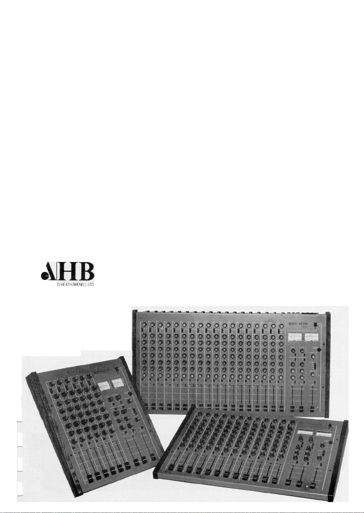
Allen & Heath’s new
stereo 21
SERIES
Allen & Heath proudly unveil their exciting
new range of compact stereo mixers
-
the
21 SERIES. Stylish in looks and superb in
performance, these four models offer outstanding
value for money.
Available in 6, 12, 18 and 24 input versions, the
21 SERIES boasts the useful feature of a separate
mono output derived from the main stereo mix.
Another Plus is the incorporation of an extensive
interface facility to ensure accurate compatibility
with external equipment, and enables two or more
mixers to be linked together for single flexible
operation. A separate power supply unit keeps
nasty hum fields at bay, letting the sound come
through clean and clear.
The 21 SERIES Stereo Mixers by Allen & Heath
are available now.
e
1
ALLEN AN
69 Ship Street
Brighton BNl 1AE
England
Tel,
(0273) 24928
Five Connair Road
Orange) CT 0477
USA
Tel. (203) 795 3594
Page 2
AUDIO QUALITY
Advanced low-noise circuitry boasts a high
slew rate of 13
V/uS,
permitting faithful
reproduction of transient information. Each
mixer is supplied complete with its own
external power supply to ensure that hum
fields are kept to a
minimum. Phantom power
is available as an optional extra. As the
comprehensive PFL system overrides all
monitor outputs and metering, easy checks
may be made on all incoming and outgoing
signals.
MONO OUTPUT
Invaluable as an extra on-stage foldback mix
or as a feed to a mono PA system, permitting
the main stereo faders to be used as
sub-groups or outputs to a stereo recorder.
This feature will be of particular interest to the
AV or broadcast user who may need a
dedicated mono output for simultaneous video
recording, or mono transmission.
PRO AND SEMI-PRO CAPABILITY
21 SERIES mixers are supplied with outputs set
for OVU=
+4dBm,
but external links are
provided so that outputs and tape monitor
inputs can be adjusted by the user (or the
dealer) to ensure compatibility with
equipment designed for lower operating
levels. A thoughtful facility that will make life a
lot easier for the small budget studio. All-steel
construction provides strength and good
electrical screening.
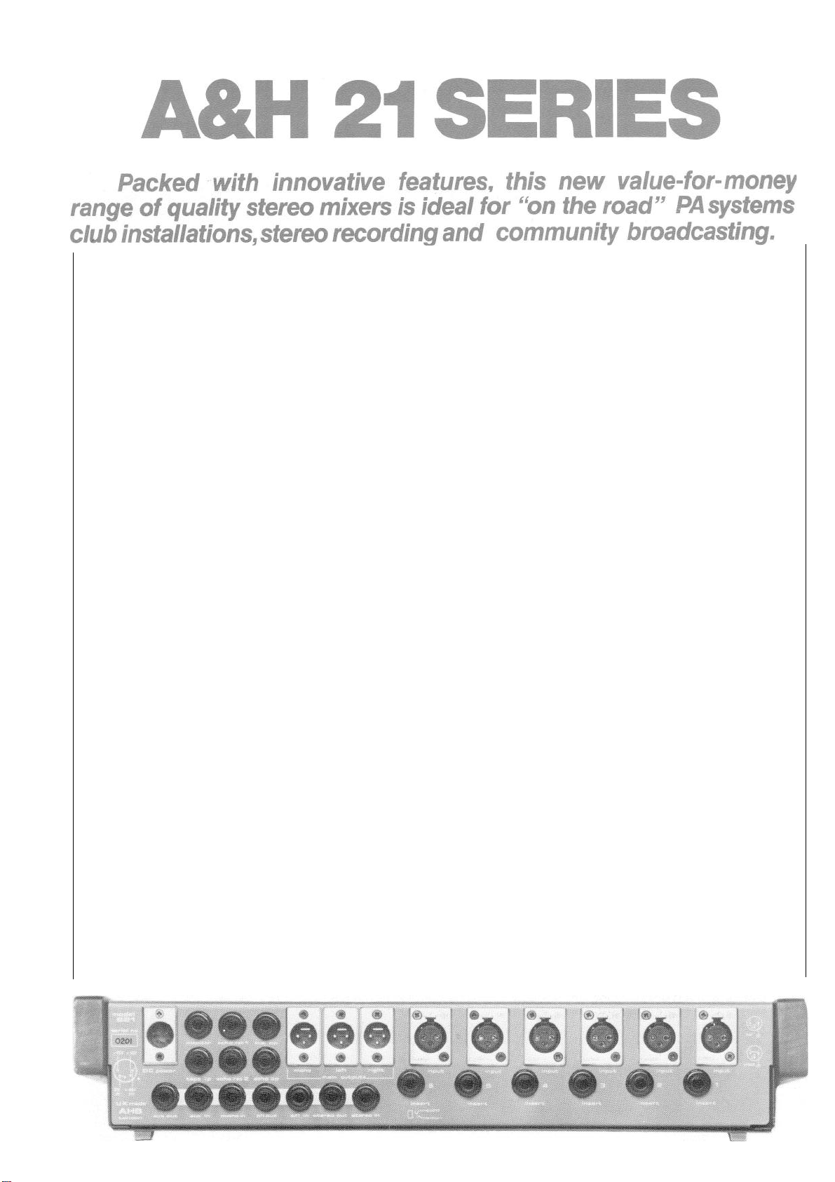
PLUGABILITY
Rear panel sockets provide bus access points
for stereo and mono outputs, cue and echo
sends, and the PFL system. Thus, two or more
21 SERIES mixers may be conveniently linked
for single operation, greatly increasing the
input potential and all-round flexibility of this
new range.
INPUT CHANNEL
*
Electronically-balanced transformerless
FEATURES
microphone input on XLR socket, switchable
to a high impedance balanced line input when
required.
*
Effects insertion point that can also be used
as a line level input or as a spare effects send.
*
20dB pad switch.
*
3
Band equaliser with mid-frequency sweep
from
400Hz
to
6kHz.
*
Pre-fade cue send and post-fade echo send.
*
Channel pan pot and PFL Selector.
*LED peak overload indicator and smooth
travel, long throw fader, providing a high
degree of operator control.
OUTPUT SECTION FEATURES
*
Twin illuminated VU meters with associated
PFL override LED indicator.
*
Two echo returns, each with PFL, cue send,
level and Pan.
*
Cue and echo send masters, both with PFL.
*
Main Left and Right outputs and mono output
on XLR sockets (all featuring PFL selectors).
MONITOR FACILITIES
The two independently-controlled stereo
outputs to headphone and monitor amplifier
can be switched to Mono. An off-tape return
from a stereo recorder may also be selected,
enabling A/B monitoring during recording.
TECHNICAL SPECIFICATION
MIC INPUT
Equivalent Input Noise - 125.5
LINE INPUT
(Further
EQUALISATION
HARMONIC DISTORTION typically
OUTPUT
Recommended load greater than
Maximum output +21dBv
DIMENSIONS Model 621
674x475x100
+20dB
to
+60dB
(PAD
-20dB) 1.5kohm
dBm
-5dB to +36dB (PAD -12dB)
10dB
gain available at fader)
HF
10kHz
(shelving)
MF 400Hz- 6kHz
LF
100Hz
(shelving)
Unbalanced 30 ohm source impedance
458x475x100
Model 1821
891x475x100
10kohm
+/- 15dB
(Q = 1.4)
+/- 15dB
<0.05%
2kohm
Model
+/-
13dB
1221
Page 3

STEREO 21 SERIES
OWNER'S HANDBOOK
Page 4

SPECIFICATION:
Construction:
steel main panel and covers, hard stove enamel paint
finish with epoxy ink screenprinted legend.
modular electronic printed circuit assemblies. IC
op-amp and discrete transistor audio system of
transformerless design.
Size& Weight: MIXER
Width
Depth
Height
621 457 476 90mm
(600)
1221 673
(710)
1821 889
(930)
(620)
476 90
(620)
476
(620)
2421 1105 476
(1160)
(620)
90
90
(160)
(160)
(160)
(160)
bracketed figures = in shipping carton.
Connectors: Channel input, stereo and mono outputs;
locking.
POWER SUPPLY: External,
All others
type MPS7
Phantom power option
1/4"
jack.
110-120v or
+48v MPS7P.
220-240v
(Symmetrical system)
Semi-
Weight
9.5kg
(14.0)
14.0
(19.0)
18.5
(24.0)
23.5
(29.0)
3
pin XLR-type
AC.
CONNECTIONS:
FUSES:
OUTPUT =
+15v DC, smoothed and regulated
0.5 amps per rail
INPUT =
AC mains voltage at
220/240v
110/120v
setting =
setting =
50/60Hz
212v to
106v to
250v
130v
AC
AC
30VA max
PHANTOM POWER available as an option (specify MPS 7-P)
=
+48v
DC,
MAINS INPUT = flying
DC OUTPUT = flying 4-core lead
smoothed and regulated at
3-core
lead
1.5m
1.5m
in a
5-pin
pin
XLR female in-line plug.
1
=
-15V
DC
50mA
long
long terminated
pin 2 = 0V
pin 3 = 0V
+15V
DC
PHANTOM POWER (if fitted)
220/240V
110/120V
pin 4 =
pin 5 =
setting = 500mA quick blow 5 x 20mm
setting = 1A quick blow 1 1/4".
Page 5

GENERAL
All Outputs:
2
Normal Operating Level =
Maximum Output Level =
Output Impedance =
30ohms
+4dBv
+2ldBv 20Hz
to
20kHz
all outputs are protected against damage from accidental short
circuits.
Maximum Gain From Channel Input to Stereo Output:
= +70dB
Frequency Response:
Channel Input to Stereo Output =
30Hz
to
30kHz +/-1dB
Equaliser Characteristics:
HF =
MID =
LF =
15dB
continuously variable at
+/-13dB
and
continuously variable at any frequency between
6kHz.
Q factor =
+/-15dB
continuously variable at
10kHz
400Hz
1.4
100Hz
Total Harmonic Distortion:
Channel Input to Stereo Output typically 0.05% THD
Noise:
20Hz
to
20kHz
MEASURED AT STEREO OUTPUT.
Figures quoted are
noise referred to system operating level.
Microphone Equivalent Input Noise =
Output with Master Faders Closed =
Output with Master Faders Raised,
-125.5dBv
-94dB
ref 0VU
All Inputs Closed better than
-66dB ref 0VU
DIN RMS
621 . . . -68dBm
1221
. . . -66dBm
1821
. . . -63dBm
Output with One Input Raised, mic source
minimum =
-61dB ref 0VU
= 200ohms,
Crosstalk:
Stereo Separation -better than
better than
better than 66dB at
56dB
75dB
at
at
100Hz
1kHz
1OkHz
RMS
EQ flat, gain
Page 6

Channel Inputs:
3
XLR sockets.
of external phantom power supply of up to
Electronically balanced suitable for safe connection
48VDC.
XLR pin 3 = hot
pin 2 = cold
1
pin
Input Impedance
Gain - mic
line
Pad
-
mic =
= screen
-
mic = 1000 to 1500 ohms
line =
= continuously variable from
= continuously variable from
10kohms
+20dB
-5dB
-20dB
line = -12dB
Insertion Points - unbalanced
1/4"
stereo jack sockets
tip = return
ring = send
outer = earth
normal operating level =
Peak Overload Indicator
-
turns on at 3dB before clipping.
+4dBv
Echo Return Inputs:
mono
1/4"
jack sockets
to
to
+60dB
+35dB
Maximum Gain to Stereo Outputs =
Input Impedance =
greater than 4kohms
+16dB
Stereo Tape Input:
stereo
1/4"
jack socket
tip = left
ring = right
outer = earth
Input Impedance = 40kohms
Gain to Monitors
-
0dB
or
+12dB
selectable by an internal connector
for either +4dBv or -8dBv normal operating level.
Stereo and Mono Outputs:
unbalanced XLR sockets
pin 3 = signal
pin 2 = pin
Normal Operating Level = +4dBv or
-8dBv selectable by an internal
connector.
Cue and Echo Outputs:
unbalanced
Normal Operating Level =
1/4"
jack sockets mono
+4dBv
1
= earth
Maximum Gain from Input =
+10dB
Page 7

Monitor Output:
4
stereo
Normal Operating Level =
Maximum Gain =
Headphones Output:
stereo
capable of driving stereo phones of
Tie Buss Svstem:
Stereo Input -stereo
Stereo Output - stereo
Mono Input - mono
1/4"
jack socket
+10dB
1/4"
jack socket
Gain to Stereo Output =
Normal Operating Level =
Gain to Mono Output =
1/4"
jack socket
tip = left
ring = right
outer = earth
+4dBv
1/4"
jack socket
1/4"
jack socket
4ohms to
0dB
600ohms
tip = left
ring = right
outer = earth
0dB
+4dBv
impedance
Auxilliary Input - stereo
Gain to Output = 0dB
Auxilliary Output
PFL Input - stereo
Gain to PFL Output =
DC connect to 0V = PFL activated
PFL Output
Metering:
illuminated VU meters 0VU = +4dBv+4dBv
-
stereo
Normal Operating Level = 4dBv
DC PFL activated = 0V
-
stereo
Normal Operating Level =
1/4"
jack socket
floating =
1/4"
PFL not activated = -8VDC into 1MEGohm load
1/4"
jack socket
1/4"
jack socket
PFL not activated
jack socket
0dB
tip = cue
ring = echo
outer = earth
+4dBv
tip = audio
ring = DC
outer = 0V
PFL Busy Indicator:
turns on when PFL is activated
Page 8

5
PANEL CONTROLS
Input Channel
Place the mixer in front of you and familiarise yourself with the
various functions of the panel controls.
an input channel the first control is:
GAIN
a)
Starting at the top of
This control
stage of the
with the PFL
to find the correct setting.
MIC-LINE
b)
Selects the sensitivity and input impedance of the XLR input
socket to suit either microphone or line-level signals.
PAD
c)
Reduces the sensitivity of the XLR input socket to enable
very high signal levels to be accommodated.
control has already been turned down fully and there is
still too much signal.
HF
d)
Boosts or cuts the high frequency or treble content of an
incoming signal.
MID FREQ and MID
adjusts the sensitivity of the first amplificati
microphone/line input. Use this in conjunction
function,
as described in the OPERATION section,
Use if the gain
on
The first control selects the mid-range frequency to be cut
or boosted by the MID control.
f)
LF
Boosts or cuts the low frequency or bass content of a signal.
g)
Used to send a proportion of the signal present in the input
channel,
destination.
the channel fader and is thus unaffected by fader settings.
Designed to feed on-stage
or to feed headphone/loudspeaker systems in recording/broadcast
situations.
ternal
still be present when the channel fader is down.
via the cue master (see OUTPUT SECTION), to an external
This auxiliary send derives its signal before
Can also be used as an effects send to feed
devices,
providing it is remembered that the feed will
foldback
monitor systems for PA use
ex-
Page 9

6
h) ECHO
Can be used in a similar way to the above control, except
that it is wired post-fader and the feed to an external
effects device will reduce as the channel fader is lowered.
Use in conjunction with the echo master (see OUTPUT SECTION)
to set correct operating level.
PAN
i)
-
Use to position the signal anywhere between left and right
in the stereo mix.
PFL is an abbreviation for Pre-Fader-Listen.
When selected
it enables an operator to check the level of a signal
The
present in the input before the channel fader.
pre-
fade signal level is governed by settings of the gain control
h;i,;;i
equalisation controls (d, e, and f). See OPERATION
.
k) PEAK
The LED (Light Emitting Diode) peak indicator flashes a
warning when the signal level is too high and approaching
the onset of clipping distortion.
1) FADER
Four fader settings are marked for each input channel,
these are:
'+10',
on the fader;
indicating the extra
'O',
(normal operating position) indicating
unity gain between input channel and output section;
and
'infinity'
or channel off.
10dB
boost available
'-10';
Page 10

OUTPUT SECTION
VU METERS
a)
7
The VU meters can read any one of
PFL: when any PFL button is pressed on the mixer, an LED
i)
just above the right VU meter will illuminate (as a
reminder),
level (in mono).
The output signal level of a stereo tape recorder when
ii)
TAPE is selected in the monitor section.
iii)
CUE MASTER
b)
The master control for all the input channel cue sends.
When the associated PFL button is selected the VU meters
will show the level leaving the mixer at the cue output on
the rear panel.
ECHO MASTER
c)
The main stereo mix output from the mixer when STEREO
is selected in the monitor section.
The output from the MONO fader when MONO is selected
iv)
in the monitor section.
and the meters will follow the selected PFL
4
signal sources:
The master control for all the input channel echo sends.
When the associated PFL button is selected the VU meters
will show the level leaving the mixer at the echo output on
the rear panel.
ECHO RETURNS 1 & 2
d)
These identical sections allow 2 line-level signals (eg the
outputs from 2 effects devices) to be added to the stereo mix.
Each have a level control, performing the same function as an
extra input channel fader, and a pan control, to position the
effects signal in the mix as desired.
A cue send control is also provided in each section, so that
a proportion of the effects signal can be sent to the
musicians' headphone monitoring or foldback system.
PFL select is available in each section to allow monitoring of
the effects signals before committing them to the main mix.
LEFT AND RIGHT MASTER FADERS
e)
Control the output level of the stereo mix.
a PFL switch to allow quality checks,
busses independantly, prior to the final output stages of the
mixer.
on the left and right mix
Each provided with
Page 11

8
f) MONO MASTER FADER
Controls the output level of the mono mix.
This mix is a mono sum of the main stereo output, is derived
after the left/right master faders, and therefore depends
upon their position for output level.
PFL select is available to check the signal supplying the
mono output for level and quality.
g) MONITOR SECTION
This section selects the signals available for headphone
monitoring via the top panel socket and/or for control room
monitoring via the monitor output socket on the rear.
There are separate volume controls for headphones and output
to amplifier.
Selecting PFL in any section of the mixer
will override the monitor outputs.
The three monitor source select buttons (Mono, Stereo, Tape)
can be used in permutations described as follows:
BUTTONS DEPRESSED
Mono only
Stereo only
Tape only
MONITOR OUTPUT
Mono mix
Stereo mix
Return from stereo tape machine,
connected to
"Tape In"
socket on rear
panel.
Mono + Stereo
Mono + Stereo + Tape
Stereo + Tape
The VU meters,
except when any PFL function is selected, will
Stereo mix
Stereo tape return
Stereo tape return.
follow the selected monitor source.
We suggest,
as a normal procedure,
left depressed.
This will allow simple switching between
that the Mono button be
Mono and Stereo by operation of the stereo button alone.
Similarly,
as can be seen from the above priority table,
both Mono and Stereo buttons can be left depressed whilst
operating the Tape button for A-B checks.
Page 12

OPERATION
9
Objective:
Assisted
To preserve the quality of the original sound.
by:
Level controls, gain controls, mixer meters, peak indicators, tape
meters and tape.
Level control
Operator control changing the signal level between
sections of a console system, often a passive
device (fader, pot).
Gain control
Operator control changing the shift in signal
level between the input and output of an
amplifier in one section of a console system.
It is said that a monkey with a typewriter would generate the works
of Shakespeare given enough paper and new machines in
hours.
How long would it take him to mix
"I
am not in
6
million
love'?
Those of you with time to spare may like to consider whether an
automation system would increase or decrease the time taken.
Get
to know your equipment and its capabilities and limitations.
Particularly important in console systems are gain and level
controls used in conjunction with level indicators. There is
no way known to beat the physical constraints of thermionic
noise and maximum output level within audio amplifier systems
but intelligent use of gain and level controls gets acceptable,
even excellent results from modest equipment. Allen and Heath
consoles have more than the minimum number of controls essential
between microphone and tape since this allows presentation of
the original sound quality for a wider variety of sound sources
having different signal amplitutudes.
Signal dynamic range:
The difference in signal level between
the loudest and the quietest sections of a
programme.
System dynamic range:
The difference in signal level between the
loudest and quietest signals that can be
faithfully reproduced or transmitted by an
audio amplifier system.
The worst that can happen:
Start with a piece of programme to be mixed and recorded and
two things may happen to reduce the quality of original sound:
Page 13

10
The audio amplifier system noise is allowed to be greater
1)
than the ambient (background) noise of the original sound.
Details of the quieter sections of programme are lost.
2)
The audio amplifier system maximum signal level for
faithful reproduction is exceeded by the original sound.
Details of the louder sections of the programme are lost
and the audio system adds masking distortions generated by
overload of the amplifiers.
Make
some simple tests:
Set up a mic and get someone to play the piano in the studio,
set the mic in close to the piano.
Select PFL on the appropriate mic input, you are hearing only
the input pre-amp and equaliser sections of the console.
Wind up the mic gain control till you get a PFL meter
indication of about 0 VU on loud notes.
Set the monitor level
control to reproduce the tone level of the piano as it is in
the studio.
Can you hear any noise below the programme?
Can you hear any distortion of the notes?
Now back off the monitor level and advance the mic gain control
till the channel peak indicator flashes only on loud notes.
Can you hear more or less noise below the programme?
Can you hear more or less distortion of the notes?
What is the PFL meter now reading (do not worry it will not
burn out)?
It would be OK to run all signals this hot but for one thing.
Back off the monitor level some more and advance the mic gain
control till the channel peak indicator is on all the time.
Sounds bad doesn't it.
The gritty distortion you hear added
to the programme is the sound solid state amplifiers make
when overloaded and is called clipping distortion.
The one thing referred to above is your friendly piano player
hitting the next phrase a little louder
-
pushing the signal
level in the pre-amp above amplifier overload point to produce
the horrible sound we just got
no amount of hard work later on will cancel it.
once the pre-amp has clipped
Your mixer
system has a meter calibrated to guide you where to set the mic
gain control so that those extra loud phrases come out clean
too
?
The margin of loudness between the
0VU
reading
and the
Page 14

11
clipped signal reading is the overload margin of the system.
Going
the other way:
Reset the piano mic 20 feet back.
Back at the console reset the controls to get 0VU again on
loud phrases and reset the monitor level for a true volume
in the control room.
It probably sounds OK.
Now ask the piano player to give you his favourite quiet
subtle number.
Reset the mic gain for 0VU on the PFL meter.
Notice anything about the noise level behind the programme?
You are probably losing detail in the quietest phrases and also
are bugged by a continual background hiss.
Do not worry
Hard fact number two
we are exploring the worst that can happen.
noise added to the programme by the
-
preamp cannot be removed by hard work later on either.
The optimum mic gain setting for the particular programme and
mic placement produces 0VU on loudsection, now you know why
the console has meters and peak indicators on it and why
there is a PFL switch for every section.
These take the
guesswork out of setting gain controls.
The PFL meter tells you the channel signal level as determined
by the input gain control.
Meter indications of 0VU on loud
sections are the maximum that can be used and still retain
the overload margin to faithfully reproduce the unexpected
changes in loudness from a performer.
peril.
Run cooler and you will be adding noise unnecessarily
Run hotter at your
at the preamp stage.
The channel peak indicator is a permanent, eye catching
warning that the overload margin in the channel amplifiers
has nearly gone,
the longer it stays on and the more often
it comes on the closer you are to adding clipping distortion
at the preamp (or equaliser) stage.
At the end of the day your ears are the best and final judge
of sound quality and you may decide to override what the meter
says.
Experience has proved (you may test it yourself) that
certain acoustic sources are not reliably analysed for signal
level by meters.
If in doubt trust your ears.
Get it right at the input preamp first.
Page 15

12
All that has been said about the balance between added noise
and added clipping distortion applies to the other parts of
a console system
show a zero '0' calibration point from which to work as a
start for level balancing and why PFL switches are provided
on the output faders as well as on input channels.
case you can see the signal level at that point in the system
and correct your gain and level control settings to preserve the
original sound quality.
Tape and tape meters
The audio world rightly gets excited about new developments
in tape manufacture that provide lower distortion at
existing signal levels or lower noise from the tape itself
and occasionally both at the same time.
expens
signal degradations are to be avoided.
Do not assume that a signal faithfully reproduced at your
ive and some
not just the preamp.
systems
need great care
This is why the
Noise reduction is
in use if other
faders
In each
console output,
back off-tape
have
amplifiers.
Start with a must and make it a habit.
Use a
or FM radio tuned to inter-station noise to feed the console
outputs and adjust for 0VU meter readings, check that yourmonitor
section is selected for output monitor (stereo), not tape monitor.
On the tape machine select input monitor and adjust the record
level for 0VU reading.
the tape machine to replay monitor and the console monitor
section to tape monitor status.
Provided your tape machine is reasonably well calibrated the
limitations on performance so do tape and tape deck
1kHz
tone generator if available, music synthesiser
nicely beating the meters to 0VU, will come
so
sweet.
In the same way that audio amplifiers
Record a few minutes of tone.
Replay the tape tone.
Switch
meters will show the tone replay level to
console check that the meters show 0VU and adjust the output
level controls of the tape deck if necessary. The console
be 0VU. On the
Page 16

13
inputs for tape signals are preset to a standard signal level
(0VU =
+
4dBm).
There are however three standard signal levels
that different tape decks may produce:
0VU
=
0VU =
0VU =
+4dBm (1.23V
0dBm
(0.775V RMS)
-10dBV (0.3lV
RMS)
RMS).
Consult the page of this book "Tape deck interface" for
guidance on obtaining the best from the
system.
Your Allen and Heath console is engineered to work
tapedeck -
console
perfectly with all three standard level systems.
The important point is that the signal level between console
and tape deck that corresponds to 0VU is the operating level
of your studio system and when console and tape machine are
in agreement you have a fair chance of making good recordings.
Once again your ears are the final judge of the off-tape
quality and may lead you to overrule record level meters.
Use the console monitor section
"tape"
switch to check the
off-tape quality.
importantly listen for added distortion.
You will usually hear added noise but more
Tape is operated
much nearer its overload point than console system amplifiers.
Your console amplifiers deliver rated performance (below
audibility) at all signal levels right up to the onset of
clipping
modern tape decks are similarly blameless.
18dB
above 0VU.
The audio amplifiers in most
Tape however
typically generates 3% third harmonic distortion only 8
to
10dB
over 0VU recording level and more bad sounding
tapes are made as a result of recording too hot than through
.
clipping console amplifiers.
Not only that but tape overloads
sooner at high and low frequencies than at mid-band frequencies
(the
at
The point of this is
the impossible,
1kHz
100Hz
reference point) so imagine the distortion figures
and
10kHz
where bass and strings come.
-
do not expect the hardware to perform
it is already performing a miracle by
comparison with full blown record house equipment of the
early days of sound recording, get the console-tape deck
interface right and learn the capabilities of the audio
amplifiers and tape you use.
Page 17

TAPE DECK INTERFACE
14
Your 21 series mixer is supplied with output levels and tape return
levels set for 0VU on meters =
to change operating levels to suit tape machines that require a
lower operating standard. The output levels from the stereo and mono
outputs and also the input level to the stereo tape input can all be
independantly adjusted.
Stand the mixer on rear panel,
Remove bottom panel using POZI 2 screwdriver.
above shows the positions of the level-match adjustors.
remove the adjustor link and replace the plastic plug the opposite
way round.
circuit board as you replace it.
Make sure that
the plug is aligned with the pins on the
4dBm
.
ensuring safe and adequate support.
It is a very simple operation
The illustration
Simply
Page 18

 Loading...