

Page 1

USER GUIDE
Publication AP6822
Page 2

Limited One Year Warranty
This product is warranted to be free from defects in materials or
workmanship for period of one year from the date of purchase by the
original owner.
To ensure a high level of performance and reliability for which this
equipment has been designed and manufactured, read this User Guide
before operating. In the event of a failure, notify and return the
defective unit to ALLEN & HEATH Limited or its authorised agent as
soon as possible for repair under warranty subject to the following
conditions
Conditions Of Warranty
The equipment has been installed and operated in accordance with the
instructions in this User Guide.
The equipment has not been subject to misuse either intended or
accidental, neglect, or alteration other than as described in the User
Guide or Service Manual, or approved by ALLEN & HEATH.
Any necessary adjustment, alteration or repair has been carried out by
ALLEN & HEATH or its authorised agent.
This warranty does not cover fader wear and tear.
The defective unit is to be returned carriage prepaid to ALLEN &
HEATH or its authorised agent with proof of purchase.
Units returned should be packed to avoid transit damage.
In certain territories the terms may vary. Check with your ALLEN &
HEATH agent for any additional warranty which may apply.
This product complies with the European Electro magnetic Compatibility
directive 2004/108/EC and the European Low Voltage Directive 2006/95/EC.
This product has been tested to EN55103 Parts 1 & 2 1996 for use in
Environments E1, E2, E3, and E4 to demonstrate compliance with the
protection requirements in the European EMC directive 2004/108/EC.
During some tests the specified performance figures of the product were
affected. This is considered permissible and the product has been passed as
acceptable for its intended use. Allen & Heath has a strict policy of ensuring
all products are tested to the latest safety and EMC standards. Customers
requiring more information about EMC and safety issues can contact Allen &
Heath.
NOTE: Any changes or modifications to the console not approved by Allen
& Heath could void the compliance of the console and therefore the users
authority to operate it.
ZED-14, 18 & 24 User Guide AP6822 Issue 5
Copyright © 2007 Allen & Heath Limited. All rights reserved
Allen & Heath Limited
Kernick Industrial Estate, Penryn, Cornwall, TR10 9LU, UK
http://www.allen-heath.com
Allen & Heath 2 ZED-14, 18 & 24 User Guide
Page 3
PACKED ITEMS
Check that you have received the following:
ST RTN
ALT OUT
2TRK RTN
ST RTN
2TRK RTN
MIC MIC MIC MIC MIC MIC
LINE LINE LINE LINE LINE LINE
1
0
0
10
20
20
30
10
10
GAIN
GAIN
0
0
40
MIC
MIC
50
LINE
LINE
-6-10 63 26
-6-10 63 26
100Hz
HF
HF
12kHz
12kHz
-15
-15
+15
650
650
500 1k
500 1k
200
200
2k
3k
120Hz 4k
120Hz 4k
-15HM+15
-15HM+15
LF
LF
80Hz
80Hz
-15 +15
-15 +15
AUX1
AUX1
PRE
PRE
OO +6
OO +6
AUX2
AUX2
PRE
PRE
OO +6
OO +6
AUX3
AUX3
POST POST POST POST POST POST POST POST POST POST
OO +6
OO +6
AUX4
AUX4
POST
POST
OO +6
OO +6
=
=
PAN
PAN
LR
LR
MUTE
PK !
PK !
PFL
10
5
0
5
10
20
30
OO
1 2 3 4 5 6 7-8 9-10 11-12 13-14 RL
5
INSERT4INSERT3INSERT2INSERT
INSERT
0
0
0
10
10
10
10
20
20
20
30
30
30
30
10
10
10
GAIN
GAIN
GAIN
GAIN
0
0
0
40
50
LINE
100Hz
HF
12kHz
+15
2k
3k
LF
80Hz
AUX1
PRE
AUX2
PRE
AUX3
AUX4
POST
PAN
MUTE
PFL
10
5
0
5
10
20
30
OO
0
40
40
40
MIC
MIC
MIC
MIC
50
50
50
LINE
LINE
LINE
-6-10 63 26
-6-10 63 26
-6-10 63 26
100Hz
100Hz
100Hz
HF
HF
HF
12kHz
12kHz
12kHz
-15
-15
-15
-15
+15
+15
+15
650
650
650
500 1k
500 1k
500 1k
500 1k
200
200
200
200
2k
2k
2k
3k
3k
3k
120Hz 4k
120Hz 4k
120Hz 4k
120Hz 4k
-15HM+15
-15HM+15
-15HM+15
-15HM+15
LF
LF
LF
80Hz
80Hz
80Hz
-15 +15
-15 +15
-15 +15
-15 +15
AUX1
AUX1
AUX1
PRE
PRE
PRE
OO +6
OO +6
OO +6
AUX2
AUX2
AUX2
PRE
PRE
PRE
OO +6
OO +6
OO +6
AUX3
AUX3
AUX3
OO +6
OO +6
OO +6
AUX4
AUX4
AUX4
POST
POST
POST
OO +6
OO +6
OO +6
=
=
=
PAN
PAN
PAN
LR
LR
LR
MUTE
MUTE
MUTE
PK !
PK !
PK !
PK !
PFL
PFL
PFL
10
10
10
5
5
5
0
0
0
5
5
5
10
10
10
20
20
20
30
30
30
OO
OO
OO
REC OUT
L
L
R
R
L/M
L/M
6
ST2 IN
ST3 IN
ST1 IN
INSERT
R
R
0
ST
2TRK
USB
10
-5
-5
-5
20
30
-10
-10
-10
10
RTN
RTN
RTN
0
0
-20
-20
-20
40
5
5
-30
-30
-30
50
OO 10
OO 10
OO 10
-6-10 63 26
ON
ON
100Hz
To LR
To LR
To 7-8
To 9-10
+15
-5
-5
-5
650
ST3
ST2
ST1
-10
-10
-10
0
0
IN
IN
IN
-20
-20
-20
2k
5
5
-30
-30
-30
3k
OO
OO
10
OO
10
HF
HF
HF
12kHz
12kHz
12kHz
-15 +15
-15 +15
-15 +15
LF
LF
LF
80Hz
80Hz
80Hz
-15 +15
-15 +15
-15 +15
STEREO
STEREO
STEREO
AUX1
AUX1
AUX1
PRE
PRE
PRE
OO +6
OO +6
OO +6
OO +6
AUX2
AUX2
AUX2
PRE
PRE
PRE
OO +6
OO +6
OO +6
OO +6
AUX3
AUX3
AUX3
OO +6
OO +6
OO +6
OO +6
AUX4
AUX4
AUX4
POST
POST
POST
OO +6
OO +6
OO +6
OO +6
=
=
=
=
BAL
BAL
BAL
LR
LR
LR
LR
MUTE
MUTE
MUTE
PK !
PK !
PK !
PFL
PFL
PFL
10
10
10
5
5
5
0
0
0
5
5
5
10
10
10
20
20
20
30
30
30
OO
OO
OO
L
R
L/MRL/M
0
5
ON
To LR
To 11-12
0
5
10
MUTE
PFL
10
5
0
5
10
20
30
OO
MIC
MIC
MIC
MIC
MIC
MIC
MIC
MIC
ALT OUT
AUX1 OUT
INSERT L
MAIN OUT
L
L
R
INSERT R
AUX2 OUT
R
AUX3 OUT
MONO OUT
ST4 IN
R
PHONES
AUX4 OUT
USB
SENDRETURN
POWER
AUX1-2
AUX 3-4
48V
+16
+16
LR PRE
+9
+9
PHANTOM POWER
+6
+6
+3
+3
UP=LR post
0
0
ALLEN HEATH
-5
-3
-3
ST4
-10
-6
-6
0
IN
-20
-9
-9
-12
-12
5
-30
-16
-16
-20
-20
OO
10
-30
-30
HF
L
R
12kHz
PFL ACTIVE
-15 +15
LF
80Hz
-15 +15
AUX1
PRE
OO +6
AUX2
PRE
OO +6
AUX3
OO +6
AUX4
POST
OO +6
BAL
LR
PK !
&
PHONES
MIN MAX
AUX1
STEREO
STEREO
AUX2
2TRK RTN
USB RTN
ALT
OUT
0
OO +6
LR
MONITOR
PRE
LR
POST
=
AUX1
MASTER
0
OO +6
AUX2
MASTER
MUTE
0
OO +6
PFL
10
10
5
5
0
0
5
5
10
10
20
20
30
30
OO
OO
OR
LINE
LINE
LINE
LINE
1
INSERT
0
0
10
20
20
30
10
10
GAIN
GAIN
0
0
40
MIC
MIC
50
LINE
LINE
-6-10 63 26
-6-10 63 26
100Hz
HF
HF
12kHz
12kHz
-15
-15
+15
650
650
1k
500
500
200
200
2k
3k
120Hz 4k
120Hz 4k
-15MF+15
-15MF+15
LF
LF
80Hz
80Hz
-15 +15
-15 +15
AUX1
AUX1
PRE
PRE
+6
AUX2
AUX2
PRE
PRE
+6
AUX3
AUX3
POST
POST
+6
AUX4
AUX4
POST
POST
+6
=
=
PAN
PAN
LR
LR
MUTE
PK !
PK !
PFL
10
5
0
5
10
20
30
OO
1
LINE
2
3
4
5
INSERT
INSERT
INSERT
INSERT
0
0
0
10
30
GAIN
40
50
LINE
100Hz
HF
12kHz
+15
1k
2k
3k
LF
80Hz
AUX1
PRE
+6
AUX2
PRE
+6
AUX3
POST
+6
AUX4
POST
+6
PAN
MUTE
PFL
10
5
0
5
10
20
30
OO
2
0
10
10
10
20
20
20
30
30
30
10
10
10
10
GAIN
GAIN
GAIN
0
0
0
0
40
40
40
MIC
MIC
MIC
MIC
50
50
50
LINE
LINE
LINE
-6-10 63 26
-6-10 63 26
-6-10 63 26
-6-10 63 26
100Hz
100Hz
100Hz
HF
HF
HF
12kHz
12kHz
12kHz
-15
-15
-15
-15
+15
+15
+15
650
650
650
1k
1k
1k
500
500
500
500
200
200
200
200
2k
2k
2k
3k
3k
3k
120Hz 4k
120Hz 4k
120Hz 4k
120Hz 4k
-15MF+15
-15MF+15
-15MF+15
-15MF+15
LF
LF
LF
80Hz
80Hz
80Hz
-15 +15
-15 +15
-15 +15
-15 +15
AUX1
AUX1
AUX1
PRE
PRE
PRE
+6
+6
+6
AUX2
AUX2
AUX2
PRE
PRE
PRE
+6
+6
+6
AUX3
AUX3
AUX3
POST
POST
POST
+6
+6
+6
AUX4
AUX4
AUX4
POST
POST
POST
+6
+6
+6
=
=
=
PAN
PAN
PAN
LR
LR
LR
LR
MUTE
MUTE
MUTE
PK !
PK !
PK !
PK !
PFL
PFL
PFL
10
10
10
5
5
5
0
0
0
5
5
5
10
10
10
20
20
20
30
30
30
OO
OO
OO
3
4
5
MIC
LINE
LINE
LINE
LINE
6
7
8
9
INSERT
INSERT
INSERT
INSERT
0
0
0
10
10
10
20
650
=
10
20
20
20
30
30
30
30
10
10
10
GAIN
GAIN
GAIN
GAIN
0
0
0
40
40
40
40
MIC
MIC
MIC
50
100Hz
+15
1k
2k
3k
+6
+6
+6
+6
MUTE
PFL
10
5
0
5
10
20
30
OO
6
MIC
50
50
50
LINE
LINE
LINE
LINE
-6-10 63 26
-6-10 63 26
-6-10 63 26
100Hz
100Hz
100Hz
HF
HF
HF
HF
12kHz
12kHz
12kHz
12kHz
-15
-15
-15
+15
+15
+15
650
650
650
1k
1k
1k
500
500
500
200
200
200
200
2k
2k
2k
3k
3k
3k
120Hz 4k
120Hz 4k
120Hz 4k
-15MF+15
-15MF+15
-15MF+15
LF
LF
LF
LF
80Hz
80Hz
80Hz
80Hz
-15 +15
-15 +15
-15 +15
AUX1
AUX1
AUX1
AUX1
PRE
PRE
PRE
PRE
+6
+6
+6
AUX2
AUX2
AUX2
AUX2
PRE
PRE
PRE
PRE
+6
+6
+6
AUX3
AUX3
AUX3
AUX3
POST
POST
POST
POST
+6
+6
+6
AUX4
AUX4
AUX4
AUX4
POST
POST
POST
POST
+6
+6
+6
=
=
=
PAN
PAN
PAN
PAN
LR
LR
LR
MUTE
MUTE
MUTE
PK !
PK !
PK !
PFL
PFL
PFL
10
10
10
5
5
5
0
0
0
5
5
5
10
10
10
20
20
20
30
30
30
OO
OO
OO
7
8
9
REC OUT
MIC
L
R
LINE
L/M
10
ST1 IN
INSERT
R
0
ST
10
-5
20
30
10
-10
RTN
0
0
40
-20
5
50
-30
-6-10 63 26
10
ON
100Hz
To LR
To CH
-15
+15
-5
650
ST1
1k
-10
500
0
IN
-20
2k
5
-30
3k
10
120Hz 4k
HF
12kHz
-15 +15
-15MF+15
LF
80Hz
-15 +15
-15 +15
STEREO
AUX1
PRE
+6
+6
AUX2
PRE
+6
+6
AUX3
POST
+6
+6
AUX4
POST
+6
+6
=
=
BAL
LR
LR
MUTE
MUTE
PK !
PK !
PFL
PFL
10
10
5
5
0
0
5
5
10
10
20
20
30
30
OO
OO
O
11-12
10
AUX1 OUT
MAIN OUT
INSERT L
L
L
L
L
R
R
R
INSERT R
AUX2 OUT
L/M
L/M
L/M
R
AUX3 OUT
ST 2 IN
R
2 TRK
-5
-10
RTN
0
-20
5
-30
10
ON
To LR
To CH
-5
ST2
-10
0
IN
-20
5
-30
10
HF
12kHz
-15 +15
LF
80Hz
-15 +15
STEREO
AUX1
PRE
+6
AUX2
PRE
+6
AUX3
POST
+6
AUX4
POST
+6
=
BAL
LR
MUTE
PK !
PFL
10
5
0
5
10
20
30
OO
13-14
MONO OUT
ST 3 IN
ST4 IN
R
R
PHONES
AUX4 OUT
USB
USB
-5
-10
SENDRETURN
RTN
0
-20
POWER
5
-30
AUX1-2
10
ON
AUX 3-4
48V
To LR
+16
ST4
IN
HF
12kHz
LF
80Hz
AUX1
PRE
AUX2
PRE
AUX3
POST
AUX4
POST
BAL
UP=LR post
-10
-20
-30
-15 +15
-15 +15
LR
PK !
LR PRE
-5
0
5
10
STEREO
+6
+6
+6
+6
=
MUTE
PFL
10
5
0
5
10
20
30
OO
17-18 RL
+16
+9
+9
PHANTOM POWER
+6
+6
+3
+3
0
0
ALLEN HEATH
-3
-3
-6
-6
-9
-9
-12
-12
-16
-16
-20
-20
-30
-30
L
R
PFL ACTIVE
&
PHONES
MIN MAX
AUX1
STEREO
AUX2
2TRK RTN
USB RTN
ALT
OUT
0
+6
LR
MONITOR
PRE
LR
POST
AUX1
MASTER
0
+6
AUX2
MASTER
0
+6
10
5
0
5
10
20
30
OO
To CH
-5
ST3
-10
0
IN
-20
5
-30
10
HF
12kHz
-15 +15
LF
80Hz
-15 +15
STEREO
AUX1
PRE
+6
AUX2
PRE
+6
AUX3
POST
+6
AUX4
POST
+6
=
BAL
LR
MUTE
PK !
PFL
10
5
0
5
10
20
30
OO
15-16
OR
ST RTN
MICMICMICMICMICMIC
MIC
MIC
MIC
MIC
MIC
MIC
MIC
MIC
MIC
MIC
LINE LINE LINE LINE LINE LINE
LINE
LINE
LINE
LINE
LINE
LINE
LINE
LINE
LINE
LINE
3
2
1
INSERT
INSERT
INSERT
0
0
0
0
0
0
0
0
0
0
0
10
10
10
10
10
10
10
10
20
20
20
20
20
20
20
20
30
30
30
30
30
30
30
30
10
10
10
10
10
10
10
10
10
10
10
GAIN
GAIN
GAIN
GAIN
GAIN
GAIN
GAIN
GAIN
GAIN
GAIN
GAIN
0
0
0
0
0
0
0
0
0
0
0
40
40
40
40
40
40
40
40
MIC
MIC
MIC
MIC
MIC
MIC
MIC
MIC
MIC
MIC
MIC
50
50
50
50
50
50
50
50
LINE
LINE
LINE
LINE
LINE
LINE
LINE
LINE
LINE
LINE
LINE
-6-1 0 63 26
-6-1 0 63 26
-6-1 0 63 26
-6-1 0 63 26
-6-1 0 63 26
-6-1 0 63 26
-6-1 0 63 26
-6-1 0 63 26
-6-1 0 63 26
-6-1 0 63 26
-6-1 0 63 26
100Hz
100Hz
100Hz
100Hz
100Hz
100Hz
100Hz
100Hz
HF
HF
HF
HF
HF
HF
HF
HF
HF
HF
HF
12kHz
12kHz
12kHz
12kHz
12kHz
12kHz
12kHz
12kHz
12kHz
12kHz
12kHz
+15
+15
+15
+15
+15
+15
+15
+15
-15
-15
-15
-15
-15
-15
-15
-15
-15
-15
-15
650
650
650
650
650
650
650
650
500 1k
500 1k
500 1k
500 1k
500 1k
500 1k
500 1k
500 1k
500 1k
500 1k
500 1k
200
200
200
200
200
200
200
200
200
200
200
2k
2k
2k
2k
2k
2k
2k
2k
3k
3k
3k
3k
3k
3k
3k
3k
120Hz 4k
120Hz 4k
120Hz 4k
120Hz 4k
120Hz 4k
120Hz 4k
120Hz 4k
120Hz 4k
120Hz 4k
120Hz 4k
120Hz 4k
-15HM+15
-15HM+15
-15HM+15
-15HM+15
-15HM+15
-15HM+15
-15HM+15
-15HM+15
-15HM+15
-15HM+15
-15HM+15
LF
LF
LF
LF
LF
LF
LF
LF
LF
LF
LF
80Hz
80Hz
80Hz
80Hz
80Hz
80Hz
80Hz
80Hz
80Hz
80Hz
80Hz
-15 +15
-15 +15
-15 +15
-15 +15
-15 +15
-15 +15
-15 +15
-15 +15
-15 +15
-15 +15
-15 +15
AUX1
AUX1
AUX1
AUX1
AUX1
AUX1
AUX1
AUX1
AUX1
AUX1
AUX1
PRE
PRE
PRE
PRE
PRE
PRE
PRE
PRE
PRE
PRE
PRE
OO +6
OO +6
OO +6
OO +6
OO +6
OO +6
OO +6
OO +6
OO +6
OO +6
OO +6
AUX2
AUX2
AUX2
AUX2
AUX2
AUX2
AUX2
AUX2
AUX2
AUX2
AUX2
PRE
PRE
PRE
PRE
PRE
PRE
PRE
PRE
PRE
PRE
PRE
OO +6
OO +6
OO +6
OO +6
OO +6
OO +6
OO +6
OO +6
OO +6
OO +6
OO +6
AUX3
AUX3
AUX3
AUX3
AUX3
AUX3
AUX3
AUX3
AUX3
AUX3
AUX3
POST
POST
POST
POST
POST
POST
POST
POST
POST
POST
POST
OO +6
OO +6
OO +6
OO +6
OO +6
OO +6
OO +6
OO +6
OO +6
OO +6
OO +6
AUX4
AUX4
AUX4
AUX4
AUX4
AUX4
AUX4
AUX4
AUX4
AUX4
AUX4
POST
POST
POST
POST
POST
POST
POST
POST
POST
POST
POST
OO +6
OO +6
OO +6
OO +6
OO +6
OO +6
OO +6
OO +6
OO +6
OO +6
OO +6
=
=
=
=
=
=
=
=
PAN
PAN
PAN
PAN
PAN
PAN
PAN
PAN
PAN
PAN
PAN
LR
LR
LR
LR
LR
LR
LR
LR
LR
LR
LR
MUTE
MUTE
MUTE
MUTE
MUTE
PK !
PK !
PK !
PK !
PK !
PK !
PK !
PK !
PK !
PK !
PK !
PFL
PFL
PFL
PFL
PFL
10
10
10
10
10
10
10
10
5
5
5
5
5
5
5
5
0
0
0
0
0
0
0
0
5
5
5
5
5
5
5
5
10
10
10
10
10
10
10
10
20
20
20
20
20
20
20
20
30
30
30
30
30
30
30
30
OO
OO
OO
OO
OO
OO
OO
OO
3
2
1
7
6
5
4
INSERT
INSERT
INSERT
INSERT
10
10
10
20
20
20
30
30
30
GAIN
GAIN
GAIN
GAIN
40
40
40
50
50
50
LINE
LINE
LINE
LINE
100Hz
100Hz
100Hz
HF
HF
HF
HF
12kHz
12kHz
12kHz
12kHz
+15
+15
+15
650
650
650
2k
2k
2k
3k
3k
3k
LF
LF
LF
LF
80Hz
80Hz
80Hz
80Hz
AUX1
AUX1
AUX1
AUX1
PRE
PRE
PRE
PRE
AUX2
AUX2
AUX2
AUX2
PRE
PRE
PRE
PRE
AUX3
AUX3
AUX3
AUX3
POST
POST
POST
POST
AUX4
AUX4
AUX4
AUX4
POST
POST
POST
POST
=
=
=
PAN
PAN
PAN
PAN
MUTE
MUTE
PFL
PFL
10
10
10
5
5
5
0
0
0
5
5
5
10
10
10
20
20
20
30
30
30
OO
OO
OO
4
0
0
0
0
0
0
0
0
0
0
0
0
0
10
10
10
10
10
10
10
10
10
10
20
20
20
20
20
20
20
20
20
20
30
30
30
30
30
30
30
30
30
30
10
10
10
10
10
10
10
10
10
10
10
10
10
GAIN
GAIN
GAIN
GAIN
GAIN
GAIN
GAIN
GAIN
GAIN
0
0
0
0
0
0
0
0
0
0
0
0
0
40
40
40
40
40
40
40
40
40
40
MIC
MIC
MIC
MIC
MIC
MIC
MIC
MIC
MIC
MIC
MIC
MIC
MIC
50
50
50
50
50
50
50
50
50
50
LINE
LINE
LINE
LINE
LINE
LINE
LINE
LINE
LINE
-6-10 6326
-6-10 6326
-6-10 63 26
-6-1 0 63 26
-6-1 0 63 26
-6-1 0 63 26
-6-1 0 63 26
-6-10 63 26
-6-10 63 26
-6-10 6326
-6-10 6326
-6-10 6326
-6-10 6326
100Hz
100Hz
100Hz
100Hz
100Hz
100Hz
100Hz
100Hz
100Hz
100Hz
HF
HF
HF
HF
HF
HF
HF
HF
HF
12kHz
12kHz
12kHz
12kHz
12kHz
12kHz
12kHz
12kHz
12kHz
+15
+15
+15
+15
+15
+15
+15
+15
+15
+15
-15
-15
-15
-15
-15
-15
-15
-15
-15
-15
-15
-15
-15
650
650
650
650
650
650
650
650
650
650
500 1k
500 1k
500 1k
500 1k
500 1k
500 1k
500 1k
500 1k
500 1k
500 1k
500 1k
500 1k
500 1k
200
200
200
200
200
200
200
200
200
200
200
200
200
2k
2k
2k
2k
2k
2k
2k
2k
2k
2k
3k
3k
3k
3k
3k
3k
3k
3k
3k
3k
120Hz 4k
120Hz 4k
120Hz 4k
120Hz 4k
120Hz 4k
120Hz 4k
120Hz 4k
120Hz 4k
120Hz 4k
120Hz 4k
120Hz 4k
120Hz 4k
120Hz 4k
-15HM+15
-15HM+15
-15HM+15
-15HM+15
-15HM+15
-15HM+15
-15HM+15
-15HM+15
-15HM+15
-15HM+15
-15HM+15
-15HM+15
-15HM+15
LF
LF
LF
LF
LF
LF
LF
LF
LF
80Hz
80Hz
80Hz
80Hz
80Hz
80Hz
80Hz
80Hz
80Hz
-15 +15
-15 +15
-15 +15
-15 +15
-15 +15
-15 +15
-15 +15
-15 +15
-15 +15
-15 +15
-15 +15
-15 +15
-15 +15
AUX1
AUX1
AUX1
AUX1
AUX1
AUX1
AUX1
AUX1
AUX1
PRE
PRE
PRE
PRE
PRE
PRE
PRE
PRE
PRE
OO +6
OO +6
OO +6
OO +6
OO +6
OO +6
OO +6
OO +6
OO +6
OO +6
OO +6
OO +6
OO +6
AUX2
AUX2
AUX2
AUX2
AUX2
AUX2
AUX2
AUX2
AUX2
PRE
PRE
PRE
PRE
PRE
PRE
PRE
PRE
PRE
OO +6
OO +6
OO +6
OO +6
OO +6
OO +6
OO +6
OO +6
OO +6
OO +6
OO +6
OO +6
OO +6
AUX3
AUX3
AUX3
AUX3
AUX3
AUX3
AUX3
AUX3
AUX3
POST
POST
POST
POST
POST
POST
POST
POST
POST
OO +6
OO +6
OO +6
OO +6
OO +6
OO +6
OO +6
OO +6
OO +6
OO +6
OO +6
OO +6
OO +6
AUX4
AUX4
AUX4
AUX4
AUX4
AUX4
AUX4
AUX4
AUX4
POST
POST
POST
POST
POST
POST
POST
POST
POST
OO +6
OO +6
OO +6
OO +6
OO +6
OO +6
OO +6
OO +6
OO +6
OO +6
OO +6
OO +6
OO +6
=
=
=
=
=
=
=
=
=
=
PAN
PAN
PAN
PAN
PAN
PAN
PAN
PAN
PAN
LR
LR
LR
LR
LR
LR
LR
LR
LR
LR
LR
LR
LR
MUTE
MUTE
MUTE
MUTE
MUTE
MUTE
MUTE
PK !
PK !
PK !
PK !
PK !
PK !
PK !
PK !
PK !
PK !
PK !
PK !
PK !
PFL
PFL
PFL
PFL
PFL
PFL
10
10
10
10
10
10
10
10
10
10
5
5
5
5
5
5
5
5
5
5
0
0
0
0
0
0
0
0
0
0
5
5
5
5
5
5
5
5
5
5
10
10
10
10
10
10
10
10
10
10
20
20
20
20
20
20
20
20
20
20
30
30
30
30
30
30
30
30
30
30
OO
OO
OO
OO
OO
OO
OO
OO
OO
OO
7
6
5
11
10
9
8
INSERT
INSERT
INSERT
0
0
0
0
0
0
0
0
0
0
0
0
0
0
0
0
0
0
10
10
10
10
10
10
10
10
10
10
10
10
10
10
10
10
10
10
20
20
20
20
20
20
20
20
20
20
20
20
20
20
20
20
20
20
20
20
20
30
30
30
30
30
30
30
30
30
30
30
30
30
30
30
30
30
30
10
10
10
10
10
10
10
10
10
10
10
10
10
10
10
10
10
GAIN
GAIN
GAIN
GAIN
GAIN
GAIN
GAIN
GAIN
GAIN
0
0
0
0
0
0
40
40
40
40
40
40
40
40
40
MIC
MIC
MIC
MIC
MIC
MIC
50
50
50
50
50
50
50
50
50
LINE
LINE
LINE
LINE
LINE
LINE
LINE
LINE
LINE
-6-1 0 63 26
-6-10 6326
-6-10 6326
-6-10 6326
-6-1 0 63 26
-6-1 0 63 26
100Hz
100Hz
100Hz
100Hz
100Hz
100Hz
100Hz
100Hz
100Hz
HF
HF
HF
HF
HF
HF
HF
HF
HF
12kHz
12kHz
12kHz
12kHz
12kHz
12kHz
12kHz
12kHz
12kHz
+15
+15
+15
+15
+15
+15
+15
+15
+15
-15
-15
-15
-15
-15
-15
650
650
650
650
650
650
650
650
650
500 1k
500 1k
500 1k
500 1k
500 1k
500 1k
200
200
200
200
200
200
2k
2k
2k
2k
2k
2k
2k
2k
2k
3k
3k
3k
3k
3k
3k
3k
3k
3k
120Hz 4k
120Hz 4k
120Hz 4k
120Hz 4k
120Hz 4k
120Hz 4k
-15HM+15
-15HM+15
-15HM+15
-15HM+15
-15HM+15
-15HM+15
LF
LF
LF
LF
LF
LF
LF
LF
LF
80Hz
80Hz
80Hz
80Hz
80Hz
80Hz
80Hz
80Hz
80Hz
-15 +15
-15 +15
-15 +15
-15 +15
-15 +15
-15 +15
AUX1
AUX1
AUX1
AUX1
AUX1
AUX1
AUX1
AUX1
AUX1
PRE
PRE
PRE
PRE
PRE
PRE
PRE
PRE
PRE
OO +6
OO +6
OO +6
OO +6
OO +6
OO +6
AUX2
AUX2
AUX2
AUX2
AUX2
AUX2
AUX2
AUX2
AUX2
PRE
PRE
PRE
PRE
PRE
PRE
PRE
PRE
PRE
OO +6
OO +6
OO +6
OO +6
OO +6
OO +6
AUX3
AUX3
AUX3
AUX3
AUX3
AUX3
AUX3
AUX3
AUX3
POST POST POST POST POST POST POST POST POST POST
POST
POST
POST
POST
POST
POST
POST
POST
OO +6
OO +6
OO +6
OO +6
OO +6
OO +6
AUX4
AUX4
AUX4
AUX4
AUX4
AUX4
AUX4
AUX4
AUX4
POST
POST
POST
POST
POST
POST
POST
POST
POST
OO +6
OO +6
OO +6
OO +6
OO +6
OO +6
=
=
=
=
=
=
=
=
=
PAN
PAN
PAN
PAN
PAN
PAN
PAN
PAN
PAN
LR
LR
LR
LR
LR
LR
MUTE
MUTE
MUTE
MUTE
MUTE
MUTE
PK !
PK !
PK !
PK !
PK !
PK !
PFL
PFL
PFL
PFL
PFL
PFL
10
10
10
10
10
10
10
10
10
5
5
5
5
5
5
5
5
5
0
0
0
0
0
0
0
0
0
5
5
5
5
5
5
5
5
5
10
10
10
10
10
10
10
10
10
20
20
20
20
20
20
20
20
20
30
30
30
30
30
30
30
30
30
OO
OO
OO
OO
OO
OO
OO
OO
OO
10
9
8
10
GAIN
GAIN
GAIN
GAIN
GAIN
GAIN
GAIN
GAIN
GAIN
0
0
0
0
0
0
0
0
0
0
0
0
40
40
40
40
40
40
40
40
40
MIC
MIC
MIC
MIC
MIC
MIC
MIC
MIC
MIC
MIC
MIC
MIC
50
50
50
50
50
50
50
50
50
LINE
LINE
LINE
LINE
LINE
LINE
LINE
LINE
LINE
-6-1 0 63 26
-6-1 0 63 26
-6-1 0 63 26
-6-1 0 63 26
-6-1 0 63 26
-6-1 0 63 26
-6-1 0 63 26
-6-1 0 63 26
-6-1 0 63 26
-6-1 0 63 26
-6-1 0 63 26
-6-10 63 26
100Hz
100Hz
100Hz
100Hz
100Hz
100Hz
100Hz
100Hz
100Hz
HF
HF
HF
HF
HF
HF
HF
HF
HF
12kHz
12kHz
12kHz
12kHz
12kHz
12kHz
12kHz
12kHz
12kHz
+15
+15
+15
+15
+15
+15
+15
+15
+15
-15
-15
-15
-15
-15
-15
-15
-15
-15
-15
-15
-15
650
650
650
650
650
650
650
650
650
650
650
650
500 1k
500 1k
500 1k
500 1k
500 1k
500 1k
500 1k
500 1k
500 1k
500 1k
500 1k
500 1k
200
200
200
200
200
200
200
200
200
200
200
200
2k
2k
2k
2k
2k
2k
2k
2k
2k
3k
3k
3k
3k
3k
3k
3k
3k
3k
120Hz 4k
120Hz 4k
120Hz 4k
120Hz 4k
120Hz 4k
120Hz 4k
120Hz 4k
120Hz 4k
120Hz 4k
120Hz 4k
120Hz 4k
120Hz 4k
-15HM+15
-15HM+15
-15HM+15
-15HM+15
-15HM+15
-15HM+15
-15HM+15
-15HM+15
-15HM+15
-15HM+15
-15HM+15
-15HM+15
LF
LF
LF
LF
LF
LF
LF
LF
LF
80Hz
80Hz
80Hz
80Hz
80Hz
80Hz
80Hz
80Hz
80Hz
-15 +15
-15 +15
-15 +15
-15 +15
-15 +15
-15 +15
-15 +15
-15 +15
-15 +15
-15 +15
-15 +15
-15 +15
AUX1
AUX1
AUX1
AUX1
AUX1
AUX1
AUX1
AUX1
AUX1
PRE
PRE
PRE
PRE
PRE
PRE
PRE
PRE
PRE
OO +6
OO +6
OO +6
OO +6
OO +6
OO +6
OO +6
OO +6
OO +6
OO +6
OO +6
OO +6
AUX2
AUX2
AUX2
AUX2
AUX2
AUX2
AUX2
AUX2
AUX2
PRE
PRE
PRE
PRE
PRE
PRE
PRE
PRE
PRE
OO +6
OO +6
OO +6
OO +6
OO +6
OO +6
OO +6
OO +6
OO +6
OO +6
OO +6
OO +6
AUX3
AUX3
AUX3
AUX3
AUX3
AUX3
AUX3
AUX3
AUX3
POST
POST
POST
POST
POST
POST
OO +6
OO +6
OO +6
OO +6
OO +6
OO +6
OO +6
OO +6
OO +6
OO +6
OO +6
OO +6
AUX4
AUX4
AUX4
AUX4
AUX4
AUX4
AUX4
AUX4
AUX4
POST
POST
POST
POST
POST
POST
POST
POST
POST
OO +6
OO +6
OO +6
OO +6
OO +6
OO +6
OO +6
OO +6
OO +6
OO +6
OO +6
OO +6
=
=
=
=
=
=
=
=
=
=
=
=
PAN
PAN
PAN
PAN
PAN
PAN
PAN
PAN
PAN
LR
LR
LR
LR
LR
LR
LR
LR
LR
LR
LR
LR
MUTE
MUTE
MUTE
MUTE
MUTE
MUTE
PK !
PK !
PK !
PK !
PK !
PK !
PK !
PK !
PK !
PK !
PK !
PK !
PFL
PFL
PFLPFLPFLPFLPFLPFLPFLPFLPFLPFLPFL
PFL
PFL
PFL
PFL
PFL
PFL
10
10
10
10
10
10
10
10
10
5
5
5
5
5
5
5
5
5
0
0
0
0
0
0
0
0
0
5
5
5
5
5
5
5
5
5
10
10
10
10
10
10
10
10
10
20
20
20
20
20
20
20
20
20
30
30
30
30
30
30
30
30
30
OO
OO
OO
OO
OO
OO
OO
OO
OO
11 12 13 14 15 16 17-18 19-20 21-22 23-24 RL
INSERT14INSERT13INSERT12INSERT
10
10
10
30
30
30
GAIN
GAIN
GAIN
40
40
40
MIC
MIC
MIC
50
50
50
LINE
LINE
LINE
100Hz
100Hz
100Hz
HF
HF
HF
12kHz
12kHz
12kHz
+15
+15
+15
200
200
200
2k
2k
2k
3k
3k
3k
LF
LF
LF
80Hz
80Hz
80Hz
AUX1
AUX1
AUX1
PRE
PRE
PRE
AUX2
AUX2
AUX2
PRE
PRE
PRE
AUX3
AUX3
AUX3
POST
POST
AUX4
AUX4
AUX4
POST
POST
POST
PAN
PAN
PAN
MUTE
MUTE
PFL
PFL
PFL
10
10
10
5
5
5
0
0
0
5
5
5
10
10
10
20
20
20
30
30
30
OO
OO
OO
2TRK RTN
L
R
L/M
16
15
ST2 IN
ST1 IN
INSERT
INSERT
R
0
0
0
0
0
0
ST
2TRK
10
10
10
10
10
10
-5
-5
20
20
20
20
20
20
30
30
30
30
30
30
10
10
10
10
-10
-10
10
10
RTN
RTN
0
GAIN
GAIN
GAIN
0
0
0
0
0
0
-20
-20
40
40
40
40
40
40
MIC
MIC
MIC
5
-30
-30
50
50
50
50
50
50
LINE
LINE
LINE
OO 10
OO 10
-6-10 6326
-6-10 6326
-6-10 6326
-6-10 6326
-6-10 6326
-6-10 6326
ON
ON
100Hz
100Hz
100Hz
100Hz
100Hz
100Hz
HF
HF
HF
To LR
To LR
12kHz
12kHz
12kHz
To CH
To CH
+15
+15
+15
+15
+15
+15
-15
-15
-15
-15
-15
-15
-5
-5
650
650
650
650
650
650
ST2
ST1
-10
-10
500 1k
500 1k
500 1k
500 1k
500 1k
500 1k
0
IN
IN
200
200
200
-20
-20
2k
2k
2k
2k
2k
2k
5
-30
-30
3k
3k
3k
3k
3k
3k
OO
10
OO
10
120Hz 4k
120Hz 4k
120Hz 4k
120Hz 4k
120Hz 4k
120Hz 4k
HF
HF
12kHz
12kHz
-15 +15
-15 +15
-15HM+15
-15HM+15
-15HM+15
-15HM+15
-15HM+15
-15HM+15
LF
LF
LF
LF
LF
80Hz
80Hz
80Hz
80Hz
80Hz
-15 +15
-15 +15
-15 +15
-15 +15
-15 +15
-15 +15
-15 +15
-15 +15
STEREO
STEREO
AUX1
AUX1
AUX1
AUX1
AUX1
PRE
PRE
PRE
PRE
PRE
OO +6
OO +6
OO +6
OO +6
OO +6
OO +6
OO +6
OO +6
AUX2
AUX2
AUX2
AUX2
AUX2
PRE
PRE
PRE
PRE
PRE
OO +6
OO +6
OO +6
OO +6
OO +6
OO +6
OO +6
OO +6
AUX3
AUX3
AUX3
AUX3
AUX3
POST
POST
OO +6
OO +6
OO +6
OO +6
OO +6
OO +6
OO +6
OO +6
AUX4
AUX4
AUX4
AUX4
AUX4
POST
POST
POST
POST
POST
OO +6
OO +6
OO +6
OO +6
OO +6
OO +6
OO +6
OO +6
=
=
=
=
=
=
=
=
BAL
BAL
PAN
PAN
PAN
LR
LR
LR
LR
LR
LR
LR
LR
MUTE
MUTE
MUTE
MUTE
MUTE
MUTE
PK !
PK !
PK !
PK !
PK !
PK !
PK !
PK !
PFL
PFL
PFL
PFL
PFL
PFL
PFL
PFL
10
10
10
10
10
10
10
5
5
5
5
5
5
5
0
0
0
0
0
0
0
5
5
5
5
5
5
5
10
10
10
10
10
10
10
20
20
20
20
20
20
20
30
30
30
30
30
30
30
OO
OO
OO
OO
OO
OO
OO
ZED-14, ZED-18 or ZED-24 MIXER
REC OUT
ALT OUT
INSERT L
AUX1 OUT
L
R
L/MRL/M
0
5
ST4
0
IN
5
HF
12kHz
LF
80Hz
AUX1
PRE
AUX2
PRE
AUX3
AUX4
POST
BAL
5
0
5
MAIN OUT
L
L
R
INSERT R
AUX2 OUT
R
AUX3 OUT
MONO OUT
ST4 IN
R
PHONES
AUX4 OUT
USB
SENDRETURN
POWER
AUX1-2
AUX 3-4
48V
+16
+16
+9
+9
LR PRE
PHANTOM POWER
+6
+6
+3
+3
UP=LR post
0
0
ALLEN HEATH
-5
-3
-3
-10
-6
-6
0
-20
-9
-9
-12
-12
5
-30
-16
-16
-20
-20
OO
10
-30
-30
L
R
PFL ACTIVE
-15 +15
-15 +15
OO +6
OO +6
OO +6
OO +6
LR
PK !
&
PHONES
MIN MAX
AUX1
STEREO
STEREO
AUX2
2TRK RTN
USB RTN
ALT
OUT
0
OO +6
LR
MONITOR
PRE
LR
POST
=
AUX1
MASTER
0
OO +6
AUX2
MASTER
MUTE
0
OO +6
PFL
10
10
5
5
0
0
5
5
10
10
20
20
30
30
OO
OO
L
R
L/M
ST3 IN
R
USB
-5
-10
RTN
0
-20
5
-30
OO 10
ON
To LR
To CH
-5
ST3
-10
0
IN
-20
5
-30
OO
10
HF
12kHz
-15 +15
LF
80Hz
-15 +15
STEREO
AUX1
PRE
OO +6
AUX2
PRE
OO +6
AUX3
OO +6
AUX4
POST
OO +6
=
BAL
LR
MUTE
PK !
PFL
10
10
5
0
5
10
10
20
20
30
30
OO
OO
Mains Lead
Check that the correct
mains plug is fitted.
SONAR LE
SONAR X1 LE
Type A-B USB Lead
To connect the ZED to
your computer.
Music Software Install disk.
INSTALL
cakewalk
Allen & Heath 3 ZED-14, 18 & 24 User Guide
Page 4

SAFETY INSTRUCTIONS
WARNINGS - Read the following before proceeding :
CAUTION
ATTENTION: RISQUE DE CHOC ELECTRIQUE – NE PAS OUVRIR
Read instructions: Retain these safety and operating instructions for future reference. Adhere to all warnings printed here
Do not remove cover: Operate the console with its covers correctly fitted.
Power sources: Connect the console to a mains power unit only of the type described in this User Guide and marked
Power cord routing: Route the power cord so that it is not likely to be walked on, stretched or pinched by items placed
and on the console. Follow the operating instructions printed in this User Guide.
on the rear panel. Use the power cord with sealed mains plug appropriate for your local mains supply as provided with the console. If the provided plug does not fit into your outlet consult your service
agent for assistance.
upon or against it.
Grounding: Do not defeat the grounding and polarisation means of the power cord plug. Do not remove or tam-
per with the ground connection in the power cord.
!
WARNING: This equipment must be earthed.
Water and moisture:
To reduce the risk of fire or electric shock do not expose the console to rain or moisture or use it in
damp or wet conditions. Do not place containers of liquids on it which might spill into any openings.
Ventilation: Do not obstruct the ventilation slots or position the console where the air flow required for ventilation
is impeded. If the console is to be operated in a rack unit or flightcase ensure that it is constructed to
allow adequate ventilation.
Heat and vibration: Do not locate the console in a place subject to excessive heat or direct sunlight as this could be a fire
hazard. Locate the console away from any equipment which produces heat or causes excessive vibration.
Servicing: Switch off the equipment and unplug the power cord immediately if it is exposed to moisture, spilled
liquid, objects fallen into the openings, the power cord or plug become damaged, during lightning
storms, or if smoke, odour or noise is noticed. Refer servicing to qualified technical personnel only.
Installation: Install the console in accordance with the instructions printed in this User Guide. Do not connect the
output of power amplifiers directly to the console. Use audio connectors and plugs only for their
intended purpose.
Allen & Heath 4 ZED-14, 18 & 24 User Guide
Page 5
8
SAFETY INSTRUCTIONS
Important Mains plug wiring instructions
The console is supplied with a moulded mains plug fitted to the AC
mains power lead. Follow the instructions below if the mains plug has to
be replaced. The wires in the mains lead are coloured in accordance
with the following code:
TERMINAL WIRE COLOUR
European USA/Canada
LIVE BROWN BLACK
L
!
The wire which is coloured Green and Yellow must be connected to the
terminal in the plug which is marked with the letter E or with the Earth symbol. This appliance must be earthed.
The wire which is coloured Blue must be connected to the terminal in the
plug which is marked with the letter N.
The wire which is coloured Brown must be connected to the terminal in the
plug which is marked with the letter L.
Ensure that these colour codes are followed carefully in the event of the
plug being changed.
NEUTRAL BLUE WHITE
N
EARTH GND GREEN & YELLOW
E
GREEN
General Precautions:
Damage : To prevent damage to the controls and cosmetics avoid placing heavy objects
Environment : Protect from excessive dirt, dust, heat and vibration when operating and stor-
Cleaning : Avoid the use of chemicals, abrasives or solvents. The control panel is best
Transporting : The console may be transported as a free-standing unit or mounted in a rack
on the control surface, scratching the surface with sharp objects, or rough
handling and vibration.
ing. Avoid tobacco ash, smoke, drinks spillage, and exposure to rain and moisture. If the console becomes wet, switch off and remove mains power immediately. Allow to dry out thoroughly before using again.
cleaned with a soft brush and dry lint-free cloth. The faders, switches and potentiometers are lubricated for life. The use of electrical lubricants on these
parts is not recommended. The fader and potentiometer knobs may be removed for cleaning with a warm soapy solution. Rinse and allow to dry fully
before refitting them.
or flightcase. Protect the controls from damage during transit. Use adequate
packing if you need to ship the unit.
Hearing : To avoid damage to your hearing do not operate any sound system at exces-
sively high volume. This applies particularly to close-to-ear monitoring such as
headphones and in-ear systems. Continued exposure to high volume sound
2
Allen & Heath 5 ZED-14, 18 & 24 User Guide
can cause frequency selective or wide range hearing loss.
Page 6

CONTENTS
Thank you for purchasing your Allen & Heath ZED mixer. To ensure that
you get the maximum benefit from the unit please spare a few minutes
familiarizing yourself with the controls and setup procedures outlined in
this user guide. For further information please refer to the additional
information available on our web site, or contact our technical support
team.
http://www.allen-heath.com
http://www.allen-heath.com/zed
http://www.myspace.com/thezedspace
Warranty.............................................. 2
Packed Items ....................................... 3
Safety Instructions.............................. 4
Contents .............................................. 6
Panel Drawings ................................... 7
Introduction to ZED-14, 18 & 24... 10
Specifications....................................... 11
Dimensions.......................................... 12
Block Diagram .................................... 13
Mono Input Channel ......................... 14
Stereo Input Channel ST1................ 17
Stereo Input Channel ST2, 3 & 4.... 19
Master Section.................................... 20
USB Connection................................. 22
SONAR LE software introduction . 23
Configuring SONAR LE with ZED. 24
Configuration with PT9 on a Mac.. 25
Application Information—Live........ 26
Application Information—Studio ... 27
Using USB for effects ........................ 28
Wiring Notes...................................... 29
Product Support................................. 30
Allen & Heath 6 ZED-14, 18 & 24 User Guide
Page 7
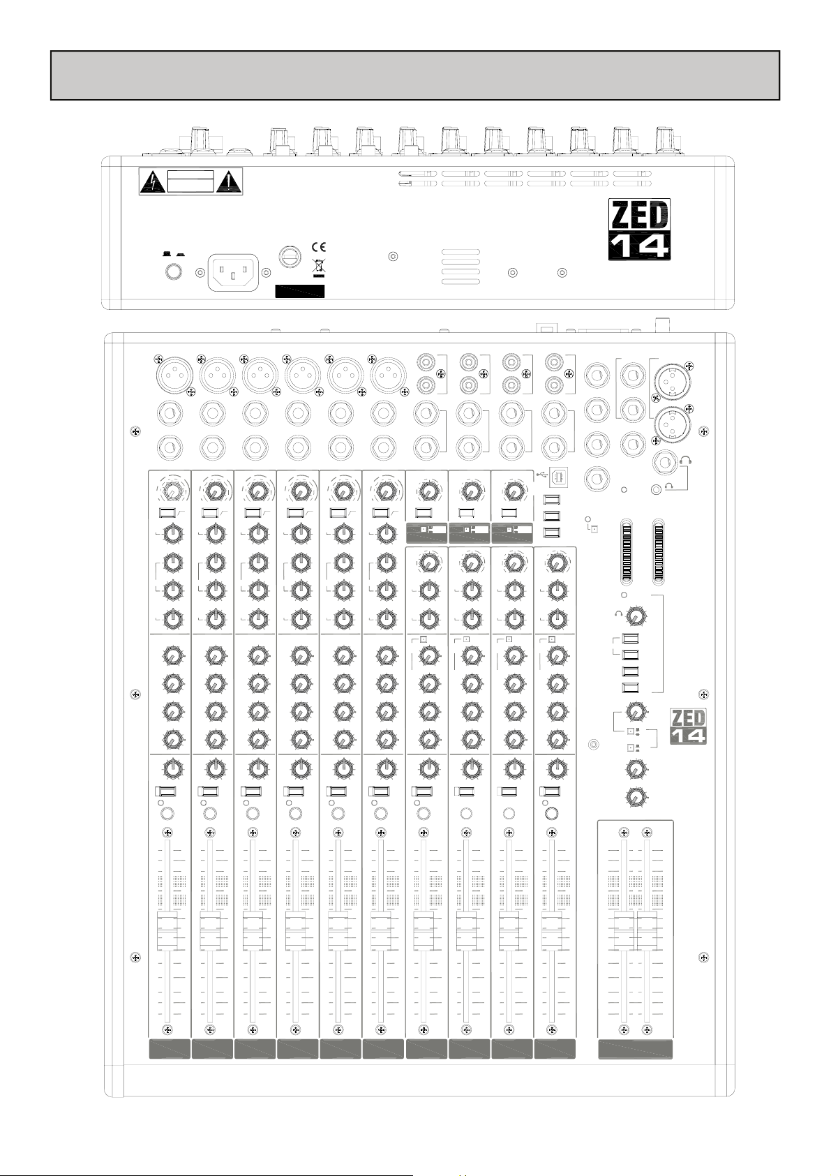
PANEL DRAWINGS
REPLACE FUSE WITH SAME TYPE AND RATING.CAUTION: FOR CONTINUED PROTECTION AGAINST RISK OF FIRE
AC MAINS IN ~
100 - 240V~ 47-63Hz 40W MAX
2
INSERT
0
10
20
30
10
GAIN
0
40
MIC
50
LINE
-6-10 63 26
100Hz
HF
12kHz
+15
-15
650
1k
500
200
2k
3k
120Hz 4k
-15HM+15
LF
80Hz
-15 +15
AUX1
PRE
OO +6
AUX2
PRE
OO +6
AUX3
OO +6
AUX4
POST
OO +6
=
PAN
LR
MUTE
PK !
PFL
This device complies with Part 15 of the FCC Rules.
Operation is subject to the following two conditions:
(1) this device may not cause harmful interference, and
(2) this device must accept a ny interference received,
including interference that m ay cause undesired operation.
FUSE
T630mA L 250V 20mm
Serial No.
3
INSERT
0
10
20
30
10
-6-10 63 26
100Hz
+15
650
1k
OO +6
OO +6
OO +6
OO +6
=
LR
MUTE
PK !
PFL
4
INSERT
0
10
20
30
10
GAIN
0
40
50
2k
3k
MIC
LINE
HF
12kHz
200
LF
80Hz
AUX1
PRE
AUX2
PRE
AUX3
AUX4
POST
PAN
-6-10 63 26
-15
650
500
120Hz 4k
-15HM+15
-15 + 15
OO +6
OO +6
OO +6
OO +6
=
LR
PK !
40
50
100Hz
+15
1k
2k
3k
MUTE
PFL
GAIN
MIC
LINE
HF
12kHz
200
LF
80Hz
AUX1
PRE
AUX2
PRE
AUX3
AUX4
POST
PAN
0
20
10
0
-6-10 63 26
-15
650
500
120Hz 4k
-15HM+15
-15 +15
OO +6
OO +6
OO +6
OO +6
=
LR
MUTE
PK !
PFL
ALLEN&HEATH
30
+15
5
INSERT
10
100Hz
1k
ST RTN
6
ST1 IN
INSERT
0
ST
10
20
10
GAIN
0
40
MIC
50
LINE
-6-10 63 26
HF
12kHz
-15
650
500
200
2k
3k
120Hz 4k
-15HM+15
LF
80Hz
-15 +15
AUX1
PRE
OO +6
AUX2
PRE
OO +6
AUX3
OO +6
AUX4
POST
OO +6
=
PAN
LR
PK !
-5
30
-10
RTN
-20
40
-30
50
OO 10
100Hz
+15
-5
ST1
-10
1k
IN
-20
2k
-30
3k
OO
HF
12kHz
-15 +15
LF
80Hz
-15 +15
STEREO
AUX1
PRE
OO +6
AUX2
PRE
OO +6
AUX3
OO +6
AUX4
POST
OO +6
=
BAL
LR
MUTE
PK !
PFL
2TRK RTN
L
R
L/M
L
R
L/M
ST2 IN
R
0
5
ON
To LR
To 7-8
0
10
MUTE
PFL
R
2TRK
RTN
ST2
IN
5
12kHz
AUX1
AUX2
AUX3
AUX4
-20
-30
-20
-30
HF
LF
80Hz
PRE
PRE
POST
BAL
-10
-10
-15 +15
-15 +15
-5
OO 10
ON
To LR
To 9-10
-5
OO
10
STEREO
OO +6
OO +6
OO +6
OO +6
=
LR
MUTE
PK !
USB
-10
RTN
0
-20
5
-30
ST3
-10
0
IN
-20
5
-30
OO
HF
12kHz
-15 +15
LF
80Hz
-15 +15
AUX1
PRE
AUX2
PRE
AUX3
AUX4
POST
BAL
PFL
CAUTION
RISK OF ELECTRIC SHOCK
DO NOT OPEN
AVIS: RISQUE DE CHOC ELECTRIQUE - NE PAS OUVR IR.
ATTENTION: REMPLACER PAR UN FUSIBLE STRICTEMENT IDENTIQUE EN VALEURS.
WARNING: TO REDUCE THE RISK OF ELECTRIC SHOCK DO NOT EXPOSE THIS APPARATUS TO RAIN OR MOISTURE.
REFER SERVICING TO QUALIFIED SERVICE PERSONNEL.
WARNING: THIS APPARATUS MUST BE EARTHED
OFF
ON
0 I
ENGINEERED IN ENGLAND BY ALLEN & HEATH LIMITED. MADE IN CHINA.
MIC MIC MIC MIC MIC MIC
LINE LINE LINE LINE LINE LINE
1
INSERT
0
10
20
30
10
GAIN
LINE
12kHz
80Hz
AUX1
PRE
AUX2
PRE
AUX3
POST POST POST P OST POST POST POST POST POST POST
AUX4
POST
PAN
0
MIC
HF
-15
500
200
120Hz 4k
-15HM+15
LF
-15 +15
40
50
-6-10 63 26
100Hz
+15
650
1k
3k
OO +6
OO +6
OO +6
OO +6
=
LR
MUTE
PK !
GAIN
0
MIC
LINE
HF
12kHz
-15
500
200
2k
120Hz 4k
-15HM+15
LF
80Hz
-15 +15
AUX1
PRE
AUX2
PRE
AUX3
AUX4
POST
PAN
PFL
REC OUT
L
R
L/M
ST3 IN
R
-5
0
OO 10
ON
To LR
To 11-12
-5
0
10
STEREO
OO +6
OO +6
OO +6
OO +6
=
LR
MUTE
PK !
PFL
ALT OUT
AUX1 OUT
L
R
AUX2 OUT
L/M
AUX3 OUT
ST4 IN
R
AUX4 OUT
USB
ST4
IN
-20
-30
HF
12kHz
LF
80Hz
AUX1
PRE
AUX2
PRE
AUX3
AUX4
POST
BAL
UP=LR post
-5
-10
OO
-15 +15
-15 +15
STEREO
OO +6
OO +6
OO +6
OO +6
=
LR
PK !
AUX1-2
AUX 3-4
LR PRE
10
MUTE
0
SENDRETURN
5
48V
PHANTOM POWER
PHONES
STEREO
AUX1
MASTER
AUX2
MASTER
ALT
OUT
5
5
PFL
INSERT L
INSERT R
MONO OUT
POWER
PFL ACTIVE
MIN MAX
OO +6
LR
OO +6
OO +6
+16
+9
+6
+3
-12
-16
-20
-30
L
0
-3
-6
-9
R
AUX1
AUX2
2TRK RTN
USB RTN
LR
MONITOR
PRE
POST
MAIN OUT
L
R
PHONES
+16
+9
+6
+3
0
ALLEN HEATH
-3
-6
-9
-12
-16
-20
-30
&
0
0
0
10
10
20
30
OO
10
10
5
0
5
5
0
5
10
10
20
20
30
30
OO
10
5
0
5
0
5
10
20
30
OO
OO
10
5
10
20
30
OO
10
5
0
5
5
0
5
10
20
30
OO
10
5
0
5
10
20
30
OO
10
10
5
0
5
10
20
30
OO
0
5
10
20
30
OO
10
5
5
0
5
10
20
30
OO
10
5
0
5
10
20
30
OO
1234567-89-1011-1213-14 RL
Allen & Heath 7 ZED-14, 18 & 24 User Guide
Page 8
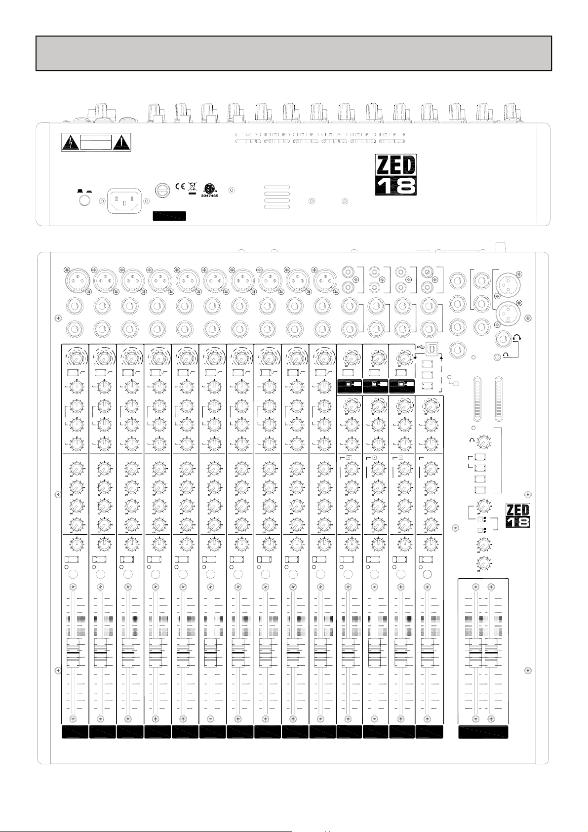
PANEL DRAWINGS
CET APPAREIL DOIT ETRE MIS A LA TERRE
AC MAINS IN ~
100 - 240V~ 47-63Hz 26W
MIC
LINE
2
INSERT
0
10
30
10
GAIN
0
40
MIC
50
LINE
-6-10 63 26
100Hz
HF
12kHz
+15
-15
1k
500
200
2k
3k
120Hz 4k
-15MF+15
LF
80Hz
-15 +15
AUX1
PRE
+6
AUX2
PRE
+6
AUX3
POST
+6
AUX4
POST
+6
PAN
LR
MUTE
PK !
PFL
This device complies with Part 15 of the FCC Rules.
Operation is subject to the following two conditions:
(1) this device may not cause harmful interference, and
(2) this device must ac cept any interference received,
including interference that may cause undesired operation.
REPLACE FUSE WITH SAME TYPE AND RATING.CAUTION: FOR CONTINUED PROTECTION AGAINST RISK OF FIRE
MIC
LINE
3
INSERT
10
20
30
40
50
100Hz
+15
650
1k
2k
3k
+6
+6
+6
+6
=
MUTE
PFL
CAUTION
RISK OF ELECTRIC SHOCK
DO NOT OPEN
AVIS: RISQUE DE CHOC ELECTRIQUE - NE PAS OUVRIR.
ATTENTION: REMPLACER PAR UN FUSIBLE STRICTEMENT IDENTIQUE EN VALEURS.
REFER SERVICING TO QUALIFIED SERVICE PERSONNEL.
WARNING: THIS APPARATUS MUST BE EARTHED
Laite on liitettävä suojamaadoituskoskettimilla varustettuun pistorasiaan
Apparatet må tilkoples jordet stikkontakt
Apparaten skall anslutas till jordat uttag
OFF
ON
0
I
ENGINEERED IN ENGLAND BY ALLEN & HEATH LIMITED. MADE IN CHINA
MIC
LINE
1
INSERT
0
0
10
20
20
30
10
0
-6-10 63 26
-15
650
500
120Hz 4k
-15MF+15
-15 +15
=
LR
PK !
PFL
10
GAIN
0
40
MIC
50
LINE
-6-10 63 26
100Hz
HF
12kHz
+15
-15
650
1k
500
200
2k
3k
120Hz 4k
-15MF+15
LF
80Hz
-15 +15
AUX1
PRE
+6
AUX2
PRE
+6
AUX3
POST
+6
AUX4
POST
+6
=
PAN
LR
MUTE
PK !
GAIN
MIC
LINE
HF
12kHz
200
LF
80Hz
AUX1
PRE
AUX2
PRE
AUX3
POST
AUX4
POST
PAN
GAIN
MIC
LINE
HF
12kHz
200
LF
80Hz
AUX1
PRE
AUX2
PRE
AUX3
POST
AUX4
POST
PAN
T1A L 250V 20mm
0
-15
500
120Hz 4k
-15MF+15
-15 +15
PK !
FUSE
ZED1802
Serial No.
MIC
LINE
4
INSERT
0
10
20
30
10
-6-10 63 26
100Hz
+15
650
1k
+6
+6
+6
+6
=
LR
MUTE
PFL
GAIN
0
40
MIC
50
LINE
HF
12kHz
-15
500
200
2k
3k
120Hz 4k
-15MF+15
LF
80Hz
-15 +15
AUX1
PRE
AUX2
PRE
AUX3
POST
AUX4
POST
PAN
PK !
Cert to CAN/CSA Std. C22.2 No 60065-03
Conforms to ANSI/UL Std. 60065-2003
MIC
LINE
5
INSERT
0
10
20
30
10
GAIN
0
40
MIC
50
LINE
-6-10 63 26
100Hz
HF
12kHz
+15
-15
650
1k
500
200
2k
3k
120Hz 4k
-15MF+15
LF
80Hz
-15 +15
AUX1
PRE
+6
AUX2
PRE
+6
AUX3
POST
+6
AUX4
POST
+6
=
PAN
LR
MUTE
PK !
PFL
ALLEN&HEATH
MIC
MIC
MIC
MIC
MIC
LINE
LINE
LINE
LINE
LINE
6
7
8
9
10
INSERT
0
20
30
10
-6-10 63 26
100Hz
+15
650
1k
+6
+6
+6
+6
=
LR
MUTE
PFL
INSERT
INSERT
0
0
10
10
20
30
10
GAIN
GAIN
0
-6-10 63 26
-15
650
500
120Hz 4k
-15MF+15
-15 +15
=
LR
PK !
0
40
MIC
50
LINE
100Hz
HF
12kHz
+15
-15
1k
500
200
2k
3k
120Hz 4k
-15MF+15
LF
80Hz
-15 +15
AUX1
PRE
+6
AUX2
PRE
+6
AUX3
POST
+6
AUX4
POST
+6
PAN
MUTE
PK !
PFL
40
MIC
50
LINE
HF
12kHz
200
2k
3k
LF
80Hz
AUX1
PRE
AUX2
PRE
AUX3
POST
AUX4
POST
PAN
10
20
30
10
-6-10 63 26
100Hz
+15
650
1k
+6
+6
+6
+6
=
LR
MUTE
PFL
0
20
10
GAIN
0
40
MIC
50
LINE
-6-10 63 26
HF
12kHz
-15
650
500
200
2k
3k
120Hz 4k
-15MF+15
LF
80Hz
-15 +15
AUX1
PRE
AUX2
PRE
AUX3
POST
AUX4
POST
=
PAN
LR
PK !
PFL
INSERT
INSERT
0
10
10
20
30
30
10
GAIN
0
40
40
MIC
50
50
LINE
-6-10 63 26
100Hz
100Hz
HF
12kHz
+15
+15
-15
650
1k
1k
500
200
2k
2k
3k
3k
120Hz 4k
-15MF+15
LF
80Hz
-15 +15
AUX1
PRE
+6
+6
AUX2
PRE
+6
+6
AUX3
POST
+6
+6
AUX4
POST
+6
+6
=
PAN
LR
MUTE
MUTE
PK !
PFL
ST
RTN
-20
-30
ST1
IN
-20
-30
HF
12kHz
LF
80Hz
AUX1
PRE
AUX2
PRE
AUX3
POST
AUX4
POST
BAL
ST RTN
ST1 IN
-5
-10
-5
-10
-15 +15
-15 +15
STEREO
=
LR
PK !
ST 3 IN
-5
-5
=
REC OUT
ON
To LR
To CH
STEREO
MUTE
PFL
ALT OUT
ST4 IN
AUX1 OUT
L
R
AUX2 OUT
L/M
AUX3 OUT
R
L
R
L/M
R
AUX4 OUT
USB
SENDRETURN
0
5
AUX1-2
10
AUX 3-4
48V
LR PRE
PHANTOM POWER
UP=LR post
-5
ST4
-10
0
0
IN
-20
5
5
-30
10
10
HF
12kHz
-15 +15
LF
80Hz
-15 +15
STEREO
AUX1
PRE
+6
+6
AUX2
PRE
+6
+6
AUX3
POST
+6
+6
AUX4
POST
+6
+6
=
BAL
LR
MUTE
PK !
PFL
STEREO
PHONES
ALT
AUX1
MASTER
AUX2
MASTER
OUT
INSERT L
INSERT R
MONO OUT
POWER
+16
L
PFL ACTIVE
MIN MAX
LR
+9
+6
+3
0
-3
-6
-9
-12
-16
-20
-30
AUX1
AUX2
2TRK RTN
USB RTN
+6
LR
MONITOR
PRE
POST
+6
+6
MAIN OUT
L
R
PHONES
+16
+9
+6
+3
0
ALLEN HEATH
-3
-6
-9
-12
-16
-20
-30
R
&
0
0
0
2TRK RTN
L
L
R
R
L/M
L/M
ST 2 IN
R
R
2 TRK
USB
-5
-10
-30
-10
-30
-15 +15
-15 +15
LR
PK !
-10
RTN
0
-20
5
-30
10
ON
To LR
To CH
-5
ST3
-10
0
IN
-20
5
-30
10
HF
12kHz
-15 +15
LF
80Hz
-15 +15
STEREO
AUX1
PRE
+6
AUX2
PRE
+6
AUX3
POST
+6
AUX4
POST
+6
=
BAL
LR
MUTE
PK !
PFL
RTN
0
-20
5
10
ON
To LR
To CH
ST2
0
IN
-20
5
10
HF
12kHz
LF
80Hz
AUX1
PRE
+6
AUX2
PRE
+6
AUX3
POST
+6
AUX4
POST
+6
BAL
MUTE
PFL
10
10
10
10
10
10
10
10
10
10
10
10
10
10
5
5
5
5
5
5
5
5
5
5
5
5
5
5
0
0
0
0
0
0
0
0
0
0
0
0
0
0
5
5
5
5
5
5
5
5
5
5
5
5
5
5
10
10
10
10
10
10
10
10
10
10
10
10
10
10
20
20
20
20
20
20
20
20
20
20
20
20
20
20
30
30
30
30
30
30
30
30
30
30
30
30
OO
OO
OO
OO
OO
OO
OO
OO
OO
OO
OO
O
1
2
3
4
5
6
7
8
9
11-12
10
13-14
OO
15-16
30
OO
30
OO
17-18 RL
10
5
0
5
10
20
30
OO
Allen & Heath 8 ZED-14, 18 & 24 User Guide
Page 9

PANEL DRAWINGS
CAUTION
RISK OF ELECTRIC SHOCK
DO NOT OPEN
AVIS: RISQUE DE CHOC ELECTRIQUE - NE PAS OUVRIR.
ATTENTION: REMPLACER P AR UN FUSIBLE STRICTEM ENT IDENTIQUE EN VALEURS.
WARNING: TO REDUCE THE RISK OF ELECTRIC SHO CK DO NOT EXPOSE THIS APPARATU S TO RAIN OR MOISTURE.
REFER SERVICING TO Q UALIFIED SERVICE P ERSONNEL.
WARNING: THIS APPARATUS MUST BE EARTHED
OFF
ON
0
I
ENGINEERED IN ENGLAN D BY ALLEN & HEAT H LIMITED.
MIC
LINE
1
INSERT
0
10
20
30
10
GAIN
0
40
MIC
50
LINE
-6-10 63 26
100Hz
HF
12kHz
+15
-15
650
1k
500
200
2k
3k
120Hz 4k
-15HM+15
LF
80Hz
-15 +15
AUX1
PRE
OO +6
AUX2
PRE
OO +6
AUX3
POST
OO +6
AUX4
POST
OO +6
=
PAN
LR
MUTE
PK !
This device complies with Part 15 of the FCC Rules.
Operation is subject to the fol lowing two conditions:
(1) this device may not cause harmful interference, and
(2) this device must accept an y interference received,
including interference that may cause undesired operation.
REPLACE FUSE WITH SAME TYPE AND RATIN G.CAUTION: FOR CONTINUED PROTECTION AGAINST RISK OF FIRE
FUSE
T630mA L 250V 20mm
AC MAINS IN ~
100 - 240V~ 47-63Hz 40W MAX
Serial No.
MIC MIC MIC MIC MIC MIC MIC MIC MIC MIC MIC MIC MIC MIC MIC
LINE
LINE
3
2
INSERT
INSERT
0
0
0
10
GAIN
LINE
HF
12kHz
LF
80Hz
AUX1
PRE
AUX2
PRE
AUX3
POST
AUX4
POST
PAN
10
0
MIC
-6-10 63 26
-15
500
200
120Hz 4k
-15HM+15
-15 +15
OO +6
OO +6
OO +6
OO +6
LR
PK !
10
20
30
GAIN
40
50
LINE
100Hz
HF
12kHz
+15
650
1k
2k
3k
LF
80Hz
AUX1
PRE
AUX2
PRE
AUX3
POST
AUX4
POST
=
PAN
MUTE
10
0
MIC
-6-10 63 26
-15
500
200
120Hz 4k
-15HM+15
-15 +15
OO +6
OO +6
OO +6
OO +6
LR
20
20
30
10
GAIN
0
40
MIC
50
LINE
-6-10 63 26
100Hz
HF
12kHz
+15
-15
650
650
1k
500
200
2k
3k
120Hz 4k
-15HM+15
LF
80Hz
-15 +15
AUX1
PRE
OO +6
AUX2
PRE
OO +6
AUX3
POST
OO +6
AUX4
POST
OO +6
=
=
PAN
LR
MUTE
PK !
PK !
ALLEN&HEATH
ST RTN
2TRK RTN
REC OUT
ALT OUT
12kHz
AUX1
AUX2
AUX3
AUX4
ST4
IN
-20
-30
HF
LF
80Hz
PRE
PRE
POST
BAL
UP=LR post
-10
OO
-15 +15
-15 +15
OO +6
OO +6
OO +6
OO +6
LR
PK !
AUX1 OUT
L
R
AUX2 OUT
AUX3 OUT
ST4 IN
R
AUX4 OUT
USB
SENDRETURN
AUX1-2
AUX 3-4
48V
LR PRE
PHANTOM POWER
-5
0
5
10
STEREO
=
MUTE
PFL
L
L
L
R
R
LINE
15
14
13
12
11
10
9
8
7
6
5
4
INSERT
INSERT
0
0
10
10
10
20
20
30
30
30
40
50
100Hz
+15
1k
2k
3k
MUTE
GAIN
GAIN
12kHz
12kHz
AUX1
AUX1
AUX2
AUX2
AUX3
AUX3
AUX4
AUX4
MIC
MIC
LINE
LINE
HF
HF
200
200
LF
LF
80Hz
80Hz
PRE
PRE
PRE
PRE
POST
POST
POST
POST
PAN
PAN
10
10
0
0
-6-10 63 26
-6-10 63 26
-15
-15
500
500
120Hz 4k
120Hz 4k
-15HM+15
-15HM+15
-15 +15
-15 +15
OO +6
OO +6
OO +6
OO +6
OO +6
OO +6
OO +6
OO +6
LR
LR
PK !
PK !
10
GAIN
0
40
40
MIC
50
50
LINE
-6-10 63 26
100Hz
100Hz
HF
12kHz
+15
+15
-15
650
650
1k
1k
500
200
2k
2k
3k
3k
120Hz 4k
-15HM+15
LF
80Hz
-15 +15
AUX1
PRE
OO +6
AUX2
PRE
OO +6
AUX3
POST
OO +6
AUX4
POST
OO +6
=
=
PAN
LR
MUTE
MUTE
INSERT
INSERT
0
0
PK !
10
10
20
20
30
30
40
50
100Hz
+15
650
1k
2k
3k
=
MUTE
GAIN
LINE
12kHz
80Hz
AUX1
PRE
AUX2
PRE
AUX3
POST
AUX4
POST
MIC
HF
200
LF
PAN
10
0
-6-10 63 26
-15
500
120Hz 4k
-15HM+15
-15 +15
OO +6
OO +6
OO +6
OO +6
LR
PK !
10
GAIN
0
40
MIC
50
LINE
-6-10 63 26
100Hz
HF
12kHz
+15
-15
650
1k
500
200
2k
3k
120Hz 4k
-15HM+15
LF
80Hz
-15 +15
AUX1
PRE
AUX2
PRE
AUX3
POST
AUX4
POST
=
PAN
MUTE
INSERT
0
20
30
100Hz
+15
650
1k
OO +6
OO +6
OO +6
OO +6
=
LR
MUTE
PK !
INSERT
INSERT
0
0
10
10
10
GAIN
40
50
LINE
12kHz
2k
3k
80Hz
AUX1
PRE
AUX2
PRE
AUX3
POST
AUX4
POST
PAN
MIC
HF
200
LF
10
0
-6-10 63 26
-15
500
120Hz 4k
-15HM+15
-15 +15
OO +6
OO +6
OO +6
OO +6
LR
PK !
20
20
30
30
40
50
100Hz
+15
650
1k
2k
3k
=
MUTE
10
10
GAIN
GAIN
0
0
40
MIC
MIC
50
LINE
LINE
-6-10 63 26
-6-10 63 26
100Hz
HF
HF
12kHz
12kHz
+15
-15
-15
650
1k
500
500
200
200
2k
3k
120Hz 4k
120Hz 4k
-15HM+15
-15HM+15
LF
LF
80Hz
80Hz
-15 +15
-15 +15
AUX1
AUX1
PRE
PRE
OO +6
OO +6
AUX2
AUX2
PRE
PRE
OO +6
OO +6
AUX3
AUX3
POST POST POST POST POST POST POST POST POST POST
POST
OO +6
OO +6
AUX4
AUX4
POST
POST
OO +6
OO +6
=
PAN
PAN
LR
MUTE
PK !
0
20
30
100Hz
+15
650
1k
=
LR
MUTE
PK !
PFLPFLPFLPFLPFLPFLPFLPFLPFLPFLPFL
INSERT
INSERT
0
GAIN
LINE
HF
12kHz
80Hz
AUX1
PRE
AUX2
PRE
AUX3
AUX4
POST
PAN
MIC
200
LF
120Hz 4k
20
10
0
-6-10 63 26
-15
650
500
-15HM+15
-15 +15
OO +6
OO +6
OO +6
OO +6
=
LR
PK !
0
10
30
10
GAIN
0
40
MIC
50
LINE
-6-10 63 26
100Hz
HF
12kHz
+15
-15
1k
500
200
2k
3k
120Hz 4k
-15HM+15
LF
80Hz
-15 +15
AUX1
PRE
OO +6
AUX2
PRE
OO +6
AUX3
OO +6
AUX4
POST
OO +6
PAN
LR
MUTE
PK !
PFL
10
40
50
2k
3k
INSERT
INSERT
10
20
30
10
GAIN
0
40
MIC
50
LINE
-6-10 63 26
100Hz
HF
12kHz
+15
-15
650
1k
500
200
2k
3k
120Hz 4k
-15HM+15
LF
80Hz
-15 +15
AUX1
PRE
OO +6
AUX2
PRE
OO +6
AUX3
OO +6
AUX4
POST
OO +6
=
PAN
LR
MUTE
PK !
PFL
INSERT
0
0
LINE
HF
LF
80Hz
AUX1
PRE
AUX2
PRE
AUX3
AUX4
POST
PAN
0
MIC
-15
500
200
120Hz 4k
-15HM+15
-15 +15
10
10
20
30
-6-10 63 26
100Hz
+15
650
1k
OO +6
OO +6
OO +6
OO +6
=
LR
MUTE
PK !
PFL
0
10
GAIN
0
40
MIC
50
LINE
-6-10 63 26
HF
12kHz
-15
500
200
2k
3k
120Hz 4k
-15HM+15
LF
80Hz
-15 +15
AUX1
PRE
OO +6
AUX2
PRE
OO +6
AUX3
OO +6
AUX4
POST
OO +6
PAN
LR
PK !
10
20
30
GAIN
40
50
100Hz
12kHz
+15
650
1k
2k
3k
=
MUTE
PFL
L/M
16
ST1 IN
INSERT
R
ST
2TRK
10
-5
20
30
-10
-10
RTN
RTN
0
-20
-20
40
5
-30
50
100Hz
+15
650
1k
3k
=
MUTE
PFL
-30
OO 10
OO 10
ON
To LR
To CH
-5
ST2
ST1
-10
-10
0
IN
IN
-20
-20
2k
5
-30
-30
OO
OO
10
HF
HF
12kHz
12kHz
-15 +15
-15 +15
LF
LF
80Hz
80Hz
-15 +15
-15 +15
STEREO
AUX1
AUX1
PRE
PRE
OO +6
OO +6
AUX2
AUX2
PRE
PRE
OO +6
OO +6
AUX3
AUX3
OO +6
OO +6
AUX4
AUX4
POST
POST
OO +6
OO +6
=
BAL
BAL
LR
LR
MUTE
PK !
PK !
PFL
LINE LINE LINE LINE LINE LINE
LINE
LINE
LINE
LINE
LINE
LINE
R
L/M
L/MRL/M
ST2 IN
ST3 IN
R
USB
-5
-5
-10
RTN
0
0
-20
5
5
-30
OO 10
ON
ON
To LR
To LR
To CH
To CH
-5
-5
ST3
-10
0
0
IN
-20
5
5
-30
OO
10
10
HF
12kHz
-15 +15
LF
80Hz
-15 +15
STEREO
STEREO
AUX1
PRE
OO +6
AUX2
PRE
OO +6
AUX3
OO +6
AUX4
POST
OO +6
=
=
BAL
LR
MUTE
MUTE
PK !
PFL
PFL
MAIN OUT
INSERT L
L
INSERT R
R
MONO OUT
PHONES
POWER
+16
+16
+9
+9
+6
+6
+3
+3
0
0
ALLEN HEATH
-3
-3
-6
-6
-9
-9
-12
-12
-16
-16
-20
-20
-30
-30
L
R
PFL ACTIVE
PHONES
MIN MAX
STEREO
&
AUX1
AUX2
2TRK RTN
USB RTN
ALT
OUT
0
OO +6
LR
MONITOR
PRE
LR
POST
AUX1
MASTER
0
OO +6
AUX2
MASTER
0
OO +6
10
10
10
10
10
10
10
10
10
10
10
10
10
10
10
10
10
10
10
10
5
5
5
5
5
5
5
5
5
5
5
5
5
5
5
5
5
5
0
0
0
0
0
0
5
5
5
5
5
5
5
5
5
5
10
10
10
10
10
10
10
10
20
20
20
20
20
20
20
20
30
30
30
30
30
30
30
30
OO
OO
OO
OO
OO
OO
OO
OO
7
6
5
4
3
2
1
10
10
20
20
30
30
OO
OO
9
8
5
5
5
5
10
10
20
30
OO
10
10
20
20
30
30
OO
OO
11 12 13 14 15 16 17-18 19-20 21-22 23-24 RL
5
10
10
20
20
30
30
OO
OO
0
0
0
0
0
0
0
0
0
0
0
5
5
10
10
20
20
30
30
OO
OO
5
0
0
5
5
10
10
20
20
30
30
OO
OO
10
5
5
0
0
5
5
10
10
20
20
30
30
OO
OO
10
5
0
5
10
20
30
OO
Allen & Heath 9 ZED-14, 18 & 24 User Guide
Page 10

INTRODUCTION TO THE ZED-14 & 24
The following is a technical overview of ZED, if you want to, please skip to the next section.
The Allen & Heath ZED series mixers have been carefully and lovingly designed in the beautiful county of Cornwall in the UK
and is manufactured alongside a wide range of professional audio mixing consoles. Many of the components used in ZED are
exactly the same as in the larger Allen & Heath products and the construction methods are also very similar — utilising individual vertically mounted channel circuit boards with each rotary control fixed with a metal nut to the front panel. This provides a
very robust product that will resist damage and give years of reliable use. It also makes servicing much easier should it be required, with the ability to remove one particular channel from the mixer at a time, or easily change a fader.
The audio circuitry is based on years of continual development and refinement , the performance of all the elements within the
mixer scrutinised and perfected to ensure the very best sound quality possible.
Multi-application:
ZED’s are great for live mixing! Their layout makes them very easy to use and the 100mm faders give much better control of
the mix compared to most products at a similar price.
They are also great for recording, either a live show or an audio project at home can be built up track by track and studio
monitor speakers can be fed from the Alt Outputs.
ZED mixers are also ideal for teaching establishments, houses of worship, hotels and conference centres where their ease of
use and robust qualities make them a top choice.
Mic/Line Pre-amps:
Based on the pre-amps from the PA series, the ZED-14, 18 & 24 pre-amps use a two stage design, with carefully controlled
amounts of gain in each stage. When amplifying the signal from the XLR input, the gain range is huge — 69dB of range to be
exact — and is very evenly distributed around the gain control, meaning better control of signal level. Most of the gain comes
from the first stage, so unwanted noise is kept to a minimum. There is no “pad” switch, or pad circuit — line level signals are
simply plugged into the second stage of the pre-amp by using the line input jack socket. This has the great advantage of lower
noise when using the line input. (It is common to attenuate line level signals, the amplify them back up again which can give
more noise or hiss).
EQ:
The ZED series mixers are equipped with a 3-band equaliser circuit on each mono input and a 2-band EQ on the stereo channels. The frequency and response of each has been carefully chosen to give the maximum performance when using the EQ on a
variety of sources.
AUX system:
Four auxiliary buses are provided, two pre-fade and two post fader. Auxes 1 & 2 have master level controls. The auxes can be
sent to the USB output for either recording or effects purposes and Auxes 1 & 2 can be configured as a stereo pair, with sends
on the stereo channels switched either mono or stereo.
Mono and Stereo Channels:
One of the great things about the ZED series is the number and variety of things you can plug in. In addition to the mono
channels there are four stereo channels, each with a main stereo input on jack sockets, three of them have the ability to take
additional stereo inputs from phono sockets or from the USB audio input, flexibility gives you control.
USB:
Getting audio to and from a computer easily is now a common requirement for live sound and music production. The way we
have implemented this on ZED is super-flexible and super-easy! No longer do you need to fiddle around the back of your computer to get to the soundcard inputs, only to find that the levels are all wrong and noisy. Just plug in a USB lead to your ZED,
select the USB routing on the mixer and the device on your computer and that’s it! Quality audio to and from your PC or
MAC.
As you can tell, we’re very proud of this product we hope you like it too.
Allen & Heath 10 ZED-14, 18 & 24 User Guide
Page 11

SPECIFICATIONS
Operating Levels
Input
Mono channel (XLR) Input +6 to –63dBu for nominal (+17dBu in max)
Mono channel Line Input (Jack socket) +10 to –26dBu (+30dBu maximum)
Insert point (TRS Jack socket) 0dBu nominal +21dBu maximum
Stereo Input (Jack sockets) 0dBu nominal (control = Off to +10dB)
Stereo input (phono sockets) 0dBu nominal (control = Off to +10dB)
Output
L, R & Mono Outputs (L&R XLR, Mono Jack) 0dBu nominal. +21dBu maximum.
Aux Outputs (Jack sockets) 0dBu nominal. +21dBu maximum.
Alt Outputs (phono sockets) 0dBu nominal. +21dBu maximum.
Rec Outputs (phono sockets) 0dBu nominal. +21dBu maximum.
Frequency Response
Mic in to Mix L/R Out, 30dB gain +0.5/-1dB 20Hz to 20kHz.
Line in to Mix L/R out 0dB gain +0.5/-1dB 10Hz to 30kHz
Stereo in to Mix L/R out +0.5/-1dB 10Hz to 30kHz
THD+n
Mic in to Mix L/R Out, 0dB gain 1kHz +10dBu out 0.004%
Mic in to Mix L/R Out, 30dB gain 1kHz 0.014%
Line in to Mix L/R out 0dB gain 0dBu 1kHz 0.005%
Stereo in to Mix L/R out 0dB gain +10dBu 1kHz 0.003%
Headroom
Analogue Headroom from nominal (0Vu) 21dB
USB in & out headroom from nominal (0Vu) 14dB
USB Audio CODEC (Coder/Decoder)
USB Audio In/Out USB 1.1 compliant 16bit.
Sample Rate 32, 44.1, or 48kHz
Noise
Mic Pre EIN @ max gain 150R input Z 22-22kHz -127dBu
Mix L/R out, L/R faders = 0, 22-22kHz ZED-14 -88dBu
Mix L/R out, L/R faders = 0, 22-22kHz ZED-18 -86dBu
Mix L/R out, L/R faders = 0, 22-22kHz ZED-24 -84dBu
Allen & Heath 11 ZED-14, 18 & 24 User Guide
Page 12

Dimensions
ST RTN
2TRK RTN
REC OUT
ALT OUT
AUX1 OUT
INSERT L
PHANTOM POWER
MAIN OUT
L
AUX2 OUT
INSERT R
R
AUX3 OUT
MONO OUT
AUX4 OUT
48V
PHONES
POWER
+16
+16
+9
+9
+6
+6
+3
+3
0
0
ALLEN HEATH
-3
-3
-6
-6
-9
-9
-12
-12
-16
-16
-20
-20
-30
-30
L
R
PFL ACTIVE
&
PHONES
MIN MAX
AUX1
STEREO
AUX2
2TRK RTN
USB RTN
ALT
OUT
0
OO +6
LR
MONITOR
PRE
LR
POST
AUX1
MASTER
0
OO +6
AUX2
MASTER
0
OO +6
10
5
0
5
10
20
30
OO
L
L
R
L/M
R
0
5
ON
To LR
To CH
0
5
10
MUTE
10
5
0
5
10
20
30
OO
L
R
R
L/MRL/M
ST4 IN
ST3 IN
R
USB
USB
-5
SENDRETURN
-10
RTN
0
-20
5
-30
AUX1-2
OO 10
ON
AUX 3-4
To LR
To CH
LR PRE
UP=LR post
-5
-5
ST3
ST4
-10
-10
0
0
IN
IN
-20
-20
5
5
-30
-30
OO
10
OO
10
HF
HF
12kHz
12kHz
-15 +15
-15 +15
LF
LF
80Hz
80Hz
-15 +15
-15 +15
STEREO
STEREO
AUX1
AUX1
PRE
PRE
OO +6
OO +6
AUX2
AUX2
PRE
PRE
OO +6
OO +6
AUX3
AUX3
OO +6
OO +6
AUX4
AUX4
POST
POST
OO +6
OO +6
=
=
BAL
BAL
LR
LR
MUTE
MUTE
PK !
PK !
PFL
PFL
10
10
5
5
0
0
5
5
10
10
20
20
30
30
OO
OO
465mm (18.3 inches)
MIC MIC MIC MIC MIC MIC MIC MIC MIC MIC MIC MIC MIC MIC MIC
MIC
LINE LINE LINE LINE LINE LINE
LINE
LINE
LINE
LINE
LINE
LINE
LINE
LINE
LINE
LINE
10
9
8
7
6
5
4
3
2
1
INSERT
0
10
20
30
10
GAIN
0
MIC
LINE
-6-10 63 26
100Hz
HF
12kHz
-15
+15
650
1k
500
200
120Hz 4k
-15HM+15
LF
80Hz
-15 +15
AUX1
PRE
OO +6
AUX2
PRE
OO +6
AUX3
POST
OO +6
AUX4
POST
OO +6
=
PAN
LR
MUTE
PK !
10
5
10
20
30
OO
1
INSERT
INSERT
0
0
10
10
20
20
30
30
10
10
GAIN
GAIN
0
0
40
40
MIC
MIC
50
50
LINE
LINE
-6-10 63 26
-6-10 63 26
100Hz
100Hz
HF
HF
12kHz
12kHz
-15
-15
+15
+15
650
650
1k
1k
500
500
200
200
2k
2k
3k
3k
120Hz 4k
120Hz 4k
-15HM+15
-15HM+15
LF
LF
80Hz
80Hz
-15 +15
-15 +15
AUX1
AUX1
PRE
PRE
OO +6
OO +6
AUX2
AUX2
PRE
PRE
OO +6
OO +6
AUX3
AUX3
POST
POST
OO +6
OO +6
AUX4
AUX4
POST
POST
OO +6
OO +6
=
=
PAN
PAN
LR
LR
MUTE
MUTE
PK !
PK !
10
10
5
5
5
0
0
0
5
5
10
10
20
20
30
30
OO
OO
3
2
INSERT
INSERT
0
0
0
10
10
10
20
20
20
30
30
30
10
10
10
GAIN
GAIN
GAIN
0
0
0
40
40
MIC
MIC
MIC
50
50
LINE
LINE
LINE
-6-10 63 26
-6-10 63 26
-6-10 63 26
100Hz
100Hz
100Hz
HF
HF
HF
12kHz
12kHz
12kHz
-15
-15
-15
+15
+15
+15
650
650
650
1k
1k
1k
500
500
500
200
200
200
2k
2k
3k
3k
120Hz 4k
120Hz 4k
120Hz 4k
-15HM+15
-15HM+15
-15HM+15
LF
LF
LF
80Hz
80Hz
80Hz
-15 +15
-15 +15
-15 +15
AUX1
AUX1
AUX1
PRE
PRE
PRE
OO +6
OO +6
OO +6
AUX2
AUX2
AUX2
PRE
PRE
PRE
OO +6
OO +6
OO +6
AUX3
AUX3
AUX3
POST
POST
POST
OO +6
OO +6
OO +6
AUX4
AUX4
AUX4
POST
POST
POST
OO +6
OO +6
OO +6
=
=
=
PAN
PAN
PAN
LR
LR
LR
MUTE
MUTE
MUTE
PK !
PK !
PK !
10
5
0
5
10
20
30
OO
4
INSERT
INSERT
0
0
10
10
20
20
30
30
10
10
GAIN
GAIN
0
0
40
40
40
40
MIC
MIC
50
50
50
50
LINE
LINE
-6-10 63 26
-6-10 63 26
100Hz
100Hz
HF
HF
12kHz
12kHz
-15
-15
+15
+15
650
650
1k
1k
500
500
200
200
2k
2k
2k
3k
3k
10
10
5
5
0
0
5
5
10
10
20
20
30
30
OO
OO
5
3k
3k
120Hz 4k
120Hz 4k
-15HM+15
-15HM+15
LF
LF
80Hz
80Hz
-15 +15
-15 +15
AUX1
AUX1
PRE
PRE
OO +6
OO +6
AUX2
AUX2
PRE
PRE
OO +6
OO +6
AUX3
AUX3
POST
POST
OO +6
OO +6
AUX4
AUX4
POST
POST
OO +6
OO +6
=
=
PAN
PAN
LR
LR
MUTE
MUTE
PK !
PK !
10
10
5
5
0
0
5
5
10
10
20
20
30
30
OO
OO
7
6
INSERT
INSERT
0
10
20
30
10
GAIN
0
MIC
LINE
-6-10 63 26
100Hz
HF
12kHz
-15
+15
650
1k
500
200
2k
120Hz 4k
-15HM+15
LF
80Hz
-15 +15
AUX1
PRE
OO +6
AUX2
PRE
OO +6
AUX3
POST
OO +6
AUX4
POST
OO +6
=
PAN
LR
MUTE
PK !
INSERT
0
0
10
10
20
20
30
30
10
10
GAIN
GAIN
0
0
40
40
40
MIC
MIC
50
50
50
LINE
LINE
-6-10 63 26
-6-10 63 26
100Hz
100Hz
HF
HF
12kHz
12kHz
-15
-15
+15
+15
650
650
1k
1k
500
500
200
200
2k
2k
2k
3k
10
5
0
5
10
20
30
OO
8
3k
3k
120Hz 4k
120Hz 4k
-15HM+15
-15HM+15
LF
LF
80Hz
80Hz
-15 +15
-15 +15
AUX1
AUX1
PRE
PRE
OO +6
OO +6
AUX2
AUX2
PRE
PRE
OO +6
OO +6
AUX3
AUX3
POST
POST
OO +6
OO +6
AUX4
AUX4
POST
POST
OO +6
OO +6
=
=
PAN
PAN
LR
LR
MUTE
MUTE
PK !
PK !
10
10
5
5
0
0
5
5
10
10
20
20
30
30
OO
OO
10
9
12
11
INSERT
INSERT
0
0
10
10
20
20
30
30
10
10
GAIN
GAIN
0
0
40
40
MIC
MIC
50
50
LINE
LINE
-6-10 63 26
-6-10 63 26
100Hz
100Hz
HF
HF
12kHz
12kHz
-15
-15
+15
+15
650
650
1k
1k
500
500
200
200
2k
2k
3k
3k
120Hz 4k
120Hz 4k
-15HM+15
-15HM+15
LF
LF
80Hz
80Hz
-15 +15
-15 +15
AUX1
AUX1
PRE
PRE
OO +6
OO +6
AUX2
AUX2
PRE
PRE
OO +6
OO +6
AUX3
AUX3
POST POST POST POST POST POST POST POST POST POST
OO +6
OO +6
AUX4
AUX4
POST
POST
OO +6
OO +6
=
=
PAN
PAN
LR
LR
MUTE
MUTE
PK !
PK !
PFL
PFLPFLPFLPFLPFLPFLPFLPFLPFLPFLPFL
10
10
5
5
0
0
5
5
10
10
20
20
30
30
OO
OO
11 12 13 14 15 16 17-18 19-20 21-22 23-24 RL
L
R
L/M
16
15
14
13
INSERT
0
10
20
30
10
GAIN
0
MIC
LINE
-6-10 63 26
100Hz
HF
12kHz
-15
+15
650
1k
500
200
120Hz 4k
-15HM+15
LF
80Hz
-15 +15
AUX1
PRE
OO +6
AUX2
PRE
OO +6
AUX3
OO +6
AUX4
POST
OO +6
=
PAN
LR
MUTE
PK !
PFL
10
10
20
30
OO
INSERT
INSERT
0
0
0
10
10
20
20
20
30
30
10
10
GAIN
0
40
MIC
50
LINE
-6-10 63 26
HF
12kHz
-15
500
200
2k
3k
120Hz 4k
-15HM+15
LF
80Hz
-15 +15
AUX1
PRE
OO +6
AUX2
PRE
OO +6
AUX3
OO +6
AUX4
POST
OO +6
PAN
LR
PK !
5
0
5
10
GAIN
GAIN
0
0
40
40
MIC
MIC
50
50
LINE
LINE
-6-10 63 26
-6-10 63 26
100Hz
100Hz
HF
HF
12kHz
12kHz
-15
-15
+15
+15
650
650
650
1k
1k
500
500
200
200
2k
2k
3k
3k
120Hz 4k
120Hz 4k
-15HM+15
-15HM+15
LF
LF
80Hz
80Hz
-15 +15
-15 +15
AUX1
AUX1
PRE
PRE
OO +6
OO +6
AUX2
AUX2
PRE
PRE
OO +6
OO +6
AUX3
AUX3
OO +6
OO +6
AUX4
AUX4
POST
POST
OO +6
OO +6
=
=
=
PAN
PAN
LR
LR
MUTE
MUTE
PK !
PK !
PFL
PFL
PFL
10
10
5
5
0
0
5
5
10
10
20
20
30
30
OO
OO
ST2 IN
ST1 IN
INSERT
R
ST
2TRK
10
-5
-5
30
-10
-10
RTN
RTN
0
-20
-20
40
5
-30
-30
50
OO 10
OO 10
ON
100Hz
To LR
To CH
+15
-5
-5
ST2
ST1
-10
-10
1k
0
IN
IN
-20
-20
2k
5
-30
-30
3k
OO
OO
10
HF
HF
12kHz
12kHz
-15 +15
-15 +15
LF
LF
80Hz
80Hz
-15 +15
-15 +15
STEREO
STEREO
AUX1
AUX1
PRE
PRE
OO +6
OO +6
AUX2
AUX2
PRE
PRE
OO +6
OO +6
AUX3
AUX3
OO +6
OO +6
AUX4
AUX4
POST
POST
OO +6
OO +6
=
=
BAL
BAL
LR
LR
MUTE
MUTE
PK !
PK !
PFL
PFL
10
10
5
5
0
0
5
5
10
10
20
20
30
30
OO
OO
ZED-14 385mm (15.2 inches)
ZED-18 464mm (18.3 inches)
ZED-24 645mm (25.4 inches)
0
R2
98
92
43
450
Weight
Unpacked Packed
ZED-14 6.5kg (14.3 lb) 10.5kg (23.1 lb)
ZED-18 8.5kg (18.7 lb) 13kg (28.6 lb)
ZED-24 10.5kg (23.1 lb) 15kg (33 lb)
19” Rack kit for the ZED-14 - Order part number: ZED1402-RK19
19” Rack kit for the ZED-18 - Order part number: ZED1802-RK19
Allen & Heath 12 ZED-14, 18 & 24 User Guide
Page 13

BLOCK DIAGRAM
STEREO CHANNEL 4
ALT OUT
R
L
USB RETURN FROM COMPUTER
RECORD OUT
R
CHAN
LR
STEREO CHANNEL 3
REC OUT
L
GAIN
ON
2 TRK RTN TO MONITOR SELECTION
R
CHAN
LR
STEREO CHANNEL 2
2TRK RTN
L
GAIN
ON
ST1/2/3/4
R
L
GAIN
R
CHAN
LR
SUM
+
STEREO CHANNEL 1
STEREO RETURN
L
GAIN
ON
STEREO CHANNEL
2 BAND EQUALISER
LF
HF
SUM
MUTE
PEAK
PFL
FADER
SUM
SUM
+
+
MIC IN
+
-
LINE IN
+
-
100Hz
INSERT
LF
HM HF
HPF
3 BAND EQUALISER
MUTE
GAIN
MONO CHANNEL
PEAK
PFL
PP
+48V
GLOBAL 48V SWITCH
ZED 14, 18 & 24 BLOCK DIAGRAM
FADER
STEREO
AUX 4
PFL ACTIVE
RECESSED SWITCHES
TO ALT OUT
SUM
+
MONO OUT
MIX POST MONITOR
USB RETURN
2TRK RTN
ALT LEVEL
USB RTN
2 TRK RTN
AUX 1
AUX 2
PFL ACTIVE
PFL/AFL
AUX 2
AUX 3
AUX 3-4
L-R PRE
PRIORITY SWITCHING
RETURN
USB
BAL
AUX 1
AUX 1-2
PRIORITY SWITCHING
USB DEVICE
SOLDER LINK
WIRE PAD
PAN
AUX1
AUX 4
MASTER LEVEL
AUX2
AUX 2
AUX 3
L
R
AUX 1
AUX 2
AUX 3
AUX 4
PFL
RECORD OUT
MASTER LEVEL
AUX1
L INSERT
R INSERT
MAIN LR
FADERS
USB 1 STEREO I/O
HEADPHONES
PHONES
LEVEL
AUX1 OUT
AUX2 OUT
AUX3 OUT
AUX4 OUT
METERS
MAIN OUT
0dBu NOMINAL
L
R
Allen & Heath 13 ZED-14, 18 & 24 User Guide
Page 14

A
MONO INPUT CHANNEL
MIC
LINE
1
INSERT
Mic Input Socket
Standard 3-Pin XLR socket wired as Pin 1=Chassis, Pin 2=hot
(+), Pin 3=Cold (-).
Line Input Jack Socket
Standard 1/4” (6.25mm) Jack socket for balanced or unbalanced line
level signals. Wired Tip=Hot(+), Ring=cold (-), Sleeve=Chassis.
The Line input overrides the Mic input, so if you want to hear
something plugged in to the xlr socket, make sure nothing is
plugged into the Line input.
Insert Jack Socket
Standard 1/4” (6.25mm) Jack socket for unbalanced insert send and
return signals. Wired Tip=send, Ring=return, Sleeve=Chassis.
Nominal level is 0dBu. The insert point is after the 100Hz filter and
before the EQ.
GAIN
LINE
dBr
10.00
0.00
-10.00
-20.00
-30.00
0
20
10
0
MIC
-6-10 63 26
10
30
100Hz
40
50
Gain Control
This adjusts the gain of the input amplifier to match the signal level
of the input. The gain is varied from –6dB (attenuation) to +63dB
for signals plugged in to the xlr socket (Mic Input) and –10dB to
+26dB for signals plugged into the Line input jack.
G
LI
100Hz Hi-pass Filter
The Hi-pass filter is used for reducing pop noise and rumble from microphone signals. It is a 2-pole (12dB per octave) filter with a corner frequency set at 100Hz.
The filter affects signals from both Mic XLR and Line jack
socket.
-40.00
-50.00
10.00 Hz 100.00 1000.00 10000.00 30000.00
Allen & Heath 14 ZED-14, 18 & 24 User Guide
Page 15

MONO INPUT CHANNEL
GAIN
0
MIC
LINE
HF
12kHz
-15
500
200
120Hz 4k
HM
10
0
20
30
10
40
50
-6-10 63 26
100Hz
+15
650
1k
2k
3k
HF EQ
The HF (High Frequency) equaliser affects the frequency response
of the higher audible frequencies. The corner frequency of 12kHz is
around 3dB from the maximum cut or boost of the circuit. It has
plenty of gain and actually gives slightly more that the +/-15dB legend suggests.
dBr
20.00
15.00
10.00
5.00
0.00
-5.00
-10.00
-15.00
-20.00
10.00 Hz 100.00 1000.00 10000.00 30000. 00
MF EQ
The MF (Mid Frequency) equaliser affects the middle of the audible
frequency range. The frequency graduations on the sweep control
are the centre frequencies of the EQ. The range has been carefully
chosen to cover “boomy” frequencies around 120Hz to 250Hz
which may need cutting back, or a lift at 2 to 3kHz may be required
for microphone intelligibility.
-15
+15
LF
80Hz
-15 +15
LF EQ
The LF (Low Frequency) equaliser
affects the response at the low end of
the audio range. The graph shows the
response of the LF EQ at maximum
cut and boost. The corner frequency
is 80Hz.
dBr
20.00
15.00
10.00
5.00
0.00
-5.00
-10.00
-15.00
-20.00
10.00 Hz 100.00 1000.00 10000.00 30000.00
dBr
20.00
15.00
10.00
5.00
0.00
-5.00
-10.00
-15.00
-20.00
10.00 Hz 100.00 1000.00 10000.00 30000.00
Allen & Heath 15 ZED-14, 18 & 24 User Guide
Page 16

MONO INPUT CHANNEL
AUX1
PRE
OO +6
AUX2
PRE
OO +6
AUX3
POST
OO +6
AUX4
POST
OO +6
PAN
LR
PK !
=
MUTE
Auxes 1 & 2
Each of these controls sends a signal to an auxiliary bus. The signal is
sourced pre-fade which means that the level is independent of, and unaffected by the fader. Auxes 1 & 2 are primarily used for foldback monitoring
purposes, as the fader does not affect the level. They can also be used as
feeds for recording and are available sources to the USB interface for this
purpose.
These sends are affected by the Mute switch, so muting the channel will also
mute the Aux sends.
The control varies the signal level to the bus from off (fully attenuated) to
+6dB, with unity gain at the arrow.
There are master level controls for the Aux 1 & 2 outputs situated in the
master section of the mixer.
Auxes 3 & 4
These are post-fade sends, which means that the signals are affected by the
channel fader. Primarily used for effects sends, the aux signal will reduce if
the fader is pulled down so keeping the correct proportion of the effect.
Muting the channel will also mute the Aux sends, and the send controls have
6dB gain fully clockwise.
There are no master level controls for Aux 3 & 4 outputs.
PFL
10
10
20
PAN
The pan control adjusts how the signal from the mono input channel is
shared between the left and right buses and subsequently the main stereo
outputs. Set to the mid position, equal amounts of signal are fed to left and
right, with pan set to L, none is sent to the Right bus.
5
Mute Switch
0
5
This mutes or cuts the signal to the left & right buses and the Aux buses. A
rectangular LED illuminates to show the Mute switch is pressed.
PFL Switch & PK! LED
The PFL (Pre-Fade Listen) switch sends the channel signal to the PFL bus
and subsequently to the headphones and the main L R meters. Used for
checking the audio signal before raising the fader or un-muting the channel.
The PK! LED illuminates dimly to indicate the PFL switch is pressed, and
brightly to indicate the channel signal is within 5dB of clipping.
30
Fader
The 100mm fader affects the level of the channel signal to the left & right
OO
1
Allen & Heath 16 ZED-14, 18 & 24 User Guide
buses and Auxes 3 & 4. There is 10dB of gain at the top and the unity gain
position is marked by “0”.
Page 17

STEREO INPUT CHANNEL ST1
T
ST
RTN
-10
-20
-30
OO 10
ST RTN
ST1 IN
-5
ON
L
R
L/M
R
0
5
Stereo Return Phono sockets
This is an additional stereo input to the main stereo channel input
(below). The gain is varied by the ST RTN control and this input can
be sent to either the stereo channel or straight to the L R main bus,
depending on the setting of the under-panel switch. These inputs
are unbalanced.
Stereo 1 input jack sockets
Standard 1/4” jack sockets for line level stereo signals. Can be used
with a mono input where the L/M input will also connect to the R
input if nothing is plugged in to R.
The Stereo 1 inputs accept unbalanced or balanced signals.
Stereo Return Level control
Adjusts the level of the stereo return input from off (fully attenuated) to maximum where it has 10dB of gain.
Stereo Return ON switch
This switches the signal on when pressed in. Leaving the switch in
the up position is recommended when the stereo return input is
not in use to minimise unwanted noise being passed through.
Stereo Routing selector switch
This switch selects whether the Stereo Return signal is sent to the L
R bus directly, or the stereo channel 1. When it is pressed in, the
Stereo Return signal sums together with the main stereo input.
ST1
-10
IN
-20
-30
HF
12kHz
-15 +15
LF
80Hz
-15 +15
To LR
To 7-8
-5
0
5
OO
10
Stereo 1 Level control
Adjusts the level of the ST1 input. The range is from off to +10dB.
Stereo Channel EQ
The Stereo Channel EQ is 2 band with corner frequencies of 12kHz
for the HF and 80Hz for the LF.
dBr
20.00
15.00
10.00
5.00
0.00
-5.00
-10.00
-15.00
-20.00
10.00 Hz 100.00 1000.00 10000.00 30000.00
Allen & Heath 17 ZED-14, 18 & 24 User Guide
Page 18

E
STEREO INPUT CHANNEL ST1
STEREO
AUX1
PRE
AUX2
PRE
AUX3
POST
AUX4
POST
OO +6
OO +6
OO +6
STEREO Aux 1 & 2 switch
This is an under-panel selector switch that configures Auxes 1 & 2 to be
either mono sends or a stereo send pair.
UP: A mono sum of the left & right stereo channel signal is sent to Aux
buses 1 & 2 by the control knobs.
DOWN: The left stereo channel signal is sent to Aux 1 and the right is
sent to Aux 2 by the control knobs.
Note: This can be useful when setting up a seperate stereo output from
the main L R output using Auxes 1 & 2, possibly for recording. This can be
selected to feed the USB output to create an independent stereo feed for
recording using a computer.
OO +6
BAL
LR
PK !
=
Aux 1 & 2 sends
These control the level of the signals sent to the Aux 1 & 2 buses. The Aux
1 & 2 send controls are configured either as two mono sends or as a stereo
pair depending on the position of the STEREO switch (please see above).
Auxes 1 & 2 are pre-fade, but muted when the Mute switch is pressed.
There is 6dB of gain at the fully clockwise position.
MUT
PFL
Aux 3 & 4 sends
These controls take a mono sum of the left & right stereo channel signals
from after the fader and send them to the Aux 3 and Aux 4 buses respectively. They are muted when the Mute switch is pressed and have 6dB of
gain at maximum.
10
Balance control
5
0
The Balance control varies the relative levels between the left and right
channels.
Mute Switch
5
Mutes the signals to the main L R and the Aux buses.
10
PFL Switch & PK! LED
The Pre-Fade Listen switch takes a mono sum of the stereo channel signals
from before the fader and mute switch. When pressed the signal will appear
on the L R meters and be fed to the headphones circuit for monitoring.
The PK! LED illuminates dimly to indicate the PFL switch is pressed, and
brightly to indicate the channel signal is within 5dB of clipping.
20
30
Fader
The 100mm fader affects the level of the channel signal to the left & right
buses and Auxes 3 & 4. There is 10dB of gain at the top and the unity gain
OO
position is marked by “0”.
7-8
Allen & Heath 18 ZED-14, 18 & 24 User Guide
Page 19
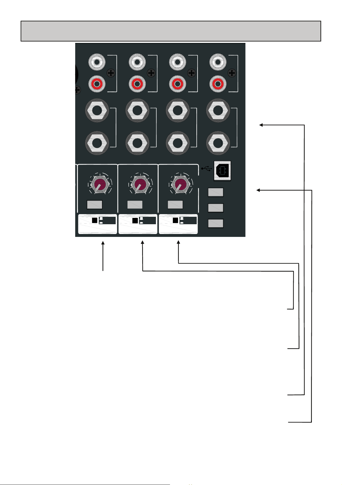
P
STEREO INPUT CHANNELS ST2, 3 & 4 & USB
RT
ST
RTN
-10
-20
-30
ST RTN
-5
OO 10
ON
L
R
L/M
R
0
5
2TRK
RTN
-20
-30
ST2 IN
-5
-10
OO 10
2TRK RTN
L
R
L/M
R
0
5
ON
USB
RTN
-10
-20
-30
REC OUT
ST3 IN
-5
OO 10
ON
L
R
L/M
R
0
5
ALT OUT
L
R
L/M
ST4 INST1 IN
R
USB
SENDRETURN
AUX1-2
AUX 3-4
To LR
To 7-8
To LR
To 9-10
To LR
To 11-12
LR PRE
UP=LR post
Stereo Input Channel ST1
This is stereo input channel ST1 as described on previous pages.
Stereo Input Channel ST2
The only difference from stereo input channel ST1 is the labelling of the additional stereo input on phono connectors, labelled as 2 Track Return. This is to indicate that a 2 track (stereo) input can be inserted here for
playback of a stereo recording or incidental music.
Stereo Input Channel ST3
Stereo input channel ST3 also has an additional stereo input, but instead of being on phono connectors, it
comes from the USB audio input. The level control, ON switch and routing switch are the same as for stereo
input channel ST1. It is best to leave the ON switch in its UP position when the USB input is not in use. The
phono sockets carry the analogue record output signals that are sourced from the main L R outputs. They are
pre-fade, post L R insert.
Stereo Input Channel ST4
Stereo input channel ST4 has one stereo input (ST4) on jack sockets. The phono sockets carry the Alternate
stereo output which comes from the selector switches and level control in the master section.
USB connector & output selection.
A standard USB type B connector plugs in here (cable supplied). The three selector switches determine what is
sent on the USB output. They work on a priority system, so that if more than one is pressed the one nearest
the top takes precedence. So if all 3 are pressed, then the Aux 1 & 2 signals would be sent by the USB device.
Please refer to the section describing using the USB audio port for more details.
Allen & Heath 19 ZED-14, 18 & 24 User Guide
Page 20
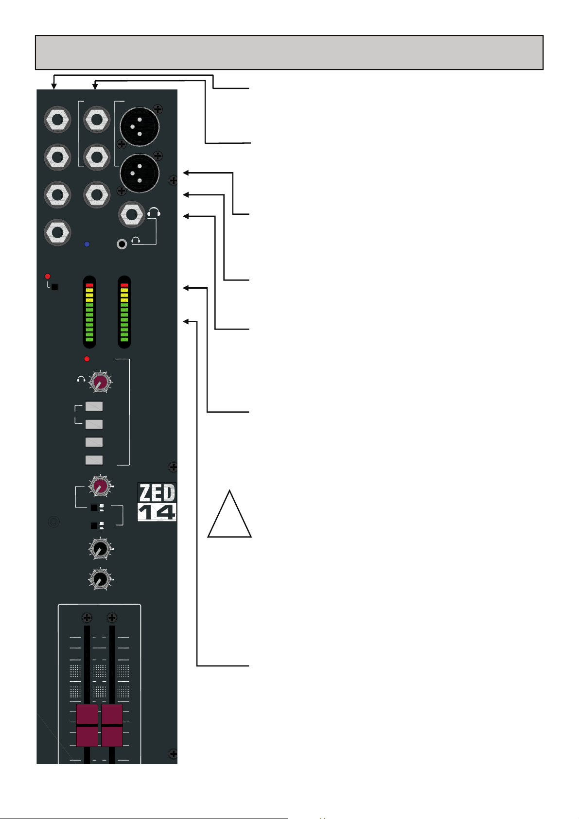
AUX1 OUT
INSERT L
L
MAIN OUT
MASTER SECTION
Aux output jack sockets
Standard 1/4” jack sockets for Aux 1 to 4 outputs. Impedance balanced, nominal level = 0dBu.
AUX2 OUT
AUX3 OUT
AUX4 OUT
48V
PHANTOM POWER
PHONES
STEREO
AUX1
MASTER
AUX2
MASTER
ALT
OUT
LR
INSERT R
MONO OUT
POWER
+16
+9
+6
+3
0
-3
-6
-9
-12
-16
-20
-30
L
PFL ACTIVE
MIN MAX
AUX1
AUX2
2TRK RTN
USB RTN
OO +6
LR
MONITOR
PRE
POST
OO +6
OO +6
Mix L R Insert jack sockets
R
PHONES
Standard 1/4” (6.25mm) Jack sockets for unbalanced insert send and
return signals. Wired Tip = send, Ring = return, Sleeve = Chassis.
Nominal level is 0dBu.
Main L R output xlr sockets
Main left & right outputs. Impedance balanced signals, pin1 = chassis,
pin2 = hot (+), pin3 = cold (-). Nominal level = 0dBu.
+16
+9
+6
+3
0
ALLEN HEATH
-3
-6
-9
-12
-16
-20
-30
R
Mono output jack socket
A mono sum of the main left & right post-fade signals.
Headphones jack sockets
One 1/4” and one 3.5mm jack socket for stereo headphones. Wired
Tip = left, Ring = right, Sleeve = Chassis.
It is recommended that headphones with an impedance higher than
&
30ohms are used.
48v Phantom Power switch
Press this in to switch 48v Phantom Power to all the Mic input xlr
connectors, if any of the microphones attached require power. Dynamic microphones won’t mind being connected to a phantom
powered input, but care is needed to ensure that 48v is not
switched on if an xlr is used to input a signal from an electronic
0
!
0
0
circuit (ie. Another mixer or keyboard).
When switching 48v on or off, or plugging in connectors to
channels with 48v present, it is important (and normal
practise) to mute the channels. This will avoid loud clicks
and bangs potentially getting through to the amps & speakers with the possible effect of damaging the speakers, or
your audience’s hearing!
10
5
Left Right meters
12 segment LED meters, peak type response, the “0” position re-
0
5
10
20
flects 0dBu at the outputs. These display the signals from the monitor selector switches below, or the PFL (pre-fade listen) signals
from any selected channels, which overrides.
Allen & Heath 20 ZED-14, 18 & 24 User Guide
Page 21
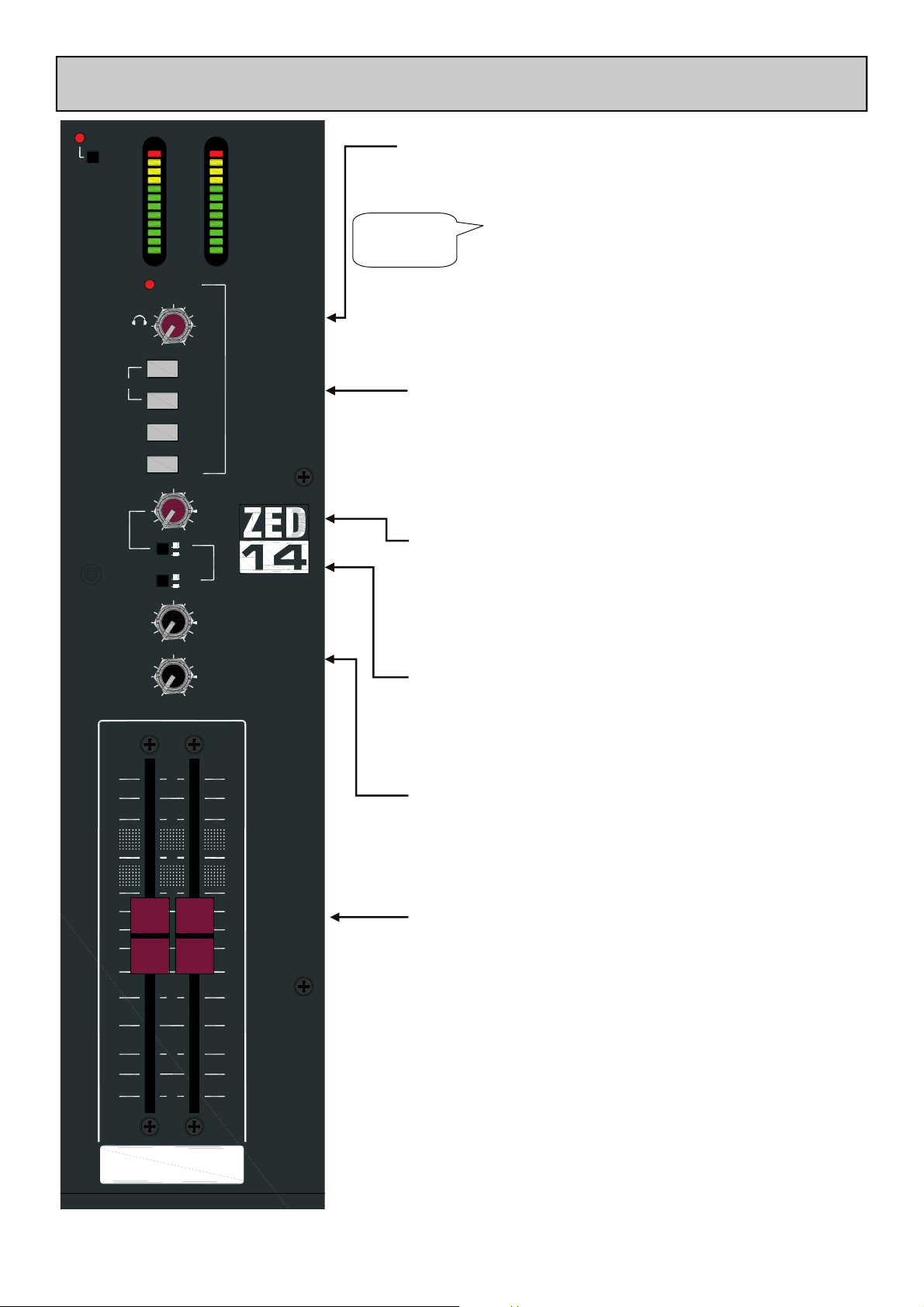
USB & MASTER SECTION
48V
PHANTOM POWER
PHONES
STEREO
ALT
AUX1
MASTER
AUX2
MASTER
MIN MAX
OUT
LR
+16
+9
+6
+3
0
-3
-6
-9
-12
-16
-20
-30
L
PFL ACTIVE
AUX1
AUX2
2TRK RTN
USB RTN
OO +6
LR
MONITOR
PRE
POST
OO +6
OO +6
+16
+9
+6
+3
0
ALLEN HEATH
-3
-6
-9
-12
-16
-20
-30
R
Adjusts the level of the headphone signal.
Warning ! To avoid damage to your
hearing do not operate the headphones
82!
or sound system at excessively high
volume. Continued exposure to high
volume sound can cause frequency
Headphone level control
&
selective or wide range hearing loss.
Monitor selector switches
These 4 switches select the signal source for the headphones monitor and the meters. They work on a priority basis. If they are all up
then the post-fade main L R signals will feed the monitor circuit, if
USB and 2 TRK are pressed, then only the 2 TRK signals will feed
the monitor circuit. The stereo option of pressing both AUX 1 and
AUX 2 together allows Aux 1 to feed the left and Aux 2 to feed the
right monitor circuit. This is useful if a stereo mix is set up using
Auxes 1 & 2.
0
Alternate output level control
The Alt (Alternate) Output is useful for connecting a pair of monitor speakers separate to the main outputs. The level control adjusts
the volume of the output from off to +6dB.
0
Alternate output selector switches
0
These under-panel switches select the signal source for the Alt output. They select between the L R pre-fade, L R post-fade or the
monitor L R signals.
10
5
0
5
Aux 1 & 2 master level controls
For adjusting the level of the Aux 1 and 2 outputs. The range of
level control is from off to +6dB.
Master L R faders
High quality 100mm faders for the main L R outputs. 10dB gain at
10
20
30
OO
RL
the top, unity gain marked at “0”.
Allen & Heath 21 ZED-14, 18 & 24 User Guide
Page 22
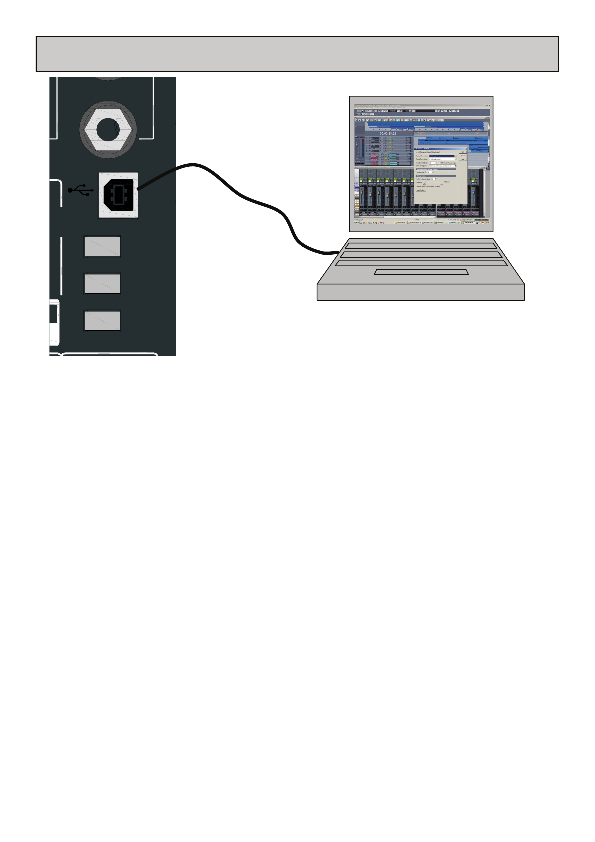
USB CONNECTION
ST4 IN
R
USB
SENDRETURN
AUX1-2
AUX 3-4
2
LR PRE
P
UP=LR post
USB Audio Interface
The ZED is equipped with a stereo bi-directional USB 1.1 compliant audio CODEC. It is fully compliant with USB 2 ports
and uses standard Windows and MAC Core Audio Drivers. In other words, plug it in and your computer will find it and
be able to transfer audio to and from the ZED USB device.
You will need some form of audio software running on your computer to be able to record and play back what you record, but on a basic level, you can use your computers media player to play straight to the ZED device.
Just a couple of points to look out for:
Windows XP/Vista: When you plug in your ZED USB interface to your computer, if the volume level is low or
inaudible, check the device volume in control panel/Sounds and Audio Devices/Volume. Set the volume to High.
Windows 7: At present, Windows 7 treats the USB audio device as a microphone source instead if a line input, so
set the device volume level much lower, we found setting to 3 is ideal.
If you want to reduce latency (delay) there are some different drivers available for your operating system. Please check the
Allen & Heath website www.allen-heath.com for details and links to third party companies able to supply appropriate drivers for your operating system.
Allen & Heath 22 ZED-14, 18 & 24 User Guide
Page 23

cakewalk SONAR X1 LE
DIGITAL AUDIO WORKSTATION
SONAR X1 LE Overview.
SONAR X1 LE is a software application from Cakewalk and is included free of charge with your new ZED mixing console.
SONAR X1 LE is a powerful first step into the world of sequencing and hard disk recording on the Windows platform.
You’ll be able to record from your ZED mixer, create tracks and arrange songs, then play back to your ZED mixer via
the USB port. You can decide whether the SONAR family of products is right for you. If you choose to upgrade your
copy of SONAR X1 LE to a more full-featured version, like SONAR X1 Producer, you’ll now be able to do so at significant savings.
We will describe the basic steps of installing the software and getting started here, for more comprehensive help or
technical support please use the Help files in SONAR X1 LE or visit the SONAR LE website:
www.cakewalk.com/Products/SONARLE/
The website will have details on registering your product and upgrading it should you wish. There are also tutorials to
get you started.
SONAR X1 LE Key Features.
• Powered by SONAR X1
• 32 audio tracks
• 64 MIDI tracks
• 8 simultaneous inputs and outputs
• 24-bit/96 kHz audio quality
• 24 simultaneous effects
• 8 simultaneous virtual instruments
• Integrated VST/VSTi support
• Support for ACID™-format loops
• Support for ReWire clients such as Live or Reason
• Active Controller Technology™ automatically maps MIDI keyboards and control surfaces to the parameters you
need most on effects, instruments, volume, pan, and other mix elements
• Edit MIDI directly from the Track View with the Inline Piano Roll View.
• Support for 32-bit and 64-bit versions of Windows 7, Windows Vista, and Windows XP operating systems
SONAR LE Installation.
Put disk into CD or DVD ROM drive and follow instructions on screen.
Register your copy of SONAR LE by accessing the Cakewalk website. Your SONAR LE software will display
its unique serial number. If the installing computer has access to the internet just click “Register”, if not, use
a different computer to access cakewalk.com and register by typing in the serial number.
Allen & Heath 23 ZED-14, 18 & 24 User Guide
Page 24
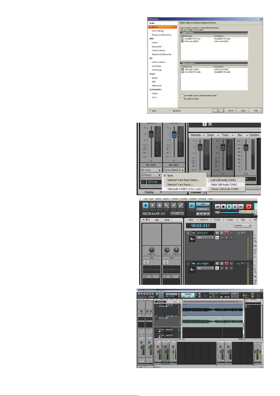
SONAR LE will run automatically after installation, or else
click the icon created on the desktop.
To initially configure SONAR X1 LE with ZED:
Create a normal Cakewalk project (an option offered
when starting SONAR).
In Edit/Preferences configure the I/O—enable the USB
Audio CODEC under Devices. This is the ZED interface.
For now, disable any other devices listed, for example the
computer’s internal soundcard listed here.
In SONAR X1 LE different views are available. The Track
view shows audio and MIDI tracks in a timeline aspect and
the Console view shows a mixer style layout. Different
views can be displayed by the “dock” tabs at the bottom of
the screen. On the left is the Track Inspector.
Add an audio track or two clicking Insert/Audio Track.
Tracks can be named by clicking the name box, here we
have named tracks 1&2 ZED-Left and ZED Right.
Configure the inputs for the tracks using the IN/OUT
routing drop-down menu in the Track Inspector. Here we
select LEFT USB Audio to track 1 and RIGHT USB Audio
to track 2. The track outputs are routed to the Master bus
in SONAR.
Select the output for the Master bus in SONAR by clicking
the drop-down arrow in the Inspector and selecting
STEREO USB Audio CODEC which is the ZED USB return.
In order to check the configuration, enable Input Echo On
(the top right button in the track view header). Play some
audio through your ZED mixer and select the USB send
buttons to the audio signal (for example the L-R mix).
N.B. Do not route the USB return to the L-R mix in your
ZED mixer at this stage—a feedback loop could occur.
You should see the signal on the metering in SONAR LE.
To try a recording, enable the Record buttons on the
tracks and click the main Record button on the transport
toolbar. Recorded audio signal should be displayed in red.
Click stop, or hit the space bar on your keyboard to stop
the recording.
Once you have recorded audio in your SONAR project
you can play it back to the ZED mixer.
De-select the record arm buttons and Input Echo on the
tracks (or you could get both the recorded track signal
AND the live input signal playing, and possibly a feedback
loop).
Press play or hit the spacebar on the keyboard. You should
see the audio being played and levels on the meters in SONAR.
On your ZED mixer, Press USB Rtn ON and turn the level
up to the desired point. Audio should be playing from the
tracks in SONAR to the L-R bus in your ZED.
Allen & Heath 24 ZED-14, 18 & 24 User Guide
Page 25

CONNECTING A ZED TO PRO TOOLS 9 ON A MAC
If you use Pro Tools 9 and want to connect to your ZED console using a Mac computer, here are
some notes:
1. Connect your ZED mixer to your Mac via USB and power on the mixer.
2. With Pro Tools 9 installed, open Audio MIDI Setup on your Mac. PT9 should have created a Pro Tools
Aggregate I/O folder in the Audio Devices list. The ZED interface should appear as USB Audio CODEC in the
list along with other audio devices in your system. Tick Use to enable the device in PT9. You may need to also
tick Resample in order for the audio data settings to be compatible with your PT9 session.
Audio MIDI Setup...
3. Run Pro Tools 9 and create a new session with
at least two audio tracks. Open the SETUP/
Playback Engine window and select Pro Tools
Aggregate I/O as the Current Engine. Click OK.
4. In PT9 click SETUP and then I/O. Select Output from
the menu and the devices available should appear in a box
labelled PTAI/O (Pro Tools Aggregate I/O). Here you can
create a new output path if one doesn’t exist, name it
(here it’s called ZED Stereo OUT) and tick it to enable.
The output path can be set as stereo or mono channels as
is required.
5. Still in I/O Setup, click the Input tab. Again the input
sources should appear for enabled devices in Pro Tools
Aggregate I/O. Create a new path for the inputs and name
as you prefer. Here we have a stereo input named ZEDStereo Input. Note that mono channels can use one
channel of a stereo input path. Make sure the path is
ticked and click OK.
6. Select the inputs and outputs for your tracks in your
session. Here the input for mono Track 1 is selected as
the Left channel from the ZED USB interface. The track
outputs can either be routed to the ZED directly or to a
master bus in Pro Tools and then to the ZED.
7. Finally check the interface and settings are working by recording some audio from the ZED mixer to PT9 and
then play the audio back to the ZED afterwards. Always be wary of audio feedback loops with bi-directional
interface connections which can cause high level audio feedback if signals are routed back to themselves either in
the mixer or in the software system.
Allen & Heath 25 ZED-14, 18 & 24 User Guide
Page 26

L
MAIN PA LINE LEVEL OUT
(LEFT, RIGHT & SUB)
CD
fx
USB CONNECTION
(LINE LEVEL)
STAGE MONITOR SIGNALS
EFFECTS SEND
EFFECTS RETURN (STEREO)
FROM DIRECT BOX
STEREO LINE LEVEL SIGNAL
KEY:
MICROPHONE SIGNAL
Allen & Heath 26 ZED-14, 18 & 24 User Guide
Page 27

RECORDING APPLICATION DIAGRAM
CD
KT-88
fx
EFFECTS RETURN (STEREO)
EFFECTS SEND
CONTROL ROOM MONITORS
ARTISTS MONITOR
USB CONNECTION
STEREO LINE LEVEL SIGNALS
MICROPHONE SIGNAL
KEY:
Allen & Heath 27 ZED-14, 18 & 24 User Guide
Page 28

ST2 INRST3 IN
P
ST4 IN
USING USB FOR EFFECTS
2TRK
RTN
-20
-30
ST2
IN
-20
-30
HF
12kHz
LF
80Hz
AUX1
PRE
AUX2
PRE
-5
-10
OO 10
ON
To LR
To 9-10
-5
-10
OO
-15 +15
-15 +15
STEREO
OO +6
RR
4
3
2
9
10
12
AUX1-2
AUX 3-4
LR PRE
-5
-10
OO
-15 +15
-15 +15
STEREO
OO +6
USB
SENDRETURN
0
5
10
USB
-5
-10
RTN
0
-20
5
-30
ST3
0
IN
-20
5
-30
10
HF
12kHz
LF
80Hz
AUX1
PRE
AUX2
PRE
OO 10
ON
To LR
To 11-12
-5
-10
OO
-15 +15
-15 +15
STEREO
OO +6
0
5
UP=LR post
ST4
0
IN
-20
5
-30
10
HF
12kHz
LF
80Hz
AUX1
PRE
AUX2
PRE
5
6
7
8
OO +6
AUX3
POST POST POST
OO +6
AUX4
POST
OO +6
=
BAL
LR
MUTE
PK !
PFL
10
10
OO +6
AUX3
OO +6
AUX4
POST
OO +6
=
BAL
LR
MUTE
PK !
PFL
10
5
0
5
5
0
5
10
AUX3
AUX4
POST
BAL
PK !
OO +6
OO +6
OO +6
=
LR
MUTE
PFL
10
5
0
5
10
1
11
Use post fade Aux 3 & 4 as the sends from ZED so when you move the channel
fader the effects level stays in proportion.
1
Select Aux 3-4 on the USB output selector switches.
2
USB lead carries the digital signals to & from the computer.
3
Select USB Device Left for Aux 3 or Right for Aux 4 as the input for the track in
the software package.
4
You can use a send bus in software as you would a hardware mixer.
5
Assign an effect from your software plug in list.
6
If using reverb, it’s a good idea to have 100% wet mix level and reduce the predelay in order to compensate for any latency in USB.
7
Send the output of the software group or bus to USB Device. In this case, and
8
probably with most reverbs, it will be stereo so it will go to left & right.
Set the return level and select USB ON. You can monitor the level quickly by se-
9
lecting USB RTN on the headphone monitor selection.
You can select the USB return to use the stereo channel ST3. Or, if using the ste-
10
reo channel for another input route the USB return direct to L-R by leaving this
20
20
20
switch un-pressed.
If you are using the stereo channel ST3 for the USB return signal, then this will be
11
your effects return (Wet mix) fader for the effects to L-R.
30
30
30
You can then add some reverb for example, to your foldback (artists’) monitors.
12
Allen & Heath 28 ZED-14, 18 & 24 User Guide
Page 29

WIRING NOTES
Insert cable wiring
RETURN
SEND
Y-Adapter
2 Outputs to 1 Input
No !
INSERT
R
GROUND
Sleeve=ground
Ring=cold (-)
Tip=hot (+)
T
S
UNBALANCED
BALANCED
RETURN
T
S
R
SEND
T
S
R
LINK RING TO SLEEVE TO UNBALANCE
RCA PHONO CABLE
UNBALANCED
INSTRUMENT CABLE
TRS JACK CABLE
RCA phono jacks
UNBALANCED
BALANCED
PROCESSOR
adapter
Sleeve=ground
Ring=cold (-)
Tip=hot (+)
OUT
IN
Y-Adapter
1 Output to 2 Inputs
Yes
General
Wiring
Information
TO
INPUT
2=hot (+)
3=cold (-)
Tip=hot (+)
2=hot (+)
3=cold (-)
1=ground
Sleeve=ground
Ring=cold (-)
1=ground
BALANCED
XLR MALE
BALANCED
BALANCED
XLR MALE
MIC CABLE
TRS to XLR-F CABLE
TRS to XLR-M CABLE
BALANCED
XLR FEMALE
BALANCED
XLR FEMALE
BALANCED
Sleeve=ground
1=ground
3=cold (-)
1=ground
3=cold (-)
Ring=cold (-)
Tip=hot (+)
2=hot (+)
2=hot (+)
FROM
OUTPUT
Allen & Heath 29 ZED-14, 18 & 24 User Guide
Page 30

PRODUCT SUPPORT
Investigate ALLEN & HEATH’s other ranges at www.allen-heath.com
Large Live Sound mixers — iLive digital and GL Series
Small Format Live Sound mixers — ZED, MixWizards and PA Series
DJ products — Xone Series
Sound Management Series — iDR Series
Registering your product
Thank you for buying the Allen & Heath ZED-14, 18 or 24 mixer. We hope that you are happy with it and that
you enjoy many years of faithful service with it.
Please go to www.allen-heath.com/register.asp and register your product’s serial number and your details. By registering with us and becoming an official Registered User, you will ensure that any warranty claim you might make
is actioned quickly and with the minimum delay.
Alternatively, you may either copy or cut off this section of the page, fill in the details, and return it by mail to:
Allen & Heath Ltd, Kernick Industrial Estate, Penryn, Cornwall TR10 9LU, UK
Allen & Heath 30 ZED-14, 18 & 24 User Guide
Page 31

Page 32

 Loading...