

ALLEN&HEAT XONE464 SERVICE MANUAL
SERVICE MANUAL
For XONE:464 VERSION 1 and VERSION 2
Publication AP3728
Allen & Heath Technical Support
This service manual provides technical information for servicing the XONE:464. It refers
to both the original (VERSION 1) and the revised (VERSION 2) model XONE:464. Whilst
we believe the information presented to be reliable we do not assume responsibility for
inaccuracies. We also reserve the right to make changes in the interest of further product
development.
For further technical support please contact us at Allen & Heath. The contact details are
printed below. To help us provide the most efficient service please quote the console
serial number in any communication regarding this product. Our Internet site provides
further information on our full product range as well as contact details for our distribution
network.
This product complies with the European Electromagnetic
Compatibility directives 89/336/EEC & 92/31/EEC and the
European Low Voltage Directives 73/23/EEC &
93/68/EEC.
This product has been tested to EN55103 Parts 1 & 2 1996 for use in
Environments E1, E2, E3, and E4 to demonstrate compliance with the
protection requirements in the European EMC directive 89/336/EEC.
During some tests the specified performance figures of the product
were affected. This is considered permissible and the product has
been passed as acceptable for its intended use. Allen & Heath has a
strict policy of ensuring all products are tested to the latest safety and
EMC standards. Customers requiring more information about EMC
and safety issues can contact Allen & Heath.
NOTE: Any changes or modifications to the console not approved by
Allen & Heath could void the compliance of the console and therefore
the users authority to operate it.
XONE:464 Service Manual AP3728 Issue 2
Copyright © 2001 Allen & Heath. All rights reserved
The XONE:464 is manufactured in the United Kingdom by:
Kernick Industrial Estate, Penryn, Cornwall, TR10 9LU, UK
Web: http://www.allen-heath.com
Email: sales@allen-heath.com
support@allen-heath.com
spares@allen-heath.com
2 XONE:464 Service Manual

Important Safety Instructions
WARNINGS - Read the following before proceeding :
CAUTION
ATTENTION: RISQUE DE CHOC ELECTRIQUE – NE PAS OUVRIR
Read instructions: Retain these safety and operating instructions for future reference.
Adhere to all warnings printed here and on the console.
Do not remove covers: Operate the console with its covers correctly fitted. Disconnect mains
power by unplugging the power cord if the covers need to be removed
for setting internal options. This work should be carried out by
competent technical personnel only.
Power sources: Connect the console to a mains power only of the type described in
the User Guide and marked on the rear panel. Use the power cord
with sealed mains plug appropriate for your local mains supply as
provided with the console. If the provided plug does not fit into your
outlet consult your service agent for assistance.
Power cord routing: Route the power cord so that it is not likely to be walked on, stretched
or pinched by items placed upon or against it.
Grounding: Do not defeat the grounding and polarisation means of the power cord
plug. Do not remove or tamper with the ground connection in the
power cord.
WARNING: This equipment must be earthed.
Water and moisture: To reduce the risk of fire or electric shock do not expose the console
to rain or moisture or use it in damp or wet conditions. Do not place
containers of liquids on it which might spill into any openings.
Ventilation: Do not obstruct the ventilation slots or position the console where the
air flow required for ventilation is impeded. If the console is to be
operated in a rack unit or flightcase ensure that it is constructed to
allow adequate ventilation.
Heat and vibration: Do not locate the console in a place subject to excessive heat or
direct sunlight as this could be a fire hazard. Locate the console away
from any equipment which produces heat or causes excessive
vibration.
Servicing: Switch off the equipment and unplug the power cord immediately if it
is exposed to moisture, spilled liquid, objects fallen into the openings,
the power cord or plug become damaged, during lightening storms, or
if smoke, odour or noise is noticed.
Installation: Install the console in accordance with the instructions printed in the
User Guide. Do not connect the output of power amplifiers directly to
the console. Use audio connectors and plugs only for their intended
purpose.
XONE:464 Service Manual 3

Important Mains plug wiring instructions.
The console is supplied with a moulded mains plug fitted to the AC
mains power lead. Follow the instructions below if the mains plug has
to be replaced.
The wires in the mains lead are coloured in accordance with the
following code:
TERMINAL
L
N
E
The wire which is coloured Green and Yellow must be connected to
the terminal in the plug which is marked with the letter E or with the
Earth symbol. This appliance must be earthed.
The wire which is coloured Blue must be connected to the terminal in
the plug which is marked with the letter N.
The wire which is coloured Brown must be connected to the terminal
in the plug which is marked with the letter L.
Ensure that these colour codes are followed carefully in the event of
the plug being changed.
Precautions
WIRE COLOUR
European USA/Canada
LIVE BROWN BLACK
NEUTRAL BLUE WHITE
EARTH GND GREEN & YELLOW GREEN
Damage : To prevent damage to the controls and cosmetics avoid placing heavy
objects on the control surface, scratching the surface with sharp
objects, or rough handling and vibration.
Environment : Protect from excessive dirt, dust, heat and vibration when operating,
servicing and storing. Avoid tobacco ash, smoke, drinks spillage, and
exposure to rain and moisture. If the console becomes wet, switch off
and remove mains power immediately. Allow to dry out thoroughly
before using again.
Cleaning : Avoid the use of chemicals, abrasives or solvents. The control panel is
best cleaned with a soft brush and dry lint-free cloth. The faders,
switches and potentiometers are lubricated for life. The use of
electrical lubricants on these parts is not recommended.
Transporting : The console may be transported as a free-standing unit or mounted in
a rack or flightcase. Ensure that the connector pod is secured in place
with the locking screws fitted to prevent movement. Protect the
controls from damage during transit. The faders are best positioned at
the top of their travel if the console is transported without a suitable
flightcase, rack or carton. Use adequate packing if you need to ship
the unit.
4 XONE:464 Service Manual

Contents
Important Safety Instructions ................ 3
Mains Plug Wiring Instructions ............. 4
Precautions ........................................... 4
Welcome to the XONE:464 ................... 6
VERSION 1 and VERSION 2 ................. 7
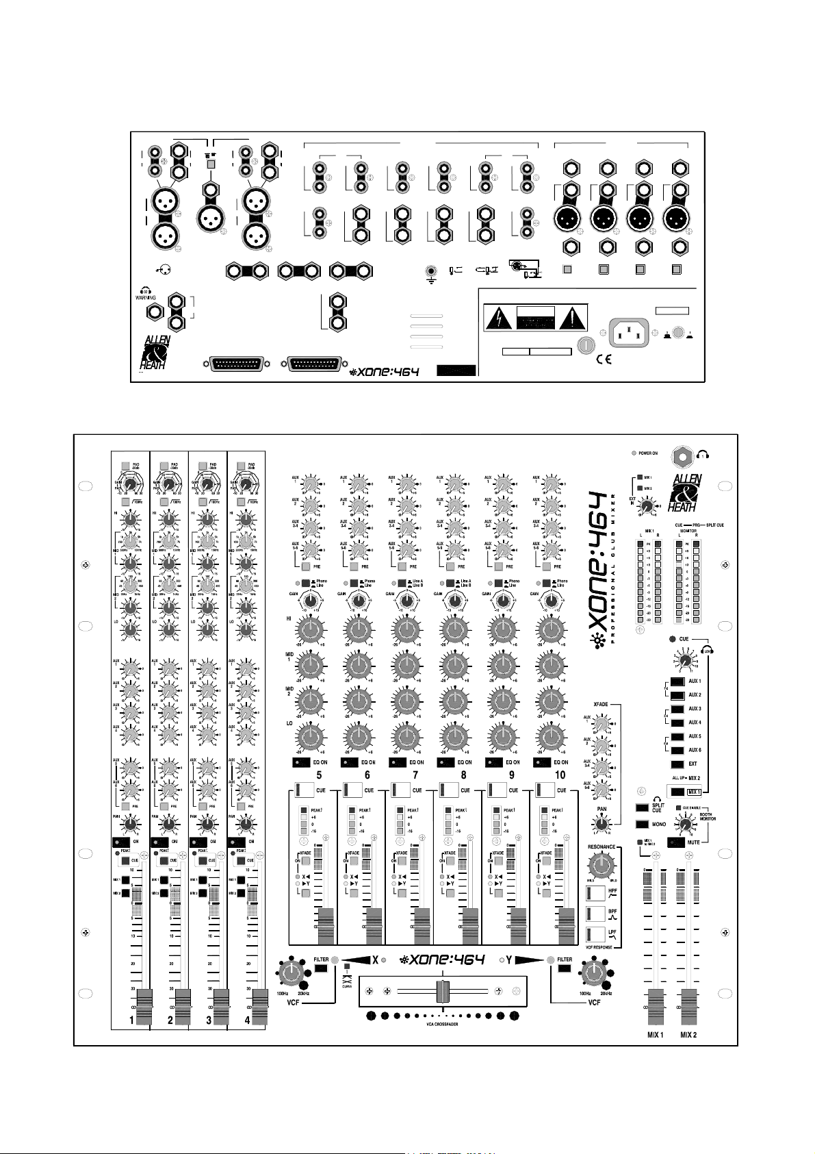
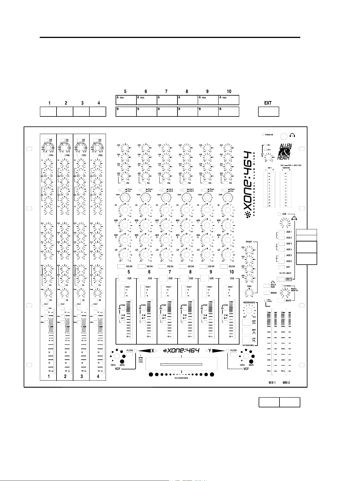
Panel Drawings VERSION 1 ................. 8
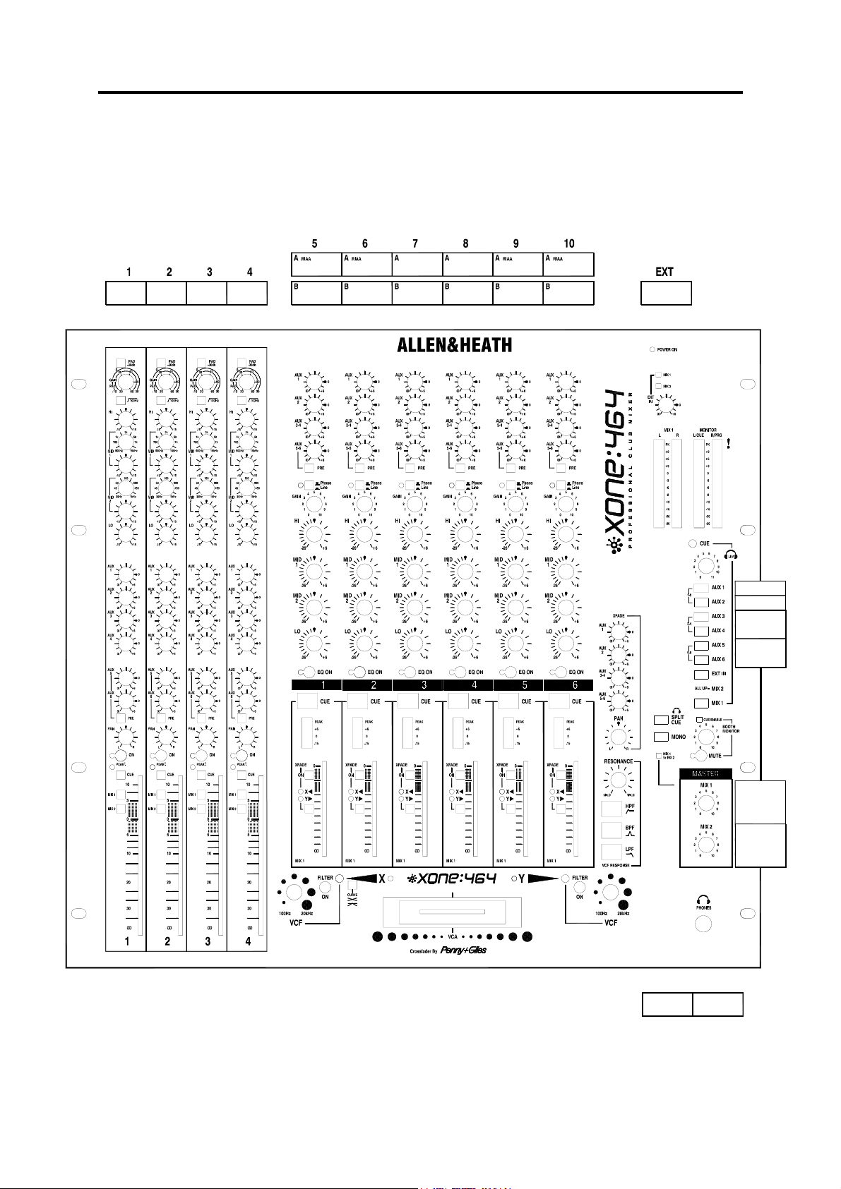
Panel Drawings VERSION 2 ................. 9
Cue Sheet VERSION 1 ........................ 10
Cue Sheet VERSION 2 ........................ 11
Specifications ...................................... 12
Installing the Console.......................... 14
Connecting Mains Power.................... 15
Earthing ............................................... 15
Block Diagram VERSION 1 ................ D1
Block Diagram VERSION 2 ................ D2
MONO INPUT PCB ............................. D3
MONO INPUT Circuit.......................... D4
STEREO INPUT PCB .......................... D5
STEREO INPUT Circuit....................... D6
LEFT PCB ........................................... D7
LEFT Circuit Sheet 1........................... D8
LEFT Circuit Sheet 2........................... D9
RIGHT PCB ....................................... D10
RIGHT Circuit Sheet 1 ...................... D11
RIGHT Circuit Sheet 2 ...................... D12
MASTER PCB ................................... D13
Plugging up the System...................... 16
Cable Wiring Diagrams ....................... 17
Replacing the Crossfader ................... 18
Order Codes........................................ 19
Internal Options................................... 19
Tips and Troubleshooting ................... 20
MASTER Circuit ................................ D14
ROTARY OUTPUT Circuit & PCB ..... D15
CROSSFADE PCB............................ D16
CROSSFADE Circuit Sheet 1 ........... D17
CROSSFADE Circuit Sheet 2 ........... D18
CONNECTOR PCB........................... D19
CONNECTOR Circuit Sheet 1 .......... D20
CONNECTOR Circuit Sheet 2 .......... D21
CONNECTOR Circuit Sheet 3 .......... D22
XONE:464 Service Manual 5

Welcome to the XONE:464
From the User Guide:
The Allen & Heath XONE:464 presents a unique concept in combining a professional live
sound mixer with a serious DJ performance tool in a dedicated club format. And, above
all, it features sound quality second to none. XONE:464 has been designed and
constructed using the same rigorous standards we apply to our large format professional
consoles used and respected by top engineers throughout the world. We have had great
fun designing this new range. We are sure you will get even more enjoyment using it.
MONO Inputs The 4 mic/line inputs are ideal for live performances, or for your MC, DJ
and presenter microphones. An extensive Aux system lets you provide artists with
individual stage monitors, helping them to give their best performance. It can also feed
multiple effects processors such as reverb and delay. A 4 band EQ with swept frequency
mids is the same as that found on top end professional consoles, and helps you deal with
source problems, enhance clarity or sweeten the live mix. Insert jacks let you patch in
channel processors such as compressors to help control the dynamic range of individual
microphones. Smooth 100mm faders with 10dB available boost provide fine precision for
live mixing. Direct outputs are provided for recording, spot effects or channel linking.
STEREO Inputs The 6 dual stereo channels allow selection of up to 12 stereo sources
including 4 RIAA turntables. The 4 band performance EQ gives you a unique extra band
for solid bass control. Boost restricted to 6dB prevents system overload while an
extended cut of up to a massive 26dB provides complete sound sculpturing. Full routing
lets you assign any channel direct to the main mix or through either X or Y crossfader
channels. Large illuminated Cue switches and signal meters keep you in control of your
sources. The Aux system is tucked out of the way of the performance controls and
provides 2 mono and 2 stereo feeds for monitors, effects, recording or additional zones.
EXT Input Provides an additional stereo input to Mix1, Mix2 or both, ideal for stage
reverb returns or sub inputs. Or it can be configured as an external monitor source.
VCA Crossfader Uses a DC voltage to control the audio meaning no clicks, bangs or
crackles as the fader wears. The crossfade curve can be set for either 6dB dip in the
middle, ideal for seamless beat mixing, or for constant level, better suited to scratch
mixing. The fader is removable from the front panel for quick replacement. Crossfader
output can be fed to the Aux system which means that you can provide zone and effects
feeds from your mix. A Pan control provides yet more performance effect.
VCF Filters Unique to XONE, two stereo state variable Voltage Controlled Filters
provide the DJ with a new tool for live performance creativity. These are very similar to
those found on classic analogue synths but benefit from modern, quiet and stable
technology. Use these to sweep the sound by accentuating or cutting frequencies from
100Hz to 20kHz. The 3 filter types HPF, BPF and LPF can be combined to create many
more amazing effects. A large Resonance control changes the ‘Q’ or sharpness of the
filter effect from subtle to extreme. Each VCF has its own in/out switch to toggle the
effect on or off.
MIX Outputs Mix1 and Mix2 are two independent stereo mixes on balanced XLR and
with inserts for patching in limiters and other processors. Use Mix1 for music only and
Mix2 for music + mics, or use them as completely different mixes, ideal when you want to
create separate stage and DJ mixes feeding independent rigs. Both include additional
stereo outputs suitable for recording your mix. A twin connector Mono output sums the L
and R signals from either Mix1 or Mix2 to provide additional mono zone and/or lighting
controller feeds.
MONITOR Section Extensive monitoring is provided so that you can keep a check on
every input and output signal to prevent overload and to cue your mix. A stereo meter
always shows Mix1 output level, another the selected monitor or cue source. An 8 way
switch bank selects which output to monitor, and is automatically overridden by any Cue
pressed. Two pairs of headphones can be plugged in. Split-CUE allows accurate track
matching. An independent stereo Booth Monitor feed includes Cue enable, Mono sum
and Mute functions to satisfy all your monitoring needs.
6 XONE:464 Service Manual

VERSION 1 and VERSION 2 Model Differences
There are minor changes between the original XONE:464 and the revised
model which replaced it in October 2000. This service manual covers both
models. Spares and support are available for both models. When servicing or
ordering spare parts for a XONE:464 first check which model it is.
The original model is referred to as VERSION 1. Its order code is XONE:464/.
Its key identifiers are:
Serial number sequence 020000
Stainless steel panel. Linear MIX master faders.
The newer model is referred to as VERSION 2. Its order code is XONE2:464/.
Its key identifiers are:
Serial number sequence 030000
Painted silver panel. Rotary MIX master controls.
The following is a summary of the differences introduced on VERSION 2:
Styling The original stainless steel finish is replaced with a new textured silver
paint. Several knob and pushbutton types have been changed to further coordinate the styling. There are minor changes to the graphics.
Master Level Controls The original MIX1 and MIX2 master linear faders have
been replaced with rotary master controls.
Crossfader The new high grade Penny & Giles fader is fitted instead of the
original Alps version. These are not interchangeable with VERSION 1.
Headphones Socket The front panel socket has been moved from the top to
lower right.
The circuit information is mostly identical between the two models. Differences
are noted on the diagrams.
XONE:464 Service Manual 7
MIX 2
L
OUT
R
MIX2
L
OUT
R
XLR OUT
12
+OUT
3
- OUT
TIP = L
RING = R
Made in the UK by ALLEN & HEATH
A DIVISION OF HARMAN INTERNATIONAL INDUSTRIES Ltd.
L
INSERT
R
M
OUT
L
LOCAL MONITOR
R
21
L
OUT
R
MIX1
L
OUT
R
AUX6
SYS-LINK OUT
(option)
MIX
1
AUX
L
10
INSERT
A
IN
L
R
R
B
IN
L
R
AUX
AUX54 AUX
32
EXT IN
USER OPTIONS
VERSION 1
9
RIAA
A
IN
L
R
B
IN
L/M
R
AUX
L/M
R
STEREO INPUTS
8
A
IN
L
R
B
IN
L/M
R
A
IN
L
R
B
IN
L/M
R
1
SERIAL No:
7
6
RIAA
LINE IN/OUT
A
IN
L
R
B
IN
L/M
R
TIP +TIP
RING -RING
A
IN
L
R
B
IN
L
R
INSERT
1
2
SEND
TIPTIP
3
RINGRING
RETURN
INPUT
TO REDUCE THE RISK OF FIRE OR ELECTRIC SHOCK
DO NOT EXPOSE THIS APPARATUS TO RAIN OR MOISTURE.
AVIS: RISQUE DE CHOC ELECTRIQUE - NE PAS OUVRIR.
100 - 240V~ T500mA 250V 20mm
WARNING: FOR CONTINUED PROTECTION AGAINST RISK OF FIRE
REPLACE FUSE WITH SAME TYPE AND RATING
ATTENTION: REMPLACER LE FUSIBLE AVEC UN DES MEMES CARACTERISTIQUES.
5
+IN
- IN
CAUTION
4
INSERT
IN
4
DIR
OUT
4
TIP +INTIP
RINGRING -IN
FUSE
MONO INPUTS
3
INSERT
INSERT
IN
IN IN
3 21
DIR
DIR
OUT
OUT
2
3
MIC 4
MIC 4
+48V
+48V
WARNING - THIS APP ARATUS MUST BE EARTHED.
AC MAINS IN ~
REFER TO USER GUIDE BEFORE CONNECTING SUPPLY
NO USER SERVICEABLE PARTS INSIDE.
REFER SERVICING TO QUALIFIED SERVICE PERSONNEL.
2
MIC 4
+48V
SUPPLY VOLTAGE RANGE:
100 - 240V
1
INSERT
DIR
OUT
1
PHANTOM POWER
47-63Hz ~ 30W MAX
OFF
MIC 4
+48V
~
ON
8 XONE:464 Service Manual
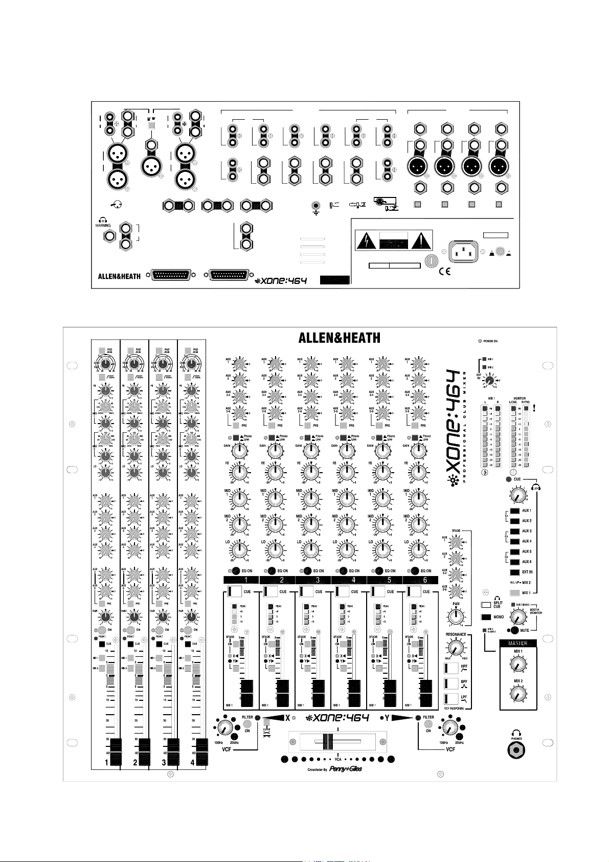
VERSION 2
MIX 2
L
OUT
R
MIX2
L
OUT
R
XLR OUT
2
1
+OUT
3
- OUT
TIP = L
RING = R
Made in the UK by
A DIVISION OF HARMAN INTERNATIONAL INDUSTRIES Ltd.
L
INSERT
R
M
OUT
L
LOCAL MONITOR
R
21
L
OUT
R
MIX1
L
OUT
R
6
AUX
SYS-LINK OUT
(option)
MIX
AUX
1
5 4
INSERT
L
R
AUX
10
RIAA
AIN
L
R
INB INB
L
R
32
AUX
AUX
EXT IN
L/M
R
USER
INA
INB INB
1
L
R
L/M
R
STEREO INPUTS
8
SERIAL No:
7
INA
L
R
L/M
R
6
RIAA
INA INA
L
R
INB INB
L/M
R
LINE IN/OUT
TIP +TIP
RING -RING
L
R
L
R
INSERT
1
2
SEND
TIPTIP
3
RINGRING
RETURN
INPUT
TO REDUCE THE RISK OF FIRE OR ELECTRIC SHOCK
DO NOT EXPOSE THIS APPARATUS TO RAIN OR MOISTURE.
AVIS: RISQUE DE CHOC ELECTRIQUE - NE PAS OUVRIR.
100 - 240V~ T500mA 250V 20mm
WARNING: FOR CONTINUE D PROTECTION AGAIN ST RISK OF FIRE
REPLACE FUSE WITH SAME TYPE AND RATING
ATTENTION: REMPLACER LE FUSIBLE AVEC UN DES MEMES CARACTERISTIQUES.
9
INA
L
R
L/M
R
AUX
5
+IN
- IN
CAUTION
4
INSERT
IN
4
DIR
OUT
4
TIP +INTIP
RINGRING -IN
FUSE
MONO INPUTS
3
2
OUT
INSERT
IN
2
DIR
2
INSERT
IN
1
DIR
OUT
1
MIC 2
+48V
SUPPLY VOLTAGE RANGE:
100 - 240V
47-63Hz ~ 30W MAX
OFF
INSERT
IN
3
DIR
OUT
3
MIC 3
MIC 4
+48V
+48V
WARNING - THIS APPARATUS MUST BE EARTHED.
AC MAINS IN ~
REFER TO USER GUIDE BEFORE CONNECTING SUPPLY
NO USER SERVICEABLE PARTS INSIDE.
REFER SERVICING TO QUALIFIED SERVICE PERSONNEL.
1
PHANTOM POWER
~
MIC 1
+48V
ON
XONE:464 Service Manual 9
XONE:464 VERSION 1 - CUE SHEET
Photocopy and use to log your console settings
10 XONE:464 Service Manual
XONE:464 VERSION 2 - CUE SHEET
Photocopy and use to log your console settings
XONE:464 Service Manual 11

Specifications
0dBu = 0.775 Volts rms +4dBu = 1.23V rms
0dBV = 1 Volt rms -10dBV = 316mV rms
Maximum output level XLR +26dBu into >2k ohm load
TRS jack +21dBu into >2k ohm load
RCA phono +15dBu into >10k ohm load
Internal headroom Channels +21dB
Mix to output +23dB
Peak indicators Turn on 9dB before clipping
Meters MIX1 / MONITOR Peak reading 12 led 3 colour
Frequency response +0/-1dB 20Hz to 40kHz
Distortion < 0.006% THD+noise measured at +14dBu 1kHz
Crosstalk < 90dB Channel shutoff measured at 1kHz
Noise Measured rms 22Hz to 22kHz
MIC EIN -128dB referred to 150 ohm source
Residual output noise XLR -90dBu (-94dB S/N)
TRS jack -84dBu (-84dB S/N)
RCA phono -92dBu (-84dB S/N)
Mix noise, ch routed XLR -86dBu (-90dB S/N)
TRS jack -83dBu (-83dB S/N)
RCA phono -91dBu (-83dB S/N)
Power Supply
Internal switch mode power unit with auto sensing mains input.
MAINS IN socket IEC 3 pin
Power lead Country dependent with moulded mains plug supplied
AC mains 100 to 240V AC @ 50/60Hz
Consumption 30W max
Mains fuse rating 100-240V AC T500mA 20mm
Dimensions and Weights
The connector pod can be rotated and fixed in one of two positions to allow either
desktop operation with rear facing connectors, or 19” rack mounting with underside
connectors in 10U space.
Width Height Depth
Desktop 483mm (19”) 192mm (7.6”) 530mm (20.9”)
Rack mounted 483mm (19”) 444mm (17.5”) 10U 135mm (5.3”)
Packed 590mm (23.2”) 260mm (10.2”) 610mm (24”)
Unpacked Packed
Weight 10kg (22lbs) 13kg (29lbs)
12 XONE:464 Service Manual

Connector Types
XLR connections are Pin 2 = hot (+) Pin 3 = cold (-) Pin 1 = GND
TRS input and output connections are Tip = hot (+) Ring = cold (-) Sleeve = GND
TRS insert connections are Tip = SEND Ring = RETURN Sleeve = GND
Input Connections
CH 1-4 in (XLR) Balanced XLR female 2k ohm -60 to –20dBu PAD out
>10k ohm -30 to +10dBu PAD in
CH 1-4 in (TRS) Balanced TRS jack >10k ohm -30 to +10dBu
CH 5,6,9,10 in A RCA phono RIAA 47kohm/330pF 2 to 100mV
CH 7,8 in A RCA phono >10k ohm -10 to +10dBu
CH 5,10 in B RCA phono >10k ohm -10 to +10dBu
CH 6,7,8,9 in B Balanced TRS jack >10k ohm -10 to +10dBu
EXT in Balanced TRS jack > 10k ohm -10dBV (+4dBu option)
Inserts
CH 1-4 Unbalanced TRS jack SEND/RET <75/>3k ohm 0dBu
MIX out 1,2 Unbalanced TRS jack SEND/RET <75/>3k ohm -2dBu
Output Connections
DIR out 1-4 Impedance balanced TRS jack <75 ohm 0dBu
MIX out 1,2 (XLR) Balanced XLR male <75 ohm +4dBu
MIX out 2 (RCA) RCA phono <75 ohm -10dBV
MONO out (XLR) Balanced XLR male <75 ohm +4dBu
MONO out (TRS) Impedance balanced TRS jack <75 ohm -2dBu
AUX out 1-6 Impedance balanced TRS jack <75 ohm -2dBu
LOCAL MON out Impedance balanced TRS jack <75 ohm -2dBu
Headphones 1,2 Tip = L Ring = R 30 to 600 ohm recommended
XONE:464 Service Manual 13
 Loading...