


OPERATOR’S
MANUAL
REVISED 9-4-6 for Version 3 build 27
http://www.allendatagraph.com/

Limited Warranty Agreement........................................................... 1
Technical Support............................................................................. 1
Installation........................................................................................2
SET-UP.......................................................................................................... 2
i-TECH Cutter Stand..................................................................................... 2
Computer Connection.................................................................................... 2
Communications Port Setup................................................................................3
Setup for Window XP............................................................................................................3
Setup for Windows 2000.......................................................................................................4
Setup for Windows 95/98......................................................................................................6
Loading Allen i-TECH Software .................................................................. 7
The Remote Panel Utility Program......................................................................7
XP Installation Instructions ...................................................................................................7
Other Windows Operating Systems Installations..................................................................7
Installing Firmware..............................................................................................7
Windows XP / Windows 2000 Driver.................................................................8
Optional SmartMarkTM Sensor......................................................... 9
Registration Mark.......................................................................................... 9
Operation..................................................................................................... 10
SmartMark™ Setup...................................................................................... 11
Sensitivity ..........................................................................................................11
Sensor Offsets....................................................................................................12
Control Panel..................................................................................14
Remote Panel.................................................................................. 18
Remote Panel Functions.............................................................................. 18
Action menu ................................................................................................ 18
Send HPGL File.................................................................................................18
Cancel, Continue, Pause ....................................................................................18
Save Settings from Cutter to File, Load Settings from File To Cutter..............18
Save Calibration/Restore Calibration................................................................18
Open Com Port ..................................................................................................19
Close Com Port..................................................................................................19
Upload Firmware...............................................................................................19
Save to EEROM and Restore from EEROM.....................................................19
Setup Menu.................................................................................................. 19
Main Menu.........................................................................................................19
State Tab..............................................................................................................................19
Knife Settings Tab...............................................................................................................20
Rubber Tab ..........................................................................................................................20
Line Sensor........................................................................................................21
Line Sensor Tab...................................................................................................................21

Skew Tab.............................................................................................................................23
Scale Tab .............................................................................................................................24
Settings Menu....................................................................................................24
Options Menu ....................................................................................................27
Dynamic Force Adjust.......................................................................................28
Diagnostics.................................................................................................. 29
Joy Stick ...................................................................................................... 29
i-TECH Cutter Loading Instructions.............................................. 29
Installing Knife Blades...................................................................30
Tutorial Using Adobe Illustrator and SmartMarkTM.......................31
Calibration......................................................................................33
Maintenance ................................................................................... 34
Cleaning....................................................................................................... 34
Pinch Wheel Maintenance ........................................................................... 34
Mechanical Adjustments............................................................................. 34
Belt Tension.......................................................................................................34
Diagnostics..................................................................................... 35
Diagnostic Operation................................................................................... 36
Control panel operation .....................................................................................36
Remote panel operation.....................................................................................36
Setup Diagnostics........................................................................................ 36
Customer Diagnostics.................................................................................. 37
Set Model Number 03........................................................................................37
Button Diagnostic 31.........................................................................................37
Confidence Test 02............................................................................................37
Flag Monitor / Adjust 34 ...................................................................................38
Flag Setup - Z Axis 58.......................................................................................38
LED and Hex display 29....................................................................................38
Line Sensor 21...................................................................................................38
Motor Balance 51...............................................................................................38
PWM Amplifier Status ......................................................................................39
Reed Switch 24..................................................................................................39

Trouble Shooting............................................................................ 39
Error Codes..................................................................................... 40
Appendix A Installation And Assembly Instructions..................... 41
Appendix B SmartMarkTM setup.................................................... 41
Appendix C Loading Diagram ....................................................... 41
Appendix D Cart Assembly Instructions........................................ 41
Appendix E Radio and Television Interference..............................42
Appendix F Model i-536 Addendum.............................................. 42
Appendix G Model i-536 Adjustable Parameters........................... 42
Appendix H Hot Tip Instructions...................................................42
Appendix I Template Maker Supplement.......................................42

Limited W arranty Agreement
ALLEN DATAGRAPH i-TECH cutters are warranted to be free of defects in both materials and
workmanship. Should any part of this equipment be defective, it will be repaired or replaced, at the
option of the manufacturer, at no charge for parts or factory labor for a period of one (2) years from
the date of installation. All warranty services are performed at the Allen Datagraph factory. Replacement parts not installed at the factory will be billed to the customer at regular prices and credit
will be issued when the defective parts are returned. The customer is responsible for freight on warranty parts and repairs.
This warranty is void if:
1. The equipment has been damaged by negligence, accident or mishandling, or has not been
operated in accordance with the procedures described in the operating instructions;
or:
2. The equipment has been altered or repaired by other than an approved service station or
factory service center, or adaptations or accessories have been attached to the equipment that shall
have adversely affected the performance, safety, or reliability of the equipment.
NO OTHER WARRANTY, EXPRESSED OR IMPLIED, APPLIES to the equipment. Allen
Datagraph does not assume any responsibility for consequential damages occasioned by the
equipment, or inconvenience or interruption in operation.
In case of unsatisfactory operation, Allen Datagraph or its Dealer should be notified immediately.
Technical Support
Up to 4 hours of call in technical support is available at no charge during the warranty period.
Technical support is available during business hours based on Eastern Time Monday thru Friday.
Technical support outside the limits stated will be billed at current rates.
For Technical support call: 603-216-6344
There are many online documents available to help you to use the Cutter at our technical support
page at
http://www.allendatagraph.com.
1
Installation
SET-UP
Some Allen Datagraph products require specialized installation in order for the limited warranty to
remain in effect, ask your dealer or contact technical support at Allen Datagraph for details.
Unpack all accessories and the unit. See installation and assembly instructions in Appendix A.
Power Connection
Important Note: Use of a HIGH QUALITY surge protector or uninterruptible power supply is
REQUIRED by Allen Datagraph Systems. Failure to do so could affect your warranty coverage if a
problem arises due to improper power connection.
CAUTION: The power cord is a three-conductor cable that incorporates a safety (earth) ground
connection. For the machine to operate safely and correctly, the power cord must be plugged into
an outlet that has an earth ground contact. Never plug the power cord into a two-prong outlet by
using a 3=2 cord adapter.
CAUTION: Never allow roll or sheet goods to rub on the power cord because the material can cut
the cord causing an electrical fire hazard!
Allen Products can be configured to operate from any of the following power sources:
115 VAC / 48-66 Hz or 230 VAC / 48-66 Hz
ALLEN DATAGRAPH products are normally factory preset for the power requirements of the
destination country. The machine's configuration is indicated on the power input module as either
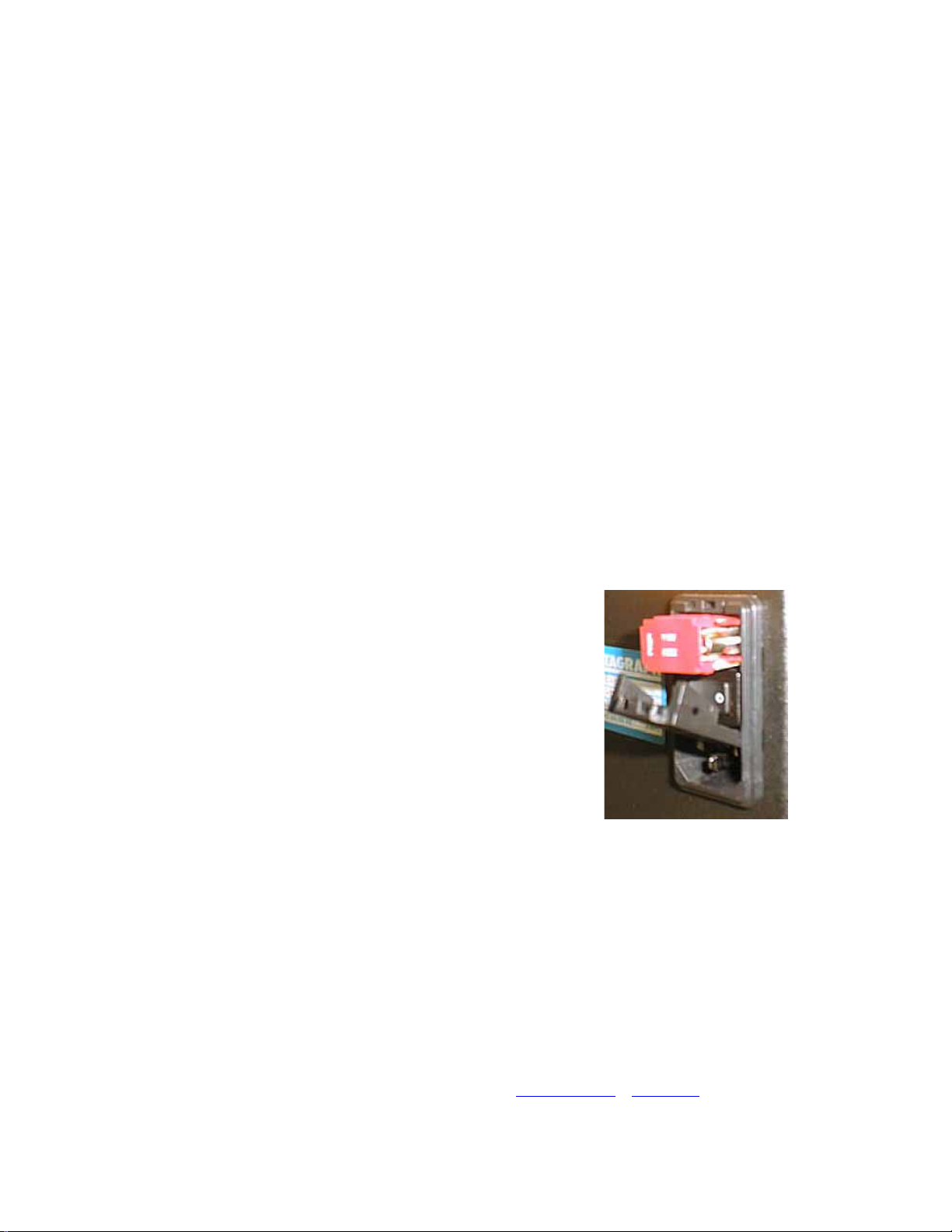
115V or 230V. To change the configuration:
a. Disconnect the AC power cord from the fuse
block on the power input end panel. This is
located at the lower left end of cutter.
b. Open the fuse block cover with a small flat
screwdriver and remove the red fuse block.
c. Orient the fuse block so that the desired voltage
appears in the fuse block cover.
d. Close the fuse block cover and verify that the
desired voltage is showing.
i-TECH Cutter Stand
The i-TECH CUTTER comes equipped with a deluxe stand. Assembly instructions for the stand
are packaged inside the stand box that arrived with your cutter.
Note: The material rollers and associated brackets are packaged inside the cutter box, under the
packaging foam. It is necessary to remove the foam in order remove the parts.
Computer Connection
System Interfacing
All Allen Datagraph products utilize serial (RS-232) interface or optionally USB (universal serial
bus) interface. Use of the USB requires a USB to Serial converter. The recommended USB to
serial converters are described in Title: Usb Interface
support page of the Allen Datagraph web site.
Website Copy / CD Copy on the technical
2

The serial interface is factory preset for 9600 baud, no parity, 8 bits, 1 stop bit. The i-TECH, when
used with the supplied plotter cable, automatically supports both HARDWIRE and XON / XOFF
software handshaking.
Connect the plotter cable supplied with the i-TECH to serial port and to the communications port
on the host computer. A "null modem" cable may be used on serial XON / XOFF communications
only and is available at computer supply stores.
Because of the high degree of bi-directional communications required by the i-TECH and the
SmartMark™ system we recommend the use of the supplied communications cable and one of the
com ports on the host computer.
See your computer documentation for proper set-up of the communications port.
In general the communications port should be set up as follows:
Communications Port Setup
Setup for Window XP
Windows XP default for communications port connected to
cutter causes E56 errors. You need to change this default
before cutter will operate properly.
Start Window Explorer
Right click on properties
Select Hardware tab
and click on Device
Manager. Click on + in
front of Ports (COM &
LPT). Right click on
selected com port
3

Select port settings and configure port as
shown.
Click on Advanced and
configure port as
shown.
Setup for Windows 2000
Right click on My Computer icon on desktop
and select properties
Select Hardware page
Select device manager
4
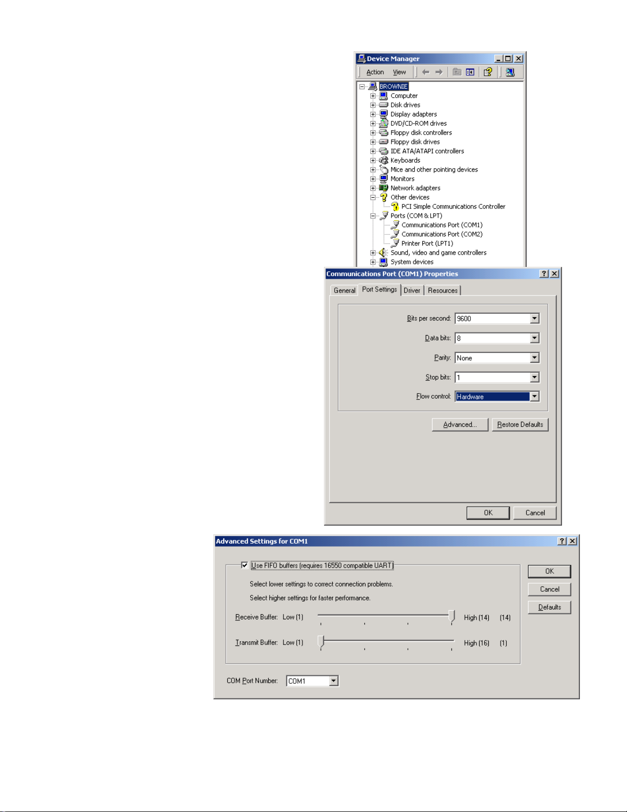
Click on the + in front of Ports (COM & LPT)
Right click on com port that is connected to cutter and
select properties
Select Port Settings page
Select bits per second = 9600
data bits = 8
Parity = none
stop bit 1
flow control hardware
Click on advanced
Check use FIFO buffers
Set Receive buffer = 14
Set Transmit buffer = 1
click on OK
click on OK
close device manage
(click on x in top right
corner)
click on OK
5

Setup for Windows 95/98
Right click on My Computer icon on
desktop and select properties. Select
Hardware page. Click on + in front of
Ports (COM & LPT). Click on Communication port connected to cutter.
Click on Properties button
Select Port Settings page
Select bits per second = 9600
data bits = 8
Parity = none
stop bit 1
flow control hardware
Click on advanced
UnCheck use FIFO buffers
click on OK
click on OK
click on OK
6 7

Loading Allen i-TECH Software
The Firmware Utility CD contains:
1. The Remote Panel Utility program for managing machine settings.
2. A current revision of firmware.
"Firmware" is software that controls the machine functions. The
firmware on this disk is provided for update purposes only and
should not be installed on new machines.
3. Manual and sample jobs.
4. Cutter driver for Window XP or Windows 2000.
The Remote Panel Utility Program
In order to easily control the many settings of the i-TECH CUTTER, it is necessary to install the
Remote Panel Utility Program.
If connected to a computer running under the Windows operating system, your Allen Datagraph
product has many settings for machine control that can be accessed by the Remote Panel Utility
program.
NOTE: Before running the setup program, be sure to exit the older version of the Remote Panel.
To install and run the Remote Panel Utility program - Open Windows Explorer by right clicking on
the Start Button. Find the CD-ROM drive and find the setup file Setupi-TECHBuildXX.zip (the
XX reflects the numeric version number of the software and firmware). Run the setup program by
double clicking on the file. Follow the onscreen prompts.
XP Installation Instructions
The downloaded file is a .zip file. You can run the setup program just by double clicking on the
*.zip file then double click on the setup *.exe file.
Other Windows Operating Systems Installations
If you have not already installed Winzip on your computer, download and install the Winzip program from
and drop the contents of the zip file to your desktop.
The setup program will run to install the Remote Panel and the firmware on your Windows computer. If instructed by the factory to upgrade your firmware, follow the firmware upgrade instructions below. If you were only instructed to upgrade to a new remote panel you have already completed this task and do not need to install the firmware.
http://www.winzip.com. Then you can open the zip file by double clicking on it. Drag
Installing Firmware
The firmware on this disk is provided for update purposes only and should not be installed on
new machines. In general you should not install a firmware update unless directed by a member
of the technical support staff. Firmware updates are available on the technical support page of
the Allen Datagraph web site at
This procedure details the firmware upgrade procedure. Normally firmware is only sent to customers when a software problem is reported that has been fixed in a later version of the software.
From time to time Allen Datagraph will recommend that you upgrade your firmware in your Allen
Datagraph i-TECH. A file can be downloaded from the Allen Datagraph web site and saved to the
desktop.
http://www.allendatagraph.com.
Before running the setup program be sure to exit the older version of the Remote Panel.
Firmware Installation Instructions:
Only install new firmware if instructed to do so by Allen Datagraph.

Refer to Title : Printer Conflict
Website Copy / CD Copy if you
have installed some other printer
driver other than the Allen Datagraph printer driver.
Turn on the Allen Datagraph
equipment to be upgraded and
connect it to your computer with
the supplied serial cable. Start
the Remote Panel by clicking on
start, program, Allen Datagraph,
Remote Panel. Click on Setup,
Com Port and verify that the correct Com port has a check next to
its name. Click on Setup -> Options and select Advanced on the menus. Click
on
Action, Upload Firmware. Select
I960a.hex file and click
fails, you will be given a backup procedure to
follow on the computer screen.
Open. If the upload
Windows XP / Windows 2000 Driver
This printer driver has been tested with CorelDRAW, Adobe Illustrator, Flexisign, and PowerCAD.
It should work with any program that sends vectors rather than bitmaps to the printer. Allows cutting directly from windows graphics programs without requiring additional software purchases.
Note: Driver requires ownership of Allen Datagraph Equipment to use. Requires: Windows XP or
Windows 2000. The setup program for the printer driver is available on the supplied CD or on the
tech support page at the Allen Datagraph web site at
http://www.allendatagraph.com/.
Installation instructions
Run Setup. The setup is named SetupCutterDriverxx.EXE on the supplied CD. A shortcut to the
installation instructions will be placed on the desktop. (DirectCut Help File). Documentation for
the printer driver is included in the help file.
8

Optional SmartMarkTM Sensor
The SmartMarkTM option that is available for Allen i-TECH cutters is an optical registration system
that allows cutting of pre-printed graphics. The SmatMark system has the capability of recognizing
up to three registration marks, and adjusting for scale and skew discrepancies the may occur.
TM
The SmartMark
tic transmit/receive leads that connect to the amplifier, a lens assembly that is attached to the tool
block assembly of the cutting head, and associated internal cutter wiring.
The SmartMarkTM sensor recognizes changes in contrast from the background media to the printed
mark. The “sensitivity” of the sensor must be set in order for the system to recognize the contrast
reliably and be able to cut accurately.
option consists of an amplifier that is mounted to the cutting head, two fiber op-
Registration Mark
MARK SIZE
LABEL
LIN E SIZE
Standard SmartMarkTM Registration Mark Origin Point
The recommended target is available for Adobe Illustrator and CorelDraw for download on the
technical support page of the Allen Datagraph web site (
designing a target for scanning, read the Title: Why thick lines don’t work
http://www.allendatagraph.com). When
Website Copy / CD
Copy. The recommended Mark Size is 0.5 inch (12.7mm) the size can be as small as 0.25 inch
(6.35 mm) or as large as 1 inch (25.4mm) The recommended line size is 0.13 (3.3mm) and can be
as small as 0.07 inch (1.8mm). The registration mark should be printed with as high a contrast as
possible. The sensor relies on reading the change in intensity of the reflection of the red LED
pointer. When printing process colors on white media the best color is usually black. Certain spot
colors are difficult. For example silver spot on white, while to the eye there is contrast the reflectivity of the two is sometimes nearly the same. Different medias also have different reflectivity and
will on occasion require adjusting the sensor sensitivity (see below). If there is trouble with certain
materials detecting the target you can print the target in a yellow or white field. The size of the
yellow field should be double the scan distance. (Note: in order to get an accurate scan no other
printed marks may appear in the yellow scan area. The printer color alignment marks can appear
on the inside edge of the target or the other side of the media.)
9

The mark should be placed at least 0.5 inches (12.7mm) from the edge of the media and the spacing between jobs should be at least 0.5 inch (12.7mm). (Advanced usage: You can place the target
closer to the edge of the material if the area of the platen that is scanned by the sensor is covered
with the same color material as the background material.)
The number of rows and columns of labels between registration marks defines a set or
page of labels. A page of labels can be one row or several
rows of labels. There are several aspects to consider when
deciding on how many rows of
labels to print on one page. The
main consideration is the trade
off between speed (it takes a
couple of seconds to perform
the FO command and scan the
registration mark) and registration accuracy. The more often
you scan the registration mark
(the closer the marks) the more
accurate the cut registration will
be. If the job allows for overprinting the cut line, then registration may be less critical and eliminating some of the registration marks can speed the job. Generally registration marks should be placed at least every 24 inches (610mm). Most users print registration marks for each row then adjust the cut job to skip one or more marks if desired. This procedure also insures equal spacing of the labels and gives complete flexibility for cutting. The distance between the last cut line of the previous page and the target on the next page must be between
0 and 1 inch (2.54 cm). If the distance between frames is less than the scan length, then the target
must be outside of the area where the labels are printed. (Note: every page of a label run must be
identical or you won’t be able to use the copy command).
ONE PAGE
Operation
The theory of operation relies on the sensor sending a signal to the i-TECH embedded computer
when the SmartMark™ senses a change in reflected light from the media as it would when the sensor scans the printed registration mark. The i-TECH scans the mark in both directions and registers
the intersection of the mark. The i-TECH computer then assigns that intersection as the 0,0 point
of the cutter coordinate system and matches that to the origin point of the HPGL cut file.
The i-TECH uses a special HPGL command, FO, to start the registration mark sensing function. It
can automatically re-register the coordinate each time the FO HPGL command is received. As part
of the setup a “x move between jobs” is input via the remote panel which moves the sensor to the
approximate position of the next copy’s or next job’s registration mark. The space between jobs in
the printer driver also affects the where the next target is located. These two parameters are added
together. The i-TECH expects the target for the next frame to be within ½ the scan distance of the
end of the job.
The Red LED pointer must be manually positioned with the joystick buttons at the approximate 0,0 coordinate position prior to
sending the first job. The SmartMark™ system automatically repositions the sensor for
subsequent copies.
10
(0,0 POINT)
LED POINTER

The positioning process must be repeated if the joystick buttons are used. This is helpful because it
allows the system to be reinitialized when needed. Some printers require a leader between jobs and
this feature is a very easy way to deal with the issue.
Once the LED pointer is positioned as shown, the SmartMark™ is ready to operate and will scan
the registration mark when it receives a FO command in the job stream whether on the first copy or
on subsequent copies. Since the FO command is embedded in the beginning of the cut file the scan
of the registration mark is performed at the beginning of each copy or set of labels and on subsequent copies.
SmartMark™ Setup
There are several adjustable parameters built in to the SmartMarkTM sensor that give the system its
extreme flexibility. Some of the parameters can be automatically set by the microprocessors embedded in the system and some require manual intervention.
Sensitivity
1. In order to accurately sense the registration mark the SmartMark™ System operates using very fast signals at fairly low signal levels. All systems operating in this manner
are subject to interference from outside electro magnetic sources. In order to limit the
effects of outside interference the SmartMark™ system uses a high logic signal when
the sensor is off the mark and a low logic signal when the sensor is on the mark. In
normal operation the sensor sends a high logic signal when the sensor is on a light
background and a low logic signal when on a dark registration mark (L on). The sensor allows for sensing light registration marks on dark backgrounds by changing its
state so that the sensor sends a high logic signal when on a dark background and a low
logic signal when on a light registration mark (D on). The (L / D On) operation is set
by pressing the mode key 3 times. The current setting will be displayed. If the jog
switch is moved, the opposite setting for the output operation will be displayed. If the
jog switch is pressed, the digital display will blink quickly 3 times and the selected
output operation will be confirmed. Press the “MODE” key 3 times or keep it pressed
for 2 seconds or more to return to “RUN” mode.
2. ective value passes the set threshold
The sensor changes its logic state when the refl
level. The sensor utilizes a self-teaching program to set this threshold level. There are
multiple methods for setting the threshold level. The preferred is the Two Level
11

X
Teaching Mode, which will allow you to set a middle ground threshold value. Select
the “TEACH” mode by pressing the Mode Key once. Press the jog switch when the red
dot is on the material background. The display will blink then the “TEACH” (yellow
light) will blink. This indicates that the second point is now ready for input. Move the
sensor over the registration mark and press the jog switch, again the display will blink.
The display will either indicate the word “GOOD” which indicates that stable sensing
can be performed or “HARD” indicating stable sensing cannot be performed. The
threshold value setting will be displayed then the display will blink with the characters
“——“. The incident light intensity will again be displayed, indicating that configuration is now complete. Press the “MODE” key 5 times or keep it pressed for 2 seconds
or more to return to “RUN” mode.
3. r should be: As the LED moves into the registra-
The performance you are looking fo
tion mark from the background area the Operation Indicator (orange light) will activate
(ON), and then deactivate (OFF) when moved back into the material background area,
all the while the green light (Stability Indicator) will remain lit. If you have the “Loff” selected on the operation selection, the operation of the orange Operation Indicator
will be opposite.
4. ation regarding advanced programming and operation of the sensor
Additional inform
can be found in Appendix D “SmartMark™ setup”.
Sensor Offsets
The SmartMark™ sensor is offset from t e. The red dot indicates the LED point
and the blue circle represent the knife. This value is normally setup at the factory or during installation of the i-TECH. The offset distance is preset at the factory, but may need to be adjusted on
occasion. You may follow this procedure only if you
own a digitizing site (Allen p/n PL-00-11-500). Otherwise you must follow the manual procedure described in the TSB Calibration
Copy .
he center of the knif
Website Copy / CD
Y OFFSET
OFFSET
12

To automatically reprogram the SmartMark™ sensor
offset and sensor size parameters: Open the i-TECH
Remote Panel. Open the
click on
SmartMarkTM Setup
Diagnostics Menu and
1. Before running this procedure run the Calibrate to Printer diagnostic.
2. Print the 6x3 rectangle in c:\Program Files\Allen Datagraph\Sample directory on the same
printer you ran the “calibrate to printer diagnostic”.
3. Enter the designed size of the rectangle in the Rectangle Size boxes
4. Load Media into cutter.
TM
5. Move the SmartMark
6. Click on Find Sensor Size and Offset. This determines the size of sensor based on the fo-
cal length and the current setting of the threshold.
7. After scanning the scale, skew, and origin points you will be asked to joystick the carriage
to the lower right corner of the rectangle. Use either the optional fiber optic bombsite so
that the center of the bombsite is directly above the lower right hand corner of the printed
rectangle.
8. Click on OK to save new values or Cancel to restore original values.
You can review the numbers by opening the
section describing the line sensor menu.
Sensor beam near the lower right corner of the 6x3 rectangle
Setup Menu, click on Line Sensor Menu. See
13
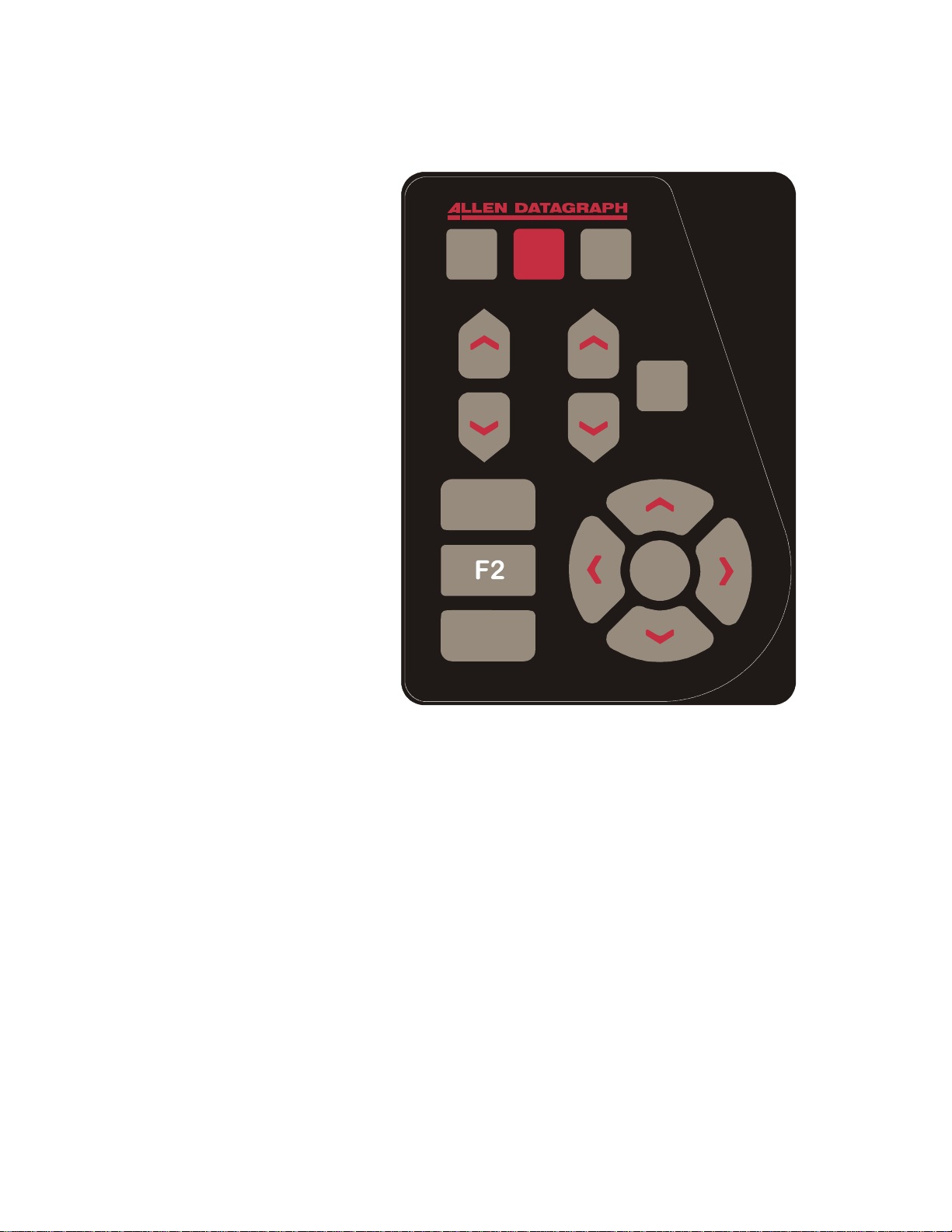
Control Panel
The front control panel is the primary user interface for the i-TECH cutter. It is used for input of
speed and force as well as several other functions.
LOAD The load key is used to ini-
tialize the system and to load or
automatically fill the supply dancer
bar. Once the material is fed thru
the media path and the nip rollers
are engaged (see media loading section), press the load key and the
supply roller will start feeding media into the supply dancer bar and
will automatically stop once the
supply dancer bar reaches the bottom and the loop is full. If the media height sensor is off, the load
light will then come on to indicate
the system is ready to operate. If
the media height sensor is turned o
the system will scan the digital die
cutter station pinch rollers to dete
mine the media width (see Label
Remote section). Be sure that the
label frame you want to cut is at
least 2 inches behind the knife blade
before pressing load.
n,
r-
L P
LOAD
PAUSE COPY
S
P
E
E
D
F1
F
O
R
C
E
C
TC
TEST
CUT
SELECT
PAUSE The pause key will halt the
operation of the system at any point.
It is used to pause the system for
inspection, media jams or to pause
the machine for any other reason.
Press the pause key to re-start the system. The system can be jogged while paused and will remember where it was and restart from where it was stopped regardless of where it was jogged.
This is very helpful for inspecting the cut. You can pause the system and joystick the media or cut
head away from its position to inspect the cutting or registration. After inspecting the media, simply press the pause key again and the i-TECH will return to the point where it was paused and resume cutting. The pause light will flash while the system is paused. You can also use the pause
button to enter the unload state (press Pause followed by Load).
F3
COPY The copy key is used to input the quantity of copies the i-TECH will digitally die cut. It is
used after the first copy of the job is cut. Once the first copy is cut and you are happy with the results, press the copy key. The display will read 0002. The number represents the total number
of copies including the first one run. Increase the number of copies by pressing the up arrow key
of the joystick or the force up button. Hold the key down and the numbers will start moving slowing then more quickly. Press the down arrow key to lower the number. Alternatively the force
keys will increment the single digits and the speed keys will increment the 10’s digits. Remember
the number displayed includes the first copy run before the copy key was pressed. Input the copy
quantity and start the cutting by pressing the
SELECT KEY.
SPEED The speed keys are used for controlling the cut speed (the speed the knife travels around
the periphery of the items being cut). Increase the speed by pressing the up arrow key. Decrease
the speed by pressing the down arrow key. Hold the key down and the numbers will start moving
14

slowing then more quickly. The i-TECH will also self adjust the speed within certain limits based
on the speed of the device feeding the unit. The range for speed is 1 to 100.
FORCE The force key is used in conjunction with the test cut key to set the depth of cut. The
factory default for cutting is set at 12. The range of force is 1 to 100 when the system is in the
normal force range and 1 to 1000 when in the 1000 step mode. For most applications the normal
force range is adequate (see dynamic force and 1000-step mode in the Remote Panel section). In
the normal force range mode, the force is adjustable between 10 and 550 grams of force in 100
steps.
The force is set by test cutting the media to be cut using the test cut function. Using the joystick, position the knife in an unused portion of the me-
dia and press the
similar to the diagram to the right. With a sharp knife or tweezers you
should be able to individually remove each part of the test cut pattern working from the ring to the triangle without affecting the remaining parts. A
properly set force will leave a very slight scratch or mark on the liner.
The force may need to be adjusted due to blade wear during use if problems with weeding occur.
Simply increase the force setting by one until satisfactory weeding occurs. If the knife blade is
changed, revert back to the original setting or perform the test cut procedure again. The blade may
need to be replaced if the force is increased by more than 20 percent from when the blade was new.
TEST CUT key. The system will cut a test cut pattern
F1 This key puts the pen up or down during digitizing mode.
F2 This key is not used and has no function
F3 This key is a short cut to the OPER mode. It is equivalent to pressing select, left/right until
OPEr is displayed and pressing select.
RESET the cutter by pressing the F1, F2 and F3 keys in order.
JOYSTICK The joystick is used for positioning the knife
and media in the die cutting station and for several other functions.
The four
cutter carriage that holds the knife blade and the SmartMark™
sensor. Press the key once to move the material or carriage
slowly and press it a second time within ½ second to move at
a faster speed. Tap the key to jog the cutter a fixed distance.
The distance is adjustable (see Joy section below or joystick in
the Remote Panel section).
SELECT
will change to indicate the last used menu item. To select a menu item press the select key and
then press the right or left arrow key to scroll thru the various menu items. With the desired menu
item displayed, press the up or down arrow key to select the state. When the desired state is displayed press the select key to input the menu item and state. The menu items are: ACCL, CAd,
diA, indE, JOY, OPEr, and Set.
ARROW KEYS are used to jog the material or
SELECT
The select key is used to invoke the menu system. Press the select key and the display
Menu Items:
ACCL allows setting the acceleration in ¼ G increments. Acceleration is the rate of in-
crease/decrease of speed of the motors along a vector. Higher G values increase throughput however higher G values also increase the likelihood of experiencing repeatability problems. Recommended values are (2-8) for standard labels.
15 16

CAd override menu function enables or disables the CAD override function. With the function
On the cutter will ignore some HPGL control commands sent from the cutting software. With the
function Off the CAD software can control these HPGL commands.
The commands affected by CAd override are:
AS set acceleration
FS set force
KA set minimum a ngle
KN set knife offset
IP input P1/P2
RO rotate
SC set scale
SP select pen
ST select tool
UV up velocity (move speed)
VS down velocity (cut speed)
Press the select key to initiate the menu function. Press the left or right arrow key to display CAd,
then press the up or down key to toggle between off and on. Press the select key to lock in the
desired menu setting.
diA is used for entering into the diagnostic mode. Press the select key to initiate the menu func-
tion, then press the left or right arrow key to display diA. Press the up or down key to scroll thru
the diagnostic numbers (0002 – 0099). Press the select key to start the diagnostic. (see diagnostics
section) . To exit from a diagnostic mode select 0099 and press select.
IndE indexes the x-axis. One of the uses for this function is for metering material. Press the se-
lect key to initiate the menu function, then press the left or right arrow key to display IndE.
Press the select key. Press the up or down arrow to toggle between inches (InCH) or centimeters
(cEnt). When the desired unit of measure is displayed press the select key. The display will read
0001. The number represents the number of inches or centimeters to be metered in the x-axis.
Increase the number by pressing the up arrow key of the joystick. Hold the key down and the
numbers will start moving slowing then more quickly. Press the down arrow key to lower the
number. Alternatively the force keys will increment the single digits and the speed keys will increment the 10’s digits. Input the length and start by pressing the select key.
JOy allows changing the joystick parameters: of jog distance or slew speed. Press the select key
to enter the menu system. Press the left or right joystick buttons until JOy is displayed. Press up
or down on the joystick to select (Sped or Jog). Press select. Press up or down on the joystick to
select a value for joystick speed (1-100%) or jog distance (0.01 inch increments). Press select to
save the displayed value.
This menu item has 2 sub-menus:
Sped- Allows the user to set the maximum speed that the joystick will move the material
or head when pressed twice. Range 1-60.
Jog- Allows the user to set the distance that the head or material will move when a joystick
button is pressed and released. Range is 1-100 in 1/1000
100=.100”
th
inch increments. i.e., 1=.001”,
OPEr is used to select the operation mode between cutting (CUt), pen plotting/drawing (drA) or
pouncing (POUn). Press the select key to initiate the menu function, then press the left or right arrow key to display OPEr. Press the up or down key to select the desired function. Press the select
key to lock the desired menu setting.
SEt loads or saves a custom set-up or power up default. Press the select key to initiate the menu
function. Press the left or right arrow key to display SEt. Press the up or down key to scroll thru

(LOAd, Save), press select, press the up or down key to scroll thru the settings (1 – 6). Press the
select key to load or are save the setting. Setting #1 is loaded when the machine is powered up.
(see also factory and custom set-up section)
The set menu item has 2 sub-menus:
Load- loads a setup.
To load a setting:
Press select
Press left or right arrow until SET menu is displayed.
Press up or down arrow to display Load.
Press select
Press up or down arrow to display the number of the setting you want to
load (1-6)
Press select.
Save- saves a customized setting.
To save a setting:
Adjust force, speed, acceleration as needed.
Press select
Press left or right arrow until SET menu is displayed.
Press up or down arrow to display Save.
Press select
Press up or down arrow to display the number of the setting you want to
customize (1-6) (# 1 is the setting that is loaded on power up.)
Press select.
The display will blink FFFF, and then return back to your setting.
17
Remote Panel
The Remote Panel program is used to address all i-TECH CUTTER functions. It should be loaded
onto the computer that is directly connected to the i-TECH CUTTER. We recommend that you
place a shortcut on the Windows Desktop so that you can easily start the program when needed. It
can be run in the background with most cad programs.
If running a design program that utilizes a compliant windows printer driver or when using the Allen Datagraph Windows XP / 2000
driver, be aware that all windows
printer drivers can grab hold of the
COM port and keep programs that
talk directly to com port from
working. Symptoms: E56, funny
characters on LCD display, plots
not finishing, slow send. To
eliminate the problem read the
Title Communication Failure
Website Copy / CD Copy
Remote Panel Functions
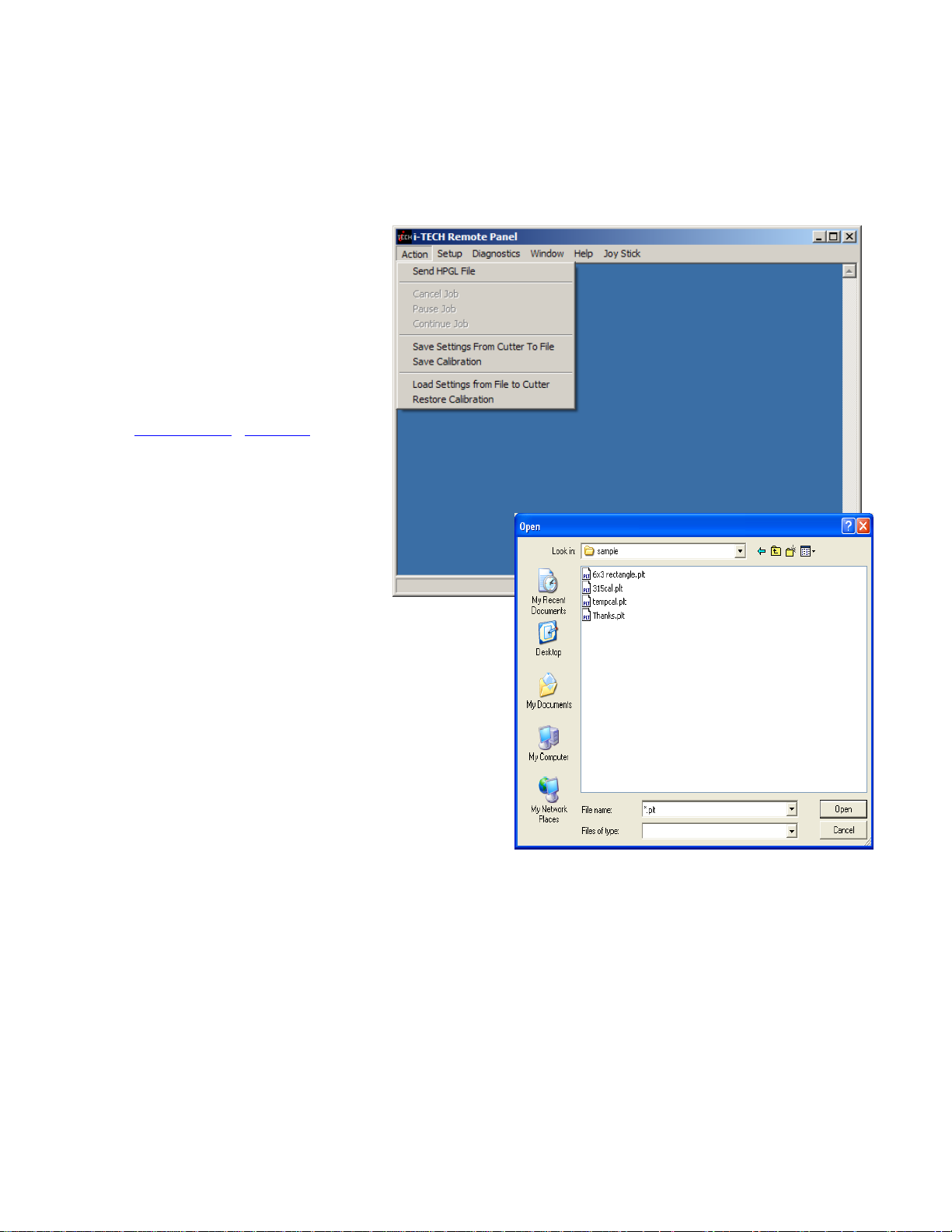
Action menu
Send HPGL File
Send HPGL File will send a HPGL
plotter file directly to the Cutter.
Typical origins HPGL files include the Allen Driver,
CorelDraw or some other design software. To send a
HPGL plotter file from the remote panel program
click the Send HPGL File menu item to open the select file window. Select the files desired and click
the Open button. This will send the file directly to
the Cutter.
Cancel, Continue, Pause
These commands will cancel, continue, or pause a
job being sent by the Send HPGL command. For
jobs sent by other programs you can use the Pause
button on the cutter and the (F1, F2, F3) combo to
cancel the currently cutting job.
Save Settings from Cutter to File, Load Settings from File To Cutter
These commands save the settings (see setup settings menu) and some line sensor parameters that
are in the i-TECH to a disk file or loads settings saved by this command from a file and sends them
to the i-TECH. This allows you to have more than 6 setups for different materials and it allows
backing up your settings to your hard drive in case of failure of the CPU board.
Save Calibration/Restore Calibration
This command saves line sensor parameters that depend on the calibration and calibration of the
cutter or allows loading the calibration parameters from a file. This command allows calibration of
the i-TECH to multiple printers.
18

Advanced menu items (These menu items appear if you select the advanced menu
on the Setup Option menu)
Open Com Port
Will initialize the communications port.
Close Com Port
Closes the communications port so that other programs can use the port. The remote panel program will automatically close the port in most instances when it is not actively communicating with
the i-TECH.
Upload Firmware
Should your firmware ever need to be updated, this command will locate the firmware file and send
it to the i-TECH.
Save to EEROM and Restore from EEROM
These commands are used to save custom settings and factory settings to the computer when certain electronic components need to be replaced.
Setup Menu
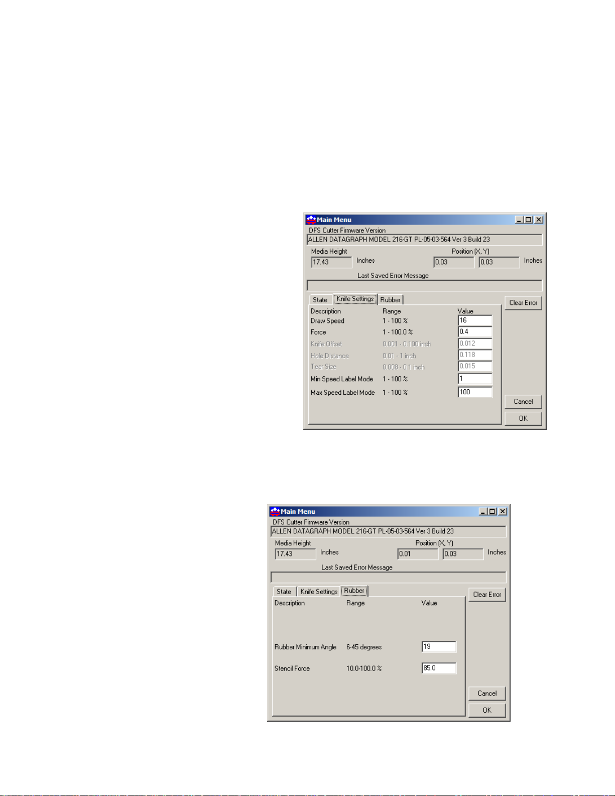
Main Menu
The Main menu opens the main menu window. The top window shows the model number and
firmware version (build 23 in the sample). The media height window shows the maximum dimension the i-TECH is set to cut. With the media height sensors enabled, the i-TECH will scan the
pinch wheel magnets to determine the loaded media size and will calculate the maximum cut size.
The i-TECH will send this dimension (called the clip limits) to many software programs so that the
software program can determine if the specified cut file will fit. If a file with dimensions larger
than the clip limit is sent to the i-TECH, the cut will be truncated. If the media height sensor is
disabled, the default clip limits will be used and it is possible to cut off the edge of the media. The
position window shows the current location of the knife in the cutter coordinate system. The Last
Saved Error Message window displays the last error. Errors displayed here may be old. The error
may have occurred earlier in the cutters life. The
saved error notification.
Clear Error button clears the memory of the
State Tab
The
State radio buttons allow the user to set the condition of the cutter. Unload means the cutter
is not loaded and is not ready to receive a cut file. The Pause radio button means the cutter is currently paused and the Ready button means the cutter is loaded and ready to receive the cut file and
proceed with cutting. This set of buttons duplicates the Load and Pause buttons on the front panel.
The CAd Override radio buttons enables or disables the CAD override function. With the
function
software. With the function
tems will work correctly only when this feature is set to on.
These commands include:
AS set acceleration
FS set force
KA set minimum a ngle
KN set knife offset
IP input P1/P2
RO rotate
SC set scale
SP select pen
On, the cutter will ignore some of the HPGL control commands sent from the cutting
Off, the software can control these HPGL functions. Some CAD sys-
19
ST select tool
UV up velocity (move speed)
VS down velocity (cut speed)
The Mode radio butons sets the operation. Select cutting, pen plotting/drawing or pouncing.
The i-TECH will normally only use the Cut function.
The Dynamic Force radio buttons (an advanced option) engages the dynamic force function,
which instantaneously adjusts the force on the fly based on the actual velocity of the knife blade.
All cutters must accelerate and decelerate as they cut around corners. Some medias require different force settings for different speeds. This parameter allows for building a database for these materials and when enabled will greatly improve the cutting on these materials. (See the Dynamic
Force Section for more details).
Knife Settings Tab
Draw Speed displays and sets the velocity
of the knife when it is actually drawing or
cutting. The draw speed is the speed the knife
travels around the periphery of the items being
cut. The i-TECH will also self adjust the
speed within certain limits based on the speed
of the device feeding the unit. The range for
speed is 1 to 100%.
Force displays and sets the cutting force.
The default force for cutting is set at 12. The
range of force is 1 to 100%.
Knife Offset is the distance between the
center of the knife blade and the knife tip.
Standard blades have a 0.012 inch (.030 cm)
offset. If you have objects that do not close
correctly, you might have to adjust the knife offset to correct the problem.
Hole Distance and Tear Size are used when the cutter is in the Pounce Mode. The hole dis-
tance setting is the distance between holes and the tear size is the distance the cutter moves with the
pounce tool down to tear the media and enlarge the pounced hole.
Min Speed Label Mode and Max
Speed Label Mode
the limits for the automatic speed
setting function of the i-TECH. The
cutting speed will automatically
increase or decrease, within the limits
set here, to keep pace with the in feed
device. Normally you set the Max to
100 and the min to 1.
are used to set
Rubber Tab
Rubber Minimum Angle displays
and sets the angle between consecutive vectors that when exceeded will
invoke the tangential emulation mode.
At angles less than the value set in
this parameter the cutter will move
between vectors without evoking the tangential emulation mode.
20
Stencil Force is the force separation between drag knife mode and tangential emulation cut
mode. Tangential emulation cut mode is normally used for rubber or very heavy material.
Advanced menu items (These menu items appear if you select the advanced menu
on the Setup Option menu)
Rubber Scratch Force displays and sets the down force used during tangential emulation.
This is primarily used when cutting thick materials such as sandblast rubber. Tangential emulation
simulates a tangential or servo controlled rotating knife by moving to a position short of the vector
to be cut and putting the knife blade down with a very light force while moving toward the direction of cut to align the knife before applying the full cutting force. This improves the cut quality in
thick materials. (default 0.1%)
Rubber Backup Multiplier (default 20) displays and sets the distance the knife will be dragged
at the light force used to align it. This parameter is used with and is additive to the
Backup Offset
between vectors and the Rubber Backup Offset is a constant added to the distance calculated based
on angle.
(default 0.02). The Rubber Backup Multiplier is based on the change of angle
Rubber
Rubber Minimum Angle (default 19) is the rotation angle between two vectors that enables
tangential emulation. Subsequent vectors that have angle between them exceeding this parameter
cause the pen to be picked up, dragged along the surface to align the knife and plunged into the
media at the beginning of the next vector. Subsequent vectors that have angle between them less
than this parameter will perform a drag rotation.
Max Motion Vector Length (default 0.001) (Named after the driver that outputs very small
vectors) Allen Cutters very accurately replicate the vectors in the HPGL plot file. Some design
programs output vectors that are very short. It is sometimes desirable to combine some of these
vectors into a longer vector to eliminate jagged edges or slow cutting. This parameter works like a
curve-smoothing algorithm and is used to improve poor HPGL files.
Anticipation Rubber (default 0.002) and Anticipation Vinyl (default 0.0004) is a parame-
ter that adjusts the backlash compensation in the cutter. The Anticipation Rubber is the parameter
used when the cutter is in tangential emulation mode and the Anticipation Vinyl is the parameter
used when not in tangential emulation
mode. Heavier materials require more
backlash compensation. These numbers
are individually set at the factory and
should not require adjustment except
when cutting heavy materials. If you are
experiencing thick and thin lines or
misshaped letters, adjust the anticipation
parameter to obtain satisfactory results.
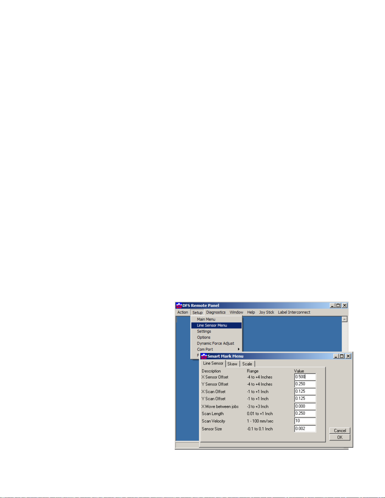
Line Sensor
Clicking on Setup Line Sensor menu
opens the SmartMark
Line Sensor Tab
TM
Menu.
Sensor Offsets - The SmartMark™
sensor is offset from the center of the
knife. The offset distance is preset at the
factory or during installation, but may
need to be adjusted on occasion. The i-
21

TECH will automatically calculate and set the SmartMark™ offset and sensor size parameters. See
drawing for definition of sensor offsets. Title: Calibration
Website Copy / CD Copy.
Sensor size is the offset from the exact
center of the red dot of the SmartMark™
sensor to the sense radius and may
change based on sensor sensitivity or
media reflectivity. This parameter is best
set using the procedure in the TSB. The
Sensor Size parameter is only useful in
three target scanning. If you are not
using three-target scanning you can set
the size to 0 and the sensor size is included in the sensor-offset parameter.
Scanning Parameters
The i-TECH SmartMark™ system has adjustable scanning
parameters to allow for different size and style of registration
marks. The primary parameters are the scan offset and
length. The ideal X and Y offsets are one-half the mark size
and the ideal scan length is two
times the scan offset.
To set the parameters type in the desired numbers in the
Offset, Y Scan Offset
entered the desired values click on
and Scan Length.When you have
LABEL
OK. (see also registration mark section)
MARK SIZE
LIN E SIZE
X Scan
X OFFSET
`
Y OFFSET
SCAN LENGTH
Scan Velocity (default 10) sets the speed of the scanning. Depending on the media and registra-
tion mark contrast, this parameter may need to be adjusted. The better the contrast in reflectivity
the faster the scan velocity can be set. If you are experiencing missed registration marks, you may
need to reduce the scan velocity.
X move between jobs is the distance after the farthest excursion of the x-axis during a frame
that the i-TECH should advance to find the target in the next frame of labels. This item is duplicated in the DirectCut printer driver as the space between jobs. These two parameters are added
together so if the printer driver is normally used, the parameter is set to 0. Since the two parameters
are added together you can also use this parameter to allow cutting labels whose distance between
frames is between 1 and 2 inches.
Advanced menu item (This menu item appears if you select the advanced menu on
the Setup Option menu)
Target Scan Direction sets the direction of the scanning operation. For single mark origin
scanning the default target scan direction is
be desirable to reverse the scan direction. For instance, the mark might be printed to close to the
trailing edge of the preceding labels limiting the distance available for scanning. In this instance, it
might be desirable to reverse the scan direction in the X-axis. Consideration must be given in the
+X, +Y. There may be circumstances where it might
22

cut file because the inside edge of the mark will be considered as the 0,0 point for the cutter coordinate system.
Skew Tab
The SmartMark™ system can use one, two
or three registration marks. In standard
operation the i-TECH only requires one
registration mark to accurately cut the die
lines of most labels. If, however, there is a
problem with the printing it may become
desirable to use multiple registration
marks. (see also discussion about marks in
Tutorial Using Adobe Illustrator section)
When using two registration marks the
embedded computer in the i-TECH will
automatically scan both the Origin Point and the
Skew Point. This is helpful if the printing is skewed
in relationship to the media.
When using multiple registration points it is helpful
to understand the FO command and its parameters.
Note: scaling without skew is not implemented.
X, Y Scan offset. This is the distance from the
skew point to perform the Y and X scans to find the
skew point. With the targets defined as above, the X, +Y is the correct signs for the scan offset for the
skew mark.
Scan Skew Point - A fourth scanning mode is
implemented that performs scaling and skewing by scanning only two marks (origin and scale).
This method assumes there is no scaling error in the Y-axis. (Specify the Origin, Skew, and Scale
mode in the printer driver). By checking the scan skew mark off, the i-TECH will only scan the
Scale and Skew mark and perform X-axis scaling and skew correction.
Advanced menu items (These menu items appear if you select the advanced menu
on the Setup Option menu)
Y Target Location. This is the distance between the origin target and the skew target when the
nd
2
parameter of the FO command is –1. This command is used on CAD systems that do not emit
the FO HPGL command. You set up the initialization string to have
BJ1;FO-1,-1; <for origin skew and scale processing>
or
BJ1;FO0,-1; <for origin and skew processing>
This causes the cutter to look at the Y Target Location parameter from this menu item.
Target Scan Direction sets the direction of the scanning operation. The skew mark is normally
scanned
document.
+X,-Y. Changing the direction of the skew scan direction is beyond the scope of this
23

Scale Tab
X, Y Scan Offset. This is the distance
from the scale point to perform the Y and
X scans to find the scale point. With the
targets defined as above, the -X, +Y are
the correct signs of scan offset for the
scale target.
Advanced menu items (These
menu items appear if you select
the advanced menu on the Setup
Option menu)
X Target Location. This is the distance between the origin target and the scale target when the
st
1
parameter of the FO command is –1. This command is used on CAD systems that do not emit
the FO hpgl command. You set up the initialization string to have:
BJ1;FO-1,-1; <for origin skew and scale processing>
This causes the cutter to look at the X target location parameter from this menu item.
Target Scan Direction sets the direction of the scanning operation. The scale mark is normally
scanned
tion. Changing the scale
scan direction is beyond the
scope of this document.
-X,+Y. There may be circumstances where it might be desirable to reverse the scan direc-
Settings Menu
The i-TECH allows six factory or custom set-ups.
Set-Up 1, whether standard
or modified, is automatically
loaded at power up. A user
may modify the speed,
force, (or any feature) on the
control panel. See key
command summary.
Changes to a Set-Up, unless
saved, will be in effect only
until changed from the control panel, CAS software, the unit is
turned off or reloaded.
Any of the features shown in the Setup
Form may be saved to one of the systems 6 memory locations.
To save a custom set-up simply fill in the desired value(s) in the appropriate window, including the
Setup Number, click on the
To load the edit boxes with the current system parameters, input the setup number in the
Save Setup button.
Setup
Number window and then click the Load Setup button.
Setup Number sets the memory position.
Draw Speed is the velocity of the knife when cutting (e.g. while the knife is down).
24

Move Speed is the velocity of the knife when in the up position (not cutting).
Force controls the down force or pressure on the knife.
Knife Offset
with the tip offset from the center of rotation. As the
cutter moves the knife trails behind it, just like a caster
on an office chair. In order to accurately cut the outlines, the computer embedded in the cutter
compensates for the offset of the knife. This parameter sets the offset for those calculations. The figure to
the right shows the path the knife follows; the radius
move at the corner allows for the knife offset. The standard blade (Allen P/N H20-007) available
at our online store at
cm).
All drag knife cutters use a knife blade
http://www.allendatagraph.com has a knife offset of (0.012 inch or 0.0304
CUTTER PATH
Minimum Angle The cutter must stop and then accelerate whenever it makes a sharp turn. At
shallow angles the cutter can continue at the cut velocity without decelerating then accelerating.
This parameter sets the angle where below which the cutter can continue without stopping. High
values increase throughput and lower value increase quality. Good quality can be obtained at reasonable speed at the default value of 12°.
Hole Distance displays and sets the distance between holes when the cutter is used in the pounce
mode.
Tear Size displays and sets the hole size created when the cutter is in the pounce mode.
Acceleration displays and sets the servo acceleration. The unit of measurement is 1/4 g’s or 8
feet per second. This parameter is more important in small graphics than in large labels or text. A
setting of 2 to 8 is generally the best for most label cutting. This parameter does affect throughput
speed on graphics with short vectors. As the graphics get larger the effect of higher acceleration
diminishes. Higher acceleration can degrade cut quality.
Load Speed displays and sets the speed of the material loading and the speed of the material pull
off in the service loop mode.
Load Length displays and sets the length of the material that is pulled during the load cycle and
service loop if the cutter service loop mode is on. This should be turned off on the i-TECH when
the cutter is in the Label Mode.
Dynamic Force (an advanced feature) engages the dynamic force function that instantaneously
adjusts the force on the fly based on the actual velocity of the knife blade. All cutters must accelerate and decelerate as they cut around corners. Some medias require different force settings for
different speeds. This parameter allows for building a database for these materials and when enabled will greatly improve the cutting on these materials. (See the Dynamic Force Section for more
details)
CAd Override On or OFF enables or disables the CAD function. With the function On (dis-
, the cutter will ignore some of the HPGL control commands sent from the cutting software.
abled)
With the function
These commands include:
AS set acceleration
FS set force
KA set minimum angle
KN set knife offset
Off, the software can control these HPGL functions.
25

IP input P1/P2
RO rotate
SC set scale
SP select pen
ST select tool
UV up velocity (move speed)
VS down velocity (cut speed)
Mode sets the operation mode. Select the operation mode cutting, pen plotting/drawing or pounc-
ing.
Coordinate System Allen Sys-
tems have four origins to allow for
flexibility when using various
CAD/CAS systems. The i-TECH is
shipped with the Long X coordinate
system in all factory set-ups and is
compatible with most plotter or printer
drivers. The choice of coordinate systems other than Long X is beyond the
scope of this document.
To restore the factory default to all
setups click the
Restore Default
button.
LOWER LEFT ORI GIN
(LONG Y)
+Y
A a
0,0
TOOL
+X
LOWER RIGHT ORIGIN
(LONG X)
+Y
TOOL
+X
A a
0,0
CENTER ORIGIN
TOOL
A a
-Y
+X
CENTER, ROTATED 180
-X
0,0
+Y
-X
+Y
0,0
+X
DFS COORDINATE SYSTEMS
-Y
A a
TOOL
26

Options Menu
The options menu displays and sets
the following parameters:
Auto Origin Offset determines
whether moving the joystick automatically sets the origin to (0,0).
Most CAD systems and the Allen
DirectCut printer driver require this
option to be set On. Set to Off when
cutting from a CAD system that
does not use the SmartMark™ sensor
such as the Gerber Omega software.
Language determines which lan-
guage the cutter uses. Select Hpgl
for most cad systems and the
DirectCUT
are using Gerber Omega select
Gerber. If your cad system only
output dmpl you can select this language.
TM
Printer Driver. If you
Media Height Sensor turns on or off the load function that senses the width of the media based
on the set up of the pinch wheels. With this function enabled, the cutter head will scan a magnet on
the pinch wheels to establish the height of the media. With the function off, the cutter is loaded
with the maximum width. This option is normally set to Off for label cutting.
Units sets the units of measure to English or Metric units.
Model sets the model number.
Menus option offers the more
advanced features of the
software. It is recommended
this be set to Normal until a
more advance feature is
understood or is required by
your operation. The menu
items below are displayed when
the menus is set to Advanced.
Autocad OH Command
determines how the system will
respond to the HPGL OH
command.
Expand Mode allows the cutter to cut past the normal clip limits in the Y-axis. This function
allows cutting and extra 1/2 inch wide.
High Resolution Force sets the force resolution to 1 to 1000 steps instead of 1 to 100 steps. It
is useful when cutting very hard to cut medias. It allow setting the force between two of the standard force settings. A force of 112 is equivalent to 11.2 % force. (also see the Dynamic Force Section)
Joystick Knife Offset this option controls whether the cutting data point includes or excludes
the knife offset. The normal setting is include. Exclude is used for CadLink’s SignCad program
27
when digitizing only. The SmartMark™ system ignores this setting and properly calculates the location regardless of the setting.
Language sets the computer to either the HPGL (normal) or DMPL language for the plot file.
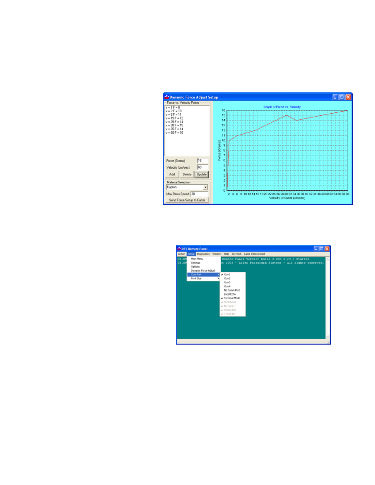
Dynamic Force Adjust
This feature is considered an advanced feature and does not appear on the Setup menu unless the
menu is set to advanced on the option page. Dynamic Force Adjust sets up the dynamic force parameters and database. To establish a
new material database type in the
name of the new material in the
terial Selection
box and click
Ma-
Add. In the Force and Velocity Win-
dow, type in the desired force vs. velocity that you have established for the
material. The recommended method
for establishing the various force vs.
velocity numbers is to run the test cut
at various velocities and record the
results for entry here.
Enter the Maximum cut speed for the
media in the
window.
Max Draw Speed
Before using Dynamic Force Adjust, it is necessary to send the force setup to the cutter memory by
clicking the
loaded or reset.
Send Force to Cutter button. This needs to be done after each time the cutter is
Com Port menu is used to set the com-
munications port to the Remote Panel only.
It does not set the communications port for
the design software or Allen Windows
Driver. The
communicating directly from the remote
panel while in
Local Echo mode is used in
Terminal Mode.
Font Size sets the font size for the Re-
mote Panel Program.
28
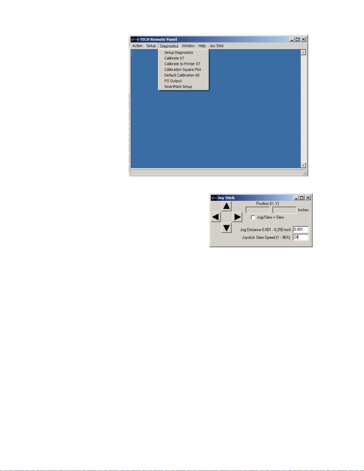
Diagnostics
See the diagnostics section
of this manual. Additional
diagnostics are available if
advanced menus are used.
Joy Stick
JOYSTICK The joystick is used for positioning the
knife and media in the die cutting station.
The four
or cutter carriage that holds the knife blade and the
SmartMark™ sensor. With the Jog/Slew box unchecked
so that Jog/Slew = Slew, the joystick speed will be the
speed set in the Joystick Speed Window. Left Click and hold the arrow button to move the material or carriage. With the Jog/Slew box checked so that Jog/Slew = Jog, the arrow buttons will jog
the cutter that fixed distance each time the button is clicked.
The setting in the Jog Distance Window also sets the jog distance for the Front Panel Joystick buttons.
ARROW KEYS are used to jog the material
i-TECH Cutter Loading Instructions
1. Power on i-TECH CUTTER unit. Allow system to initialize.
2. Insert media from the back of the cutter, passing the media over the lower roller that
has the large black disks, and under the upper roller that has the black rubber o-rings.
3. Pass the media under the pinch wheels.
4. Pass the media through the front rollers in the same fashion as you did in the
rear.
5. Align the right side of the media to the large black disks (front and rear tracking
guides). NOTE:These guides are factory set to be square with the grit wheel, and
should not be relocated unless directed to do so by Allen Datagraph.
6. Using 2 fingers, slide left side tracking guides to within 1/16” of material edge. These
guides have a tension spring in them, which can be adjusted with the 1/8” Allen
wrench supplied in your accessory kit. They should have enough tension to stay in
place during operation, but not so much that they can’t be moved by placing a finger
on each side of the roller and pushing toward the material.
29

7. Manually spool off some material from the roll into the rear media basket. Using the
joystick buttons, move the material forward and back to be sure that proper tracking
can be achieved. Raise the pinch wheels and make any material adjustments necessary.
8. Once proper tracking is achieved, retract the material to the first tracking guide and
press the LOAD button.
SEE APPENDIX C FOR LOADING DIAGRAMS
Installing Knife Blades
Summary
1. Insure plastic groove filler is in.
2. Install knife blade in knife holder.
3. Insure blade is out from depth guide.
4. Load material.
5. Install knife assembly.
6. Set machine to C
7. Perform cut test pattern.
8. Adjust force, offset and depth guide.
CAUTION: To avoid personal injury, keep hands, hair, clothing and jewelry away from
the cutter's moving parts at all times.
UT MODE.
Installing replacement blades
The knife blade should be replaced when the force has been increased by more than 20 percent or
the cut quality has degraded. The first sign of blade degradation usually occurs in the corners of
the cut and may lead to poor weeding.
New blades slide into the holder to a preset height and are held in magnetically. No tools or adjustments are required. To replace the blade, first remove the blade holder from the tool holder by
loosening the brass thumbscrew and pulling up on the silver knife holder. To remove the used
blade, grasp it with a pair of tweezers and pull it out of the knife holder (discard the blade safely).
Remove the new blade from the plastic case and remove the protective cap. Insert the blade into
the holder and let the magnet pull it into the preset position. Reinsert the knife holder into the tool
holder and tighten the brass thumbscrew.
Replacement blades are available from several sources including from Allen Datagraph Systems,
Inc. They can be purchased online @
(Allen P/N H20-007 45° for vinyl, H20-008 60° for thick materials and heavy laminates)
http://www.allendatagraph.com/ or by calling 603-893-1983.
Tool Holder Block
The knife blade holder is installed in the tool holder block with a thumbscrew. The tool holder
block is held to the cutting head by two hex drive screws.
Knife blade holder Assembly
The blade holder is designed for use with Allen Datagraph’s 45 and 60-degree blades. Solvents and
lubricants should
not be used, as they will diminish cutting accuracy.
30

Knife Blades
Knifes blades for the Allen Datagraph i-TECH Unit are made with tungsten carbide and are designed specifically for digital die cutting. The tip is offset from the center of the shaft so that the
blade has a caster action when pulled. Blades are available in 45 and 60-degree tip angles. The 60degree is intended only for thick materials such as sandblast mask or thick over-laminates. For best
cutting results, protect the knife tip from damage when not in use.
Knife Blades Depth Guide
Allen Datagraph's controlled depth knife holder has a depth guide that is adjustable to control the
depth of cut the cutter makes. Correct adjustments allow the blade to cut the material and lightly
mark the backer (carrier) material. Too much cut depth can cause cut through and premature blade
wear. Not enough cut depth will make "weeding" of media difficult.
Use the cut test, force and depth adjustment to establish good cutting (see setting cut force – cut
depth section)
Use the cut test and force to establish good cutting (see setting cut force – cut depth section)
Groove Filler
Clean any debris from the groove before installing a new groove filler. The filler simply snaps into
and out of place with no special tools required. It is important that the groove filler be installed
fully and evenly, otherwise material cut through may occur in some sections across the plotter. The groove filler should be installed for knives and pen plotting, but must be removed for
Pouncing
Tutorial Using Adobe Illustrator and SmartMark
Several additional documents have been written for using the printer driver with various CAD programs. They are on the tech support page of the Allen Datagraph web site.
http://www.allendatagraph.com.
TM
The most common CAD program used by our customers for label design and cut line preparation is
Adobe Illustrator 10. Other programs can be used as well as long as they send vectors rather than
raster images to the printer driver. Allen Datagraph has implemented the Allen Print utility for
Adobe Illustrator. You can download a sample label from the Allen Datagraph web site. The file
Website Copy / CD Copy contains several examples of labels and targets for Adobe Illustrator and
Corel Draw. Opening the file 3x5LabelForDFS2up.ai with Adobe Illustrator we see the following
screen.
31
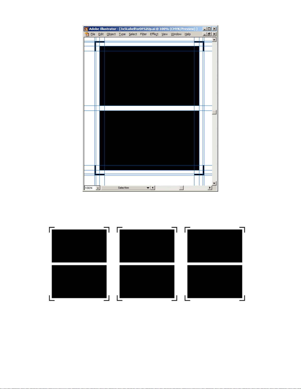
This file can be printed to your graphics printer. There are 2 labels and 4 targets. The file is completely symmetrical so it does not matter which way you print the labels. To test the setup, print
about 20 copies of the pair of labels. Print the labels with a 0.5-inch gutter between the labels.
After printing your printed media should look as follows:
Connect the power cord and the communications cable as described earlier in the document. Turn
on the power and/or emergency stop switch. Load the media as described in i-TECH Loading instructions.
Press the Load button on the remote panel. The i-TECH should fill up the front service loop and
turn on the Load LED on the front panel. Move the Red laser pointer near the gear side target (outside edge).
32
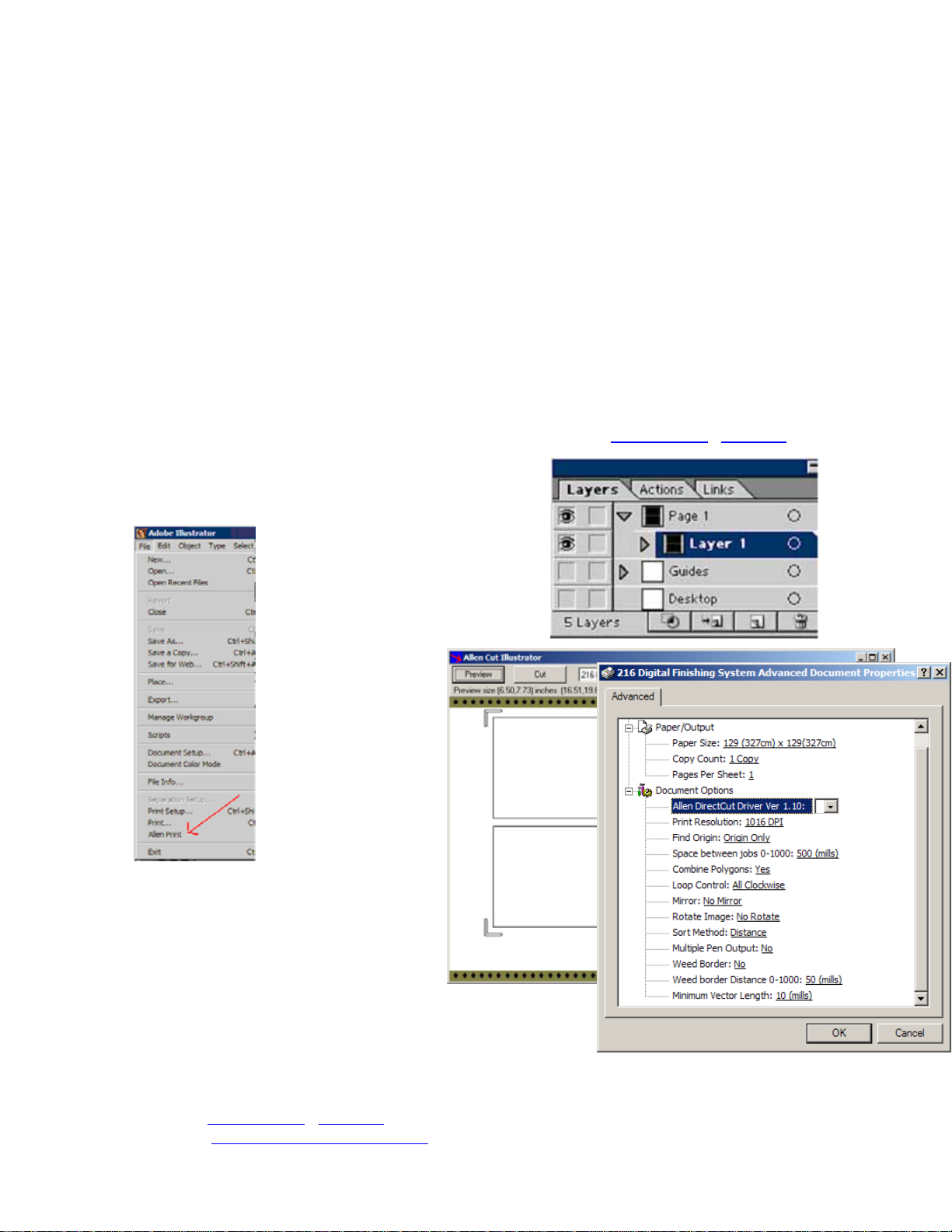
You now have to decide whether you will use scan one target, two targets or three targets to cut
your labels. One target can track drift of media (right/left/front/back). It does not correct for skew
(rotation) or scale (differences in the dimensions of the printed label and the cut image). One target
should be sufficient for most label jobs as the amount of area surrounding a label is somewhat
flexible.
Two target scanning while this mode has to scan two targets rather than one, it corrects for rotation in the printed image. This mode gives more accurate results than one target scanning. You
should use this mode when you have to maintain a very accurate narrow border. (E.g. You are cutting around a printed star and you want exactly 0.06 inch white border around the image.) With
this type of white border even small errors in cut line location are visible to the naked eye. As this
type of label requires more care and accuracy you should charge more for them.
Three target scanning is normally only required when you have multiple printers that do not scale
images exactly the same. Three target scanning corrects for location, skew and scale in both the X
and Y axes. This mode is the most complex to get working and should not be attempted without
understanding the SmartMark™ system.
Normally the i-TECH is calibrated at the factory or during installation. If you are having trouble
printing and cutting the correct size refer to the calibration procedure
Let us assume you have chosen one target. Select Layer 1
from the layer menu as the Allen Print only outputs the
currently selected layer.
Website Copy / CD Copy.
Select Allen Print from the File Menu.
If Allen print does not appear you
either installed the printer driver incorrectly or you do not have Adobe
Illustrator 10.
After clicking the Preview button the Allen
Cut Illustrator screen
will appear as follows:
Select Properties
Button
Set printer properties as
shown. Click on OK.
Then Click on the Cut
button. This will send
the cut lines to the iTECH with the SmartMark™ command at
the beginning. The i-TECH should scan
the origin target and cut the two labels.
If the image cuts correctly you can now use
the copy command from the front panel
without sending additional data to the i-TECH. Select COPY
button. Use Up arrow, Down Arrow, Force Up/Force Down to
select copy count. Then press select to start the copy operation.
Calibration
Cutter calibration for SmartMark™ is beyond the scope of this document. Please read calibration
procedure
web site at
Website Copy / CD Copy available on the technical support page of the Allen Datagraph
http://www.allendatagraph.com.
33

Maintenance
Cleaning
The regularity with which the plotter needs to be cleaned is dependent on the usage, as well as the
climate and contaminants in the plotter’s environment. It is recommended that the following cleaning steps be done at least as often as indicated for each procedure:
1. Biweekly. Clean the three grit wheel surfaces with a stiff bristled (not wire) brush
to remove any media particles that may have built up during cutting. Brush the surface of the grit wheel while turning the grit wheel by hand so the entire surface of
the grit wheel is cleaned. CAUTION: Be sure to disconnect the plotter from the
power source while cleaning the unit. Keeping the grit wheel clean is important so
the plotter will hold the media accurately.
2. Biweekly. Wipe media-related dust from the set of polyurethane pinch wheels by
using a soft cloth.
3. Monthly. The outer surfaces should also be kept clean. If necessary, a mild clean-
ing solution on a damp cloth can be used to gently wipe the surfaces clean. It is
suggested that a mild soap and water be used with a soft cloth. This solution works
well on all painted surfaces. CAUTION: Do not use any abrasive cleaners, as they
will cause the paint to blister.
4. Yearly. Inspect the internal circuit board assemblies and clean accumulated dust as
necessary. Be certain that the plotter power is off. Observe static discharge safety
procedures that may damage sensitive electronic components. Wear a grounding
strap connected to earth ground. Wear safety glasses to protect eyes. Remove rear
cover and use compressed air to remove dust and debris. Replace cover to original
location and make certain that the boards and any connectors are well seated.
Pinch Wheel Maintenance
Pinch wheels are critical to the i-TECH unit's material handling performance. They should be inspected for wear regularly and cleaned as needed. To clean adhesive off the pinch wheels, simply
use a soft cloth and denatured alcohol.
In normal use, the pinch wheels will need to be replaced in time. Also, trying to move them when
they are in the down position can damage them. If material does not track well and guide alignment
has been verified, the pinch wheels may need to be replaced. For best tracking results, replacement
pinch wheels should be replaced as a SET.
To check condition of pinch wheels:
1) Inspect condition of rubber The rubber wheel should not have any cracks and should be se-
curely adhered to the aluminum hub of the wheel. The transition from the flat surface of the
wheel to the "sidewall" edges of the wheel should be sharp and not rounded.
2) Inspect integrity of pinch wheel bearing This is done by having the pinch wheels in the up
position. Spin wheel with finger and observe whether the bearing has a dry sound or not. If it
appears to be dry, the wheels should be replaced.
Mechanical Adjustments
Belt Tension
The i-TECH servomotors use timing belts to control the material (X axis) and tool (Y axis) positions. The belt tension and wear should be inspected if cut quality deteriorates. To inspect the belts,
remove the back of the i-TECH. This can be done by removing about 20 large screws along the
edge of the rear cover. (see also TSB: Mechanical Adjustments to Restore Cut Quality
Copy / CD Copy)
Website
34

Y-Axis
The Y-axis short belt runs between the Y-axis servomotor and a gear assembly. To adjust the tension of this belt, it is necessary to reposition the motor bracket.
1. Loosen the three Phillips head motor bracket screws and apply hand pressure to
tighten the belt so that the belt will deflect 0.050 inches at the center when 23
ounces are applied. (1.3 mm when 660 grams are applied).
2. When the belt is tight and the motor shaft is parallel to the bearing shaft, tighten
the three Phillips head motor bracket screws. Premature belt failure will occur if
these two shafts are not parallel.
3. Verify tension.
The long belt is adjusted using a lead screw located behind the control panel. To set the long belt's
tension:
1. Position the carriage to the far side.
2. Remove the control panel housing as follows
a. Remove the rear cover
b. Remove the top rail cover over the carriage by removing the two screws at
each end of the cover.
c. Remove the 4 screws that attach the control panel housing to the outer side
plate.
3. Adjust the lead screw so that the belt will deflect 0.125 or feels taut.
4. Set the lead screw lock nut.
5. Verify belt path and tension.
6. Replace the control panel housing, top rail cover and rear cover.
X-Axis
The belt inside the rear cover drives the grit wheel (X axis). To adjust the tension of this belt, it is
necessary to reposition the motor.
1. Loosen the two motor bracket screws and apply hand pressure to tighten the belt so
that the belt will deflect 1/16 inch at the center when 23 ounces are applied. (2 mm
when 660 grams are applied). (Replace belt if damaged or worn).
2. When the belt is correctly tensioned, tighten the two motor bracket screws.
3. Verify belt path and tension. Check that the large gear turns freely.
Diagnostics
The i-TECH CUTTER firmware contains a set of resident diagnostics. When the i-TECH
CUTTER is powered up, it automatically performs a self-test program to check all operating parameters. If a malfunction is detected, the letter “E” and a three-digit error number will be displayed in the display window. The error numbers and the corresponding malfunction descriptions
are given in the error code section. When an error is displayed and no obvious damage was done to
the plotter, power off the cutter and repeat the procedure that caused the error display. If the error
reoccurs, the user may push any key on the control panel to enter the diagnostic mode. Many errors
automatically place the cutter in the diagnostic mode when a key is pressed.
The fail-safe system is designed to detect failures in the operation of the electromechanical system
in the plotter and to prevent such failures from causing other damage. The plotter contains circuits
that continuously monitor power supply voltages and the microprocessor system clock. The plotter
will go to a hardware-reset condition if these are not within normal limits. Over current conditions
on X and Y-axis drive motors, and the pen-lift and pen-force electromagnet (voice coil) are also
monitored. An over current condition will cause a relay to open, cutting off power amplifiers from
35
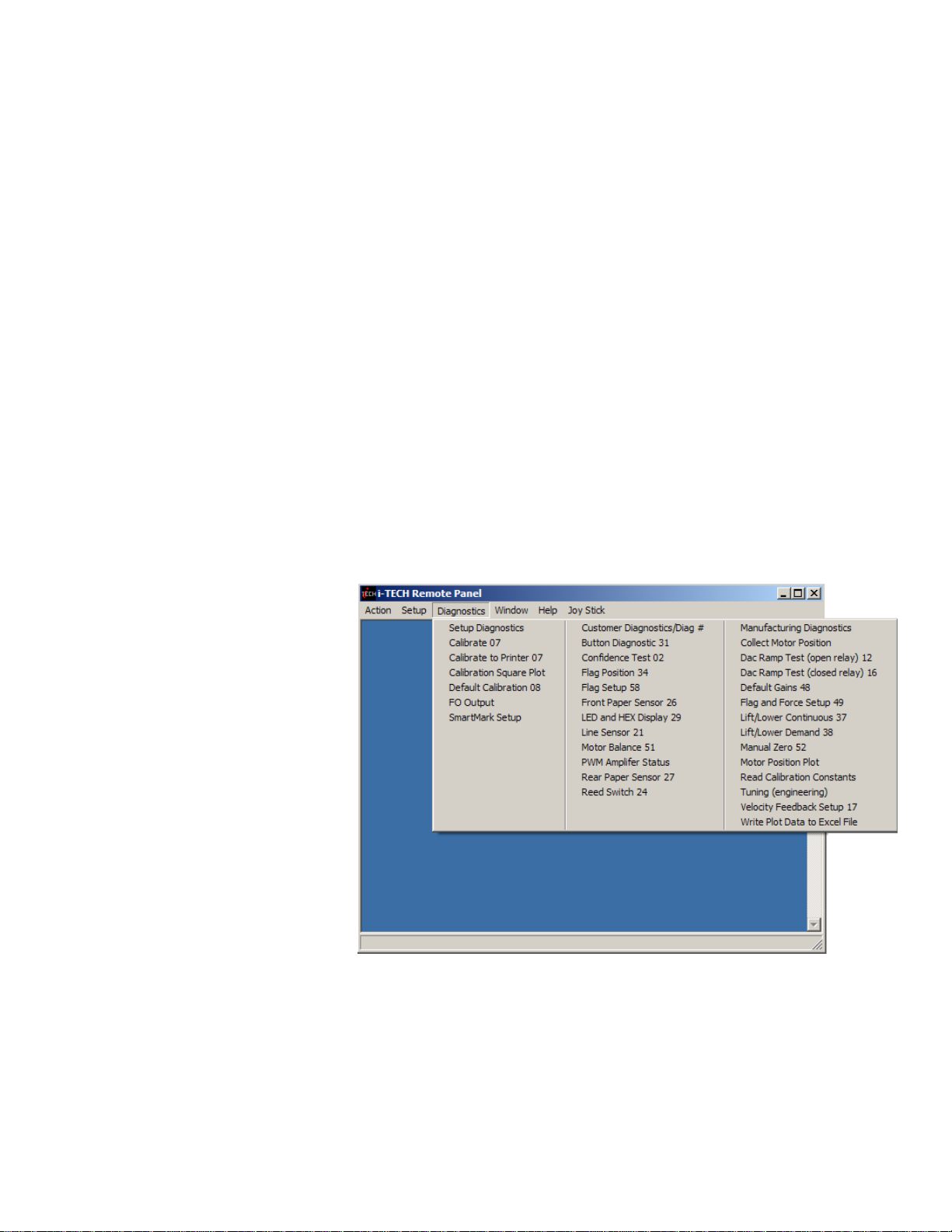
the drive motors and voice coil. In addition, a number of internal sensors are continually checked.
If any potentially damaging errors are detected, the system will cause the fail-safe circuits to open
the relay and idle the plotter. The appropriate error code will appear, as mentioned above, in the
display window on the control panel.
Diagnostic Operation
The diagnostics in the i-TECH Cutter exist at several levels:
a. POWER-ON
b. CONTINUOUS HARDWARE AND SOFTWARE MONITORING
c. OFF-LINE
The POWER-ON diagnostics are performed at power-on or reset of the microprocessor and test the
microprocessor, memory, servo analog and digital hardware, and some of the testable sensors.
After initialization, continuous hardware and software check the sensors and fail-safe monitors for
machine malfunctions. If a malfunction is detected, an error code is displayed on the control panel
display, the protection relay is opened, and the plotter ceases operation.
Control panel operation
Starting the diagnostics from Control Panel
Turn unit on and allow initialization to complete. If the i-TECH Cutter is displaying a flashing error code on the front panel display, press any key to enter the diagnostic mode.
Press the select key to initiate the menu function, Press the left or right arrow key to display diA.
Press the up or down key to scroll thru the diagnostic numbers (0002 – 0099). Press the select key
to start the diagnostic.
To Stop a Diagnostic
Press the reset key sequence
F1, F2, F3.
To Exit the
Diagnostic Mode
To return to normal operation,
run diagnostic 99 or cycle the
cutter power off and on.
Remote panel operation
Certain diagnostics are easier
to run from the remote panel.
To run the customer
diagnostics from the remote
panel program:
Open the remote panel
Open the Diagnostics Menu
IMPORTANT!! DO NOT run Manufacturing Diagnostics be run unless specifically instructed by direct contact with Allen Datagraph Technical support. Damage to the system is
possible if not run correctly.
Setup Diagnostics
Calibrate 07, Calibrate To Printer and SmartMark™ Setup have been described in other sec-
tions of this document or the SmartMark™ Setup Document.
36
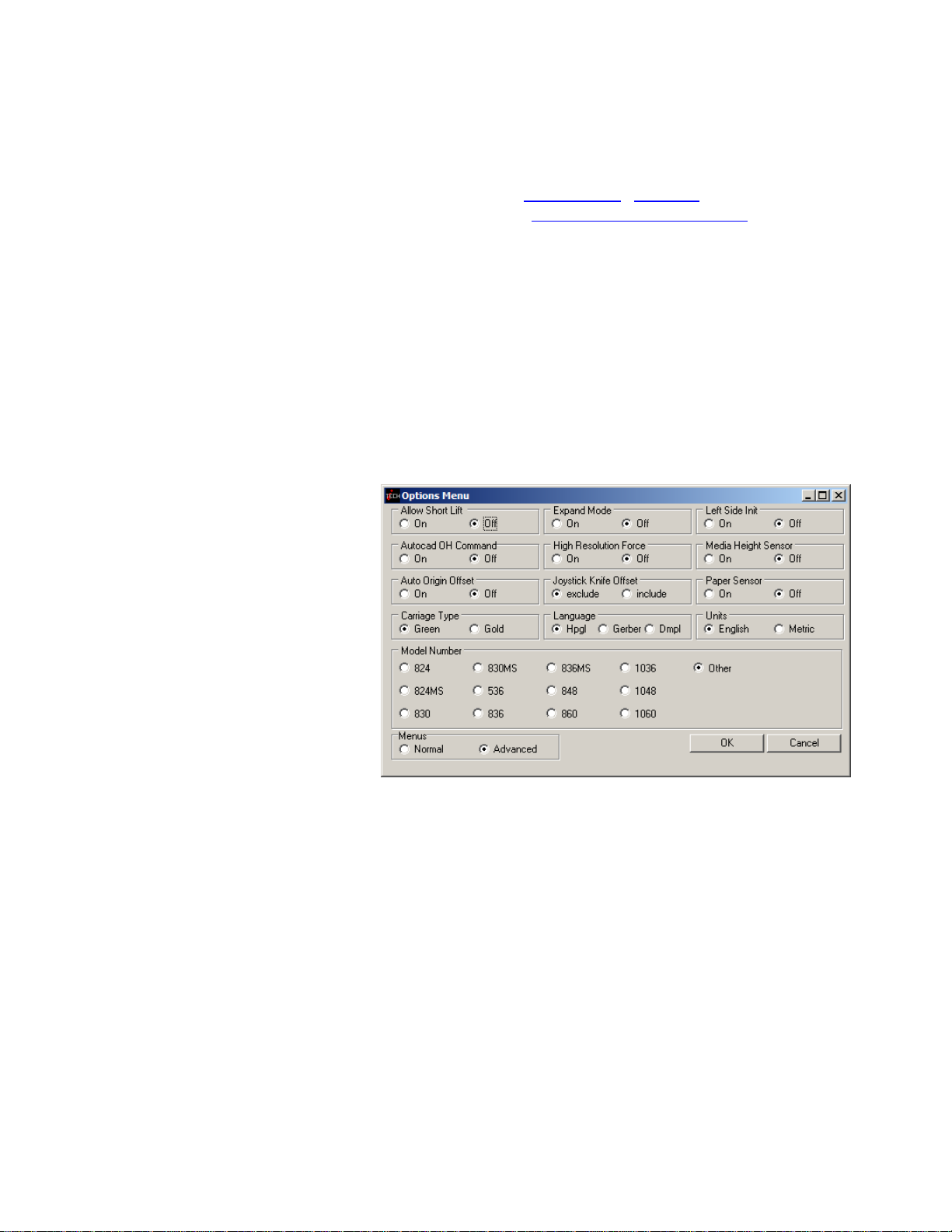
Calibration Square Output prompts for a square size and sends an HPGL command to output the
square. This is useful when calibrating the cutter to a ruler rather than a printer and is normally not
required. Specifying 10 inches for the size will send the HPGL command er10160,10160;
Default Calibration 08 diagnostic sets the calibration constants back to the factory defaults prior
to initial calibration. After running this diagnostic you will have to either restore the calibration
constants or rerun the calibration procedure described in
technical support page of the Allen Datagraph web site at
is a rather involved procedure Diagnostic 08 should be avoided unless you have received an E37
error, which requires this diagnostic to be run.
FO Output command sends the <esc>.vfooutput: command which displays software debug information about the last FO command. The first line output indicates the location of the three targets
and whether they were found. The last two lines indicate the amount of scaling and rotation calculated that need to be applied to the HPGL commands to cut the image.
Website Copy / CD Copy available on the
http://www.allendatagraph.com. As this
Customer Diagnostics
The “Customer Diagnostics” are designed for use by the customer to aid in trouble shooting the iTECH cutter..
To run a customer diagnostic, click on the menu item and the diagnostic will automatically start.
Some require intervention after starting and you will be given instructions on the screen.
Set Model Number 03
From the control panel scroll to
0003 and press the select key.
Enter model press the Select Key.
From the remote panel open the
Set-up menu then the Options
Menu. Click on the desired
Model Radio Button.
Button Diagnostic 31
Test the operation of each of the buttons on the front panel. Buttons must be pressed in the following order: Load, Pause, Copy, Speed Up, Speed Down, Force Up, Force Down, Test Cut, F3, F2,
F1, Select, Left, Right, Up, Down. If the wrong code is received the error code E036 is displayed
otherwise the requested button is requested with B0?? prompt.
Confidence Test 02
The confidence test is used to verify the operation of the cutting station of the i-TECH. It fully
tests the capability of the cutting CPU and Servo control system.
First Load paper at least 36 inches long into the cutter station. There is no need to fully load the iTECH. After loading the media into the cutter station do not press the load key. Insert a Pen into
the tool holder.
From the front panel scroll to 0002 press the Select Key. The i-TECH will start by sensing the
media width and then will draw a sample file. The file is distorted to fit the media width.
From the remote panel click on
media width and then will draw a sample file. The file is distorted to fit the media width.
Confidence Test 02. The i-TECH will start by sensing the
37 38

Flag Monitor / Adjust 34
This diagnostic is used to verify the correct flag position on the cutting head. It displays the knife
height on the display. The flag is a small, flat, angled piece of metal which moves up and down
between a pair of circuit board mounted sensors. The flag is held on to the knife holder by 2 Allen
screws, which are loosened slightly if adjustment is necessary. There are 3 locations the knife
holder can be in. They are:
Bottom (remove the knife from the holder and press the holder down to the bottom) The display
should read between 000 and 006. Adjust flag position if necessary
Down (press the knife down with a knife in the holder) The display should read 024 to 026 pressing down with a knife in the holder (no media present). Adjust flag position if necessary.
Top (hold the knife up) The display should read 060 or more.
The display should change immediately as you move the knife up or down.
Slightly move the flag to obtain the above reading at each of the three locations.
Check that the flag screws are tight and recheck Bottom and Down.
To start the diagnostic
From the front panel scroll to 0034 and press the Select Key.
.
From the remote panel click on
Flag Position 34.
Flag Setup - Z Axis 58
It is necessary to run Diagnostic 34 to verify carriage flag setting before performing this diagnostic. This diagnostic has the parts of diagnostic 49 necessary for field setup of the Z-axis without
opening the machine.
From the Front Panel scroll to 0058 then press the Select Key.
From the Remote Panel click on
Phase 4: Set Tool Bottom - Remove the tool from the holder and press the Select Key.
Phase 5: Set Tool Down - Adjust knife depth guide to equal the blade length. Place knife tool in
holder. Press the Select Key.
Phase 8: Balance X and Y Servos. See diagnostic 51
Power Down Cutter to continue.
Flag Setup 58.
LED and Hex display 29
Exercises the LEDS and the 4-character display.
Line Sensor 21
Continuously displays the result of the SmartMark™ Line sensor.
Motor Balance 51
The motor balance is a feature that automatic finds the servo balance DAC value for both the X and
Y-axes.
From the front panel first joy stick the Y-axis to the center of the workspace. Then scroll to
0051 and press the Select Key. The display will change to read 0008. At that point press the Select Key a second time. The carriage and the grit roller will oscillate back and forth multiple times,
first slowly and then more rapidly. It is possible that the carriage may bump the sidewall; this is
normal and will not affect the outcome. When the diagnostic is complete the cutter will reinitialize
and the carriage will return to the home position.

From the remote panel first joy stick the Y-axis to the center of the workspace. Click on “Motor
Balance 51”. The screen will change to the front panel simulator. Follow the instructions on the
screen. The carriage and the grit roller will oscillate back and forth multiple times, first slowly ant
then more rapidly. It is possible that the carriage may bump the sidewall; this is normal and will
not affect the outcome. When the diagnostic is complete the cutter will reinitialize and the carriage
will return to the home position.
PWM Amplifier Status
This displays the power amplifier status if the PWM power amplifier is installed.
Reed Switch 24
This diagnostic continuously displays the result of the media height sensor. As the reed switch
passes in front of a pinch wheel with a magnet installed, the output will change from 1 to 0.
Trouble Shooting
Problem Solutions
Cut through/poor weeding
• Is your knife blade sharp? You can check condition of blade by
examining the blade tip under a 30x microscope. The blade tip
must be present.
• For very thin (less than 0.002 inch, (0.05 mm)) media you might
need to use the controlled depth adjustment on the end of the
knife holder. Partially unscrew the black cap until just enough
knife blade is exposed to cut through the media but not the
backer. Test by drawing knife across media by hand. You can
then use a higher force with no cut through.
• It is important that the groove filler be installed fully and evenly,
otherwise material cut through may occur in some sections
across the plotter.
• Insufficient backer weight.
• Check mechanical adjustments
Website Copy / CD Copy
39

Error Codes
If the internal microprocessor detects an error condition, the letter E0 and a 2 digit code will be
displayed on the control panel. Any key pressed after the error is displayed will place the machine
in the diagnostic mode, indicated by a flashing "D" on the control panel. Recommended diagnostic
procedures (D##) are listed in the error description.
NONE all panel lights off - check PCBs loose in socket, fuses on main and power amp PCB,
115/230 VAC switch in wrong position, front panel PCB disconnected, loose cable from
power supply to motherboard PCB.
8.8:8.8
0000__power up display - check PCBs loose in socket,+ 5 volts, + 15 volts, + 32 volts, micro PCB
dead.
E001__Incorrect flash image
E002__Joystick Disabled
E003__pause switch on
E004__paper sensors must be on
E005__sheet not loaded
E006__media height sensor disabled
E007__buffer too small or cutter busy
E009__waiting for first vector to complete
E010__too much ambient light
E012__buffer overflow; communication, escape, down loadable character, or polygon buffer
E013__too many parameters in the escape command
E014 _invalid character in escape command
E015__escape command not implemented
E016__escape command parameter out of limits
E030__no media covering paper sensor
E032 __reed switch sensor malfunction – D024. Or pinch wheel under carriage too close to side
plate. Move pinch wheel away from side plate. See options menu to disable the media
height sensor.
E035__The pinch wheel positioned on an uncoated section of grit wheel. Reposition movable
pinch wheel. Right hand pinch wheel may be improperly situated or pinch wheel under car-
riage too close to side plate. Move pinch wheel away from side plate.
E036__bad control panel key received – D031.
E037__bad calibration constants Must run diagnostic D008, then calibrate i-TECH.
E039__pounce out of limits
E040__HPGL command parser error
E056 __RS-232 device overrun (broken cable, wrong handshake, broken serial hardware in com-
puter/ i-TECH)
E057 __RS-232 framing error. Plotter communications default for serial A port is 9600,n,8,1. set
software to match these parameters.
E058__RS-232 parity error
E059__EEROM checksum error
E061 __servo timeout. Cutter software error or servo PCB failure - D10. Check earth ground. Pre-
vent electrostatic discharge.
E062 servo motor over-current. Normally caused by paper jam. Check servo pot adjustment.
E063__Excessive current found in voice coil.
E065__EPO latch failure check seating of servo and CPU Board
40

E066__timeout latch failure check seating of servo and CPU Board
E067__voice coil current sensor failure check seating of servo and CPU Board
E068__servo motor over-current sensor failure check seating of servo and CPU Board
E069__EPO latch or EPO reset failure check seating of servo and CPU Board
E070__motor over-current - power amp failed check seating of servo and CPU Board
E071__voice coil over-current - pwr amp failed check seating of servo and CPU Board
E072__motor over-current, DAC or analog failed check seating of servo and CPU Board
E073__X-axis position counter failed check seating of servo and CPU Board
E074__Y-axis position counter failed check seating of servo and CPU Board
E075__X-axis encoder failed check seating of servo and CPU Board
E076__Y-axis encoder failed check seating of servo and CPU Board
E077__X-axis encoder detector failed check seating of servo and CPU Board
E078__Y-axis encoder detector failed check seating of servo and CPU Board
E079 __position initialization error; either carriage didn’t move or reed switch failed. Try with me-
dia height sensor disabled
E080, 81 Excessive position error - X axis, Y axis. Reference position of motor too far from
actual position of motor. This can be caused by speed or acceleration too high, jerking ma-
terial from a heavy roll, media jam, bad calibration constants, power surge, servo motor /
encoder failure, servo PCB failure, power amplifier pcb failure, relay on motherboard.
E082__servo interface bus error
E083__unexpected arithmetic fault
E084__unexpected constant fault
E085__unexpected interrupt
E086__unexpected nmi Interrupt
E087__unexpected machine fault
E088__unexpected operation fault
E089__unexpected parallel interrupt
E090__unexpected protection fault
E091__unexpected real arithmetic fault
E092__unexpected reserved fault
E093__unexpected servo interrupt
E094__unexpected trace fault
E095__unexpected type fault
Appendix A Installation And Assembly Instructions
Website Copy / CD Copy
Website Copy / CD Copy
Website Copy / CD Copy
Appendix D Cart Assembly Instructions
Website Copy / CD Copy
Appendix B SmartMarkTM setup
Appendix C Loading Diagram
41

Appendix E Radio and Television Interference
NOTE: This equipment has been tested and found to comply with the limits for a Class A digital
device, pursuant to Part 15 of the FCC rules. These limits are designed to provide reasonable protection against harmful interference when the equipment is operated in a commercial environment.
This equipment generates, uses and can radiate radio frequency energy and, if not installed and
used in accordance with the instruction manual, may cause harmful interference to radio communications. Operation of this equipment in a residential area is likely to cause harmful interference in
which case the user will be required to correct the interference at his own expense.
In order to maintain compliance with FCC regulations shielded cables must be used with this
equipment. Operation with non-approved equipment or unshielded cables is likely to result in interference to radio & television reception.
This device complies with part 15 of FCC Rules. Operation is subject to the following two
conditions; (1) This device may not cause harmful interference, and (2) this device must accept any
interference received, including interference that may cause undesired operation.
Appendix F Model i-536 Addendum
Website Copy / CD Copy
Appendix G Model i-536 Adjustable Parameters
Website Copy / CD Copy
Website Copy / CD Copy
Appendix I Template Maker Supplement
Website Copy / CD Copy
Appendix H Hot Tip Instructions
42
 Loading...