


MODEL 230 FRICTION FEED
Allen Datagraph 230/315 Vinyl Cutter
MODEL 315 SPROCKET FEED
VINYL CUTTERS
INTRODUCTION
The Allen Datagraph Systems Model 230 and 315 Vinyl Cutters are high performance machines designed for the graphics professional to cut and draw on a wide variety of materials. The 230/315 cuts with a swivel knife or draws with various pens and markers.
The 230 utilizes a precision grit wheel system for positive tracking and movable pinch wheels for handling punched or unpunched materials in standard and nonstandard sizes. The Model 315 utilizes precision sprocket assemblies which accept the standard IBM compatible punch pattern as well as "universal punch" vinyls and Gerber 15" punched vinyl.
Most of the operational procedures are the same for both the 230 and 315 cutters, with the exception of the differences relating to the material transport method, and the ability of the 315 to produce pounce patterns with the optional pounce kit available from Allen Datagraph Systems.
A Model 315 addendum appears at the end of this manual, which outlines the different operational procedures relating specifically to the 315.
A thumb screw tool holder allows tools to be quickly and easily changed. The 230/315 uses HPGL command language for widespread compatibility and emulates the Roland CAMM-1, the Hewlett Packard 758x, and DMPL plotters. The Allen Remote Panel program provides direct user control of speed, force and position, as well as having a full gamut of diagnostics.
1
Allen Datagraph 230/315 Vinyl Cutter
FEATURES
Gold Touch Cutting Head
The Model 230 features Allen's exclusive Gold Touch Cutting head, which allows the user up to 550 grams of cutting pressure.
There are 2 modes to the force adjustment, which can be accessed through the Windows remote panel provided with the cutter. These modes are contained in the OPTIONS menu under SETUP in the remote panel program.
The two modes are listed as FORCE POT RANGE, high and low.
Low is sufficient for most vinyl cutting applications, and has a top cutting pressure of 250 grams at 100% on the cutter's force dial.
High has a top force of 550 grams, and is used when cutting heavier materials such as sandblast mask, magnetic sheeting, etc.
Modes Of Operation
The 230/315 Vinyl Cutter has two modes of operation: Cut and Draw. These modes may be activated by HPGL command in the sign making software or from the Allen Remote Panel program.
Flexible Material Type and Size
A wide variety of vinyls, films, papers, stencil, sandblast mask and banner materials can be handled by the 230 for cutting, drawing, plotting and banner making.
The 230 will handle sheets or rolls of material in widths from 3.5 inches (90 The The Model 230 accepts material from 3.5" (88.9mm) to 30 inches (762 mm) in width. The 230 automatically detects material width during the Load cycle by
2
Allen Datagraph 230/315 Vinyl Cutter
sensing the magnets located in the right and left pinch wheel brackets and will not attempt to move beyond this width. The frame length on roll media is not limited by software in the plotter. For use without the optional guide system, it is suggested that the frame size be limited to 10 feet (3 m).
The Model 315 is a fixed width cutter and accepts only 15 inch punched material.
Service Loop
The 230/315 Vinyl Cutter is capable of a top speed of 24 in/sec (60 cm/s). Material can not be pulled off a large supply roll accurately at this speed. The 230/315 can maintain a service loop of material so that the cutter does not pull off the supply roll during cutting. This loop allows higher speed cutting than can normally be attained on drum type plotters. The service loop feature may be activated in the Allen Remote Panel if so desired.
Serviceability
The 230/315 use a modular design to provide rapid fault diagnosis and component replacement, which insures minimum downtime and replacement cost. The 230/315 has extensive built-in self test capability to assure continuously high quality output. The Allen Remote Panel provides access to the machine's controls and diagnostics.
Custom Set-Ups
The 230 has three programmable SET-UPs which can be customized for convenient use of a variety of software, material and tool combinations. Control settings on the cutter are saved in a SET-UP and then recalled for simple control of machine parameters. SET-UP 1, which is the power up default, can be set for the most often used configuration. Set-Ups are accessed through the Windows Control Panel under the SETTINGS menu.
CAS Mode
The 230/315 has front panel control knobs for speed and force. The knobs have a CAS (Computer Aided Signmaking) position which allows the 200 Series's Speed and Force to be controlled remotely by your Signmaking software, provided that speed and force settings are available.
Alternate Coordinate Systems
3
Allen Datagraph 230/315 Vinyl Cutter
The 230/315 offers four coordinate systems for widespread compatibility with CAS (Computer Aided Sign making) software programs. Long X and Long Y coordinate systems are compatible with the cutter drivers for most CAS programs. Center Origin and Center Origin rotated 180o coordinate systems are compatible with plotter drivers for the Hewlett Packard 758x.
OPTIONS
Long Tracking Vinyl Guides (Model 230 only)
The Long Tracking Vinyl Guide option enables tracking and cutting of 150 yard (50 m) rolls of unpunched vinyls. It is adjustable for material widths of 3.5 inches (90 mm) to 1 inch (25 mm) greater than the model size. The guides have limited use for paper and punched vinyls because the edges of these materials are not as strong as unpunched vinyl and therefore can not be edge guided with the same reliable results.
Vinyl Cradle
The vinyl cradle provides a means of handling rolls of material. It can be used on a bench top.
Optional Alignment Sight for Contour Cutting (p/n PL-00-11-500)
The Alignment Sight fits into the 230/315 tool holder and allows for contour cutting of color printed vinyl. The cut is controlled by the users's CAS software and typically requires the alignment of the sight with one, two or 3 registration marks printed on the vinyl.
4

Allen Datagraph 230/315 Vinyl Cutter
INSTALLATION
INSPECTION
IMPORTANT: Inspect your shipping container for evidence of excessive rough handling that may have caused machine damage. If you suspect shipping damage, contact ALLEN DATAGRAPH or your sales representative and report the condition immediately. Do not discard the shipping container.
UNPACKING THE CUTTER
Remove the packaging material. Next, remove the plotter chassis by lifting the plotter from each end, and place the plotter on a flat surface. Remove the remaining parts and accessories from the shipping container and check against the packing list and accessory list below. If there is any part shortage, please report it immediately to ALLEN DATAGRAPH or your Allen Dealer.
STANDARD ACCESSORIES
The following standard accessories are supplied in the 230 Accessory Kit.
1 Model 230 CD ROM
(User Manual, Remote Panel, DirectCut Windows Driver, Firmware)
1 knife holder assembly
1 knife blade, 45 degrees
1 9 to 25 serial plotter cable for IBM PC
(MACINTOSH cable must be ordered separately)
1 AC power cord
1 felt tip pen
1 hex wrench kit
2 spare 3 amp slow-blow fuses (250 VAC)
Paper Clamp Installation (Model 230 Only)
POWER CONNECTION
5
Allen Datagraph 230/315 Vinyl Cutter
LONG TRACKING GUIDE ASSEMBLY (MODEL 230 ONLY)
The optional Long Tracking Guide System may be attached to your 230 Vinyl Cutter. Contact your Allen Datagraph dealer if you want this option.
A pictorial assembly instruction sheet is provided on the CD ROM in your cutter's accessory kit in Microsoft Word format.
Tools Required
Phillips head screw driver, 1/8" and a 3/32" hex wrench.
Parts In Kit
4 brackets: Right Front, Left Front, Right Rear, Left Rear
2rollers with guide discs and collars
2rollers without guide discs or collars 8 Phillips screws
Assembly
1.Use the 3/32" hex wrench to loosen the right pinchwheel assembly.
2.Move both pinchwheel assemblies to the middle of the machine.
3.Install 4 brackets with the Phillips screws in the locations indicated on the label. (Right Front bracket to the right front of the machine, etc.)
4.Install a roller with discs (black end to the right) in the front of the machine by inserting the rod and collar on the black end of the roller through the keyhole slot on the right front bracket.
5.Pull on the rod and collar to retract the left end rod so it will pass through the keyhole on the left front bracket. Position both ends of the rod at the bottom of the keyhole slots and release. Adjust as necessary by pulling on the right end of the rod.
6.Installation of the Rear roller with discs in the same.
7.The rollers without discs drop in the front and rear bracket slots.
8.Move the pinch wheels back to their original positions.
Note: The black end of all rods should be at the control panel side of the machine.
6

Allen Datagraph 230/315 Vinyl Cutter
Front View and Material Path
(OPTIONAL Long Tracking system shown)
Rear View and Material Path
Allen Datagraph 230/315 Vinyl Cutter
ELECTRICAL CONNECTION
CAUTION: ALWAYS USE A HIGH QUALITY SURGE PROTECTOR!!
The vinyl cutter power cord is a three conductor cable that incorporates a safety (earth) ground connection. For the machine to operate safely and correctly, the power cord must be plugged into an outlet that has an earth ground contact. Never plug the power cord into a two prong outlet by using a 3=2 cord adapter.
CAUTION: Never allow roll or sheet goods to rub on the power cord because the material can cut the cord causing an electrical fire hazard!
The 230/315 can be configured to operate from either of these power sources:
115 VAC / 48-66 Hz |
230 VAC / 48-66 Hz |
The 230/315 vinyl cutter is normally factory preset for the power requirements of the destination country. Always verify power input module setting.
If the power input setting requires changing, use the following instructions to reconfigure the power input module:
a.Disconnect the AC power cord from the fuse block on the power input end panel.
b.Remove the fuse by prying open the fuse block from the top.
c.Check fuse rating to insure that it matches the new power setting. Correct fuse ratings are: 250 volt 3 amp slow-blow fuse for 115 VAC or 250 volt 1.5 amp slow-blow fuses for 230 VAC.
d.Set the voltage jumper as required for the country of operation. Reassemble the power module so that the desired operation voltage is visible when installed.
e.Plug in the power cord. NOTE: If the power switch does not match the power source, one of two things will probably happen: 1.) If the power source is 220 or 240 and the switch is positioned for 115, the AC input fuse will blow when power is applied. No other damage to the plotter will occur (unless a blown fuse is not replaced with the same type and value). or 2.) If the power source is 100 or 120 and the switch is positioned for 230, the plotter will not operate, and none of the panel lights will illuminate when power is applied. The AC
8
Allen Datagraph 230/315 Vinyl Cutter
COMPUTER CONNECTION
System Interfacing
The 230/315 Vinyl Cutters use serial communications. The serial (RS-232) interface is used in the majority of CAD/CAS systems and is available on IBM PC and Macintosh computers. At this time, refer to your CAD/CAS software package to determine the interface requirements particular to that package and for the interfacing requirements to the ALLEN DATAGRAPH vinyl cutter. If the ALLEN vinyl cutter is not listed on the software menu, refer to requirements for HPGL plotters, CAMM-1 or HP 758X series. Alternately, the 230/315 can be set for DMPL operation. See diagnostic 05.
Serial (RS-232) Interfacing
The serial interface is factory preset for 9600 baud, no parity, 8 bits, 1 stop bit but may be altered with diagnostic 04. The 230/315, when used with the supplied plotter cable, automatically supports both HARDWARE and XON / XOFF software handshaking with the Allen Datagraph plotter cable. Alternately, a "null modem" cable (available at computer supply stores) may be used on the serial port for XON / XOFF communications.
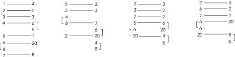
Serial (RS-232) Plotter Cables
The following configurations will provide proper communications with the 230
and 315. |
|
|
|
|
alternate |
|
|
|
|
|
|
|
|
|
|
IBM |
|
Macintosh |
|
IBM |
|
IBM |
|
9 Pin |
Plotter |
DIN-8 |
Plotter |
25 Pin |
Plotter |
25 Pin |
Plotter |
|
|
|
|
|
|
|
|
9
Allen Datagraph 230/315 Vinyl Cutter
OPERATION
MODES OF OPERATION
The 230/315 has 2 modes of operation for control of its corresponding tools: knife and pen. CUT MODE is used for knife offset cutting and DRAW MODE is used for pen plotting and wide marker drawing.
The Allen Remote Panel program indicates the current MODE on the Main Menu.
Knife Cutting (CUT MODE)
Knife offset cutting is performed in the CUT MODE. The CUT MODE provides the OFFSET a swivel knife needs to cut corners and curves accurately. The offset is nominally 0.012 inches (0.3 mm) which is expressed as an offset of 12. The knife offset can be set from 0 to 100 plotter units.
If the 230/315 is in the CUT MODE and the CAD/CAS package is also providing a swivel knife offset, the user will have unsatisfactory cut quality. Choose to control knife offset with either the plotter or CAS software. (While not recommended, for CAS offset control, use the 230/315 in the Draw Mode.)
Pen Plotting and Wide Marker (DRAW MODE)
Pen plotting and wide marker drawing are performed in the DRAW MODE. Check plots or colorful graphics may be made with either HP (Hewlett Packard) style roller ball or felt tip pens. For best results, remove the groove filler strip when plotting.
For banner making with the wide markers, the optional marker holder is required. This holder fits in place of the usual tool holder.
LOAD MATERIAL MODEL 315
The 315 by default will power up in the LOAD state. This is indicated by the LOAD light being illuminated. It is not necessary to press the load key prior to sending a job top the cutter.
To load material on a Model 315, first position the cutting head to the center of the sprockets.
Pivot the retainers away from the material hold downs, and open the hold downs.
Insert the material from the rear of the machine, positioning the material onto the sprocket teeth.
Close the hold downs, and pivot the retainers over the hold downs. |
10 |
Allen Datagraph 230/315 Vinyl Cutter
LOAD MATERIALMODEL 230
Unpunched Material
Turn the cutter on before loading media. The cutter will energize the vacuum fan and move the cutting head full right. The cutter is now ready for loading media.
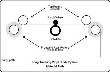
1.Place roll material on the roll supply and feed the material from the back of the machine and then under the pinch wheels until it is inserted 1-2 feet (30-60 cm). A material path diagram follows. Position the right edge of the material against the black vinyl front and rear edge guide strip. Also, visually align the roll of goods with the edge guide. NOTE: Proper alignment with the guide will give the best results when making long images.
2.Position the left pinch wheel at the left edge of the material. This pinch wheel should be positioned so that its edge is about 1/4 inch (6 mm) in from the edge of the material. The material must be at least 3.5 inches wide (9 cm).
3.Lower the pinch wheel lever.
4. Use the joystick buttons to position the tool to the desired start point.
5.Press the LOAD button. The 230 measures the material width (Y-axis) and then the material moves back and forth (X-axis) 1 inch (25 mm), unless a different Load Length has been set with the Allen Remote Panel program. The tool will position to the starting point of the current coordinate system. (See ORIGIN LOCATION section of this manual.)
6.To perform a cut test pattern, press the TEST button. Move the head out of the way by using your joystick buttons, and then weed the cut test. Make force changes by rotating the FORCE knob left or right as necessary to get the correct cutting depth.
Detailed illustrations and explanations of the cut test are found on page 16.
To unload material, press PAUSE and then LOAD. Raise the pinch wheel lever.
11

Allen Datagraph 230/315 Vinyl Cutter
Punched Material(Model 230)
Turn the cutter on before loading media. The cutter will energize the vacuum fan and move the cutting head full right. The cutter is now ready for loading media.
1.Place roll material on the roll supply and feed the material from the back of the machine and then under the pinch wheels until it is inserted 1-2 feet (30-60 cm). Position the right edge of the material against the front and rear edge guide strip. Also, visually align the roll of goods with the edge guide. NOTE:
Proper alignment with the guides will give the best results when making long images.
2.Position the left pinch wheel further in so that the wheel does not run on the holes of the material. Move the right pinch wheel in so that it does not run over the holes of the material.
3.Lower the pinch wheel lever.
4.Use the joystick buttons to position the tool to the desired start point.
5.Press the LOAD button. The 230 measures the material width (Y-axis) and then the material moves back and forth (X-axis) 1 inch (25 mm), unless a different Load Length has been set with the Allen Remote Panel program. The tool will position to the starting point of the current coordinate system. (See ORIGIN LOCATION section of this manual.)
6.To perform a cut test pattern, press the TEST button. Make changes as necessary to get correct cutting force and depth.
Detailed illustrations and explanations of the cut test are found on page 16.
To unload material, press PAUSE and then LOAD. Raise the pinch wheel lever.
12
Allen Datagraph 230/315 Vinyl Cutter
Long Tracking Vinyl Guide System (Optional230 Only)
The optional Long Tracking Guide System enables the cutting of full rolls of material wider than 3.5 inches (9 cm). Vinyl rolls without sprocket holes are best suited for use in this system. Light weight paper and material with too many holes have weak edges and do not work as well. The following points should be noted:
1.Right front and rear edge guide discs are fixed. Left front and rear guide discs are movable by hand. All front and rear rollers are removable. When reinstalling rollers, be sure that the black ends are at the right side of the machine.
2.Place vinyl against right front and rear guide discs.
3.Adjust the left front and rear guide discs to material edge. Left guide discs move with moderate pressure. No tools are required. Allow approximately 1/16 inch (1 to 2 mm) space for material variation.
4.Test tracking with the joystick buttons for 3-4 feet (1 m). Material should not bind at any of the guides. Adjust left guides and the supply roll alignment as necessary. If left guide discs are moved by the vinyl, they may be tightened slightly with a 1/8" hex wrench but should still move by hand. The right front and rear guide discs need to be an equal distance from the right side plate for long tracking.
13
Allen Datagraph 230/315 Vinyl Cutter
Service Loop
A service loop is slack in the material coming off the supply roll. The plotter needs this slack to maintain accurate cutting and tracking. The 230/315 can automatically maintain a service loop when this feature is activated. During a service loop material advance, the tool is raised and material is advanced. This speed reduction during material advance off the supply roll allows fast cutting over long lengths.
The service is set to default to OFF. If you feel it is necessary to activate it, the service loop feature is activated from the Set Up Menu of the Allen Remote Panel program by turning the service loop "on".
The service loop feature may be deactivated three ways;
1. Turn the Service Loop to "off" from the Set Up Menu of the Allen Remote Panel program.
2.Use the joystick buttons to jog the size of an entire job.
3.Set a Media Load Length to the size of an entire job before loading media.
Example: To cut a 10 foot sign without the service loop, the user may a). set a MEDIA LOAD LENGTH of 10 feet 3 inches or b). load the standard 2 feet (61 cm) and then spool the material with the joystick buttons until the 10 feet 3 inches have been reached. With the joystick method the user must return the tool to the cut start position after the desired cut length has been spooled.
Media Load Length
The MEDIA LOAD LENGTH may be set to any size from 1 to 100 inches or from 1 to 254 cm. For example, with a 48 inch MEDIA LOAD LENGTH, the cutter pulls out 48 inches (122 cm) of material. For long runs of material, tracking can be verified before cutting by setting the LOAD LENGTH equal to the entire image output length. Alternately, tracking may be checked with the joystick buttons.
A MEDIA LOAD LENGTH value may be adjusted for each of SET-UPS 1-3. Set the Load Length in either inches or centimeters using the Set Up Menu of the Allen Remote Panel program. Load the material as usual.
The plotter will load the entire MEDIA LOAD LENGTH specified. If the service loop is on (Set up Menu), the service loop will not be activated until after the 24 inch distance has been traveled.
14
Allen Datagraph 230/315 Vinyl Cutter
LOAD TOOLS
Knife
Summary
1.Install knife blade in knife holder.
2.Load material.
3.Set machine to REMOTE STATE.
4.Install knife assembly.
5.Set machine to CUT MODE.
6.Perform test pattern.
CAUTION: Avoid personal injury. Keep hands, hair, clothing and jewelry away from the cutter's moving parts.
Knife
Holder
Depth
Guide
Blade
Cutting Strip
Knife Assembly
The knife holder uses a thrust bearing design to ensure proper movement of the knife blade in use. Solvents and lubricants should not be used as they will diminish cutting accuracy. The knife holder is designed for use with Allen Datagraph’s 45 and 60 degree blades.
The depth guide allows the user to limit the depth that the knife will cut into a given material. The correct setting of the depth guide allows the knife blade to cut only the material and not the backer (carrier) material.
Knife Blades
New blades slide into the knife assembly to a preset height and are held in magnetically. No tools or adjustments are required. To remove old blades, remove the depth guide from the knife holder assembly and pull the blade out by holding the knife holder with the flat side of the blade facing up. Grasp the blade using your forefinger and thumb and pull the blade from the holder.
Knives for the Allen Datagraph Vinyl Cutters are designed specifically for offset cutting. The tip is offset from the center of the shaft so that the blade has a caster action when pulled. Blades are available in 45 and 60 degree tip angles. The 60 degree is intended thicker materials such as sandblast mask. For best cutting results, protect the knife tip from damage when not in use by unscrewing the black cap.
15

offset correct
offset too high
offset too low
Allen Datagraph 230/315 Vinyl Cutter
KnifeOffset
This figure shows the path the pen takes and the path the knife takes at a corner. If pen plots have the characteristic of the knife path, it is likely that the cutter is in the CUT MODE. The Pen path has no offset compensation.
Change CUT and DRAW modes with the Allen Remote Panel program.
Cut Test Pattern
A test pattern is provided to verify cut quality. The pattern can be positioned with the joystick buttons when the cutter Load light is on and pause light off. Repeat the test as necessary to check blade quality, fine tune force, offset and blade depth. The cutter should produce a test pattern which has accurate corners, smooth curves and is easy to "weed" out. The material carrier should be marked lightly and evenly.
To make the test pattern, load material with the LOAD button and then press the TEST button.
If the corners of the test pattern (or lettering) have misshaped corners when knife cutting, adjust the knife offset using the Allen Remote Panel Program.
If the blade offset is too high, the corners will be extended and the circles will have bumps. In that case, reduce the knife offset. For example, if the original offset is 12 and the output shows signs of too much offset, try an offset of 10 (or less).
If the blade offset is too low, the corners will be rounded and the circles will have nicks. In that case, try an offset of 14 (or more).
If a good test pattern cannot be achieved in this manor, inspect the knife blade and replace as necessary.
16
Allen Datagraph 230/315 Vinyl Cutter
Plotter Pens
In the Draw Mode, the 230 and 315 are high performance drafting plotters capable of producing professional architectural and engineering drawings. HP style pens used by the 230 and 315 are available as drafting, felt tip and roller ball type. Speed and force requirements vary for these pens and a chart is provided for your reference.
Drafting pens are held in the tool holder block or the wide marker block.
PenType |
Speed |
Force |
Felt tip |
40-50 |
10-20 |
Roller Ball |
40-50 |
30-50 |
Drafting |
30-40 |
8-12 |
Wide Marker Holder
Mounting the Optional Marker Holder
The marker holder is mounted by first removing the knife tool holder block (two hex head screws). Install the wide marker holder using the same hex screws. Adjust the height of the wide marker in the holder vertically so that it is about 1/8 inch (3mm) above the material.
Wide Marker Drawing
Wide marker drawing is done in the Draw mode. Align the pen so that rectangular tip is perpendicular to the fill lines of the marker.
Test a stroke of the pen by pushing TEST. If the stroke is not smooth, adjust the height or lightly sand the face of the tip.
Pen speed and proper background material are critical elements to a good plot. The suggested range of speed for wide marker pens is from 8 to 30 cm/sec (10 to 45 on the Control Panel) depending on the type of material and the amount of ink left in the pen. A speed of 25 cm/s (10 inch/sec) should produce satisfactory results on most surfaces. If satisfactory results are not produced, you may need to slow the speed down, replace / refill the pen, or lightly sand the nib. The background material should be smooth paper, vinyl or coated TYVEK.
17
Allen Datagraph 230/315 Vinyl Cutter
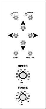
CONTROL PANEL
Load and Pause
These two buttons and associated lights allow the user to control the machine's operating states:
No lights on This is the UNLOADED state; material is removed or inserted. Upon power up the plotter is in this state. To go to the Remote state, load material and press the Load button.
LOAD light on This is the READY state; material has been loaded, programming commands can be received and executed. To pause machine operation (i.e.. go to the View state), press the Pause button.
PAUSE light on This is the view or PAUSED state; material has been loaded, commands from the computer are received but plotting is suspended. The joystick buttons may be used to move material for viewing
without affecting the position 230/315 Control Panel when plotting is resumed. The
pinch wheels may be raised and lowered to adjust material tracking. To return to cutting (i.e.. go to the Remote state) press the Pause button again.
PAUSE blinking Data is being received.
18
Allen Datagraph 230/315 Vinyl Cutter
Speed Control
The machine's Speed settings are 1 to 100. Step 1 is the slowest and step 100 is the fastest. In the 1 to 100 position, the speed is controlled by the knob and computer commands (CAS), including the Allen Remote Panel program, are ignored. The speed knob controls up and down speed in unison. Changes in the control knob position made during cutting will take effect after up to 200 vectors have been plotted. For best results, preset the knob before plotting.
In the CAS position, the machine function is controlled by computer software. If no speed command is sent, the speed will be the last one sent since power up. If no speed command has been sent since power up, then the default from Setup 1 will be used. The current value and the speed default can be changed with the Allen Remote Panel program. Up and down speed may be controlled individually in the CAS position.
For more information, see the CAS control section of Software Notes in this manual.
Force Control
The machine's Force settings are 1 to 100. Step 1 is the lightest (approximately 10 grams) and step 100 is the heaviest (550 grams). In the 1 to 100 position, the force is controlled by the knob and computer commands (CAS), including Allen Remote Panel program, are ignored. Changes in the control knob position made during cutting will take effect almost immediately. For best results, preset the knob and perform a test cut before plotting.
In the CAS position, the force function is controlled by computer software. If no force command is sent, the force will be the last one sent since power up. If no force command has been sent since power up, then the default from Setup 1 will be used. The current value and the machine default can be changed in the Allen Remote Panel program's Settings menu.
For more information, see the CAS control section of Software Notes in this manual.
Joystick Buttons (Tool Position)
Four buttons are arranged in the center of the control panel to move the tool position left, right, front and back. These buttons control the cut start point (origin) in Load (the READY state). In the PAUSED state, the buttons control the temporary tool position for viewing. If the joystick buttons are pressed in PAUSE and then the Pause button is pressed again to return to cutting, the tool will return to the correct cutting position.
Small move ................... |
tap joystick button |
Slow move .................... |
hold joystick button |
Fast move ..................... |
tap and then hold joystick button |
For a Fast move, the longer the button is held (after a tap), the faster the tool will move. However, the
19
Allen Datagraph 230/315 Vinyl Cutter
tool will move at a fixed rate when the button of the opposing direction is held at the same time.
Copy
This button allows the contents of the buffer to be replotted. Some software packages do not automatically clear the buffer when a new job is sent. To insure that only one job will be cut when the copy button is pressed, make sure that only the desired job has been sent to the cutter prior to attemting to copy a job.
This can be accomplished by pressing pause, unload, and then load again to reload the cutter. Every time the cutter is reloaded, the buffer is cleared.
Test
This button performs the cut test pattern to verify blade condition and depth adjustment as well as Force and Offset settings.
20
Allen Datagraph 230/315 Vinyl Cutter
The Allen Remote Panel Program
The 230/315 has many settings for machine control which are accessed by the Allen Remote Panel program. Use the serial cable supplied with the 230/315 and connect it to the Serial port.
To run the Allen Remote Panel program on a Windows PC, follow the installation instructions in the next section of this manual.
For a non-Windows computer or a Windows PC running a communications program other than the Allen Remote Panel program, the Allen Remote Panel menus may be accessed with any RS-232 serial communications program. The following commands have keyboard equivalents as shown. The commands "esc" and "control" are single keys on the computer keyboard.
Initialize ........................ |
esc.a esc.) |
Terminate ..................... |
esc |
Reset ............................ |
control c |
Exit diagnostics ............ |
control b |
Machine Control by the Allen Remote Panel program
21

Allen Datagraph 230/315 Vinyl Cutter
Installing the Allen Remote Panel Program with Windows 98, XP, 2000
To install the Allen Remote Panel Program, insert the CD ROM into the computer. If it does not autorun, go to START, RUN, BROWSE.
Locate your CD ROM drive on your computer, double click the Setup Allen Cutter.exe icon(circled, below). This will either be a blue and red icon or it could possibly be a zip file, which will have a zip file icon. In the case of the zip file, it must first be unzipped using Winzip or comparable program. It can then be extracted to your desktop.
Once extracted, you can double click the Setup Allen Cutter icon.
The Install shield program will guide you through the rest of the installation.
When installation is complete, a shortcut to the program will be placed on your computer's desktop. If, for some reason the shortcut is not found there, the program may be launched from the Windows Program Menu. (Start, Programs, Allen Datagraph, Allen Remote Panel).
NOTE: The 230/315 Cutter's serial cable MUST BE CONNECTED TO COM1 or COM2 and the cutter must be ON for the program to function.
The first time the program is run, select the correct port under SETUP, COM PORT in the Remote Panel's main screen.
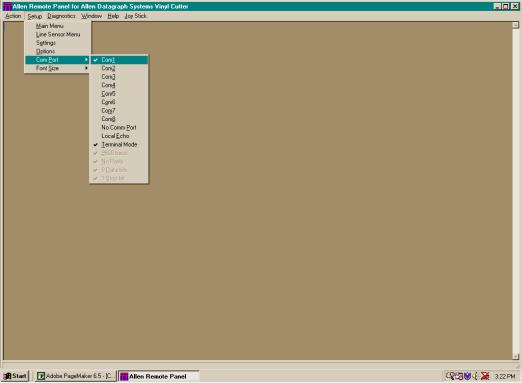
Allen Datagraph 230/315 Vinyl Cutter
The 230/315 Cutter's serial cable MUST BE CONNECTED TO COM1 or COM2 for the program to function.The first time the program is run, select the correct port under SETUP, COM PORT (below).
All machine functions can be controlled from the Remote Panel when the 230/315 is turned on and connected to a serial port, provided the cutter and/or the computer port are not busy.
23
 Loading...