

Page 1

SLC 500 Hardware Migration
Bulletins 1746, 1747, 1769, 5069
Reference Manual
Original Instructions
Page 2
SLC 500 Hardware Migration Reference Manual
Important User Information
Read this document and the documents listed in the additional resources section about installation, configuration, and
operation of this equipment before you install, configure, operate, or maintain this product. Users are required to familiarize
themselves with installation and wiring instructions in addition to requirements of all applicable codes, laws, and standards.
Activities including installation, adjustments, putting into service, use, assembly, disassembly, and maintenance are required to
be carried out by suitably trained personnel in accordance with applicable code of practice.
If this equipment is used in a manner not specified by the manufacturer, the protection provided by the equipment may be
impaired.
In no event will Rockwell Automation, Inc. be responsible or liable for indirect or consequential damages resulting from the use
or application of this equipment.
The examples and diagrams in this manual are included solely for illustrative purposes. Because of the many variables and
requirements associated with any particular installation, Rockwell Automation, Inc. cannot assume responsibility or liability for
actual use based on the examples and diagrams.
No patent liability is assumed by Rockwell Automation, Inc. with respect to use of information, circuits, equipment, or software
described in this manual.
Reproduction of the contents of this manual, in whole or in part, without written permission of Rockwell Automation, Inc., is
prohibited.
Throughout this manual, when necessary, we use notes to make you aware of safety considerations.
WARNING: Identifies information about practices or circumstances that can cause an explosion in a hazardous environment, which may
lead to personal injury or death, property damage, or economic loss.
ATTENTION: Identifies information about practices or circumstances that can lead to personal injury or death, property damage, or
economic loss. Attentions help you identify a hazard, avoid a hazard, and recognize the consequence.
IMPORTANT
Identifies information that is critical for successful application and understanding of the product.
Labels may also be on or inside the equipment to provide specific precautions.
SHOCK HAZARD: Labels may be on or inside the equipment, for example, a drive or motor, to alert people that dangerous voltage may
be present.
BURN HAZARD: Labels may be on or inside the equipment, for example, a drive or motor, to alert people that surfaces may reach
dangerous temperatures.
ARC FLASH HAZARD: Labels may be on or inside the equipment, for example, a motor control center, to alert people to potential Arc
Flash. Arc Flash will cause severe injury or death. Wear proper Personal Protective Equipment (PPE). Follow ALL Regulatory requirements
for safe work practices and for Personal Protective Equipment (PPE).
2 Rockwell Automation Publication 1746-RM003E-EN-E - August 2020
Page 3

Table of Contents
Preface
About This Publication . . . . . . . . . . . . . . . . . . . . . . . . . . . . . . . . . . . . . . . . . . . 5
Audience . . . . . . . . . . . . . . . . . . . . . . . . . . . . . . . . . . . . . . . . . . . . . . . . . . . . . . . . 5
Required Software . . . . . . . . . . . . . . . . . . . . . . . . . . . . . . . . . . . . . . . . . . . . . . . 5
Summary of Changes. . . . . . . . . . . . . . . . . . . . . . . . . . . . . . . . . . . . . . . . . . . . . 6
Additional Resources . . . . . . . . . . . . . . . . . . . . . . . . . . . . . . . . . . . . . . . . . . . . . 7
Chapter 1
Overview Product Lifecycle Status Website . . . . . . . . . . . . . . . . . . . . . . . . . . . . . . . . . . 9
SLC 500 System. . . . . . . . . . . . . . . . . . . . . . . . . . . . . . . . . . . . . . . . . . . . . . . . . 10
CompactLogix 5370 Controllers . . . . . . . . . . . . . . . . . . . . . . . . . . . . . . . . . . 10
CompactLogix 5380 Controllers . . . . . . . . . . . . . . . . . . . . . . . . . . . . . . . . . . 10
Compact I/O Modules . . . . . . . . . . . . . . . . . . . . . . . . . . . . . . . . . . . . . . . . . . . 11
Compact 5000 I/O Modules . . . . . . . . . . . . . . . . . . . . . . . . . . . . . . . . . . . . . . 11
Power Considerations . . . . . . . . . . . . . . . . . . . . . . . . . . . . . . . . . . . . . . . . . . . 12
SLC 500 Controllers. . . . . . . . . . . . . . . . . . . . . . . . . . . . . . . . . . . . . . . . . . 12
CompactLogix 5380 Controllers . . . . . . . . . . . . . . . . . . . . . . . . . . . . . . . 12
Sensor Actuator Power for CompactLogix 5380 . . . . . . . . . . . . . . . . . 13
Other Considerations . . . . . . . . . . . . . . . . . . . . . . . . . . . . . . . . . . . . . . . . 14
Chapter 2
Replace an SLC 500 Controller Upgrade to a CompactLogix 5370 Controller . . . . . . . . . . . . . . . . . . . . . . . 15
Upgrade to a CompactLogix 5380 Controller . . . . . . . . . . . . . . . . . . . . . . . 16
Chapter 3
Replace an SLC 500 I/O Module Upgrade an SLC I/O Installation by Replacing it with Compact I/O . . 17
Upgrade an SLC I/O Installation by Replacing it with
Compact 5000 I/O . . . . . . . . . . . . . . . . . . . . . . . . . . . . . . . . . . . . . . . . . . . . . . 20
SLC I/O Installation Using a Conversion Kit. . . . . . . . . . . . . . . . . . . . 23
Appendix A
Wiring Diagram Comparisons Replace an SLC 5 Processor Serial Port with a Compact I/O
Serial Module. . . . . . . . . . . . . . . . . . . . . . . . . . . . . . . . . . . . . . . . . . . . . . . . . . . 25
SLC 5/03, SLC 5/04, or SCL 5/05 to 5069-SERIAL . . . . . . . . . . . . . 25
Replace an SLC 500 I/O with a Compact I/O . . . . . . . . . . . . . . . . . . . . . . . 26
1746-IA4 to 1769-IA8I. . . . . . . . . . . . . . . . . . . . . . . . . . . . . . . . . . . . . . 26
1746-IA8 to 1769-IA8I. . . . . . . . . . . . . . . . . . . . . . . . . . . . . . . . . . . . . . 26
1746-IA16 to 1769-IA16 . . . . . . . . . . . . . . . . . . . . . . . . . . . . . . . . . . . . . 27
1746-IB8 to 1769-IQ16 . . . . . . . . . . . . . . . . . . . . . . . . . . . . . . . . . . . . . 27
1746-IB16 to 1769-IQ16. . . . . . . . . . . . . . . . . . . . . . . . . . . . . . . . . . . . . 28
1746-IG16 to 1769-IG16 . . . . . . . . . . . . . . . . . . . . . . . . . . . . . . . . . . . . 28
1746-IM4 to 1769-IM12 . . . . . . . . . . . . . . . . . . . . . . . . . . . . . . . . . . . . 29
1746-IM8 to 1769-IM12 . . . . . . . . . . . . . . . . . . . . . . . . . . . . . . . . . . . . 29
1746-IM16 to 1769-IM12. . . . . . . . . . . . . . . . . . . . . . . . . . . . . . . . . . . . 30
Rockwell Automation Publication 1746-RM003E-EN-E - August 2020 3
Page 4

Table of Contents
1746-ITB16 to 1769-IQ16F . . . . . . . . . . . . . . . . . . . . . . . . . . . . . . . . . . 30
1746-ITV16 to 1769-IQ16F . . . . . . . . . . . . . . . . . . . . . . . . . . . . . . . . . . 31
1746-IV8 to 1769-IQ16 . . . . . . . . . . . . . . . . . . . . . . . . . . . . . . . . . . . . . 31
1746-IV16 to 1769-IQ16. . . . . . . . . . . . . . . . . . . . . . . . . . . . . . . . . . . . . 32
1746-OA8 to 1769-OA8 . . . . . . . . . . . . . . . . . . . . . . . . . . . . . . . . . . . . . 32
1746-OA16 to 1769-OA16 . . . . . . . . . . . . . . . . . . . . . . . . . . . . . . . . . . . 33
1746-OB8 to 1769-OB8. . . . . . . . . . . . . . . . . . . . . . . . . . . . . . . . . . . . . 33
1746-OB16 to 1769-OB16 . . . . . . . . . . . . . . . . . . . . . . . . . . . . . . . . . . . 34
1746-OB16E to 1769-OB16P. . . . . . . . . . . . . . . . . . . . . . . . . . . . . . . . . 34
1746-OBP8 to 1769-OB8. . . . . . . . . . . . . . . . . . . . . . . . . . . . . . . . . . . . 35
1746-OG16 to 1769-OG16 . . . . . . . . . . . . . . . . . . . . . . . . . . . . . . . . . . . 35
1746-OV8 to 1769-OV16 . . . . . . . . . . . . . . . . . . . . . . . . . . . . . . . . . . . . 36
1746-OV16 to 1769-OV16 . . . . . . . . . . . . . . . . . . . . . . . . . . . . . . . . . . . 36
1746-OW4 to 1769-OW8 . . . . . . . . . . . . . . . . . . . . . . . . . . . . . . . . . . . 37
1746-OW8 to 1769-OW8 . . . . . . . . . . . . . . . . . . . . . . . . . . . . . . . . . . . 37
1746-OW16 to 1769-OW16 . . . . . . . . . . . . . . . . . . . . . . . . . . . . . . . . . . 38
1746-IO2DC to 1769-IQ6XOW4. . . . . . . . . . . . . . . . . . . . . . . . . . . . . 38
1746-NI4 to 1769-IF4 . . . . . . . . . . . . . . . . . . . . . . . . . . . . . . . . . . . . . . 39
1746-NIO4I to 1769-IF4XOF2. . . . . . . . . . . . . . . . . . . . . . . . . . . . . . . 39
1746-NIO4V to 1769-IF4XOF2 . . . . . . . . . . . . . . . . . . . . . . . . . . . . . . 40
1746-NI8 to 1769-IF8 . . . . . . . . . . . . . . . . . . . . . . . . . . . . . . . . . . . . . . 40
1746-NO4I to 1769-OF4 . . . . . . . . . . . . . . . . . . . . . . . . . . . . . . . . . . . . 41
1746-NO4V to 1769-OF4 . . . . . . . . . . . . . . . . . . . . . . . . . . . . . . . . . . . 41
Replace an SLC 500 I/O with a Compact 5000 I/O . . . . . . . . . . . . . . . . . . 42
1746-IA4 to 5069-IA16 . . . . . . . . . . . . . . . . . . . . . . . . . . . . . . . . . . . . . 42
1746-IA8 to 5069-IA16 . . . . . . . . . . . . . . . . . . . . . . . . . . . . . . . . . . . . . 42
1746-IA16 to 5069-IA16 . . . . . . . . . . . . . . . . . . . . . . . . . . . . . . . . . . . . 43
1746-IM4 to 5069-IA16. . . . . . . . . . . . . . . . . . . . . . . . . . . . . . . . . . . . . 43
1746-IM8 to 5069-IA16. . . . . . . . . . . . . . . . . . . . . . . . . . . . . . . . . . . . . 44
1746-IM16 to 5069-IA16 . . . . . . . . . . . . . . . . . . . . . . . . . . . . . . . . . . . . 44
1746-IB8 to 5069-IB16 . . . . . . . . . . . . . . . . . . . . . . . . . . . . . . . . . . . . . 45
1746-IB16 to 5069-IB16 . . . . . . . . . . . . . . . . . . . . . . . . . . . . . . . . . . . . 45
1746-ITB16 to 5069-IB16 . . . . . . . . . . . . . . . . . . . . . . . . . . . . . . . . . . . 46
1746-OA8 to 5069-OA16. . . . . . . . . . . . . . . . . . . . . . . . . . . . . . . . . . . . 46
1746-OA16 to 5069-OA16 . . . . . . . . . . . . . . . . . . . . . . . . . . . . . . . . . . . 47
1746-OB8 to 5069-OB8 . . . . . . . . . . . . . . . . . . . . . . . . . . . . . . . . . . . . 47
1746-OBP8 to 5069-OB8 . . . . . . . . . . . . . . . . . . . . . . . . . . . . . . . . . . . 48
1746-OBP16 to 5069-OB16. . . . . . . . . . . . . . . . . . . . . . . . . . . . . . . . . . 48
1746-OB16 to 5069-OB16 . . . . . . . . . . . . . . . . . . . . . . . . . . . . . . . . . . . 49
1746-OB16E to 5069-OB16. . . . . . . . . . . . . . . . . . . . . . . . . . . . . . . . . . 49
1746-OW4 to 5069-OW4I . . . . . . . . . . . . . . . . . . . . . . . . . . . . . . . . . . 50
1746-OW8 to 5069-OW4I . . . . . . . . . . . . . . . . . . . . . . . . . . . . . . . . . . 50
1746-OW16 to 5069-OW16 . . . . . . . . . . . . . . . . . . . . . . . . . . . . . . . . . 51
1746-OX8 to 5069-OX4I . . . . . . . . . . . . . . . . . . . . . . . . . . . . . . . . . . . 51
1746-NI4 to 5069-IY4 . . . . . . . . . . . . . . . . . . . . . . . . . . . . . . . . . . . . . . 52
1746-NI8 to 5069-IF8 . . . . . . . . . . . . . . . . . . . . . . . . . . . . . . . . . . . . . . 52
1746-NO4I to 5069-OF4. . . . . . . . . . . . . . . . . . . . . . . . . . . . . . . . . . . . 53
1746-NO4V to 5069-OF4 . . . . . . . . . . . . . . . . . . . . . . . . . . . . . . . . . . . 54
4 Rockwell Automation Publication 1746-RM003E-EN-E - August 2020
Page 5

Preface
About This Publication
This document serves as a guide for replacing your existing SLC™ 500 modules
with other products such as Compact I/O™ modules, or Compact 5000™ I/O
modules.
The SLC 500 Control system hardware was redesigned to be RoHS compliant.
As a result, several of the products will continue to be available for years to
come, however, some products, such as less capable controllers and lower
density I/O, have been discontinued.
The SLC™ control platform in general is in the Active Mature lifecycle state, as
the newer CompactLogix™ and Compact 5000 platforms provide greater
functionality and connectivity.
The following chapters of this document describe the many SLC,
CompactLogix, and I/O options available for active management of your
installed base of control products. You have the option of maintaining,
migrating, or replacing that installed base in a phased manner to meet your
needs.
This document focuses on hardware migration. For more detailed
information, including instructions for
Logix program, see SLC to CompactLogix Programming Migration
Application Profile, publication 5069-AP001.
converting an SLC program to a
Audience
Required Software
This document is intended for users of SLC 500 controllers and I/O modules
who are familiar with the RSLogix 500® programming software.
If the replacement is an SLC 500 controller or I/O module, no additional
software is required.
If the replacement is a CompactLogix 5370 controller, CompactLogix 5380
controller, Compact I/O module, or Compact 5000 I/O module, the following
are required:
• Studio 5000 environment
The Studio 5000® environment combines elements of design into one
standard framework that optimizes productivity and reduces time to
commission.
With the Studio 5000 Applications you can:
- Build and maintain a system layout in a central place with
Studio 5000 Architect®
- Configure, program, and maintain your Logix 5000™ family of
controllers with Studio 5000 Logix Designer®
- Create intuitive, modern screens for the PanelView™ 5000 graphic
terminals with Studio 5000 View Designer®
Rockwell Automation Publication 1746-RM003E-EN-E - August 2020 5
Page 6
Preface
- Create and leverage reusable libraries of content for rapid project
development with Application Code Manager
The following CompactLogix controllers are compatible with
Studio 5000 Applications:
Controllers Cat. No. Studio 5000 Logix Designer Application
CompactLogix 5380 /
Compact GuardLogix 5380
CompactLogix 5370 For CompactLogix 5370 controllers
5069-L306ER, 5069-L306ERM, 5069L310ER, 5069-L310ERM, 5069-L310ERNSE,
5069-L320ER, 5069-L320ERM, 5069L320ERMK, 5069-L330ER, 5069L330ERM,
5069-L330ERMK, 5069-L340ER, 5069L340ERM, 5069-L350ERM, 5069L350ERMK,
5069-L380ERM, 5069-L3100ERM
5069-L306ERS2, 5069-L306ERMS2,
5069-L310ERS2, 5069L310ERMS2,5069-L320ERS2,
5069-L320ERMS2, 5069-L330ERS2,
5069-L330ERMS2, 5069-L340ERS2,
5069-L340ERMS2, 5069-L350ERS2,
5069-L350ERMS2, 5069-L380ERS2,
5069-L380ERMS2, 5069-L3100ERS2,
5069-L3100ERMS2, 5069-L320ERS2K,
5069-L320ERMS2K, 5069-L330ERS2K,
5069-L330ERMS2K, 5069-L350ERS2K,
5069-L350ERMS2K
using firmware revision 21.00.00 or
later
1769-L19ER-BB1B Version 28.00.00 or later
Version 29.00.00 or later
Version 21.00.00 or later
Summary of Changes
• RSLogix 500/RSLogix Micro version 12 or RSLogix Project Migrator
The RSLogix 500/RSLogix™ Micro version 12 software includes an
integrated SLC to CompactLogix program converter tool. To convert,
simply perform a Save Program As, then select file type as *.ACD, and
fill out the menu prompts.
For older versions of RSLogix 500/RSLogix Micro, the RSLogix Project
Migrator tool is a free, standalone software tool for converting an
RSLogix 5 or RSLogix 500 project export file for import into Studio
5000 Logix Designer application.
The standalone converter tool is available for download at: rok.auto/pcdc
.
This publication contains the following new or updated information. This list
includes substantive updates only and is not intended to reflect all changes.
Top i c Page
Added compatible list of CompactLogix 5380 controllers. 6
Updated reference documents. 7
Added a section on other considerations for migration. 14
Added a section for SLC 500 I/O to Compact 5000 I/O replacement using
conversion modules.
Updated wire diagrams and warnings in Wiring Diagrams chapter. 25
23
6 Rockwell Automation Publication 1746-RM003E-EN-E - August 2020
Page 7
Preface
Additional Resources
These documents contain additional information concerning related products
from Rockwell Automation.
Resource Description
SLC 500 Analog Input Module Installation Instructions, publication 1746-IN006
SLC 500 RTD/Resistance Input Module Installation Instructions, publication 1746-
IN007
SLC 500 RTD/Resistance Input Module Installation Instructions, publication 1746-
IN012
SLC 500 Thermocouple/mV Analog Input Module Installation Instructions, publication
1746-IN015
SLC 500 8-Point Analog Output Module Installation Instructions, publication 1746-
IN026
SLC 500 Digital I/O Modules Installation Instructions, publication 1746-IN027
SLC 500 4-Channel Analog I/O Modules User Manual, publication 1746-UM005 A more detailed description on how to configure the SLC 500 analog I/O modules.
SLC 500 4-Channel Thermocouple/mV Input Module User Manual, publication 1746-
UM007
SLC 500 Systems Selection Guide, publication 1747-SG001
SLC to CompactLogix Programming Migration Application Profile,
publication 5069-AP001
CompactLogix Controllers Specifications Technical Data, publication 1769-TD005
Compact I/O Modules Specifications Technical Data, publication 1769-TD006
CompactLogix 5380, Compact GuardLogix 5380, and CompactLogix 5480 Controllers
Specifications Technical Data, publication 5069-TD002
CompactLogix 5370 Controllers User Manual, publication 1769-UM021
CompactLogix 5380 Controllers User Manual, publication 5069-UM001
Compact 5000 I/O Modules and EtherNet/IP Adapters Technical Data, publication
5069-TD001
Compact 5000 I/O Serial Module User Manual, publication 5069-UM003
Installation instructions for the SLC 500 Analog Input Module (Cat. No. 1746-NI8).
Installation instructions for the SLC 500 RTD/Resistance Input Module (Cat. No. 1746-NR8).
Installation instructions for the SLC 500 RTD/Resistance Input Module (Cat. No. 1746-NR4).
Installation instructions for the SLC 500 Thermocouple/mV Analog Input Module.
Installation instructions for SLC 500 8-point analog output modules.
Installation Instructions for SLC 500 digital I/O modules.
A more detailed description on how to configure the SLC 500 4-Channel Thermocouple/mV Input
Module.
An overview of the SLC 500 family of products.
Provides information on converting an SLC program to a Logix program and migrating the existing SLC
I/O to an Ethernet network.
Provides CompactLogix controllers specifications.
Provides Compact I/O Modules specifications.
Provides CompactLogix, Compact GuardLogix, and CompactLogix controllers specifications.
Describes how to install, use, and troubleshoot CompactLogix 5370 controllers.
Describes how to install, use, and troubleshoot CompactLogix 5380 controllers and Compact
GuardLogix 5380 controllers.
Provides Compact 5000 I/O and EtherNet/IP adapter specifications.
Describes how to install, use, and troubleshoot a Compact 5000 I/O serial module.
You can view or download publications at rok.auto/literature
.
Rockwell Automation Publication 1746-RM003E-EN-E - August 2020 7
Page 8

Preface
Notes:
8 Rockwell Automation Publication 1746-RM003E-EN-E - August 2020
Page 9
Overview
Chapter 1
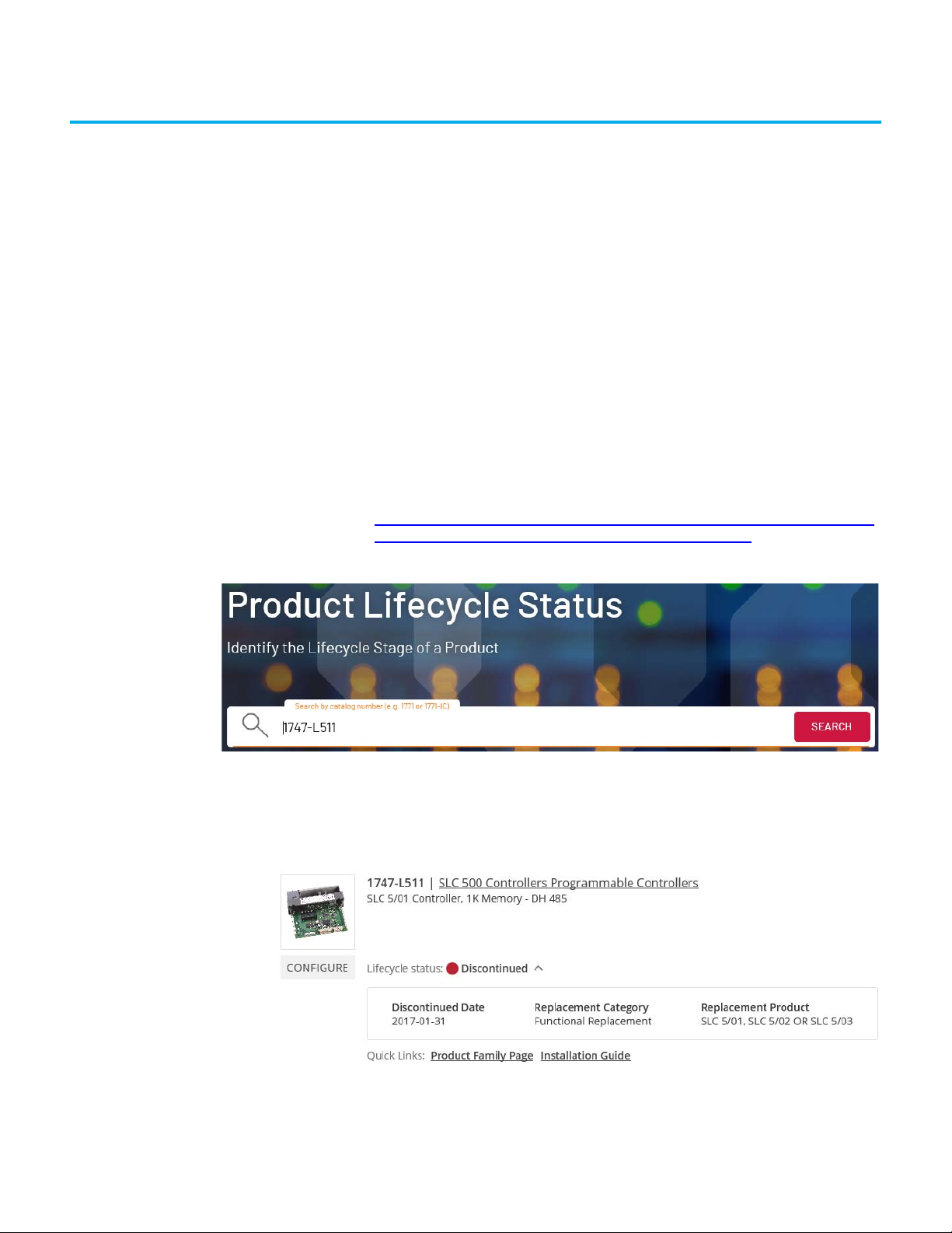
Product Lifecycle Status Website
The Rockwell Automation Product Lifecycle Status website allows you to proactively plan and manage the transition from existing equipment to leadingedge products and technologies. Using the search tool, you can view up-to-date
product lifecycle status and identify the most contemporary Rockwell
Automation products.
The product lifecycle status may be Active, Active Mature, End of Life, or
Discontinued.
To view the lifecycle information for a product:
1. On your web browser, open the Product Lifecycle Status website:
https://www.rockwellautomation.com/en-us/support/product/productcompatibility-migration/product-lifecycle-status.html.
2. In the Catalog Number field, enter the catalog number of the product.
3. Click Search.
The product lifecycle data displays.
If the lifecycle status of the product is End of Life or Discontinued, you
can view the recommended replacement.
Rockwell Automation Publication 1746-RM003E-EN-E - August 2020 9
Page 10

Chapter 1 Overview
SLC 500 System The SLC 500 system is a small chassis-based family of programmable
controllers, discrete, analog, and specialty I/O, and peripheral devices. The SLC
500 family delivers power and flexibility with a wide range of communication
configurations, features, and memory options.
SLC 500 programmable controllers provide value with extensive capabilities to
address a broad range of applications including material handling, HVAC
control, high-speed assembly operations, small process control, simple motion
control, and SCADA. With SLC 500 Modular Hardware Style controllers, you
select the processor, power supply, and I/O modules to fit your application.
Modular style chassis are available in 4, 7, 10, and 13-slot versions.
Digital I/O modules, analog I/O modules, and specialty temperature, counting,
and process control modules are available to help you create a custom solution
for your application.
CompactLogix 5370 Controllers
CompactLogix 5380 Controllers
CompactLogix 5370 controllers provide scalable controller solutions to address
a wide variety of applications. All CompactLogix 5370 controllers provide the
following functionality:
• Two EtherNet/IP™ ports
• One USB port
• Support for local expansion modules
• Control of local and distributed I/O modules
• Use of 1784-SD1 or 1784-SD2 Secure Digital (SD) card for nonvolatile
memory
• A battery is no longer necessary because of the internal energy-storage
solution
Some CompactLogix 5370 controllers provide the following functionality:
• Built-in power supply
• Some combination of embedded digital, analog, and high-speed counter
modules
• Support for Integrated Motion over an EtherNet/IP network
• Access to DeviceNet® networks.
CompactLogix 5380 controllers can operate in various applications that range
from standalone systems or in more complex systems with devices that are
connected to the controller via an EtherNet/IP network. All CompactLogix
5380 controllers provide the following functionality:
• Two EtherNet/IP ports
• One USB port
• Support for local expansion modules
• Control of local and distributed I/O modules
• Support Device Level Ring (DLR), Star, and Linear EtherNet/IP network
topologies.
• Support up to 180 EtherNet/IP nodes, depending on catalog number.
• Support Linear/DLR and Dual-IP EtherNet/IP modes.
10 Rockwell Automation Publication 1746-RM003E-EN-E - August 2020
Page 11

Chapter 1 Overview
• Support Generic ASCII, Modbus RTU/ASCII, and legacy DF1 and DH-485
protocols.
Some CompactLogix 5380 controllers provide the following functionality:
• Support for Integrated Motion up to 32 axes over an EtherNet/IP
network
Compact I/O Modules The Compact I/O modules can be used in the following applications:
• With a CompactLogix controller
• In an assembly with a 1769-ADN DeviceNet adapter
• In an assembly with a 1769-AENTR Ethernet adapter.
Each I/O module includes a built-in removable terminal block with fingersafe
cover for connections to I/O sensors and actuators. The terminal block is
behind a door at the front of the module. I/O wiring can be routed from
beneath the module to the I/O terminals.
• Once the modules are locked together, the system becomes a rugged
assembly.
• Upper and lower tongue-and-groove slots guide the module during
installation and secure the module within the system.
• Removable terminal blocks help ease the wiring task.
• Self-lifting, field-wire pressure plates cut installation time.
• The patented bus connector with the lock function enables consistent
system communication.
• A color bar is provided on the front of the module.
• Digital and field circuits are optically isolated.
Compact 5000 I/O Modules The Compact 5000 I/O architecture provides a wide range of input and output
modules to span many applications, from high-speed digital to process
control. The architecture uses Producer/Consumer technology that allows
input information and output status to be shared among multiple
Logix 5000 controllers.
Compact 5000 I/O systems are used as local I/O modules in
CompactLogix 5380 controller systems or as remote I/O modules with
CompactLogix 5380 controllers and some other Logix 5000 controllers. The
modules are configured with the Studio 5000 Logix Designer application.
The serial module provides two independent channels that function as
network interface using RS232C, RS422, or RS485 to serial devices
communicating on Generic ASCII, Modbus RTU/ASCII, DF1, or DH-485
protocol.
The I/O module requires a removable terminal block (RTB) to connect fieldside wiring. RTBs are not included with the I/O modules. You must order
RTBs separately.
Rockwell Automation Publication 1746-RM003E-EN-E - August 2020 11
Page 12
Chapter 1 Overview
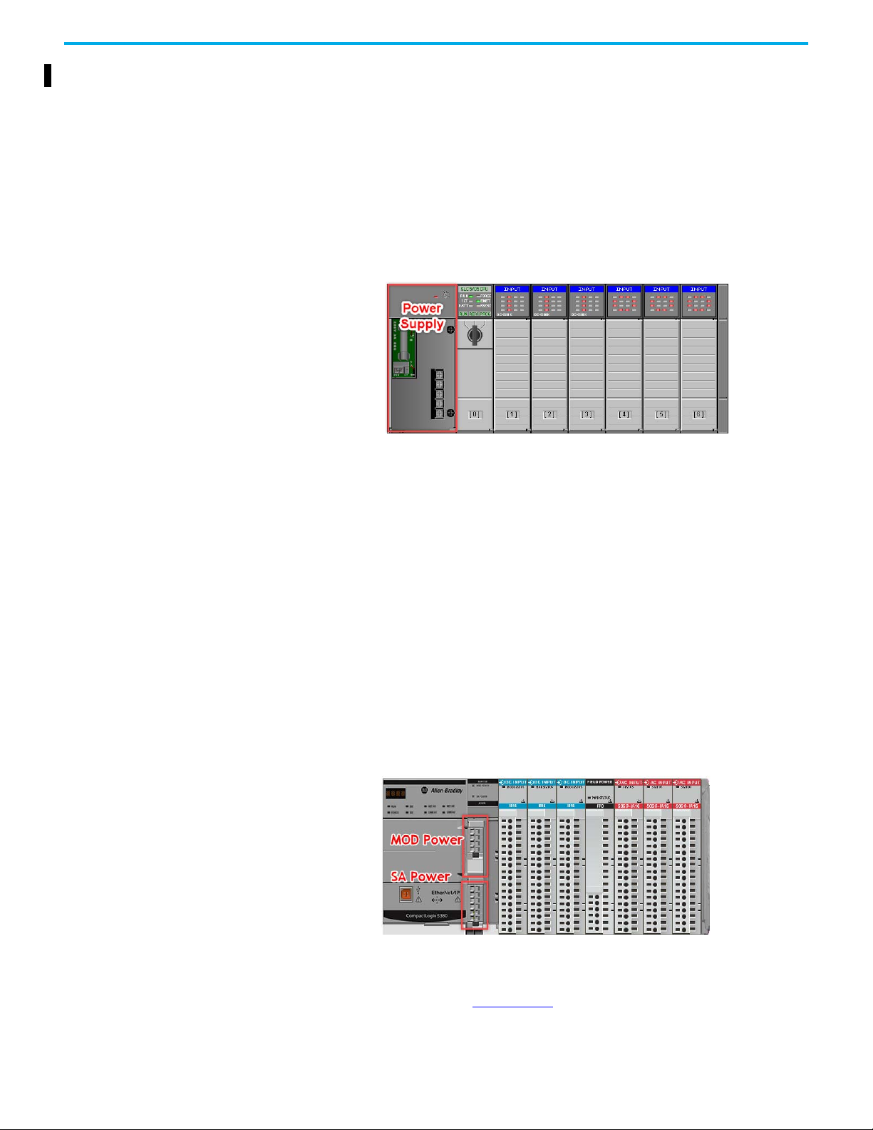
Power Considerations SLC 500 Controllers
The SLC 500 controllers require an SLC power supply module on the leftmost
slot to provide power to all modules on the chassis. This powers up the
controller and the I/O modules. This also facilitates communication through
the backplane.
Though all 1746 input modules and most 1746 output modules receive the
necessary power that they need from the backplane, some 1746 output
modules, such as relay modules and AC modules, require additional power to
be supplied to the module terminal block.
CompactLogix 5380 Controllers
The CompactLogix 5380 controllers require a 24V DC source supply that is
connected to the MOD power terminal to provide power to all modules. Unlike
the SLC 500 controller, the CompactLogix 5380 controller does not require
a chassis.
Backplane connection is at the side of each module and it is necessary to cover
the side with a 5069-ECR end cap (shipped with the CompactLogix 5380
controllers and Compact 5000 EtherNet/IP adapters) to help prevent
electrical hazards.
The 24V DC source to MOD power terminal can be from any external power
supply. You do not require additional power supply connections to each I/O
module
(1)
if connecting field devices are in the same operating voltage range.
For more information about MOD power and SA power considerations, see
chapter 2 of the CompactLogix 5380 and Compact GuardLogix® 5380
Controllers User Manual, 5069-UM001
(1) Except for 5069-OB8, 5069-OB16 and 5069-OB16F.
12 Rockwell Automation Publication 1746-RM003E-EN-E - August 2020
.
Page 13
Chapter 1 Overview
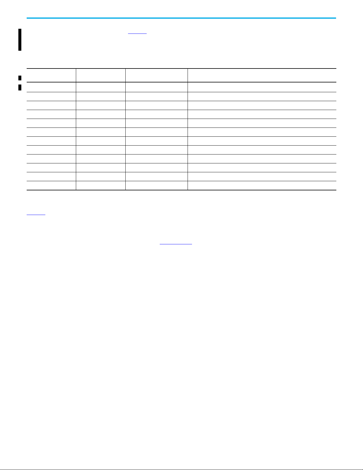
The CompactLogix 5380 I/O power system if sensors/actuators have a common operating voltage.
The CompactLogix 5380 I/O power system if sensors/actuators have different operating voltages.
Sensor Actuator Power for CompactLogix 5380
The CompactLogix 5380 I/O power system has a common sensor actuator (SA)
bus where a single power source can be shared among all attaching I/O
modules using the backplane. This helps reduce wiring effort and is
convenient if all I/O devices operate at the same operating voltage. If the SA
has two different operating voltages (see following figures), the SA power bus
can be separated with a Field Potential Distributor Module, such as the 5069FPD.
IMPORTANT
Rockwell Automation Publication 1746-RM003E-EN-E - August 2020 13
The 5069-OW16 module uses DC SA power. You must connect DC power
to the component, that is, controller, adapter, or field potential
distributor, that provides SA power to the module.
Page 14

Chapter 1 Overview
Other Considerations
The SLC 500 system was designed more than 30 years ago and electronic
components have evolved over time. To help avoid potential electromagnetic
interference (EMI) and transient EMI that could cause problems in your
existing system conversion, see the Industrial Automation Wiring and
Grounding Guidelines, publication 1770-IN041
.
To fully migrate your SLC 500 systems you also need to
convert your SLC 500
application code. For more information on software conversion, see the SLC to
CompactLogix Programming Migration Application Profile, publication
5069-AP001.
14 Rockwell Automation Publication 1746-RM003E-EN-E - August 2020
Page 15

Chapter 2
Replace an SLC 500 Controller
This chapter provides information about the recommended replacement for
your existing SLC 500 controller.
Due to the discontinuation of SLC 5/01 and SLC 5/02 controllers in
January 2017, a replacement CompactLogix controller is recommended.
You can view the lifecycle status of your SLC product on the Rockwell
Automation Product Lifecycle Status website:
https://www.rockwellautomation.com/en-us/support/product/productcompatibility-migration/product-lifecycle-status.html.
Upgrade to a CompactLogix 5370 Controller
Table 1 lists the recommended replacement CompactLogix 5370 controller to
your existing SLC 500 controller. These recommendations exclude Motion and
Safety applications, consult your local sales office for more info.
Table 1 - Recommended CompactLogix 5370 Replacement Controllers
Catalog Number
1747-L511 SLC 5/01 1K Controller 1769-L24ER-QB1B CompactLogix 5370 L2 Controller, 750 KB Memory, 16 DC Inputs, 16 DC Outputs
1747-L514 SLC 5/01 4K Controller 1769-L24ER-QB1B CompactLogix 5370 L2 Controller, 750 KB Memory, 16 DC Inputs, 16 DC Outputs
1747-L524 SLC 5/02 4K Controller 1769-L24ER-QB1B CompactLogix 5370 L2 Controller, 750 KB Memory, 16 DC Inputs, 16 DC Outputs
1747-L531 SLC™ 5/03 8K Controller 1769-L24ER-QB1B CompactLogix 5370 L2 Controller, 750 KB Memory, 16 DC Inputs, 16 DC Outputs
1747-L532 SLC 5/03 16K Controller 1769-L24ER-QB1B CompactLogix 5370 L2 Controller, 750 KB Memory, 16 DC Inputs, 16 DC Outputs
1747-L533 SLC 5/03 32K Controller 1769-L24ER-QB1B CompactLogix 5370 L2 Controller, 750 KB Memory, 16 DC Inputs, 16 DC Outputs
1747-L541 SLC 5/04 16K Controller 1769-L24ER-QB1B CompactLogix 5370 L2 Controller, 750 KB Memory, 16 DC Inputs, 16 DC Outputs
1747-L542 SLC 5/04 32K Controller 1769-L24ER-QB1B CompactLogix 5370 L2 Controller, 750 KB Memory, 16 DC Inputs, 16 DC Outputs
1747-L543 SLC 5/04 64K Controller 1769-L30ER CompactLogix 5370 L3 Controller, 1 MB Memory, Dual Ethernet Port - SD Card
1747-L551 SLC 5/05 16K Controller 1769-L24ER-QB1B CompactLogix 5370 L2 Controller, 750 KB Memory, 16 DC Inputs, 16 DC Outputs
1747-L552 SLC 5/05 32K Controller 1769-L24ER-QB1B CompactLogix 5370 L2 Controller, 750 KB Memory, 16 DC Inputs, 16 DC Outputs
1747-L553 SLC 5/05 64K Controller 1769-L30ER CompactLogix 5370 L3 Controller, 1 MB Memory, Dual Ethernet Port - SD Card
(1) The general rule
5069-AP001.
Alternatively, you may validate the controller based on memory estimation by the code conversion tool (RSLogix Project Migrator).
SLC Controller
Description
of thumb for memory estimation can be found under “SLC to Logix Memory Comparison” in the SLC to CompactLogix Programming Migration Application Profile, publication
Recommended CompactLogix
5370 Controller Replacement
CompactLogix 5370 Controller Description
(1)
For technical specifications of the recommended CompactLogix 5370
controller, see CompactLogix Controllers Specifications Technical Data,
publication 1769-TD005
Rockwell Automation Publication 1746-RM003E-EN-E - August 2020 15
.
Page 16
Chapter 2 Replace an SLC 500 Controller
Upgrade to a CompactLogix 5380 Controller
Table 2 lists the recommended replacement CompactLogix 5380 controller to
your existing SLC 500 controller. These recommendations exclude Motion
applications, consult your local sales office for more information.
Table 2 - Recommended CompactLogix 5380 Replacement Controllers
Catalog Number
1747-L511 SLC 5/01 1K Controller
1747-L514 SLC 5/01 4K Controller 5069-L306ER CompactLogix 5380 Controller, 600 KB, 8 I/O, 16 nodes, Standard
1747-L524 SLC 5/02 4K Controller 5069-L306ER CompactLogix 5380 Controller, 600 KB, 8 I/O, 16 nodes, Standard
1747-L531 SLC 5/03 8K Controller 5069-L306ER CompactLogix 5380 Controller, 600 KB, 8 I/O, 16 nodes, Standard
1747-L532 SLC 5/03 16K Controller 5069-L306ER CompactLogix 5380 Controller, 600 KB, 8 I/O, 16 nodes, Standard
1747-L533 SLC 5/03 32K Controller 5069-L306ER CompactLogix 5380 Controller, 600 KB, 8 I/O, 16 nodes, Standard
1747-L541 SLC 5/04 16K Controller 5069-L306ER CompactLogix 5380 Controller, 600 KB, 8 I/O, 16 nodes, Standard
1747-L542 SLC 5/04 32K Controller 5069-L306ER CompactLogix 5380 Controller, 600 KB, 8 I/O, 16 nodes, Standard
1747-L543 SLC 5/04 64K Controller 5069-L310ER CompactLogix 5380 Controller, 1 MB, 8 I/O, 24 nodes, Standard
1747-L551 SLC 5/05 16K Controller 5069-L306ER CompactLogix 5380 Controller, 600 KB, 8 I/O, 16 nodes, Standard
1747-L552 SLC 5/05 32K Controller 5069-L306ER CompactLogix 5380 Controller, 600 KB, 8 I/O, 16 nodes, Standard
1747-L553 SLC 5/05 64K Controller 5069-L310ER CompactLogix 5380 Controller, 1 MB, 8 I/O, 24 nodes, Standard
(1) To include safety on the control, you can upgrade any recommended CompactLogix 5380 replacement controller to Compact GuardLogix 5380 SIL 2 and Compact GuardLogix 5380 SIL 3
safety controllers.
(2) The general rule of thumb for memory estimation can be found under “SLC to Logix Mem
5069-AP001.
Alternatively, you can validate the controller based on memory estimation by the code conversion tool (RSLogix™ Project Migrator).
SLC Controller
Description
Recommended CompactLogix
5380 Controller Replacement
5069-L306ER
(1)(2)
CompactLogix 5380 Controller Description
CompactLogix 5380 Controller, 600 KB, 8 I/O, 16 nodes, Standard
ory Comparison” in the SLC to CompactLogix Programming Migration Application Profile, publication
For technical specifications of the recommended CompactLogix 5380
controller, see CompactLogix Controllers Specifications Technical Data,
publication 5069-TD002
.
16 Rockwell Automation Publication 1746-RM003E-EN-E - August 2020
Page 17
Chapter 3
Replace an SLC 500 I/O Module
This chapter provides information about the recommended replacement for
your existing SLC 500 I/O module.
The lifecycle status for Rockwell Automation products is maintained and
published in the Rockwell Automation Product Lifecycle Status website:
https://www.rockwellautomation.com/en-us/support/product/productcompatibility-migration/product-lifecycle-status.html.
Upgrade an SLC I/O Installation by Replacing it with Compact I/O
Table 3 lists the recommended replacement Compact I/O module to your
existing SLC 500 I/O module.
Before upgrading, take note of the following:
• When replacing an SLC I/O with a Compact I/O, a CompactLogix 5370
• There might be technical differences between the SLC I/O and
Table 3 - Recommended Compact I/O Replacement
Module Type
Digital input
Catalog Number
1746-IA4 100/120V AC 4 120V AC input module 1769-IA8I 8 inputs, individually isolated, 100/120V AC input module
1746-IA8 100/120V AC 8 120V AC input module 1769-IA8I 8 inputs, individually isolated, 100/120V AC input module
1746-IA16 100/120V AC 16 120V AC input module 1769-IA16 16 inputs, 100/120V AC input module
1746-IB8 24V DC 8 current sinking DC input module 1769-IQ16 16 inputs, 24V DC sink/souce input module
1746-IB16 24V DC 16 current sinking DC input module 1769-IQ16 16 inputs, 24V DC sink/souce input module
1746-IB32 24V DC 32 current sinking DC input module 1769-IQ32 32 inputs, 24V DC sink/souce input module
1746-IC16 48V DC 16 current sinking DC input module No replacement —
1746-IG16 5V DC 16 current sourcing TTL input module 1769-IG16 16 inputs, 5V DC TTL input module
1746-IH16 125V DC 16 current sinking DC input module No replacement —
1746-IM4 200/240V AC 4 240V AC input module 1769-IM12 12 inputs, 200/240V AC input module
1746-IM8 200/240V AC 8 240V AC input module 1769-IM12 12 inputs, 200/240V AC input module
1746-IM16 200/240V AC 16 240V AC input module 1769-IM12 12 inputs, 200/240V AC input module
1746-IN16 24V AC/DC 16 24V AC/DC input module No replacement —
1746-ITB16 24V DC 16 fast response DC sinking input module 1769-IQ16F 16 inputs, high-speed 24V DC sink/source digital input module
(1)
SLC Module Description
controller must be used.
Compact I/O. Verify the specifications to meet your application needs.
For wiring diagrams and technical specifications of Compact I/O
modules, see Compact I/O Modules Specifications Technical Data,
publication 1769-TD006
.
Recommended
Compact I/O
Replacement
Compact I/O Module Description
(2)
Rockwell Automation Publication 1746-RM003E-EN-E - August 2020 17
Page 18

Chapter 3 Replace an SLC 500 I/O Module
Table 3 - Recommended Compact I/O Replacement (Continued)
Module Type
Digital input
Digital output
Digital
combination
Catalog Number
1746-ITV16 24V DC 16 fast response DC sourcing input module 1769-IQ16F 16 inputs, high-speed 24V DC sink/source digital input module
1746-IV8 24V DC 8 current sourcing DC input module 1769-IQ16 16 inputs, 24V DC sink/source input module
1746-IV16 24V DC 16 current sourcing DC input module 1769-IQ16 16 inputs, 24V DC sink/source input module
1746-IV32 24V DC 32 current sourcing DC input module 1769-IQ32 32 inputs, 24V DC sink/source input module
1746-OA8 120/240V AC 8 120/240V AC output module 1769-OA8 8 outputs, 100/240V AC input module
1746-OA16 120/240V AC 16 120/240V AC output module 1769-OA16 16 outputs, 100/240V AC input module
1746-OAP12 120/240V AC 12 high current 120/240V AC output module No replacement —
1746-OB6EI
1746-OB8 24V DC 8 current sourcing DC output module 1769-OB8 8 outputs, 24V DC source output module
1746-OB16 24V DC 16 current sourcing DC output module 1769-OB16 16 outputs, 24V DC source output module
1746-OB16E
1746-OB32 24V DC 32 current sourcing DC output module 1769-OB32 32 outputs, 24V DC source output module
1746-OB32E
1746-OBP8 24V DC 8 high current sourcing DC output module 1769-OB8 8 outputs, 24V DC source output module
1746-OBP16 24V DC 16 high current sourcing DC output module No replacement —
1746-OG16 5V DC 16 current sourcing TTL output module 1769-OG16 16 outputs, 5V DC TTL output module
1746-OV8 24V DC 8 current sinking DC output module 1769-OV16 16 outputs, 24V DC sink output module
1746-OV16 24V DC 16 current sinking DC output module 1769-OV16 16 output, 24V DC sink output module
1746-OV32 24V DC 32 current sinking DC output module 1769-OV32T 32 terminated outputs, 24V DC sink output module
1746-OVP16 24V DC 16 high current sinking DC output module No replacement —
1746-OW4 AC/DC relay 4 relay (hard contact) output module 1769-OW8 8 outputs, 5...265V AC/5...125V DC relay output module
1746-OW8 AC/DC relay 8 relay (hard contact) output module 1769-OW8 8 outputs, 5...265V AC/5...125V DC relay output module
1746-OW16 AC/DC relay 16 relay (hard contact) output module 1769-OW16 16 outputs, 5...265V AC/5...125V DC relay output module
1746-OX8 AC/DC relay 8 relay (hard contact) output module No replacement —
1746-IO4
1746-IO8
1746-IO12
1746-IO12DC
(1)
SLC Module Description
24V DC 6 electronically protected isolated sourcing DC
output module
24V DC 16 electronically protected current sourcing DC
output module
24V DC 32 electronically protected current sourcing DC
output module
120V AC (inputs) 100/120V AC (relay contact outputs) 2-in
2-out combination input/output module
120V AC (inputs) 100/120V AC (relay contact outputs) 4-in
4-out combination input/output module
120V AC (inputs) 100/120V AC (relay contact outputs) 6-in
6-out combination input/output module
240V DC (inputs) 100/120V AC (relay contact outputs) 6-in
6-out combination input/output module
Recommended
Compact I/O
Replacement
No replacement —
1769-OB16P 16 outputs, protected, 24V DC source output module
No replacement —
No replacement —
No replacement —
No replacement —
1769-IQ6XOW4
Compact I/O Module Description
(2)
6 inputs, 4 outputs, 24V DC sink/source input AC/DC
normally open, relay contact output module
18 Rockwell Automation Publication 1746-RM003E-EN-E - August 2020
Page 19

Table 3 - Recommended Compact I/O Replacement (Continued)
Module Type
Analog input
Analog output
Analog
combination
Catalog Number
1746-INT4
1746-NI4 High resolution (4) analog input module 1769-IF4
1746-NI8 High resolution (8) analog input module 1769-IF8
1746-NI16I -20 mA to +20 mA high resolution (16) analog input module 1769-IF16C
1746-NI16V
1746-NR4 4-channel RTD/resistance input module 1769-IR6
1746-NR8 8-channel RTD/resistance input module 1769-IR6
1746-NT4
1746-NT8
1746-NIO4I
1746-NIO4V
1746-NO4I 0...20 mA (4) analog current output module 1769-OF4
1746-NO4V -10V DC to +10V DC (4) analog current output module 1769-OF4
1746-NO8I 0...20 mA (8) analog current output module 1769-OF8C
1746-NO8V -10V DC to +10V DC (8) analog current output module 1769-OF8V
1746-FIO4I (2) Fast analog input, (2) analog current output module 1769-IF4XOF2
1746-FIO4V (2) Fast analog input, (2) analog voltage output module 1769-IF4XOF2
(1)
SLC Module Description
4-channel thermocouple (J, K, T, E, R, S, B, N, C, D)/mV
input module
-10V DC to +10V DC high resolution (16) analog input
module
4-channel thermocouple (J, K, T, E, R, S, B, N)/mV
input module
8-channel thermocouple (J, K, T, E, R, S, B, N)/mV
input module
High resolution (2) analog input, (2) analog current
output module
High resolution (2) analog input, (2) analog voltage
output module
Chapter 3 Replace an SLC 500 I/O Module
Recommended
Compact I/O
Replacement
1769sc-IT6I Isolated thermocouple or millivolt input module
1769-IF16V
1769-IT6
1769-IT6
1769-IF4XOF2
1769-IF4XOF2
Compact I/O Module Description
(2)
4 inputs, differential or single-ended, ±10V/0...10V/0...5V/1...5V/
0...20 mA/4...20 mA analog input module
8 inputs, differential or single-ended, ±10V/0...10V/0...5V/1...5V/
0...20 mA/4...20 mA analog input module
16 inputs, single-ended 0...20 mA/ 4...20 mA analog
input module
16 inputs, single-ended, ±10V/0...10V/0...5V/1...5V analog
input module
6 RTD inputs, 100, 200, 500, 1000 Platinum 385/3916, 120 ohm
Nickel 618/672, 10 ohm Nickel-iron, 0...150/500/1000/3000 ohm
module
6 RTD inputs, 100, 200, 500, 1000 Platinum 385/3916, 120 ohm
Nickel 618/672, 10 ohm Nickel-iron, 0...150/500/1000/3000 ohm
module
6 thermocouple, thermocouple types B, C, E, J, K, N, R, S, T/
±50V/±100V module
6 thermocouple, thermocouple types B, C, E, J, K, N, R, S, T/
±50V/±100V module
4 inputs, differential or single-ended, 2 outputs, single-ended
analog module
4 inputs, differential or single-ended, 2 outputs, single-ended
analog module
4 outputs, single-ended, ±10V/0...10V/0...5V/1...5V/0...20 mA/
4...20 mA analog output module
4 outputs, single-ended, ±10V/0...10V/0...5V/1...5V/0...20 mA/
4...20 mA analog output module
8 outputs, single-ended, 0...20 mA/4...20 mA analog
output module
8 outputs, single-ended, ±10V/0...10V/0...5V/1...5V analog
output module
4 inputs, differential or single-ended, 2 outputs, single-ended
analog module
4 inputs, differential or single-ended, 2 outputs, single-ended
analog module
Rockwell Automation Publication 1746-RM003E-EN-E - August 2020 19
Page 20

Chapter 3 Replace an SLC 500 I/O Module
Table 3 - Recommended Compact I/O Replacement (Continued)
Module Type
Specialty 1747-ACN15 ControlNet® adapter No replacement —
(1) The product may be in Active Mature, End of Life, or Discontinued state. To view the most up-to-date product lifecycle status, search for the catalog number on the Product Lifecycle Status
website.
(2) The recommended replacements that are indicated in this table are for reference only. There may be slight differences in specifications between the existing 1746 SLC I/O module and
recommended 1769 Compact I/O module. Consult your local sales team for further assistance.
Catalog Number
1747-ACNR15 ControlNet adapter, redundant No replacement —
1747-ASB SLC 500 remote I/O adapter No replacement —
1746-BAS B asic module No replacement —
1746-BAS-T High-s peed basic module No replacement —
1746-BLM Blow molding module No replacement —
1746-BTM Barrel temperature module No replacement —
1746-HS IMC 110 motion module No replacement —
1746-HSCE High-speed counter encoder module No replacement —
1746-HSCE2 Multi-channel high-speed counter encoder module 1769-HSC High-speed counter module
1746-HSTP1 1-axis stepper module No replacement —
1746-N2 Empty slot filler 1769-ARM Compact address reserve module
1746-QS Synchronized axis module No replacement —
1746-QV Open loop velocity control module No replacement —
1747-SCNR ControlNet scanner No replacement —
1747-SDN DeviceNet scanner 1769-SDN Compact I/O DeviceNet scanner
1746-SIM 16-point input simulator modul e No replacement —
1747-SN Remote I/O scanner No replacement —
(1)
SLC Module Description
Recommended
Compact I/O
Replacement
Compact I/O Module Description
(2)
Upgrade an SLC I/O Installation by Replacing it with Compact 5000 I/O
Table 4 lists the recommended replacement Compact 5000 I/O module to your
existing SLC 500 I/O module.
Before upgrading, take note of the following:
• When replacing an SLC I/O with a Compact 5000 I/O, a
CompactLogix 5380, CompactLogix 5480, or ControlLogix® 5580
controller must be used.
• There might be technical differences between the SLC I/O and
Compact 5000 I/O. Verify the specifications to meet your application
needs. For wiring diagrams and technical specifications of Compact
5000 I/O modules, see Compact 5000 I/O Modules Specifications
Technical Data, publication 5069-TD001
.
20 Rockwell Automation Publication 1746-RM003E-EN-E - August 2020
Page 21

Table 4 - Recommended Compact 5000 I/O Replacement
Chapter 3 Replace an SLC 500 I/O Module
Module Type
Digital input
Digital output
Digital output
(cont)
Recommended
Compact 5000 I/O
Replacement
(2)
Compact 5000 I/O Module Description
Catalog Number
(1)
SLC Module Description
1746-IA4 100/120V AC 4 120V AC input module 5069-IA16 16-point, 120/240V AC digital input module
1746-IA8 100/120V AC 8 120V AC input module 5069-IA16 16-point, 120/240V AC digital input module
1746-IA16 100/120V AC 16 120V AC input module 5069-IA16 16-point, 120/240V AC digital input module
1746-IB8 24V DC 8 current sinking DC input module 5069-IB16 16-point, 24V DC sinking digital input module
1746-IB16 24V DC 16 current sinking DC input module 5069-IB16 16-point, 24V DC sinking digital input module
1746-IB32 24V DC 32 current sinking DC input module
5069-IB16 x 2
(3)
16-point, 24V DC sinking digital input module
1746-IC16 48V DC 16 current sinking DC input module No replacement —
1746-IG16 5V DC 16 current sourcing TTL input module No replacement —
1746-IH16 125V DC 16 current sinking DC input module No replacement —
1746-IM4 200/240V AC 4 240V AC input module 5069-IA16 16-point, 120/240V AC digital input module
1746-IM8 200/240V AC 8 240V AC input module 5069-IA16 16-point, 120/240V AC digital input module
1746-IM16 200/240V AC 16 240V AC input module 5069-IA16 16-point, 120/240V AC digital input module
1746-IN16 24V AC/DC 16 24V AC/DC input module No replacement —
1746-ITB16 24V DC 16 fast response DC sinking input module 5069-IB16 16-point, 24V DC sinking digital input module
1746-ITV16 24V DC 16 fast response DC sourcing input module No replacement —
1746-IV8 24V DC 8 current sourcing DC input module No replacement —
1746-IV16 24V DC 16 current sourcing DC input module No replacement —
1746-IV32 24V DC 32 current sourcing DC input module No replacement —
1746-OA8 120/240V AC 8 120/240V AC output module 5069-OA16 16-point, 120/240V AC digital output module
1746-OA16 120/240V AC 16 120/240V AC output module 5069-OA16 16-point, 120/240V AC digital output module
1746-OAP12 120/240V AC 12 high current 120/240V AC output module No replacement —
1746-OB6EI
24V DC 6 electronically protected isolated sourcing DC
output module
No replacement —
1746-OB8 24V DC 8 current sourcing DC output module 5069-OB8 8-point, 24V DC high current digital output module
1746-OB16 24V DC 16 current sourcing DC output module 5069-OB16 16-point, 24V DC sourcing digital output module
1746-OB16E
24V DC 16 electronically protected current sourcing DC
output module
1746-OB32 24V DC 32 current sourcing DC output module
1746-OB32E
24V DC 32 electronically protected current sourcing DC
output module
5069-OB16 16-point, 24V DC sourcing digital output module
(3)
5069-OB16 x 2
5069-OB16 x 2
16-point, 24V DC sourcing digital output module
(3)
16-point, 24V DC sourcing digital output module
1746-OBP8 24V DC 8 high current sourcing DC output module 5069-OB8 8-point, 24V DC high current digital output module
(4)
1746-OBP16 24V DC 16 high current sourcing DC output module
5069-OB8 x 2
16-point, 24V DC high current digital output module
1746-OG16 5V DC 16 current sourcing TTL output module No replacement —
1746-OV8 24V DC 8 current sinking DC output module No replacement —
1746-OV16 24V DC 16 current sinking DC output module No replacement —
1746-OV32 24V DC 32 current sinking DC output module No replacement —
1746-OVP16 24V DC 16 high current sinking DC output module No replacement —
1746-OW4 AC/DC relay 4 relay (hard contact) output module
1746-OW8 AC/DC relay 8 relay (hard contact) output module
1746-OW16 AC/DC relay 16 relay (hard contact) output module
1746-OX8 AC/DC relay 8 relay (hard contact) output module
5069-OW4I
5069-OW16
5069-OW16
5069-OX4I
(5)(6)
(5)(6)
(5)(6)
(5)(6)
4-point, normally open, isolated relay output module
16-point, non-isolated, high-density relay output module
16-point, non-isolated, high-density relay output module
4-point, normally open/normally closed, isolated relay
output module
Rockwell Automation Publication 1746-RM003E-EN-E - August 2020 21
Page 22

Chapter 3 Replace an SLC 500 I/O Module
Table 4 - Recommended Compact 5000 I/O Replacement (Continued)
Module Type
Digital
combination
Analog input
Analog output
Analog
combination
Specialty
(1)
Catalog Number
1746-IO4
1746-IO8
1746-IO12
1746-IO12DC
1746-INT4
1746-NI4 High resolution (4) analog input module 5069-IY4
1746-NI8 High resolution (8) analog input module 5069-IF8 8-channel, analog input module, differential inputs only
1746-NI16I -20 mA to +20 mA high resolution (16) analog input module 5069-IF8 8-channel, analog input module, differential inputs only
1746-NI16V -10V DC to +10V DC high resolution (16) analog input module 5069-IF8 8-channel, analog input module, differential inputs only
1746-NR4 4-channel RTD/resistance input module 5069-IY4
1746-NR8 8-channel RTD/resistance input module 5069-IY4
1746-NT4
1746-NT8
1746-NIO4I
1746-NIO4V
1746-NO4I 0...20 mA (4) analog current output module 5069-OF4 4-channel, analog output module
1746-NO4V -10V DC to +10V DC (4) analog current output module 5069-OF4 4-channel, analog output module
1746-NO8I 0...20 mA (8) analog current output module 5069-OF8 8-channel, analog output module
1746-NO8V -10V DC to +10V DC (8) analog current output module 5069-OF8 8-channel, analog output module
1746-FIO4I (2) Fast analog input, (2) analog current output module No replacement —
1746-FIO4V (2) Fast analog input, (2) analog voltage output module No replacement —
1747-ACN15 ControlNet adapter No replacement —
1747-ACNR15 ControlNet adapter, redundant No replacement —
1747-ASB SLC 500 remote I/O adapter No replacement —
1746-BAS Basic module No replacement —
1746-BAS-T High-speed basic module No replacement —
1746-BLM Blow molding module No replacement —
1746-BTM Barrel temperature module No replacement —
SLC Module Description
120V AC (inputs) 100/120V AC (relay contact outputs) 2-in
2-out combination input/output module
120V AC (inputs) 100/120V AC (relay contact outputs) 4-in
4-out combination input/output module
120V AC (inputs) 100/120V AC (relay contact outputs) 6-in
6-out combination input/output module
240V DC (inputs) 100/120V AC (relay contact outputs) 6-in
6-out combination input/output module
4-channel thermocouple (J, K, T, E, R, S, B, N, C, D)/mV
input module
4-channel thermocouple (J, K, T, E, R, S, B, N)/mV
input module
8-channel thermocouple (J, K, T, E, R, S, B, N)/mV
input module
High resolution (2) analog input, (2) analog current
output module
High resolution (2) analog input, (2) analog voltage
output module
Recommended
Compact 5000 I/O
Replacement
No replacement —
No replacement —
No replacement —
No replacement —
No replacement —
5069-IY4
5069-IY4
No replacement —
No replacement —
(2)
Compact 5000 I/O Module Description
4-channel, universal analog input module, differential
inputs only
4-channel, universal analog input module, differential
inputs only
4-channel, universal analog input module, differential
inputs only
4-channel, universal analog input module, differential
inputs only
4-channel, universal analog input module, differential
inputs only
22 Rockwell Automation Publication 1746-RM003E-EN-E - August 2020
Page 23

Table 4 - Recommended Compact 5000 I/O Replacement (Continued)
Chapter 3 Replace an SLC 500 I/O Module
Module Type
Specialty
(cont)
(1) The product may be in Active Mature, End of Life, or Discontinued state. To view the most up-to-date product lifecycle status, search for the catalog number on the Product Lifecycle Status
website.
(2) The recommended replacements that are indicated in this table are for reference only. There may be slight differences in specifications between the existing 1746 SLC I/O module and
recommended 5069 Compact 5000 I/O module. Consult your local sales team for further assistance.
(3) 1746-IB32 modules can be replaced with two 5069-IB16 modules.
(4) 1746-OBP16 modules can be replaced with two 5069-OB8 modules.
(5) 5069-OW16 is a DC module.
(6) The 5069-OW16 does not come with an internal snubber, an external surge suppressor is required. For more information on selecting and adding surge suppressors, see the Industrial
Automation Wiring and Grounding Guidelines, publication 1770-4.1
Catalog Number
1746-HS IMC 110 motion module No replacement —
1746-HSCE High-speed counter encoder module 5069-HSC2XOB4
1746-HSCE2 Multi-channel high-speed counter encoder module 5069-HSC2XOB4
1746-HSTP1 1 axis stepper module No replacement —
1746-N2 Empty slot filler 5069-ARM Address reserve module
1746-QS Synchronized axis module No replacement —
1746-QV Open loop velocity control module No replacement —
1747-SCNR ControlNet scanner No replacement —
1747-SDN DeviceNet scanner No replacement —
1746-SIM 16-point input simulator module No replacement —
1747-SN Remote I/O scanner No replacement —
(1)
SLC Module Description
.
Recommended
Compact 5000 I/O
Replacement
(2)
Compact 5000 I/O Module Description
High-speed counter, 2-axis, 4-point sourcing digital
output module
High-speed counter, 2-axis, 4-point sourcing digital
output module
SLC I/O Installation Using a Conversion Kit
You can use a conversion system to connect the existing SLC I/O wiring to the
Compact 5000 I/O modules without disturbing the field wiring connections,
reducing labor time and eliminating downtime that could result from wiring
mistakes during the migration. With a conversion system I/O can be swapped
one rack at a time, giving you the option to run both new and old I/O networks
simultaneously.
Table 5 - SLC I/O to Compact 5000 I/O Conversion System Selection
SLC I/O Module Catalog Number
(To be converted)
1746-IA16
1746-IM16 240VAC Input Module
1746-IB16
1746-ITB16 Fast Response DC Sinking Input Module
1746-OA16 5069-OA16 1492-CM1746-M02 120/240V AC Output Module
1746-OB16
1746-OB16E Current Sourcing DC Output Module
1746-OW16 5069-OW16 1492-CM1746-M04 AC/DC Relay Output Module
1746-NI8 5069-IF8 1492-CM1746-M05 High Resolution (8) Analog Input Module
1746-NI4
1746-NR4 1492-CM1746-M07 SLC 500 RTD/Resistance Input Module
1746-NT4 1492-CM1746-M09 4-Channel Thermocouple/mV Input Module
1746-NO4I
1746-NO4V 4 Point Analog Output Module (Voltage)
Compact 5000 I/O Modules
Catalog Number (To be
used)
Conversion Module Catalog
Number
5069-IA16
1492-CM1746-M01
5069-IB16
5069-OB16 1492-CM1746-M03
1492-CM1746-M06 High Resolution (4) Analog Input Module
5069-IY4
5069-OF4 1492-CM1746-M10
Conversion Module Description
120VAC Input Module
Current Sinking DC Input Module
Current Sourcing DC Output Module
4 Point Analog Output Module (Current)
Rockwell Automation Publication 1746-RM003E-EN-E - August 2020 23
Page 24

Chapter 3 Replace an SLC 500 I/O Module
Table 5 - SLC I/O to Compact 5000 I/O Conversion System Selection
SLC I/O Module Catalog Number
(To be converted)
1746-NO8I
1746-NO8V 8 Point Analog Output Module (Voltage)
1746-IB32 5069-IB16 (2x) 1492-CM1746-M12 Current Sinking DC Input Module
1746-OB32
1746-OB32E Current Sourcing DC Output Module
Compact 5000 I/O Modules
Catalog Number (To be
used)
5069-OF8 1492-CM1746-M11
5069-OB16 (2x) 1492-CM1746-M13
Conversion Module Catalog
Number
Conversion Module Description
8 Point Analog Output Module (Current)
Current Sourcing DC Output Module
Table 6 - SLC to Compact 5000 Chassis Conversion System Selection
SLC 500 Chassis 1492 Conversion Chassis 1792 Slots max Chassis Length Usable Length
1746-A4 1492-CH1746-4 4 235 mm (9.25 in.) 203 mm (8.00 in.) 4
1746-A7 1492-CH1746-7 7 339 mm (13.33 in.) 307 mm (12.08 in.) 9
1746-A10 1492-CH1746-10 10 454 mm (17.88 in.) 422 mm (16.63 in.) 14
1746-A13 1492-CH1746-13 13 559 mm (22.00 in.) 527 mm (20.75 in.) 19
For more information on choosing the appropriate conversion chassis and
conversion system for your system, see 1746 SLC I/O to Compact 5000 I/O
Conversion System Selection Guide, publication 1492-SG010
For more information on installing the 1492 conversion system chassis, see
1746-to-5069 I/O Conversion System Instruction Sheet, publication 1492-IN132
Number of Compact 5000
I/O Cards max
.
.
24 Rockwell Automation Publication 1746-RM003E-EN-E - August 2020
Page 25

Appendix A
RUN
FLT
BATT
FORCE
RUN REM PROG
DH485
SLC 5/03 CPU
RS232
9-pin female 25-pin 9-pin
DCD.IN 1 8 1
RXD.IN 2 3 2
TXD.OUT 3 2 3
DTR.OUT 4 20 4
SIG.GND 5 7 5
DSR.IN 6 6 6
RTS.OUT 7 4 7
CTS.IN 8 5 8
SLC 5/03, 5/04, 5/05
Serial Port
5069-SERIAL
Serial Module
Wiring Diagram Comparisons
This appendix provides wiring diagram comparisons of the recommended
replacement for your existing SLC 500 I/O module.
Replace an SLC 5 Processor Serial Port with a Compact I/O Serial Module
See the installations instructions and technical data of the associated catalogs
for the detailed wiring instruct
ions.
SLC 5/03, SLC 5/04, or SCL 5/05 to 5069-SERIAL
6
7
8
9
RS-232C
Pin
1 Data Carrier Detect (DCD) (i)
2 Receive Data (RXD) (i) A
3 Transmit Data (TXD) (o)
Data Terminal Ready
4
(DTR)
5 Common (COM) 6 Data Set Ready (DSR) (i) - 7 Request To Send (RTS) (o)
8 Clear To Send (CTS) (i) - A
9 - ---
Input (i)/Output (o)
(o) B
Wiring
No Handshaking Handshaking
1
2
3
4
5
--
A
A
A
B
A
B
A
A
Rockwell Automation Publication 1746-RM003E-EN-E - August 2020 25
Page 26

Appendix A Wiring Diagram Comparisons
AC
COM 0
IN 0
AC
COM 1
AC
COM 2
IN 1
IN 2
AC
COM 3
AC
COM 4
AC
COM 5
AC
COM 6
AC
COM 7
NC
NC
IN 3
IN 4
IN 5
IN 6
IN 7
100/120V AC
100/120V AC
100/120V AC
L1a
L2a
L1b
L2b
L1c
L2c
1769-IA8I
100/120V AC Input Module
AC
COM 0
IN 0
AC
COM 1
AC
COM 2
IN 1
IN 2
AC
COM 3
AC
COM 4
AC
COM 5
AC
COM 6
AC
COM 7
NC
NC
IN 3
IN 4
IN 5
IN 6
IN 7
100/120V AC
100/120V AC
100/120V AC
L1a
L2a
L1b
L2b
L1c
L2c
1769-IA8I
100/120V AC Input Module
Replace an SLC 500 I/O with a Compact I/O
100/120V AC
L1
100/120V AC
L2
See the installations instructions and technical data of the associated catalogs
for the detailed wiring instruct
ions.
1746-IA4 to 1769-IA8I
1746-IA4
NOT
USED
NOT
USED
NOT
USED
NOT
USED
IN 0
IN 1
IN 2
IN 3
AC COM
1746-IA8 to 1769-IA8I
1746-IA8
100/120V AC
L1
100/120V AC
L2
Internally Connected
Commons
IN 0
IN 1
IN 2
IN 3
IN 4
IN 5
IN 6
IN 7
AC COM
AC COM
26 Rockwell Automation Publication 1746-RM003E-EN-E - August 2020
Page 27

1746-IA16 to 1769-IA16
PLC
SLC
IN 1
IN 0
IN 2
IN 3
IN 4
IN 5
IN 6
IN 7
IN 9
IN 10
IN 11
IN 12
IN 13
IN 14
IN 15
AC COM
AC COM
0
1
2
4
6
IN 8
10
12
14
16
11
13
15
17
3
5
7
L1
L2
100/120V AC
1746-IA16
100/120V AC
Internally Connected
Commons
1769-IA16
100/120V AC Input Module
1769-IQ16
24V DC Sink/Source Input Module
L1
L2
100/120V AC
Appendix A Wiring Diagram Comparisons
IN 0
IN 1
IN 2
IN 3
IN 4
IN 5
IN 6
IN 7
IN 8
IN 9
IN 10
IN 11
IN 12
IN 13
IN 14
IN 15
AC
COM
COM
AC
Commons are
connected internally.
+DC
-DC
1746-IB8
24V DC Sinking
24V DC
Internally Connected
Commons
1746-IB8 to 1769-IQ16
+DC (sinking)
-DC (sourcing)
IN 0
IN 1
IN 2
IN 3
IN 4
IN 5
IN 6
IN 7
DC COM
DC COM
+DC (sinking)
-DC (sourcing)
24V DC
+DC (sinking)
-DC (sourcing)
Rockwell Automation Publication 1746-RM003E-EN-E - August 2020 27
IN 1
IN 3
IN 5
IN 7
IN 9
IN 11
IN 13
IN 15
DC
COM 2
IN 0
IN 2
IN 4
IN 6
DC
COM 1
IN 8
IN 10
IN 12
IN 14
24V DC
+DC (sinking)
-DC (sourcing)
Page 28

Appendix A Wiring Diagram Comparisons
-DC
PLC
SLC
+DC
IN 1
IN 0
IN 2
IN 3
IN 4
IN 5
IN 6
IN 7
IN 9
IN 11
IN 12
IN 13
IN 14
IN 15
DC COM
DC COM
0
1
2
4
6
IN 8
10
14
11
13
15
17
3
5
7
24V DC
6
IN 10
12
16
1746-IB16
24V DC Sinking
Internally Connected Commons
24V DC
IN 1
DC
COM 2
IN 5
IN 7
IN 0
IN 2
IN 4
IN 6
DC
COM 1
+DC (sinking)
-DC (sourcing)
+DC (sinking)
-DC (sourcing)
IN 3
24V DC
+DC (sinking)
-DC (sourcing)
+DC (sinking)
-DC (sourcing)
IN 9
IN 11
IN 8
IN 13
IN 15
IN 14
IN 10
IN 12
1769-IQ16
24V DC Sink/Source Input Module
PLC
IN 0
IN 2
IN 3
IN 4
IN 5
IN 6
IN 7
IN 9
IN 10
IN 1 1
IN 12
IN 13
IN 14
DC COM
0
1
2
4
6
10
12
14
16
11
13
15
IN 15
17
3
5
7
+DC
-DC
SLC
+5V DC
IN 8
IN 1
+5 DC
1746-IG16
TTL Input (Low = True)
1769-IG16
5V DC TTL Input Module
1746-IB16 to 1769-IQ16
1746-IG16 to 1769-IG16
28 Rockwell Automation Publication 1746-RM003E-EN-E - August 2020
Page 29

1746-IM4 to 1769-IM12
Do not use the NC terminals as a connection.
200/240V AC
IN 1
IN 3
IN 5
IN 7
IN 9
IN 11
NC
NC
AC
COM
AC
COM
Common s are
connected internally.
L2
L1
IN 0
IN 2
IN 4
IN 6
IN 8
IN 10
NC
NC
NOT
USED
NOT
USED
NOT
USED
NOT
USED
IN 0
IN 1
IN 2
IN 3
AC COM
L1
L2
200/240V AC
1746-IM4
200/240V AC
1769-IM12
200/240V AC Input Module
IN 0
IN 1
IN 2
IN 3
IN 4
IN 5
IN 6
IN 7
AC COM
L1
L2
AC COM
200/240V AC
1746-IM8
200/240V AC
Internally Connected
Commons
Do not use the NC terminals as a connection.
200/240V AC
IN 1
IN 3
IN 5
IN 7
IN 9
IN 11
NC
NC
AC
COM
AC
COM
Common s are
connected internally.
L2
L1
IN 0
IN 2
IN 4
IN 6
IN 8
IN 10
NC
NC
1769-IM12
200/240V AC Input Module
Appendix A Wiring Diagram Comparisons
1746-IM8 to 1769-IM12
Rockwell Automation Publication 1746-RM003E-EN-E - August 2020 29
Page 30

Appendix A Wiring Diagram Comparisons
Do not use the NC terminals as a connection.
200/240V AC
IN 1
IN 3
IN 5
IN 7
IN 9
IN 11
NC
NC
AC
COM
AC
COM
Common s are
connected internally.
L2
L1
IN 0
IN 2
IN 4
IN 6
IN 8
IN 10
NC
NC
1769-IM12
200/240V AC Input Module
-DC
PLC
SLC
+DC
IN 1
IN 0
IN 2
IN 3
IN 4
IN 5
IN 6
IN 7
IN 9
IN 1 1
IN 12
IN 13
IN 14
IN 15
DC
COM
DC COM
0
1
2
4
6
IN 8
10
14
11
13
15
17
3
5
7
24V DC
6
IN 10
12
16
1746 -ITB16
24V DC Sinking
Internally Connected Commons
1769-IQ16F
24V DC Sink/Source Input Module
1746-IM16
200/240V AC
L1
IN 0
IN 2
IN 4
200/240V AC
L2
IN 6
IN 8
IN 10
IN 12
IN 14
AC COM
Internally Connected
Commons
1746-IM16 to 1769-IM12
0
IN 1
1
IN 3
2
3
IN 5
4
5
IN 7
6
7
IN 9
10
11
IN 11
12
13
IN 13
14
15
IN 15
16
17
AC COM
SLC
PLC
1746-ITB16 to 1769-IQ16F
30 Rockwell Automation Publication 1746-RM003E-EN-E - August 2020
+DC (sinking)
-DC (sourcing)
24V DC
+DC (sinking)
-DC (sourcing)
IN 1
IN 3
IN 5
IN 7
IN 9
IN 11
IN 13
IN 15
DC
COM 2
IN 0
IN 2
IN 4
IN 6
DC
COM 1
IN 8
IN 10
IN 12
IN 14
+DC (sinking)
-DC (sourcing)
24V DC
+DC (sinking)
-DC (sourcing)
Page 31

1746-ITV16 to 1769-IQ16F
PLC
SLC
-DC
+DC
IN 1
IN 0
IN 2
IN 3
IN 4
IN 5
IN 6
IN 7
IN 9
IN 10
IN 1 1
IN 12
IN 13
IN 14
IN 15
VDC
VDC
0
1
2
4
6
IN 8
10
12
14
16
11
13
15
17
3
5
7
24V dc
Internally
Connected V DC
1746-ITV16
24V DC Sourcing
1769-IQ16F
24V DC Sink/Source Input Module
24V DC
IN 1
DC
COM 2
IN 5
IN 7
IN 0
IN 2
IN 4
IN 6
DC
COM 1
+DC (sinking)
-DC (sourcing)
+DC (sinking)
-DC (sourcing)
IN 3
24V DC
+DC (sinking)
-DC (sourcing)
+DC (sinking)
-DC (sourcing)
IN 9
IN 11
IN 8
IN 13
IN 15
IN 14
IN 10
IN 12
IN 0
IN 1
IN 2
IN 3
IN 4
IN 5
IN 6
IN 7
VDC
-DC
+DC
VDC
24V dc
1746-IV8
24V DC Sourcing
Internally
Connected V DC
1769-IQ16
24V DC Sink/Source Input Module
+DC (sinking)
-DC (sourcing)
24V DC
+DC (sinking)
-DC (sourcing)
Appendix A Wiring Diagram Comparisons
+DC (sinking)
-DC (sourcing)
IN 0
IN 1
IN 3
IN 5
IN 7
IN 9
IN 11
IN 13
IN 15
DC
COM 2
IN 2
IN 4
IN 6
DC
COM 1
IN 8
IN 10
IN 12
IN 14
24V DC
+DC (sinking)
-DC (sourcing)
1746-IV8 to 1769-IQ16
Rockwell Automation Publication 1746-RM003E-EN-E - August 2020 31
Page 32

Appendix A Wiring Diagram Comparisons
24V DC
IN 1
DC
COM 2
IN 5
IN 7
IN 0
IN 2
IN 4
IN 6
DC
COM 1
+DC (sinking)
-DC (sourcing)
+DC (sinking)
-DC (sourcing)
IN 3
24V DC
+DC (sinking)
-DC (sourcing)
+DC (sinking)
-DC (sourcing)
IN 9
IN 11
IN 8
IN 13
IN 15
IN 14
IN 10
IN 12
PLC
SLC
-DC
+DC
IN 1
IN 0
IN 2
IN 3
IN 4
IN 5
IN 6
IN 7
IN 9
IN 10
IN 1 1
IN 12
IN 13
IN 14
IN 15
VDC
VDC
0
1
2
4
6
IN 8
10
12
14
16
11
13
15
17
3
5
7
24V dc
Internally
Connected V DC
1746-IV16
24V DC Sourcing
1769-IQ16
24V DC Sink/Source Input Module
OUT6
OUT4
VAC 2
OUT2
OUT0
OUT7
OUT5
OUT3
OUT1
VA C 1
CR
CR
CR
CR
CR
CR
CR
CR
1769-OA8
100/240V AC Input Module
100…240V AC
CR
CR
VAC 1
OUT 0
OUT 1
OUT 2
OUT 3
VAC 2
OUT 4
OUT 5
OUT 6
OUT 7
CR
CR
L2
L1
L2
L1
100…240V AC
1746-OA8
100...240V AC Triac Output
1746-IV16 to 1769-IQ16
32 Rockwell Automation Publication 1746-RM003E-EN-E - August 2020
1746-OA8 to 1769-OA8
L1
100…240V AC
L2
L1
100…240V AC
L2
Page 33

1746-OA16 to 1769-OA16
1769-OA16
100/240V AC Input Module
OUT0
OUT 2
OUT 3
OUT 4
OUT 5
OUT 6
OUT 9
OUT 8
OUT 1 1
OUT 10
OUT 14
OUT 12
0
2
4
6
11
13
16
10
12
14
3
5
L1
PLC
SLC
CR
CR
L2
CR
CR
CR
CR
L2
CR
CR
100…240V AC
OUT 7
7
OUT 1
1
VAC 1
100…240V AC
L1
OUT 15
17
OUT 13
15
VAC 2
1746-OA16
100...240V AC Triac Output
OUT10
OUT 8
VAC 2
OUT6
OUT4
OUT11
OUT 9
OUT 7
OUT 5
OUT 3
CR
CR
CR
CR
CR
CR
CRCRCR
CR
CR
CR
CR
CR
VAC 1
OUT 1
OUT 0
OUT 2
CR
CR
CRCRCR
CRCRCR
OUT 12
OUT 14
OUT 13
OUT 15
1769-OB8
24V DC Source Output Module
DC+
DC-
OUT 6
OUT 4
NC
NC
NC
OUT 2
OUT 0
OUT 7
OUT 5
+VDC 2
NC
NC
NC
OUT 3
OUT 1
+VDC 1
CR
CR
CR
CR
DC COM
2
DC COM
1
CR
CR
DC -
DC+
Appendix A Wiring Diagram Comparisons
L1
100…240V AC
L2
L1
100…240V AC
L2
10...50V DC Transistor Output-sourcing
1746-OB8
VDC
OUT 0
OUT 1
OUT 2
OUT 3
OUT 4
OUT 5
OUT 6
OUT 7
DC
COM
CR
CR
CR
CR
10…50V DC
Rockwell Automation Publication 1746-RM003E-EN-E - August 2020 33
1746-OB8 to 1769-OB8
+DC
-DC
Page 34

Appendix A Wiring Diagram Comparisons
1769-OB16
24V DC Source Output Module
DC COM
OUT 14
OUT 12
OUT 10
OUT 8
OUT 6
OUT 4
OUT 2
OUT 0
OUT 15
OUT 13
OUT 11
OUT 9
OUT 7
OUT 5
OUT 3
OUT 1
+VDC
CR
CR
CR
CR
CR
CR
CR
CR
CR
CR
24V DC (Source)
+DC
-DC
-DC
+DC
10…50V DC
OUT 3
OUT 5
OUT 9
OUT 11
11
13
3
5
PLC
SLC
CR
CR
CR
CR
OUT 7
7
OUT 1
1
VDC
OUT 15
17
OUT 13
15
CR
CR
CR
CR
OUT 0
OUT 2
OUT 4
OUT 6
OUT 8
OUT 10
OUT 14
OUT 12
0
2
4
6
16
10
12
14
DC COM
1746-OB16
10...50V DC Transistor Output-sourcing
1769-OB16P
24V DC Source Output Module
-DC
+DC
10…30V DC
OUT 3
OUT 5
OUT 9
OUT 11
11
13
3
5
PLC
SLC
CR
CR
CR
CR
OUT 7
7
OUT 1
1
VDC
OUT 15
17
OUT 13
15
CR
CR
CR
CR
OUT 0
OUT 2
OUT 4
OUT 6
OUT 8
OUT 10
OUT 14
OUT 12
0
2
4
6
16
10
12
14
DC COM
1746-OB16E
10...30V DC
Transistor Output-sourcing
1746-OB16 to 1769-OB16
1746-OB16E to 1769-OB16P
CR
CR
CR
CR
34 Rockwell Automation Publication 1746-RM003E-EN-E - August 2020
OUT 0
OUT 2
OUT 4
OUT 6
OUT 8
OUT 10
OUT 12
OUT 14
DC COM
+VDC
OUT 1
OUT 3
OUT 5
OUT 7
OUT 9
OUT 11
OUT 13
OUT 15
CR
CR
CR
CR
CR
CR
+DC
24V DC
-DC
Page 35

1746-OBP8 to 1769-OB8
VDC1
OUT 1
OUT 3
NC
NC
CR
CR
OUT 0
OUT 2
NC
DC
COM1
-DC
+DC
20.4…26.4V DC
-DC
+DC
20.4…26.4V DC
VDC2
OUT 7
OUT 5
NC
CR
CR
OUT 6
OUT 4
NC
DC
COM2
NC
1746-OBP8
20.4...26.4V DC Transistor Output-sourcing
1769-OB8
24V DC Source Output Module
DC+
DC-
OUT 6
OUT 4
NC
NC
NC
OUT 2
OUT 0
OUT 7
OUT 5
+VDC 2
NC
NC
NC
OUT 3
OUT 1
+VDC 1
CR
CR
CR
CR
DC COM
2
DC COM
1
CR
CR
DC -
DC+
1769-OG16
5V DC TTL Output Module
Appendix A Wiring Diagram Comparisons
+DC
-DC
+5V DC
1746-OG16
TTL Output (Low = True)
VDC
OUT 1
L
OUT 3
L
OUT 5
L
OUT 7
L
OUT 9
L
OUT 11
L
OUT 13
L
OUT 15
L
17
1746-OG16 to 1769-OG16
OUT 0
1
OUT 2
OUT 4
3
5
OUT 6
OUT 8
7
OUT 10
11
OUT 12
13
15
OUT 14
DC COM
Rockwell Automation Publication 1746-RM003E-EN-E - August 2020 35
L
0
L
2
L
4
L
6
L
10
L
12
L
14
L
16
SLC
PLC
Page 36

Appendix A Wiring Diagram Comparisons
1769-OV16
24V DC Sink Output Module
DC COM
OUT 14
OUT 12
OUT 10
OUT 8
OUT 6
OUT 4
OUT 2
OUT 0
OUT 15
OUT 13
OUT 11
OUT 9
OUT 7
OUT 5
OUT 3
OUT 1
+VDC
CR
CR
CR
CR
CR
CR
CR
CR
CR
CR
1769-OV16
24V DC Sink Output Module
DC COM
OUT 14
OUT 12
OUT 10
OUT 8
OUT 6
OUT 4
OUT 2
OUT 0
OUT 15
OUT 13
OUT 11
OUT 9
OUT 7
OUT 5
OUT 3
OUT 1
+VDC
CR
CR
CR
CR
CR
CR
CR
CR
CR
CR
1746-OV8
10...50V DC Transistor
Output Sinking
VDC
OUT 0
OUT 1
OUT 2
OUT 3
OUT 4
OUT 5
OUT 6
OUT 7
DC COM
1746-OV8 to 1769-OV16
+DC
10…50V DC
CR
CR
CR
CR
-DC
+DC
24V DC (Sink)
-DC
1746-OV16 to 1769-OV16
1746-OV16
10...50V DC Transistor
+DC
10...50V DC
-DC
36 Rockwell Automation Publication 1746-RM003E-EN-E - August 2020
Output Sinking
VDC
OUT 1
OUT 3
OUT 5
CR
OUT 7
CR
OUT 9
OUT 1 1
OUT 13
CR
OUT 15
CR
OUT 0
0
1
OUT 2
2
OUT 4
3
5
7
11
13
15
17
OUT 6
OUT 8
OUT 10
OUT 12
OUT 14
DC COM
4
6
CR
10
CR
12
CR
14
CR
16
SLC
PLC
+DC
24V DC (Sink)
-DC
Page 37

1746-OW4 to 1769-OW8
1769-OW8
Relay Output Module
V AC/DC
CR
CR
VAC-VDC
OUT 0
OUT 1
OUT 2
OUT 3
OUT 7
L2 or -DC
L1 or +DC
NOT
USED
NOT
USED
NOT
USED
NOT
USED
NOT
USED
1746-OW4
Relay Output
1769-OW8
Relay Output Module
CR
CR
OUT 0
OUT 1
OUT 2
OUT 3
OUT 4
OUT 5
OUT 6
OUT 7
CR
CR
VAC-VDC
1
VAC-VDC
2
V AC/DC
L2 or -DC
L1 or +DC
V AC/DC
L2 or -DC
L1 or +DC
1746-OW8
Relay Output
Appendix A Wiring Diagram Comparisons
1746-OW8 to 1769-OW8
L1 or DC+
L2 or DC-
VAC-VDC
1
OUT 0
CR
OUT 2
VAC-VDC
2
CR
OUT 4
OUT 6
CR
VAC-VDC
OUT 0
CR
OUT 2
OUT 1
OUT 3
OUT 5
OUT 7
OUT 1
OUT 3
CR
CR
CR
1
CR
CR
L1 or DC+
L2 or DC-
L1 or DC+
L2 or DC-
L1 or DC+
L2 or DC-
VAC-VDC
2
CR
OUT 4
OUT 6
CR
OUT 5
OUT 7
CR
Rockwell Automation Publication 1746-RM003E-EN-E - August 2020 37
Page 38

Appendix A Wiring Diagram Comparisons
1769-OW16
Relay Output Module
OUT 10
OUT 8
VAC-VDC
2
OUT 6
OUT 4
OUT 11
OUT 9
OUT 3
OUT 1
VAC-VDC
1
CR
CR
CR
CR
CR
CR
CR
CR
CR
CR
OUT 0
OUT 2
OUT 5
OUT 7
OUT 12
OUT 14
OUT 13
OUT 15
L1 or +DC
L2 or -DC
L1 or +DC
L2 or -DC
1769-IQ6XOW4
Relay Contact Output Module
OUT 0
OUT 2
OUT 3
OUT 4
OUT 5
NOT
USED
IN 1
IN 2
IN 3
IN 4
DC COM
NOT
USED
CR
CR
NOT
USED
OUT 1
NOT
USED
IN 5
VAC-VDC
IN 0
-DC
10…30V DC
+DC
L2 or -DC
L1 or +DC
V AC/DC
1746-IO12DC
24V DC Input - Relay Output
1746-OW16
CR
CR
CR
CR
Relay Output
VAC-VDC
OUT0
1
OUT 1
OUT 2
1
OUT 3
OUT 4
3
OUT 5
OUT 6
5
OUT 7
7
VAC-VDC
OUT 9
OUT 8
11
OUT 11
OUT 10
13
OUT 13
OUT 12
15
OUT 15
17
OUT 14
L1 or +DC
V AC/DC
L2 or -DC
SLC
PLC
1746-OW16 to 1769-OW16
0
2
CR
4
CR
6
2
10
12
CR
14
CR
16
L1 or +DC
V AC/DC
L2 or -DC
1746-IO2DC to 1769-IQ6XOW4
+DC (sinking)
-DC (sourcing)
+DC (sinking)
-DC (sourcing)
CR
OUT 0
CR
OUT 2
NC
NC
NC
IN 0
24V DC
IN 2
IN 4
DC
COM
VAC
VDC
OUT 1
OUT 3
NC
NC
NC
IN 1
IN 3
IN 5
L1 or +DC
CR
CR
L2 or -DC
38 Rockwell Automation Publication 1746-RM003E-EN-E - August 2020
Page 39

+
+
V in 0 +
V/I in 0 -
I in 0 +
ANLG Com
V in 1 +
V/I in 1 -
I in 1 +
ANLG Com
V in 2 +
V/I in 2 -
I in 2 +
ANLG Com
V in 3 +
V/I in 3 -
I in 3 +
ANLG Com
+24V DC
DC NEUT
+
+
+
-
+
-
External 24V DC
Power S upply
Sensor/
Tra ns mi tt er
Supply
Current
Voltage
Voltage
Signal
Signal
Ground
Signal
Ground
1769-IF4 Single-ended Sensor/Transmitter Inputs
1746-NI4
Analog Input Module
0
1
2
9
10
11
IN 0 +
IN 0 –
ANL COM
IN 1 +
IN 1 –
ANL COM
not used
OUT 0
ANL COM
not used
OUT 1
ANL COM
3
4
5
6
7
8
Do not jumper
unused outputs.
Jumper unused
inputs.
Load
+
–
analog
source
earth
ground
earth
ground
+
V in 0+
V/I in 0 -
I in 0+
V in 1+
V/I in 1-
I in 1+
V in 2+
V/I in 2-
I in 2+
ANLG Com
ANLG Com
V in 3+
I out 0+
V out 0+
I out 1 +
V out 1+
V/I in 3-
I in 3+
+
+
-
1746-NIO4I
Analog Current Output Module
analog
source
–
+
analog
source
–
earth
ground
earth
ground
Jumper unused
inputs.
1746-NI4 to 1769-IF4
IN 0 +
0
IN 0 –
1
ANL COM
2
IN 1 +
3
IN 1 –
4
ANL COM
5
6
IN 2 +
7
IN 2 –
8
ANL COM
9
IN 3 +
10
IN 3 –
11
ANL COM
Appendix A Wiring Diagram Comparisons
1746-NIO4I to 1769-IF4XOF2
1769-IF4XOF2 Single-ended Sensor/Transmitter Inputs
Sensor/
Tra ns mi tt er
Supply
The sensor power supply must be rated Class 2.
Rockwell Automation Publication 1746-RM003E-EN-E - August 2020 39
Current
Signal
Voltage
Signal
Page 40

Appendix A Wiring Diagram Comparisons
0
1
2
9
10
11
IN 0 +
IN 0 –
ANL COM
IN 1 +
IN 1 –
ANL COM
not used
OUT 0
ANL COM
not used
OUT 1
ANL COM
3
4
5
6
7
8
Do not jumper
unused outputs.
Jumper unused
inputs.
Load
+
–
analog
source
earth
ground
earth
ground
+
V in 0+
V/I in 0 -
I in 0+
V in 1+
V/I in 1-
I in 1+
V in 2+
V/I in 2-
I in 2+
ANLG Com
ANLG Com
V in 3+
I out 0+
V out 0+
I out 1 +
V out 1+
V/I in 3-
I in 3+
+
+
-
1746-NIO4V
Analog Voltage Output Module
+
-
+
-
+
-
+
-
+
-
+
-
+
-
+
-
+
-
+
-
+
-
+
-
+
-
+
-
+
-
+
-
+
-
+
+
+
+
Power
Supply
Connections
single-end
signal source
single-end
signal source
single-end
signal source
single-end
signal source
differential
signal source
differential
signal source
differential
signal source
differential
signal source
shield
shield
shield
shield
shield
shield
shield
shield
Shield
Channel 0
Channel 7
Channel 1
Channel 2
Channel 3
Channel 4
Channel 5
Channel 6
Shield
+
V
in
0
+
V/I
in
0
-
I
in
0
+
ANLGC
o
m
V
in
1
+
V/I
in
1
-
I
in
1
+
ANLGC
o
m
V
in
2
+
V/I
in
2
-
I
in
2
+
ANLGC
o
m
V
in
3
+
V/I
in
3
-
I
in
3
+
ANLGC
o
m
NC
NC
+
+
+
-
The sensor power supply must be rated Class 2.
Sensor/
Transmitter
Supply
Current
Volt age
Volt age
Signal
Signal
Ground
Signal
Ground
Wiring for channels 4…7 are identical.
1769-IF8 Single-ended Sensor/Transmitter Inputs
1746-NI8
Analog Input Module
1746-NIO4V to 1769-IF4XOF2
Sensor/
Tra ns mi tt er
Supply
The sensor power supply must be rated Class 2.
1769-IF4XOF2 Single-ended Sensor/Transmitter Inputs
Current
Signal
Voltage
Signal
40 Rockwell Automation Publication 1746-RM003E-EN-E - August 2020
1746-NI8 to 1769-IF8
Page 41

1746-NO4I to 1769-OF4
1769-OF4
Analog Output Module
V out 3+
ANLG Com
ANLG Com
I out 3+
I out 0+
V out 0+
I out 1 +
V out 1+
I out 2+
V out 2+
Voltage Load
Current Load
Earth Ground
Earth Ground
+24V DC
DC COM
OUT 0
ANL COM
ANL COM
OUT 3
ANL COM
OUT 1
OUT 2
ANL COM
0
1
2
3
4
5
6
7
0
1
1746-NO4I Analog Voltage Output Wiring
1769-OF4
Analog Output Module
V out 3+
ANLG Com
ANLG Com
I out 3+
I out 0+
V out 0+
I out 1 +
V out 1+
I out 2+
V out 2+
+24V DC
DC COM
OUT 0
ANL COM
ANL COM
OUT 3
ANL COM
OUT 1
OUT 2
ANL COM
0
1
2
3
4
5
6
7
0
1
1746-NO4V Analog Voltage Output Wiring
Appendix A Wiring Diagram Comparisons
1746-NO4V to 1769-OF4
Voltage Load
Current Load
Earth Ground
Earth Ground
Rockwell Automation Publication 1746-RM003E-EN-E - August 2020 41
Page 42

Appendix A Wiring Diagram Comparisons
Input Channel 0 (I00)
Input Channel 1 (I01)
Input Channel 2 (I02)
Input Channel 3 (I03)
Input Channel 4 (I04)
Input Channel 5 (I05)
Input Channel 6 (I06)
Input Channel 7 (I07)
Input Channel 8 (I08)
Input Channel 9 (I09)
Input Channel 10 (I10)
Input Channel 11 (I11)
Input Channel 12 (I12)
Input Channel 13 (I13)
Input Channel 14 (I14)
Input Channel 15 (I15)
No Connect
No Connect
SA+ (L1)
120V/240V
AC
5069-IA16
120/240V AC Input Module
SA– (L2)
Replace an SLC 500 I/O with a Compact 5000 I/O
100/120V AC
L1
100/120V AC
L2
See the installations instructions and technical data of the associated catalogs
for the detailed wiring instructions.
IMPORTANT
The 5069-IA16 module inputs use a shared common. The inputs have a
return through internal module circuitry to the SA(–) terminal on the SA
power RTB.
If you install modules in a Compact 5000 I/O system that use AC SA
power and DC SA power, you must install them on separate SA
power buses.
1746-IA4 to 5069-IA16
1746-IA4
NOT
USED
NOT
USED
NOT
USED
NOT
USED
IN 0
IN 1
IN 2
IN 3
AC COM
1746-IA8 to 5069-IA16
1746-IA8
100/120V AC
L1
100/120V AC
L2
Internally Connected
Commons
42 Rockwell Automation Publication 1746-RM003E-EN-E - August 2020
IN 0
IN 1
IN 2
IN 3
IN 4
IN 5
IN 6
IN 7
AC COM
AC COM
Page 43

1746-IA16 to 5069-IA16
Input Channel 0 (I00)
Input Channel 1 (I01)
Input Channel 2 (I02)
Input Channel 3 (I03)
Input Channel 4 (I04)
Input Channel 5 (I05)
Input Channel 6 (I06)
Input Channel 7 (I07)
Input Channel 8 (I08)
Input Channel 9 (I09)
Input Channel 10 (I10)
Input Channel 11 (I11)
Input Channel 12 (I12)
Input Channel 13 (I13)
Input Channel 14 (I14)
Input Channel 15 (I15)
No Connect
No Connect
SA+ (L1)
120V/240V
AC
SA– (L2)
PLC
SLC
IN 1
IN 0
IN 2
IN 3
IN 4
IN 5
IN 6
IN 7
IN 9
IN 10
IN 11
IN 12
IN 13
IN 14
IN 15
AC COM
AC COM
0
1
2
4
6
IN 8
10
12
14
16
11
13
15
17
3
5
7
L1
L2
100/120V AC
1746-IA16
100/120V AC
Internally Connected
Commons
5069-IA16
120/240V AC Input Module
NOT
USED
NOT
USED
NOT
USED
NOT
USED
IN 0
IN 1
IN 2
IN 3
AC COM
L1
L2
200/240V AC
1746-IM4
200/240V AC
Input Channel 0 (I00)
Input Channel 1 (I01)
Input Channel 2 (I02)
Input Channel 3 (I03)
Input Channel 4 (I04)
Input Channel 5 (I05)
Input Channel 6 (I06)
Input Channel 7 (I07)
Input Channel 8 (I08)
Input Channel 9 (I09)
Input Channel 10 (I10)
Input Channel 11 (I11)
Input Channel 12 (I12)
Input Channel 13 (I13)
Input Channel 14 (I14)
Input Channel 15 (I15)
No Connect
No Connect
SA+ (L1)
120V/240V
AC
5069-IA16
120/240V AC Input Module
SA– (L2)
Appendix A Wiring Diagram Comparisons
1746-IM4 to 5069-IA16
Rockwell Automation Publication 1746-RM003E-EN-E - August 2020 43
Page 44

Appendix A Wiring Diagram Comparisons
Input Channel 0 (I00)
Input Channel 1 (I01)
Input Channel 2 (I02)
Input Channel 3 (I03)
Input Channel 4 (I04)
Input Channel 5 (I05)
Input Channel 6 (I06)
Input Channel 7 (I07)
Input Channel 8 (I08)
Input Channel 9 (I09)
Input Channel 10 (I10)
Input Channel 11 (I11)
Input Channel 12 (I12)
Input Channel 13 (I13)
Input Channel 14 (I14)
Input Channel 15 (I15)
No Connect
No Connect
SA+ (L1)
120V/240V
AC
5069-IA16
120/240V AC Input Module
SA– (L2)
PLC
L1
L2
200/240V AC
IN 0
IN 2
IN 4
IN 6
IN 10
IN 12
IN 14
AC COM
0
2
4
6
IN 8
10
12
14
16
SLC
3
IN 5
IN 7
IN 9
IN 11
IN 13
IN 15
AC COM
11
13
15
17
5
7
IN 1
1
IN 3
1746-IM16
200/240V AC
Internally Connected
Commons
Input Channel 0 (I00)
Input Channel 1 (I01)
Input Channel 2 (I02)
Input Channel 3 (I03)
Input Channel 4 (I04)
Input Channel 5 (I05)
Input Channel 6 (I06)
Input Channel 7 (I07)
Input Channel 8 (I08)
Input Channel 9 (I09)
Input Channel 10 (I10)
Input Channel 11 (I11)
Input Channel 12 (I12)
Input Channel 13 (I13)
Input Channel 14 (I14)
Input Channel 15 (I15)
No Connect
No Connect
SA+ (L1)
120V/240V
AC
5069-IA16
120/240V AC Input Module
SA– (L2)
1746-IM8 to 5069-IA16
1746-IM8
200/240V AC
L1
200/240V AC
L2
Internally Connected
IN 0
IN 1
IN 2
IN 3
IN 4
IN 5
IN 6
IN 7
AC COM
AC COM
Commons
1746-IM16 to 5069-IA16
44 Rockwell Automation Publication 1746-RM003E-EN-E - August 2020
Page 45

1746-IB8 to 5069-IB16
DC (+)
2-wire
sensor
3-wire
sensor
DC (–)
5069-IB16
24V DC Sinking Input Module
Input Channel 0 (I00)
Input Channel 1 (I01)
Input Channel 2 (I02)
Input Channel 3 (I03)
Input Channel 4 (I04)
Input Channel 5 (I05)
Input Channel 6 (I06)
Input Channel 7 (I07)
Input Channel 8 (I08)
Input Channel 9 (I09)
Input Channel 10 (I10)
Input Channel 11 (I11)
Input Channel 12 (I12)
Input Channel 13 (I13)
Input Channel 14 (I14)
Input Channel 15 (I15)
No Connect
No Connect
DC (+)
2-wire
sensor
3-wire
sensor
DC (–)
Input Channel 0 (I00)
Input Channel 1 (I01)
Input Channel 2 (I02)
Input Channel 3 (I03)
Input Channel 4 (I04)
Input Channel 5 (I05)
Input Channel 6 (I06)
Input Channel 7 (I07)
Input Channel 8 (I08)
Input Channel 9 (I09)
Input Channel 10 (I10)
Input Channel 11 (I11)
Input Channel 12 (I12)
Input Channel 13 (I13)
Input Channel 14 (I14)
Input Channel 15 (I15)
No Connect
No Connect
-DC
PLC
SLC
+DC
IN 1
IN 0
IN 2
IN 3
IN 4
IN 5
IN 6
IN 7
IN 9
IN 11
IN 12
IN 13
IN 14
IN 15
DC COM
DC COM
0
1
2
4
6
IN 8
10
14
11
13
15
17
3
5
7
24V DC
6
IN 10
12
16
1746-IB16
24V DC Sinking
Internally Connected Commons
5069-IB16
24V DC Sinking Input Module
1746-IB8
24V DC Sinking
Appendix A Wiring Diagram Comparisons
+DC
24V DC
-DC
Internally Connected
Commons
IN 0
IN 1
IN 2
IN 3
IN 4
IN 5
IN 6
IN 7
DC COM
DC COM
1746-IB16 to 5069-IB16
Rockwell Automation Publication 1746-RM003E-EN-E - August 2020 45
Page 46

Appendix A Wiring Diagram Comparisons
DC (+)
2-wire
sensor
3-wire
sensor
DC (–)
Input Channel 0 (I00)
Input Channel 1 (I01)
Input Channel 2 (I02)
Input Channel 3 (I03)
Input Channel 4 (I04)
Input Channel 5 (I05)
Input Channel 6 (I06)
Input Channel 7 (I07)
Input Channel 8 (I08)
Input Channel 9 (I09)
Input Channel 10 (I10)
Input Channel 11 (I11)
Input Channel 12 (I12)
Input Channel 13 (I13)
Input Channel 14 (I14)
Input Channel 15 (I15)
No Connect
No Connect
-DC
PLC
SLC
+DC
IN 1
IN 0
IN 2
IN 3
IN 4
IN 5
IN 6
IN 7
IN 9
IN 1 1
IN 12
IN 13
IN 14
IN 15
DC
COM
DC COM
0
1
2
4
6
IN 8
10
14
11
13
15
17
3
5
7
24V DC
6
IN 10
12
16
1746 -ITB16
24V DC Sinking
Internally Connected Commons
5069-IB16
24V DC Sinking Input Module
Output Channel 0 (O00)
Output Channel 1 (O01)
Output Channel 2 (O02)
Output Channel 3 (O03)
Output Channel 4 (O04)
Output Channel 5 (O05)
Output Channel 6 (O06)
Output Channel 7 (O07)
Output Channel 8 (O08)
Output Channel 9 (O09)
Output Channel 10 (O10)
Output Channel 11 (O11)
Output Channel 12 (O12)
Output Channel 13 (O13)
Output Channel 14 (O14)
Output Channel 15 (O15)
No Connect
No Connect
120/240V
AC
CR
CR
CR
CR
SA+ (L1)
SA– (L2)
5069-OA16
120...240V AC Output Module
100…240V AC
CR
CR
VAC 1
OUT 0
OUT 1
OUT 2
OUT 3
VAC 2
OUT 4
OUT 5
OUT 6
OUT 7
CR
CR
L2
L1
L2
L1
100…240V AC
1746-OA8
100...240V AC Triac Output
1746-ITB16 to 5069-IB16
46 Rockwell Automation Publication 1746-RM003E-EN-E - August 2020
1746-OA8 to 5069-OA16
IMPORTANT
If the modules in the 5069 rack require more than one type of SA bus, for
example 24V DC and 240V AC, use a 5069-FPD (field potential distributor)
to separate the bus and these modules.
Page 47

1746-OA16 to 5069-OA16
Output Channel 0 (O00)
Output Channel 1 (O01)
Output Channel 2 (O02)
Output Channel 3 (O03)
Output Channel 4 (O04)
Output Channel 5 (O05)
Output Channel 6 (O06)
Output Channel 7 (O07)
Output Channel 8 (O08)
Output Channel 9 (O09)
Output Channel 10 (O10)
Output Channel 11 (O11)
Output Channel 12 (O12)
Output Channel 13 (O13)
Output Channel 14 (O14)
Output Channel 15 (O15)
No Connect
No Connect
120/240V
AC
CR
CR
CR
CR
SA+ (L1)
SA– (L2)
5069-OA16
120...240V AC Output Module
OUT0
OUT 2
OUT 3
OUT 4
OUT 5
OUT 6
OUT 9
OUT 8
OUT 1 1
OUT 10
OUT 14
OUT 12
0
2
4
6
11
13
16
10
12
14
3
5
L1
PLC
SLC
CR
CR
L2
CR
CR
CR
CR
L2
CR
CR
100…240V AC
OUT 7
7
OUT 1
1
VAC 1
100…240V AC
L1
OUT 15
17
OUT 13
15
VAC 2
1746-OA16
100...240V AC Triac Output
+
–
Output Channel 0 (O00)
Output Channel 1 (O01)
Output Channel 2 (O02)
Output Channel 3 (O03)
LA0 –
LA0 –
LA0 –
LA0 –
LA0 +
Output Channel 4 (O04)
Output Channel 5 (005)
Output Channel 6 (006)
Output Channel 7 (007)
LA1 –
LA1 –
LA1 –
LA1 +
CR
24V DC
5069-OB8
24V DC Sourcing Output Module
-DC
+DC
10…50V DC
VDC
OUT 0
OUT 1
OUT 2
OUT 3
OUT 4
OUT 5
OUT 6
OUT 7
DC
COM
CR
CR
CR
CR
1746-OB8
10...50V DC Transistor Output-sourcing
LA1 –
Appendix A Wiring Diagram Comparisons
IMPORTANT
If the modules in the 5069 rack require more than one type of SA
bus, for example 24V DC and 240V AC, use a 5069-FPD (field
potential distributor) to separate the bus and these modules.
IMPORTANT
The 5094-OB8 and 5094-OB16 modules Local Actuator (LA+ and LA–)
connections are used to supply field-side power to the module. The
module does not draw current from the SA power bus that is internal to
the system.
For the 5049-OB8 module, output channels 0...3 use LA0 +/-, and output
channels 4...7 use LA1 +/-.
1746-OB8 to 5069-OB8
Rockwell Automation Publication 1746-RM003E-EN-E - August 2020 47
Page 48

Appendix A Wiring Diagram Comparisons
+
–
Output Channel 0 (O00)
Output Channel 1 (O01)
Output Channel 2 (O02)
Output Channel 3 (O03)
LA0 –
LA0 –
LA0 –
LA0 –
LA0 +
Output Channel 4 (O04)
Output Channel 5 (005)
Output Channel 6 (006)
Output Channel 7 (007)
LA1 –
LA1 –
LA1 –
LA1 +
CR
24V DC
5069-OB8
24V DC Sourcing Output Module
VDC1
OUT 1
OUT 3
NC
NC
CR
CR
OUT 0
OUT 2
NC
DC
COM1
-DC
+DC
20.4…26.4V DC
-DC
+DC
20.4…26.4V DC
VDC2
OUT 7
OUT 5
NC
CR
CR
OUT 6
OUT 4
NC
DC
COM2
NC
1746-OBP8
20.4...26.4V DC Transistor Output-sourcing
LA1 –
-DC
+DC
20.4…26.4V DC (1746-OBP16)
OUT 3
OUT 5
OUT 9
OUT 11
11
13
3
5
PLC
SLC
CR
CR
CR
CR
OUT 7
7
OUT 1
1
VDC
OUT 15
17
OUT 13
15
CR
CR
CR
CR
OUT 0
OUT 2
OUT 4
OUT 6
OUT 8
OUT 10
OUT 14
OUT 12
0
2
4
6
16
10
12
14
DC COM
1746-OBP16
20.4...26.4V DC
Transistor Output-sourcing
Output Channel 0 (O00)
Output Channel 1 (O01)
Output Channel 2 (O02)
Output Channel 3 (O03)
Output Channel 4 (O04)
Output Channel 5 (O05)
Output Channel 6 (O06)
Output Channel 7 (O07)
Output Channel 8 (O08)
Output Channel 9 (O09)
Output Channel 10 (O10)
Output Channel 11 (O11)
Output Channel 12 (O12)
Output Channel 13 (O13)
Output Channel 14 (O14)
Output Channel 15 (O15)
LA+
LA-
DC (–)
24V DC
+
–
5069-OB16
24V DC Sourcing Output Module
1746-OBP8 to 5069-OB8
48 Rockwell Automation Publication 1746-RM003E-EN-E - August 2020
1746-OBP16 to 5069-OB16
Page 49

1746-OB16 to 5069-OB16
Output Channel 0 (O00)
Output Channel 1 (O01)
Output Channel 2 (O02)
Output Channel 3 (O03)
Output Channel 4 (O04)
Output Channel 5 (O05)
Output Channel 6 (O06)
Output Channel 7 (O07)
Output Channel 8 (O08)
Output Channel 9 (O09)
Output Channel 10 (O10)
Output Channel 11 (O11)
Output Channel 12 (O12)
Output Channel 13 (O13)
Output Channel 14 (O14)
Output Channel 15 (O15)
LA+
LA-
DC (–)
24V DC
+
–
5069-OB16
24V DC Sourcing Output Module
-DC
+DC
10…30V DC
OUT 3
OUT 5
OUT 9
OUT 11
11
13
3
5
PLC
SLC
CR
CR
CR
CR
OUT 7
7
OUT 1
1
VDC
OUT 15
17
OUT 13
15
CR
CR
CR
CR
OUT 0
OUT 2
OUT 4
OUT 6
OUT 8
OUT 10
OUT 14
OUT 12
0
2
4
6
16
10
12
14
DC COM
1746-OB16E
10...30V DC
Transistor Output-sourcing
Appendix A Wiring Diagram Comparisons
+DC
10…50V DC
-DC
10...50V DC Transistor Output-sourcing
1746-OB16
VDC
OUT 1
OUT 3
OUT 5
CR
OUT 7
CR
OUT 9
OUT 11
OUT 13
CR
OUT 15
CR
OUT 0
1
OUT 2
3
OUT 4
OUT 6
5
7
OUT 8
11
OUT 10
OUT 12
13
15
OUT 14
17
DC COM
1746-OB16E to 5069-OB16
SLC
PLC
0
2
4
6
CR
10
CR
12
CR
14
CR
16
IMPORTANT
The 5069-OW4I module does not use SA power. That is, it does not draw
current from the SA power bus. The module passes it through to the next
Rockwell Automation Publication 1746-RM003E-EN-E - August 2020 49
Compact 5000 I/O module in the system.
Page 50

Appendix A Wiring Diagram Comparisons
0 A
0 B
1 A
1 B
2 A
2 B
3 A
3 B
Power
Supply
Load
Ter min als
are unused
5069-OW4I
Isolated Relay Output Module
0 A
0 B
1 A
1 B
2 A
2 B
3 A
3 B
Power
Supply
Load
Ter min als
are unused
5069-OW4I
Isolated Relay Output Module
CR
CR
OUT 0
OUT 1
OUT 2
OUT 3
OUT 4
OUT 5
OUT 6
OUT 7
CR
CR
VAC-VDC
1
VAC-VDC
2
V AC/DC
L2 or -DC
L1 or +DC
V AC/DC
L2 or -DC
L1 or +DC
1746-OW8
Relay Output
1746-OW4 to 5069-OW4I
1746-OW4
Relay Output
VAC-VDC
OUT 0
OUT 1
OUT 2
OUT 3
NOT
USED
NOT
USED
NOT
USED
NOT
USED
OUT 7
NOT
USED
L1 or +DC
V AC/DC
CR
CR
L2 or -DC
1746-OW8 to 5069-OW4I
50 Rockwell Automation Publication 1746-RM003E-EN-E - August 2020
Page 51

1746-OW16 to 5069-OW16
RELAY OUTPUT
5069-OW16
Output Channel 0
Output Channel 1
Output Channel 2
Output Channel 3
Output Channel 4
Output Channel 5
Output Channel 6
Output Channel 7
Common 0
Output Channel 8
Output Channel 9
Output Channel 10
Output Channel 11
Output Channel 12
Output Channel 13
Output Channel 14
Output Channel 15
Common 1
CR
CR
Power Supply
5069-OW16
Digital 16-point Relay Output Module
OUT0
OUT 2
OUT 3
OUT 4
OUT 5
OUT 6
OUT 9
OUT 8
OUT 11
OUT 10
OUT 14
OUT 12
0
2
4
6
11
13
16
10
12
14
3
5
PLC
SLC
CR
CR
CR
CR
CR
CR
CR
CR
OUT 7
7
OUT 1
1
OUT 15
17
OUT 13
15
VAC-VDC
1
VAC-VDC
2
V AC/DC
L2 or -DC
L1 or +DC
V AC/DC
L2 or -DC
L1 or +DC
1746-OW16
Relay Output
5069-OX4I
Digital 4-point Isolated Normally-open/
Normally-closed Output Module
VAC-VDC
0
OUT 0
OUT 1
OUT 2
OUT 3
NOT
USED
VAC-VDC
1
VAC-VDC
2
VAC±VDC
3
NOT USED
VAC-VDC
4
VAC-VDC
5
VAC-VDC
6
VAC-VDC
7
VS0 L1
VS1 L1
VS2 VDC
VS3 VDC
VS4 L1
VS5 L1
VS6 VDC
VS7 VDC
VS0 L2
VS1 L2
VS2 DC COM
VS3 DC COM
VS4 L2
VS5 L2
VS6 DC COM
VS7 DC COM
CR
CR
OUT 4
OUT 5
OUT 6
OUT 7
CR
CR
1746-OX8
Channel-to-channel Isolated Relay Output
Appendix A Wiring Diagram Comparisons
IMPORTANT
The 5069-OW16 module requires an external surge suppressor for
inductive loads. For more information on adding surge suppressors, see
the Industrial Automation Wiring and Grounding Guidelines, publication
.
1770-4.1
1746-OX8 to 5069-OX4I
RELAY OUTPUT
Power
Supply
Load
(O COMMON)
Power
Supply
Rockwell Automation Publication 1746-RM003E-EN-E - August 2020 51
Load
Terminals
are unused
(1 COMMON)
(2 COMMON)
(3 COMMON)
5069-OX4I
(0 N.C.)
(0 N.O.)
(1 N.C.)
(1 N.O.)
(2 N.C.)
(2 N.O.)
(3 N.C.)
(3 N.O.)
Page 52

Appendix A Wiring Diagram Comparisons
0
1
2
9
10
11
IN 0 +
IN 0 –
ANL COM
IN 1 +
IN 1 –
ANL COM
IN 2 +
IN 2 –
ANL COM
IN 3 +
IN 3 –
ANL COM
+
–
analog
source
earth
ground
+
–
analog
source
earth
ground
3
4
5
6
7
8
Jumper unused
inputs.
ANALOG INPUT
5069-IY4
0
7
6
5
4
3
2
1
17
16
15
14
13
12
11
10
9
8
4-wire
Dierential
Volta ge
24V DC
–
+
+
–
Shield Ground
Shield Ground
Input 0 +
Input 0 –
Input 1 +
Input 1 –
RTD –
Input 2 +
Input 2 –
RTD –
Input 3 +
Input 3 –
Shield
Shield
RTD –
RTD –
4-wire
Dierential
Volta ge
24V DC
–
+
+
–
4-wire
Dierential
Volta ge
24V DC
–
+
+
–
4-wire
Dierential
Volta ge
24V DC
–
+
+
–
5069-IY4
Analog Voltage Input Module
1746-NI4
Analog Input Module
Note: 5069-IY4 modules only
support differential input.
1746-NI4 to 5069-IY4
IMPORTANT
Channel Connections: The diagram shows devices that are connected
to channels 0, 1, 2, and 3. You are not restricted to using only this
channel.
You can connect devices to any channel or combination of channels as
needed.
IMPORTANT
• This example shows separate power supplies for each device.
We recommend that you use separate power supplies to help improve the
noise immunity.
However, if you use separate power supplies, you must verify that the
common mode voltage between any two power supplies does not exceed
10V DC.
• This module has only two shield terminals. Compact 5000 I/O module
RTBs only support one wire per terminal.
If you connect more than two devices to the module, you can ground two
devices at the shield terminals. You must ground the remaining devices
52 Rockwell Automation Publication 1746-RM003E-EN-E - August 2020
1746-NI8 to 5069-IF8
IMPORTANT
somewhere else, such as, to the DIN rail via a terminal strip.
Channel Connections: The diagram shows a device that is
connected to channel 0. You are not restricted to using only this
channel.
You can connect devices to any channel or combination of channels
as needed.
Page 53

Appendix A Wiring Diagram Comparisons
+
-
+
-
+
-
+
-
+
-
+
-
+
-
+
-
+
-
+
-
+
-
+
-
+
-
+
-
+
-
+
-
+
-
+
+
+
+
Power
Supply
Connections
single-end
signal source
single-end
signal source
single-end
signal source
single-end
signal source
differential
signal source
differential
signal source
differential
signal source
differential
signal source
shield
shield
shield
shield
shield
shield
shield
shield
Shield
Channel 0
Channel 7
Channel 1
Channel 2
Channel 3
Channel 4
Channel 5
Channel 6
Shield
5069-IF8
Analog 8-channel Current/Voltage Input
Module
1746-NI8
Analog Input Module
Note: 5069-IF8 modules only
support differential input.
+
–
Shield
Ground
Differential
Voltage
Receiver or
Input
Output 0 +
Output 0 –
Output 1 +
Output 1 –
Output 2 +
Output 2 –
Output 3 +
Output 3 –
Shield
Shield
5069-OF4
Analog Current/Voltage Output Module
+24V DC
DC COM
OUT 0
ANL COM
ANL COM
OUT 3
ANL COM
OUT 1
OUT 2
ANL COM
0
1
2
3
4
5
6
7
0
1
1746-NO4I Analog Voltage Output Wiring
ANALOG INPUT
IMPORTANT
Place additional loop devices, for example, strip chart recorders, at
either A location in the current loop.
1746-NO4I to 5069-OF4
2-wire
Transmitter
–
24V DC
++–
Shield
Ground
i
A
Input 0 +
Input 0 -
A
Input 1 +
Input 1 -
Input 2 +
Input 2 -
Input 3 +
Input 3 -
Input 4 +
Input 4 -
Input 5 +
Input 5 -
Input 6 +
Input 6 -
Input 7 +
Input 7 -
Shield
Shield
5069-IF8
Rockwell Automation Publication 1746-RM003E-EN-E - August 2020 53
Page 54

Appendix A Wiring Diagram Comparisons
+
–
Shield
Ground
Differential
Voltage
Receiver or
Input
Output 0 +
Output 0 –
Output 1 +
Output 1 –
Output 2 +
Output 2 –
Output 3 +
Output 3 –
Shield
Shield
5069-OF4
Analog Current/Voltage Output Module
1746-NO4V Analog Voltage Output Wiring
1746-NO4V to 5069-OF4
0
1
0
1
2
3
4
5
6
7
+24V DC
DC COM
OUT 0
ANL COM
OUT 1
ANL COM
OUT 2
ANL COM
OUT 3
ANL COM
54 Rockwell Automation Publication 1746-RM003E-EN-E - August 2020
Page 55

SLC 500 Hardware Migration Reference Manual
Rockwell Automation Publication 1746-RM003E-EN-E - August 2020 55
Page 56

Rockwell Automation Support
Use these resources to access support information.
Technical Support Center Find help with how-to videos, FAQs, chat, user forums, and product notification updates. rok.auto/support
Knowledgebase Access Knowledgebase articles. rok.auto/knowledgebase
Local Technical Support Phone Numbers Locate the telephone number for your country. rok.auto/phonesupport
Literature Library Find installation instructions, manuals, brochures, and technical data publications. rok.auto/literature
Product Compatibility and Download Center
(PCDC)
Download firmware, associated files (such as AOP, EDS, and DTM), and access product
release notes.
rok.auto/pcdc
Documentation Feedback
Your comments help us serve your documentation needs better. If you have any suggestions on how to improve our
content, complete the form at rok.auto/docfeedback
.
Waste Electrical and Electronic Equipment (WEEE)
At the end of life, this equipment should be collected separately from any unsorted municipal waste.
Rockwell Automation maintains current product environmental information on its website at rok.auto/pec.
Allen-Bradley, Compact 5000,
Micro, SLC, SLC 5/03, SLC 500, Studio 5000, Studio 5000 Architect, Studio 5000 Logix Designer, Studio 5000 View Designer, and TechConnect are trademarks of Rockwell Automation, Inc.
ControlNet, DeviceNet, and EtherNet/IP are trademarks of ODVA, Inc.
Trademarks not belonging to Rockwell Automation are property of their respective companies.
Rockwell Otomasyon Ticaret A.Ş. Kar Plaza İş Merkezi E Blok Kat:6 34752, İçerenkÖy, İstanbul, Tel: +90 (216) 5698400 EEE YÖnetmeliğine Uygundur
Compact I/O, CompactLogix, expanding human possibility, FactoryTalk, GuardLogix, Logix 5000, PanelView, Rockwell Automation, RSLogix, RSLogix 500, RSLogix
Publication 1746-RM003E-EN-E - August 2020
Supersedes Publication 1746-RM003D -EN-E - May 2019 Copyright © 2020 Rockwell Automation, Inc. All rights reserved.
 Loading...