

Page 1

PowerFlex 6000 Medium
Voltage Variable Frequency
Drive
Catalog Number 6000G
Installation Instructions
Original Instructions
Page 2
PowerFlex 6000 Medium Voltage Variable Frequency Drive Installation Instructions
Important User Information
Read this document and the documents listed in the additional resources section about installation, configuration, and
operation of this equipment before you install, configure, operate, or maintain this product. Users are required to familiarize
themselves with installation and wiring instructions in addition to requirements of all applicable codes, laws, and standards.
Activities including installation, adjustments, putting into service, use, assembly, disassembly, and maintenance are required to
be carried out by suitably trained personnel in accordance with applicable code of practice.
If this equipment is used in a manner not specified by the manufacturer, the protection provided by the equipment may be
impaired.
In no event will Rockwell Automation, Inc. be responsible or liable for indirect or consequential damages resulting from the use
or application of this equipment.
The examples and diagrams in this manual are included solely for illustrative purposes. Because of the many variables and
requirements associated with any particular installation, Rockwell Automation, Inc. cannot assume responsibility or liability for
actual use based on the examples and diagrams.
No patent liability is assumed by Rockwell Automation, Inc. with respect to use of information, circuits, equipment, or software
described in this manual.
Reproduction of the contents of this manual, in whole or in part, without written permission of Rockwell Automation, Inc., is
prohibited.
Throughout this manual, when necessary, we use notes to make you aware of safety considerations.
WA RN I NG : Identifies information about practices or circumstances that can cause an explosion in a hazardous environment,
which may lead to personal injury or death, property damage, or economic loss.
ATTENTION: Identifies information about practices or circumstances that can lead to personal injury or death, property
damage, or economic loss. Attentions help you identify a hazard, avoid a hazard, and recognize the consequence.
IMPORTANT Identifies information that is critical for successful application and understanding of the product.
Labels may also be on or inside the equipment to provide specific precautions.
SHOCK HAZARD: Labels may be on or inside the equipment, for example, a drive or motor, to alert people that dangerous
voltage may be present.
BURN HAZARD: Labels may be on or inside the equipment, for example, a drive or motor, to alert people that surfaces may
reach dangerous temperatures.
ARC FLASH HAZARD: Labels may be on or inside the equipment, for example, a motor control center, to alert people to potential
Arc Flash. Arc Flash will cause severe injury or death. Wear proper Personal Protective Equipment (PPE). Follow ALL Regulatory
requirements for safe work practices and for Personal Protective Equipment (PPE).
2 Rockwell Automation Publication 6000-IN006H-EN-P - October 2020
Page 3

Drive Mechanical Installation
Table of Contents
Preface
Introduction. . . . . . . . . . . . . . . . . . . . . . . . . . . . . . . . . . . . . . . . . . . . . . . . . . . . . . . 7
Who Should Use This Manual . . . . . . . . . . . . . . . . . . . . . . . . . . . . . . . . . . . . . . 7
What Is Not in this Manual. . . . . . . . . . . . . . . . . . . . . . . . . . . . . . . . . . . . . . . . . 7
Required Supplemental Information. . . . . . . . . . . . . . . . . . . . . . . . . . . . . . . . . 7
General Precautions . . . . . . . . . . . . . . . . . . . . . . . . . . . . . . . . . . . . . . . . . . . . . . . . 8
Commissioning Support. . . . . . . . . . . . . . . . . . . . . . . . . . . . . . . . . . . . . . . . . . . . 8
Contractor Scope of Work. . . . . . . . . . . . . . . . . . . . . . . . . . . . . . . . . . . . . . . . . . 9
Summary of Changes . . . . . . . . . . . . . . . . . . . . . . . . . . . . . . . . . . . . . . . . . . . . . 10
Additional Resources . . . . . . . . . . . . . . . . . . . . . . . . . . . . . . . . . . . . . . . . . . . . . 10
Chapter 1
Introduction. . . . . . . . . . . . . . . . . . . . . . . . . . . . . . . . . . . . . . . . . . . . . . . . . . . . . 11
Mechanical Installation Summary . . . . . . . . . . . . . . . . . . . . . . . . . . . . . . . . . 11
Connect Shipping Splits . . . . . . . . . . . . . . . . . . . . . . . . . . . . . . . . . . . . . . . . . . 11
Connect DV/DT Filter Cabinet for A-Frame Drives . . . . . . . . . . . . 11
Connect Cabinets for H-Frame and B-Frame Drives . . . . . . . . . . . . 13
Affix Cabinets to Floor . . . . . . . . . . . . . . . . . . . . . . . . . . . . . . . . . . . . . . . . . . . 17
Install Seismic Rated Enclosures. . . . . . . . . . . . . . . . . . . . . . . . . . . . . . . . . . . 21
Install A-Frame Drives. . . . . . . . . . . . . . . . . . . . . . . . . . . . . . . . . . . . . . . . 21
Install B-Frame Drives . . . . . . . . . . . . . . . . . . . . . . . . . . . . . . . . . . . . . . . . 26
Install Main Cooling Fans . . . . . . . . . . . . . . . . . . . . . . . . . . . . . . . . . . . . . . . . 29
Install the Cooling Fan and Noise Reduction Barrier for A-Frame
Drives . . . . . . . . . . . . . . . . . . . . . . . . . . . . . . . . . . . . . . . . . . . . . . . . . . . . . . . 30
Install the Mixing Hood for A-Frame Drives. . . . . . . . . . . . . . . . . . . . 31
Install Power Modules (if applicable) . . . . . . . . . . . . . . . . . . . . . . . . . . . . . . 32
Power Module Lift Cart . . . . . . . . . . . . . . . . . . . . . . . . . . . . . . . . . . . . . . 32
Install Power Modules . . . . . . . . . . . . . . . . . . . . . . . . . . . . . . . . . . . . . . . . 34
Install Power Modules for A-Frame Drives . . . . . . . . . . . . . . . . . . . . . 34
External Ducting. . . . . . . . . . . . . . . . . . . . . . . . . . . . . . . . . . . . . . . . . . . . . . . . . 36
Air Conditioning Sizing . . . . . . . . . . . . . . . . . . . . . . . . . . . . . . . . . . . . . . . . . . 38
Drive Electrical Installation
Chapter 2
Introduction. . . . . . . . . . . . . . . . . . . . . . . . . . . . . . . . . . . . . . . . . . . . . . . . . . . . . 39
Safety and Codes. . . . . . . . . . . . . . . . . . . . . . . . . . . . . . . . . . . . . . . . . . . . . . . . . 39
Electrical Drawings. . . . . . . . . . . . . . . . . . . . . . . . . . . . . . . . . . . . . . . . . . . . . . . 40
Grounding System Requirements. . . . . . . . . . . . . . . . . . . . . . . . . . . . . . . . . . 40
Power Cable Insulation Requirements . . . . . . . . . . . . . . . . . . . . . . . . . . . . . 41
Power Cable Design Considerations . . . . . . . . . . . . . . . . . . . . . . . . . . . . . . . 42
Motor Cable Sizing . . . . . . . . . . . . . . . . . . . . . . . . . . . . . . . . . . . . . . . . . . . . . . 42
Control Signal Wiring Design Considerations. . . . . . . . . . . . . . . . . . . . . . 43
Control Signal Wire Shield Grounding. . . . . . . . . . . . . . . . . . . . . . . . . 43
Electrical Installation Summary . . . . . . . . . . . . . . . . . . . . . . . . . . . . . . . . . . . 44
Connect the System Ground Cable . . . . . . . . . . . . . . . . . . . . . . . . . . . . . . . . 45
Insulation Resistance (IR) Test of Power Cables . . . . . . . . . . . . . . . . . . . . 46
Rockwell Automation Publication 6000-IN006H-EN-P - October 2020 3
Page 4

Table of Contents
Drive Electrical Interconnection
Connect Incoming Line and Outgoing Motor Power Cables . . . . . . . . . 46
Connect Cables for A-Frame Drives. . . . . . . . . . . . . . . . . . . . . . . . . . . . 46
Connect Cables for H-Frame and B-Frame Drives. . . . . . . . . . . . . . . 49
Connect Control Power Wiring . . . . . . . . . . . . . . . . . . . . . . . . . . . . . . . . . . . 51
Introduction . . . . . . . . . . . . . . . . . . . . . . . . . . . . . . . . . . . . . . . . . . . . . . . . . 51
Wiring Routing and Connection. . . . . . . . . . . . . . . . . . . . . . . . . . . . . . . 51
Connect External Control Signal Wiring. . . . . . . . . . . . . . . . . . . . . . . . . . . 53
Introduction . . . . . . . . . . . . . . . . . . . . . . . . . . . . . . . . . . . . . . . . . . . . . . . . . 53
Analog and Digital I/O Overview . . . . . . . . . . . . . . . . . . . . . . . . . . . . . . 53
Wiring Routing and Connection. . . . . . . . . . . . . . . . . . . . . . . . . . . . . . . 53
Connect Electrical Safety Interlock Circuit to Input Circuit Breaker . 54
Introduction . . . . . . . . . . . . . . . . . . . . . . . . . . . . . . . . . . . . . . . . . . . . . . . . . 54
MV Door Safety Interlock. . . . . . . . . . . . . . . . . . . . . . . . . . . . . . . . . . . . . 54
Chapter 3
Introduction . . . . . . . . . . . . . . . . . . . . . . . . . . . . . . . . . . . . . . . . . . . . . . . . . . . . . 57
Electrical Interconnection Summary . . . . . . . . . . . . . . . . . . . . . . . . . . . . . . . 57
Power Cable Interconnection Overview . . . . . . . . . . . . . . . . . . . . . . . . . . . . 57
Connect Isolation Transformer Secondary Power Cables . . . . . . . . . . . . 58
Introduction . . . . . . . . . . . . . . . . . . . . . . . . . . . . . . . . . . . . . . . . . . . . . . . . . 58
Cable Routing and Connection . . . . . . . . . . . . . . . . . . . . . . . . . . . . . . . . 60
Connect Motor and Voltage Sensing Board Cables . . . . . . . . . . . . . . . . . . 61
Introduction . . . . . . . . . . . . . . . . . . . . . . . . . . . . . . . . . . . . . . . . . . . . . . . . . 61
Connect LV Control and Fan Wiring Bundles. . . . . . . . . . . . . . . . . . . . . . 62
Introduction . . . . . . . . . . . . . . . . . . . . . . . . . . . . . . . . . . . . . . . . . . . . . . . . . 62
Connect Ground Bus . . . . . . . . . . . . . . . . . . . . . . . . . . . . . . . . . . . . . . . . . . . . . 62
Introduction . . . . . . . . . . . . . . . . . . . . . . . . . . . . . . . . . . . . . . . . . . . . . . . . . 62
Complete the Installation . . . . . . . . . . . . . . . . . . . . . . . . . . . . . . . . . . . . . . . . . 63
Appendix A
Pre-Commissioning
Pre-Commissioning Responsibilities . . . . . . . . . . . . . . . . . . . . . . . . . . . . . . . 65
Inspection and Verification. . . . . . . . . . . . . . . . . . . . . . . . . . . . . . . . . . . . 65
Pre-Commissioning Checklist . . . . . . . . . . . . . . . . . . . . . . . . . . . . . . . . . . . . . 66
Appendix B
Torque Requirements
Torque Requirements . . . . . . . . . . . . . . . . . . . . . . . . . . . . . . . . . . . . . . . . . . . . 69
Appendix C
General Wire Categories
General Wire Categories . . . . . . . . . . . . . . . . . . . . . . . . . . . . . . . . . . . . . . . . . . 71
Appendix D
Power Cabling and Control Signal
Wiring Details
4 Rockwell Automation Publication 6000-IN006H-EN-P - October 2020
Schematic Diagrams . . . . . . . . . . . . . . . . . . . . . . . . . . . . . . . . . . . . . . . . . . . . . . 73
Standard Input/Output Connection Points . . . . . . . . . . . . . . . . . . . . . . . . 76
Page 5

Appendix E
Table of Contents
Line and Load Cable Sizes
. . . . . . . . . . . . . . . . . . . . . . . . . . . . . . . . . . . . . . . . . . . . . . . . . . . . . . . . . . . . . . . . . 79
Index
. . . . . . . . . . . . . . . . . . . . . . . . . . . . . . . . . . . . . . . . . . . . . . . . . . . . . . . . . . . . . . . . . 83
Rockwell Automation Publication 6000-IN006H-EN-P - October 2020 5
Page 6

Table of Contents
Notes:
6 Rockwell Automation Publication 6000-IN006H-EN-P - October 2020
Page 7

Preface
Introduction
Who Should Use This Manual
What Is Not in this Manual
This document provides procedural information for physically unloading,
moving, and installing PowerFlex® 6000 medium voltage drives.
This manual is intended for use by professional riggers, general contractors,
electrical contractors, or plant operations personnel familiar with moving and
siting heavy equipment. Specific experience with solid-state variable speed drive
equipment is NOT required for this part of the installation process, but is
mandatory for subsequent processes.
This manual provides information specific for physically unloading and situating
a PowerFlex 6000 drive. It does not include project-specific, or drive-specific
topics such as:
• Dimensional Drawings and Electrical Drawings that are generated for each
customer’s order.
• Spare parts lists compiled for each customer’s order.
• Drive-specific technical specifications.
See the following documents for additional product detail or instruction relating
to PowerFlex 6000 drives:
• PowerFlex 6000 Medium Voltage Variable Frequency Drive Shipping and
Handling Manual, publication 6000-IN008
handling a Medium Voltage variable frequency drive and related
equipment.
• PowerFlex 6000 Medium Voltage Variable Frequency Drive User Manual,
publication 6000-UM002
HMI, and maintenance tasks for the product’s end user.
• PowerFlex 6000 Medium Voltage Variable Frequency Drive Firmware,
Parameters, and Troubleshooting Manual, publication 6000-TD004
detailed information on drive features, parameters, and troubleshooting
faults.
: instructions for daily recurring drive usage,
: instructions for shipping and
:
Required Supplemental Information
This manual includes generic information about the drive cabinet layout
orientation and generic electrical connection information.
Review the project-specific Dimensional Drawings (DDs) and Electrical
Drawings (EDs) to better understand the specific drive system cabinet
orientation and wiring requirements before performing any mechanical or
electrical work. Paper copies of the DDs and EDs are placed in the document/
hardware box in the Isolation Transformer Cabinet before shipment. Contact the
local Rockwell Automation office to obtain digital copies, if necessary.
Rockwell Automation Publication 6000-IN006H-EN-P - October 2020 7
Page 8
Preface
General Precautions
ATT EN TI ON : This drive contains ESD (Electrostatic Discharge) sensitive parts
and assemblies. Static control precautions are required when installing, testing,
servicing, or repairing this assembly. Component damage may result if ESD
control procedures are not followed. If you are not familiar with static control
procedures, reference Allen-Bradley publication 8000-4.5.2, “Guarding Against
Electrostatic Damage” or any other applicable ESD protection handbook.
ATT EN TI ON : An incorrectly applied or installed drive can result in component
damage or a reduction in product life. Wiring or application errors, such as,
undersizing the motor, incorrect or inadequate AC supply, or excessive ambient
temperatures may result in malfunction of the system.
ATT EN TI ON : Only personnel familiar with the PowerFlex 6000 Adjustable
Speed Drive (ASD) and associated machinery should plan or implement the
installation, startup, and subsequent maintenance of the system. Failure to
comply may result in personal injury and/or equipment damage.
ATT EN TI ON : Only qualified personnel with the correct PPE (Personal Protective
Equipment) should service the equipment. Be sure to follow the safety
procedures and local regulations to disconnect the high voltage. After waiting
for 15 minutes, open the cabinet door and verify the absence of medium
voltage on the input, output, and power cell terminals with a high-voltage
detector that is properly rated for the line and motor voltages. All LED lights on
the power cells must be off and the drive be grounded with portable grounding
cables on the input and output before servicing. Failure to follow the safety
procedures can result in severe injury or death.
Summary of Changes
8 Rockwell Automation Publication 6000-IN006H-EN-P - October 2020
This publication contains the following new or updated information. This list
includes substantive updates only and is not intended to reflect all changes.
Top ic Pag e
Updated table Cable Insulation Requirements for Outgoing Motor Cables 41
Updated Important information under Power Cable Design Considerations 42
Page 9

Preface
Additional Resources
Commissioning Support
These documents contain additional information concerning related products
from Rockwell Automation.
Resource Description
PowerFlex 6000 Medium Voltage Variable Frequency Drive
Shipping and Handling Manual, publication 6000-IN008
PowerFlex 6000 Medium Voltage Variable Frequency Drive
User Manual, publication 6000-UM002
PowerFlex 6000 Medium Voltage Variable Frequency Drive
Parameter Manual, publication 6000-TD004
Industrial Automation Wiring and Grounding Guidelines,
publication 1770-4.1
Product Certifications website, rok.auto/certifications Provides declarations of conformity, certificates, and
You can view or download publications at rok.auto/literature
Provides instructions for shipping and handling a
Medium Voltage variable frequency drive and related
equipment.
Provides instructions for daily recurring drive usage,
HMI, and maintenance tasks for the product’s end user.
Provides detailed information on drive features,
parameters, and troubleshooting faults.
Provides general guidelines for installing a Rockwell
Automation industrial system.
other certification details.
. To order paper
copies of technical documentation, contact your local Allen-Bradley distributor
or Rockwell Automation sales representative.
After installation, Rockwell Automation is responsible for commissioning
activities for the PowerFlex 6000 product line. Contact your local Rockwell
Automation sales representative to arrange commissioning.
Contractor Scope of Work
Rockwell Automation support includes, but is not limited to:
• quoting and managing product on-site startups
• quoting and managing field modification projects
• quoting and managing product training at Rockwell Automation facilities
and on-site
Typical scope of work by the freight company, third-party contractor and/or
(1)
customer (based on ex-works Incoterms)
:
• Load equipment on truck at a Rockwell Automation manufacturing
facility and transport equipment to site
• Offload equipment from truck on-site
• Perform initial inspection
(2)
• Move equipment to the final installation location
• Position the cabinet sections together as shown in Dimensional Drawing
and level the cabinet lineup
• Mechanically join cabinets together
• Affix the cabinets to the floor
(1) All or part of these activities could be provided by Rockwell Automation or its representatives, based on contract Incoterms and
negotiated scope of supply/services agreement. Contact the local Rockwell Automation office for further inform ation.
(2) Customer should lead the initial inspection process.
Rockwell Automation Publication 6000-IN006H-EN-P - October 2020 9
Page 10

Preface
• Install assemblies shipped loose (fan assemblies).
• Install external ductwork to exhaust heated air from control room (if
necessary)
• Install power and control cabling and terminate cable connections to drive
system:
• Connect system ground cable
• Insulation Resistance (IR) testing of incoming line and outgoing motor
power cables
• Connect incoming line and outgoing motor power cables
• Connect control power wiring
• Connect all external customer required control signal wiring
• Connect electrical safety interlock control signal wiring circuit to input
circuit breaker
• Connecting the power cables and control wiring between cabinets that are
shipped separately
(1)
• Complete Pre-commissioning Checklist
(1) Interconnection of power cables and low voltage control wiring bundles, between separately shipped cabinets, can be done by the
contractor or Rockwell Automation. The commissioning quote from Rockwell Automation reflects this and will contain two options:
a) the base quote, reflecting the power cable and control wiring interconnection work being done by the contractor
b) the optional quote adder, reflecting the additional time and cost for Rockwell Automation to perform the power cable and
control wiring interconnection work immediately before the commissioning process.
10 Rockwell Automation Publication 6000-IN006H-EN-P - October 2020
Page 11
Drive Mechanical Installation
Chapter 1
Introduction
Mechanical Installation Summary
The installation process is divided into three principal activities. The mechanical
installation process described in this chapter, the electrical installation process
described in Drive Electrical Installation
interconnection process described in Drive Electrical Interconnection
page 57.
The cabinets must be arranged as shown in the Dimensional Drawing.
Connect Shipping Splits 11
Affix Cabinets to Floor 17
Install Seismic Rated Enclosures 21
Install Main Cooling Fans 29
Install Power Modules (if applicable) 32
External Ducting 36
Follow all applicable guidelines for siting the components before continuing with
these installation instructions.
There may be some variation in the process depending on the type and number of
drive components in your particular installation.
on page 39, and the electrical
on
Connect Shipping Splits
ATT EN TI ON : Install the drive on a level surface (+/- 1 mm per meter
[+/- 0.036 in. per 36 in.] of drive length in all directions). If necessary, use
metal shims to level the cabinets before joining them; attempting to level after
joining may twist or misalign the cabinets.
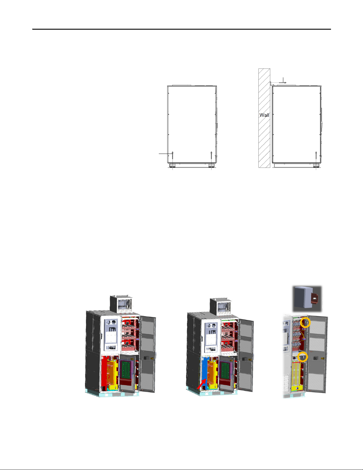
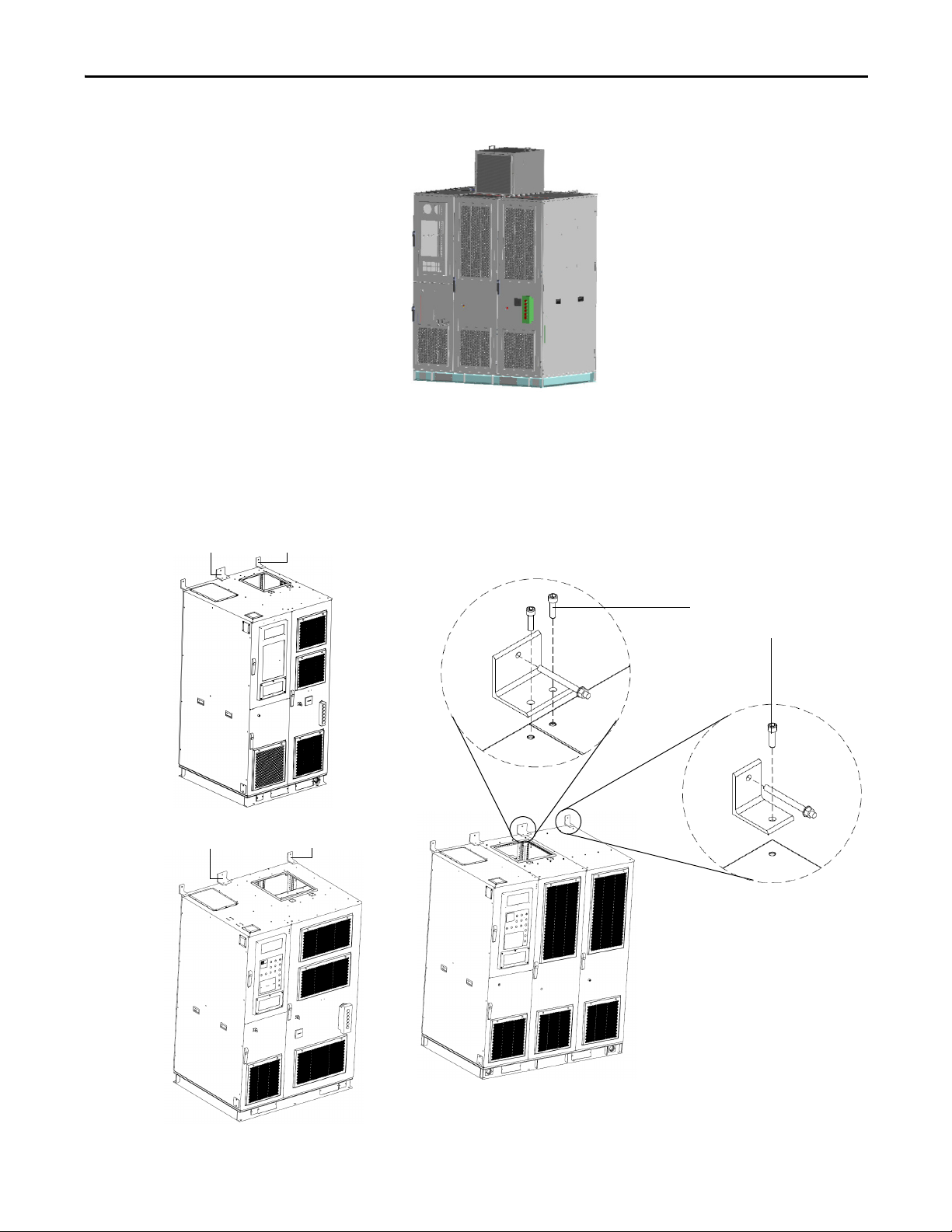
Connect DV/DT Filter Cabinet for A-Frame Drives
The standard A-Frame for PowerFlex 6000 drives comes fully assembled and does
not require any shipping splits. However, if a DV/DT filter is included with the
drive then there is one shipping split, and the drive and filter must be connected
as follows:
1. Remove the M16x16 countersunk screw that secures the LV covers and
grounding cover at the right side of the main drive, and the left side of the
filer cabinet. Then remove the covers.
2. Arrange the sections as described in the Dimensional Drawings and move
the sections together.
Rockwell Automation Publication 6000-IN006H-EN-P - October 2020 11
Page 12
Chapter 1 Drive Mechanical Installation
DV/DT Filter Cabinet
Side View
Front
Front
Isolation Transformer Cabinet
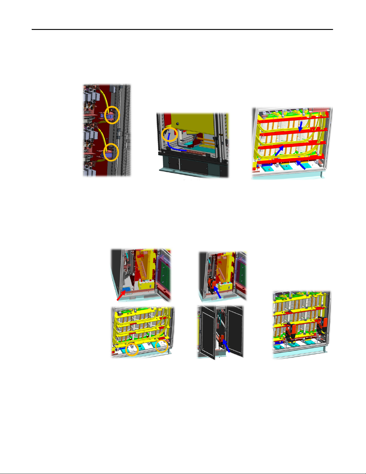
1. Align the cabinet side sheets together at the holes for the hardware.
Figure 1 - Align the Cabinets, A-Frame
2. Secure the cabinets together using two L-shaped brackets and four M12
hexagon socket bolts, D12 washers, and D12 lock washers at the front and
rear side.
12 Rockwell Automation Publication 6000-IN006H-EN-P - October 2020
Page 13
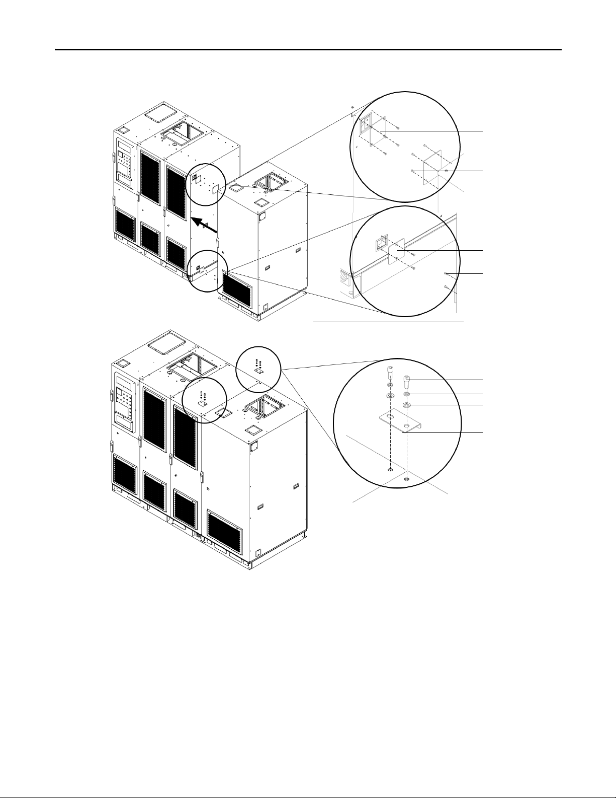
Figure 2 - Secure the Cabinets, A-Frame
LV c ove r
M16x16 countersunk
head screw (x4)
Grounding cover
M16x16 countersunk
head screw (x2)
L-shaped bracket (x2)
M12 hexagon socket
screw (x4)
D12 lock washers (x4)
D12 washers (x4)
Drive Mechanical Installation Chapter 1
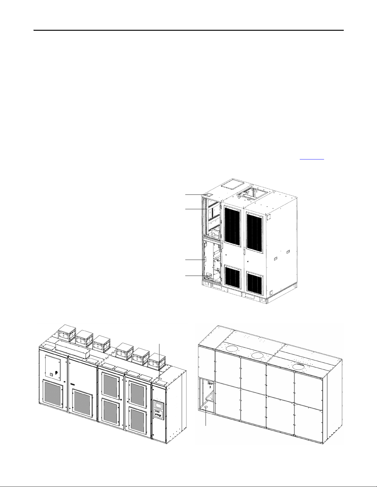
Connect Cabinets for H-Frame and B-Frame Drives
The H-Frame and B-Frame for PowerFlex 6000 drives are shipped in two
sections, the Isolation Transformer Cabinet and Power Module/LV Control
Cabinet. These two cabinets must be connected after located in its final position.
The cabinets are connected together in 8 or 10 places (depending on the drive
rating), half along the front edge of the cabinet and half along the rear edge of the
cabinet. Access to the interior of the cabinet is required to make these
connections. Access for the front connections requires only opening the doors.
Access for the rear connections requires removing the back plates of the cabinet.
Rockwell Automation Publication 6000-IN006H-EN-P - October 2020 13
Page 14
Chapter 1 Drive Mechanical Installation
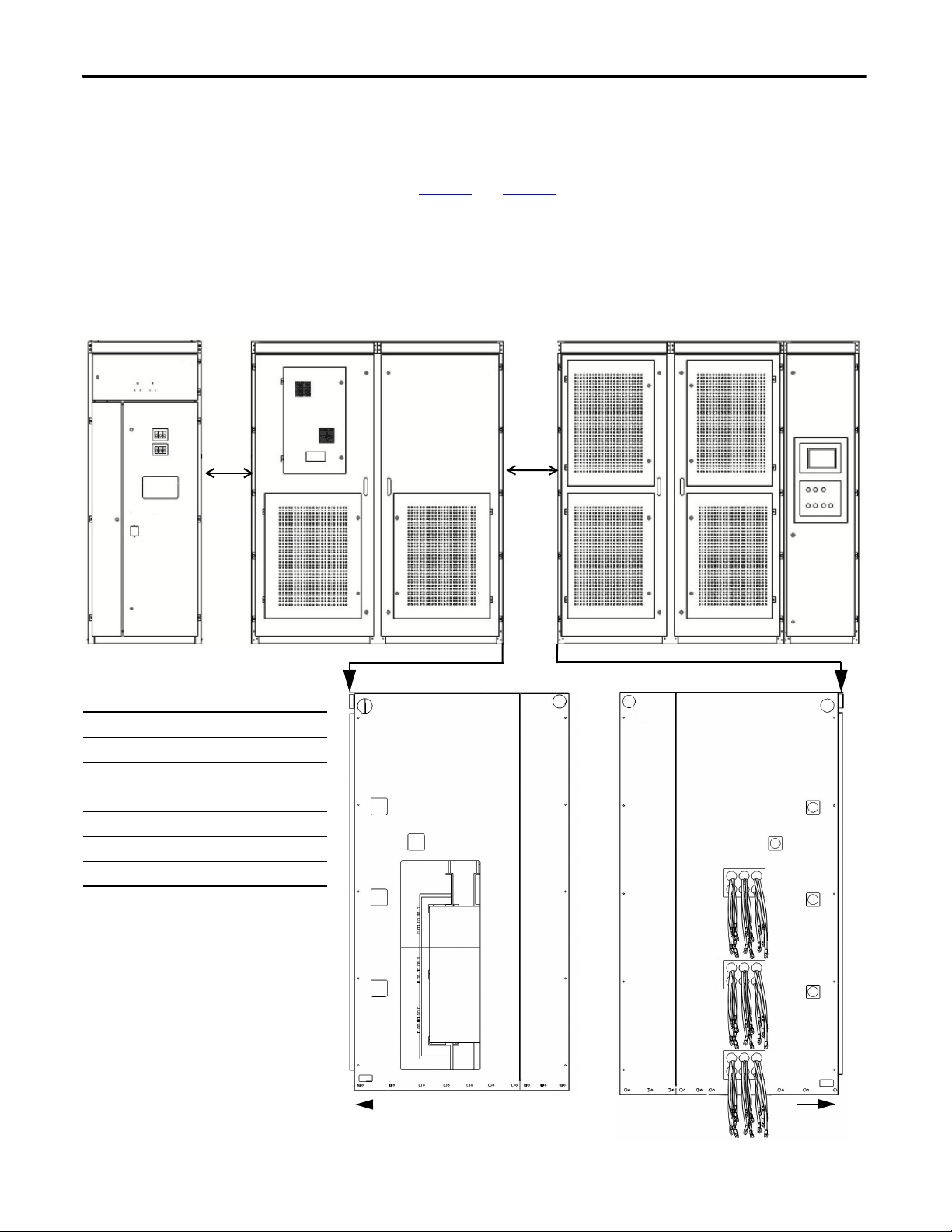
Isolation Transformer Cabinet
Power Module/LV Control Cabinet
Optional Cabinets
1. Startup cabinet (Precharge cabinet)
2. Output filter cabinet
3. Bypass cabinet
4. and others
Table 1 - Sidesheet Openings
❶
Front Wireway
❷
U Phase Motor Cable
❸
V Phase Motor Cable
❹
W Phase Motor Cable
❺
Ground Bus Connection
❻
Voltage Sensing Board Cables
❼
Isolation Transformer Secondary Cables
(1)
(1) The number of Isolation Transformer secondary cables is
dependent on motor voltage class.
• 9 cables per motor phase (27 total) for 3/3.3 kV
•12 cables per motor phase (36 total) for 4.16 kV
• 15 cables per motor phase (45 total) for 6 kV
•18 cables per motor phase (54 total) of 6.6 kV
•24 cables per motor phase (72 total) for 10 kV
• 27 cables per motor phase (81 total) for 11 kV
❶
❷
❸
❼
❹
❺
❻
❶
❸
❼
❹
❺
❻
Front
Front
❷
Side Vi ew
1. Arrange the sections as directed in the Dimensional Drawings and move
the sections together.
2. Align the cabinet side sheets together at the holes for the hardware
(see Figure 3
Figure 3 - Align the Cabinets, H-Frame (6/6.6 kV shown)
and Figure 4).
14 Rockwell Automation Publication 6000-IN006H-EN-P - October 2020
Page 15
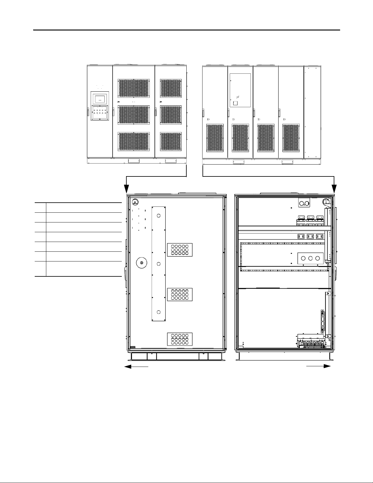
Figure 4 - Align the Cabinets, B-Frame (6 kV shown)
Isolation Transformer CabinetPower Module/LV Control Cabinet
Table 2 - Sidesheet Openings
❶
Front Wireway
❷
U Phase Motor Cable
❸
V Phase Motor Cable
❹
W Phase Motor Cable
❺
Ground Bus Connection
❻
Voltage Sensing Board Cables
❼
Isolation Transformer Secondary
Cables
(1)(2)
(1) The number of Isolation Transformer secondar y
cables is dependent on motor voltage class.
• 9 cables per motor phase (27 total) for 3/3.3 kV
•12 cables per motor phase (36 total) for 4.16 kV
• 15 cables per motor phase (45 total) for 6 kV
•18 cables per motor phase (54 total) of 6.6 kV
•24 cables per motor phase (72 total) for 10 kV
• 27 cables per motor phase (81 total) for 11 kV
(2) 6/6.6 kV configurations only require 18 cable hole
locations per phase. Extra cable hole locations allow
for added installation flexibility.
❶
❸
❹
❺
❻
❷
Front
Front
❼
Side View
❼
❼
Drive Mechanical Installation Chapter 1
Rockwell Automation Publication 6000-IN006H-EN-P - October 2020 15
Page 16
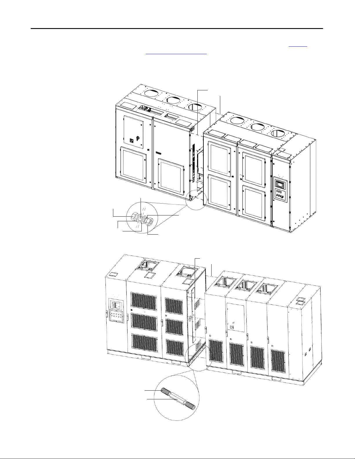
Chapter 1 Drive Mechanical Installation
Secure with M8 (or M10)
hardware (10 places)
M10x25 hex bolt
Lock washer
M10 hex nut
Flat washer (x2)
Cabinet sidesheets
Secure with M6
hardware (8 places)
2-socket screw M6x16
Combination pillar
3. Secure the cabinets together using M6 or M8 hardware. See To r q u e
Requirements on page 69 for proper torque requirements.
Open the doors to access front edge joining holes (four or five places).
Figure 5 - Secure the Cabinets, H-Frame
Figure 6 - Secure the Cabinets, B-Frame
16 Rockwell Automation Publication 6000-IN006H-EN-P - October 2020
Page 17
Drive Mechanical Installation Chapter 1
TIP
Isolation Transformer Cabinet Power Module/LV Control Cabinet
Bottom View
4. Remove all back plates to access rear edge joining holes (five places).
Each back plate will have two keyhole screw holes on either side. Remove all
other screws first. Loosen the two screws in the keyhole screw holes last and
lift the back plate to remove. Do not remove these screws.
Do not replace the back plates until the Drive Electrical Interconnection Process
is complete (See Drive Electrical Interconnection
on page 57).
To replace the back plates, the two remaining screws orient and hold the back
plate in place while fastening the other screws holding the back plates to the
frame of the cabinet. Tighten these screws last to complete the process.
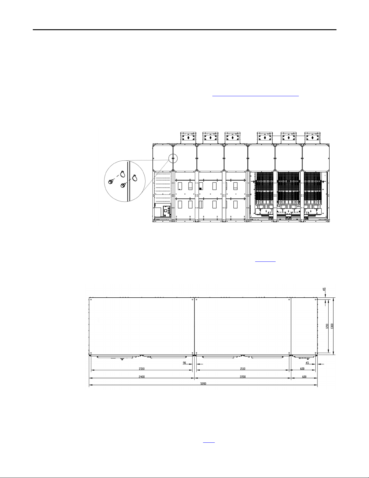
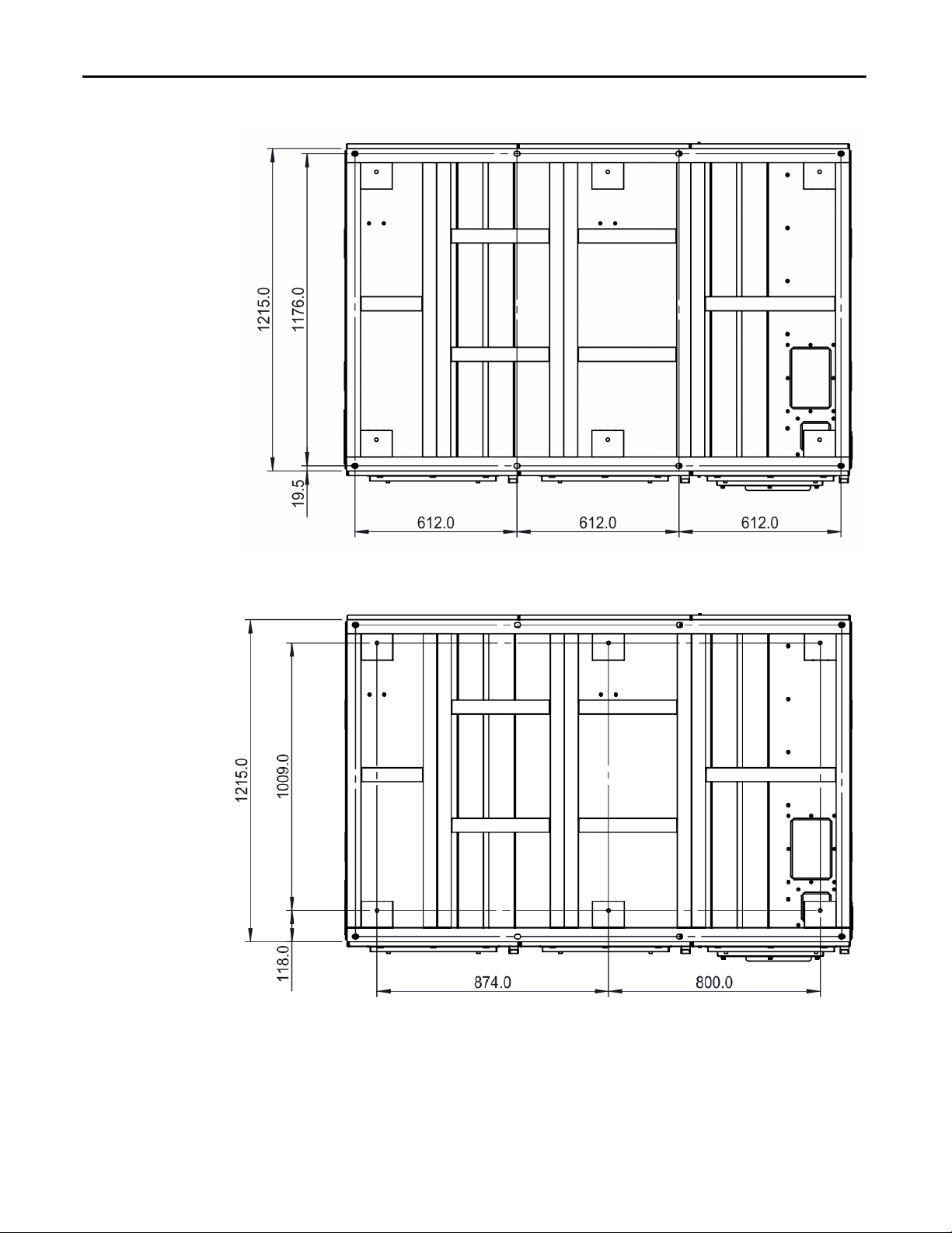
Affix Cabinets to Floor
Typical floor drawings show minimum clearance distance, conduit openings, and
(1)
mounting holes for anchor bolts
, as shown in Figure 7. See customer-specific
dimensional drawing for outgoing motor and incoming line cable openings.
Figure 7 - Typical Floor Drawing, H-Frame
Secure the cabinet to the channel steel base using M16 bolt, lock washer, two flat
washers, and a nut.
(1) Mounting holes are represented as + in Figure 7.
Rockwell Automation Publication 6000-IN006H-EN-P - October 2020 17
Page 18
Chapter 1 Drive Mechanical Installation
Isolation Transformer CabinetPower Module/LV Control Cabinet
Bottom View
Control signal
Output cable
Input cable
M16 bolt
Flat washer
Lock wash er
M16 bolt
Flat washer
Lock wash er
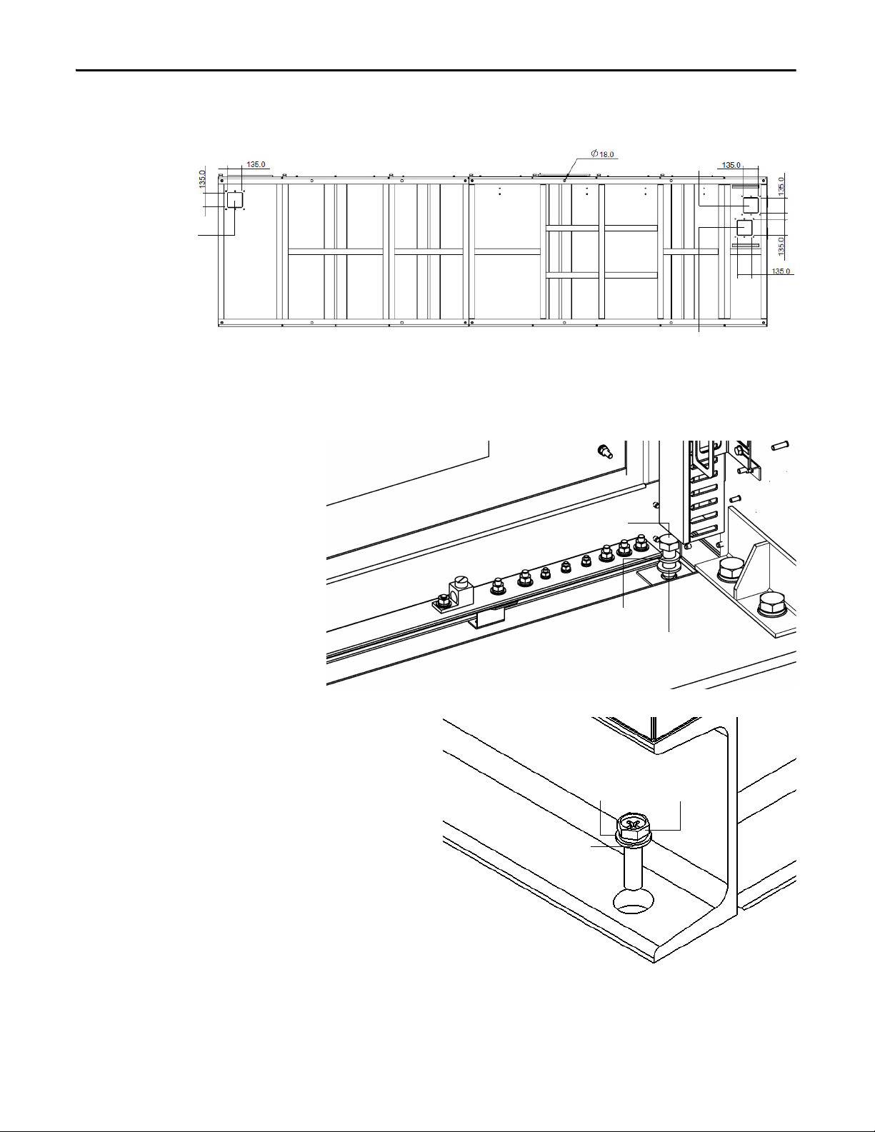
Figure 8 - Typical Floor Drawing, B-Frame
Secure the cabinet to the channel steel base using M12 bolt (recommended), lock
washer, two flat washers, and a nut.
Figure 9 - Bolt Cabinet to Steel Base, H-Frame
Figure 10 - Bolt Cabinet to Steel Base, B-Frame
18 Rockwell Automation Publication 6000-IN006H-EN-P - October 2020
Page 19
Drive Mechanical Installation Chapter 1
Channel steel baseRecommended weld locations
Optional: The cabinet can also be welded to the steel base once it is securely
bolted, if desired.
Each weld location should be 100 mm (3.9 in.) for every 1000 mm (39.4 in.). See
Mounting Requirements in the PowerFlex 6000 Medium Voltage Variable
Frequency Drive Shipping and Handling Manual, publication 6000-IN008
) for
further information on the steel base and desired trench and mounting customerspecifications.
Figure 11 - Welding locations
ATT EN TI ON : Failure to correctly anchor the cabinet may result in damage to the
equipment or injury to personnel.
Rockwell Automation Publication 6000-IN006H-EN-P - October 2020 19
Page 20
Chapter 1 Drive Mechanical Installation
Non-seismic
Seismic
Figure 12 - Typical Floor Drawing, A-Frame
Secure the cabinet to the channel steel base using M12 bolt (recommended), lock
washer, two flat washers, and a nut.
20 Rockwell Automation Publication 6000-IN006H-EN-P - October 2020
Page 21
Drive Mechanical Installation Chapter 1
Condition 1
Anchors braced at front
and rear side
Condition 2
Anchors braced at front
and wall-mounted angle
1/2” Anchor bolt
Effective embedded depth 5”
1/2” Anchor bolt
Step 1 Step 3Step 2
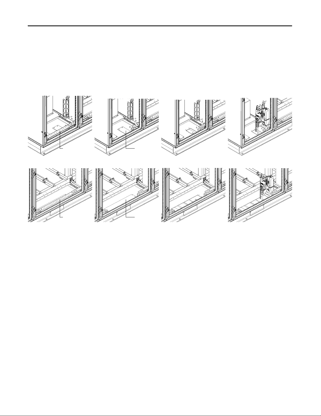
Install Seismic Rated Enclosures
This section describes how to install the drive for seismic conditions.
Figure 13 - Guidance for Seismic Installation
Install A-Frame Drives
For condition 1, 70 A seismic installation, follow these instructions:
1. Open MV front door and back door.
2. Remove the JC front barrier.
3. Remove two thermostats from the DIN rail in PC and TC at the right-
hand side of the cabinet.
Rockwell Automation Publication 6000-IN006H-EN-P - October 2020 21
Page 22
Chapter 1 Drive Mechanical Installation
Step 4 Step 6Step 5
Step 7 Step 9Step 8
4. Remove the HECS insulation bracket.
5. Remove the grounding terminal of the right side plate at the back side.
6. Remove the right side plate, put the secondary cables close to Tx winding,
and disassemble three horizontal baffles.
7. Remove the seismic cover at the front and back side of the JC, and the
right side of the drive.
8. Drill anchor holes at the left-hand side of the cabinet.
9. Drill anchor holes at the right-hand side of the cabinet, then install the
anchors.
22 Rockwell Automation Publication 6000-IN006H-EN-P - October 2020
Page 23
Drive Mechanical Installation Chapter 1
Step 10
Step 1 Step 3Step 2
Step 4 Step 5
10. Install the parts in reverse order of removal.
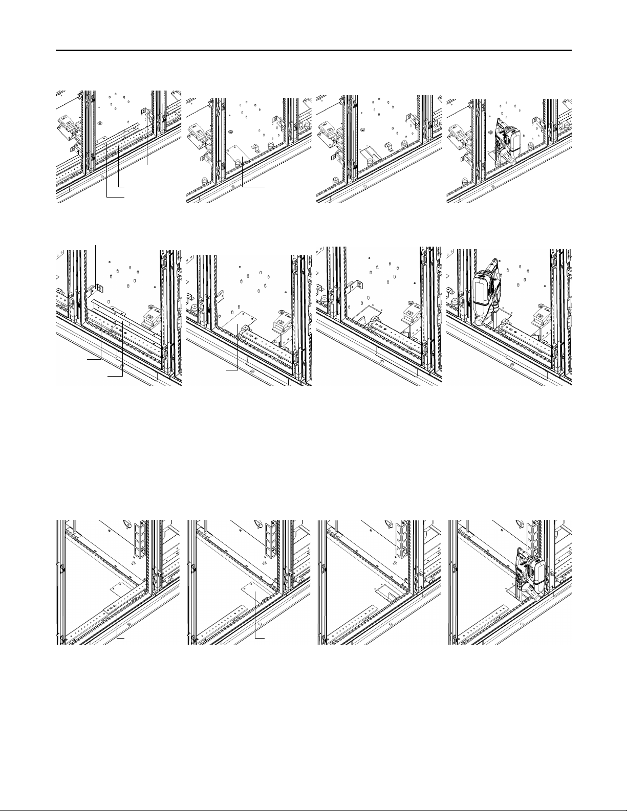
For condition 1, 140 A seismic installation, follow these instructions:
1. Open MV front door and back door.
2. Remove the JC front barrier.
3. Remove the back horizontal baffles, cable bracket, and all seismic covers.
4. Drill anchor holes at the back of the cabinet.
5. Drill anchor holes at the front of the cabinet.
Rockwell Automation Publication 6000-IN006H-EN-P - October 2020 23
Page 24
Chapter 1 Drive Mechanical Installation
Step 6
Step 1 Step 3Step 2
Step 4 Step 5
6. Install the removed parts in reverse order of removal.
For condition 1, 215 A seismic installation, follow these instructions:
1. Open MV front door and back door.
2. Remove the JC front barrier.
3. Remove the back horizontal baffles and all seismic covers.
4. Drill anchor holes at the front of the cabinet.
5. Drill anchor holes at the back of the cabinet.
24 Rockwell Automation Publication 6000-IN006H-EN-P - October 2020
Page 25
Drive Mechanical Installation Chapter 1
Step 6
Frame 1
Frame 3
Wall bracket B
Wall bracket A
Wall bracket B Wall bracket A
Wall bracket B Wall bracket A
Frame 2
M12xL35
Based on bracket thickness
of 11 mm (0.43 in.)
6. Install the removed parts in reverse order of removal.
For condition 2 seismic installation, if there is no rear access available, the top of
the drive can be mounted to the wall rather than mounted to the floor at the back
of the cabinet. If there is a fan redundancy condition for frame 1 and frame 2,
then wall bracket B is not needed.
Rockwell Automation Publication 6000-IN006H-EN-P - October 2020 25
Page 26
Chapter 1 Drive Mechanical Installation
Step 1 Step 3Step 2Left cabinet
Grounding busbar Anchor cover
Step 1 Step 3Step 2Middle cabinet
Grounding busbar Anchor cover
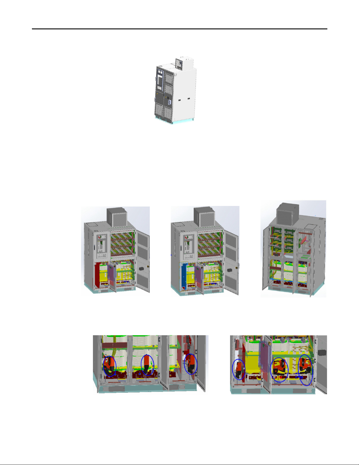
Install B-Frame Drives
For condition 1, installation of power cell cabinets, follow these instructions:
1. Disassemble the grounding busbar at the front of the cabinet.
2. Disassemble the anchor cover at the front of the cabinet.
3. Drill an anchor hole.
For condition 1, installation of transformer cabinets, follow these instructions:
1. Disassemble the grounding busbar, wire duct, and barrier bracket at the
2. Disassemble the anchor cover at the front of the cabinet.
front of the cabinet.
26 Rockwell Automation Publication 6000-IN006H-EN-P - October 2020
Page 27
3. Drill an anchor hole.
Step 1 Step 3Step 2Left cabinet
Grounding busbar
Anchor cover
Step 1 Step 3Step 2Right cabinet
Grounding
busbar
Anchor cover
Wire d uct
Barrier bracket
Barrier bracket
Wire d uct
Step 1 Step 3Step 2Standard or filter cabinet
Grounding busbar Anchor cover
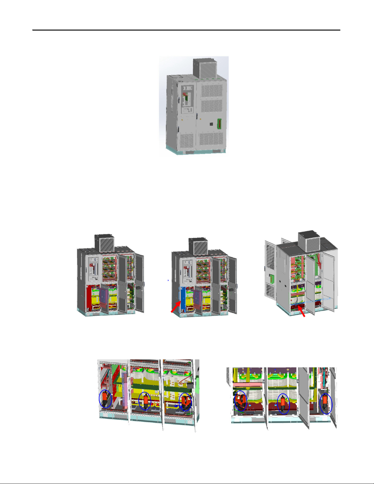
Drive Mechanical Installation Chapter 1
For condition 1, installation of standard cabinets and filter cabinets, follow these
instructions:
1. Disassemble the grounding busbar at the front of the cabinet.
2. Disassemble the anchor cover at the front of the cabinet.
3. Drill an anchor hole.
Rockwell Automation Publication 6000-IN006H-EN-P - October 2020 27
Page 28

Chapter 1 Drive Mechanical Installation
Wall bracket B Wall bracket A
M12xL35
Based on bracket thickness
of 11 mm (0.43 in.)
Wal l bra cket BWall br acke t A
For condition 2 seismic installation, if there is no rear access available, the top of
the drive can be mounted to the wall rather than mounted to the floor at the back
of the cabinet.
Figure 14 - ASTM A36 Angle Bracket Dimensions
28 Rockwell Automation Publication 6000-IN006H-EN-P - October 2020
Page 29

Drive Mechanical Installation Chapter 1
IMPORTANT
Main Cooling Fan housing
Aviation plug
Socket
Rear View
M6 tapping screws or bolts
Install Main Cooling Fans
Main cooling fans are shipped in separate crates. The fans are shipped assembled
in the fan housing, but must be installed after siting the drive.
See Mounting Clearance Distance in the PowerFlex 6000 Medium Voltage
Variable Frequency Drive Shipping and Handling Manual, publication 6000-
IN008) to verify that the fans have the appropriate clearance distance on top of
the cabinet.
Table 3 - Fan Housing Specifications
Model Dimensions (HxWxD), approx. Weight, approx.
RH40 340 x 440 x 500 mm (13.0 x 17.3 x 19.7 in.) 20 kg (44.1 lb)
RH45 380 x 490 x 550 mm (14.6 x 19.3 x 21.7 in.) 25 kg (55.1 lb)
EC400 428 x 480 x 672 mm (16.9 x 18.9 x 26.5 in.) 30 kg (66 lb)
EC500 520 x 580 x 783 mm (20.5 x 22.8 x 30.8 in.) 45 kg (99 lb)
520 x 580 x 1125 mm (20.5 x 22.8 x 44.3 in.) 60 kg (132 lb)
1. Place the fan housing on the top plate of the drive, making sure that the
socket is on the same side as the aviation plug.
2. Secure the fan housing using M6 hardware (six places).
3. Connect the aviation plug located on top of the cabinet with the socket on
Figure 15 - Main Cooling Fan Housing, H-Frame
See Torque Requirements
the fan housing.
on page 69.
Rockwell Automation Publication 6000-IN006H-EN-P - October 2020 29
Page 30

Chapter 1 Drive Mechanical Installation
Main Cooling Fan housing
Aviati on plug
Socket
Rear View
Aviation pl ug
Socket
Main Cooling Fan housing
Noise reduction barrier
Figure 16 - Main Cooling Fan Housing, B-Frame
Install the Cooling Fan and Noise Reduction Barrier for A-Frame Drives
To install the cooling fan for A-Frame drives, follow these instructions.
1. Place the fan housing on the top plate of the drive. Verify that the socket is
2. Secure the fan housing using M6 hardware (six places).
3. Connect the aviation plug located on the top of the cabinet with the socket
Figure 17 - Main Cooling Fan Housing, A-Frame
on the same side as the aviation plug.
on the fan housing.
30 Rockwell Automation Publication 6000-IN006H-EN-P - October 2020
Page 31

Drive Mechanical Installation Chapter 1
If your application uses noise reduction barriers for the fans, follow these
instructions.
1. Remove the four M6 screws on the left and right sides of the front fan
housing.
2. Place the noise reduction barrier in front of the fan housing.
3. Secure the noise reduction barrier wit h the four M6 screws.
Figure 18 - Install the Noise Reduction Barrier
Install the Mixing Hood for A-Frame Drives
If your application uses a mixing hood with redundant fan, follow these
instructions.
1. Remove the air hood from the skid.
2. Install the four eyebolts at each corner of the air hood.
3. Life the air hood by the four eyebolts and align with the provisions on the
top plate.
4. Secure the air hood with 12 M16x16 hexagon combination screws.
5. Put the fan modules onto the air hood and align with the provisions on the
air hood.
6. Secure the fan modules with 16 M16x16 hexagon combination screws.
Rockwell Automation Publication 6000-IN006H-EN-P - October 2020 31
Page 32

Chapter 1 Drive Mechanical Installation
M16x16 hexagon
combination screw (16)
M16x16 hexagon
combination screw (12)
Eyebolt ( 4)
Figure 19 - Install a Mixing Hood with Redundant Fan
Install Power Modules (if applicable)
Power Modules are available in a wide variety of amperage ratings relating to the
required motor current. Power Modules that are rated up to and including 350 A
are mounted in the drive and ship already installed.
Power Modules that are rated above 350 A are shipped separately, therefore site
installation and cable connection is needed. In this case, a lift cart is supplied and
shipped together with the other components.
Power Module Lift Cart
ATT EN TI ON : Only authorized personnel should operate the lift cart. Keep hands
and feet away from the lifting mechanism. Do not stand under the lift tray
when in use. Store the lift cart with the tray fully lowered.
The lift cart’s hydraulic cylinder can be operated by either a hand or foot crank.
The lifting capacity is 400 kg (882 lb).
32 Rockwell Automation Publication 6000-IN006H-EN-P - October 2020
Page 33

Figure 20 - Lift Cart Procedure
Hand Crank
Foot C rank
Pressure Release Knob
1. Check the lift tray before use to ensure that the
tray can be raised and lowered smoothly.
2. Rotate the Pressure Release Knob
counterclockwise to ensure that the tray is in
the lowest position.
3. Move the Power Module on the tray and lift
the module to the appropriate height using the
Foot Crank and complete the installation.
4. Rotate the Pressure Release Knob
counterclockwise to lower the tray to its
original position.
5. Repeat steps 1...4 to complete the installation
for all Power Modules.
TIP
The Foot Crank raises the lift tray faster than
the Hand Crank. Use this to raise the Power
Module to just below the tray assembly in
the drive. Use the Hand Crank for final
precise positioning.
Lift tray
Release
pressure in
cylinder
Seal
pressure in
cylinder
Drive Mechanical Installation Chapter 1
Rockwell Automation Publication 6000-IN006H-EN-P - October 2020 33
Table 4 - Power Module Specifications
Frame Output Rating (Amps) Dimensions (HxWxD), approx. Weight, approx.
A-Frame 36…70 A 210 x 110 x 569 mm (8.3 x 4.3 x 22.4 in.) 13 kg (28.6 lb)
71…140 A 210 x 190 x 624.5 mm (8.3 x 7.5 x 24.6 in) 25 kg (55 lb)
141…215 A 210 x 215 x 674 mm (8.3 x 8.5 x 26.5 in) 35 kg (77 lb)
H-Frame ≤150 A 420 x 180 x 615 mm (16.5 x 7.1 x 24.2 in.) 20 kg (44.1 lb)
151…200 A 420 x 260 x 615 mm (16.5 x 10.2 x 24.2 in.) 25 kg (55.1 lb)
B-Frame 201…350 A 552.5 x 244.5 x 663 mm (21.8 x 9.6 x 26.1 in.) 70 kg (154 lb)
351…680 A 471 x 354 x 746 mm (18.5 x 13.9 x 29.4 in.) 95 kg (209 lb)
ATT EN TI ON : Two people are required to handle the Power Modules.
Page 34

Chapter 1 Drive Mechanical Installation
IMPORTANT
Mounting brackets
Power Modu le
Guide rail
Mounting brackets
IMPORTANT
Install Power Modules
The Power Module should be handled carefully. After removing the packaging,
inspect the Power Module to confirm that there is no damage and moisture.
1. You can use the lift cart to move and position the Power Module to the
appropriate location in the cabinet.
2. Push the Power Module slowly along the guide rails until it cannot be
pushed in further.
3. After installing the Power Module in place, use the mounting brackets and
the M6 × 16 large flat pad galvanized nickel screws to fix the four corners,
as shown below.
Install Power Modules for A-Frame Drives
The Power Module should be handled carefully. After removing the packaging,
inspect the Power Module to confirm that there is no damage and moisture.
1. Push the Power Module slowly along the guide rails until it cannot be
pushed in further.
2. After installing the Power Module in place:
34 Rockwell Automation Publication 6000-IN006H-EN-P - October 2020
Page 35

Drive Mechanical Installation Chapter 1
Mounting brackets
Power Module
Guide rail
Secure points
Power Module
Guide rail
a. For 140/215 A rating – use the mounting brackets and M6x16 large flat
pad galvanized nickel screws to secure the two bottom corners.
b. For 70 A rating – use M16x16 large flat pad galvanized nickel screws to
the two bottom corners directly.
secure
Rockwell Automation Publication 6000-IN006H-EN-P - October 2020 35
Page 36

Chapter 1 Drive Mechanical Installation
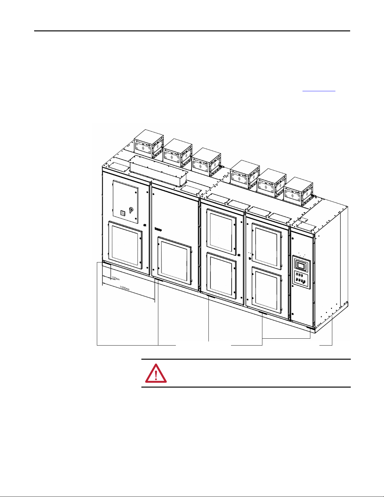
External Ducting
The PowerFlex 6000 design can accommodate ducting exhaust air outside of the
control room.
ATT EN TI ON : The Isolation Transformer Cabinet and the Power Module/LV
Control Cabinet must be ducted separately.
The following requirements are mandatory design requirements for systems that
will externally duct the exhaust air and draw cleansed outside air:
• External ducting including an external filtering system must not add more
than 50 Pa (0.2 in. of water) pressure drop to the PowerFlex 6000 drive
airflow system. Ensure a minimum top clearance of 1500 mm (39.4 in.)
above the drive top plate.
• The control room must provide slightly more make-up air, creating a
pressurized room. This slight pressurization prevents unfiltered air
drawing into the room.
• The drive is intended to operate in conditions with no special precautions
to minimize the presence of sand or dust, but not in close proximity to
sand or dust sources. IEC 721-1 defines this as being less than 0.2 mg/m
3
of dust.
• If outside air does not meet this condition, filter the air to EU EN779
Class F6 or ASHRAE Standard 52.2 MERV 11. These ratings address a
high percentage of the 1.0...3.0 μm particle size. Clean or change filters
regularly to ensure proper flow.
• The make-up air must be between 0...40 °C (32...104°F).
• Relative humidity must be less than 95% noncondensing.
• If the ducting length is greater than 4 m (13 ft), an axial fan must be
installed at the air outlet. The exhaust flow of the axial fan must be greater
than the total flow amount of all centrifugal fans in this air duct.
• The ducting can be shared by more than one cabinet.
• Do not cover any medium voltage or control power wires that enter or exit
from the top of the cabinet.
• The air duct outlet must slope downward to prevent water damage.
• Screens must be installed in the air duct outlet.
• An air inlet must be added to the drive room. The cross-sectional area of
this inlet must meet the ventilation requirements of all drives. Screens
must be installed in the air inlet.
• The air inlet and outlet must not be at the same side of the drive room.
36 Rockwell Automation Publication 6000-IN006H-EN-P - October 2020
Page 37

Drive Mechanical Installation Chapter 1
Figure 21 - Cabinet Airflow, A-Frame
(1)
Figure 22 - Cabinet Airflow, H-Frame
(1)
(1) Top ducting shown by contractor.
Rockwell Automation Publication 6000-IN006H-EN-P - October 2020 37
Page 38

Chapter 1 Drive Mechanical Installation
EXAMPLE
DriveRating kW1 DriveEfficiency–
3.5
-------------------------------------------------------------------------------------------------------------
=
1000 1 0.965
·
–
3.5
----------------------------------------------
10=
Figure 23 - Cabinet Airflow, B-Frame
(1)
Air Conditioning Sizing
If the drive is located in an enclosed space, install air conditioners for each drive.
A general formula to calculate air conditioner power required:
Air Conditioning Size (tons)
For a 1000 kW drive with 96.5% efficiency:
tons of AC required
This is for a general estimate. See the actual heat loss data to calculate air
conditioning sizing. Contact the local Rockwell Automation office for actual
data.
38 Rockwell Automation Publication 6000-IN006H-EN-P - October 2020
Page 39

Drive Electrical Installation
Chapter 2
Introduction
Safety and Codes
The installation of all external power cables and control signal wiring is covered
in this chapter. General electrical safety and installation guideline topics are also
included. The basic activities include connecting the system ground cable, line
and motor cables, control power, and all control signal wiring from the sources to
the drive. See Figure 45
Electrical interconnections are also required between cabinets that have shipped
separately. These are described in Drive Electrical Interconnection
SHOCK HAZARD: Connecting to potentially energized industrial control
equipment can be dangerous. Severe injury or death can result from electrical
shock, burn, or unintended actuation of control equipment. Hazardous voltages
may exist in the cabinet even with the circuit breaker in the off position.
Required practice is to disconnect and lock out control equipment from power
sources, and confirm discharge of stored energy in capacitors. If it is necessary
to work in the vicinity of energized equipment, the safety-related work
practices that are outlined in Electrical Safety requirements for Employee Work
places must be followed. Before attempting any work, verify that the system
has been locked out and tested to have no potential.
and Figure 46 for an overview of these connections.
on page 57.
Lockout and tagout the input circuit breaker before performing any electrical
connection work. After the input circuit breaker cabinet doors are opened,
immediately test the outgoing connections and any components that are
connected to medium voltage with a live-line tool (hot stick) while wearing highvoltage gloves. Pay special attention to any capacitors connected to medium
voltage that can retain a charge for a period of time. Only after the equipment has
been verified as isolated and de-energized can subsequent work be performed.
Even though the input to the drive may be open, it is still possible for hazardous
voltage to be present.
See national and local safety guidelines for detailed procedures on how to safely
isolate the equipment from hazards.
ATT EN TI ON : The national and local electrical codes outline provisions for safely
installing electrical equipment. Installation must comply with specifications
regarding wire type, conductor sizes, branch circuit protection, and disconnect
devices. Failure to do so may result in personal injury and/or equipment
damage.
Rockwell Automation Publication 6000-IN006H-EN-P - October 2020 39
Page 40

Chapter 2 Drive Electrical Installation
Electrical Drawings
Before connecting any power cables or control signal wiring, review and
understand the information that is contained in the project-specific Electrical
Drawings.
They contain critical information such as:
• Minimum power cable insulation ratings and sizes
• Power terminal locations and designations
• Terminal block designations for all connections to external customer
control signal wiring and control power supply cables.
The practice that is used within the PowerFlex 6000 electrical drawing is based
on the IEC or NEMA standard depending on the requirements. The symbols
used to identify components on the drawings are international.
Device designations that are used on the drawings and labeling are explained on
each drawing set.
Wiring identification uses a source/destination wire number convention on
point-to-point multi-conductor wiring and in situations where the system is
warranted. The wire-numbering system of unique, single numbers for multi-drop
and point-to-point wiring continues to be used for general control and power
wiring.
Grounding System Requirements
Wiring that connects between the sheets or that ends at one point and starts at
another point on a drawing has an arrow and drawing reference to indicate the
ongoing connection. The drawing reference indicates the sheet and the X/Y
coordinates of the continuation point. The reference system is explained on a
sheet in each drawing set. The unique wire numbering system serves as
confirmation that the correct wire is being traced from sheet-to-sheet or across a
drawing. Wires in multi-conductor cables are typically identified by color rather
than by number. Abbreviations used to identify the colors on the drawings are
fully identified on a sheet in the drawing set.
As a general guideline, the ground path must be of sufficiently low impedance
and capacity that:
• the rise in potential of the drive ground point when subjected to a current
of twice the rating of the supply should be no higher than 4V over ground
potential
• the current flowing into a ground fault is of sufficient magnitude to cause
the protection to operate.
The general grounding point must be reliably connected with the grounding
network.
40 Rockwell Automation Publication 6000-IN006H-EN-P - October 2020
Page 41

Drive Electrical Installation Chapter 2
IMPORTANT
IMPORTANT
Attach an external ground cable to the main ground bus, in compliance with
applicable national and local electrical codes.
The primary grounding cable must have a diameter of at least 50 mm2 and
meet all applicable national and local electrical codes.
Run the system ground cable separately from power and signal wiring so that
faults:
• do not damage the grounding circuit
• will not interfere with or damage the protection or metering systems, or
cause undue disturbance on power lines.
Power Cable Insulation Requirements
Incoming line power cable ratings are shown on the Electrical Drawings and
reflect what would typically be supplied, based on line voltage rating.
All voltage ratings for outgoing motor cables that are shown are line-to-ground
rated power-frequency voltages and line-to-line power-frequency voltages.
Table 5 - Cable Insulation Requirements for Outgoing Motor Cables
System Voltage
(V, RMS)
2300 ≥1.7 ≥2.8
2400 ≥1.7 ≥2.8
3000 ≥2.3 ≥3.9
3300 ≥2.3 ≥3.9
4000 ≥2.8 ≥4.8
4160 ≥2.8 ≥4.8
6000 ≥4.0 ≥6.9
6300 ≥4.5 ≥7.8
6600 ≥4.5 ≥7.8
6900 ≥4.8 ≥8.3
10,000 ≥6.4 ≥11.1
11,000 ≥7.2 ≥12.5
Line-to-Ground Rated Power
Frequency Voltage U
Minimum Insulation Rating (kV ) - Motor Side
Line-to-Line Rated Power
o
Frequency Volta ge U
Select cables of appropriate voltage classes when the incoming line grid-side
voltage class differs from the outgoing line motor-side voltage class.
Standard power cable ratings commercially available can vary in different regions
around the world. Cable must meet the minimum line-to-ground and line-toline requirements.
Follow the recommended field power cabling insulation levels to help ensure
trouble-free startup and operation. The cable insulation level must be
increased over that which would be supplied for an across-the-line application
with the same rated line-to-line voltage.
Rockwell Automation Publication 6000-IN006H-EN-P - October 2020 41
Page 42

Chapter 2 Drive Electrical Installation
IMPORTANT
Power Cable Design Considerations
Use fire retardant cables for the drive input/output connections.
Shielded or unshielded cable can be used based on the criteria that are considered
by the distribution system designer and national and local electrical codes.
If shielded power cables are used, connect the shield of the main input/output
power cables with the general grounding point of the drive. Ground the drive
output protective grounding connection separately, and only at the drive side.
Comply with the maximum tensile stress and the minimum curvature radius that
is recommended by the cable manufacturer.
Do not bundle the input/output cables of the drive together.
The power cable tray must not be less than 300 mm (12 in.).
There must be no gaps where the conduit connects to the cabinet and the ground
bond must be less than 0.1 ohms. Spacing between wire groups is the
recommended minimum for parallel runs of approximately 61 m (200 ft) or less.
PowerFlex 6000 drives are able to operate motors if the cable length is less
than 800 m (2624 ft). Contact the factory when cable lengths at the drive
output exceed 800 m (2624 ft).
When the cable length is longer than 800 m (2624 ft), an assessment is
required. It does not necessarily mean that an output filter is required.
Configurations can be provided for longer cable distances, but must be
specified at the time of order.
Motor Cable Sizing
All input and output power wiring, control wiring, or conduit must be brought
through the conduit entrance holes of the cabinet. Use appropriate connectors to
maintain the environmental rating of the cabinet.
Voltage drop in motor leads may adversely affect motor starting and running
performance. Installation and application requirements may dictate that larger
wire sizes than indicated in national and local electrical codes are used.
Wire sizes must be selected individually, observing all applicable safety and
national and local electrical codes. The minimum permissible wire size does not
necessarily result in the best operating economy. The minimum recommended
size for the wires between the drive and the motor is the same as that used if a
main voltage source connection to the motor was used. The distance between the
drive and motor can affect the size of the conductors used.
Consult the Electrical Drawings and appropriate national and local electrical
codes to determine correct power wiring. If assistance is needed, contact your
local Rockwell Automation Sales Office.
42 Rockwell Automation Publication 6000-IN006H-EN-P - October 2020
Page 43

Drive Electrical Installation Chapter 2
Control Signal Wiring Design Considerations
Use shielded cables for all analog and digital control cables.
Steel conduit or a cable tray can be used for all PowerFlex 6000 drive power or
control wiring; however, use only steel conduit for all signal wiring.
ATT EN TI ON : Steel conduit is required for all control and signal circuits when
the drive is installed in European Union countries.
Wires for digital and analog signals must be routed separately.
Control cables and power cables must be routed separately; the distance between
the control cable tray and the power cable tray must not be less than 300 mm
(11.8 in.).
If the control cable must pass through the power cable tray, the angle between the
cable trays must be as close to 90° as possible.
Do not mix AC and DC wires in the same cable bundle.
General Wire Categories
installing the PowerFlex 6000 drive. Each category has an associated wire group
number that is used to identify the required wire. Application and signal
examples, along with the recommended type of cable for each group, are
provided. A matrix providing the recommended minimum spacing between
different wire groups that run in the same tray or in a separate conduit is also
provided.
on page 71 identifies general wire categories for
Control Signal Wire Shield Grounding
Guidelines for Drive Signal and Safety Grounds: when using interface cables
carrying signals, where the frequency does not exceed 1 MHz, for
communications with the drive, follow these general guidelines:
• Ground screen mesh around the entire circumference, rather than forming
a pigtail grounded only at one point.
• For coaxial cables with a single conductor surrounded by a mesh screen,
ground the screen at both ends.
• When using a multi-layer screened cable (that is, a cable with both a mesh
screen and a metal sheath or some form of foil), there are two alternative
methods:
– Ground the mesh screen at both ends to the metal sheath. The metal
sheath or foil (known as the drain) should, unless otherwise specified,
be grounded at one end only, again, as specified above, at the receiver
end or the end that is physically closest to the main equipment ground
bus
– Leave the metal sheath or foil insulated from ground, and ground the
other conductors and the mesh cable screen at one end only, as stated
above.
Rockwell Automation Publication 6000-IN006H-EN-P - October 2020 43
Page 44

Chapter 2 Drive Electrical Installation
Vertical Ground Bus
Provisions for Grounding
Control Signal Wiring Shields,
and so on.
Ground Bus
Provisions for Grounding
Control Signal Wiring Shields,
and so on.
Ground Bus
H-Frame B-Frame
A-Frame
Provisions for Grounding
Control Signal Wiring Shields,
and so on.
Ground Bus
Grounding provisions for control signal wiring is shown in Figure 24.
Figure 24 - Vertical Ground Bus in LV Cabinet
Electrical Installation Summary
Connect External Cabling and Wiring Page
Connect the System Ground Cable 45
Insulation Resistance (IR) Test of Power Cables 46
Connect Incoming Line and Outgoing Motor Power Cables 46
Connec t Control Powe r Wiring 51
Connec t External Cont rol Signal Wiring 53
Connect Electrical Safety Interlock Circuit to Input Circuit Breaker 54
44 Rockwell Automation Publication 6000-IN006H-EN-P - October 2020
Page 45
Drive Electrical Installation Chapter 2
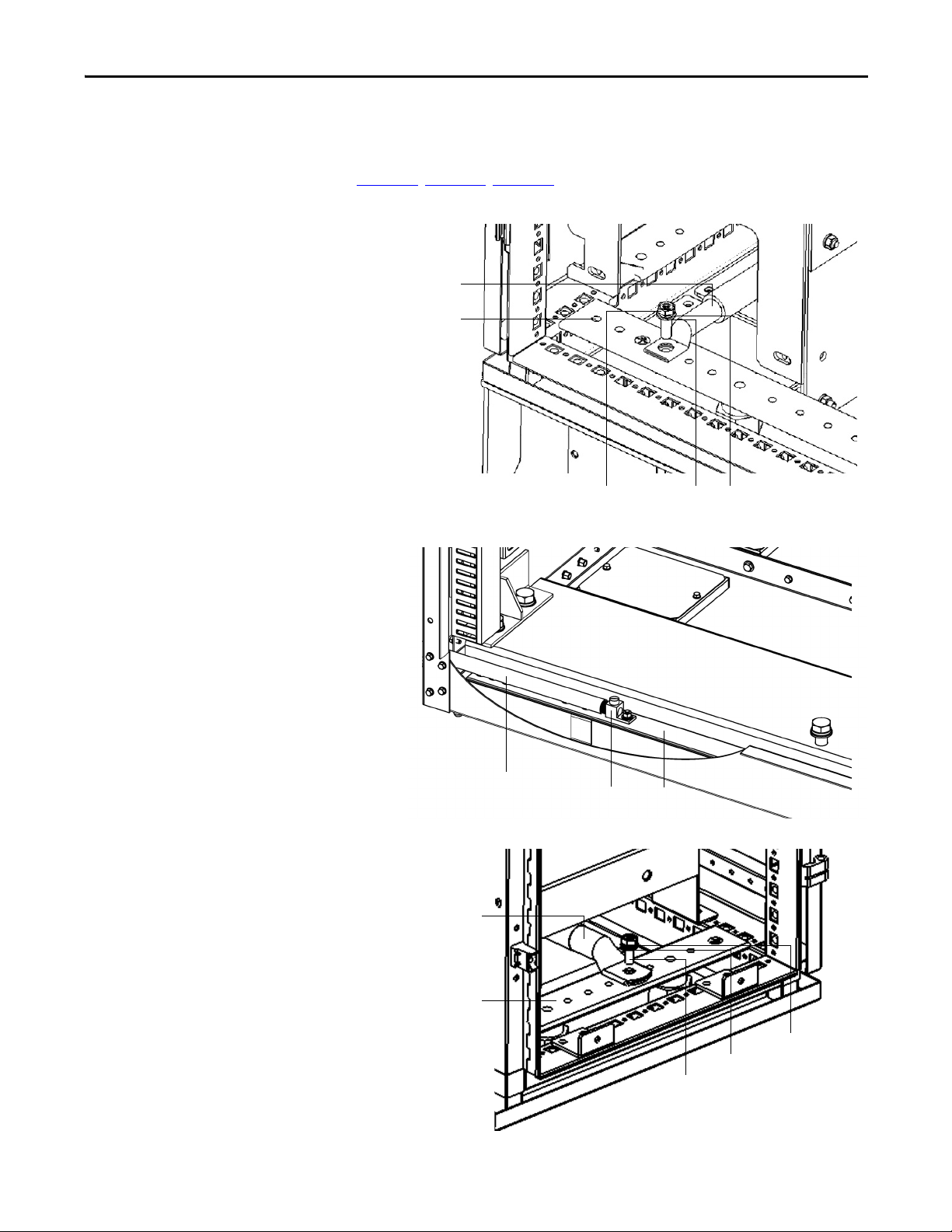
Customer/Contractor supplied
System Ground cable
Lock washerFlat washerM8x25 bolt
Ground Bus
Ter mi nal Box
Customer/Contractor supplied
System Ground cable
Ground Bus
Customer/Contractor supplied
System G round cable
Ground Bus
Lock washer
Flat washer
M8x25 bolt
Connect the System Ground Cable
The drive ground bus runs along the bottom of the drive at the front. The ground
bus is accessible at the bottom of the front of each drive cabinet when the cabinet
door is opened. Connect the system ground cable to the drive ground bus
(Figure 25
Figure 25 - Ground Cable Connection in the Isolation Transformer Cabinet, A-Frame
Figure 26 - Ground Cable Connection in the Isolation Transformer Cabinet, H-Frame
, Figure 26, Figure 27).
Figure 27 - Ground Cable Connection in the Isolation Transformer Cabinet, B-Frame
Rockwell Automation Publication 6000-IN006H-EN-P - October 2020 45
Page 46

Chapter 2 Drive Electrical Installation
IMPORTANT
IMPORTANT
IMPORTANT
If an optional cabinet is supplied, the system ground cable connection is in the
optional cabinet. See the PowerFlex 6000 Medium Voltage Variable Frequency
Drive User Manual, publication 6000-UM002
.
Insulation Resistance (IR) Test of Power Cables
Connect Incoming Line and Outgoing Motor Power Cables
Before connecting the incoming line and outgoing motor power cables, follow
standard industry practice to verify the integrity of the power cable insulation
from the input breaker to the drive and from the drive to the motor.
The installer must ensure that all power connections are in accordance with
national and local electrical codes.
Each drive is equipped with provisions for bottom power cable entry as standard.
Provisions for top power cable entry can also be provided. This must be specified
at the time of order.
For the location of incoming line and outgoing motor power cable connections,
refer to the customer-specific Dimension Drawing.
The drive is supplied with the following provisions for power cable lugs.
Table 6 - Power Terminals
Incoming Line Cable Connections L1 L2 L3
Outgoing Motor Cable Connections U V W
Connect Cables for A-Frame Drives
For A-Frame drives, Figure 28, shows typical connection points for the primary
entrance/exit cable.
If a filter cabinet is supplied, the incoming line cables are from Junction cabinet
and outgoing motor cable connections are in the filter cabinet (see Figure 29
See the PowerFlex 6000 Medium Voltage Variable Frequency Drive User
Manual, publication 6000-UM002
1. Connect the three-phase medium voltage inputs L1, L2, and L3 for top or
bottom entry to the user-provided input three-phase AC power.
Cable entry and exit cable holes should be sealed.
2. Connect three-phase medium voltage inputs U, V, and W for top or
bottom entry to the user-provided three-phase asynchronous motor.
3. Cable clamps are provided in the cabinet to aid in routing and supporting
the incoming line and outgoing motor power cables.
.
).
46 Rockwell Automation Publication 6000-IN006H-EN-P - October 2020
Page 47

Drive Electrical Installation Chapter 2
Removable barrier
Plastic M6x25 bolt, plastic nut,
and plastic washer (3)
Remove Barrier for Bottom Entry Connections
If you choose to connect the cables through the bottom entry of the A-Frame
drive, you have to remove the insulation barrier before you proceed.
1. Remove the three plastic M6x25 bolts that secure the removable insulation
barrier.
2. Pull out the removable barrier.
3. Connect the cables.
4. Install the removable barrier in the reverse order of removal.
Rockwell Automation Publication 6000-IN006H-EN-P - October 2020 47
Page 48

Chapter 2 Drive Electrical Installation
Side ViewFront View
Outgoing motor power
cable connections
Incoming line power
cable connections
Outgoing motor power
cable connections
Incoming line power
cable connections
Top entr y
Bottom entry
Top en try
Cable cl amp
Bottom entry
Top entry Bottom entry
Input
Shielded cable
Output
Non-shielded cable
OutputInput
Figure 28 - Isolation Transformer Cabinet, A-Frame (DV/DT cabinet not applied)
Figure 29 - Isolation Transformer Cabinet, A-Frame (DV/DT filter cabinet applied)
48 Rockwell Automation Publication 6000-IN006H-EN-P - October 2020
Page 49

Drive Electrical Installation Chapter 2
IMPORTANT
Isolation transformer
Cable clamp
Volt age S ensin g
Board
L1L2L3
U
V
W
Power cabl e
connections to
Power Modules
Incoming line power
cable connections
Outgoing motor power
cable connections
Connect Cables for H-Frame and B-Frame Drives
For H-Frame and B-Frame drives, Figure 30, Figure 31, and Figure 32 show typical
connection points for the primary entrance/exit cable.
If an optional cabinet is supplied, the incoming line and outgoing motor cable
connections are in the Bypass cabinet. See the PowerFlex 6000 Medium
Voltage Variable Frequency Drive User Manual, publication 6000-UM002
1. Connect the three-phase medium voltage inputs L1, L2, and L3 to the
user-provided input three-phase AC power.
2. Connect three-phase medium voltage inputs U, V, and W to the userprovided three-phase asynchronous motor.
3. Cable clamps are provided in the cabinet to aid in routing and supporting
the incoming line and outgoing motor power cables.
Figure 30 - Isolation Transformer Cabinet, H-Frame (Junction cabinet not applied)
.
Rockwell Automation Publication 6000-IN006H-EN-P - October 2020 49
Page 50

Chapter 2 Drive Electrical Installation
Cable cl amp
Volt age S ensin g
Board
Isolation Transformer
Door position
limit switches
L3 L2 L1 W V U
Incoming line power
cable connections
Outgoing motor power
cable connections
Power cabl e
connections to
Power Modu les
L3 L1
WV U
L2
Junction
cabinet
Incoming line
power cable
connections
Outgoing moto r
power cable
connections
Isolation
Transformer
Front View Side View
Figure 31 - Isolation Transformer Cabinet, B-Frame (Junction cabinet not applied)
Figure 32 - Isolation Transformer Cabinet, B-Frame (Junction cabinet applied for cable
connection)
50 Rockwell Automation Publication 6000-IN006H-EN-P - October 2020
Page 51
Drive Electrical Installation Chapter 2
Cable entrance in top
of LV Control Cabinet
Wire d uct fo r
bundling cable
Bracket for
bundling cable
Cable entrance in bottom
of LV Control Cabinet
Cable entrance in bottom
rear of LV Co ntrol Cabinet
Bottom Entry Design
Cable entrance in top
of LV Control Cabinet
Top Entry Design
Connect Control Power Wiring
Introduction
Externally supplied control power is required to operate the drive. The standard
voltage that is supported is 220V AC/50 Hz. The other typical phase voltages of
230V AC, 110V AC, and 120V AC are also supported (50/60 Hz), but must be
specified at the time of order. A minimum of 3 kVA is required to supply the
control circuit.
Wiring Routing and Connection
The opening for the control power wiring must be specified during the quotation
stage. See the customer-specific Dimension Drawing for the location of the
opening. The typical top/bottom entry design is shown below (Figure 34
Figure 33 - Control Power Wiring Opening, A-Frame
).
Figure 34 - Control Power Wiring Opening, H-Frame
Rockwell Automation Publication 6000-IN006H-EN-P - October 2020 51
Page 52

Chapter 2 Drive Electrical Installation
Cable entrance in
top or bottom front
of LV Control Cabinet
DTB1 Ter minal
Block strip
DTB2 Terminal
Block strip
Figure 35 - Control Power Wiring Opening, B-Frame
The control power wiring terminates to the DTB1 terminal block strip on the
left side of the LV Control cabinet (Figure 36
general overview. See Electrical Drawings for actual connection points.
Figure 36 - Terminal Block Strip locations
). See Figure 45 or Figure 46 for
52 Rockwell Automation Publication 6000-IN006H-EN-P - October 2020
Page 53

Drive Electrical Installation Chapter 2
Connect External Control Signal Wiring
Introduction
This section summarizes the control signal wiring from the remote DCS/PLC or
discrete control to the drive. General connections are detailed in Power Cabling
and Control Signal Wiring Details on page 73. Refer to the Electrical Drawings
for connection information specific See the drive being installed.
Analog and Digital I/O Overview
Four 4...20 mA analog input signals. One may be used for DCS with rotating
speed setting and three for backup. For detailed information, see Tab l e 1 5
Table 16 on page 76
Two 4...20 mA analog output signals for indication signals such as output motor
current and frequency. See Ta b l e 1 5
Sixteen passive dry contact inputs (internal 24V DC power supply) start/stop
and reset controls. For detailed information, see Ta b l e 1 5
page 76. These inputs are scalable depending on user requirements.
Twenty dry contact outputs: including nine active dry contact outputs with a
capacity of not more than 20W for indication (backup), and 11 passive dry
contact outputs powered by the drive with a capacity of 220V AC/5A for DCS
status/fault indication. For detailed information, see Ta b l e 1 5
page 76. These outputs are scalable depending on user requirements.
.
and Table 16 on page 76.
and Table 16 on
and Table 16 on
and
The drive is provided with dry contact outputs (1 N.O. with a capacity of
220V AC/5 A, valid when closed) which trigger the user-provided medium
voltage circuit breaker for interlock with the user-provided medium voltage
switch cabinet. For detailed information, see Ta b l e 1 5
Modbus RTU interface is supplied as standard (other communication interfaces
including Modbus TCP, Modbus Plus, EtherNet/IP™, and PROFIBUS are
provided as options). For detailed information, see Figure 46 on page 75
and Table 16 on page 76.
.
Wiring Routing and Connection
The control signal wiring enters the drive through the same opening as the
control power wiring in the LV Control Cabinet (Figure 34
The wiring terminates either to the DTB1 or DTB2 terminal block strips on
either side of the LV Control cabinet (Figure 36
general information. See Electrical Drawings for actual connection points.
). See Figure 45 or Figure 46 for
or Figure 35).
Rockwell Automation Publication 6000-IN006H-EN-P - October 2020 53
Page 54

Chapter 2 Drive Electrical Installation
Door Position Limit Switch
Connect Electrical Safety Interlock Circuit to Input Circuit Breaker
Introduction
The electrical safety interlock circuit is part of the overall control signal wiring
activity. However, it is mentioned separately in this document due to its critical
importance related to the safe operation of the drive and personnel safety.
The circuits that are connected between the drive and the input circuit breaker:
• allow the drive to trip the input circuit breaker if a drive cabinet door is
opened. This applies to the cabinet doors where medium voltage is
present. The LV Control cabinet door can be opened while the drive is
energized.
• allow the drive to prevent the input circuit breaker from closing when
required.
• indicate to the drive when the input circuit breaker is closed.
MV Door Safety Interlock
If the MV cabinet door is opened, the Allen-Bradley Guardmaster® Limit Switch
(440P-CRPS11D4B) on the cabinet door will actuate. The drive will send a trip
signal to the input circuit breaker to disconnect the medium voltage power
supply to the drive.
ATT EN TI ON : The door position interlock is a safety feature. It must not be used
solely as a part of the plant operation process to ensure that the drive has been
disconnected from input medium voltage. Keep the medium voltage doors
locked as standard practice. Always go to the input circuit breaker feeding the
drive to verify if it is open. Lock out and tagout the input circuit breaker before
performing any work on the drive or bypass units.
Figure 37 - Interlock for Cabinet Doors
54 Rockwell Automation Publication 6000-IN006H-EN-P - October 2020
Page 55

Drive Electrical Installation Chapter 2
When the doors of the Power Module/LV Control Cabinet or Isolation
Transformer Cabinet are not closed, when the drive is being maintained or when
the control power switch is not closed, the drive will not send a signal allowing
the input circuit breaker to close; this is wired as a permissive contact in the input
circuit breaker’s closing circuit so that the input circuit breaker cannot close.
Wire Routing and Connection
The electrical safety interlock control signal wiring enters the drive through the
same opening as the control power wiring in the bottom of the LV Control
Cabinet (Figure 34
The wiring terminates to the X1 terminal block strip on the right side of the LV
Control cabinet (Figure 36
See Electrical Drawings for actual connection points.
or Figure 35).
). See Figure 45 or Figure 46 for general information.
Rockwell Automation Publication 6000-IN006H-EN-P - October 2020 55
Page 56

Chapter 2 Drive Electrical Installation
Notes:
56 Rockwell Automation Publication 6000-IN006H-EN-P - October 2020
Page 57

Drive Electrical Interconnection
Chapter 3
Introduction
Electrical Interconnection Summary
Power Cable Interconnection Overview
The drive is shipped in two sections, the Isolation Transformer cabinet and the
Power Module/LV Control cabinet. An optional cabinet may also be supplied.
Drive Mechanical Installation
cabinets together. This chapter describes the activities that are required to
electrically connect these drive cabinets’ components together.
Connect Internal Cabling and Wiring Page
Connect Isolation Transformer Secondary Power Cables 58
Connect Motor and Voltage Sensing Board Cables 61
Connect LV Control and Fan Wiring Bundles 62
Connect Ground Bus 62
Figure 38 provides a three-line drawing overview of the power cable
interconnections between the power modules (PC XX) in the Power Module/
LV Control cabinet and the secondary windings of the isolation transformer in
the Isolation Transformer cabinet. The number of power modules is dependent
solely on output (motor) voltage:
• 9 power modules for 2.3/2.4/3.0/3.3 kV
• 12 power modules for 4.0/4.16 kV
• 15 power modules for 6.0 kV
• 18 power modules for 6.6/6.9 kV
• 24 power modules for 10 kV
• 27 power modules for 11 kV
on page 11 describes mechanically joining these
It also shows the connection point from the U, V, and W motor output phases
from the power module array to the voltage sensing board cables and the motor
cables.
The isolation transformer secondary windings as shown do reflect the actual
orientation on the isolation transformer.
The Power Module/LV Cabinet orientation is optimized for drawing clarity. To
better understand the physical orientation, the components and connections that
are shown in the Power Module/LV Control Cabinet would be rotated 90º
counter clockwise. The U phase is the top horizontal row, the V phase is the
middle horizontal row, and the W phase is the bottom horizontal row.
Rockwell Automation Publication 6000-IN006H-EN-P - October 2020 57
Page 58

Chapter 3 Drive Electrical Interconnection
L1
L2
L3
1U
1V
1W
2U
2V
2W
3U
3V
3W
4U
4V
4W
5U
5V
5W
6U
6V
6W
7U
7V
7W
8U
8V
8W
9U
9V
9W
U
V
W
PC A1
PC A2
PC A3
PC B1
PC B2
PC B3
PC C1
PC C2
PC C3
U
V
W
Input power
3-phase AC
any voltage
Isolation Transformer
Motor
Volt age Sens ing
Board
Isolation Transformer Cabinet Power Module/LV Control Cabinet
See the Electrical Drawing for actual wire number designations.
Figure 38 - Power Cabling Overview (3.3 kV shown)
Connect Isolation
Introduction
Transformer Secondary
Power Cables
58 Rockwell Automation Publication 6000-IN006H-EN-P - October 2020
The isolation transformer’s three-phase primary coils are oriented A, B, and C
from left to right, as viewed from the front. The secondary windings are also
divided into three principal sections from top to bottom. The upper third are to
feed the power modules in the U output phase. The middle third are to feed the
power modules in the V output phase. The bottom third are to feed the power
modules in the W output phase (Figure 39
).
Page 59

Drive Electrical Interconnec tion Chapter 3
PRIMARY WINDING INPUT
SECONDARY WINDING OUTPUT
A (L1) B (L2) C (L3)
U
V
W
SECONDARY WINDING OUTPUT
U
V
W
Figure 39 - Isolation Transformer Primary and Secondary Winding Orientation
The secondary windings are brought out to corresponding vertical isolated standoffs on the body of the transformer (orientated U, V, and W from left to right as
viewed from the front). See Figure 40
.
Each secondary winding set will have a designated U, V, and W terminal
connection. For example, (from top to bottom and left to right) the terminals
from the first winding set are 1W, 1V, and 1U, the terminals from the next
winding set are 2W, 2V, and 2U, and so on.
As shown in Figure 38
, the first winding set (1U, 1V, and 1W) will connect to the
three-phase input power connection of the first power module in the U motor
phase array (PCA1), the second winding set will connect to the second power
module in the U motor phase array (PCA2), and the third winding set will
connect to the third power module in the U motor phase array (PCA3). The
next three winding sets connect to the power modules in the V motor phase array.
The remaining three winding sets connect to the power modules in the W motor
phase array.
Figure 38
shows 3.0/3.3 kV configuration. The 6.0/6.6 kV and 10 kV
configuration have more power modules and therefore have more corresponding
isolation transformer secondary windings. The concept is the same—the top
third of the winding sets feeds the power modules in the U phase, the middle
third feeds the power modules in the V phase, and the bottom third feeds the
power modules in the W phase.
Rockwell Automation Publication 6000-IN006H-EN-P - October 2020 59
Page 60

Chapter 3 Drive Electrical Interconnection
M8 Hex Nut M8 Flange Nut
(1-n) U
Secondary Winding Connections
1U
Power Cable to Power Module
Front View
(1-n) V
Secondary Winding Connections
(1-n) W
Secondary Winding Connections
2U
3U
4U
5U
6U
Each three-phase secondary winding set of the isolation transformer has three
individual single-phase power cables connecting its output to the three-phase
power input of its corresponding power module.
Drives are shipped split with an Isolation Transformer cabinet and a Power
Module cabinet, and connection at the site is needed. The power cables connect
to the secondary winding termination in the Isolation Transformer. All cables can
be connected from the front of the cabinet.
Cable Routing and Connection
Figure 40 - 6.0/6.6 kV Power Module Configuration
60 Rockwell Automation Publication 6000-IN006H-EN-P - October 2020
Page 61

Drive Electrical Interconnec tion Chapter 3
U Phase
V Phase
W Phase
Motor cable
to Junction
cabinet
M6x16 bolt
VSB cable
Front View
Connect Motor and Voltage Sensing Board Cables
Introduction
The Voltage Sensing Board cables and the motor cables both connect to the same
output point of each motor phase array (Figure 38
must be connected on site.
For drive ratings with power modules ≥250 A, the connection points are always
on the right side of the power module cabinet. For drive ratings with power
modules ≤200 A, the connection points are on the left side of the power module
cabinet.
A typical connection with connection points on the left side of the power
module cabinet are shown in the following diagrams (Figure 41
Figure 41 - 4.16 kV Power Module Configuration – A-Frame
). The voltage sensing cables
, Figure 42).
Rockwell Automation Publication 6000-IN006H-EN-P - October 2020 61
Page 62
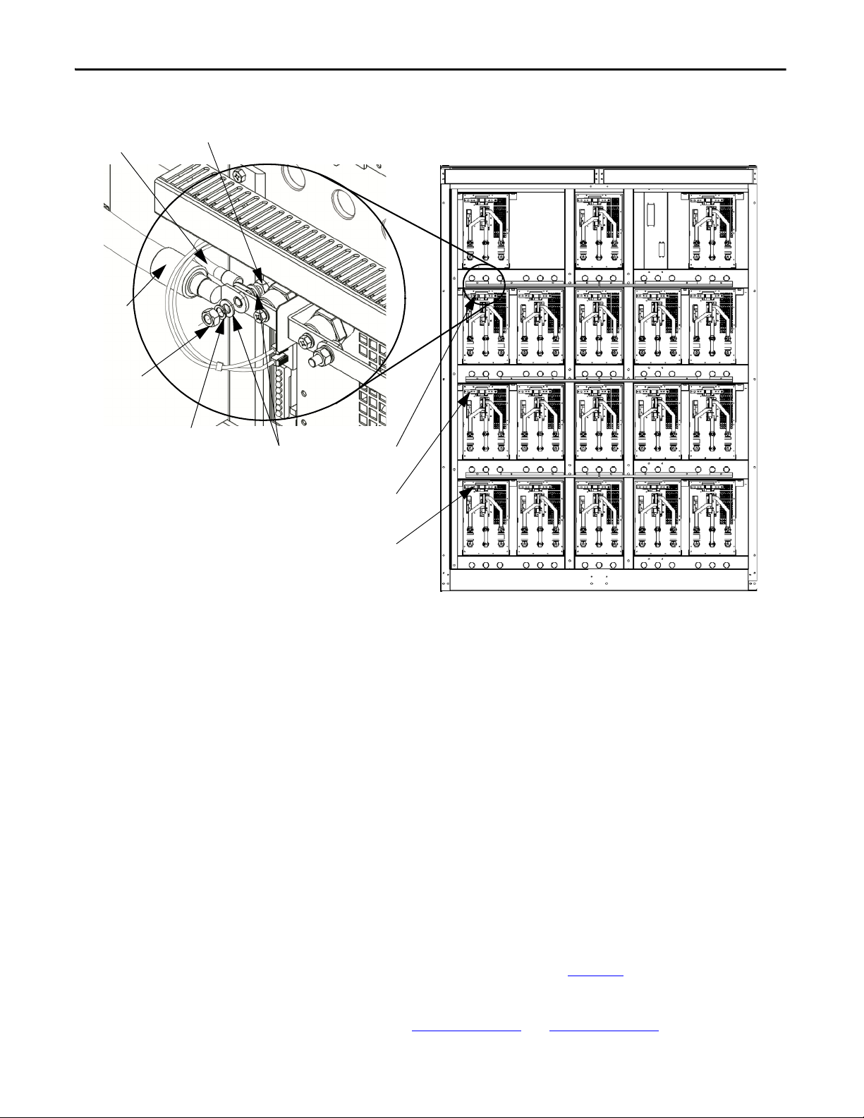
Chapter 3 Drive Electrical Interconnection
Hex nut
Flat washer
Lock wash er
Hex bolt
Motor cable
VSB cable
U Phase
V Phase
W Phase
Front View
Figure 42 - 6.6/6.9 kV Power Module Configuration – H-Frame and B-Frame
Connect LV Control and Fan Wiring Bundles
Connect Ground Bus
Introduction
There are control wiring bundles that must be reconnected after the drive
cabinets are connected together. These control wiring bundles are connected for
the factory test and then disconnected and bundled at the shipping splits before
shipment.
For exact wire numbers and terminal block designations, refer to the Electrical
Drawings.
Introduction
A solid ground bus is located at the bottom front of each cabinet. When a
shipping split is required, ground bus connectors are supplied. One is attached
above the solid ground bus and one below (Figure 43
Ground bus connection openings are provided in the cabinet sidesheets for this
connection. See Table 1 on page 14
and Tab le 2 on pag e 1 5.
).
62 Rockwell Automation Publication 6000-IN006H-EN-P - October 2020
Page 63
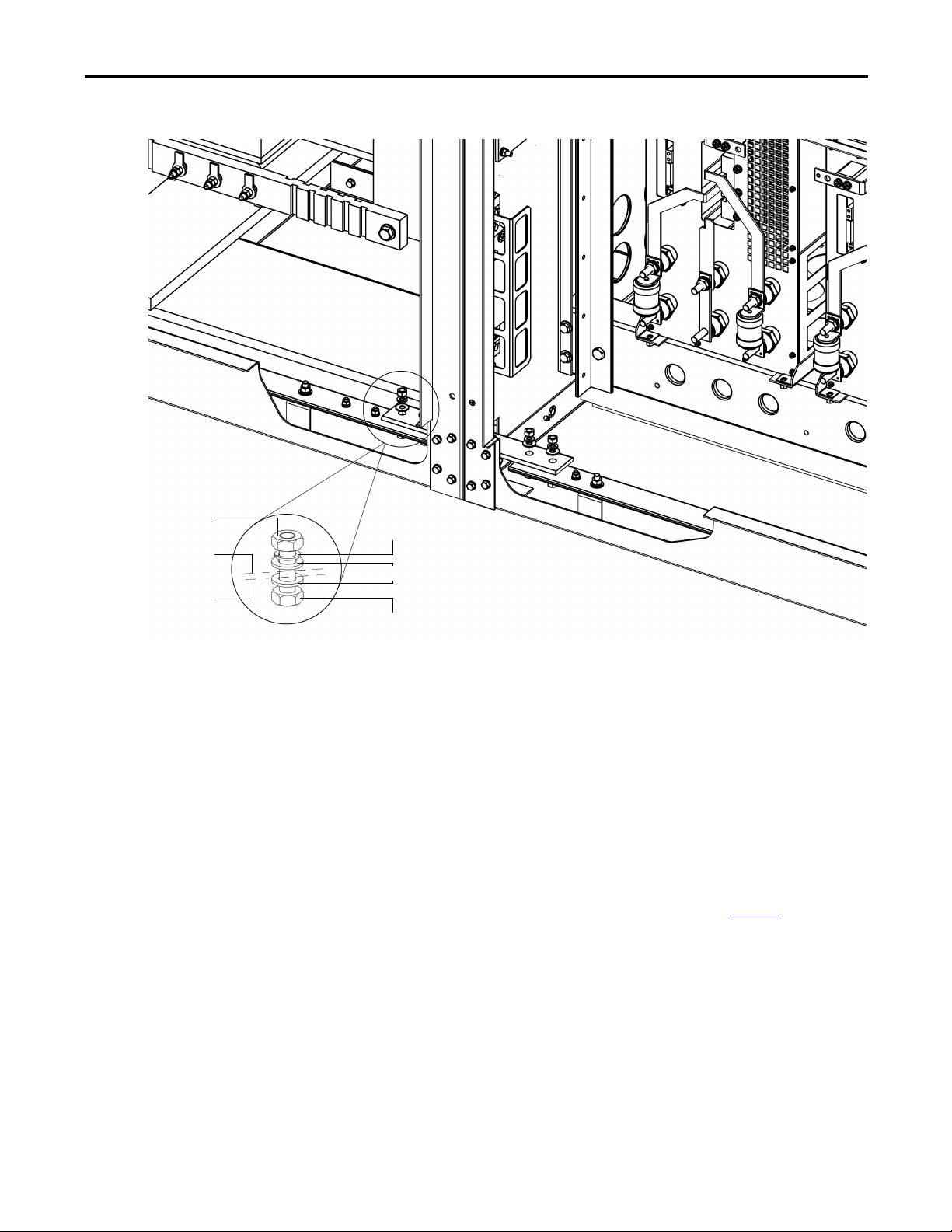
Figure 43 - Interconnection Ground
M8 Hex Nut
Lock Wash er
Flat Washer
M8x30 Hex Bolt
Grounding Bus
Connecto r
Grounding
Bus
Drive Electrical Interconnec tion Chapter 3
Complete the Installation
1. Inspect the interior of all cabinets carefully for hardware or tools that may
have been misplaced.
2. Check and verify that no hardware or foreign material has fallen in the
secondary windings in the Isolation Transformer cabinet.
3. Check that all mechanical work has been completed properly. All barriers
and guards that may have been removed must be reinstalled.
4. Check that all electrical connections have been made and torqued as
specified.
5. Verify that the safety circuit is working properly (see page 54
6. Reinstall all cabinet back plates.
Rockwell Automation Publication 6000-IN006H-EN-P - October 2020 63
).
Page 64

Chapter 3 Drive Electrical Interconnection
Notes:
64 Rockwell Automation Publication 6000-IN006H-EN-P - October 2020
Page 65

Pre-Commissioning
IMPORTANT
Appendix A
Pre-Commissioning Responsibilities
Rockwell Automation manages the startup service for each installed drive at the
customer’s site, but there are a number of tasks the customer or its representatives
must complete before scheduling Rockwell Automation personnel for drive
commissioning.
Review this information before commissioning the drive as a reference for drive
line-up commissioning. Record the information in the data sheets provided;
these are useful during future maintenance and troubleshooting exercises.
ATT EN TI ON : Perform the pre-commissioning tasks in the order listed in this
chapter. Failure to do so may result in equipment failure or personal injury.
Rockwell Automation requests a minimum of four weeks’ notice to schedule
each startup.
Inspection and Verification
Before the drive commissioning occurs, Rockwell Automation recommends that
the customer arranges a pre-installation meeting to review:
a. the startup plan
b. the startup schedule
c. the drives installation requirements
d. the pre-commissioning checklist
Customer personnel must be on-site to participate in the system startup
procedures.
See Safety and Codes
ATT EN TI ON : The CMOS devices that are used on the control circuit boards are
susceptible to damage or destruction by static charges. Personnel working near
static sensitive devices must be appropriately grounded.
Rockwell Automation Publication 6000-IN006H-EN-P - October 2020 65
on page 39.
Page 66

Appendix A Pre-Commissioning
Pre-Commissioning Checklist
Once all points of the checklist are complete, initial each checkbox and provide
the date. Photocopy the checklist and fax the copy to the Rockwell Automation
Startup Manager, along with the planned startup date. Upon receiving this
checklist, the Project Manager will contact the site to finalize arrangements for a
startup engineer to travel to the site at your convenience.
Print the following information:
Name: Date:
Compan y:
Phone: Pages:
Fax:
Drive Serial Number:
Rockwell Automation Service Engineer Requested (YES/NO):
Scheduled Commissioning Date:
Table 7 - Receiving and Unpacking:
Initials Date Check
The drives have been checked for shipping damage upon receiving.
After unpacking, the items received are verified against the bill of materials.
Any claims for breakage or damage, whether concealed or obvious, are made to
the carrier by the customer as soon as possible after receipt of shipment.
All packing material, wedges, or braces are removed from the drive.
Table 8 - Installation and Mounting:
Initials Date Check
The drive is securely fastened in an upright position, on a level surface.
The Isolation Transformer Cabinet, Power Module Cabinet, and Bypass Cabinet (if
applicable) are correctly installed.
Lifting Angles have been removed.
Bolts are inserted into original location on top of drive (help prevent leakage of
cooling air).
All contactors and relays have been operated manually to verify free movement.
The back plates to the cabinets have been reinstalled.
Table 9 - Safety:
Initials Date Check
The grounding of the drive should be in accordance with national and local
electrical codes.
66 Rockwell Automation Publication 6000-IN006H-EN-P - October 2020
Page 67

Table 10 - Control Wiring:
Initials Date Check
Table 11 - Power Wiring:
Initials Date Check
Pre-Commissioning Appendix A
All low voltage wiring entering the drive is labeled, appropriate wiring diagrams
are available, and all customer interconnections are complete.
All AC and DC circuits are run in separate conduits.
All wire sizes that are used are selected by observing all applicable safety and
national and local electrical codes.
Remote I/O is correctly installed and configured (if applicable).
All 3-phase control wiring is within specified levels and has been verified for
proper rotation, UVW.
All single-phase control wiring is within specified levels and has grounded
neutrals.
Control lines must be shielded and grounded. Control and Power lines must run
in separate conduits.
The electrical safety interlock wiring to input circuit breaker is correctly
installed.
The power cable connections to the drive, motor, and isolation transformer
adhere to national and local elec trical codes.
The cable terminations, if stress cones are used, adhere to the appropriate
standards.
Appropriate cable insulation levels are adhered to, as per Rockwell Automation
specifications.
All shields for shielded cables must be grounded at the source end only.
If shielded cables are spliced, the shield must remain continuous and insulated
from ground.
All wire sizes that are used are selected by observing all applicable safety and
national and local electrical codes.
All power connections are torqued as per Rockwell Automation specifications.
Refer to Tor que Requ ire me nts
All customer power cabling has been insulation resistance (IR) tested or hi-pot
tested before connecting to drive system.
Power wiring phase rotation has been verified per the specific electrical
diagrams that are supplied by Rockwell Automation.
on page 69.
Table 12 - Interconnection Wiring
Initials Date Check
The power cable connection between the Isolation Transformer and Power
Modules.
The motor cable connection to the three output buses.
The Voltage Sensing Board connections to the three output buses.
All low voltage connections to the Isolation Transformer Low Voltage panel.
Rockwell Automation Publication 6000-IN006H-EN-P - October 2020 67
Page 68

Appendix A Pre-Commissioning
Table 13 - Drive Line-up Status
Initials Date Check
The medium voltage and low voltage power is available for startup activities.
The motor is uncoupled from the driven load.
The load is available for full load testing.
68 Rockwell Automation Publication 6000-IN006H-EN-P - October 2020
Page 69

Torque Requirements
Appendix B
Torque Requirements
Proper tightening torque must be used for installation and wiring.
Table 14 - Torque Requirements
Tor que
Thread Size
M4 3.0 2.2
M5 5.9 4.4
M6 10.5 7.7
M8 26.0 19.2
M10 51.0 37.6
M12 89.0 65.7
M14 141.0 104.1
M16 215.0 158.7
M20 420.0 310.0
Class 8.8
N•m lb•ft
Rockwell Automation Publication 6000-IN006H-EN-P - October 2020 69
Page 70

Appendix B To rqu e Re qu ire men ts
Notes:
70 Rockwell Automation Publication 6000-IN006H-EN-P - October 2020
Page 71

General Wire Categories
Appendix C
General Wire Categories
Conductors
Category
Power Supplies 1 AC power supply
Control 2
To P LC 4
(1) 18 AWG, twisted-pair, shielded
(2) 18 AWG, 3 conductor, shielded
(3) 18 AWG, twisted-pair, shielded
(4) 24 AWG, twisted-pair, shielded
Conductors
Group
3
5 Digital circuit
Machine With Signal Examples Recommended
(TO 600V AC)
220V AC or
220V DC Logic
24V AC or
24V DC logic
Analog Signal
DC supply
(high speed)
Cable
220V, 1Ø Per IEC / NEC,
Local codes and
application
requirem ents
Relay Logic PLC I/O
PLC I/O Per IEC / NEC,
5...24V DC Supplies
Pulse train input
tachometer PLC
communication
Per IE C / NEC,
Local codes and
application
requirem ents
Local codes and
application
requirem ents
Belden 8760
Belden 8770
Belden 9460
Belden 8760
Belden 9460
Belden 9463
Conductors
Group
Tra y
Tra y
Tra y
All signal wiring must be run in separate steel
(1)
conduit.
(2)
(3)
A wire tray is not suitable.
(1)
The minimum spacing between conduits
(3)
containing different wire groups is 76.2 mm
(3 in.).
(4)
Power
Supplies
mm (in.)
228.6 (9.00) 152.4 (6.00)
228.6 (9.00) 152.4 (6.00)
228.6 (9.00) 152.4 (6.00)
Control
mm (in.)
To P LC
All signal wiring must be run
in separate steel conduit.
A wire tray is not suitable.
The minimum spacing
between conduits containing
different wire groups is
76.2 mm (3 in.).
Rockwell Automation Publication 6000-IN006H-EN-P - October 2020 71
Page 72

Appendix C General Wire Categories
Notes:
72 Rockwell Automation Publication 6000-IN006H-EN-P - October 2020
Page 73

Appendix D
DANGER :
The medium voltage drive is one component in this system, which includes an input device that is supplied by others.
The supplier of the input device is responsible for confirming that there is safe access to the input/output drive (if used) and safe access to the drive.
MFN1
Customer Supplied
Ground
4.16 kV, 3 phase, 60 Hz
Upstream Circuit Breaker
(Customer scope of supply)
To M oto r
Control Signal
110/120/220/230/240V AC, 1 phase, 50/60 Hz.
Control Signal with Branch Circuit Protection
(Minimum 3 kVA Capacity is needed)
Power Cabling and Control Signal Wiring Details
Schematic Diagrams
Figure 44 - Schematic Diagram of the Drive System without a Bypass Cabinet, A-Frame
(1)
(1) Wiring locations are for design reference only; actual wiring must comply with the drawings that are provided with the drive.
Rockwell Automation Publication 6000-IN006H-EN-P - October 2020 73
Page 74

Appendix D Power Cabling and Control Signal Wiring Details
/// :98
'7%
'7%
/
1
$$$
3(*5'
MFN1 MFN3 MFN4
Customer Supplied
Ground
13.8 kV, 3 phase, 60 Hz
Upstrea m Circuit Breaker
(Customer scope of supply)
To M oto r
Control Si gnal
DANG ER:
The medium voltage drive is one component in this system, which includes an input device that is supplied by others.
The supplier of the input device is responsible for confirming that there is safe access to the input/output drive (if used) and safe access to the drive.
110/120/220/230/240V AC, 1 phase, 50/60 Hz.
Control Signal wi th Branch Circuit Protection
(Minimum 3 kVA Capacity is needed)
MFN2 MFN5 MFN6
Figure 45 - Schematic Diagram of the Drive System without a Bypass Cabinet, H-Frame
(1)
(1) Wiring locations are for design reference only; actual wiring must comply with the drawings that are provided with the drive.
74 Rockwell Automation Publication 6000-IN006H-EN-P - October 2020
Page 75

Power Cabling and Control Signal Wiring Details Appendix D
$
$
$
/
1
'7%
'7%
%
'&'
5;' 7;'
*1' 576 &76
$
$
$
$
$
$
$
$
$
a
L 120V AC
From
Customer
To R em ote DC S
(Reserved)
NOTE:
1. 4...20 mA shielded cable from customer input shall be grounded at the inverter side.
2. Remote DI input to drive shall be of pulse type with a duration of three seconds, shielded cable.
3. Connection that is marked with dotted line shall be in the customer’s scope of supply.
From CB (or
vacuum contactor)
To R em ote DC S
To C B
To C ust om er
Vacu um Con tacto r
(Reserved)
E-Stop Status
(Reserved)
N0V AC
MV Closed
MV Pre-Closed CB
MV Closed
Warn in g
Faul t
Drive Running
Drive Stop
Ready
Remote DCS Control
MV Pre-Closed CB
MV Closed
Warn in g
Faul t
Drive Running
Drive Stop
Ready
Remote DCS Control
Pre-Closed CB (N.O.)
CB Open (N.O.)
Pre-Closed CB (N.C.)
(Reserved)
CB Open (N.C.)
(Reserved)
MV Close (N.O.)
(Reserved)
Emergency Stop
From Remote
Reserved
Reserved
Reserved
Reserved
Reserved
Reserved
Reserved
Reserved
+24V DC
Remote DCS
Fault Reset
Reserved
Reserved
Reserved
Remote Start
Remote Stop
To R em ote
From Remote
MODBUS / RS-485
Current Output
4...20 mA
Frequency O utput
4...20 mA
Speed Input
4...20 mA
Analog Input
4...20 mA (Reserved)
Analog Input
4...20 mA (Reserved)
From Remote DCS
E-Stop Status
(Reserved)
Figure 46 - Terminal Strip Wiring Diagram for Drive System without a Bypass Cabinet
Rockwell Automation Publication 6000-IN006H-EN-P - October 2020 75
Page 76

Appendix D Power Cabling and Control Signal Wiring Details
Standard Input/Output Connection Points
Table 15 - Standard I/O Connections Points
Serial Number Name of I/O Connection AI AO DI DO Note
1 Input circuit breaker closing node is allowed
(917, 918)
Input circuit breaker closing node is allowed
(957, 958) (Reserved)
2 Trip connection points within the VFD
(919, 920)
Trip connection points within the VFD
(959, 960) (Reserved)
3 Input circuit breaker already closed
connection point (117, 119)
4 Input vacuum contactor close (961, 962)
(Reserved)
5 Emergency stop status to Input vacuum
contactor (967,968)(Reserved)
Emergency stop status to Input vacuum
contactor (967,968)(Reserved)
1 Serially connected into the input circuit breaker's closing circuit
1 Serially connected into the input circuit breaker's closing circuit
1 Can be connected into input circuit breaker's closing circuit in parallel
1 Can be connected into input circuit breaker's closing circuit
1 Circuit breaker's auxiliary normally open connection points (valid when closed)
1 Serially connected into the vacuum contactor close
1 Serially connected into the vacuum contactor
1 Serially connected into the vacuum contactor
(the VFD provides passive normally open points, valid when closed)
(the VFD provides passive normally closed points, valid when open)
(the VFD provides passive normally open points, valid when closed)
(the VFD provides passive normally closed points, valid when open)
(the VFD provides passive normally open points, valid when closed)
(the VFD provides passive normally closed points, valid when open)
(the VFD provides passive normally closed points, valid when open)
Table 16 - I/O Connections related to Remote Distributed Control System
Serial Number Name of I/O Connection AI AO DI DO Note
1 VFD speed regulation command (931, 931A) 1 User-provided 4...20mA
Reserved (932, 932A) 1 User-provided 4...20 mA (Reserved)
Reserved (934, 934A) 1 User-provided 4...20 mA (Reserved)
2 VFD speed feedback signal (927, 928) 1 VFD-provided 4...20mA
3 VFD current feedback signal (925, 926) 1 VFD-provided 4...20mA
4 Alternate start command signal (431, 401)
(Reserved)
Remote DCS start command signal (449,
401)
Alternate command signal (432, 401)
(Reserved)
5 Remote DCS stop command signal (450, 401) 1 User-provided normally closed passive dry contact
6 Reserved (433, 401) 1 User-provided normally open passive dry contact
7 Reserved (434, 401) 1 User-provided normally open passive dry contact
8 Reserved (435, 401) 1 User-provided normally open passive dry contact (switch quantity)
Reserved (436, 401) 1 User-provided normally open passive dry contact (switch quantity)
Reserved (437, 401) 1 User-provided normally open passive dry contact (switch quantity)
Reserved (438, 401) 1 User-provided normally open passive dry contact (switch quantity)
9 Remote DCS alternate (448, 401) 1 User-provided normally open passive dry contact (switch quantity)
10 Remote DCS fault reset command (412, 401) 1 User-provided normally open passive dry contact
1 User-provided normally open passive dry contact
(pulsed quantity, valid with 3S)
1 User-provided normally open passive dry contact
(pulsed quantity, valid with 3S)
1 User-provided normally closed passive dry contact
(pulsed quantity, valid with 3S)
(pulsed quantity, valid with 3S)
(pulsed quantity, valid with 3S)
(pulsed quantity, valid with 3S)
76 Rockwell Automation Publication 6000-IN006H-EN-P - October 2020
Page 77

Power Cabling and Control Signal Wiring Details Appendix D
Table 16 - I/O Connections related to Remote Distributed Control System (Continued)
Serial Number Name of I/O Connection AI AO DI DO Note
Alternate reset command (412, 401) 1 User-provided normally open passive dry contact
11 Emergency stop button command
(1101, 1102)
Emergency stop button command
(1103, 1104)
12 VFD allow closing indication (901, 902) 1 VFD-provided normally open passive dry contact
Circuit breaker closing indication (903, 904) 1 VFD-provided normally open passive dry contact
VFD alarm indication (905, 906) 1 VFD-provided normally open passive dry contact
VFD fault indication (907, 908) 1 VFD-provided normally open passive dry contact
VFD operation indication (909, 910) 1 VFD-provided normally open passive dry contact
VFD stop indication (911, 912) 1 VFD-provided normally closed passive dry contact
VFD ready indication (913, 914) 1 VFD-provided normally open passive dry contact
Remote control indication (915, 916) 1 VFD-provided normally open passive dry contact
13 VFD allow closing indication (941, 941A) 1 VFD-provided normally closed passive dry contact
Circuit breaker closing indication (942, 942A) 1 VFD-provided normally closed passive dry contact
VFD alarm indication (943,943A) 1 VFD-provided normally closed passive dry contact
VFD fault indication (944, 944A) 1 VFD-provided normally closed passive dry contact
VFD operation indication (945, 945A) 1 VFD-provided normally closed passive dry contact
VFD stop indication (946, 946A) 1 VFD-provided normally open passive dry contact
VFD ready indication (947, 947A) 1 VFD-provided normally closed passive dry contact
Remote control indication (948, 948A) 1 VFD-provided normally closed active dry contact
1 User-provided normally closed passive dry contact
(voltage class higher than 220V AC, 5 A, switch quantity)
1 User-provided normally closed passive dry contact
(voltage class higher than 220V AC, 5 A, switch quantity)
(voltage class ≤220V AC, 5 A) (used for Remote DCS)
(voltage class ≤220V AC, 5 A) (used for Remote DCS)
(voltage class ≤220V AC, 5 A) (used for Remote DCS)
(voltage class ≤220V AC, 5 A) (used for Remote DCS)
(voltage class ≤220V AC, 5 A) (used for Remote DCS)
(voltage class ≤220V AC, 5 A) (used for Remote DCS)
(voltage class ≤220V AC, 5 A) (used for Remote DCS)
(voltage class ≤220V AC, 5 A) (used for Remote DCS)
(voltage class ≤220V AC, 5 A) (used for Remote DCS)
(voltage class ≤220V AC, 5 A) (used for Remote DCS)
(voltage class ≤220V AC, 5 A) (used for Remote DCS)
(voltage class ≤220V AC, 5 A) (used for Remote DCS)
(voltage class ≤220V AC, 5 A) (used for Remote DCS)
(voltage class ≤220V AC, 5 A) (used for Remote DCS)
(voltage class ≤220V AC, 5 A) (used for Remote DCS)
(voltage class ≤220V AC, 5 A) (used for Remote DCS)
Rockwell Automation Publication 6000-IN006H-EN-P - October 2020 77
Page 78

Appendix D Power Cabling and Control Signal Wiring Details
Notes:
78 Rockwell Automation Publication 6000-IN006H-EN-P - October 2020
Page 79

Appendix E
Line and Load Cable Sizes
The data in the following tables are informative only; do not base final design
criteria solely on this data. Follow national and local installation codes, industry
best practices, and cable manufacturer recommendations. As cabling methods
can vary widely, maximum cables sizes do not account for the size of the conduit
hub.
Table 17 - Line and Load Cable Sizes for A-Frame Drives (IEC)
Description
(Motor V/Freq.)
Maximum Line
Cable Sizes
Maximum Load
Cable Sizes
(1) Cable sizes are based on overall dimensions of compact-stranded three-conductor shielded cable (common for industrial cable tray
installations). Maximum sizing stated accounts for minimum rated cable insulation requirements and the next higher-rated cable
(that is, 8 kV is not commercially available in many areas of the world, therefore Rockwell Automation provides an 8 kV (minimum
rating) and a 15 kV rating, when applicable. Enclosure openings accommodate the thicker insulation on the higher-rated cable. IEC
ratings show the equivalent to the NEMA sizes. The exact cable mm
use the next smaller standard size.
(2) Minimum cable bend radius recommendations vary by national codes, cable type, and cable size. Consult local codes for guidelines
and requirements. General relationship of cable diameter to bend radius is typically between 7x...12x (f or example, if the cab le
diameter is 1 in. [2.54 cm] the minimum bend radius could range between 7...12 in. [18.8...30.48 cm]).
(3) As cabling methods can vary widely, maximum cable sizes that are shown do not account for the size of the conduit hub. Verify size
of conduit hubs against the “Drive enclosure openings” shown.
3000V, 50 Hz Top 435 x 300 (17.1 x 11.8) 203 mm² 6.6 kV/phase
3300V, 50 Hz Top 435 x 300 (17.1 x 11.8) 203 mm² 6.6 kV/phase
4000/4160V, 50/60 Hz Top 435 x 300 (17.1 x 11.8) 203 mm² 6.6 kV/phase
3000V, 50/60 Hz Top 435 x 300 (17.1 x 11.8) 203 mm² 6.6 kV/phase
3300V, 50/60 Hz Top 435 x 300 (17.1 x 11.8) 203 mm² 6.6 kV/phase
4000/4160V, 50/60 Hz Top 435 x 300 (17.1 x 11.8) 203 mm² 6.6 kV/phase
Drive Enclosure Max Size and No.
Entry Opening mm (in.)
Bottom 220 x 143 (8.7 x 5.6)
Bottom 220 x 143 (8.7 x 5.6)
Bottom 220 x 143 (8.7 x 5.6)
Bottom 220 x 143 (8.7 x 5.6)
Bottom 220 x 143 (8.7 x 5.6)
Bottom 220 x 143 (8.7 x 5.6)
2
size that is shown is not commercially available in many cases;
Incoming Cables: IEC
(1) (2) (3)
Rockwell Automation Publication 6000-IN006H-EN-P - October 2020 79
Page 80

Appendix E Line and Load Cable Sizes
Table 18 - Line and Load Cable Sizes for A-Frame Drives (UL)
Maximum Line
Cable Sizes
Description
(Motor V/Freq.)
2300/2400V, 60 Hz Top 435 x 300 (17.1 x 11.8) 203 mm² (400 AWG)
Drive Enclosure Max Size and No. Incoming
Entry Opening mm (in.)
Bottom 220 x 143 (8.7 x 5.6)
Cables: IEC
6.6 kV/phase
(1) (2) (3)
4000/4160V, 50/60 Hz Top 435 x 300 (17.1 x 11.8) 203 mm² (400 AWG)
6.6 kV/phase
6.6 kV/phase
Maximum Load
Cable Sizes
Bottom 220 x 143 (8.7 x 5.6)
2300/2400V, 60 Hz Top 435 x 300 (17.1 x 11.8) 203 mm² (400 AWG)
Bottom 220 x 143 (8.7 x 5.6)
4000/4160V, 50/60 Hz Top 435 x 300 (17.1 x 11.8) 203 mm² (400 AWG)
Bottom 220 x 143 (8.7 x 5.6)
(1) Cable sizes are based on overall dimensions of compact-stranded three-conductor shielded c able (common for industrial cable tray
installations). Maximum sizing stated accounts for minimum rated cable insulation requirements and the next higher-rated cable
(that is, 8 kV is not commercially available in many areas of the world, therefore Rockwell Automation provides an 8 kV (minimum
rating) and a 15 kV rating, when applicable. Enclosure openings accommodate the thicker insulation on the higher-rated cable. IEC
ratings show the equivalent to the NEMA sizes. The exact cable mm
use the next smaller standard size.
(2) Minimum cable bend radius recommendations vary by national codes, cable type, and cable size. Consult local codes for guidelines
and requirements. General relationship of cable diameter to bend radius is typically between 7x...12x ( for example, if the cab le
diameter is 1 in. [2.54 cm] the minimum bend radius could range between 7...12 in. [18.8...30.48 cm]).
(3) As cabling methods can vary widely, maximum cable sizes that are shown do not account for the size of the conduit hub. Verify size
of conduit hubs against the “Drive enclosure openings” shown.
2
size that is shown is not commercially available in many cases;
6.6 kV/phase
Table 19 - Line and Load Cable Sizes for H-Frame Drives (IEC)
Description
(Motor V/Freq.)
Maximum Line
Cable Sizes
3000V, 50/60 Hz 110 (4.33) 300 mm² 5 kV or 240 mm² 8 kV/phase
3300V, 50/60 Hz 110 (4.33) 300 mm² 5 kV or 240 mm² 8 kV/phase
6000V, 50/60 Hz 110 (4.33) 240 mm² 8 kV or 185 mm² 15 kV/phase
6600V, 50/60 Hz 110 (4.33) 240 mm² 8 kV or 185 mm² 15 kV/phase
10,000V, 50/60 Hz 110 (4.33) 185 mm² 15 kV/phase
11,000V, 50/60 Hz 110 (4.33) 185 mm² 15 kV/phase
Maximum Load
Cable Sizes
3000V, 50/60 Hz 110 (4.33) 300 mm² 5 kV or 240 mm² 8 kV/phase
3300V, 50/60 Hz 110 (4.33) 300 mm² 5 kV or 240 mm² 8 kV/phase
6000V, 50/60 Hz 110 (4.33) 240 mm² 8 kV or 185 mm² 15 kV/phase
6600V, 50/60 Hz 110 (4.33) 240 mm² 8 kV or 185 mm² 15 kV/phase
10,000V, 50/60 Hz 110 (4.33) 185 mm² 15 kV/phase
11,000V, 50/60 Hz 110 (4.33) 185 mm² 15 kV/phase
(1) Cable sizes are based on overall dimensions of compact-stranded three-conductor shielded cable (common for industrial cable tray
installations). Maximum sizing stated accounts for minimum rated cable insulation requirements and the nex t higher-rated cable
(that is, 8 kV is not commercially available in many areas of the world, therefore Rockwell Automation provides an 8 kV (minimum
rating) and a 15 kV rating, when applicable. Enclosure openings accommodate the thicker insulation on the higher-rated cable. IEC
ratings show the equivalent to the NEMA sizes. The exact cable mm
use the next smaller standard size.
Drive Enclosure
Opening mm (in.)
2
size that is shown is not commercially available in many cases;
Max Size and No. Incoming
Cables: IEC
(1) (2) (3)
80 Rockwell Automation Publication 6000-IN006H-EN-P - October 2020
Page 81

Line and Load Cable Sizes Appendix E
(2) Minimum cable bend radius recommendations vary by national codes, cable type, and cable size. Consult local codes for guidelines
and requirements. General relationship of cable diameter to bend radius is typically between 7x...12x (for example, if the cable
diameter is 1 in. [2.54 cm] the minimum bend radius could range between 7...12 in. [18.8...30.48 cm]).
(3) As cabling methods can vary widely, maximum cable sizes that are shown do not account for the size of the conduit hub. Verify size
of conduit hubs against the “Drive enclosure openings” shown.
Table 20 - Line and Load Cable Sizes for H-Frame Drives (UL)
Maximum Line
Cable Sizes
Description
(Motor V/Freq.)
2300/2400V, 50/60 Hz 1150 x 200 (45.3 x 7.9) 300 mm² (600 AWG) 5 kV or
Drive Enclosure
Opening mm (in.)
Max Size and No. Incoming
Cables: UL
(1) (2) (3)
240 mm² (500 AWG) 8 kV/phase
4000/4160V, 50/60 Hz 1150 x 200 (45.3 x 7.9) 300 mm² (600 AWG) 5 kV or
240 mm² (500 AWG) 8 kV/phase
6000V, 50/60 Hz 1150 x 200 (45.3 x 7.9) 240 mm² (500 AWG) 8 kV or
185 mm² (350 AWG)15 kV/phase
6300V, 50/60 Hz 1150 x 200 (45.3 x 7.9) 240 mm² (500 AWG) 8 kV or
185 mm² (350 AWG)15 kV/phase
6600V, 50/60 Hz 1150 x 200 (45.3 x 7.9) 240 mm² (500 AWG) 8 kV or
185 mm² (350 AWG)15 kV/phase
Maximum Load
Cable Sizes
2300/2400V, 50/60 Hz 1150 x 200 (45.3 x 7.9) 300 mm² (600 AWG) 5 kV or
240 mm² (500 AWG) 8 kV/phase
4000/4160V, 50/60 Hz 1150 x 200 (45.3 x 7.9) 300 mm² (600 AWG) 5 kV or
240 mm² (500 AWG) 8 kV/phase
6000V, 50/60 Hz 1150 x 200 (45.3 x 7.9) 240 mm² (500 AWG) 8 kV or
185 mm² (350 AWG)15 kV/phase
6300V, 50/60 Hz 1150 x 200 (45.3 x 7.9) 240 mm² (500 AWG) 8 kV or
185 mm² (350 AWG)15 kV/phase
6600V, 50/60 Hz 1150 x 200 (45.3 x 7.9) 240 mm² (500 AWG) 8 kV or
185 mm² (350 AWG)15 kV/phase
(1) Cable sizes are based on overall dimensions of compact-stranded three-conductor shielded cable (common for industrial cable tray
installations). Maximum sizing stated accounts for minimum rated cable insulation requirements and the next higher-rated cable
(that is, 8 kV is not commercially available in many areas of the world, therefore Rockwell Automation provides an 8 kV (minimum
rating) and a 15 kV rating, when applicable. Enclosure openings accommodate the thicker insulation on the higher-rated cable. IEC
ratings show the equivalent to the NEMA sizes. The exact cable mm
use the next smaller standard size.
(2) Minimum cable bend radius recommendations vary by national codes, cable type, and cable size. Consult local codes for guidelines
and requirements. General relationship of cable diameter to bend radius is typically between 7x...12x (f or example, if the cab le
diameter is 1 in. [2.54 cm] the minimum bend radius could range between 7...12 in. [18.8...30.48 cm]).
(3) As cabling methods can vary widely, maximum cable sizes that are shown do not account for the size of the conduit hub. Verify size
of conduit hubs against the “Drive enclosure openings” shown.
2
size that is shown is not commercially available in many cases;
Rockwell Automation Publication 6000-IN006H-EN-P - October 2020 81
Page 82

Appendix E Line and Load Cable Sizes
Table 21 - Line and Load Cable Sizes for B-Frame Drives (IEC and UL)
Maximum Line
Cable Sizes
Maximum Load
Cable Sizes
Description
(Motor V/Freq.)
Drive Enclosure
Opening mm (in.)
Max Size and No. Incoming
(1) (2) (3)
Cables
2400V, 50/60 Hz 138 x 138 (5.4 x 5.4) 608 mm² (1200 kcmil) 5 kV or
608 mm² (1200 kcmil) 8 kV/phase
3000V, 50/60 Hz 138 x 138 (5.4 x 5.4) 608 mm² (1200 kcmil) 5 kV or
608 mm² (1200 kcmil) 8 kV/phase
3300V, 50/60 Hz 138 x 138 (5.4 x 5.4) 608 mm² (1200 kcmil) 5 kV or
608 mm² (1200 kcmil) 8 kV/phase
4160V, 50/60 Hz 138 x 138 (5.4 x 5.4) 608 mm² (1200 kcmil) 5 kV or
608 mm² (1200 kcmil) 8 kV/phase
6000V, 50/60 Hz 138 x 138 (5.4 x 5.4) 608 mm² (1200 kcmil) 8 kV or
608 mm² (1200 kcmil) 15 kV/phase
6600V, 50/60 Hz 138 x 138 (5.4 x 5.4) 608 mm² (1200 kcmil) 8 kV or
608 mm² (1200 kcmil) 15 kV/phase
7200V, 50/60 Hz 138 x 138 (5.4 x 5.4) 608 mm² (1200 kcmil) 8 kV or
608 mm² (1200 kcmil) 15 kV/phase
10,000V, 50/60 Hz 138 x 138 (5.4 x 5.4) 608 mm² (1200 kcmil) 15 kV/phase
11,000V, 50/60 Hz 138 x 138 (5.4 x 5.4) 608 mm² (1200 kcmil) 15 kV/phase
2300/2400V, 50/60 Hz 138 x 138 (5.4 x 5.4) 608 mm² (1200 kcmil) 5 kV or
608 mm² (1200 kcmil) 8 kV/phase
3000V, 50/60 Hz 138 x 138 (5.4 x 5.4) 608 mm² (1200 kcmil) 5 kV or
608 mm² (1200 kcmil) 8 kV/phase
3300V, 50/60 Hz 138 x 138 (5.4 x 5.4) 608 mm² (1200 kcmil) 5 kV or
608 mm² (1200 kcmil) 8 kV/phase
4000/4160V, 50/60 Hz 138 x 138 (5.4 x 5.4) 608 mm² (1200 kcmil) 5 kV or
608 mm² (1200 kcmil) 8 kV/phase
6000V, 50/60 Hz 138 x 138 (5.4 x 5.4) 608 mm² (1200 kcmil) 8 kV or
608 mm² (1200 kcmil) 15 kV/phase
6300/6600V, 50/60 Hz 138 x 138 (5.4 x 5.4) 608 mm² (1200 kcmil) 8 kV or
608 mm² (1200 kcmil) 15 kV/phase
6900V, 50/60 Hz 138 x 138 (5.4 x 5.4) 608 mm² (1200 kcmil) 8 kV or
608 mm² (1200 kcmil) 15 kV/phase
10,000V, 50/60 Hz 138 x 138 (5.4 x 5.4) 608 mm² (1200 kcmil) 15 kV/phase
11,000V, 50/60 Hz 138 x 138 (5.4 x 5.4) 608 mm² (1200 kcmil) 15 kV/phase
(1) Cable sizes are based on overall dimensions of compact-stranded three-conductor shielded cable (common for industrial cable tray
installations). Maximum sizing stated accounts for minimum rated cable insulation requirements and the nex t higher-rated cable
(that is, 8 kV is not commercially available in many areas of the world, therefore Rockwell Automation provides an 8 kV (minimum
rating) and a 15 kV rating, when applicable. Enclosure openings accommodate the thicker insulation on the higher-rated cable. IEC
ratings show the equivalent to the NEMA sizes. The exact cable mm
use the next smaller standard size.
(2) Minimum cable bend radius recommendations vary by national codes, cable type, and cable size. Consult local codes for guidelines
and requirements. General relationship of cable diameter to bend radius is typically between 7x...12x (for example, if the cable
diameter is 1 in. [2.54 cm] the minimum bend radius could range between 7...12 in. [18.8...30.48 cm]).
(3) As cabling methods can vary widely, maximum cable sizes that are shown do not account for the size of the conduit hub. Verify size
of conduit hubs against the “Drive enclosure openings” shown.
82 Rockwell Automation Publication 6000-IN006H-EN-P - October 2020
2
size that is shown is not commercially available in many cases;
Page 83

Index
A
Additional Resources 10
Air Conditioning
Calculation
Sizing
Anchor bolts
ASHRAE Standard 52.2 MERV 11
Aviation Plug
38
38
17
36
29
B
Back Plates
Remove
17
C
Cables
Cable Clamp Location
Control Power Wiring Location 51
Electrical Safety Interlock Wire routing
Fan Wiring Bundles
General Wire Categories 71
Ground Bus
Incoming Line Cables
Insulation Resistance (IR) Te s t o f P ow er C ab le s
Isolation Transformer Secondary Power
Isolation Transformer Secondary Winding
Line Cable Sizes
Load Cable Sizes 79
Motor Cables
Outgoing Motor Power Cables
Power Cable Interconnection Overview
Shielded cables 42
System Ground Cable
Torque Requirements
Voltage Sensing Board
Commissioning Support
Conduit Openings
Contractor Scope of Work
Control Power Wiring
Checklist
67
Installation
Routing 51
Torque Requirements
Control Signal Wiring
Routing
Shield Grounding
Shielded cables
Torque Requirements
Control Signal Wiring Details
Schematic (No Bypass)
51
43
62
46
Cables
61
17
43
49, 50
62
46
58
79
46
45
69
61
8
9
69
43
43
69
73, 74
55
57
60
Cooling Fans
Dimensions
Hardware
Installation 29, 30
Model
Orientation
Weight
Wiring Bundles
29
29
29
29, 30
29
62
D
Design Considerations 43
Documentation box
Electrical Drawings
Drive Electrical Installation
Cable Connections
Cable Insulation Rating
Cable Routing
Control Power Wiring
Control Power Wiring Installation
Control Signal Wiring Design 43
Control Signal Wiring Shield Grounding
Electrical Drawings
External Control Signal Wiring 53
Grounding System Requirements
Incoming Line Cables
Isolation Transformer Secondary Power
Motor Cables
Outgoing Motor Power Cables 46
Power Terminals
Summary
Torque Requirements 69
Drive Electrical Interconnection
Checklist
67
Fan Wiring Bundles
Ground Bus
Isolation Transformer Secondary Power
Motor cables
Power Cable Interconnection
Summary
Torque Requirements
Voltage Sensing Board
Drive Mechanical Installation
Affix Cabinet to Floor
Air Conditioning Sizing
Connect Shipping Splits 11
External Ducting
Install Cooling Fans
Install Power Modules
Power Module Lift Cart
Summary
44
57
11
60
Cables
42
62
Cables
61
40
39
60
41
51
40
46
58
46
62
58
69
61
17
38
36
29
32
32
51
43
40
57
11
Rockwell Automation Publication 6000-IN006H-EN-P - October 2020 83
Page 84

Index
E
Electrial Safety Interlock 54
Electrical Drawings
Contents
Electrical Safety Interlock
Location
Wire Routing
EU EN779 Class F6 36
External Control Signal Wiring
Analog I/O
Digital I/O
Torque Requirements
Wiring Routing 53
External Ducting
Specifications
40
40
54
55
53
53
53
69
36
G
General Precautions 8
Safety and Codes
General Wire Categories
Ground Bus
LV Cabinet
System Ground Cable Installation
Grounding System
Requirements
39
71
44
45
40
H
Hardware
Back Plates
Fan Housing 29
Ground Bus
Power Module Power Cables
Secondary Winding Connections 60
Shipping Splits
System Ground Cable
Torque Requirements 69
17
62
60
16
45
I
IEC721-1 36
Incoming Line Power Cable Connections
Location
48, 49, 50
Input Connection Points
Input/Output Connections
Remote Distributed Control System
Standard I/O Connection Points
Insulation Resistance (IR) Test
Power Cables
Isolation Transformer
Location
Isolation Transformer Cabinet
49, 50
Ground Bus
Layout
48, 49, 50
Remove Back Plates
Secondary Power Cables
Secondary Winding Connections
76
76
76
46
62
17
58
60
J
Junction Cabinet
Location
50
L
Lift Cart 32
Lifting capacity
Operation 32
Lifting Angles
Torque Requirements
Line Cable Sizes
Drive Enclosure Opening
Maximum Size 79
Motor Voltage/Frequency
Line-to-Ground Rated Power Frequency
Line-to-Line Power Frequency Maximum
Load Cable Sizes
Drive Enclosure Opening
Maximum Size 79
Motor Voltage/Frequency
Lockout
39
79
Voltage
Voltage
32
69
79
79
41
41
79
79
79
M
Motor Cables
Sizing
42
Torque Requirements
U Phase Sidesheet opening
V Phase Sidesheet opening 14, 15
W Phase Sidesheet opening
69
14, 15
14, 15
O
Outgoing Motor Power Cable Connections
Location
48, 49, 50
Output Connection Points
76
P
Power Cable Connections
Location
49, 50
Power Cables
Checklist
67
Desing Considerations
Insulation Requirements
Interconnection Overview
Maximum Distance 42
Schematic (No Bypass)
Torque Requirements
Power Module Lift Cart 32
Lifting Capacity
Operating Procedure
Precautions
32
42
41
57
73, 74
69
32
32
84 Rockwell Automation Publication 6000-IN006H-EN-P - October 2020
Page 85

Index
Power Module/LV Control Cabinet
Control Power Wiring Location
Electrical Safety Interlock Wire Entry
Ground Bus 62
Motor cables
Power Module Installation
Power Module Interconnections
Power Module Lift Cart
Power Module Specifications
Remove Back Plates 17
Terminal Block Strip location
Voltage Sensing Board cables
Power Modules
Air Flow
Cable Routing and Connection
Dimensions
Fan Wiring Bundles 62
Installation
Lift Cart
Lift cart
Motor Cable connection
Output Rating
Shipping Splits 14, 15
Voltage Sensing Board connection
Weight
Power Terminals 46
PowerFlex 6000
Electrical Installation
External Ducting Specifications
Isolation Transformer Cabinet Layout
Line Cable Sizes
Load Cable Sizes
Mechanical Installation 11
Power Module Lift Cart
Pre-Commissioning
Schematic (No Bypass) 73, 74
Pre-commissioning
Checklist
Inspection
Verification 65
Pre-commissioning Checklist
Control Wiring
Drive Line-up Status
Installation and Mounting
Interconnection Wiring
Power Wiring
Receiving and Unpacking
Safety
61, 62
32
32
33
52
61, 62
38
33
32
34
32
61, 62
33
33
39
50
79
79
32
65
66
65
66
67
68
66
67
67
66
66
51
60
60
36
55
61, 62
48, 49,
Shielded Cables
Shipping and Handling
Checklist
Shipping Splits
Align the Cabinets
Aligning Cabinets
Connection
Hardware
Sidesheet Openings 14, 15
Specifications
Cable Insulation Rating
External Ducting
Fan Housing 29
Power Modules
Standard Input/Output Connection Points
System Ground Cable
Installation
Location
Torque Requirements
42
66
11
15
14
11
16
41
36
33
45
45
69
T
Tagout 39
Terminal Block Strip
Location
52
Schematic (No Bypass)
Torque Requirements
75
69
V
Voltage Sensing Board
Cable Installation
Location
Sidesheet opening
61
49, 50
14
W
Weld locations 19
Wiring
External Control Signal Wiring
LV Control Bundles
62
53
76
R
Required Supplemental Information 7
S
Safety and Codes 39
ASHRAE Standard 52.2 MERV 11
Checklist
66
EU EN779 Class F6
IEC721-1
Lockout and tagout
Safety Door Switches
Location
Rockwell Automation Publication 6000-IN006H-EN-P - October 2020 85
36
36
39
50
36
Page 86

Index
Notes:
86 Rockwell Automation Publication 6000-IN006H-EN-P - October 2020
Page 87

PowerFlex 6000 Medium Voltage Variable Frequency Drive Installation Instructions
Rockwell Automation Publication 6000-IN006H-EN-P - October 2020 87
Page 88

Rockwell Automation Support
Connect with us.
Use these resources to access support information.
Technical Support Center Find help with how-to videos, FAQs, chat, user forums, and product notification updates. rok.auto/support
Knowledgebase Access Knowledgebase articles. rok.auto/knowledgebase
Local Technical Support Phone Numbers Locate the telephone number for your country. rok.auto/phonesupport
Literature Library Find installation instructions, manuals, brochures, and technical data publications. rok.auto/literature
Product Compatibility and Download Center
(PCDC)
Download firmware, associated files (such as AOP, EDS, and DTM), and access product
release notes.
rok.auto/pcdc
Documentation Feedback
Your comments help us serve your documentation needs better. If you have any suggestions on how to improve our
content, complete the form at rok.auto/docfeedback
.
Waste Electrical and Electronic Equipment (WEEE)
At the end of life, this equipment should be collected separately from any unsorted municipal waste.
Rockwell Automation maintains current product environmental compliance information on its website at rok.auto/pec.
Allen-Bradley, expanding human possibility, FactoryTalk, Guardmaster, PowerFlex, Rockwell Automation, and TechConnect are trademarks of Rockwell Automation, Inc.
EtherNet/IP is a trademark of ODVA, Inc.
Trademarks not belonging to Rockwell Automation are property of their respective companies.
Rockwell Otomasyon Ticaret A.Ş. Kar Plaza İş Merkezi E Blok Kat:6 34752, İçerenköy, İstanbul, Tel: +90 (216) 5698400 EEE Yönetmeliğine Uygundur
Publication 6000-IN006H-EN-P - October 2020
Supersedes Publication 6000-IN006G-EN-P - September 2019 Copyright © 2020 Rockwell Automation, Inc. All rights reserved.
 Loading...