

Installation Instructions
Original Instructions
PowerFlex 755TM DC Precharge Modules Unpacking and Lifting Instructions
Catalog Numbers 20-750-MDCP1-CD-F8M, 20-750-MDCP1-EF-F8M, 20-750-MDCP2-CD-F8M, 20-750-MDCP2-EF-F8M
Top ic Pa ge
Summary of Changes 1
Before You Begin 1
Unpack and Inspect the Module 1
Read the Lifting Precautions 2
Module Weight 2
Lift the Module 2
Additional Resources 3
Summary of Changes
This publication contains the following new or updated information. This list includes substantive updates only and is not intended to reflect all changes.
Top ic Pa ge
Updated the Unpack and Inspect the Module instructions to remove desiccant
packages.
1
Before You Begin
Complete these tasks before you unpack and lift a DC precharge module out of the shipping container.
• Prepare all equipment and hardware that is used to lift the module. A hoist, straps, and J-hooks with a lockable clasp capable of supporting the maximum module
weight are recommended. See Module Weight on page 2
• Install the other required IP00/Open Type kits in the enclosure before you install a DC precharge module. See the PowerFlex® 755TM IP00 Open Type Kits Installation
Instructions, publication 750-IN101
• If used for installation, assemble the module service cart (20-750-MCART1) and DC precharge module lift extension option (20-750-MCART2). The service cart with
DC precharge lift extension is used to lift and install DC precharge modules into enclosures. See the PowerFlex 750-Series Service Cart Instructions, publication
750-IN105
, for information on how to assemble, and use the cart.
, for details.
.
Unpack and Inspect the Module
Upon delivery, follow these steps to unpack and inspect the module.
IMPORTANT
1. Inspect the shipping container for any damage that occurred during transit.
2. Remove the cover of the shipping container.
3. Remove the protective packing materials and desiccant packages.
4. Inspect the module for any damage.
5. If damage to the module exists, contact the carrier that delivered the shipment and your Rockwell Automation sales representative to schedule an inspection.
6. Retain all product packaging for review by the carrier.
Delivery of equipment from Rockwell Automation to the carrier is considered delivery to the buyer. The carrier becomes liable for any damage
that occurs during transit. It is the responsibility of the buyer to notify the proper party if damage is found. The buyer can forfeit any right to
recovery for loss or damages by failing to comply with these steps.
PowerFlex 755TM DC Precharge Modules Unpacking and Lifting Instructions Installation Instructions
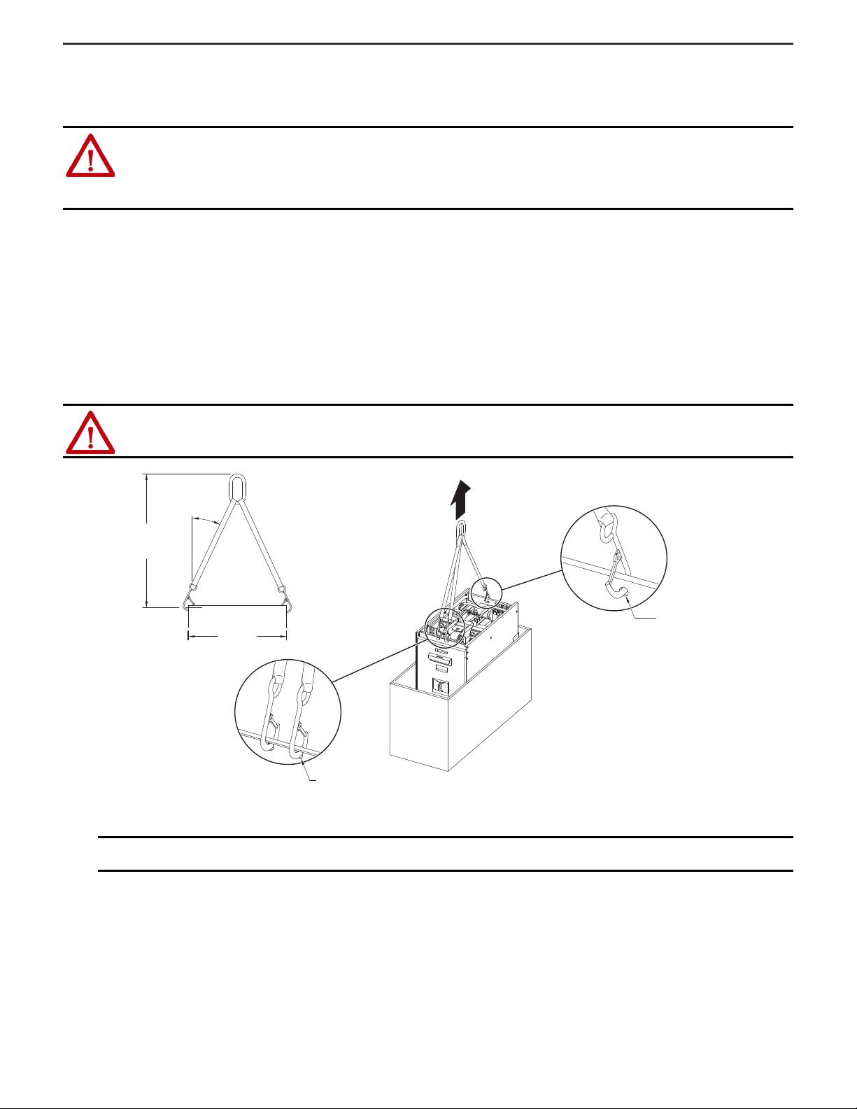
<45°
397
(15.6)
>199
(7.8)
Ø7
(0.3)
Ø10
(0.4)
Dimensions are in millimeters and (inches).
Read the Lifting Precautions
Read these precautions before attempting to lift a DC precharge module.
ATTENTION: All equipment and hardware that is used to lift the module must be properly sized and rated to lift and hold the weight of the module
safely. To guard against possible personal injury or equipment damage:
• Inspect all hardware for proper attachment before a module is lifted.
• Do not allow any part of the module or lift equipment to contact electrically charged conductors or components.
• Do not subject the module to high rates of acceleration or deceleration during a lift or transportation.
• Do not allow personnel or their limbs directly beneath the module during a lift.
Module Weight
All lifting equipment must support the approximate maximum DC precharge module weight of 41 kg (88 lb).
Lift the Module
Follow theses steps to lift the module.
1. Insert and secure the appropriate hardware in the designated lift holes (as shown in the illustration).
ATTENTION: To guard against equipment damage, verify that the hardware is securely connected to the correct lifting holes in the module as shown.
2. Slowly lift the module from the shipping container and transport the module to the installation location.
IMPORTANT
Interconnection wires protrude from the bottom of the module. Be sure that the module does not crush the wires when placed on a flat
surface or is installed.
2 Rockwell Automation Publication 750-IN103B-EN-P - June 2020

PowerFlex 755TM DC Precharge Modules Unpacking and Lifting Instructions Installation Instructions
Additional Resources
These documents contain additional information concerning related products from Rockwell Automation.
Resource Description
Provides detailed information on:
PowerFlex 755TM IP00 Open Type Kits Technical Data, publication 750-TD101
PowerFlex 755TM IP00 Open Type Kits Installation Instructions, publication 750-IN101 Provides instructions to install IP00 Open Type kits in user-supplied enclosures.
PowerFlex 750-Series Service Cart Instructions, publication 750-IN105
PowerFlex 750-Series Products with TotalFORCE Control Hardware Service Manual,
publication 750-TG100
Industrial Automation Wiring and Grounding Guidelines, publication 1770-4.1
Product Certifications website, rok.auto/certifications Provides declarations of conformity, certificates, and other certification details.
•Kit selection
• Kit ratings and specifications
• Option specifications
Provides detailed set-up and operating instructions for the module service cart
and lift extension option.
Provides detailed information on:
• Preventive maintenance
• Component testing
• Hardware replacement procedures
Provides general guidelines for installing a Rockwell Automation industrial
system.
You can view or download publications at rok.auto/literature
.
Rockwell Automation Publication 750-IN103B-EN-P - June 2020 3

Rockwell Automation Support
Use these resources to access support information.
Technical Support Center Find help with how-to videos, FAQs, chat, user forums, and product notification updates. rok.auto/support
Knowledgebase Access Knowledgebase articles. rok.auto/knowledgebase
Local Technical Support Phone Numbers Locate the telephone number for your country. rok.auto/phonesupport
Literature Library Find installation instructions, manuals, brochures, and technical data publications. rok.auto/literature
Product Compatibility and Download Center
(PCDC)
Download firmware, associated files (such as AOP, EDS, and DTM), and access product
release notes.
rok.auto/pcdc
Documentation Feedback
Your comments help us serve your documentation needs better. If you have any suggestions on how to improve our content, complete the form at rok.auto/docfeedback.
Waste Electrical and Electronic Equipment (WEEE)
At the end of life, this equipment should be collected separately from any unsorted municipal waste.
Rockwell Automation maintains current product environmental compliance information on its website at rok.auto/pec.
Your comments help us serve your documentation needs better. If you have any suggestions on how to improve our content, complete the form at rok.auto/docfeedback.
For technical support, visit rok.auto/support
Rockwell Otomasyon Ticaret A.Ş. Kar Plaza İş Merkezi E Blok Kat:6 34752 İçerenköy, İstanbul, Tel: +90 (216) 5698400 EEE Yönetmeliğine Uygundur
Allen-Bradley, expanding human possibility, PowerFlex, and Rockwell Automation are trademarks of Rockwell Automation, Inc.
Trademarks not belonging to Rockwell Automation are property of their respective companies.
Publication 750-IN103B-EN-P - June 2020 | Supersedes Publication 750-IN103A-EN-P-April 2016
Copyright © 2020 Rockwell Automation, Inc. All rights reserved. Printed in the U.S.A.
.
*PN-591654*
PN-591654
 Loading...