

Page 1
6182 Windows CE
User
Industrial Computer
Manual
Page 2
Important User Informa tion Solid state equipment has operational characteristics differing from those of
electromechanical equipment. "Safety Guidelines for the Application, Installation, and
Maintenance of Solid State Controls" (Publication SGI-1.1) describes some important
differences between solid state equipment and hard-wired electromechanical devices.
Because of this difference, and because of the wide variety of uses for solid state
equipment, all persons responsible for applying this equipment must satisfy themselves
that each intended application of this equipment is acceptable.
In no event will Rockwell Automation be responsible or liable for indirect or
consequential damages resulting from the use or application of this equipment.
The examples and diagrams in this manual are included solely for illustrative purposes.
Because of the many variables and requirements associated with any particular
installation, Rockwell Automation cannot assume responsibility or liability for actual use
based on the examples and diagrams .
No patent liability is assumed by Rockwell Automation with respect to use of the
information, ci rcui ts , equi pment , or software de scrib ed in this manual.
Reproduction of the contents of this manual, in whole or in part, without written
permission of Rock well Autom ation i s prohi bite d.
Throughout this manual, we use notes to make you aware of safety considerations.
ATTENTION:
circumstances that can lead to personal injury or death,
property damage, or economic loss.
Important:
and understanding of the product.
Identifies information that is especially important for successful application
Identifies information about practices or
Publication 6182-UM001B-EN-P
Page 3

Using this Manual Preface
V
V
Who Should Use This Manual................................................. P-1
Purpose of this Manual............................................................P-1
Contents of this Manual...........................................................P-2
Manual Conventions................................................................P-3
Allen-Bradley Support ............................................................P-3
Computer Features Chapter 1
Chapter Objectives..................................................................1-1
6182 Computer Versions..........................................................1-1
6182 Computer Pa cking List ...................................................1-1
6182 Hardware........................................................................1-2
6182 Software.........................................................................1-2
Features of the 6182 Computer................................................1-4
LED Indicators........................................................................1-8
7
7D
DEOH R
EOH RI
I &RQWH
&RQWHQ
QW
W
Install atio n Chapter 2
Chapter Objectives..................................................................2-1
European Union Compliance...................................................2-1
Environmental Considerations.................................................2-1
Mounting Hardware................................................................2-1
Tools Required........................................................................2-2
Mounting Clearances...............................................................2-2
Mounting Dimensions .............................................................2-3
Mounting Cutouts ................................................................... 2-5
Panel Mounting.......................................................................2-5
Power Connections.................................................................. 2-7
Relay Output...........................................................................2-8
Connecting External
Chapter 3
Devices
Chapter Objectives..................................................................3-1
Safety Precautions...................................................................3-1
Connecting USB Devices........................................................3-2
Connecting PS/2 Keyboard and Mouse....................................3-3
Connecting to an Ethernet Network.........................................3-4
Connecting Serial Devices.......................................................3-5
Connecting Parallel Devices....................................................3-6
Connecting an External Video Monitor....................................3-7
Connecting to Diagnostic Relay Output...................................3-8
Page 4

toc-ii
Table of Contents
Adding/Remov ing Int er nal
Components
Installing/Removing Front
Bezel Ass emb ly It e ms
Chapter 4
Chapter Objectives..................................................................4-1
Safety Precautions...................................................................4-1
Thermal Considerations for Add-In Cards................................4-2
Opening or Removing the Chassis...........................................4-2
Adding/Removing PC Cards (PCMCIA).................................4-4
Adding/Removing a PCI Card.................................................4-6
Adding/Removing RAM Memory...........................................4-8
Adding/Removing...................................................................4-9
Disk-On-Chip Memory............................................................4-9
Chapter 5
Chapter Objectives..................................................................5-1
Safety Precautions...................................................................5-1
Replacing the Front Bezel Assembly .......................................5-1
Replacing Bezel Cables...........................................................5-2
Disassembling the Front Bezel ................................................5-3
Replacing the Front Bezel Plastic Overlay...............................5-6
Replacing LCD Backlight Tubes .............................................5-7
Installing Keypad Legend Strips..............................................5-8
Installing/Removing
Chapter 6
Computer Cha s si s Items
Chapter Objectives..................................................................6-1
Safety Precautions...................................................................6-1
Replacing the Computer Chassis ............................................. 6-1
Replacing Computer Power Supply .........................................6-2
Initial Operation and Setup Chapter 7
Chapter Objectives..................................................................7-1
Operating Recommendations...................................................7-1
Ope rator A cce ss......................................................................7-1
System Checkout.....................................................................7-1
System Reset...........................................................................7-2
Publication 6182-UM001B-EN-P
Page 5

Table of Contents
toc-iii
Windows CE Operating
Chapter 8
System
Chapter Objectives..................................................................8-1
Windows CE Architecture .......................................................8-1
6182 Standard Windows CE Programs .................................... 8-2
Using Windows CE.................................................................8-3
Control Panel Applications......................................................8-6
6182 Memory Usage ...............................................................8-6
Keypad Operation Chapter 9
Chapter Objectives..................................................................9-1
Keypad Operation...................................................................9-1
Keypad Layout ........................................................................9-1
Setting Up the Keypad.............................................................9-6
Display S et ti n g s Chapter 10
Chapter Objectives................................................................10-1
Setting Up the Display...........................................................10-1
Touchscreen Calibrati on Chapter 11
Chapter Objectives................................................................11-1
Setti n g Touchscreen Properties..............................................11 - 1
Hardware Monitor Chapter 12
Chapter Objective.................................................................. 12-1
Hardware Monitor System Software......................................12-1
Using the Hardware Monitor .................................................12-2
Watchdog Timer Chapter 13
Chapter Objective.................................................................. 13-1
Watchdog Functionality.........................................................13-1
Using the Watchdog Timer System Software .........................13-2
Publication 6182-UM001B-EN-P
Page 6

toc-iv
Table of Contents
Communic ations
Chapter 14
Configuration
Chapter Objectives................................................................14-1
Setting Up Ethernet Communications....................................14-1
Setting Up Serial Communications........................................14-4
Managing User Applications Chapter 15
Chapter Objectives................................................................15-1
Installing and Using Microsoft ActiveSync............................15-1
Installing/Removing Applications on the 6182 Computer.......15-3
Transferring Files To and from the 6182 Computer................15-4
Upgrading the 6182 Windows CE Operating System.............15-4
System Troubleshootin g
Chapter 16
Chapter Objectives................................................................16-1
Hardware Diagnostics ...........................................................16-1
Troubleshooting Procedure....................................................16-1
Troubleshooting Check Lists................................................16-2
Resetting the Windows CE Registry......................................16-4
Maintenance Chapter 17
Chapter Objectives................................................................17-1
Cleaning the Display.............................................................17-1
Replacing the Battery............................................................17-2
Restoring the 6182 Computer................................................17-2
Replacement Parts.................................................................17-3
Specifications Appendix A
Proce ssor Board
Appendix B
Specific atio ns
Processor Board Specifications............................................... B-1
Boot Code Information........................................................... B-1
Publication 6182-UM001B-EN-P
Page 7

6182 Compatible Devices Appendix C
Parallel Port Printers...............................................................C-1
PC Cards................................................................................C-1
Table of Contents
toc-v
6182 Point-to-Point
Communications
Appendix D
COM2 RS232 Comm un i cations.............................................D- 1
Index
Publication 6182-UM001B-EN-P
Page 8

toc-vi
Table of Contents
Publication 6182-UM001B-EN-P
Page 9

Who Should Use This
Manual
Purpose of this Manual
33U
UH
HI
ID
DFH
FH
8VLQJ WKLV 0DQXDO
8VLQJ WKLV 0DQXDO
Read this preface to familiarize yourself with the rest of the manual. The
preface covers the following topics:
wh o shou ld use t his ma nual
•
the purpose of the manual
•
co ntent s of th e manual
•
conventions used in this manual
•
Allen-Bradley support
•
Use this manual if you are responsible for installing, using, or
troubleshooting the 6182 Windows CE Industrial Computer.
For users interested in writing their own application software for the
6182 Computer, you will need to order the
development kit. This catalog number includes a detailed technical
manual describing how to develop software applications for the 6182
Computer, along with a complete library of 6182 interfaces and
development tools on CDROM.
6189-SDK
software
This manual is a user guide for the 6182 Windows CE Industrial
Computer. It gives an overview of the system and describes procedures
you use to:
install the 6182 Computer in a panel or enclosure
•
install and remove system components
•
run the system
•
troub lesho ot the system
•
Page 10

P-2
Contents of this Manual
Chapter Title Contents
Preface Desc ribes the pur pose, background, an d scope of
this manual. Also specifies the intended audience.
1 Com puter Features Sho w s the d iff erent vers i ons and features of the
618 2 Computer .
2 Installati on Desc ribes ho w to install the 6 182 Com puter in a
pan el or encl osur e. Also how to connect power,
network, and relay output.
3 Connecting External Devices
4 Adding/Removing Internal
Components
5 Installing and Removing Front
Bezel Assembly Items
6 Installing and Removing
Com puter Cha ssis Items
7 Initial Operation and Setup Tells how to start and checkout the system.
8 Windows CE Operating System
9 Keypad Operation Explains how the 6182 keypad functions, and how
10 Display Settings Explai ns how to configure the 6182 display
11 Touchscreen Cali bration Explains how to calibrate the touchscreen on the
12 Hardware Monitor
13 Watchdog Timer
14 Commu nication s Configurati on Explains how to configure the 6182 to
15 Managing User Applications Explains how to install and configure user
16 System Troubleshooting
17 Maintenance Gives procedures for cleaning the 6182 Computer
Tells how to connect external devices to the
various 6182 ports.
Gives procedures for ad ding/removing RAM and
ROM memory , a d d- in PCI and PC cards.
Gives procedures for installing or removing front
bezel items, including display backlight tubes.
Gives procedures for removing or installing
computer chassis items.
Pro v ides an overview of th e 6182 Wi ndow s C E
operating system and its native applications and
utilities.
to use th e Keypa d conf iguration app lic at ion.
settings.
618 2 Computer .
Explains how to use the Hardware Monitor
application to perform hardware diagnostics.
Explains how to use the Watchdog Timer
application to reset the 6182 in case of lockup.
communicate with a host computer.
applications on the 6182 computer using Microsoft
ActiveSync. Also tells how to move data files to
and from the 6182 computer, and upgrade the
operating system.
Explains how to interpret and correct problems
with the 6182 Computer.
display.
Publication 6182-UM001B-EN-P
Page 11

Chapter Title Contents
Manual Conventions
Allen-Bradley Support
Appendi x A Spec ifi cations Pro vides physical, electri cal, envi r onmental, and
functional specifications.
Appendix B Processor Board Specifications Provides information on the 6182 Computer
processor board.
Appendix C 6182 Compatible Devices
Appendix D
6182 Point-to-Point
Communications
Lists the devices that are compatible with the
6182.
Describes how to connect the 6182 to various
devices.
The following conventions are used throughout this manual:
Bulleted lists such as this one provide infor mation, not procedural
•
steps.
Numbered lis ts pro vide s equ enti al steps or hierar chical inf o rmation.
•
Allen-Bradley offers support services worldwide, with over 75
Sales/Support Offices, 512 authorized Distributors and 260 authorized
Systems Integrators locat ed thr oughout the United States alone, plus
Allen-Bradley representatives in every major country in the world.
P-3
Local Product Support
Contact your local Allen-Bradley representative for:
sales and order support
•
product tech nical tra i ning
•
warranty support
•
support service agreements
•
Technical Product Assistance
If you need to contact Allen-Bradley for technical assistance, please
review the information in the System Troubleshooting chapter first.
Then call your local Allen-Bradley representative or contact AllenBradley technical support at (440) 646-5800.
For additional product information and a description of the technical
services available, visit the Rockwell Automation/Allen-Bradley Internet
site at http://www.ab.com.
Publication 6182-UM001B-EN-P
Page 12

P-4
Publication 6182-UM001B-EN-P
Page 13
&K
Chapter Objectives
6182 Computer Versions
6182 Computer Packing
&KD
DSWHU
SWHU
&RPSXW
&RPSXWH
This chapter provides an overview of the 6182 Windows CE Industrial
Computer including:
available versions
•
software
•
additional catalog items
•
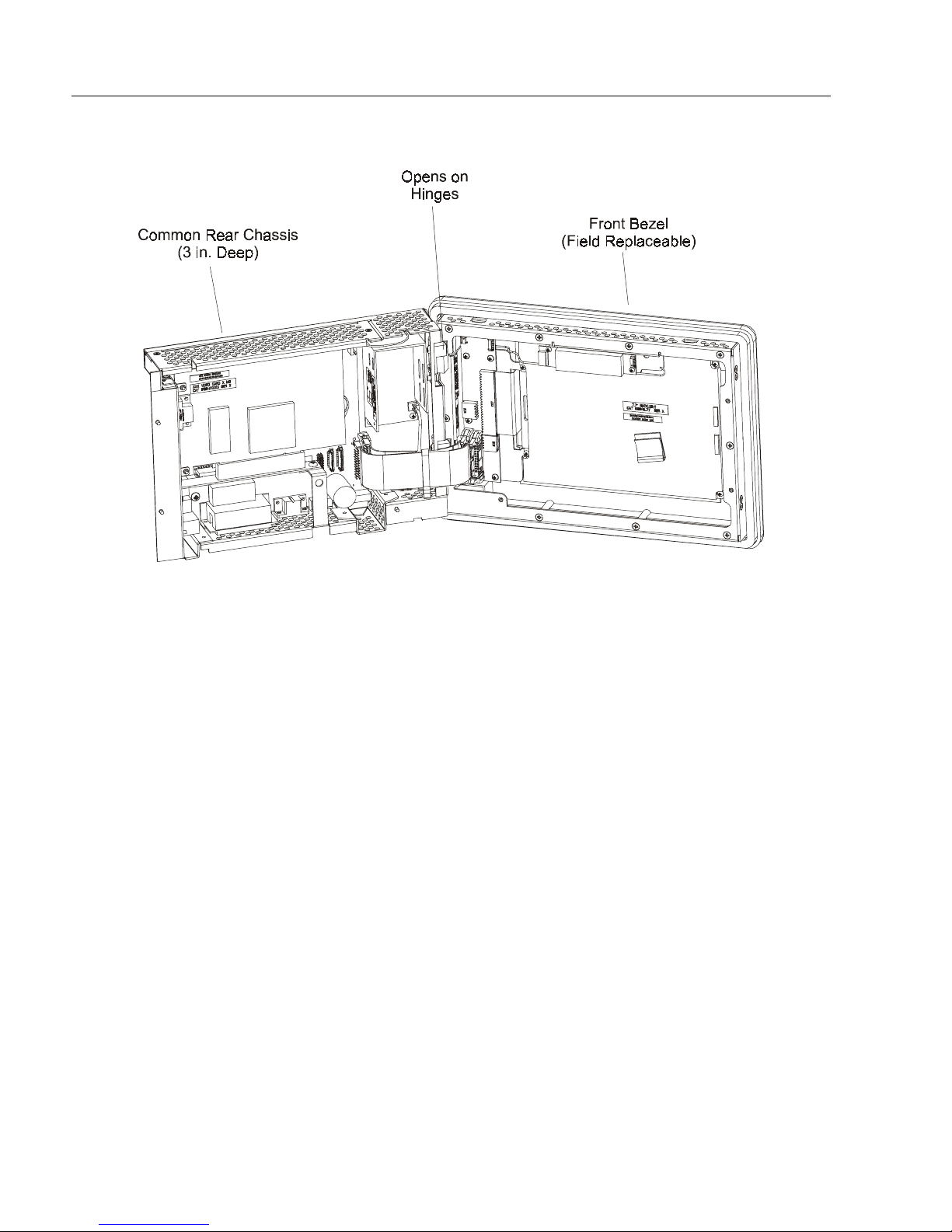
The 6182 computer is comprised of a front bezel assembly and computer
chassis. The computer chassis is common to all 6182 versions, and
contains the processor board, power supply, and add-in cards. It is
attached to the front bezel assembly with a hinge, so it can be easily
opened for int ernal access.
The 6182 front bezel assembly contains the LCD display, keypad, and
touchscreen features. A variety of front bezels are available for the 6182:
HU
U)
)H
HD
DW
WXU
XUHV
HV
List
7.7-in. STN display with keypad a nd optiona l touchscreen
•
(8K, 8KT)
12.1-in. TFT display with keypad and optional touchscreen
•
(12K, 12KT)
12.1-in. TFT display with touchscreen (12T)
•
Non-display "brick" (NDB) computer
•
The 6182 Computer is delivered with the following
items:
Computer with preinstalled Windows CE operating system
•
Mounting clips (4)
•
Power supply ter minal block
•
Ou tput r elay termina l block
•
6182 Applications and Accessories CD-ROM
•
6182 User Manual (this document, Publication 6182-UM001B-EN-P)
•
Installation Guide (Publication 6182-IN001A-EN-P)
•
Page 14

1–2
6182 Hardware
6182 Software
Computer Feat ur es
Microsoft Windows CE License Agr eement (Part 998084-010)
•
Software manuals and media for optional bundled softwar e
•
applications.
The 6182 Computer contains several hardware features designed to make
it a f lexible compu ter p latform for running indu stri al ap p lic ati ons.
MIPS 225MHz 32-bit RISC Processor, with hardware floating point
•
coprocessor.
32MB-256MB Disk-On-Chip flash ROM, field upgradeable
•
32MB-256MB Dyna mic RAM, field upgradeable
•
128KB battery-backed static RAM, for high speed persistent data
•
storage
Battery-backed real time clock/calendar
•
Hardware voltage/temperature monitoring
•
Software-based watchdog timer
•
Diagnostic Relay Output.
•
The 6182 Computer is shipped with a product-specific version of the
Microsoft Window CE operating system already installed in the product.
This is a full installation of Windows CE, complete with the graphical
Desktop, file management features, and Internet Explorer application.
Additional user application software may also be pre-installed,
depending on the 6182 version or dered.
The Windows CE operating system is stored in a secured flash ROM
location, and cannot be corrupted by any normal user or software
applications. Therefore, no Windows CE media is shipped with the 6182
product. The 6182 operating system can be field upgraded to new
versions. For instructions, refer to Chapter 15, Managing User
Applications.
New user applications can be field-installed on the 6182 Computer.
Chapter 15, Managing User Applications, describes the various methods
for installing sof twa re ap plications. The software vendor should also
provide instructions for loading the application program.
Publication 6182-UM001B-EN-P
Page 15

Computer Feat ur es
1–3
6182 Applications and Accessories CDROM
This CDROM delivered with the 6182 Computer contains the Microsoft
ActiveSync application software, the 6182 User Manual in Adobe
Acrobat PDF format, the 6182-specific backup files, and some Windows
CE application too ls.
Microsoft ActiveSync
The 6182 Computer supports the Microsoft ActiveSync communication
utility. Chapter 15, Managing User Applications, describes how to
install and use ActiveSync on a desktop PC. The ActiveSync program is
used to manage user applications and data files on the 6182 Windows CE
Computer. The connection between 6182 and PC can be either an
RS232 null modem cable (6189-2NMCBL) or through the Ethernet port.
Note:
To install Microsoft ActiveSync on a desktop PC for the
first time, you must use a null modem serial cable.
An ATA me mory card can also be us ed to transfer files betw een a PC and
the 6182 Computer. Chapter 4, Adding/Removing Internal Components,
describes how to install and remove PC cards on the 6182.
6182 User Manual
An electronic copy of this manual (publication 6182-UM001B-EN-P) is
distributed on the 6182 Applications and Accessories CDROM. The user
manual file is in a PDF format. A copy of the Acrobat reader software
program is also shippe d on th is CDROM.
6182 Backup Files
The 6182-specific operating system, program, and application files are
shipped on the C D ROM. Chapter 15, Managing User Applicati ons,
describes the 6182-specific files stored on the Disk-On-Chip flash
memory.
Windows CE Applications
Some useful Windows CE utility programs are included on the 6182
Applications and Accessories CDROM. These utilities include network
tools to verify Ethernet connections, a registry edit tool, and a scribble
application to test the touchscreen. See each application’s online help for
details on the program’s features.
Publication 6182-UM001B-EN-P
Page 16
1–4
Features of the 6182
Computer
Computer Feat ur es
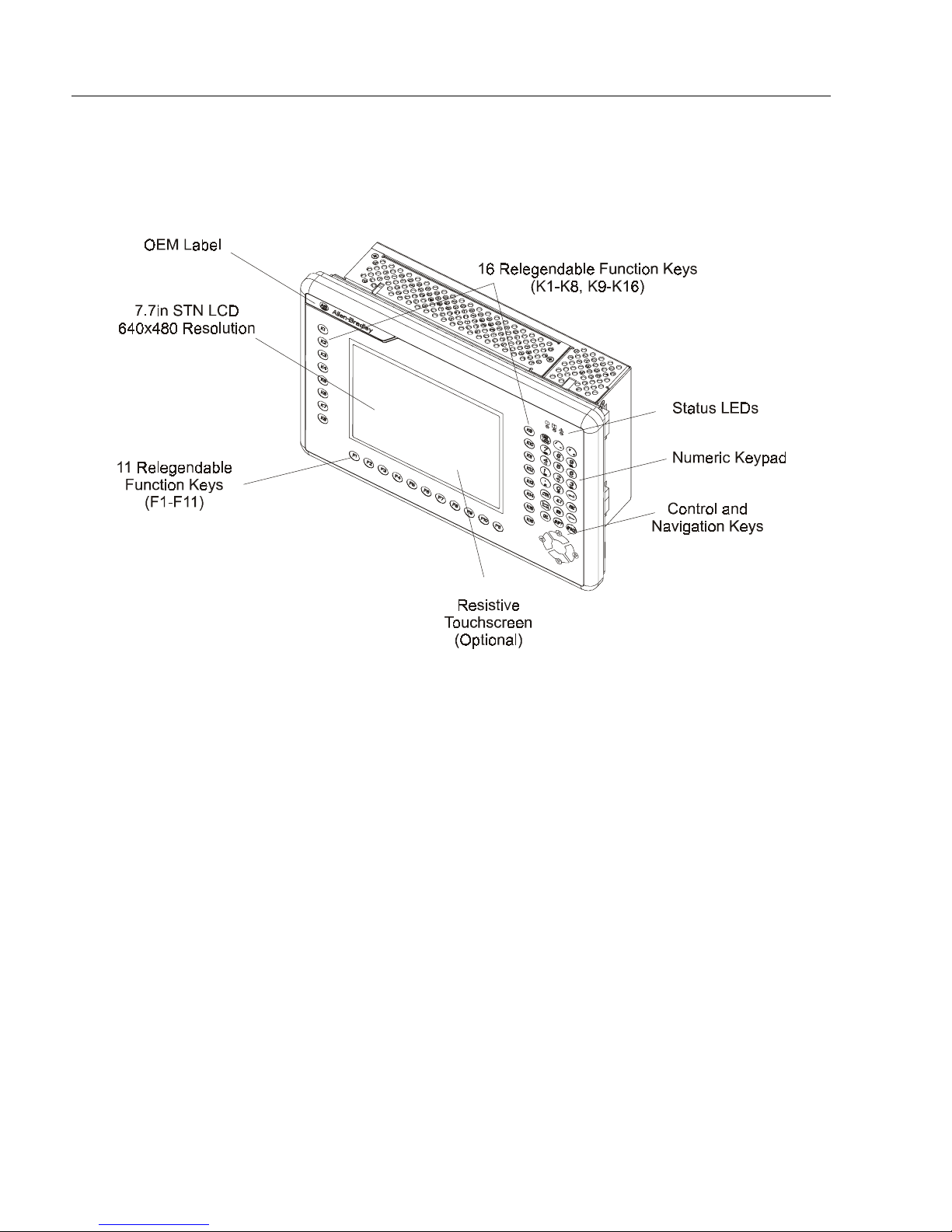
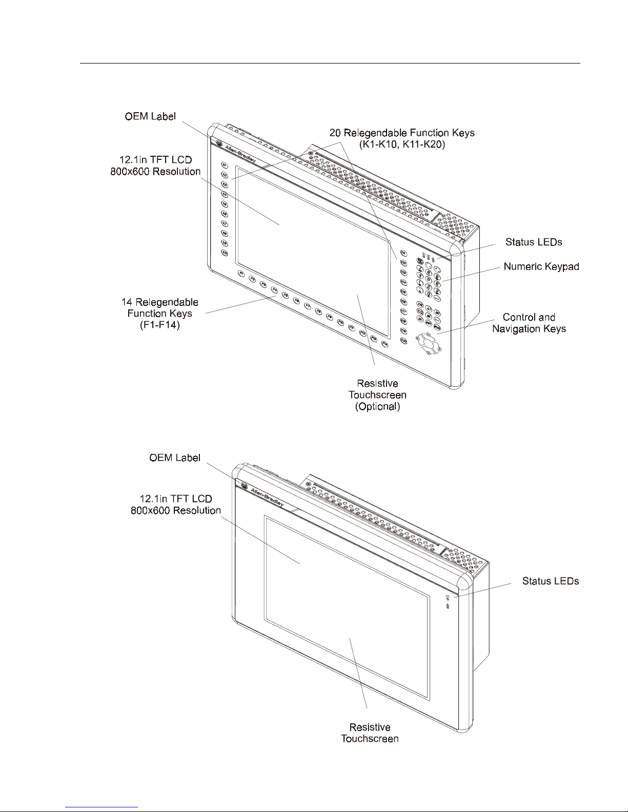
The following illustrations show the major features and controls of the
display versions of the 6182 Computer.
6182 Computer – 7.7 in. Version with Keypad
Publication 6182-UM001B-EN-P
Page 17
Computer Feat ur es
6182 Computer – 12.1 in. Version with Keypad
1–5
6182 Computer – 12.1 in. Version with Touchscreen
Publication 6182-UM001B-EN-P
Page 18
1–6
Computer Feat ur es
6182 Computer Common Chassis
Publication 6182-UM001B-EN-P
Page 19
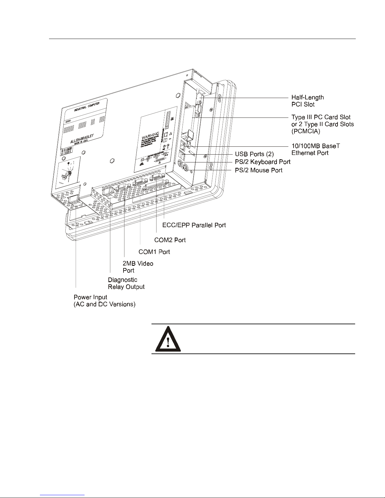
6182 Computer Connectors
Computer Feat ur es
1–7
WARNING:
EXPLOSION HAZARD! Substitution of
comp onents may i mp air suitabilit y f or Class I, D iv 2
hazardou s locati ons.
Publication 6182-UM001B-EN-P
Page 20
1–8
LED Indicators
Computer Feat ur es
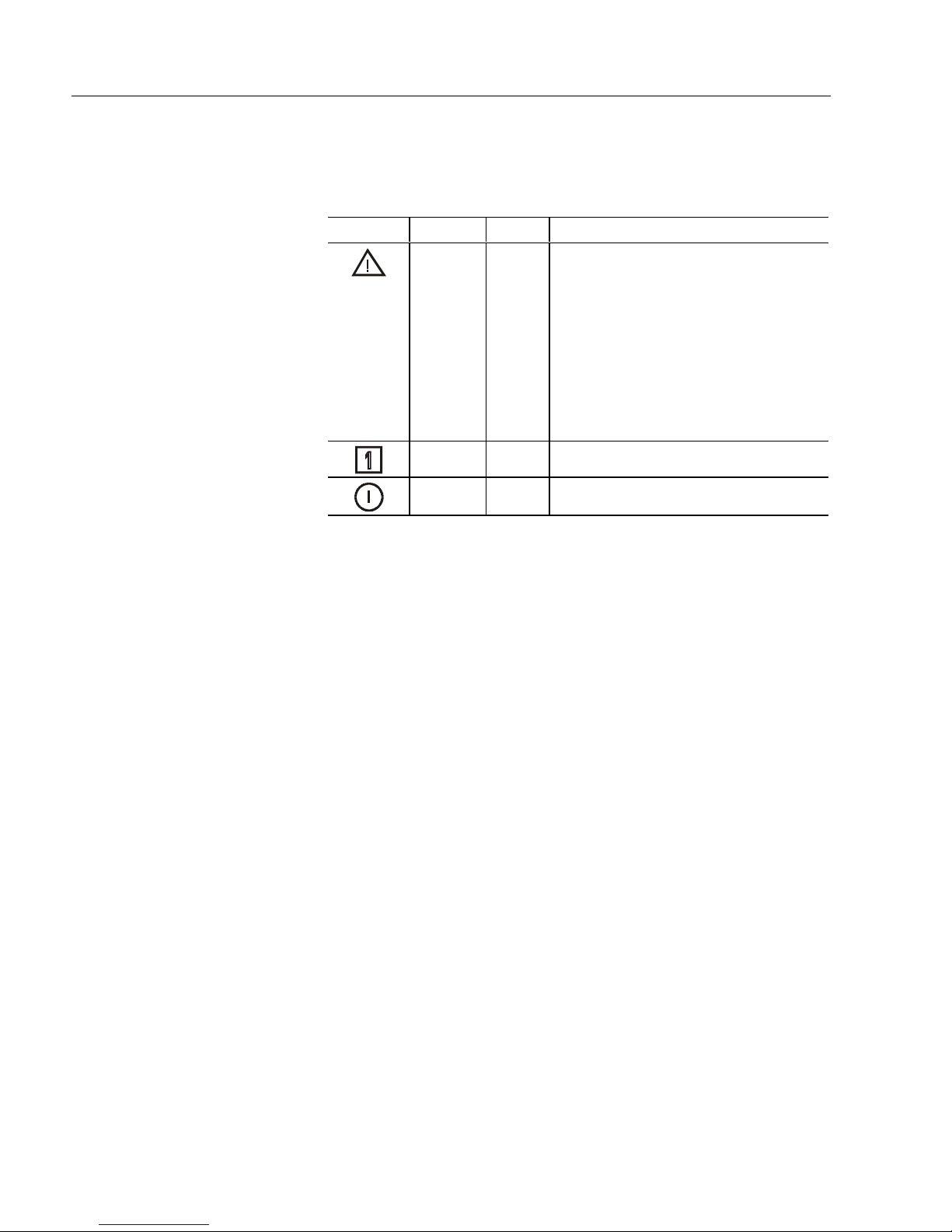
The following table shows the LED indicators on the 6182 Computer.
Table A
LED Indicators (Display Versions Only)
Indicator Position Color Indicates
Right Red Diagnostics. Indicates that one of the
following conditions exists when lit:
•
Overtemperature. Tem pera ture i nsid e
the 6182 C omputer enclo sure is
above defined threshold.
•
Vol tage. Voltages not within
specification.
Refer to Chapter 16, System
Troubleshooting, for inf ormation on
reso lving diagnos tic conditions.
Cent er Gr een Numlock key act ivated when lit
Left Green Power On when lit
Note:
The LEDs toggle on and off during power up.
Publication 6182-UM001B-EN-P
Page 21
Chapter Objectives
European Union
Compliance
Environmental
Mounting Hardware
Considerations
&K
&KD
DSWHU
SWHU
,QVWDOO
,QVWDOOD
This chapter describes installation of the 6182 Windows CE Industrial
Computer, including how to install the 6182 Computer in a panel using
mounting clips.
The 6182 Computer meets the European Union Directive requirements
when install e d within the Europea n Unio n or EE A regions and ha s the
CE mark. A copy of the Declaration of Conformity is available at the
Rockwell Automation/Allen-Bradley Internet site: www.ab.com
Mount the 6182 Computer in a panel or enclosure to protect the internal
circuitry. Versions with a gasketed bezel meet NEMA Type 1, 12, 13 and
4X (Indoor use) and IEC IP54, IP65 only when properly mounted in a
panel or enclosure having an equivalent rating. The non-display version
does not have a gasket and has a NEMA Type 1 and IEC IP2X rating.
Allow enough room within the enclosure for adequate ventilation. Also
consider heat produced by other devices in the enclosure. The ambient
temperature around the 6182 Computer must be maintained between 0
and 50 oC (32 o to 122 o F). The 6182 Computer is intended for use in
Pollution Degree 2 environments.
DWLRQ
WLRQ
o
Make sure you provide provisions for accessing the top, bottom, and side
panels of the 6182 Computer to install/remove components and to access
the connectors.
Versions of the 6182 Computer with a display are shipped with the
following mounting hardware:
Table B
Mounting Hardware
Item Description Quantity Use For
Mounting
Clips
4 Clips Panel or enclosure
mounting
Page 22
2–2
Tools Required
Mounting Clearance s
Installation
The following replacement clips can be ordered from Rockwell
Automation:
Part Number Descri ption Quantity Use For
6189-2MTGKIT8 Mounting clips
Package of 4
clips
Replacement item
In addition to the tools required to make the cutout, you will need a
#2 Phillips-head screwdriver and a torque wrench.
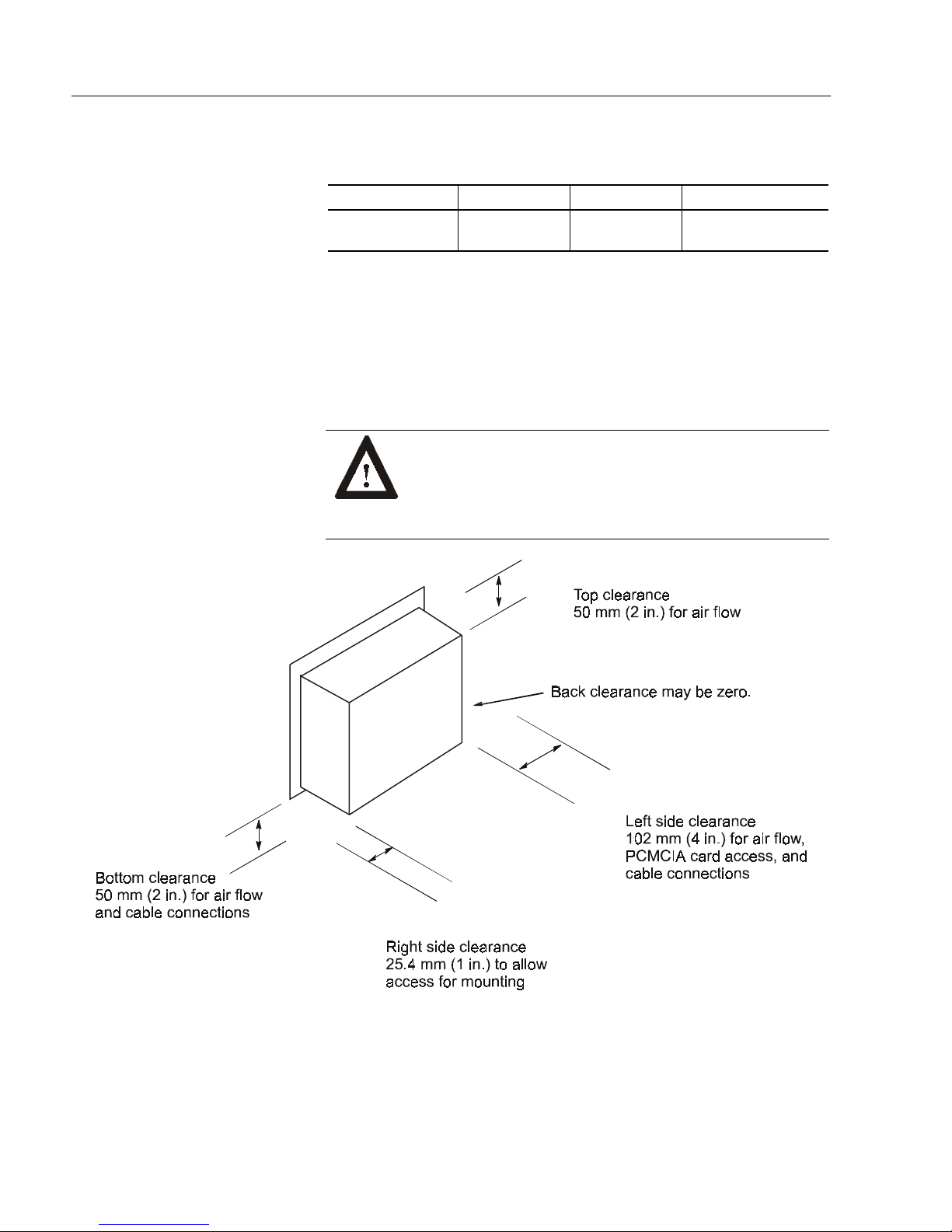
Allow adequate space for mounting, air flow, and maintenance. The
figure below shows recommended minimum clearances to other
components with i n th e rack or enclosure.
AT TENTION: The 6182 Computer should not be
operated within a confined space of the dimensions
shown below unless adequate ventilation or other cooling
methods are used to lower the air temperature within the
enclosure.
Publication 6182-UM001B-EN-P
Page 23
Installation
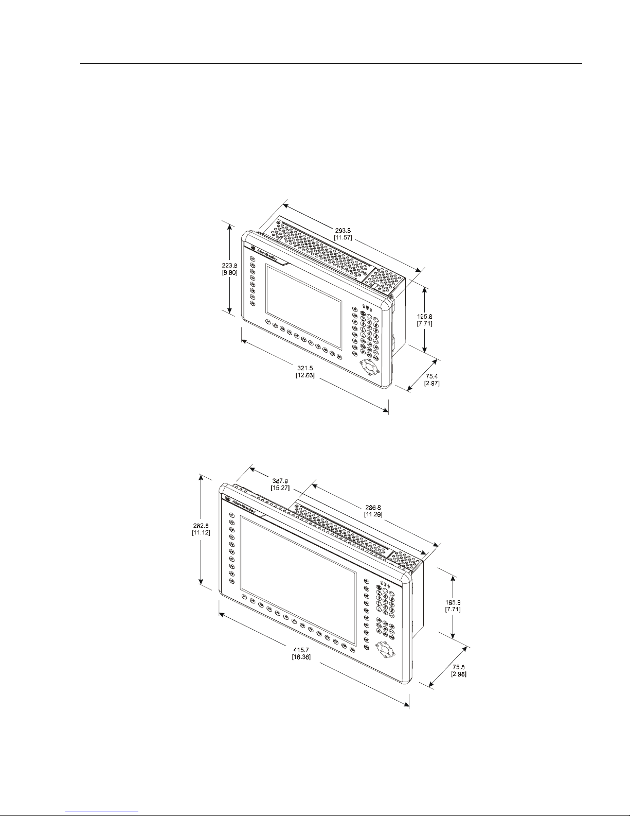
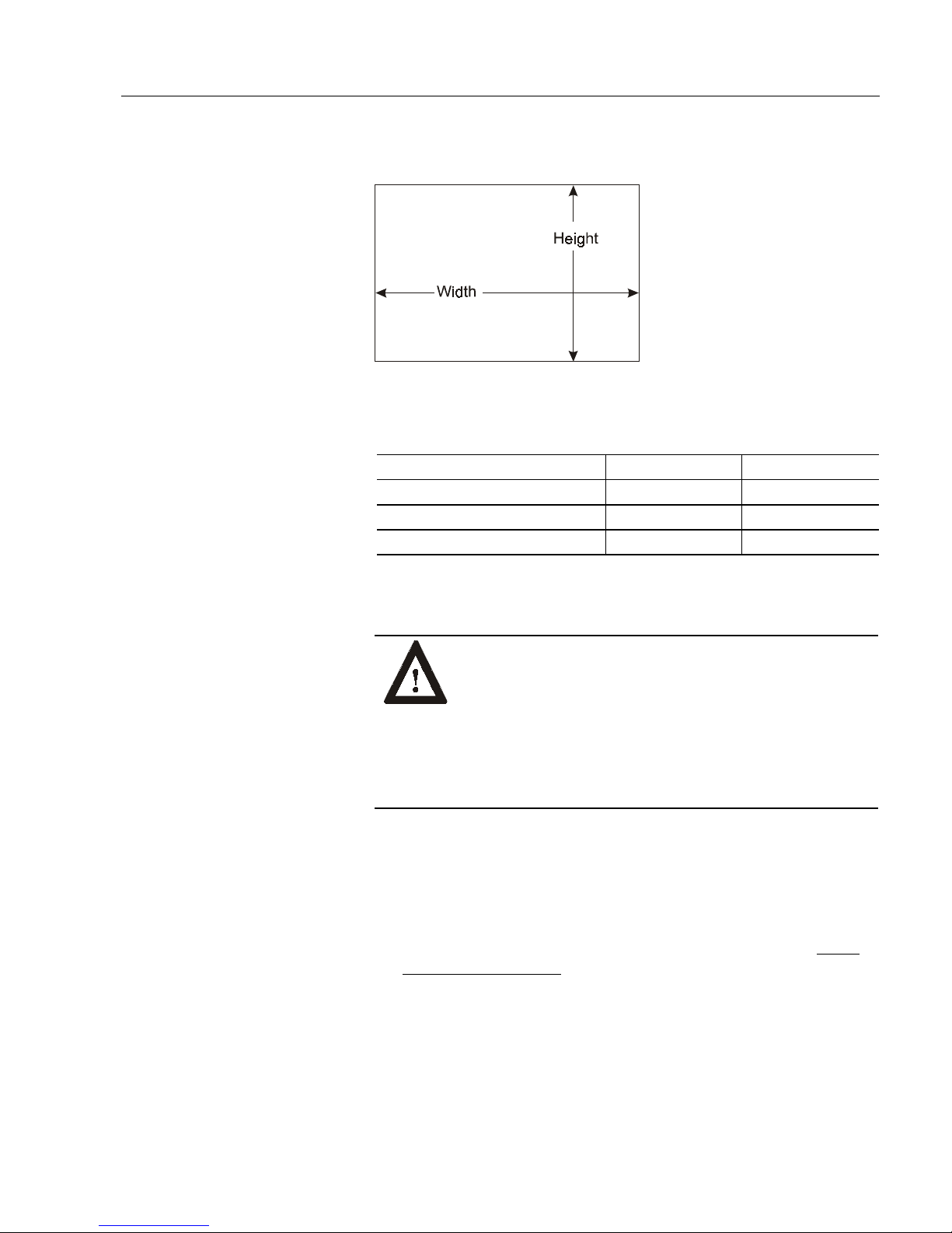
Mounting Dimens ion s
The following figures show the mounting dimensions for the 6182
Computer.
2–3
Note:
Measu rem ents in these figures are expresse d in m illime ters
[inches].
7.7 in. Version with Keypad
12.1 in. Version with Keypad
Publication 6182-UM001B-EN-P
Page 24
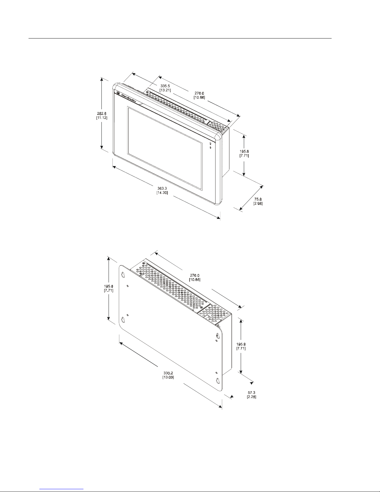
2–4
Installation
12.1 in. Version with Touchscreen
Non-Display Version
Publication 6182-UM001B-EN-P
Page 25
Installation
Mounting Cutouts
Panel Mounting
The following figure provides the dimensions for making the panel or
enclosure cutout for the 6182 Computer.
Table C
Mounting Cutout Sizes
Display Size Height Width
7.7 in. version with keypad 197.8 [7.79] 295.8 [11.65]
12.1 in. version with touchscreen 256.8 [10.11] 337.6 [13.29]
12.1 in. version with keypad 256.8 [10.11] 389.9 [15.35]
2–5
To install the 6182 Computer in a panel:
ATTENTION:
Disconnect al l el ect ri cal p ower from t h e
panel before making cutout.
Make sure the area around the panel cutout is clear.
Take precautions so that metal cuttings do not enter any
components that are already installed in the panel.
Failure to follow these warnings may result in personal
injury or damage to the panel components.
To install the 6182 Computer in a panel:
1. Cut an opening in the panel using the panel cutout dimensions
provided on Page 2-5.
2. Make sure the 6182 Computer sealing gasket is properly positioned
on the terminal. This gasket forms a compression type seal, do not
use sealing compounds.
3. Place the 6182 Computer in the panel cutout.
Publication 6182-UM001B-EN-P
Page 26
2–6
Installation
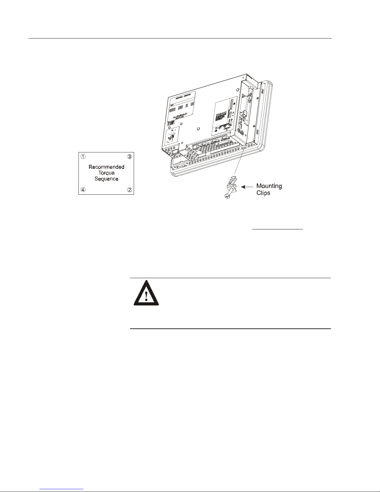
4. Install the mounting clips. The mounting clips slide into the slots on
the top and bottom of the 6182 Computer.
5. Gradually tighten the clips one at a time around the bezel using the
specified sequence. Repeat this process at least three times until the
clips are hand-tight and t he gasket is compressed uniformly a gains t
the panel.
6. Tighten mounting clips to a torque of 10 in–lbs (1.1 N•m) in the
sequence shown above. Do not over– tighten.
ATTENTIO N:
in–lbs
10
damage to the
Tighten mounting clips to a torque of
(1.1 N•m) to provide a proper seal and prevent
6182 Computer
. Allen–Bradley assumes
no responsibility for water or chemical damage to the
terminal o r oth er eq uipment withi n th e enclo s ure b ecau s e
of improper installation.
Publication 6182-UM001B-EN-P
Page 27
Installation
Power Connections
2–7
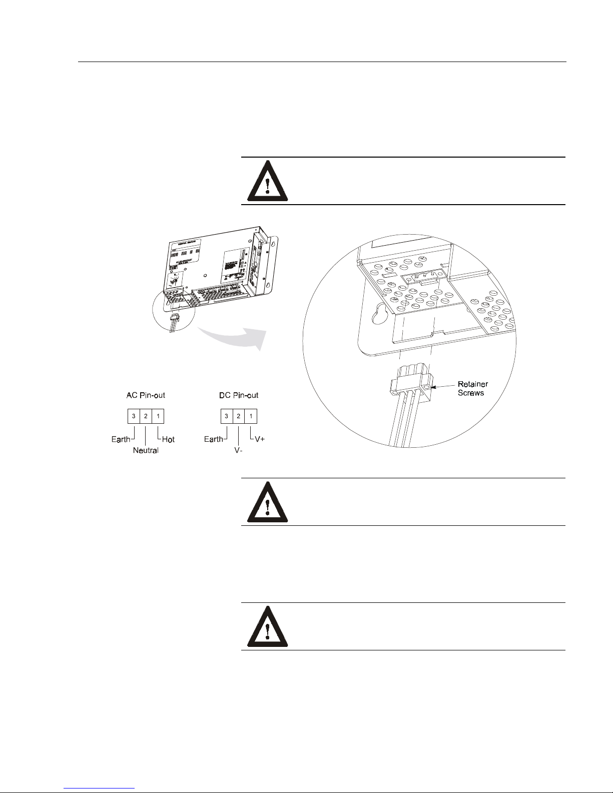
A three-contact removable terminal block is used to connect power to the
6182 Computer. The 6182 Computer AC version accepts 120/240V AC.
The AC power supply is autoranging. The DC version accepts 18-32V
DC . The removable ter m inal block s are di fferent on the AC and DC
versions and cannot be interchanged.
ATTENTION:
The power supply must be connected to
an earth ground. Failure to follow this warning could
result in s ever e el ect rical shock.
ATTENTIO N:
Some 1784 communication cards have a
connector like the one used for the 6182 power connector.
Do not plug power into connectors on these car ds .
The terminal block is equipped with two retainer screws to prevent
accidental interruption of power to the 6182 Computer. Tighten the
screws on the AC version to a torque of 5 in–lbs (0.56 N•m). Tighten the
screws on the DC version to a torque of 2.5 in–lbs (0.28 N•m).
WARNING:
EXPLOSION HAZARD! Do not co nnect
or disconnect equipment unless power has been swit ched
off or the area is known to be non-hazardous.
Publication 6182-UM001B-EN-P
Page 28
2–8
Relay Output
Installation
The following power supply terminal blocks can be ordered from
Rockwell A utom ation:
Part Number Description
6189-2ACCONN 120/240VAC Unit terminal block (qty 1)
6189-2DCCONN 24VDC Unit terminal block (qty 1)
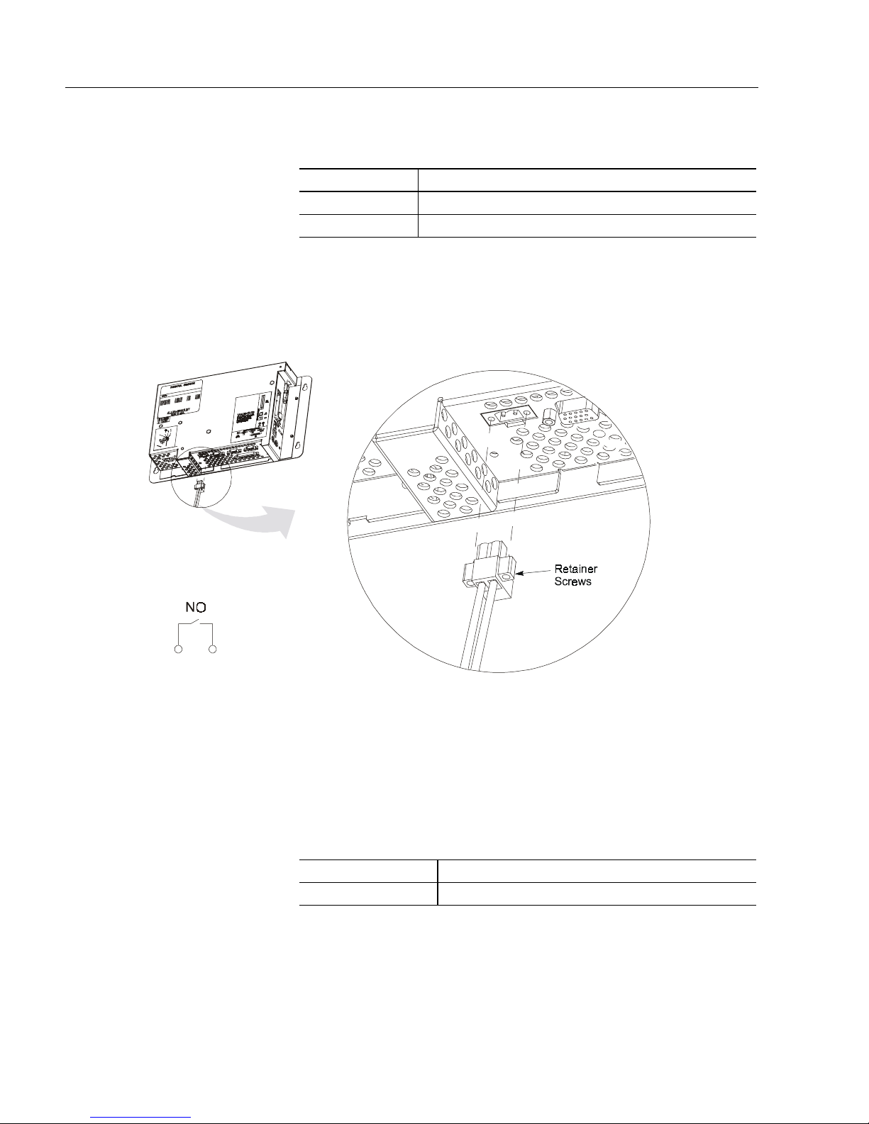
The 6182 Computer has a relay output. This output is a norm ally- open
hard contact relay rated for 24VDC, 500mA. A two-contact removable
terminal block is used to connect to the relay output.
Publication 6182-UM001B-EN-P
The terminal block is equipped with two retainer screws to prevent
accidental disconnection. Tighten these screws to a torque of 5 in–lbs
(0.56 N•m).
The f ollow ing r eplacement rela y outp ut termina l blocks can be ord ered
from Rockwell Automation:
Part Number Description
6189-2OUTCONN Relay output terminal block (qty 1)
Page 29
&K
Chapter Objectives
Safety Preca utions
&KD
DSWHU
SWHU
&RQQHFWLQ
&RQQHFWLQJ
This chapter describes how to connect a variety of external devices to the
6182 Computer. This chapter’s topics include:
USB devices
•
PS/2 keyboard and mouse
•
Ethernet network connection (RJ45)
•
Serial devices
•
Parallel devices
•
External video monitors
•
Diagnostic relay output
•
Make sure you disconnect all power to the 6182 Computer before
perfor mi ng any of the opera tions describe d in this chapter.
J ([W
([WH
HU
UQDO '
QDO 'H
HYLFHV
YLFHV
ATTENTIO N:
Computer and external devices before making any
connections. Failure to disconnect power could result in
damage to the 6182 Computer and/or external device.
As with all electronic devices, internal 6182 Computer components may
be damage d by Electr ostatic Di scharge (E SD). Do not touch con nector
pins when attaching external cables. Touch the metal chassis to
discharge yourself before connecting external cables.
Disconnect all power from the 6182
Page 30
3–2
Connecting USB Devices
Connecting External Devices
The 6182 Computer has two USB ports. The Windows CE operating
system currently only supports standard USB keyboard and mouse
devices with its native device drivers. A vendor-specific Windows CE
driver will be required for all other USB devices.
The USB device can plug into either of the two side panel USB ports as
shown below. While the USB interface is designed to be connected and
disconnected under power, the Windows CE operating system will not
automatically recognize any changes made under power.
Publication 6182-UM001B-EN-P
Table D
USB Stacked Connector Pin-Out
PIN Signal
1 USB0 VCC ( Swit ched FET curr ent protected)
2 USB0D3 USB0D+
4 USB0GND
5 USB1 VCC ( Swit ched FET curr ent protected)
6 USB1D7 USB1D+
8 USB1GND
9 SHLDGND
10 SHLDGND
Page 31

Connecting PS/2
Keyboard and Mouse
Connecting External Devices
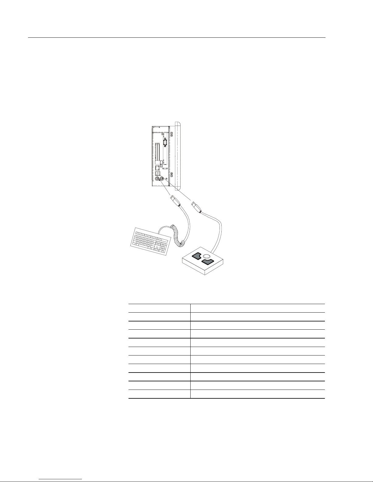
The mouse and keyboard plug into the side panel mouse and keyboard
ports as shown below. Any standard P S/2 keyboard and mouse devices
can be used. Both devices must be connected befor e power-up to be
recognized by the Windows CE operating system.
3–3
Table E
PS/2 Port Connector Pin-Out
PIN Signal
1 KBDATA
2 Not connected
3GND
4VCC
5 KBCLK
6 Not connected
7 MSDATA
8 Not connected
9GND
10 VCC
11 MSCLK
12 Not connected
13 Sh ield Grou nd
14 Sh ield Grou nd
15 Sh ield Grou nd
16 Sh ield Grou nd
17 Sh ield Grou nd
Publication 6182-UM001B-EN-P
Page 32

3–4
Connecting to an Ethernet
Network
Connecting External Devices
The 6182 Computer accommodates CAT5 twisted pair Ethernet cabling
with RJ45 connectors to support 10 Mbps and 100 Mbps network data
transfer rates. Shielded cabling is required to maintain EMI compliance.
Note:
For information on connecting the 6182 Computer to a host
PC using the Ethernet connection, refer to Chapter 14,
Communications Configuration.
Important:
Performance degradation of your Ethernet communications
is lik e ly to result if the un it or cables a re sub jected to
extreme radiated or conducted high-frequency noise. It is
the user’s responsibility to properly route cables and
condition input power in order to improve communication
reliability.
Proper cable routing and power conditioning is required to
ensure reliable Ethernet communications in industrial
environments. Rockwell Automation recommends that all
Ethernet cabling be routed through dedicated metal
conduits. Installing ferrite bead filters at cable ends may
also improve reliability.
Table F
RJ45 Ethernet Connector Pin-Out
PIN Signal
1LANTX+
2LANTX3 LANRX+
4LANGND
5LANGND
6 LANRX7LANTXDBN
8 LANRXDAN
9 LANSHLD1
10 LANSHLD2
Publication 6182-UM001B-EN-P
Page 33

Connecting Serial
Device s
Connecting External Devices
3–5
The 6182 Computer has two serial ports – COM1 and COM2, both with
DB9 male connectors.
The COM1 port supports RS232, RS422, and RS485 physical signals.
The COM1 p h y sic al sig n als are sof tware-s e lectable.
The COM2 port supports only RS232 physical signals. The COM2 port
is used to connect to a host PC using ActiveSync.
Note:
You must use a null modem cable (6189-2NMCBL) to
connect the COM2 port to a host PC. For information on
the null modem cable, refer to Appendix D, 6182 Point-toPoint Communications.
Note:
For information on connecting the 6182 Computer to a host
PC using the serial port, refer to Chapter 14,
Communications Configuration.
Table G
DB9 Male Connector Pin-Out
PIN
1
2
3
4
5
6
7
8
9
RS232 Signal
(COM1 and COM2)
DCD TXD(+)
RXD TXD(-)
TXD RXD(+)
DTR RXD(-)
SGND SGND
DSR DH485 TXENBL
RTS Not connected
CTS Not connected
RI Not connected
RS422/RS485 Signal
(COM1 Only)
Publication 6182-UM001B-EN-P
Page 34

3–6
Connecting Parallel
Devices
Connecting External Devices
The 6182 Computer has an ECP/EPP compatible parallel printer port
with a DB25 female connector. This port can be connected to any
standard parallel printer. However, the 6182 Windows CE operating
system only contains a Hewlett-Packard compatible printer driver. If
other printers are to be used, you must provide the associated Windows
CE printer driver if available.
Table H
Parallel Port DB25 Female Connector Pin-Out
PIN Signal
1 STROBE#
2PD0
3PD1
4PD2
5PD3
6PD4
7PD5
8PD6
9PD7
10 ACK#
11 BUSY
12 ERROR
13 SELECT
14 AUTOFD#
15 FAULT#
16 INIT#
17 SLCT IN#
18 GROUND
19 GROUND
20 GROUND
21 GROUND
22 GROUND
23 GROUND
24 GROUND
25 GROUND
Publication 6182-UM001B-EN-P
Page 35

Connecting an External
Video Monitor
Connecting External Devices
3–7
The 6182 Computer has an external HD15 video connector. It can drive
any external monitor that accepts VGA analog video signals.
Note:
For information on setting the video resolution and refresh
rate for an external monitor, refer to Chapter 10, Display
Settings.
Table I
HD15 Vi deo Connector Pin-Out
PIN Signal
1RED
2 GREEN
3BLUE
4 Not connected
5GND
6GND
7GND
8GND
9 Not connected
10 GND
11 Not connected
12 DDC_DATA (pull-up)
13 HSYNC
14 VSYNC
15 DDC_CLK (pull- up)
16 Shield ground
17 SLCT IN#
Publication 6182-UM001B-EN-P
Page 36

3–8
Connecting to Diagnostic
Relay Output
Connecting External Devices
The 6182 Computer has a relay output. This output is a norm ally- open
hard contact relay rated for 24VDC, 500mA. A two-contact removable
terminal block is used to connect to the relay output.
Note:
For instructions on connecting the relay output, refer to
Page 2-8.
The diagnostic rela y output can be used to drive a variety o f peripheral
signaling devices such as a tower annunciator light or an audible alarm
or buzzer. The output can also be connected to an embedded control
system to signal a 6182-generated event.
Publication 6182-UM001B-EN-P
Page 37

&K
Chapter Objectives
Safety Preca utions
&KD
DSWHU
SWHU
$
$G
GGLQJ
GLQJ5
&RPSRQHQWV
&RPSRQHQWV
This chapter describes how to open the chassis of the 6182 Computer
and r e move or install :
PC add-in cards (PCMCIA)
•
PCI add-in card
•
RAM
•
Disk-O n- Chip flash ROM
•
The 6182 Computer contains line voltages. Make sure you disconnect
all power to the 6182 Computer befor e removing covers or access
screws.
5HP
HPR
RYLQJ ,
YLQJ ,Q
QWH
WHU
UQDO
QDO
ATTENTION:
Computer before removing components. Failure to
disconnect power could result in severe electrical shock
or damage to the 6182 Computer.
Internal 6182 Computer components may be damaged by Electrostatic
Discharge (ES D). Make sure you wear a grounding strap whenever
handling circuit boards, memory modules or other internal components.
ATTENTION:
perform work in a static safe environment.
Electrostatic discharge can damage the 6182 Computer
and c omponents .
Disconnect all power from the 6182
Wear a wrist strap (well grounded) and
Page 38

4–2
Thermal Consider ations
Opening or Removing the
Adding/Removing Internal Components
for Add-In Cards
Chassis
The 6182 Computer accommodates one PCI compatible add-in card.
Due to thermal considerations with the unit, total add-in power is limited
to 7W of power dissipation (within the product enclosure).
Table J
PCI Card Current Limits
Voltage Current Limit at Specified Voltage
5V 1.0A
3.3V 0.1A
12V 0.1A
-12V -0.05A
This section shows how to open and close the 6182 chassis to access
internal components.
A TTENTION:
Review safety precautions on Page 4-1
before proceeding. Failure to follow proper safety
procedures could result in severe electrical shock or
damage to the 6182 Computer.
To open the chassis (display versions):
1. Disconnect power from the 6182 Computer.
2. Remove the 3 screws securing the chassis to the front bezel.
Publication 6182-UM001B-EN-P
3. Open the chassis away from the front bezel. Be careful not to stress
or disconnect the internal cables running between the chassis and
front bez e l.
Page 39

Adding/Removing Internal Components
To remove the chassis (display versions):
1. To remove the chassis completely from the front bezel, carefully
disconnect the internal cables from the chassis printed circuit board.
2. Remove the set-screw in the hinge, and lift the back chassis off the
front bez e l hinges.
4–3
To replace the chassis (display version):
1. To replace the chassis, remount the chassis onto the front bezel
hinges and reinstall the hinge set-screw. Reconnect the cables to the
chassis printed circuit board.
2. To close the chassis, slowly hinge the chassis back against the front
bezel. Be careful not to pinch the internal cables.
3. Reinstall the 3 screws to secure the chassis to the front bezel. Tighten
the screws to a torque of 6 - 8 in–lbs (0.7 - 0.9 N•m).
Publication 6182-UM001B-EN-P
Page 40

4–4
Adding/Removing PC
Adding/Removing Internal Components
To open the chassis (non-display versions):
1. Disconnect power from the 6182 Computer.
2. Remove the 4 nuts securing the chassis to the front plate.
3. To close the chassis, reinstall the 4 nuts to secure the chassis to the
front plate. Tighten the nuts to 6 - 8 in–lbs (0.7 - 0.9 N•m).
Cards (PCMCIA)
One Type III PC car d or two Type II PC cards (PCMCIA) may be
installed in the 6182 computer. While the 6182 PCMCIA slots are
electrically compatible with any standard PC card, special Windows CE
drivers are required to make the PC card function on the 6182 computer.
Refer to the application program to make sure it supports the desir ed PC
card.
The f ollow ing memory P C car ds can be ordered from Rockwe ll
Automation:
Part Number Description
6189-ATA32 32MB ATA flash memory PC card
A TTENTION:
Review safety precautions on Page 4-1
before proceeding.
Failure to follow proper s afety procedures c ould result in
severe electrical shock or damage to the 6182 Computer.
ATTENTION:
PC cards may be sensitive to ESD and
require careful handling. Hold cards only by the
edgesdo not touch connectors. After removing a card,
place the PC card in an anti-static wrapper.
Publication 6182-UM001B-EN-P
Page 41

Adding/Removing Internal Components
To install a PC card:
1. Locate the PC card slots on the side of the 6182.
2. Loosen the screw on the PC card retainer bracket covering the PC
card slot, if necessary.
3. Insert the PC card into the desired slot. Make sure the PC card is
fully seated and the slot ejector is out. Up to 2 Type II cards can be
installed in the 6182.
4–5
Note:
Most PC cards are hot-swappable on the 6182. You do
not need to turn off power to the unit. Install one PC
card at a time to ensure correct installation.
4. Position the PC card retainer ov er t h e PC card and slot ejector and
tighten the screw. Tighten the screw to a torque of 6 - 8 in–lbs (0.7 -
0.9 N•m).
5. Load the associa t ed software and drivers for the card, if need ed. T he
Windows CE operating system automatically recognizes compatible
memory cards.
6. Follow instructions in the associated PC card user manual to make
any r e quir e d ext ernal cable conn ecti ons.
To remove a PC card:
1. Locate the PC card slots on the side of the 6182.
Note:
Most PC cards are hot-swappable on the 6182. You do
not need to turn off power to remove the card. Remove
one PC card a t a time to ensure correct r emoval.
2. Loosen the screw on the PC card retainer bracket and rotate the
bracket to remove the PC card.
3. Remov e any exter n al c ables atta ched to the PC card .
4. Pr es s the slot ej e c tor to unseat the PC c a rd fr om the slot. Re move
the PC card and store in an anti-static wrapper.
5. Position the PC card retainer over any remaining PC card and slot
ejec tor and ti ghte n the sc rew. Tight e n the sc rew to a t orque of 6 - 8
in–lbs (0.7 - 0.9 N•m).
Publication 6182-UM001B-EN-P
Page 42

4–6
Adding/Remov ing a
PCI Card
Adding/Removing Internal Components
One PCI card can be installed in the 6182 computer. While the 6182
expa nsio n slot is electric ally compatible with any s tanda rd half-l e n gth
PCI card, special Windows CE drivers are required to make a PCI card
function on the 6182 computer. Refer to the application program to
make sure it supports the desired PCI card.
The following PCI cards are available as factory-installed 6182 options,
and are supported by Rockwell Software's RSView Machine Edition
application version 1.0.
Part Number Description
1784-PKTX Single-channel DH+/RIO/DH485 network card
ATTENTIO N:
Review safety precautions and
information o n thermal co nsiderat io ns for add-in ca rds on
Page 4-2 before proceeding.
Failure to follow proper s afety procedures c ould result in
severe electrical shock or damage to the 6182 Computer.
ATTENTION:
Ad d-in cards may be se nsitive t o ESD
and r e quir e careful handling. H old cards only by th e
edges--do not touch connectors. After removing a card,
place the card on a flat static free surface, component side
up. Do not slide the card over any surface.
To install a PCI card:
To complete this proc e du re, you will n e e d a #1 and a # 2 Phillips head
screwdriver.
1. Turn off power to the 6182.
2. Remove the 2 screws securing the top cover to the chassis.
3. Remove the screw securing the slot cover and remove the slot cover.
Publication 6182-UM001B-EN-P
Page 43

Adding/Removing Internal Components
4. Hold t he card by the edges and firm ly p ress the card i n to the PCI
connector.
5. Align the notch in the board retainer with the threaded hole on the
chassis and install the screw. Hold the notch tightly against the
screw before tightening. Tighten the screw to a torque of 6 - 8 in–lbs
(0.7 - 0.9 N•m).
4–7
6. Check any conn e c tor s on the PCI c ard to make s ure they are
centered in the cha s s is op en ing.
7. Reinstall the screws to secure the top cover to the chassis. Tighten
the screws to 6 - 8 in–lbs (0.7 - 0.9 N•m).
8. Follow the PCI card user manual instructions when attaching any
re q uired exter n al c ables to the card .
ATTENTIO N:
Some 1784 communication cards have a
connector like the one used for the 6182 power connector.
Do not plug power into connectors on these car ds .
To remove a PCI card:
1. Disconnect power from the 6182 computer.
2. Remove the 2 screws securing the top cover to the chassis.
3. Remov e any exter n al c ables atta ched to the PCI car d .
4. Remove the screw securing the board retainer.
5. Hold the board at each end and carefully rock the board back and
forth until the edge connectors pull free.
Publication 6182-UM001B-EN-P
Page 44

4–8
Adding/Remov ing R AM
Memory
Adding/Removing Internal Components
6. Store the board in an anti-static wrapper.
7. Install and secure a slot cover over the open slot. Tighten the screw
to a torque of 6 - 8 in–lbs (0.7 - 0.9 N•m).
8. Reinstall the screws to secure the top cover to the chassis. Tighten
the screws to a torque of 6 - 8 in–lbs (0.7 - 0.9 N•m).
The 6182 processor board contains one standard DIMM socket. The
DIMM memory can be upgraded or replaced.
The f ollow ing DIMM modules c an be ordered fr om Roc kwell
Automation:
Part Number Description
6189- 2 DI MM3 2 32MB EDO RA M DIMM
6189- DI MM6 4 64MB EDO RAM DIMM
6189-DIMM128 128MB EDO RAM DIMM
6189-DIMM256 256MB EDO RAM DIMM
ATTENTIO N:
DIMM me mory modules are s e nsiti ve to
ESD a nd requ ire careful handling. Hold me mory
modules only by the edges--do not touch connectors.
After removing a module, place it into an anti-static
wrapper. Do not slide the module over any surface.
To access the DIMM socket:
1. Turn off power to the 6182.
2. Remove the 2 screws securing the top cover to the chassis.
3. Locate the DIMM socket on the processor board.
Publication 6182-UM001B-EN-P
Page 45

Adding/Removing Internal Components
Adding/Remov ing
4. To remove th e memory module, release the so cket latches and
carefully pull the module out of the socket.
5. Store the memory module in an anti-static wrapper.
6. To install the memory module, carefully push the module into the
socket. Make sure the socket latches are engaged.
4–9
Disk-On-Chip Memory
7. Reinstall the screws to secure the top cover to the chassis. Tighten
the screws to a torque of 6 - 8 in–lbs (0.7 - 0.9 N•m).
The 6182 processor board contains a socketed Disk-On-Chip (DOC)
flash ROM memory device. This DOC flash memory can be upgraded
or replaced. An IC chip-puller tool is required to remove the DOC
device.
The 6182 Windows CE operating system and any loaded software
applications are stored in the DOC memory. Replacing the DOC will
require you to re-install the operating system and re-load all software
applicat ions and data. F or instr uctions on how to perform these
operations, refer to Chapter 15, Managing User Applications.
The f ollowing Disk-On-C h ip flash memory d e vices c an be order e d from
Rockwell A utomation:
Part Number Description
6189-2FL32 32MB flash DOC
6189-2FL64 64MB flash DOC
6189-2FL128 128MB flash DOC
6189-2FL256 256MB flash DOC
Publication 6182-UM001B-EN-P
Page 46

4–10
Adding/Removing Internal Components
ATTENTIO N:
The DOC me mory is sensitiv e t o E SD
and r e quir es c areful handling. H old the DOC by the
package – do not touch the pins. After removing the
DOC, place the device in an anti-static wrapper.
To access the Disk-On-Chip socket:
1. Disconnect power to the 6182.
2. Follow the procedures on Page 4-2 to open the chassis.
3. Locate the DO C so cket on the pro cessor bo ard.
4. Use a chip-puller tool to remove the DOC from its socket. Pull the
device straight out. Be careful not to bend or damage the DOC pins.
ATTENTION:
Make sure to pull only the DOC device
fr om the so ck et. Do not pull the socket from t he printed
circuit board assembly.
Irreparable damage will result.
5. Store the DOC memor y in an anti-static wrapper.
6. To install the DOC memor y, careful ly ali gn all the pins with t he
socket. Gently push the pins into the socket until seated against the
socket base, making sure not to bend any pin.
7. Follow the procedures on Page 4-3 to close the chassis.
Publication 6182-UM001B-EN-P
Page 47

&K
Chapter Objectives
Safety Preca utions
Replacing the Front Bezel
&KD
DSWHU
SWHU
,QVWDOOLQJ
,QVWDOOLQJ5
$VVHPE
$VVHPEO
This chapter describes how to replace items in the 6182 front bezel
assembly. The 6182 front bezel assembly consists of a plastic bezel with
overlay (keypad and/or touchscreen), and a metal frame assembly that
holds the LCD panel and associated interconnection circuit boards. The
LCD panel has field-replaceable backlight tubes (12.1-in. versions only).
The keypad bezel versions have removable function key legend strips.
This chapter’s topics includ e:
Replacing bezel cables
•
Disassembling the front bezel
•
Replacing the front bezel plastic overlay
•
Replacing the backlight tubes
•
5HP
HPR
O\ ,WHPV
\ ,WHPV
RYLQJ
YLQJ )
)UR
URQW %H]HO
QW %H]HO
Assembly
Installing keypad legend strips
•
The 6182 Computer contains line voltages. Make sure you disconnect
all power to the 6182 Computer before performing any of the operations
described in this chapter.
ATTENTION:
Computer before removing components. Failure to
disconnect power could result in severe electrical shock
or damage to the 6182 Computer.
If you need to replace the entire front bezel, use the instructions outlined
in Chapter 4, Adding/Removing Internal Components, to remove the
6182 computer chassis from the front bezel assembly. Make sure to note
where the c ab le connections ar e on t he front be zel assembly.
The following are catalog numbers for the complete 6182 front bezel
assemblie s, inc ludi ng plastic b e zel, ov erla y, LCD panel, and
interconnection boards:
Part Number Descri ption
6189-2LCDBZL8K 7.7 in. keypad bezel asse mbly
6189-2LCDBZL8KT 7.7 in. keypad & touchscreen bezel assembly
6189-2LCDBZL12K 12.1 in. keypad bezel assembly
6189-2LCDBZL12KT 12.1 in. keypad & touchscreen bezel assembly
6189-2LCDBZL12T 12.1 in. touchscreen bezel assembly
Disconnect all power from the 6182
Page 48

5–2
Replacing Bezel Cables
Installing/Removing Front Bezel Assembly It em s
To replace bezel cables:
1. Follow the procedures on Page 4-2 to open the computer chassis.
2. Disconnect the cables running between the computer chassis and
front bezel assembly. Make sure to note where the cable connectors
are on the computer chassis and on the front bezel assembly.
Note:
Any cable that must be connected in a s pecifi c
orientation is keyed so that it cannot be connected
incorrectly.
3. On 12.1-in. display versions, the replacement cables include a video
adapter board, which you must replace. Remove the 2 screws
securing the video adapter board to the front bezel assembly.
4. Install the new cables in place of the old cables.
Publication 6182-UM001B-EN-P
5. On 12.1-in. display versions, secur e the replacement video adapter
board to the front bezel assembly. Tighten the screws to a torque of
1 - 2 in–lbs (0.1 - 0.2 N•m).
6. Follow the procedures on Page 4-2 to reassemble the new front bezel
assembly to the computer chassis.
The following cables that connect the 6182 front bezel assembly and the
6182 computer chassis can be ordered from Rockwell Automation:
Part Number Description
6189-2CBL8 7.7 in. bezel cables (1 complete set)
6189-2CBL12 12.1 in. bezel cables (1 complete set)
Page 49

Disassembling the Front
Bezel
Installing/Removing Front Bezel Assembly It em s
5–3
At times when repairing or replacing items on the front bezel assembly,
you may need to disassemble the front bezel. You must disassemble the
front bezel when you:
Replace the front bezel plastic overlay
•
Replace the LCD backlight tubes (12.1 in. display version only)
•
Replace the vertical legend strips
•
To prepare the front bezel for disassembly (all models):
1. Remove the 6182 from the panel or enclosure.
2. Follow the procedures on Page 4-2 to remove the computer chassis.
3. Place the front bezel assembly on a flat surface, with the overlay side
down. Take care not to scratch or damage the overlay or display
window.
To disassemble the front bezel (7.7 in. display):
1. Disconnect the keypad and touchscreen cables.
2. Remove the 10 screws securing the metal frame and lift the metal
frame away from the plastic bezel.
3. To reassemble the front bezel assembly, thread the keypad and
touchscreen cables through the hole in the metal frame.
4. Reinstall the 10 screws to attach the metal frame to the plastic
overlay assembly. Tighten the screws to a torque of 6 - 8 in–lbs (0.7 -
0.9 N• m).
Publication 6182-UM001B-EN-P
Page 50

5–4
Installing/Removing Front Bezel Assembly It em s
5. Connect the k eypad and touchscreen cables.
6. Follow the procedures on Page 4-2 to reassemble the front bezel
assembly to the computer chassis.
To disassemble the front bezel (12.1 in. display with keypad):
1. Disconnect the keypad cable, touchscreen cable, backlight tube
connectors, and the backlight power supply cable as indicated in the
following figure:
2. Remove the 6 screws securing the metal cover to the frame.
3. If you are replacing the plastic bezel overlay or vertical legend
strips, remove the 10 screws securing the metal frame and lift the
metal frame away from the plastic bezel.
Publication 6182-UM001B-EN-P
Page 51

Installing/Removing Front Bezel Assembly It em s
5–5
4. To reassemble the front bezel assembly, thread the keypad and
touchscreen cables through the hole in the metal frame.
5. Reconnect the keypad cable, touchscreen cable, backlight tube
connectors, and backlight power supply cable.
6. If you are replacing the plastic bezel overlay or vertical legend
strips, reinstall the 10 screws to attach the metal frame to the plastic
overlay assembly. Tighten the screws to a torque of 6 - 8 in–lbs (0.7 -
0.9 N• m).
7. Reinstall the 6 screws to attach the metal cover to the frame. Tighten
the screws to a torque of 6 - 8 in–lbs (0.7 - 0.9 N•m).
8. Follow the procedures on Page 4-2 to reassemble the front bezel
assembly to the computer chassis.
To disassemble the front bezel (12.1 in. display with touchscreen):
1. Disconnect the backlight tube connectors as indicated in the
following figure:
2. Remove the 6 screws securing the metal cover to the frame.
Note:
The touchscreen controller board for the 12.1-in.
touchscreen-only version is attached to the metal cover.
Do not damage the touc hscreen cable when lo osening
the cover.
3. Disconnect the touchscreen cable and remove the cover.
4. If you are replacing the plastic bezel overlay or vertical legend
strips, remove the 10 screws securing the metal frame and lift the
metal frame away from the plastic bezel.
Publication 6182-UM001B-EN-P
Page 52

5–6
Replacing the Front Bezel
Installing/Removing Front Bezel Assembly It em s
Plastic Overlay
5. To reassemble the front bezel assembly, thread the touchscreen cable
through the hol e in the metal fra m e.
6. If you are replacing the plastic bezel overlay or vertical legend
strips, reinstall the 10 screws to attach the metal frame to the plastic
overlay assembly. Tighten the screws to a torque of 6 - 8 in–lbs (0.7 -
0.9 N• m).
7. Replac e the metal c o v er and reconnect t h e touc hs creen cable.
8. Reconnect the backlight tube connectors and backlight power supply
cable.
9. Reinstall the 6 screws to attach the metal cover to the metal frame.
Tighten the screws to a torque of 6 - 8 in–lbs (0.7 - 0.9 N•m).
10. Follow the procedures on Page 4-2 to reassemble the front bezel
assembly to the computer chassis.
The plastic overlay on the 6182 Computer is field replaceable. You may
need to replace the bezel if the bezel or a portion of a keypad is
damaged. The plastic overlay assembly includes the plastic bezel,
overlay, and legend strips only.
To replace the front bezel overlay:
1. Follow the procedures in this chapter to disassemble the front bezel.
2. On the new plastic overlay assembly, remove any protective film
from the inside display window. Be careful to keep this surface
clean, as it ca nnot be cleaned once assembl e d.
3. If you are replacing the bezel overlay on a 12.1-in. version with
touchscreen, you must additionally remove the LED board from the
existing assembly. The LED board is attached to the upper left
corner of the front bezel assembly with 2 screws.
Publication 6182-UM001B-EN-P
Page 53

Installing/Removing Front Bezel Assembly It em s
Replacing LCD Backlight
5–7
4. If you are replacing the bezel overlay on a 12.1-in. version with
touchscreen, attach the existing LED board to the new front bezel
assembly using the 2 screws. Tighten the screws to 4 - 6 in–lbs (0.5 -
0.6 N•m).
5. Place the metal frame in the new plastic overlay assembly and thread
any cables through the frame as required.
6. Follow the procedures in this chapter to reassemble the front bezel,
routing and connecting cables as required.
7. Remove outside display window protective film and reinstall 6182
computer into panel or enclosure.
The following are catalog numbers for the 6182 front bezel overlay
assemblies. These assemblies include the plastic bezel, overlay, and
legend strips only. They do not include the LCD panel or
interconnection boards:
Part Number Description
6189-2BZL8K 7.7 in. keypad bezel overlay assembly
6189-2BZL8KT 7.7 in. keypad & touchscreen bezel overlay assembly
6189-2BZL12K 12. 1 in. keypad bezel overlay assembly
6189-2BZL12KT 12.1 in. keypad & touchscreen bezel overlay assembly
6189-2BZL12T 12.1 in. touchscreen bezel overlay assembly
Tubes
The 6182 LCD panel contains field-replaceable backlight tubes. The
7.7 in. LCD contains backlight tubes with a rated 40,000 hours to half
brightness. The 12.1 in. LCD contains backlight tubes rated for 50,000
hours to half brightness. Because of these long-life backlight tubes, this
replacement operation may only have to be performed once over the
product’s life.
7.7 in. Backlight Tubes
The backlights in the 7.7 in. display cannot be effectively replaced in the
field. You must replace the front bezel assembly. Refer to "Replacing
the Front Bezel Assembly" in this chapter for information on replacing
the front bezel assembly.
Publication 6182-UM001B-EN-P
Page 54

5–8
Install ing Ke ypad Legend
Installing/Removing Front Bezel Assembly It em s
12.1 in. Backlight Tubes
The backlights in the 12.1 in. display can be replaced in the field.
To replace the backlight tubes (12.1 in. version):
1. Follow the procedures in this chapter to disassemble the front bezel.
2. Remove the two screws holding each backlight tube in place.
3. Gently pull the tube out of the assembly.
4. Insert the replacement backlight tube into the slot until the holes for
th e screws ar e aligned. Replac e the scr ews. Tighten the screws to 1 2 in–lbs (0.1 - 0.2 N•m).
5. Follow the procedures in this chapter to reassemble the front bezel,
routing and connecting cables as required.
The following replacement backlight tubes can be ordered from
Rockwell A utom ation:
Strips
Part Number Description
6189-BL12B 12.1 in. backlight tubes (qty 2)
The 6182 keypad versions contain three legend strips – one strip for the
horizontal function keys located below the display and two strips for the
vertical function keys located on either side of the display. Each of these
legend strips can be removed and replaced with custom printed versions.
Contact Rockwell Automation for more infor mation on how to obtain
customized legend strips.
The standard legend strips shipped with the product are configured as
follows:
Legend Strip Description
7.7 in. horizontal strip F1-F11 printed on exposed side,
user-writ able s urface on the rev erse s ide.
7.7 in. left vertical strip
7.7 in. right vertical strip K9-K16 printed on exposed side,
12.1 in. horizontal strip F1-F14 printed on exposed side,
12.1 in. left vertical strip K1-K10 printed on exposed side,
12.1 in. right vertical strip K11-K20 printed on exposed side,
K1-K8 printed on exposed side,
user-writ able s urface on the rev erse s ide.
user-writ able s urface on the rev erse s ide.
user-writ able s urfa ce on th e reverse side.
user-writ able s urface on the rev erse s ide.
user-writ able s urface on the rev erse s ide.
Publication 6182-UM001B-EN-P
Page 55

Installing/Removing Front Bezel Assembly It em s
5–9
The following replacement legend strips can be ordered from Rockwell
Automation. Each kit contains one each of the three legend strips –
horizontal, left vertical, and right vertical strips. They are configured as
listed above with text printed on one side and a user-writable surface on
the other side.
Part Number Description
6189-2KEYKIT8 7.7 in. bezel legend strip kit (3 pcs)
6189-2KEYKIT12 12.1 in. bezel legend strip kit (3 pcs)
To replace the horizontal legend strip (7.7 in. & 12.1 in. versions):
1. Locate the exposed legend strip tab on the lower left side of the 6182
unit.
2. Carefully pull on the tab to remove the installed legend strip.
3. To insert the new legend strip, first slightly cup the strip and
carefully push it into the bezel slot. Short pushes will help slide the
new strip fully into place.
4. Verify the alignment of the legend strip text on the front overlay
keys. Adjust as needed by pushing or pulling slightly on the legend
strip tab.
Publication 6182-UM001B-EN-P
Page 56

5–10
Installing/Removing Front Bezel Assembly It em s
To replace the vertical legend strips (7.7 in. & 12.1 in. versions):
1. Follow the procedures in this chapter to disassemble the front bezel.
2. Place the front bezel plastic overlay facedown on a flat surface.
Take care not to scratch the front overlay or display window. Locate
the two exposed legend strip tabs as shown.
3. To remove the legend strips, carefully pull on the exposed tab.
4. To the insert new legend strip, first slightly cup the strip and
carefully push it into the bezel slot. Short pushes will help slide the
new strip fully into place.
5. Verify the alignment of the legend strip text on the front overlay
keys. Adjust as needed by pushing or pulling slightly on the legend
strip tab.
6. Follow the procedures in this chapter to reassemble the front bezel,
routing and connecting cables as required.
Publication 6182-UM001B-EN-P
Page 57

&K
Chapter Objectives
Safety Preca utions
Replacing the Computer
&KD
DSWHU
SWHU
,QVWDOOLQJ
,QVWDOOLQJ5
&KDVVLV ,WHPV
&KDVVLV ,WHPV
This chapter describes how to replace items on the 6182 computer
chassis. The 6182 computer chassis is common to all the 6182 product
display and non-display versions. It contains the processor board, power
supply, and add-in PC and PCI cards. This chapter ’s topics include:
Replacing the computer chassis
•
Replacing a power supply
•
The 6182 Computer contains line voltages. Make sure you disconnect
all power to the 6182 Computer before performing any of the operations
described in this chapter.
5HP
HPR
RYLQJ &RPSXW
YLQJ &RPSXWH
HU
U
Chassis
ATTENTION:
Computer before removing components. Failure to
disconnect power could result in severe electrical shock
or damage to the 6182 Computer.
To replace the computer chassis:
1. Follow the procedur es on Page 4-2 to remove the 6182 computer
chassis from the front bezel assembly. Make sure to note where the
cable connections are on the front bezel assembly.
2. R e move the RAM me mory, DOC f lash me mory, and a ny add-in
cards from the old computer chassis and install them in the new
computer chassis. Follow the associated procedures in Chapter 4,
Adding/Removing Internal Components.
3. Follow the procedures on Page 4-2 to reassemble the new computer
chassis to the front bezel assembly.
4. When initially powered up, the new computer chassis should execute
the operating system conta ined o n the o ld chassis’s DO C fla sh
memory.
Disconnect all power from the 6182
If the unit does not boot, follow troubleshooting procedures outlined
in Chapter 16, System Troubleshooting. For instructions on
reloading the Windows CE operating system, refer to Chapter 15,
Managing User Applications.
Page 58

6–2
Replacing Computer
Installing/Removing Computer Chassis Item s
5. The 6182 firmware automatically detects the front bezel assembly
typ e and configures itself to drive th e appropri ate bezel and display
version.
6. Follow procedures in Chapter 15, Managing User Applications, to
reload any operating system upgrades and the software applications.
The media for any 6182 factory-installed software applications are
shipped with the original product.
The fo l lowing are catalog n umbers f o r t he co m plete computer chass is.
The chassis replacement part includes the processor board and power
supply. It does NOT include RAM memor y, DOC memory (no operating
system or software applications), power supply terminal block, output
relay termina l block, or bezel cables . These items c an be reus e d f rom th e
old chassis unit or ordered separately.
Part Number Description
6189-2ACBASE Computer chassis with AC power supply
6189-2DCBASE Computer c hassi s with DC power supply
Power Supply
Use these instructions to replace the power supply on AC-power ed and
DC-powered versions.
To replace the power supply on an AC version:
The replacement AC power supply comes with a new power entry board
as well as the new power supply.
1. Disconnect power from the 6182 Computer.
2. Follow the procedures on Page 4-2 to remove the computer chassis
from the front bezel assembly.
3. Locate the power supply and power entry board as shown.
Publication 6182-UM001B-EN-P
4. Disconnect the power terminal block.
Page 59

Installing/Removing Computer Chassis Item s
6–3
5. Disconnect the cable connecting the power supply to the processor
board.
6. Remove the 4 screws that hold the power supply to the computer
chassis and the 2 screws that hold the power entry board. Remove
the power supply and power entry board from the chassis.
7. Connect the cable for the new power supply to the processor board
and connect the new power entry board cable to the new power
supply.
8. Install the new power supply and power entry board into the chassis.
Reinstall the screws. Tighten the screws to a torque of 6 - 8 in–lbs
(0.7 - 0.9 N•m).
9. Reconnect the power terminal block.
10. Follow the procedures on Page 4-2 to assemble the computer chassis
to the front bezel assembly.
To replace the power supply on a DC version:
1. Follow the procedures on Page 4-2 to remove the computer chassis
from the front bezel ass embl y.
2. Locate the power supply as shown.
3. Remove the power terminal block.
4. Disconnect the power supply cables from the processor board.
5. Remove the 4 screws that hold the power supply to the computer
chassis. Remove the power supply from the chassis.
6. Install the new power supply into the chassis. Reinstall the 4 screws.
Tighten the screws to a torque of 6 - 8 in–lbs (0.7 - 0.9 N•m).
Publication 6182-UM001B-EN-P
Page 60

6–4
Installing/Removing Computer Chassis Item s
7. Reconnect the cables to the processor board
8. Reconnect the power terminal block.
9. Follow the procedures on Page 4-2 to assemble the computer chassis
to the front bezel assembly.
The following power supplies can be ordered from Rockwell
Automation. These catalog numbers include the power supply assembly
and power input board (AC versions), and do not include the terminal
block or any cables.
Part Number Description
6189-2ACPS 120/240VAC autoranging power supply
6189-2DCPS 24VDC power supply
Publication 6182-UM001B-EN-P
Page 61

Chapter Objectives
Operating
Recommendations
Operator Access
System Checkout
&K
&KD
DSWHU
SWHU
,QLWLDO 2SH
,QLWLDO 2SHU
This chapt er provides information on:
op erat ing rec ommen dat ions
•
boot-up sequence
•
system reset
•
Rockwell Automation recommends that you not operate the 6182
Computer with covers removed. An electrical shock hazard exists. In
addition, removing the covers disrupts air flow and may result in
overheati ng. All covers are requ ired to mainta in EMI c ompliance.
Operator access is limited to the front panel of the 6182 Computer. This
includes the display, keypad, and touchscreen. Access to components
behind the rack or panel in which the 6182 Computer is installed is
restricted to authorized and properly trained personnel.
UDWLRQ DQG
DWLRQ DQG 6
6HWXS
HWXS
To boot up the system:
1. Install the 6182 Computer using the procedures in the following
chapters:
Chapter 2, Installation
•
Chapter 3, Connecting External Devices
•
Chapter 4, Adding/Removing Internal Components.
•
2. Apply power. The 6182 Computer performs a Power On Self Test
(POS T) in wh ich it tests the internal hardware and software integrity.
The dis pla y is not i mmediate ly act i vated duri ng the P O ST. If any
fa i lures o ccur, t he Faul t LED is tur ned on an d the boo t process i s
terminated.
3. Upon successful completion of the POST, the 6182 Computer loads
the Microsoft Windows CE operating system from flash ROM into
RAM. The Desktop is displayed and any applications configured for
auto-start are started.
Note:
The entire power-up process takes approximately 20
seconds. The display is not active for a large portion of
the boot time, but the front panel LEDs toggle to
indicate that the 6182 Computer is powering up.
Page 62

7–2
System R es et
Initial Operation and Setup
4. Use the procedures in Chapter 15, Managing User Applications, to
load and manage additional software applications and data files.
5. If your system does not boot up, or if you notice other problems,
refer to Chapter 16, System Troubleshooting.
To reset the 6182 Computer, cycle external power to the unit.
After resetting, the 6182 Computer begins the Power On S elf Test
(POST). During reset, the 6182 Computer:
Clears RAM
•
Starts the POST
•
Loads the operating system
•
Sta rts designated applicati ons.
•
Publication 6182-UM001B-EN-P
Page 63

&K
Chapter Objectives
Windows CE Archit ecture
&KD
DSWHU
SWHU
:
:LQG
LQGR
RZV &(
ZV &( 2SH
This chapt er provides information on:
Windows CE architecture
•
Windows CE programs
•
Using Windows CE
•
Control Panel appli c ations
•
6182 Computer memor y usage
•
The Windows CE operating system from Microsoft is designed to
provide a portable, scalable, real-time operating system for embedded
devices. The modular design of Windows CE allows the application
designer to include only those features required for the specific product
application. However, Windows CE is still a su b set of the other
Microsoft operat ing systems, and it runs Win32 ap plications.
2SHU
UDWLQJ 6\VWHP
DWLQJ 6\VWHP
Windows CE Benefits
There are two major differences between Windows CE and other
Microsoft Windows operating systems. Windows CE:
Has a smal l memory footprint requ ireme nt
•
Runs on a wide variety of processor architectures.
•
The small memory footprint allows Windows CE to operate in small
solid-stat e memory devices (8 MB typica l). In contrast, PC-b ased
Windows require hundreds of megabytes of storage space.
PC-based Windows applications operate only on Intel x86 compatible
architectures. Embedded devices using Windows CE can use low-cost
and low-power p roces sor s with op ti ma l feat ures and fu nc tional ity for the
specific application.
Compiling Window s CE Appl ic ation s
While the Windows CE operating system brings a higher level of
standardization to embedded computing devices, third-party software
app lic ati ons mus t still be co mpiled and tes ted t o run on ea ch Windows
CE device. T he compi lati o n is requ ired to tailor t he soft ware applica tion
to the device’s processor and unique hardware features.
Page 64

8–2
6182 Standard Windows
CE Programs
Windows CE Operating System
Microsoft created a hardware reference model for the Handheld PC
devices (HPCs), so third-party software applications can run on a variety
of HP C produ cts. Ther e are no hardware standards for embedded
indu strial d e vices .
The 6182 Computer was designed as a slight superset of the HPC
standard, so third-p arty HPC applic atio ns that hav e been c o mpile d for
the MIPS RISC processor may run on the 6182.
The Windows CE programs that come with the 6182 Computer are
stored in flas h ROM me mory a nd c annot be remove d or los t. Addit ional
programs c an b e i nstalled as des cribed in Chap ter 15, Managi ng User
Applications. The 6182 Computer ships with the following programs
preloaded.
Table K
6182 Standard Applications
Application Purpose
Microsoft Internet
Explorer
ActiveSync Initiatin g a connection between a desktop computer
PC Link Establishing a connection with a desktop computer.
Remote Networking Setting up connections with other computers or the
World Clock Displaying da t a, time, a nd alarm features for t wo
Web browser.
and the 6182 Computer. Microsoft's ActiveSync is
provided for running on your PC.
Internet.
locations
Publication 6182-UM001B-EN-P
There are many other Windows CE programs available, including
freeware and shareware. Most of these programs have been written for
HPC devices, and some may run on the 6182 Computer. Visit Microsoft
Windows CE web site at http://www.microsoft.com/windowsce/ for
more information on Windows CE programs.
The 6182 Computer will be available with an ever-increasing variety of
fac tory-installed software applicati on pr ograms . The first such progr am
will be the Rockwell Software RSView Machine Edition CE operator
interface program. Refer to the associated software program’s user
manual shipped with the 6182 Computer for information about using that
program.
Installing Applications
The 6182 Computer is designed for field-installation of third-party
software pr ograms . Chapter 15, Managing User Applicatio ns, discusses
how to use Microsoft ActiveSync to install and remove application
Page 65

Windows CE Operating System
Using Windows CE
8–3
programs on the 6182 Computer. Each application program must be
compiled for the MIPS RISC processor.
If the application program literature does not specifically identify the
6182 Computer as a compatible hardware platform, take caution if trying
to install and run it on the 6182 platform. While the program may
operate on the MIPS processor, there could be conflicts on the 6182
Compu ter. Testing is essential.
The Windows CE operating system provides a user interface very similar
to other Microsoft Windows operating systems. This user interface has
been simplified somewhat to reduce the memory footprint, so there are
some minor differences between a desktop Windows interface and the
Windows CE interface.
The 6182 Computer has a keypad and/or touchscreen for operator input.
In addition, an external keyboard and mouse can be connected. The
Windows CE graphical interface simplifies interaction with the
computer. You simply select and move objects on the screen by tapping
and dragging them using your finger or stylus on the touchscreen, or
using an external mouse.
Note:
If you have difficulty selecting objects using the
touchscreen, run the calibration program described in
Chapter 11, Touchscreen Calibrat ion.
Sta rt Menu and Taskbar
The Start menu is used to run p rograms, confi gure s ettin gs, and op e n
recently-used documents. A single-click on the Start menu button on the
bottom left of th e screen brings up t he menu. Subsequent clicks select
the program or item you want to open. The key sequence Ctrl+Esc also
activates the Start menu.
Publication 6182-UM001B-EN-P
Page 66

8–4
Windows CE Operating System
The taskb ar a cross the bottom of the sc ree n cont ains buttons f or
programs already running, along with a status area and a Desktop icon.
You can alternately minimize and maximize an open application by
clicking on its taskbar button. Double-clicking on any icon in the status
ar ea shows more informat ion a bout that funct ion. A si ngle- click on the
Show Desktop button (far right side of taskbar) minimizes all open
windows and displays the 6182 Computer Desktop. You can close an
application by clicking with the right mouse button on its taskbar button
and choosing Close.
Publication 6182-UM001B-EN-P
Command Bar
Each program window has a command bar located across its top. This
command bar contains pull-down menu names and toolbar buttons for
the application.
Click on a me nu name or tool b ar ic on to intera c t with the spe cific
program. The Help (?) button on the right side of the command bar
provides application-specific help. The Exit (X) button on the far right
side of the command bar exits the application.
Page 67

Windows CE Operating System
There is no Minimize button on the Windows CE command bar. Click
the taskbar button to minimize a program window, or use the Show
Desktop button to minimize all open program windows.
8–5
Finding Files
Select Start-Programs-Windows Explorer to locate files on the 6182
Computer. You can alternately double-click the My Computer icon on
the Desktop to open the Windows Explorer program. Windows Explorer
allows you to browse and manipulate the 6182 files and folders. The
Edit menu allows you to move files from one location to another using
the Copy or Cut and Paste commands. When you create a nd save a new
file, it is stored in the My Documents folder unless you specify another
location.
Note:
The 6182 Computer does not provide persistent storage of
the My Documents folder. All documents to be saved
should be stored under the \Storage Card folder.
Browsing Web Pages
Select Start-Programs-Internet Explorer to view Web pages. You can
alternately double-click the Internet Explorer icon on the Desktop to
open the Internet Explorer program. To access pages stored on the 6182
Computer, use the File-Open command and select the Browse button to
locate the file. To view Internet or Intranet pages, type a URL in the
Address box.
Before you can access remote Web pages, the 6182 Computer must be
connected to a network. See Chapter 14, Communications
Configuration, for configuring the Ethernet interface. Additional
net w ork s ettings such as a Proxy Ser ver can be confi gured in the Internet
Explorer application using the Options command under the View menu.
The Microsoft Internet Explorer application is a functional subset of the
PC version. It offers many of the same features of the PC version, and
can be used to view most Internet HTML web pages. Some advanced
web features may not be fully supported.
Printing
Some 6182 software applications may support printing. To print from
these applications, select the Print command from the File menu. An
HP-compatible printer must be connected to the 6182 parallel port.
Publication 6182-UM001B-EN-P
Page 68

8–6
Control Panel
6182 Memory Usage
Applications
Windows CE Operating System
Configuring the 6182 Computer
There are several user-configurable settings on the 6182 Computer.
These settings are accessed from the Windows CE Control Panel. Select
Start-Settings-Control Panel to open the Control Panel window.
The Windows CE operating system contains a number of native
functions and interfaces. Many of these features are very similar to other
Microsoft Windows operating systems. The Windows CE Control Panel
contains the fo llowi ng common or nativ e appl ic ati ons. Click o n the
associated Contro l Panel icon and use the Help (?) but ton to learn more
about each application’s usage.
Table L
Control Panel Applications on the 6182
Application Purpose
Communi cations Confi guring th e 6182 PC conn ections. For more
Date/Time Setting the date and time on the 6182.
Dialing
Display Configuring display and color settings, external
Keyboard Setti ng up a keyboard device.
Keypad Configuring 6182 keypad functionality. For more
Mouse Setti ng up a mouse device.
Network
Regional settings
Tou chscreen Calibr ating the touch screen and setting ot her
System Listing system properties like memory allocation,
Hardware Monito r
Watchdog Timer Starting or stopping the software watchdog timer.
information, refer to Chapter 14.
Proving a dial-up connection. Use with a Windows
CE compatible PC card modem.
vi deo port, and setting LCD ba cklight a nd contras t
settings. For more information, refer to Chapter 10.
information, refer to Chapter 9.
Setting up Ethernet network connectivity. For more
information, refer to Chapter 14.
Setting clock and calendar, along with default
number and currency formats.
touchscreen options. For more information, refer to
Chapter 11.
device information, operating system version,
bundled applications, and device registration.
View ing the 61 82 voltage and temper ature, resetting
the fault LED, and viewing the event log.
Publication 6182-UM001B-EN-P
The 6182 Computer has four internal memory areas. These are:
Boot flash ROM
•
Disk-On-Chip flash ROM (32MB typical)
•
Page 69

Windows CE Operating System
Dynamic RAM (32MB typical)
•
Battery-backed non-volatile RAM (128KB)
•
8–7
Boot Flash ROM
The 6182 Computer’s boot flash ROM is used to power-up the 6182
Computer, perform the power-up self tests, and load the Windows CE
oper atin g syst e m f rom th e DOC flash ROM int o the dynami c RAM. The
boot flash ROM code is not user accessible.
Disk-On-Chip Fla sh ROM
The 6182 Disk-On-Chip (DOC) flash ROM is the main storage memory
on the 6182 Computer. The Windows CE operating system is stored in a
protected segment of the DOC flash ROM. User applications are also
stored on the DOC. Upon power-up, the operating system and any autostart applications are transferred from the DOC to dynamic RAM, where
they are executed.
The remainder of the DOC flash ROM is a FAT partition that appears as
a fol der named \Storage Card in Windows CE. Files stored here are
persistent.
Note:
Only programs and files loaded in the \Storage Card folder
ar e s aved in the DOC flash ROM. All other fold ers or f i les
existing in DRAM and are lost when power is cycled.
Dynamic RAM
The 6182 dyna mic RAM memory is split into two segments: storage
memory and p rogr am memory. The Control Panel Sys tem application
has a slider control that determines the allocation mix between Storage
and Program memory. The factory default setting is a 50/50 split.
The storage memory segment is a virtual RAM disk known as the Object
Store. It provides specialized storage for the Windows CE Registry, the
Windows CE file system, and Windows CE system databases. The
RAM-based storage memory segment is not pers istent as in H PC
devices, so all files stored here must be re-created at every startup.
The program memory segment provides traditional comput er RAM-like
functions for holding application code, heaps, stacks, and data at runtime. The 6182 Computer loads the Windows CE operating system and
any auto-start applications from the DOC flash ROM into the program
memory at power-up.
Publication 6182-UM001B-EN-P
Page 70

8–8
Windows CE Operating System
Battery- B ac k ed Non-V o l atile RAM
The battery-backed RAM memory is a small segment of persistent RAM
memory that is available for any application to use. An application
accesses the non-volatile RAM using a specialized API.
Flash Memory PC Cards
The 6182 memory can be expanded using a non-volatile flash memory
PC card. When a flash memory card is installed, a new StorageCard2 or
StorageCard3 icon is displayed under My Computer, and files in the
memory card can be manipulated using the Windows Explorer program.
Two PCMCIA Type2 cards or one PCMCIA Type 3 card ma y be used.
These must be ATA compatible. For information on compatible cards
and for instructions on installing them, refer to Chapter 4,
Adding/Removing Internal Components.
Publication 6182-UM001B-EN-P
Page 71

&K
Chapter Objectives
Keypad Operation
Keypad Layout
&KD
DSWHU
SWHU
.
.H\SDG 2SH
H\SDG 2SHU
This chapter describes how to configure and operate the front bezel
keypad on associated 6182 versions. This chapter’s topics include:
Keypad operation
•
Keypad layout
•
Configuring the Keypad application
•
The 7.7 in. and 12.1 in. display versions of the 6182 Computer are
available with a front bezel keypad. This keypad provides an operator
interface to the 6182 Computer. The 6182 keypad operates like an
ext erna l PC keyboa rd, s endin g key press and ke y release informat ion to
the Windows CE operating system. Additional custom functionality is
incorporated in the keypad design for industrial control applications.
UD
DWLRQ
WLRQ
Note:
The 6182 keypad consists of a numeric keypad, control keys, navigation
keys, and user-programmable function keys. The 7.7 in. keypad and
12.1 in. keypad are the same, except the 12.1 in. version contains 7 more
function keys.
The 6182 Computer supports up to 3 keyboard interfaces
simultaneously – the bezel keypad, an external PS/2
keyboard, and an external USB keyboard. Caut ion must be
exercised when designing multiple-interface systems, as
simu lt a neou s oper a t ion of mult iple ke yb oa r ds may cau se
unexpected actions.
Note:
12.1 in. display version shown.
Page 72

9–2
Keypad Operation
Numeric Keypad
The numer ic keypad contai ns the follo wing k e ys. The numer ic keyp ad
keys are blue. The NUMLOCK key changes the key definitions as
shown below. The NUMLOCK status LED is lit when the NUMLOCK
function is activated.
Table M
Numeric Keypad Functions
Key NUMLOCK On NUMLOCK Off
0 0 INS (insert)
1 1 END (end)
22
3 3 PG DN (page down)
44
55(none)
66
7 7 HOME (home)
88
9 9 PG UP (page up)
..
↓
(down-arrow)
←
(left-a rrow)
→
(right-arrow)
↑
(up-arro w )
DEL (delete)
Control & Navigation Keys
The c ontr ol and navigation keys are b lack. They have the followin g key
definitions.
Table N
Control and Navigation Keypad Functions
Key Unshifted Shifted Description
/ - - / Backslash or minus sign
* + + * Asterisk or plus sign
↵
CTRL Control key
ALT Alternate key
ESC Escape key
←
|
→
|
WIN Windows key
←
DEL Delet e key
SHIFT Shift key
SPACE Space key
| (tab) |← (back tab)
→
Enter key
Tab key
Backspace key
Left-arrow key
Up-arrow key
Right-arrow key
Down-arrow key
Publication 6182-UM001B-EN-P
Page 73

Keypad Operation
9–3
Function Keys
The function keys are located below and on either side of the display
window.
The 7.7 in. version has 11 function keys below the display (F1-F11), and
a row of 8 function keys on each side of the display (K1-K8, K9-K16),
for a total of 27 function keys.
The 12.1 in. version has 14 function keys below the display (F1-F14),
and a row of 10 function keys on each side of the display (K1-K10, K11K20), for a total of 34 function keys.
The default key configurations are listed below. The key identifier
represents the factory-shipped legend strip characters.
Table O
Function Key (F-Key) Keypad Functions
7.7 in. Key Default 12.1 in. Key Default
F1 F1 F1 F1
F2 F2 F2 F2
F3 F3 F3 F3
F4 F4 F4 F4
F5 F5 F5 F5
F6 F6 F6 F6
F7 F7 F7 F7
F8 F8 F8 F8
F9 F9 F9 F9
F10 F10 F10 F10
F11 F11 F11 F11
F12 F12
F13 left Shift + F1
F14 left Shift + F2
Publication 6182-UM001B-EN-P
Page 74

9–4
Keypad Operation
Table P
Function Key (K-Key) Keypad Functions
7.7 in. Key Default 12.1 in. Key Default
K1 rig ht Alt + F1 K1 right Alt + F1
K2 rig ht Alt + F2 K2 right Alt + F2
K3 rig ht Alt + F3 K3 right Alt + F3
K4 rig ht Alt + F4 K4 right Alt + F4
K5 rig ht Alt + F5 K5 right Alt + F5
K6 rig ht Alt + F6 K6 right Alt + F6
K7 rig ht Alt + F7 K7 right Alt + F7
K8 rig ht Alt + F8 K8 right Alt + F8
K9 rig ht Alt + F9 K9 right Alt + F9
K10 right Alt + F10 K1 0 right Alt + F10
K11 right Alt + F11 K1 1 right Alt + F11
K12 right Alt + F12 K1 2 right Alt + F12
K13 rig ht Shift + F1 K13 rig ht Shift + F1
K14 rig ht Shift + F2 K14 rig ht Shift + F2
K15 rig ht Shift + F3 K15 rig ht Shift + F3
K16 rig ht Shift + F4 K16 rig ht Shift + F4
K17 rig ht Shift + F5
K18 rig ht Shift + F6
K19 rig ht Shift + F7
K20 rig ht Shift + F8
Specialized Keypad Functionality
The 6182 keypad has unique user-configurable functiona lity to enhance
its use in industrial control applications. Configuring the 6182 keypad
functionality is done using the Keypad application in the Windows CE
Control Panel.
Repeat Mode
Repeat mode is selected using the Repeat tab on the Control Panel
Keypad a pplica tion. When enabled, a ke y that is held down sends out
repeated "key -down" events until the key is r eleased, and a last "key-u p "
event is sent. The repeat rate, delay interval and the delay between the
first key press and the repeating actions are user configurable.
Function keys set for single-character mode exhibit typemat ic behavior.
Function keys set for macro-string mode do not exhibit typematic or
rep eati ng behavior. The factory default for all keys is repeat mode. The
pending Keypad Configuration Utility is required to program the
functio n keys for differ e nt modes and charac ters.
Publication 6182-UM001B-EN-P
Page 75

Keypad Operation
9–5
Multi-Key Lockout Mode
Multi-key lockout mode disables any subsequent key presses while an
existing function key is still depressed. When enabled and a function
key is pressed, all other key presses are ignored until the function key is
released. Likewise, if the Alt, Ctrl, or Shift keys are pressed, all function
keys are inhibited until the modifier key is releas ed.
An abort option allows the immediate discontinuation of all key
oper atio ns if a f uncti on key is depressed an d any ot her ke y is press ed
while the first key is held down. Upon abort, the first key’s "key up"
event is sent. No other key actions are recognized until all keys are
relea sed. Use the C ontrol Pa ne l Keypad applicat ion to select this mode.
The fact o r y defa u l t is un s elected.
Hold-Off Mode
Hold-off mode allows the user to program a hold-off delay timer from
100 milliseconds to 5 seconds. When active, multiple key presses of the
same key are ignored for the duration of the delay timer. This mode acts
against key teasing. If a key is held down, the typematic rules still apply.
Use the Control Panel Keypad application to configure this mode. The
factory d ef a u l t i s un s el ect ed .
Note:
Rockwell Automation is developing a Keypad
Configuration Utility (KCU) for the 6182 Computer to
generate keypad configuration files that can be downloaded
to the 6182. Contact your Allen-Bradley distributor or
Rockwell Automa tion for in formation on ava ilability.
Publication 6182-UM001B-EN-P
Page 76

9–6
Setting Up the Keypad
Keypad Operation
You configure the 6182 Computer keypad using the Keypad application
in the Windows CE Control Panel.
To change the keypad operation:
1. To start the Keypad application, select Start-Settings-Control Panel.
Select or double-click on the Keypad icon.
2. On the R epeat tab, select the follow ing options as n ecessary:
To enable repeating for all keys, select the Enable Character
•
Repeat chec kbox.
To adjust how much time elapses before characters repeat, drag
•
the Repeat Delay slider control.
To adjust how quickly characters repeat when you hold down a
•
key, drag the Repeat Rate slider control.
Publication 6182-UM001B-EN-P
Page 77

Keypad Operation
3. On the Multi-Key/Hold-Off tab, select the following options as
necessary:
To enable hol d- off for a ll pr ogrammable (blue) keys, s elect t h e
•
Hold-Off Mode checkbox.
To adjust how much time must elapse before another
•
programmable key is recognized, drag the Hold-Off Delay slider
control.
To enable multi- key lockout for all programma ble (b lue) k e ys,
•
select the Multi-Key Lockout Enable checkbox.
To enable multi- key lockout with a bort f or all p rogrammabl e
•
(blue) keys, select the Multi-Key Lockout Enable with Abort
checkbox.
9–7
4. Press Enter or click the OK button to save the settings and exit.
Publication 6182-UM001B-EN-P
Page 78

9–8
Keypad Operation
Publication 6182-UM001B-EN-P
Page 79

&K
Chapter Objectives
Setting Up the Display
&KD
DSWHU
SWHU
'LVSOD\ 6H
'LVSOD\ 6HW
This chapter describes how to use the 6182 Display application to
control the appearance of the Desktop and application windows in
Windows CE, and to adjust the display.
You configure the 6182 Computer display using the Display application
in the Windows CE Control Panel.
To set up the display:
1. To start the Display app lic ati on, sel e c t Sta rt-Settin gs-Control Panel.
Select or double-click on the Display icon.
WWLQJV
WLQJV
Page 80

10–2
Display Settings
2. On th e Back ground ta b of the D i splay Properties d ialo g, sel ec t a
graphic to be displayed on the Windows CE Desktop.
3. On the Appearance tab, change the color scheme used for
Windows CE.
4. On the Backlight tab, specify the length of time after which the 6182
Computer turns off the backlight when it is not needed.
Publication 6182-UM001B-EN-P
Page 81

Display Settings
10–3
5. On the CRT Video Mode tab, specify the video resolution and
refresh rate for an external monitor connected to the 6182 Computer.
For versions of the 6182 with an integral display, the external video
is fixed to the resolution on the internal LCD panel.
6. On the Flat Panel tab, adjust the contrast level and brightness level of
the flat panel display on 6182 Computer, if applicable to this unit.
7. Press Enter or click the OK button to save the settings and exit.
Publication 6182-UM001B-EN-P
Page 82

10–4
Display Settings
Publication 6182-UM001B-EN-P
Page 83

Chapter Objectives
Setting Touchscreen
Properties
&K
&KD
DSWHU
SWHU
7
7RX
RXF
FKVF
KVFU
This chapter describes how to use the 6182 Touchscreen application to
calibrate the 6182 Computer touchscreen.
The 6182 touchscreen is factory-calibrated. However, it may be
necessary to periodically recalibrate the touchscreen to adjust for any
drift in the pointer. To recalibrate the touchscreen, you touch targets
displayed by the calibration.
Touching the display with a finger is sufficient to perform the calibration
process; however, you can use a stylus to increase the accuracy of the
calibration. Do not use a sharp instrument or any pointing device that
may puncture or da mage the 6182 touchscreen overlay material.
You calibrate and configure the touchscreen using the Touchscreen
application in the Windows CE Control Panel.
UHHQ &DOLE
HHQ &DOLEU
UDWLRQ
DWLRQ
To calibrate the touchscreen:
1. To set up the touchscreen, select Start-Settings-Control Panel. Select
or double -cli ck on t he Touch Screen i c on.
Page 84

11–2
Touchscreen Calibration
2. On the Calibration tab, select the Recalibrate button and touch the
screen in the target areas as prompted by the application.
3. Press Enter or click the OK button to save the settings and Exit.
To set the double-tap (double-click) settings:
When using a touchscreen, you may be required to "double-tap" the
touchscreen to respond to t he ap p lica t i o n. T he Touchscreen applicat ion
allows you to adjust the rate at which the screen must be tapped to
perform a double-tap.
1. On the Double-Tap tab, tap twice quickly on the grid pattern on the
window to perform a double-tap.
2. Double-tap the second icon to test the double-tap speed and
accuracy.
3. Press Enter or click the OK button to save the settings and Exit.
Publication 6182-UM001B-EN-P
Page 85

Touchscreen Calibration
11–3
To disable the mouse cursor:
On 6182 Computers with a touchscreen, you may want to disable the
mouse and remove the mouse cursor from the screen. You can use either
the Touchscreen application or the Control Panel Mouse application to
change this setting.
1. On the C ur sor t ab , clear the Enable Curso r check box to disable the
mouse and remove the mouse cursor.
2. Press Enter or click the OK button to save the settings and Exit.
You must turn off power to the 6182 Computer for this setting to
take effect.
Publication 6182-UM001B-EN-P
Page 86

11–4
Touchscreen Calibration
Publication 6182-UM001B-EN-P
Page 87

Chapter Objective
Hardware Monitor System
Software
&K
&KD
DSWHU
SWHU
+D
+DU
UG
GZ
ZD
DUH
UH 0RQLWRU
0RQLWRU
This chapter describes how to use the 6182 Hardware Monitor
application to do the following:
Monitor the internal bus voltages and temperature
•
Reset the Diagnostics LED
•
View the Event Log.
•
The 6182 Hardware Monitor consists of a system software application
and a Control Panel user interface. The Hardware Monitor system
software continuously monitors the 6182 computer’s internal 3.3V, 5V,
and 12V power supply voltages, the 3V battery voltage, and CPU board
temperature.
If any o f these diagnostic pa ra m eters exceed thei r preset lim i ts, t he
Hardware Monitor will enter a time-stamped record of the event into the
Event Log file. It will also turn on the front bezel Diagnostics LED,
indicating that a warning event has occurred. The Diagnostics LED will
remain lit until manually reset using the Hardware Monitor Control
Panel interface, even if the parameter returns to normal limits. There is a
500msec delay period between a warning event and its being recognized,
to "debounce" any boundary conditions and avoid spurious warnings
from being logged.
Enabling the Hardware Monitor
When shipped from the factory, the 6182 Hardware Monitor system
software is located at \Storage Card\Platform\HWMonitor.exe. A shortcut
to HWMonitor.exe is also loaded into the \Storage
Card\Windows\StartUp folder. The 6182 Computer is shipped with the
Hardware Monitor disabled. Use the Hardware Monitor Control Panel
interface to enable the Hardware Monitor. Once enabled, as long as the
shortcut is in \Storage Card\Windows\StartUp folder, the Hardware
Monitor will automatical l y st art and run in the back gr ound every time
the 6182 Computer powers up.
The first time the Hardware Monitor is enabled, it will create the Event
Log file. This file is \Storage Card\Platform\HWMonitorEvent.Log, and
will remain persistent through future disables and enables of the
Hardware Monitor, unless manually cleared using the Hardware Monitor
Control Panel interface. All diagnos tic ev e nt s are time-sta mped and
recorded in the E v ent Log file. The Event Log fi l e co ntents can be
viewed using the Hardware Monitor Control Panel interface.
Page 88

12–2
Using the Hardware
Monitor
Hardware Monitor
You access the 6182 Hardware Monitor using the Hardware Monitor
interface in the Windows CE Control Panel.
To access the 6182 Hardware Monitor:
1.
To open the Hardware Monitor interface, select Start-Settings-
ontrol Panel. Select or double-click on the Hardware Monitor
C
icon.
2. Select the Voltage and Temp tab to view the 6182 internal bus
voltages, internal battery voltage (battery is for the clock/calendar
and 128KB battery-backed SRAM), and the internal temperatur e.
The voltage and temperature readings are updated in real time. The
status icon next t o each value is gree n if that p a r ameter is wit hin its
lim its, and red i f the parameter i s outsi de the p reset limits . If any o f
th ese p arameters exceed thei r p reset ra nges, then the red Diagnostics
LED on t he fr o nt bezel is also lit and wil l remain lit unt il r eset
manually.
Publication 6182-UM001B-EN-P
Page 89

Hardware Monitor
12–3
Note:
The te mper at ure i s measured on the CPU board, so i t
will be higher than the 6182 ambient operating
temperature. The 6182 operating temperature rating is
specified as ambient temperatur e outside the 6182
chassis, and internal temperature limits are set to
compensate for expected heat-rise inside the chassis.
3. Select the Hardware Monitor tab to enable or disable the 6182
Hardware Monitor system software. Start the Hardware Monitor
system software by clicking on the box to Enable, and clicking OK.
When enabled, the Hardware Monitor application automatically
starts on power-up, as long as the shortcut remains in the \Storage
Card\Windows\StartUp folder.
The Clear Fault LED button is used to turn off the front bezel
Diagnostics LED. If any event occurs to turn on this LED, the LED
remains lit even if the operating conditions return to normal.
The 6182 last shutdown/boot reason is listed on the bottom of this
window.
4. Select the Event Log tab to view the Hardware Monitor ’s Event Log.
All time-sta mped d ia g n ost ic events , such as an over-temperature,
under-voltage, or low-battery condition, are recorded in the Event
Log. The Event Log is persistent through power cycles. You can
also clear t he ev ent log by pressing the Clear Eve nts button .
Publication 6182-UM001B-EN-P
Page 90

12–4
Hardware Monitor
Publication 6182-UM001B-EN-P
Page 91

&K
Chapter Objective
Watchdog Functionality
&KD
DSWHU
SWHU
:D
:DW
WF
FKGRJ 7LPHU
KGRJ 7LPHU
This chapter describes how to use the 6182 watchdog timer to
automatically reset the 6182 Computer in case of system lockup.
The 6182 Computer has a built-in hardware timer that can be used to
detect if the computer's processor locks up. To accomplish this, a
software application is setup to restart the watchdog timer at r egular
intervals. If the system locks up, the application cannot restart the
external watchdog timer, and the timer circuitry enters time-out mode
and automatically resets the 6182 Computer.
Simple Watchdog Implementation
The 6182 watchdog timer system software is a simple watchdog
implementation, protecting against a catastrophic system lockup.
The 6182 watchdog timer application runs as a normal priority task in
Windows CE. This application will continue to run in the background
and restart the watchdog timer unless:
The operating system itself locks up
•
A higher priority task locks up (by entering infinite loop or having a
•
memory error)
With a simple implemen tation, it is possible for an a p plicat ion with a low
priority to lock up, or for two applications to reach deadlock without the
watchdog timer being reset.
Watchdog Control for Critical Applications
A cr itica l control ap plica tion or multitas k ing applica tion may ne ed to
control the 6182 watchdog timer circuitry directly, to protect against
system lockup. Software designers can utilize the watchdog API in their
applications to restart the watchdog timer, instead of using the watchdog
timer system software application.
If you integrate watchdog functionality in your application, do not enable
the watchdog timer system software application provided with the 6182.
Otherwise, the system software application may continue to restart the
timer when your application is locked up.
Note also, that a watchdog timer only provides protection against system
lockups. You may also need to consider other types of protection, such
as a checksum, wh en designing critica l a p p lications.
Page 92

13–2
Using the Watchdog
Watchdog Tim er
Timer System Software
The 6182 watchdog feature consists of a system software application and
a Control P anel user interface.
Setting the Watchdog Interval
The watchdog application allows you to specify the amount of time that
can elapse before the system is reset. The watchdog interval can be set
in 0.1 second increments from 0.5 to 4.0 seconds. The shorter the
interval, the faster the 6182 Computer will be reset.
Choose the watchdog interval carefully. The Wa tchdog Timer application
will consume more of the Windows CE operating system bandwidth to
restart the watchdog timer if it is set to short intervals.
Enabling the Watchdog Timer
When shipped from the factory, the watchdog timer system software
application is disabled on the 6182 Computer. The watchdog timer
application file is located at \Storage Card\P latform\Watchdog.exe.
A shortcut to Watchdog.exe is also loaded into the \Storage
Card\Windows\StartUp folder. Once you enable the application, the
shortcut starts the watchdog timer application when the 6182 Computer
powers up.
To enable the watchdog timer:
1. To enable the watchdog timer, select Start-Settings-Control Panel.
Select or double-click on the Watchdog icon.
Publication 6182-UM001B-EN-P
Page 93

Watchdog Tim er
13–3
2. Select the Enable checkbox to turn on the watchdog timer software.
3. Select the desired watchdog timer interval using the slider control
arrows. The interval can be from 0.5 to 4.0 seconds, in 0.1-second
increments.
4. Press Enter or click the OK button to save the settings and exit.
The watchdog timer application automatically starts the next time
you power-up the computer, as long as the shortcut remains in the
\Storage Card\ Windows\StartUp folder.
To disable the watchdog timer:
1. To disable the watchdog timer, select Start-Settings-Control Panel.
Select or double-click on the Watchdog icon.
2. On the Watchdog Properties dialog box, clear the Enable check box.
3. Restart the 6182 Computer, and the watchdog timer application is
disabled.
Publication 6182-UM001B-EN-P
Page 94

13–4
Watchdog Tim er
Publication 6182-UM001B-EN-P
Page 95

Chapter Objectives
Setting Up Etherne t
Communic ations
&K
&KD
DSWHU
SWHU
&RPPXQLF
&RPPXQLFD
This chapter describes how to configure the 6182 Computer to
commu nicate with oth er comput ers using ei th er t he Ethernet connection
or the serial co n n ect i o n. T his chap t er’s topics inclu de:
Setting up Ethernet communications
•
Setting up serial communications
•
Setting up the 6182 Computer to communicate over an Ethernet network
consists of two steps:
Setting up the Ethernet configuration
•
Setting up the 6182 Computer communications to use the Ethernet
•
configuration
DWLRQV &RQILJ
WLRQV &RQILJXU
XUD
DWLRQ
WLRQ
Network Configuration
You configure communication over the Ethernet port using the Network
application in the Windows CE Control Panel.
To set up network configuration:
1. To set up the network configu ration, select Start-Setti ngs-Cont rol
Pa ne l. Select or doubl e-click on the Networ k icon.
Page 96

14–2
Communicati ons Configuration
2. On the Adapters tab, select Intel 8255x Ethernet Chip from the list
and select the Properties button.
3. Complete the information on the IP Address and Name Server tabs
as necessary for your Ethernet network.
4. Press Enter or click the OK button to save the network settings and
Exit.
Communications Configuration for Ethernet
Once you ha ve configured the Ethernet settings for your network, you
must set the communications option for the 6182 to use the Ethernet
connection and you must identify the host PC.
Note:
To complete this process, you must know the IP address and
host name that ide ntif ies th e host PC on the network.
Publication 6182-UM001B-EN-P
Page 97

Communicati ons Configuration
To set up communications configuration for Ethernet:
1. To set up 6182 host communications, select Start-Settings-Control
Pa ne l. Select or doubl e-click on t he Communicatio ns ico n.
14–3
2. On the Device Name tab, enter the Device Name for the 6182
Computer. Optionally enter a description in the Device Description
field. This information is used to identify the 6182 Computer to the
host PC.
Publication 6182-UM001B-EN-P
Page 98

14–4
Setting Up Serial
Communicati ons Configuration
3. On the PC Connection tab, select the Change button.
4. On the PC Connection Parameters dialog, specify the network host
name for the host PC in the Connect PC Name field and specify the
IP address for the host PC in the Connect PC IP Addr field.
5. Select Network Connection in the Connection Method field to
specify that the 6182 should use the Ethernet network settings to
connect to the host PC.
Communic at ions
6. Press Enter or click the OK button on the PC Connection Parameters
dialog to save the settings and Exit.
7. Press Enter or click the OK button on the Communications
Properties dialog to save the settings and Exit.
For information on connecting to the host PC, refer to Chapter 15,
Managing User Applications.
Setting up the 6182 Computer to communicate over a serial port consists
of two step s:
Creating a remote networking connection for the serial port
•
Setting up the 6182 Computer communications to use serial
•
communications
Publication 6182-UM001B-EN-P
Page 99

Communicati ons Configuration
14–5
Remote Networking Connection
If you need to connect the 6182 Computer directly to a host PC using the
serial port, you must first set up a remote networking connection.
To set up a remote networking connection for serial communications:
1. Sel ect St a rt-P rograms-Communication-R e mote N etwor king.
2. Select the Make New Connection icon.
3. Enter a name for the connection in the Name field and select the
connection type. For serial connection to a host PC, select Direct
Connection.
4. Select the device to use for this connection. For serial connection to
a host PC, select Serial Cable on COM2.
5. Select Configure to set up the new connection. Specify the
following information and select OK:
Field Value
Baud Rate Select desired baud rate
Data Bits 8
Parity None
Stop Bits 1
Flow Control Hardware
6. Select Finish.
Remote Networking creates the new connection.
Communications Configuration for Serial Communications
Once you set up remote networking on the 6182 Computer, you must
configure the 6182 to use your remote networking connection. You set
up serial communications using the Communications application in the
Windows CE Control Panel.
To set up communications configuration for serial communications:
1. To set up 6182 host communications using serial communications,
select Start-Settings-Control Panel. Select or double-click on the
Communications ic on.
2. On the Device Name tab, enter the Device Name for the 6182
Computer. Optionally enter a description in the Device Description
Publication 6182-UM001B-EN-P
Page 100

14–6
Communicati ons Configuration
field. This information is used to identify the 6182 Computer to the
host PC.
3. On the PC Connection tab, select the Change button.
4. Select the name of the remote networking connection you created
previously in the Connection Method field. You do not need to
specify a name or IP address on this tab.
5. Press Enter or click the OK button to save the communications
settings and Exit.
For information on connecting to the host PC, refer to Chapter 15,
Managing User Applications.
Publication 6182-UM001B-EN-P
 Loading...