

Page 1

Artisan Technology Group is your source for quality
new and certied-used/pre-owned equipment
• FAST SHIPPING AND
DELIVERY
• TENS OF THOUSANDS OF
IN-STOCK ITEMS
• EQUIPMENT DEMOS
• HUNDREDS OF
MANUFACTURERS
SUPPORTED
• LEASING/MONTHLY
RENTALS
• ITAR CERTIFIED
SECURE ASSET SOLUTIONS
SERVICE CENTER REPAIRS
Experienced engineers and technicians on staff
at our full-service, in-house repair center
Instra
Remotely inspect equipment before purchasing with
our interactive website at www.instraview.com
Contact us: (888) 88-SOURCE | sales@artisantg.com | www.artisantg.com
SM
REMOTE INSPECTION
View
WE BUY USED EQUIPMENT
Sell your excess, underutilized, and idle used equipment
We also offer credit for buy-backs and trade-ins
www.artisantg.com/WeBuyEquipment
LOOKING FOR MORE INFORMATION?
Visit us on the web at www.artisantg.com for more
information on price quotations, drivers, technical
specications, manuals, and documentation
Page 2
6180 Industrial
Computer
User
Manual
Artisan Technology Group - Quality Instrumentation ... Guaranteed | (888) 88-SOURCE | www.artisantg.com
Page 3

Important User Information
Solid state equipment has operational characteristics differing from those of
electromechanical equipment. "Safety Guidelines for t he Application, Installation, and
Maintenance of Solid State Controls" (Publication SGI-1.1) describes some important
differences between solid state equ ipment and hard-wired electromechanical devices.
Because of this difference, and because of the wide variety of uses for solid state
equipment, all persons responsible for applying this equipment must satisfy themselves
that each intend ed application of this equipment is acceptable.
In no event will Rockwell Automation be responsible or liable for indirect or
consequential damages resulting from the use or application of this equipment.
The examples and diagrams in this manual are included solely for illustrative purposes.
Because of the many variables and requirements associ ated with any particular
installation, Rockwell Automation cannot assume responsibility or liability for actual use
based on the examples and diagrams.
No patent liability is assumed by Rockwell Automation with respect to use of the
information, circuits, equipment, or software described in this manual.
Reproduction of the contents of this manual, in whole or in part, without written
permission of Rockwell Automation is prohibited.
Throughout this manual, we use notes to make you aware of safety considerations.
ATTENTION: Identifies information about practices or
circumstances that can lead to personal injury or death,
property damage, or economic loss.
Important: Identifies information that is especially important for successful application
and understanding of the product.
Publication 6180-6.0
Artisan Technology Group - Quality Instrumentation ... Guaranteed | (888) 88-SOURCE | www.artisantg.com
Page 4

Table of Contents
Table of Contents
Table of ContentsTable of Contents
Using this Manual
System Features
Preface
Who Should Use This Manual...................................................P-1
Purpose of this Manual..............................................................P-1
Contents of this Manual.............................................................P-2
Manual Conventions..................................................................P-4
Allen-Bradley Support...............................................................P-4
Chapter 1
Chapter Objectives.................................................................... 1-1
6180 Computer Versions ........................................................... 1-1
64−Key Standard Keypad........................................................ 1-13
Full Alphanumeric Keypad..................................................... 1-15
68−Key Standard Keypad........................................................ 1-17
70−Key Standard Keypad........................................................ 1-18
Configurable Keys................................................................... 1-19
Re-legendable Keys................................................................. 1-19
Keyboard Interface Controller Card........................................ 1-19
Integral Mouse......................................................................... 1-19
LED Indicators........................................................................1-20
Backlight Brightness Control <<graphics needed>>...............1-20
Chassis Locks.......................................................................... 1-21
Installation
Chapter 2
Chapter Objectives.................................................................... 2-1
European Union Compliance.....................................................2-1
Environmental Considerations .................................................. 2-1
Mounting Hardware................................................................... 2-2
Tools Required........................................................................... 2-2
Mounting Clearances................................................................. 2-3
Mounting Dimensions............................................................... 2-4
Mounting Cutout ....................................................................... 2-9
Panel Mounting (with Studs)...................................................2-11
Panel Mounting (with Clips) ................................................... 2-13
Rack Mounting........................................................................ 2-15
Connecting a Mouse & Keypad (Side Panel).......................... 2-16
Connecting a Mouse & Keyboard (Front Panel)..................... 2-19
Power Connections (6180 AC unit).........................................2-21
Power Connections (6180 DC unit).........................................2-23
Configuring the Power Supply Jumper ................................... 2-23
Artisan Technology Group - Quality Instrumentation ... Guaranteed | (888) 88-SOURCE | www.artisantg.com
Page 5

toc-ii Table of Contents
Initial Operation and Setup
Adding and Removing
System Components
Chapter 3
Chapter Objective......................................................................3-1
Operating Objectives..................................................................3-1
Operator Access.........................................................................3-1
Keypad Operation......................................................................3-2
System Checkout........................................................................3-3
System Reset..............................................................................3-3
System Hot Keys........................................................................3-4
Legend Strip for Configurable Keypad......................................3-5
Using IrDA.................................................................................3-7
Using USB.................................................................................3-7
Chapter 4
Chapter Objective......................................................................4-1
Safety Precautions......................................................................4-1
Removing the Back Panel and Accessory Drive Cover.............4-2
Adding and Removing Add-in Boards.......................................4-3
Installing and Removing the Processor Board...........................4-7
Adding and Removing
Memory
Adding and Removing
Processors
Adding and Removing
Removable Media
Adding and Removing Data
Storage Drives
Chapter 5
Chapter Objective......................................................................5-1
Installing and Removing Memory .............................................5-1
Guidelines for Adding and Removing Memory.........................5-3
Chapter 6
Chapter Objective......................................................................6-1
Installing and Removing Processors..........................................6-1
Chapter 7
Chapter Objective......................................................................7-1
Installing and Removing Removable Media..............................7-1
Chapter 8
Chapter Objective......................................................................8-1
Installing and Removing Data Storage Drives...........................8-1
Publication 6180-6.0
Artisan Technology Group - Quality Instrumentation ... Guaranteed | (888) 88-SOURCE | www.artisantg.com
Page 6

Table of Contents toc-iii
Adding and Removing
Power Supplies
Adding and Removing
Displays and Backlights
Allen-Bradley Video
Controller Boards
Chapter 9
Chapter Objective...................................................................... 9-1
Installing and Removing Power Supplies.................................. 9-1
Chapter 10
Chapter Objective.................................................................... 10-1
Installing and Removing Displays and Backlights.................. 10-1
Replacing the 10.4 inch Display Backlight.............................10-1
Replacing the 12.1 inch Display Backlight.............................10-3
Replacing the 15 inch Display Backlight ................................ 10-3
Replacing the Display and No Display Bezel.......................... 10-3
Chapter 11
Chapter Objective.....................................................................11-1
Adding and Removing the Video Board...................................11-1
Descriptions..............................................................................11-1
Video Drivers............................................................................11-1
Allen-Bradley Keypad
Interface Cards
Keypad Configuration Utility
Software
Touchscreen Utilities
Chapter 12
Chapter Objective.................................................................... 12-1
Chapter 13
Chapter Objective.................................................................... 13-1
Overview ................................................................................. 13-1
System Requirements.............................................................. 13-2
Installing the Keypad Configuration Utility............................ 13-2
File Ty p es................................................................................ 13-3
Connecting the Keyboard to the 6180 Computer.................... 13-3
Using the KIC Utility .............................................................. 13-4
Chapter 14
Chapter Objective.................................................................... 14-1
Touchscreen IRQ Configuration.............................................. 14-1
Touchscreen Software Installation........................................... 14-2
DOS Systems........................................................................... 14-2
Publication 6180-6.0
Artisan Technology Group - Quality Instrumentation ... Guaranteed | (888) 88-SOURCE | www.artisantg.com
Page 7

toc-iv Table of Contents
System Troubleshooting
Maintenance
Specifications
European Union Di rective
Compliance
Chapter 15
Chapter Objective....................................................................15-1
LANDesk Summary.................................................................15-1
Troubleshooting Procedure......................................................15-3
Troubleshooting Check Lists ...................................................15-4
Chapter 16
Chapter Objective....................................................................16-1
Cleaning the Display................................................................16-1
Cleaning the Chassis Fan Filters..............................................16-2
Cleaning the Power Supply Fan Filter.....................................16-4
Replacement Parts....................................................................16-6
Appendix A
Appendix B
European Union Directive Compliance....................................B-1
Field Replacement Uni t s
(FRU)
Glossary
Appendix C
Overview................................................................................... C-1
Appendix D
Index
Publication 6180-6.0
Artisan Technology Group - Quality Instrumentation ... Guaranteed | (888) 88-SOURCE | www.artisantg.com
Page 8

Using this Manual
Using this Manual
Using this ManualUsing this Manual
Read this preface to familiarize yourself with the rest of the manual. The
preface covers the following topics:
• who should use this manual
• the purpose of the manual
• contents of the manual
• conventions used in this manual
• Allen-Bradley support
PPPPreface
reface
refacereface
Who Should Use This
Manual
Purpose of this Manual
Use this manual if you are responsible for installing, using, or
troubleshooting the 6180 Industrial Computer.
You should have a basic understanding of computers and the specific
Microsoft Windows operating system that the 6180 Industrial Computer
will run.
This manual is a user guide for the 6180 Industrial Computer. It gives an
overview of the system and describes procedures you use to:
• install the 6180 Computer in a rack, panel or enclosure
• install and remove system components
• run the system
• troubleshoot the system
Artisan Technology Group - Quality Instrumentation ... Guaranteed | (888) 88-SOURCE | www.artisantg.com
Page 9

P–2 Using this Manual
Contents of this Manual
Chapter Title Contents
Preface
1 System Features
2 Installation
3
4
5
6
7
8
9
10
11 AB Video Cards
12
13
14
15
16 Maintenance
Initial Operation and
Setup
Adding and
Removing System
Components
Adding and
Removing memory
Adding and
Removing
Processors
Adding and
Removing
Removable Media
Adding and
Removing Data
Storage Drives
Adding and
Removing Power
Supplies
Adding and
Removing Displays
And Backlights
AB Keypad Interface
Cards
Keypad
Configuration Utility
Software
Touchscreen Drivers
and Utilities
System
Troubleshooting
Describes the purpose, background,
and scope of this manual. Also
specifies the audience for whom this
manual is intended.
Shows the different versions of the
6180 Computer and system features.
Describes how to install the 6180
Computer in a panel or enclosure.
Also tells how to connect devices
(such as mouse or keyboard) to the
system.
Tells how to start and check out the
system.
Gives procedures for adding and
removing the back panel accessory
drive cover, add–in boards, and
processor board.
Gives procedures for adding and
removing memory
Gives procedures for adding and
removing processors.
Gives procedures for adding and
removing removable media.
Gives procedures for adding and
removing data storage drives.
Gives procedures for adding and
removing power supplies.
Gives procedures for adding and
removing displays and backlights.
Explains how to use video cards in
the 6180 Computer.
Explains how to use keypad interface
cards in the 6180 Computer.
Gives procedures on how to use the
Keypad Configuration Utility software
in the 6180 Computer.
Explains how to use touchscreens in
the 6180 Computer.
Explains how to interpret and correct
problems with the 6180 Computer.
Gives procedures for cleaning the
6180 Computer display, and other
components.
Publication 6180-6.0
Artisan Technology Group - Quality Instrumentation ... Guaranteed | (888) 88-SOURCE | www.artisantg.com
Page 10

Using this Manual P–3
Chapter Title Contents
Appendix A Specifications
Appendix B
Appendix C
Appendix D Glossary List of terms
European Union
Directive
Compliance
Field Replacement
Units
Provides physical, electrical,
environmental, and functional
specifications.
????
????
<<WRITER: Update contents>>
Publication 6180-6.0
Artisan Technology Group - Quality Instrumentation ... Guaranteed | (888) 88-SOURCE | www.artisantg.com
Page 11

P–4 Using this Manual
Manual Conventions
Allen-Bradley Support
The following conventions are used throughout this manual:
• Bulleted lists such as this one provide information, not procedural
steps.
• Numbered lists provide sequential steps or hierarchical information.
Allen-Bradley offers support services worldwide, with over 75 Sales and
Support Offices, 512 authorized Distributors and 260 authorized Sy stems
Integrators located throughout the United States alone, plus AllenBradley representatives in every major country in the world.
Local Product Support
Contact your local Allen-Bradley representative for:
• sales and order support
• product technical training
• warranty support
• support service agreements
Technical Product Assistance
If you need to contact Allen-Bradley for technical assistance, please
review the information in the System Troubleshooting chapter first.
Then call your local Allen-Bradley representative or contact AllenBradley technical support at (440) 646-5800.
For additional product information and a description of the technical
services available, visit the Rockwell Automation/Allen-Bradley Internet
site at: http://www.ab.com.
Publication 6180-6.0
Artisan Technology Group - Quality Instrumentation ... Guaranteed | (888) 88-SOURCE | www.artisantg.com
Page 12

Chapter
Chapter 1
Chapter Chapter
System Features
System Features
System FeaturesSystem Features
Chapter Objectives
6180 Computer Versions
Feature
Pentium (Socket
7) Processor
Board
(Slot 1) Pentium
III Processor
Board
Pentium
III/Celeron (FlipChip PGA 370)
Processor
Board
Hard Drive
1.44 Mbyte
Floppy Drive
External Video
Driver
Integral Flat
Panel Display
Front Panel
Access to
Removable
Media (Floppy,
CD, or Tape)
NDM
Version
No
Display,
Metal
Bezel
√ √ √ √ √ √ √
√ √ √ √
√ √ √ √ √ √ √
√ √ √ √ √ √ √
√ √ √ √ √ √ √
√ √ √ √ √ √ √
Version
Display,
NDP
No
Plastic
Bezel
√
This chapter is an overview of the 6180 industrial computer including:
• available versions
• standard keypad
• full alphanumeric keypad
• software
• additional catalog items
The following table summarizes the options for each version:
SD104
Version
10.4-inch
(264 mm)
Display,
64−−−−key
Standard
Keypad
√
√
SD104 Version
10.4-inch
(264 mm)
Display, 96−−−−key
Full
Alphanumeric
Keypad
√
√
SD121 Version
12.1-inch (307
mm) Display,
69−−−−key
Standard
Keypad
√
SD150 Version
15-inch
(381 mm)
Display,
70−−−−key
Standard
Keypad
√ √
√
SD150 Version,
15-inch
(381 mm)
Display, No
Keypad
√
Artisan Technology Group - Quality Instrumentation ... Guaranteed | (888) 88-SOURCE | www.artisantg.com
Page 13

1–2 System Features
Feature
Front Panel
Access to
Mouse and
Keyboard Ports
Front Panel
Keypad
Integrated Front
Panel Mouse
Standard 19inch Rack
Mounting
Panel Mount
with Studs or
Clips
Infrared (IrDA)
Receiver/
Transmitter
Touch Screen
Option
Field
Replaceable
Backlight
NDM
Version
No
Display,
Metal
Bezel
√
NDP
Version
No
Display,
Plastic
Bezel
√
√
√
√
SD104
Version
10.4-inch
(264 mm)
Display,
64−−−−key
Standard
Keypad
√
√ √ √ √
√
√
√
√
√
√
SD104 Version
10.4-inch
(264 mm)
Display, 96−−−−key
Full
Alphanumeric
Keypad
√
√
√
√
√
SD121 Version
12.1-inch (307
mm) Display,
69−−−−key
Standard
Keypad
√
√
√
√
√
√
SD150 Version
15-inch
(381 mm)
Display,
70−−−−key
Standard
Keypad
√
√
√
√
√
SD150 Version,
15-inch
(381 mm)
Display, No
Keypad
√
√
√
√
√
Publication 6180-6.0
Artisan Technology Group - Quality Instrumentation ... Guaranteed | (888) 88-SOURCE | www.artisantg.com
Page 14
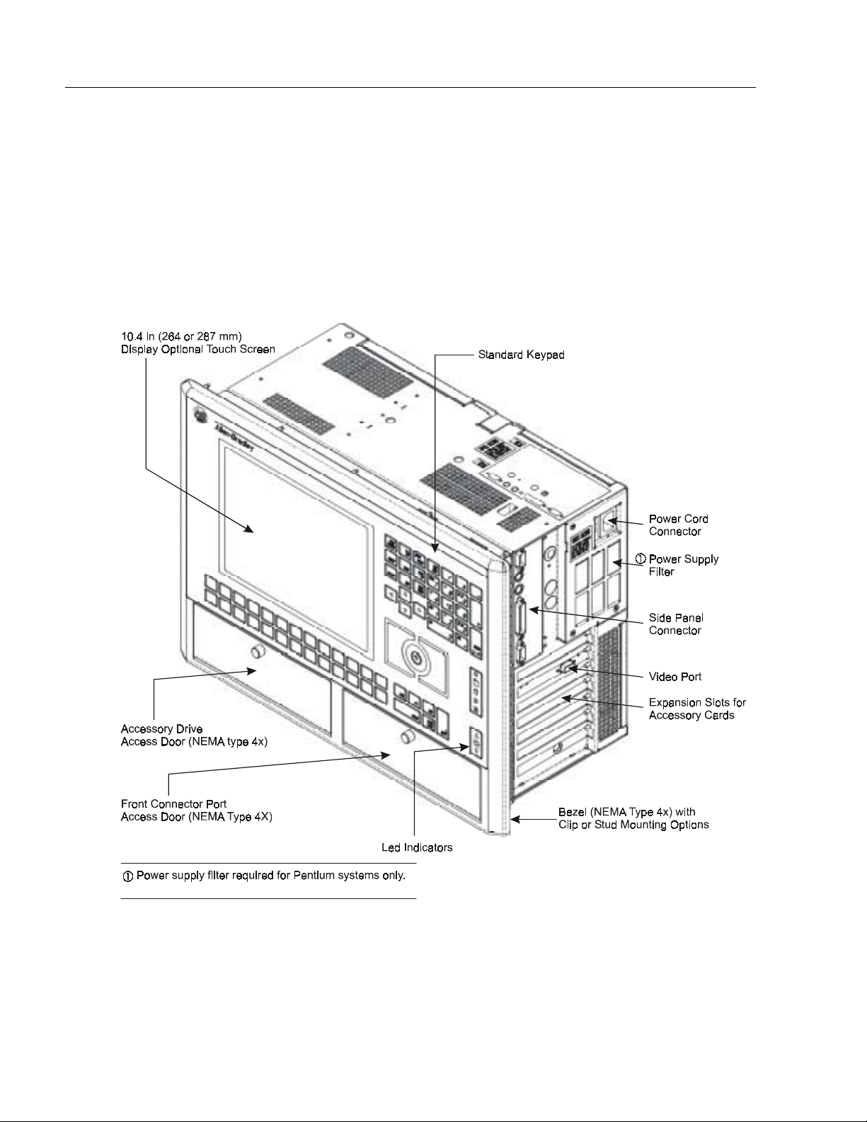
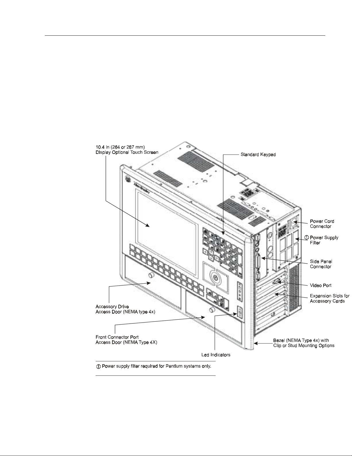
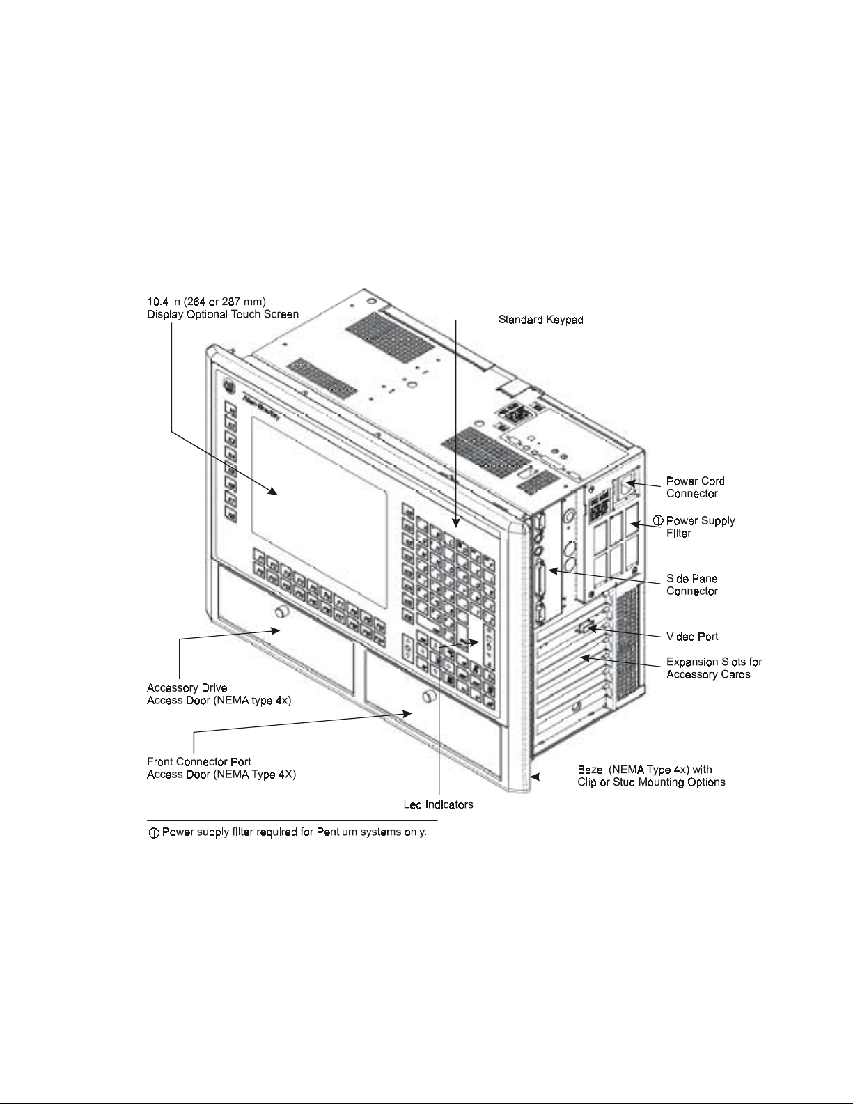
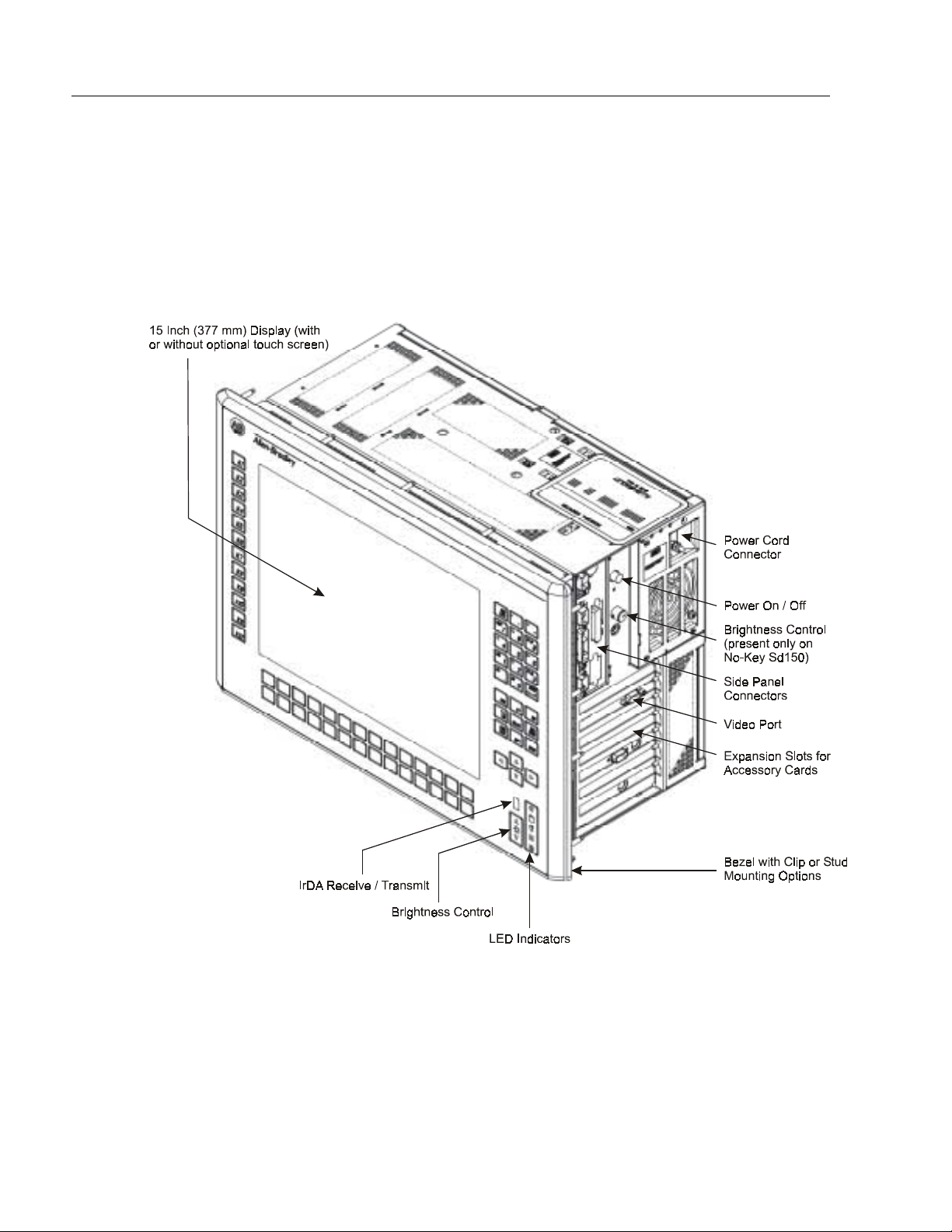
System Features 1–3
Common 6180 Computer Features
Figure 1- 1
Publication 6180-6.0
Artisan Technology Group - Quality Instrumentation ... Guaranteed | (888) 88-SOURCE | www.artisantg.com
Page 15
1–4 System Features
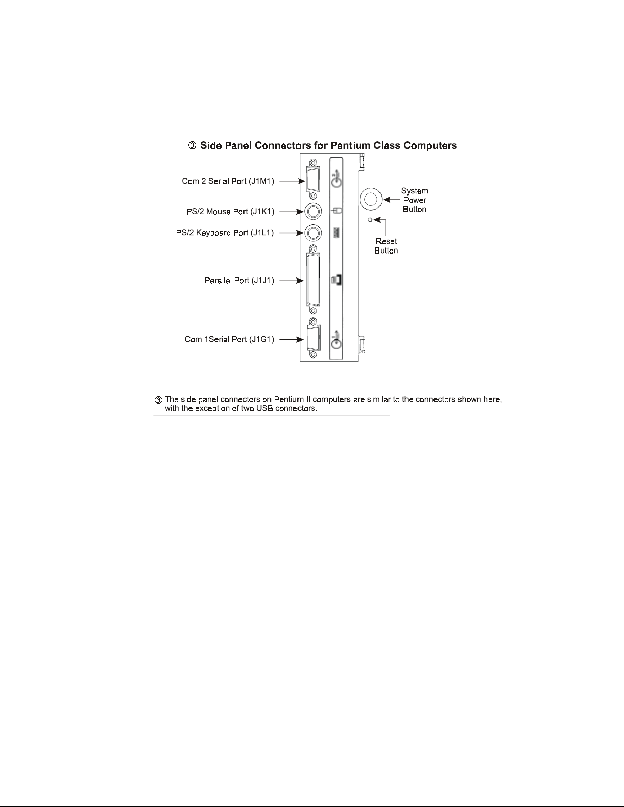
Figure 1- 2
Figure 1- 3
Need drawing for: Side Panel Connectors for Pentium II Class Computers (use illus. From Seattle II
(see engineering)
Figure 1- 4
Need drawing for: Side Panel Connectors for Pentium III/Celeron Class Computers (use illus. From
ITOX (see engineering)
Publication 6180-6.0
Artisan Technology Group - Quality Instrumentation ... Guaranteed | (888) 88-SOURCE | www.artisantg.com
Page 16
System Features 1–5
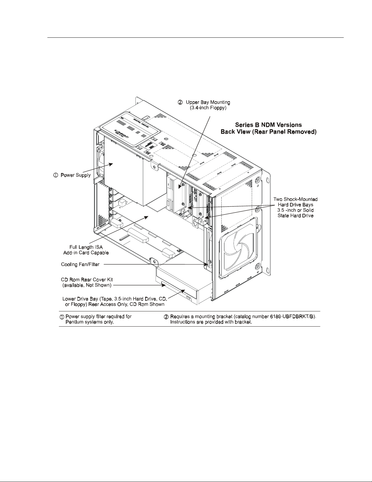
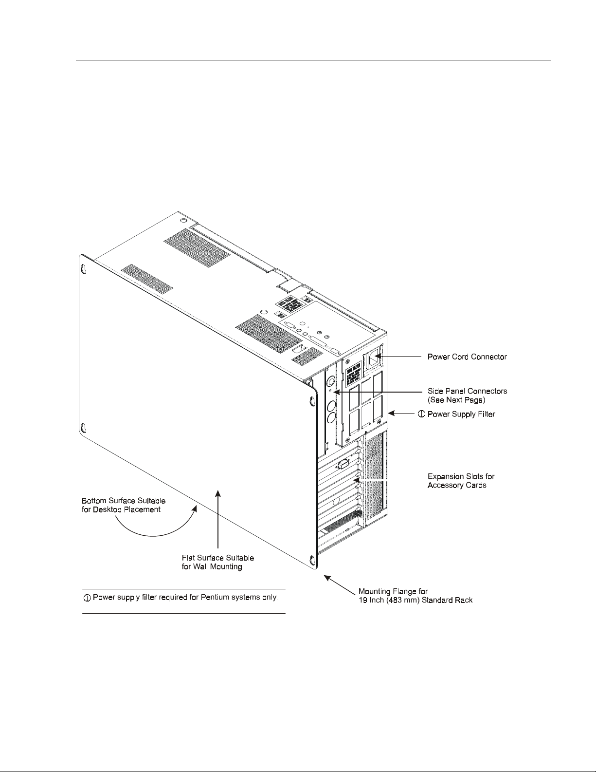
NDM Version with No Display & Metal Bezel
The following illustrations show the major features and controls of the
non–display, metal bezel versions of the 6180 Computer
(6180-xxAxxxxxxxx).
Figure 1- 5
Publication 6180-6.0
Artisan Technology Group - Quality Instrumentation ... Guaranteed | (888) 88-SOURCE | www.artisantg.com
Page 17
1–6 System Features
NDP Version with No Display & Plastic Bezel
The following illustration shows the major features and controls of the
non–display, plastic bezel versions of the 6180 Computer
(6180-xxBxxxxxxxx).
Figure 1- 6
Publication 6180-6.0
Artisan Technology Group - Quality Instrumentation ... Guaranteed | (888) 88-SOURCE | www.artisantg.com
Page 18
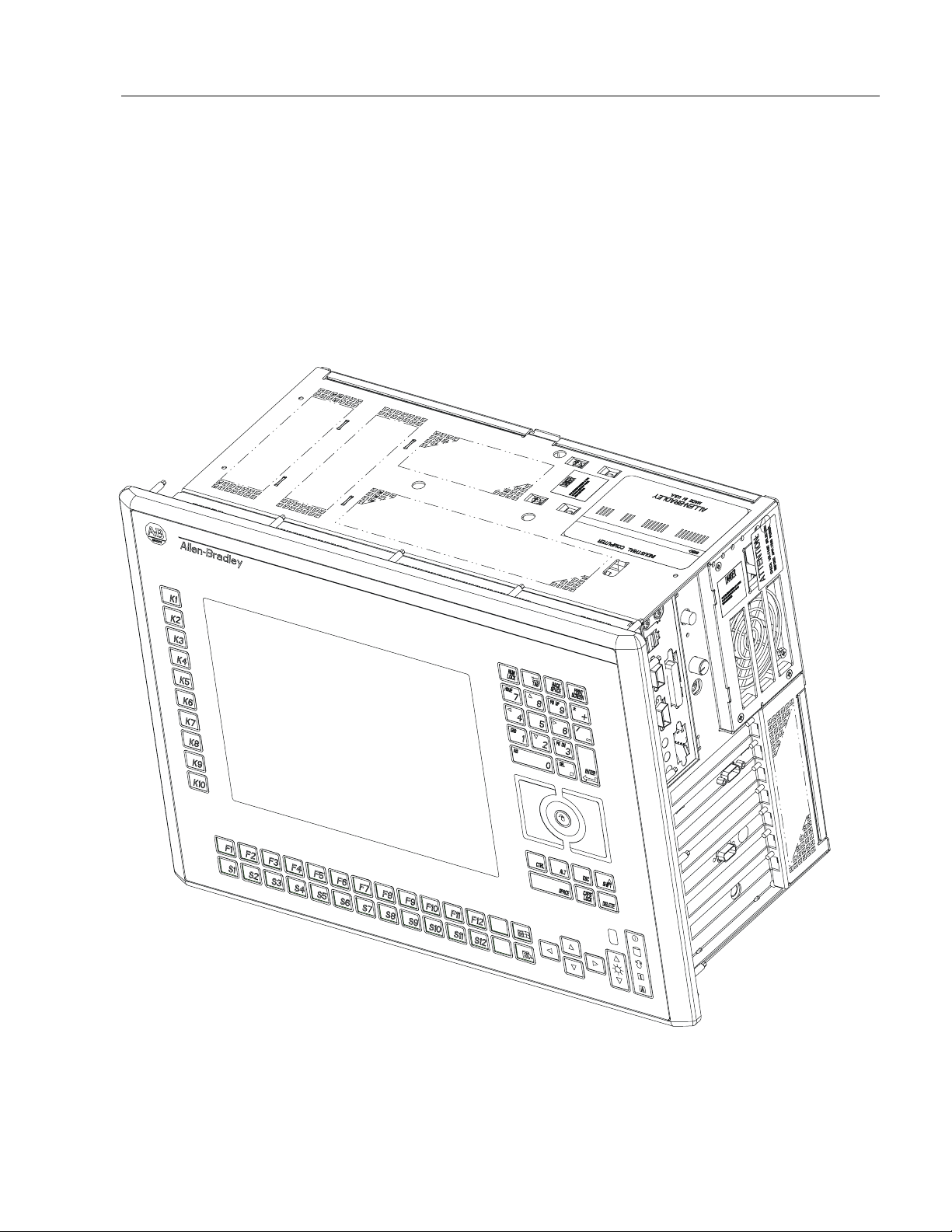
System Features 1–7
SD104 Version with
Display and 64-Key
Standard Keypad
The following illustration shows the major features and controls of the
display, plastic bezel versions of 6180 Computer (6180-xxCxxxxxxxx, xxDxxxxxxxx).
Figure 1- 7
Publication 6180-6.0
Artisan Technology Group - Quality Instrumentation ... Guaranteed | (888) 88-SOURCE | www.artisantg.com
Page 19
1–8 System Features
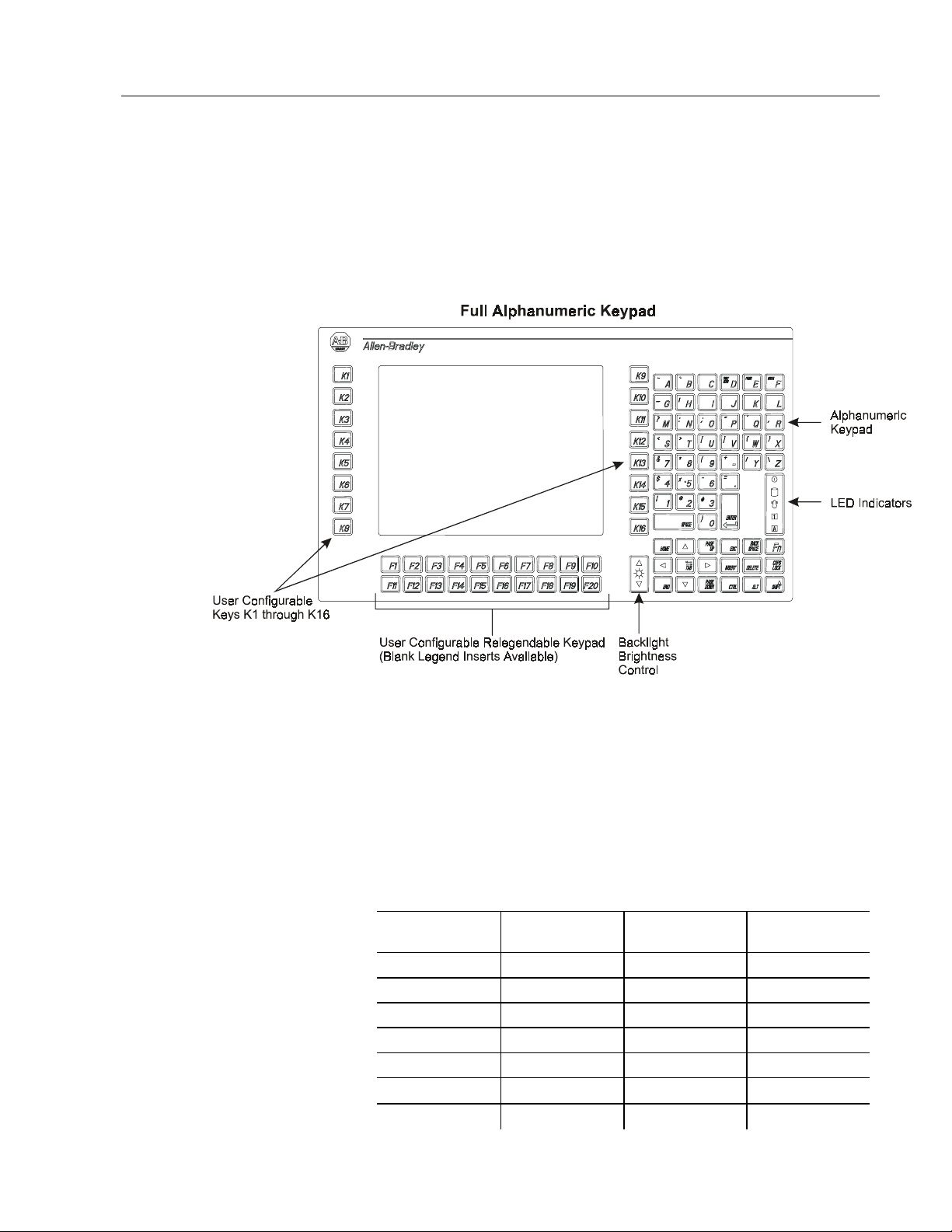
SD104 Version with Display and Full Alphanumeri c Keypad
The following illustration shows the major features and controls of the
full alphanumeric keypad versions of 6180 Computer
(6180-xxGxxxxxxxx).
Figure 1- 8
Publication 6180-6.0
Artisan Technology Group - Quality Instrumentation ... Guaranteed | (888) 88-SOURCE | www.artisantg.com
Page 20
System Features 1–9
SD121 Version with Display and 69-Key Standard Keypad
The following illustrations show the major features and controls of the
12.1 in. keypad versions of 6180 Computer (6180-xxLxxxxxxxx, 6180xxMxxxxxxxx).
Figure 1- 9
Publication 6180-6.0
Artisan Technology Group - Quality Instrumentation ... Guaranteed | (888) 88-SOURCE | www.artisantg.com
Page 21
1–10 System Features
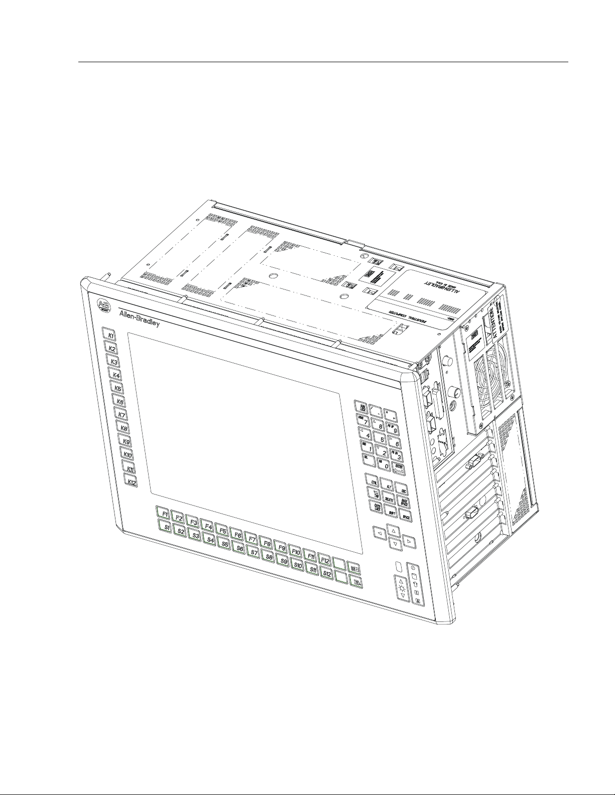
SD150 Version with Display and 70-Key Standard Keypad
The following illustration shows the major features and controls of the
70-key keypad versions of 6180 Computer (6180-xxHxxxxxxxx, xxIxxxxxxxx).
Figure 1- 10
Publication 6180-6.0
Artisan Technology Group - Quality Instrumentation ... Guaranteed | (888) 88-SOURCE | www.artisantg.com
Page 22
System Features 1–11
SD150 Version with Display and no Keypad
The following illustrations show the major features and controls of the
15 in. no keypad versions of 6180 Computer (6180-xxJxxxxxxxx, 6180xxKxxxxxxxx).
Figure 1- 11
Publication 6180-6.0
Artisan Technology Group - Quality Instrumentation ... Guaranteed | (888) 88-SOURCE | www.artisantg.com
Page 23
1–12 System Features
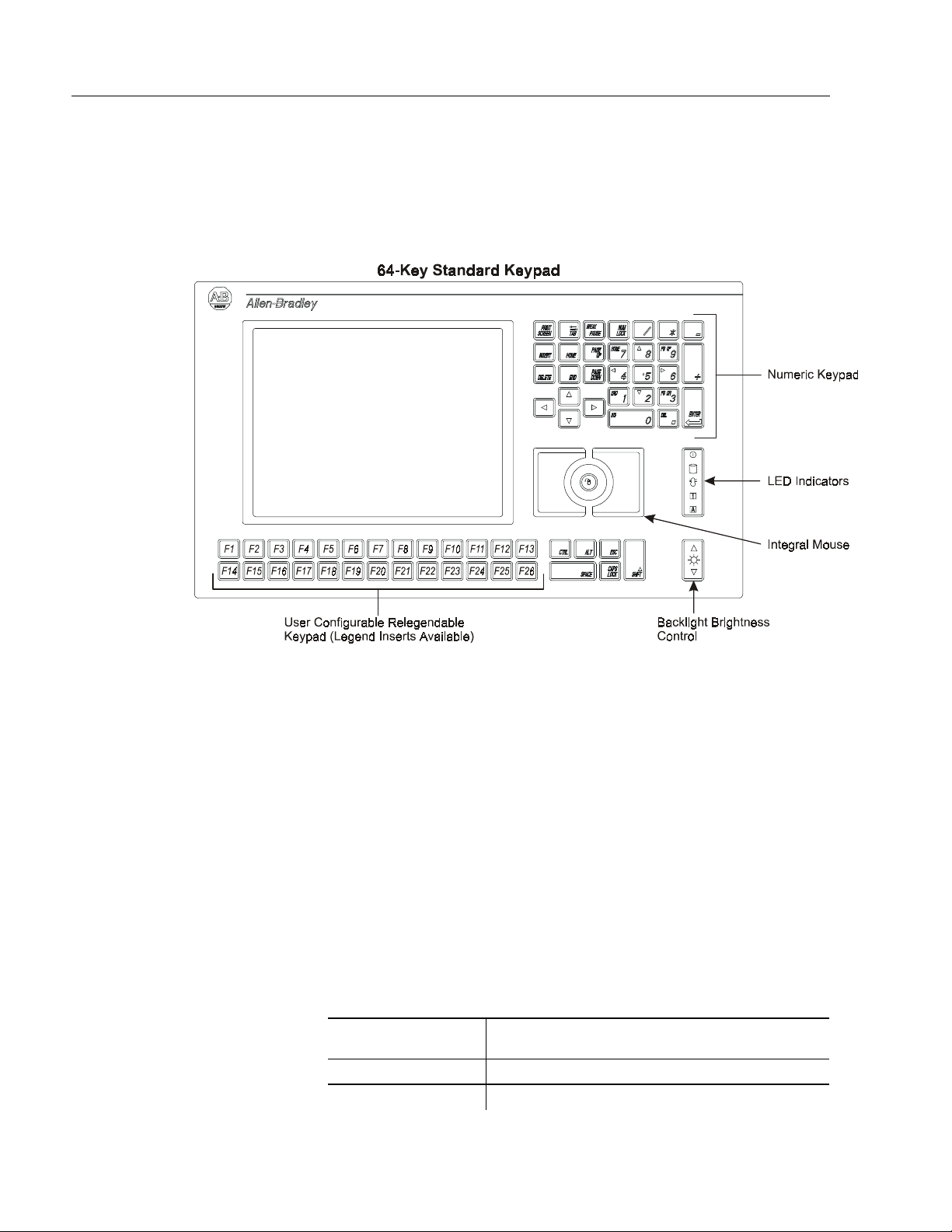
64−−−−Key Standard Keypad
The standard SD104 keypad provides integrated keyboard and mouse
control functionality.
Figure 1- 12
Numeric Keys
The NUM LOCK key allows you to use the same set of keys on the
numeric keypad for alternate Number and Cursor Control functions.
Press the NUM LOCK key to select the Number function for these keys.
The NUM LOCK LED on the keypad will be lit to indicate the Number
function is active. Press the NUM LOCK key again to select the Cursor
Control function for these keys. The NUM LOCK LED will be lit to
reflect the function.
For example, with the NUM LOCK key active (i. e. lit), the numeric
key “4” allows you to enter the number “4”. With the NUM LOCK key
inactive, the numeric key “4” allows you to move the cursor to the left
on the display.
NUM LOCK “On”
Number Function
1 End
2 Down Arrow
NUM LOCK “Off” Cursor Control Function
Publication 6180-6.0
Artisan Technology Group - Quality Instrumentation ... Guaranteed | (888) 88-SOURCE | www.artisantg.com
Page 24
System Features 1–13
NUM LOCK “On”
Number Function
3 Page Down
4 Left Arrow
5 None
6 Right Arrow
7 Home
8 Up Arrow
9 Page Up
0 Insert
. Delete
Configurable Keys
User Configurable
Key Legend
F1 F1
F2 F2
F3 F3
F4 F4
F5 F5
F6 F6
F7 F7
F8 F8
F9 F9
F10 F10
F11 F11
F12 F12
F13 Left Windows Key
F14 SHIFT + F1
F15 SHIFT + F2
F16 SHIFT + F3
F17 SHIFT + F4
F18 SHIFT + F5
F19 SHIFT + F6
F20 SHIFT + F7
F21 SHIFT + F8
F22 SHIFT + F9
F23 SHIFT + F10
NUM LOCK “Off” Cursor Control Function
Default User Defined Options
Any alphanumeric
character or string
(restricted by KCU)
Publication 6180-6.0
Artisan Technology Group - Quality Instrumentation ... Guaranteed | (888) 88-SOURCE | www.artisantg.com
Page 25

1–14 System Features
User Configurable
Key Legend
F24 SHIFT + F11
F25 SHIFT + F12
F26
Default User Defined Options
Any alphanumeric
character or string
(restricted by KCU)
Windows Application
Key
Publication 6180-6.0
Artisan Technology Group - Quality Instrumentation ... Guaranteed | (888) 88-SOURCE | www.artisantg.com
Page 26
System Features 1–15
SD104 Alphanumeric
Keypad
The SD104 alphanumeric keypad provides full keyboard functionality.
Figure 1- 13
Alphanumeric Keys
The “Fn” key allows you to use the same set of keys on the keypad for
alternate functions. The “Fn” key must be pressed and held while
pressing another key to activate the other functions.
For example, if you press the “D” key, the letter “D” is entered on the
display. If you press and hold the Fn key while pressing the “D” key,
you activate the other function for that key, which is to print the screen.
Alphanumeric
Key
A ~ W {
B ` X }
D Print Screen Y /
E Pause Z \
F Break 1 !
G
H | 3 #
Alternate
Function
−
Alphanumeric
Key
2 @
Alternate
Function
Publication 6180-6.0
Artisan Technology Group - Quality Instrumentation ... Guaranteed | (888) 88-SOURCE | www.artisantg.com
Page 27

1–16 System Features
Alphanumeric
Key
M ? 4 $
N : 5 %
O ; 6 ^
P “ 7 &
Q ‘ 8 *
R , 9 (
S < 0 )
T >
U [ . =
V ]
Alternate
Function
Alphanumeric
Key
−
Alternate
Function
+
Publication 6180-6.0
Artisan Technology Group - Quality Instrumentation ... Guaranteed | (888) 88-SOURCE | www.artisantg.com
Page 28

System Features 1–17
69−−−−Key Standard Keypad
The SD121 keypad provides keyboard functionality.
Figure 1- 14
INSERT GRAPHIC HERE
Numeric Keys
The NUM LOCK key allows you to use the same set of keys on the
numeric keypad for alternate Number and Cursor Control functions.
Press the NUM LOCK key to select the Number function for these keys.
The NUM LOCK LED on the keypad will be lit to indicate the Number
function is active. Press the NUM LOCK key again to select the Cursor
Control function for these keys. The NUM LOCK LED will be lit to
reflect the function.
For example, with the NUM LOCK key active (i. e. lit), the numeric
key “4” allows you to enter the number “4”. With the NUM LOCK key
inactive, the numeric key “4” allows you to move the cursor to the left
on the display.
NUM LOCK “On”
Number Function
1 End
2 Down Arrow
3 Page Down
4 Left Arrow
5 None
6 Right Arrow
7 Home
8 Up Arrow
9 Page Up
0 Insert
. Delete
NUM LOCK “Off” Cursor Control Function
Publication 6180-6.0
Artisan Technology Group - Quality Instrumentation ... Guaranteed | (888) 88-SOURCE | www.artisantg.com
Page 29

1–18 System Features
Configurable Keys
User Configurable
Key Legend
K1 F1
K2 F2
K3 F3
K4 F4
K5 F5
K6 F6
K7 F7
K8 F8
K9 F9
K10 F10
A A
B B
C C
D D
E E
F F
G G
H H
I I
J J
K K
L L
M M
N N
O O
P P
Q Q
R R
S S
T T
U U
V V
W W
X X
Y Y
Z Z
Default User Defined Options
Any alphanumeric
character or string
(restricted by KCU)
Publication 6180-6.0
Artisan Technology Group - Quality Instrumentation ... Guaranteed | (888) 88-SOURCE | www.artisantg.com
Page 30

System Features 1–19
User Configurable
Key Legend
Windows Logo Left Windows Key
Windows App
Windows Application
Default User Defined Options
Any alphanumeric
Key
character or string
(restricted by KCU)
Publication 6180-6.0
Artisan Technology Group - Quality Instrumentation ... Guaranteed | (888) 88-SOURCE | www.artisantg.com
Page 31

1–20 System Features
70−−−−Key Standard Keypad
The SD150 keypad provides keyboard functionality.
Figure 1- 15
The NUM LOCK key allows you to use the same set of keys on the
numeric keypad for alternate Number and Cursor Control functions.
Press the NUM LOCK key to select the Number function for these keys.
The NUM LOCK LED on the keypad will be lit to indicate the Number
function is active. Press the NUM LOCK key again to select the Cursor
Control function for these keys. The NUM LOCK LED will be lit to
reflect the function.
For example, with the NUM LOCK key active (i. e. lit), the numeric
key “4” allows you to enter the number “4”. With the NUM LOCK key
inactive, the numeric key “4” allows you to move the cursor to the left
on the display.
NUM LOCK “On”
Number Function
1 End
2 Down Arrow
NUM LOCK “Off” Cursor Control Function
Publication 6180-6.0
Artisan Technology Group - Quality Instrumentation ... Guaranteed | (888) 88-SOURCE | www.artisantg.com
Page 32

System Features 1–21
NUM LOCK “On”
Number Function
3 Page Down
4 Left Arrow
5 None
6 Right Arrow
7 Home
8 Up Arrow
9 Page Up
0 Insert
. Delete
Configurable Keys
User Configurable
Key Legend
K1 F1
K2 F2
K3 F3
K4 F4
K5 F5
K6 F6
K7 F7
K8 F8
K9 F9
K10 F10
A A
B B
C C
D D
E E
F F
G G
H H
I I
J J
K K
L L
M M
N N
NUM LOCK “Off” Cursor Control Function
Default User Defined Options
Any alphanumeric
character or string
(restricted by KCU)
Publication 6180-6.0
Artisan Technology Group - Quality Instrumentation ... Guaranteed | (888) 88-SOURCE | www.artisantg.com
Page 33

1–22 System Features
User Configurable
Key Legend
O O
P P
Q Q
R R
S S
T T
U U
V V
W W
X X
Y Y
Z Z
Windows Logo Left Windows Key
Windows App
Windows Application
Default User Defined Options
Any alphanumeric
character or string
(restricted by KCU)
Key
Publication 6180-6.0
Artisan Technology Group - Quality Instrumentation ... Guaranteed | (888) 88-SOURCE | www.artisantg.com
Page 34

System Features 1–23
Configurable Keys
Re-legendable Keys
Using the Keyboard Configuration Utility software program, you can
assign alpha characters or other functions to the keys in the configurable
section of Model 6180 keypads. For more information, refer to Chapter
13, for the Keyboard Configuration Utility.
The Legend Strip Kit (Catalog No. 6189-KEYKIT1) contains legend
strips for the following computers. .
64-Key Standard Keypad
Versions with an SD104 standard keypad (6180-xxC, -xxD) are shipped
with the 26 configurable keys assigned to function keys F1 through F12,
and shifted function keys S1 through S12. Removable inserts provide
standard or custom legends for these keys.
Full Alphanumeric Keypad
Versions with an SD104 alphanumeric keypad (6180-xxG) are shipped
with the 36 configurable keys assigned to Function Keys K1 through
K16 and F1 through F20. Removable inserts provide standard or custom
legends for the F1 through F20 keys.
Keyboard Interface
Controller Card
69-Key Standard Keypad
Versions with an SD104 keypad (6180-xxL, -xxM) are shipped with the
lower 28 configurable keys assigned to function keys F1 through F12
and shifted function keys S1 through S12. Removable inserts provide
standard or custom legends for the 28 relegendable and reprogrammable
keys. (i.e. A-Z keys, Windows key, and Application key).
70-Key Keypad
Versions with an SD121 keypad (6180-xxH, -xxI) are shipped with the
lower 28 keys assigned to the A-Z keys, Windows key, and Application
key.
Removable inserts provide standard or custom legends for the 28 relegendable and re-programmable keys.
The 6180 keypad can work simultaneously with an external keyboard.
The 6180 Keyboard Interface Controller multiplexes information from
both the 6180 keypad and the external keyboard. Refer to Chapter 12,
for information on the 6189-KICxxx card.
Integral Mouse
Artisan Technology Group - Quality Instrumentation ... Guaranteed | (888) 88-SOURCE | www.artisantg.com
On the SD104 and SD121 standard keypads, the integral mouse consists
of left, right, and cursor control buttons. Control the movement of the
screen cursor by pressing the edge of the cursor button in the direction
Publication 6180-6.0
Page 35

1–24 System Features
you want the cursor to move. The integral mouse can work
simultaneously with the optional touchscreen.
Figure 1- 16
LED Indicators
Backlight Bright ness
Control <<graphics
needed>>
Indicator Color Indicates
<<graphic needed>>
<<graphic needed>>
<<graphic needed>>
<<graphic needed>>
<<graphic needed>>
Green Power On
Green Hard Drive Operating
Red
Green Num Lock On
Green Caps Lock On
Overtemperature. Temperature inside
the 6180 Computer enclosure is above
1400 F (600 C)
Use the backlight brightness control to vary the screen lighting for
optimal viewing.
On SD150 versions without keypads (6180-xxJ and 6180-xxK), a
backlight brightness adjustment knob is located on the right side of the
chassis.
Publication 6180-6.0
Artisan Technology Group - Quality Instrumentation ... Guaranteed | (888) 88-SOURCE | www.artisantg.com
Page 36

System Features 1–25
Chassis Locks
Two chassis locking holes restrict unauthorized access to the 6180
Computer internal components. Standard padlocks may be used (user
supplied).
Figure 1- 17
ATTENTION: The chassis locking hole on the bottom
of the chassis has been plugged with a steel cap for
compliance with UL 1950 fire enclosure requirements.
Removal of this plug will result in a failure to comply
with UL 1950 safety requirements. It is up to the user to
determine if removal of the plug raises fire containment
issues with individual installation(s), and to provide
suitable preventive measures as necessary.
Publication 6180-6.0
Artisan Technology Group - Quality Instrumentation ... Guaranteed | (888) 88-SOURCE | www.artisantg.com
Page 37

1–26 System Features
Publication 6180-6.0
Artisan Technology Group - Quality Instrumentation ... Guaranteed | (888) 88-SOURCE | www.artisantg.com
Page 38

Installation
Installation
InstallationInstallation
Chapter
Chapter 2
Chapter Chapter
Chapter Objectives
European Union
Compliance
Environmental
Considerations
This chapter describes installation of the 6180 Computer including how
to:
• install the 6180 Computer in a rack
• install the 6180 Computer in a panel using mounting studs
• install the 6180 Computer in a panel using mounting clips
• change the voltage input setting
The 6180 Computer meets the European Union Directive requirements
when installed within the European Union or EEA regions and has the
CE mark. A copy of the Declaration of Conformity is available at the
Rockwell Automation / Allen–Bradley Internet site: www.ab.com
Mount the 6180 Computer in a panel or enclosure to protect the internal
circuitry. Versions with a gasketed bezel meet NEMA Type 1, 12, 13
and 4/4X (indoor use) and IEC IP54, IP65 only when mounted in a panel
or enclosure having an equivalent rating. The No Display, Metal Bezel
(NDM) version has a NEMA Type 1 and IEC IP2X rating.
Allow enough room within the enclosure for adequate ventilation. Also
consider heat produced by other devices in the enclosure. The ambient
temperature around the 6180 Computer must be maintained between 5°
and 50°C (41° to 122°F). The 6180 Computer is intended for use in
Pollution Degree 2 environments.
Make sure you provide provisions for accessing the back and side panels
of the 6180 Computer to install and remove components.
The 6180 Computer must be mounted in a vertical position as illustrated
in this manual. Installing the 6180 Computer in any other orientation
may result in overheating due to improper airflow.
ATTENTION: The bottom of the chassis has a knockout
panel. This knockout was provided for special
applications with other Allen–Bradley products. Do not
remove this knockout. If the knockout is removed, the
6180 Computer will not meet UL 1950 standards for
flammability containment.
Artisan Technology Group - Quality Instrumentation ... Guaranteed | (888) 88-SOURCE | www.artisantg.com
Page 39

2–2 Installation
Mounting Hardware
The 6180 Computer is shipped with the following mounting hardware
installed on the bezel.
Item Description Quantity Use For
<<graphic
needed>>
1.265−inch long
mounting studs with
integral spacer
Self-locking nuts 18
18
Panel or enclosure
mounting
Panel, enclosure, or
rack mounting
Mounting clips can be used instead of the mounting studs and are
ordered separately.
Item Description Quantity Use For
Mounting Clips
Catalog No. 2711NP1
Each
Package
Contains
10 Clips
Panel or enclosure
mounting
Tools Required
In addition to the tools required to make the cutout, you will need the
following tools:
• 3/8 inch socket
• 14 inch (36 cm) extension rod (minimum)
• Socket driver (in/lb torque wrench recommended)
• 7/32 hex wrench
• Ruler
Publication 6180-6.0
Artisan Technology Group - Quality Instrumentation ... Guaranteed | (888) 88-SOURCE | www.artisantg.com
Page 40

Installation 2–3
Mounting Clearances
Allow adequate space for mounting, air flow, and maintenance. The
figure below shows recommended minimum clearances to other
components within the rack or enclosure.
ATTENTION: The 6180 Computer should not be
operated within a confined space of the dimensions
shown below unless adequate ventilation or other cooling
methods are used to lower the air temperature within the
enclosure.
Figure 2- 1
ATTENTION: Before installing the 6180 Computer in a
panel, check the clearances of any add–in boards. If your
system has an Ethernet card installed, the card must be
checked for clearance before installation. Failure to
follow this caution may result in damage to the 6180
Computer and/or panel.
Publication 6180-6.0
Artisan Technology Group - Quality Instrumentation ... Guaranteed | (888) 88-SOURCE | www.artisantg.com
Page 41

2–4 Installation
Mounting Dimensions
The following figures show the mounting dimensions.
Versions with a Metal Bezel (No Display)
Figure 2- 2
Publication 6180-6.0
Artisan Technology Group - Quality Instrumentation ... Guaranteed | (888) 88-SOURCE | www.artisantg.com
Page 42

Installation 2–5
Figure 2- 3
Publication 6180-6.0
Artisan Technology Group - Quality Instrumentation ... Guaranteed | (888) 88-SOURCE | www.artisantg.com
Page 43

2–6 Installation
Versions with a Plastic Bezel (With or Without Display)
Figure 2- 4
Publication 6180-6.0
Artisan Technology Group - Quality Instrumentation ... Guaranteed | (888) 88-SOURCE | www.artisantg.com
Page 44

Installation 2–7
Versions with a Plastic Bezel (With or Without Display)
Figure 2- 5
Publication 6180-6.0
Artisan Technology Group - Quality Instrumentation ... Guaranteed | (888) 88-SOURCE | www.artisantg.com
Page 45

2–8 Installation
Mounting Cutout
The following figure provides the dimensions for making the panel or
enclosure cutout. If you are using mounting clips, the mounting studs
are removed and the 18 stud holes are not necessary.
Publication 6180-6.0
Artisan Technology Group - Quality Instrumentation ... Guaranteed | (888) 88-SOURCE | www.artisantg.com
Page 46

Installation 2–9
Figure 2- 6
Publication 6180-6.0
Artisan Technology Group - Quality Instrumentation ... Guaranteed | (888) 88-SOURCE | www.artisantg.com
Page 47

2–10 Installation
Panel Mounting
(with Studs)
To install the 6180 Computer in a panel using 18 mounting studs:
ATTENTION: Disconnect all electrical power from the
panel before making cutout.
Make sure the area around the panel cutout is clear.
Take precautions so that metal cuttings do not enter any
components that are already installed in the panel.
Failure to follow these warnings may result in personal
injury or damage to the panel components.
To install the 6180 Computer in a panel using mounting studs:
1. Cut an opening in the panel using the panel cutout dimensions
provided on page 28. Carefully drill eighteen 1/4 inch (6.35 mm)
holes for studs as indicated.
2. The 18 mounting studs are factory installed. In the event studs were
removed for clip mounting, you can re–install studs using a 1/8 inch
socket on the end of the stud. Turn stud clockwise to tighten to
approximately 10 inch pounds (1.1 N•m).
Gasket
Figure 2- 7
Bezel
Mounting Studs
(Qty 18)
Spacer
Panel or Enclosure
Self-Locking Nuts
ATTENTION: Be careful not to damage the sealing
gasket when installing or removing studs. A damaged
seal may result in damage to the 6180 Computer and
other panel components due to a leaking seal.
Publication 6180-6.0
Artisan Technology Group - Quality Instrumentation ... Guaranteed | (888) 88-SOURCE | www.artisantg.com
Page 48

Installation 2–11
3. Make sure the sealing gasket is properly positioned on the terminal.
This gasket forms a compression type seal (NEMA Type 4x), do not
use sealing compounds.
4. Place the 6180 Computer in the panel cutout aligning the studs with
the mounting holes. The 6180 Computer will snap into the panel as
the temporary retaining tabs lock against the panel (see note
following).
Note:
Versions of the 6180 Computer designed for panel
mounting have metal tabs that temporarily lock the 6180
Computer against the panel. These tabs only facilitate
installation of the mounting hardware. The tabs are not
designed to provide permanent mounting.
5. Install the 18 self–locking nuts hand tight.
ATTENTION: Tighten mounting nuts to a torque of 10
inch pounds (10 inch–pounds, 1.1 N•m) to provide a
proper seal and prevent damage to the 6180 Computer.
Allen–Bradley assumes no responsibility for water or
chemical damage to the terminal or other equipment
within the enclosure because of improper installation.
6. Alternately tighten the self–locking nuts (use 3/8 inch socket) until
the 6180 Computer is held firmly against the panel (see
recommended tightening sequence below). The studs have an
integral spacer that prevents the gasket from being over–compressed.
The amount of torque required increases significantly as the gasket
reaches the proper compression. Tighten nuts to a torque of 10 inch–
pounds (1.1 N•m).
Figure 2- 8
Publication 6180-6.0
Artisan Technology Group - Quality Instrumentation ... Guaranteed | (888) 88-SOURCE | www.artisantg.com
Page 49

2–12 Installation
Panel Mounting (with
Clips)
To install the 6180 Computer in a panel using mounting clips:
ATTENTION: Disconnect all electrical power from the
panel before making cutout.
Make sure the area around the panel cutout is clear.
Take precautions so that metal cuttings do not enter any
components that are already installed in the panel.
Failure to follow these warnings may result in personal
injury or damage to the panel components.
1. Cut an opening in the panel using the panel cutout dimensions
provided on page 2-8.
2. If the mounting studs are present, they should be removed. To
remove a stud, use a 1/8 inch socket and turn counterclockwise to
remove.
ATTENTION: Be careful not to damage the sealing
gasket when installing or removing studs. A damaged
seal may result in damage to the 6180 Computer and
other panel components due to a leaking seal.
3. Make sure the 6180 Computer sealing gasket is properly positioned
on the terminal. This gasket forms a compression type seal, do not
use sealing compounds.
Publication 6180-6.0
4. Place the 6180 Computer in the panel cutout. The 6180 Computer
will snap into the panel as the temporary retaining tabs lock against
the panel (see note below).
Note:
Versions of the 6180 Computer designed for panel
mounting have metal tabs that temporarily lock the 6180
Computer against the panel. These tabs only facilitate
installation of the mounting hardware. The tabs are not
designed to provide permanent mounting.
5. Install the 10 mounting clips (Catalog No. 2711–NP1). The
mounting clips slide into the slots on the sides, top and bottom of the
6180 Computer as indicated by the arrows shown on the following
diagram (3 top, 3 bottom, 2 sides). Gradually tighten the clips one at
a time around the bezel (see tightening sequence next page). Repeat
this process at least three times
until the clips are hand tight and the
gasket is compressed uniformly against the panel.
Artisan Technology Group - Quality Instrumentation ... Guaranteed | (888) 88-SOURCE | www.artisantg.com
Page 50

Installation 2–13
Figure 2- 9
6. Tighten mounting clips to a torque of 10 inch–pounds (1.1 N•m) in
the sequence shown above. Do not over–tighten.
ATTENTION: Tighten mounting clips to a torque of 10
inch pounds (1.1 N•m) to provide a proper seal and
prevent damage to the 6180 Computer. Allen–Bradley
assumes no responsibility for water or chemical damage
to the terminal or other equipment within the enclosure
because of improper installation.
Note:
The mounting clips on the hinge side interfere with the
opening of the hinge. Remove the clips before opening the
hinge.
Publication 6180-6.0
Artisan Technology Group - Quality Instrumentation ... Guaranteed | (888) 88-SOURCE | www.artisantg.com
Page 51

2–14 Installation
Rack Mounting
The 6180 Computer mounts in a standard EIA 19 inch (48.3 cm) rack.
The 6180 Computer occupies 8U EIA units.
Rack Mounting Guidelines
Observe the following precautions before installing the 6180 Computer
in a rack:
Disconnect all electrical power from the rack before
installing the 6180 Computer.
If installing the 6180 Computer in an enclosed rack, make
sure the ambient temperature stays within 5° to 50° C
(41° to 122° F). Be aware of other nearby devices which
may raise the ambient temperature in the rack. Make sure
there is adequate room for air flow through the 6180
Computer chassis vents.
Verify that the addition of the 6180 Computer does not
cause uneven loading (instability) of the rack.
Check that the power supply limits for the rack
components will not be exceeded by the addition of the
6180 Computer.
Make sure the installation of the 6180 Computer
maintains proper earth grounding of the rack components.
The 6180 Computer requires connection to a power
source having an earth ground (three prong outlet).
Failure to follow these warnings may result in personal
injury or damage to the rack components.
Publication 6180-6.0
Artisan Technology Group - Quality Instrumentation ... Guaranteed | (888) 88-SOURCE | www.artisantg.com
Page 52

Installation 2–15
Rack Mounting Procedures
To install the Plastic Bezel versions of the 6180 Computer in a rack:
Note:
1. The 18 mounting studs are factory installed. In the event studs were
removed for clip mounting, you can re–install studs using a 1/8 inch
socket on the end of the stud. Turn stud clockwise to tighten to
approximately 10 inch pounds (1.1 N•m).
Figure 2- 10
The metal bezel versions of the 6180 Computer have
mounting holes in the bezel. User must provide rack
mounting hardware (see example illustrated next).
Connecting a Mouse &
Keypad (Side Panel)
Artisan Technology Group - Quality Instrumentation ... Guaranteed | (888) 88-SOURCE | www.artisantg.com
2. Place the 6180 Computer in the rack aligning the studs with the
mounting holes.
3. Install the 8 self–locking nuts hand tight.
4. Alternately tighten the self–locking nuts until the 6180 Computer is
held firmly against the rack. Tighten nuts to a torque of 10 inch–
pounds (1.1 N•m).
The mouse and keyboard plug directly into the side panel mouse and
keyboard ports, or the front panel connectors as shown below. When
connected to the processor board ports, it does not matter if the keyboard
Publication 6180-6.0
Page 53

2–16 Installation
and mouse cables are interchanged, the 6180 Computer will
automatically detect them.
Figure 2- 11
Publication 6180-6.0
Artisan Technology Group - Quality Instrumentation ... Guaranteed | (888) 88-SOURCE | www.artisantg.com
Important:
If the mouse and keyboard are connected to the side panel
connectors, the keypad (if present) on the front of the 6180
Computer is disabled. The mouse and keyboard jumpers
must be installed for operation of the keypad (see next
page).
Page 54

Installation 2–17
Note:
The Keyboard Interface Card (KIC) has a keyboard
connector. If you use the processor board or front panel
keyboard/ mouse connectors, the KIC keyboard port is
overridden (disabled).
Publication 6180-6.0
Artisan Technology Group - Quality Instrumentation ... Guaranteed | (888) 88-SOURCE | www.artisantg.com
Page 55

2–18 Installation
Connecting a Mouse &
Keyboard (Front Panel)
If you are using the front panel connectors, you must install jumper
cables as shown below. These jumpers route the keyboard and mouse
ports from the processor board to the front panel connectors. Make sure
the correct ports are used.
Figure 2- 12
Publication 6180-6.0
Artisan Technology Group - Quality Instrumentation ... Guaranteed | (888) 88-SOURCE | www.artisantg.com
ATTENTION: When a keyboard or mouse is connected
to the front panel connectors, you lose the NEMA 4x and
NEMA 12 rating while the access door is open.
Page 56

Installation 2–19
Note:
The Keyboard Interface Card (KIC) has a keyboard
connector. If you use the processor board or front panel
keyboard/ mouse connectors, the KIC keyboard port is
overridden (disabled).
Publication 6180-6.0
Artisan Technology Group - Quality Instrumentation ... Guaranteed | (888) 88-SOURCE | www.artisantg.com
Page 57

2–20 Installation
Indirect Motherboard
Connections
Add text……
Publication 6180-6.0
Artisan Technology Group - Quality Instrumentation ... Guaranteed | (888) 88-SOURCE | www.artisantg.com
Page 58

Installation 2–21
Power Connections (6180
AC unit)
A standard IEC 320 power cord provides power to the 6180 Computer.
The power supply input will accept 120/240V AC.
ATTENTION: If the power supply has a manual input
voltage selection switch, check voltage selection before
applying power.
ATTENTION: The power cord must be connected to an
outlet having an earth ground (three prong outlet).
Failure to follow this warning could result in severe
electrical shock.
Use the cord retainer to prevent accidental interruption of power to the
6180 Computer. Pull the cord retainer over the cord plug as shown
below.
The following illustration pertains to 6180 Computers equipped with a
Pentium Class CPU.
Figure 2- 13
1
The power cord connector is recessed on 6180 Computers equipped with a
Pentium III CPU.
Publication 6180-6.0
Artisan Technology Group - Quality Instrumentation ... Guaranteed | (888) 88-SOURCE | www.artisantg.com
Page 59

2–22 Installation
Power Connections (6180
DC unit)
Configuring the Power
Supply Jumper
A standard IEC 320 power cord??? provides power to the 6180
Computer. The power supply input will accept ?????.
The
either power up using the on/off switch, or to automatically turn on when
AC power is applied to the unit. An internal jumper on the power supply
wiring harness controls the configuration. The factory default setting
enables the on/off switch. To change the configuration, perform the
following steps:
1. Remove power from the 6180 Computer. Disconnect the power
2. Remove the 6180 Computer back cover. Locate the power supply,
3. If the power switch bypass mode is desired, then connect the white
Computer 120/240VAC power supply can be configured to
6180
cord.
and look for a single white wire not connected on the power supply
wiring harness. The white wire is shipped not connected from the
factory, because this position enables the power switch to be used.
wire to its mating connector.
4. Replace the back cover. Reconnect power to the 6180 Computer.
5. Press and hold the on/off switch for at least 10 seconds.
6. Unplug the 6180 Computer and wait 5 seconds before plugging back
in. This clears the soft-start logic on the 6180 Computer
motherboard.
7. Plug in the unit again. The on/off switch bypass mode is enabled.
When using Microsoft Windows NT, a normal shut down and power
cycle will restart the computer regardless if the computer needs the
power button turned back on; steps 2 and 3 need to return to bypass
mode. A power outage in Windows 95/98 will still automatically reboot
the computer.
Publication 6180-6.0
Artisan Technology Group - Quality Instrumentation ... Guaranteed | (888) 88-SOURCE | www.artisantg.com
Page 60

Installation 2–23
Publication 6180-6.0
Artisan Technology Group - Quality Instrumentation ... Guaranteed | (888) 88-SOURCE | www.artisantg.com
Page 61

Artisan Technology Group - Quality Instrumentation ... Guaranteed | (888) 88-SOURCE | www.artisantg.com
Page 62

Initial Operation a
Initial Operation and Setup
Initial Operation aInitial Operation a
nd Setup
nd Setupnd Setup
Chapter
Chapter 3
Chapter Chapter
Chapter Objective
Operating Objecti ves
This chapter provides information on:
• Operating recommendations
• Bootup sequence
• System reset and power on/off buttons
• System hot keys
We recommend these operating guidelines:
• Avoid turning the system on and off frequently.
• Never turn the system off when the hard drive indicator light is
illuminated.
• After shutting the system off, do not turn it back on again until the
hard drive has come to a complete stop (about 30 seconds).
• If using an external monitor, turn on the monitor first.
• Always use the proper power down procedures as required by your
operating system such as the Shut Down command in the Microsoft
Windows operating system.
• Do not operate the 6180 Computer without the back panel installed.
An electrical shock hazard exists. In addition, removing the back
panel disrupts air flow and may result in overheating. The back panel
also functions as an EMI shield.
Operator Access
Artisan Technology Group - Quality Instrumentation ... Guaranteed | (888) 88-SOURCE | www.artisantg.com
Operator access is limited to the front panel of the 6180 Computer. This
includes the display, front panel, keys, and front panel doors (accessory
drive and mouse/keyboard connectors). Access to components behind
the rack or panel that the 6180 Computer is installed in is restricted to
authorized and properly trained personnel.
ATTENTION: Operator access is limited to the front
panel controls and access doors of the 6180 Computer.
Failure to observe this caution could result in severe
electrical shock and/or damage to the 6180 Computer.
Page 63

3–2 Initial Operation and Setup
Keypad Operation
If your computer has a front panel keypad, note the following:
• Mouse and keyboard jumpers must be installed to activate the front
panel, keypad, and mouse (see page 2-17).
• The KIC card has a jumper (P1) that enables/disables the keypad.
The default position is enabled (pins 2–3 jumpered). For more
information, refer to Chapter 13, Keyboard Configuration Utility.
Publication 6180-6.0
Artisan Technology Group - Quality Instrumentation ... Guaranteed | (888) 88-SOURCE | www.artisantg.com
Page 64

Initial Operation and Setup 3–3
System Checkout
To boot up the system:
1. Apply power and press the on/off button. The 6180 Computer
performs a Power On Self Test (POST) in which it tests the
processor board, memory, keyboard, and certain peripheral devices.
2. The 6180 Computer displays the progress of the POST and
initialization of accessory devices. This display varies depending on
the system configuration and BIOS version, but will look similar to
this:
Figure 3- 1
System Reset
3. If your system does not boot up, or you notice other problems, refer
to Chapter 15, System Troubleshooting.
4. The 6180 Computer will then run any preloaded operating system
software such as Windows 95/98 or Windows NT. If no operating
system is preloaded, the following prompt is displayed:
Insert bootable media in the appropriate drive.
The three ways to reset the 6180 Computer are to:
• use the side mounted CPU reset button
• press [Ctrl] [Alt] [Delete]
Publication 6180-6.0
Artisan Technology Group - Quality Instrumentation ... Guaranteed | (888) 88-SOURCE | www.artisantg.com
Page 65

3–4 Initial Operation and Setup
• use power switch on front or side panel
After resetting, the 6180 Computer will begin the Power On Self Test
(POST). During reset, the 6180 Computer:
• clears RAM
• starts the POST
• initializes peripheral devices, such as drives and printers
• loads the operating system (if pre–loaded)
System Hot Keys
The keyboard controller supports the following hot key sequences:
Use this key
sequence:
[Ctrl][Alt][Del]* Perform a software reset of the system.
[Ctrl][Alt][+]
[Ctrl][Alt][−]
[Ctrl][Alt][Defined
in Setup]
[Ctrl][Alt][Defined
in Setup]
* May be inhibited (user configured) through KCU. The default is Ctrl-Act-Del
enabled.
Set the system to turbo mode (Default setting). In turbo
mode, the system bootup occurs at full speed.
Switching to turbo mode may be prohibited by the
operating system, or when the CPU is in protected mode
or virtual x86 mode under DOS.
Set the system to deturbo mode. In deturbo mode, the
system operates at a slower speed (emulating a 23 MHz
AT).
Enter energy saving standby mode. Standby mode
reduces the system’s power consumption while still
responding to external interrupts, such as FAXs or
network messages.
Any keyboard or mouse activity brings the system out of
standby mode.
The Power Management hot key is defined in the
Advanced screen of the Setup program.
Lock the keyboard (and clear the screen) until a User
Password is entered. The keyboard LEDs flash to
indicate the keyboard is locked. After entering the User
Password, you do not have to press the [Enter] key.
The security hot key is entered in the Security screen of
the Setup program.
The security hot key will not function unless a User
Password is also defined in the Security screen of the
Setup program.
To:
Publication 6180-6.0
Artisan Technology Group - Quality Instrumentation ... Guaranteed | (888) 88-SOURCE | www.artisantg.com
Page 66

Initial Operation and Setup 3–5
Legend Strip for
Configurable Keypad
The 6189-KEYKIT1 legend kit contains legend strips for the following
computers:
Computer
Catalog Number
6180-xxCxxxxxxxx
6180-xxDxxxxxxxx
6180-xxGxxxxxxxx
6180-xxLxxxxxxxx
6180-xxMxxxxxxx
6180-xxHxxxxxxxx
6180-xxIxxxxxxxx
Computer Type
6180 Industrial
Computer, 10.4 inch
Color Screen
6180 Industrial
Computer, 10.4 inch
Color Screen
6180 Industrial
Computer, 12.1 inch
Color Touchscreen
6180 Industrial
Computer, 15 inch
Color Touchscreen
Standard
Full Alphanumeric
Standard
Standard
Keypad
The 6180 Computer models 6180-xxC, -xxD, xxG (with 10.4 inch
screen) are provided with a keypad strip installed display ing function k ey
labels F1 - F12 and S1 - S12. The reverse side of this strip has labels for
letters A - Z. Custom legend strips can also be created using blank
legend labels.
The 6180 Computer models 6180-xxL and -xxM (with a 12.1 inch
screen) are provided with an alpha keypad strip installed. The reverse
side of this strip has labels for function keys F1 - F12 and S1 - S12.
The 6180 Computer models 6180-xxH and -xxI (with a 15 inch screen)
are provided with an alpha keypad strip installed. The reverse side of
this strip has labels for function keys F1 - F12 and S1 - S12.
Legend kit contents
The Legend Strip Kit (Catalog No. 61 89-KEYKIT1) contains legend
strips for both the standard and full alphanumeric keypad versions of the
6180 Computer. The standard keypad legend strips are longer than the
strips for the full alphanumeric keypad. The kit contains:
• Two preprinted legend strips for standard keypads. These strips are
preprinted on both sides. One side has function key labels. The
reverse side of this strip is preprinted with labels for letters A-Z.
• Three blank legend strips for standard keypads. The strips are blank
on both sides and may be marked for custom legends.
• Three Preprinted/Blank legend strips for full alphanumeric keypads.
These strips are preprinted on one side with function key labels Fl —
F20. The reverse side of the strips are blank for marking custom
legends.
Publication 6180-6.0
Artisan Technology Group - Quality Instrumentation ... Guaranteed | (888) 88-SOURCE | www.artisantg.com
Page 67

3–6 Initial Operation and Setup
Marking the legend strip
When custom labeling the legend strips, use an indelible type of marker.
All printing must appear within the white text areas. We recommend that
you test print the legends on a separate sheet of paper to verify that the
insert has adequate space for the legends.
To reverse or change a legend strip:
1. Carefully pull the legend strip from the left side behind the bezel.
Figure 3- 2
Publication 6180-6.0
Artisan Technology Group - Quality Instrumentation ... Guaranteed | (888) 88-SOURCE | www.artisantg.com
2. If you are using the blank legend strips, mark the legends on the matt
surfaces provided for marking.
3. Re–insert the tab into the slot. Here are some helpful hints:
• Grip the legend strip near the point where the strip enters the slot
and use short “pushes”. This helps prevent buckling of the
legend strip.
• It may be helpful to “cup” the legend strip slightly as you hold it.
This will stiffen the legend strip and also prevent buckling.
Page 68

Initial Operation and Setup 3–7
Using IrDA
Using USB
The IrDA receiver / transmitter (version 2.0 compatible) located behind
the front connector access panel or directly on the front panel overlay
(see pages 1–6 and 1−11) allows you to communicate with other devices
also having an IrDA receiver / transmitter, such as printers or note book
computers. The IrDA link has a maximum baud rate of 115
kilobytes/sec. Both devices must be no more than 1 meter apart.
Also note the following when using IrDA:
• Microsoft Windows needs to be configured for IrDA support
(software drivers loaded into operating system).
• In BIOS setup, the Serial Port 2 IR Mode (in Peripheral
Communication submenu) must be enabled.
• You must be running a software application that uses IrDA.
Some 6180 motherboards are provided with USB connectors.
The Universal Serial Bus (USB) is an external bus standard that supports
data transfer rates of 12Mbps (12 million bits per second). A single USB
port can be used to connect up to 127 peripheral devices, such as mice,
modems, and keyboards. USB also supports Plug-and-Play installation
and hot plugging.
Refer to the USB peripheral documentation for installing any required
software on the 6180 Computer. Microsoft Windows 95, Windows 98,
and Windows 2000 operating systems offer plug and play support for
USB devices.
Publication 6180-6.0
Artisan Technology Group - Quality Instrumentation ... Guaranteed | (888) 88-SOURCE | www.artisantg.com
Page 69

3–8 Initial Operation and Setup
Publication 6180-6.0
Artisan Technology Group - Quality Instrumentation ... Guaranteed | (888) 88-SOURCE | www.artisantg.com
Page 70

Adding and Removing System
Adding and Removing System
Adding and Removing System Adding and Removing System
Components
Components
ComponentsComponents
Chapter
Chapter 4
Chapter Chapter
Chapter Objective
Safety Precautions
This chapter describes how to remove and install:
• back panel and accessory drive cover
• add–in boards
• processor board
The 6180 Computer contains line voltages. Make sure you disconnect
all power to the 6180 Computer before performing any of the operations
described in this chapter.
ATTENTION: Disconnect all power from the 6180
Computer before removing components. Failure to
disconnect power could result in severe electrical shock
or damage to the 6180 Computer.
ATTENTION: Wear an ESD wrist strap (well grounded)
and perform work in a static safe environment.
Electrostatic discharge can damage the 6180 Computer
and components.
Artisan Technology Group - Quality Instrumentation ... Guaranteed | (888) 88-SOURCE | www.artisantg.com
Page 71

4–2 Adding and Removing System Components
Removing the Back Panel
and Accessory Drive
Cover
This section shows how to remove the back cover to access internal
components.
ATTENTION: Review safety precautions on page 4-1
before proceeding. Failure to follow proper safety
procedures could result in severe electrical shock or
damage to the 6180 Computer.
To remove the back panel:
1. Disconnect power from the 6180 Computer.
2. Loosen the 2 screws securing the back panel. The screws are
retained and cannot be removed from the panel.
Figure 4- 1
Publication 6180-6.0
Artisan Technology Group - Quality Instrumentation ... Guaranteed | (888) 88-SOURCE | www.artisantg.com
Page 72

Adding and Removing System Components 4–3
3. To re–install back panel, position back panel tabs over the chassis
and tighten the 2 screws (6-8 in./lb.)
Adding and Removing
Add-in Boards
ISA compatible boards may be installed in any of the ISA slots or the
ISA/PCI shared slot. PCI compatible boards may be installed in any one
of the PCI slots or the ISA/PCI shared slot.
Note:
If a floppy or other device is installed in the lower bay, the
lower three slots are restricted to half-length cards.
Refer to the Processor Board manual for the type and number of slots
supported by your computer.
ATTENTION: Review safety precautions on page 4−1
before proceeding. Failure to follow proper safety
procedures could result in severe electrical shock or
damage to the 6180 Computer.
ATTENTION: Add-in boards may be sensitive to ESD
and require careful handling. Hold boards only by the
edges, do not touch connectors. After removing a board,
place the board on a flat static free surface, component
side up. Do not slide the board over any surface.
To remove a slot cover (to add a board):
Figure 4- 2
Publication 6180-6.0
Artisan Technology Group - Quality Instrumentation ... Guaranteed | (888) 88-SOURCE | www.artisantg.com
Page 73

4–4 Adding and Removing System Components
1. Remove the back panel. See page 4-2.
2. Locate the slot cover you want to remove. We recommend that you
remove adjacent add–in boards.
3. Remove the screw securing the slot cover and remove cover.
To install a slot cover (after removing a board)
1. Insert the end of the cover into the slot in the chassis.
2. Install the screw securing the slot cover, tighten to 6–8 in–lbs (.7–.9
N•m)
To install an add–in board:
1. Remove the board from its anti–static packaging and place on a
grounded, static free surface.
2. Set any board jumpers or switches as described in the instructions for
the board.
3. Hold the board by the edges and firmly press the board into the
connector on the processor board.
Figure 4- 3
Publication 6180-6.0
Artisan Technology Group - Quality Instrumentation ... Guaranteed | (888) 88-SOURCE | www.artisantg.com
Page 74

Adding and Removing System Components 4–5
4. Align the notch in the board retainer with the threaded hole and
install the screw. Hold the notch tightly against the screw before
tightening (6-8 in./lb.).
Note:
If you do not install the retainer tight against the screw, you
may have problems inserting an adjacent board.
5. Connect any board cables (if required).
6. Install the back panel. See page 4-2.
To remove an add–in board:
1. Disconnect the cables to the Keypad Interface Card (KIC) and video
card.
2. Remove the screw securing the board retainer.
3. Hold the board at each end and carefully rock the board back and
forth until the edge connectors pull free.
Installing and Removing
the Processor Board
4. Store the board in an anti-static wrapper.
5. Remove any unused cable associated with the board.
6. Install a slot cover over the open slot.
Removal of the processor board may be required for repairs or future
board upgrades.
Refer to the Processor Board Manual for board specifications.
ATTENTION: Disconnect all power from the 6180
Computer before removing components. Failure to
disconnect power could result in severe electrical shock
or damage to the 6180 Computer.
Wear an ESD wrist strap (well grounded) and perform
work in a static safe environment. Electrostatic discharge
can damage the 6180 Computer and components.
To remove the processor board:
1. Remove the back panel. See page 4-2.
2. Remove the power supply. See page 9-1.
3. Remove all add-in boards. See page 4-7.
Publication 6180-6.0
Artisan Technology Group - Quality Instrumentation ... Guaranteed | (888) 88-SOURCE | www.artisantg.com
Page 75

4–6 Adding and Removing System Components
Figure 4- 4
4. Disconnect the hard drive IDE cable connector.
5. Disconnect the floppy drive connector.
6. Disconnect the front header panel connector.
7. The side board (shown previous page) restricts access to the upper
left mounting screw of the processor board. Remove the 3 screws
that secure the board, you do not need to unplug any connectors from
the side board. Gently move the side board to allow access to the
processor board (upper left) mounting screw.
8. Remove the screws that secure the processor board and remove the
board. Place board in an anti–static wrapper.
Publication 6180-6.0
Artisan Technology Group - Quality Instrumentation ... Guaranteed | (888) 88-SOURCE | www.artisantg.com
Page 76

Adding and Removing System Components 4–7
Figure 4- 5
!!emove!seven!screws
at these locations.
!!he!!entium!
motherboard is
shown. The
Pentium II
motherboard
uses ten screws.
To install the processor board:
1. Position the board in the chassis and align the screw holes with the
stand–off spacers on the chassis.
2. Secure the processor board with the 6 screws (shown above).
Tighten screws to 6–8 inch–pounds (.7 to .9 N•m).
3. Secure the side board with the 3 m ounting screws. Tighten screws to
6–8 inch–pounds (.7 to .9 N•m).
4. Connect all cables and connectors including the IDE drive cable and
front header panel connectors.
5. Install all add–in boards. See page 4-7.
Publication 6180-6.0
Artisan Technology Group - Quality Instrumentation ... Guaranteed | (888) 88-SOURCE | www.artisantg.com
Page 77

4–8 Adding and Removing System Components
6. Install the power supply. See Chapter 9.
7. Install the back panel. See page 4-x.
Publication 6180-6.0
Artisan Technology Group - Quality Instrumentation ... Guaranteed | (888) 88-SOURCE | www.artisantg.com
Page 78

Adding and Removing Memory
Adding and Removing Memory
Adding and Removing MemoryAdding and Removing Memory
Chapter
Chapter 5
Chapter Chapter
Chapter Objective
Memory Overview
This chapter describes how to remove and install memory.
Available RAM Memory
The Pentium III processor board has three 168–pin sockets supporting 8
to 512 Megabytes (MB) of synchronous DRAM (SDRAM) in Dual
Inline Memory Module (DIMM) packaging format.
The ITOX P3/Celeron board supports:
• 16-512 MB using unbuffered DIMMs
The ITOX P3/Celeron board:
• Uses x64 or x72 PC-66 SDRAM DIMMs for 66 Mhz FSB CPUs, or
• Uses x64 or x72 PC-100 SDRAM DIMMs for 100 Mhz FSB CPUs
• ECC supported with x72
• All DIMMs must be 3.3V
These sockets support the following DIMMs, arranged in banks 0, 1, and
2:
Pentium III
(Use gold-plated DIMMs)
Memory Module
(DIMM)
64 MegaBytes
SDRAM
128 MegaBytes
SDRAM
The minimum memory size is 64MB (one 64MB DIMM). The
maximum memory size is 512MB (two 128MB and one 256MB
DIMMs) for Pentium II boards.
Catalog No. ECC/Non-ECC
6189–DIMM64 ECC 100 Mhz
6189–DIMM128 ECC 100 Mhz
Clock
Frequency
Artisan Technology Group - Quality Instrumentation ... Guaranteed | (888) 88-SOURCE | www.artisantg.com
Page 79

5–2 Adding and Removing Memory
Figure 5- 1
Both ECC and non-ECC DIMMs are supported. However, for ECC
operation to be available exclusively, ECC DIMMs (x72) must be
installed in the system. Additionally, the user must enable the ECC
Configuration feature in the CMOS setup utility. The options are “NonECC” (BIOS default) and “ECC”.
Setup Utility
Mode Option
Non-parity DIMMs No error detection N/A N/A
Parity DIMMs No error detection
Note:
Disabled Parity ECC
Single-bit error
detection
Single-bit error
correction
Double-bit error
detection
If any non–parity DIMMs are added, system parity is
disabled for all banks (even if one bank contains parity
DIMMs).
You can install from 64 MB to 512 MB of memory in the motherboard
DIMM sockets. The board has DIMM sockets arranged as banks 0, 1,
and 2. The motherboard supports the following memory features:
Publication 6180-6.0
Artisan Technology Group - Quality Instrumentation ... Guaranteed | (888) 88-SOURCE | www.artisantg.com
• 168-pin DIMMs with gold-plated contacts
Page 80

Adding and Removing Memory 5–3
• 66 or 100 Mhz SDRAM
• Non-ECC (64-bit) and ECC (72-bit) memory
• 3.3 V memory only
• Single- or double-sided DIMMs in the following sizes:
DIMM Size
16 MB 2 Mbit x 64 2 Mbit x 72
32 MB 4 Mbit x 64 4 Mbit x 72
64 MB 8 Mbit x 64 8 Mbit x 72
128 MB 16 Mbit x 64 16 Mbit x 72
Non-ECC
Configuration
ECC Configuration
When adding memory, follow these guidelines:
• You can install DIMMs in any of the three banks
• You can use different sizes of DIMMs in different banks
Guidelines for Adding and
Removing Memory
• The BIOS detects the size and type if installed memory
• For ECC operation to be available, all installed memory must be
ECC, and you must enable the ECC Configuration feature in the
Setup program. See the SE440BX Motherboard Product Guide for
more information.
When adding memory to the 6180 Computer processor board, follow
these guidelines:
• SDRAM DIMMs can be installed in one, two, or three sockets in any
order. The BIOS automatically detects memory type (i.e. ECC, nonECC), size, and speed.
• EDO DIMMs are not supported in the P3 motherboard. Do not
attempt to install these types of DIMMs.
• Use only gold-plated DIMMs in your Pentium III motherboard
• Use 168-pin (100 MHz), unbuffered SDRAM DIMMs. Both single-
and double-sided DIMMS, and registered DIMMs are supported.
• Use of serial-presence detect (SPD) DIMMs is optional, but
recommended.
Adding and Removing Memory Modules
This section gives instructions on how to add memory modules to or
remove memory modules from the 6180 Computer processor board.
Publication 6180-6.0
Artisan Technology Group - Quality Instrumentation ... Guaranteed | (888) 88-SOURCE | www.artisantg.com
Page 81

5–4 Adding and Removing Memory
Internal 6180 Computer components may be damaged by Electrostatic
Discharge (ESD). Make sure you wear a grounding strap whenever
handling circuit boards, memory modules or other internal components.
Also observe the following precautions:
• Always handle the memory cards by the ends not by the memory
module contacts.
• Store memory in an anti–static bag when it is not installed.
• Never install or remove memory with the power turned on.
To add or remove memory:
1. Disconnect power from the 6180 Computer.
ATTENTION: Wear a wrist strap (well grounded) and
perform work in a static safe environment. Electrostatic
discharge can damage the 6180 Computer and
components.
ATTENTION: Disconnect all power from the 6180
Computer before adding and removing components.
Failure to disconnect power could result in severe
electrical shock or damage to the 6180 Computer.
2. Remove the back panel of the 6180 Computer.
See the “Removing the Back Panel and Accessory Drive Cover”
section (on page 4-2 for details on how to remove the back panel.
3. Remove the 5 screws securing the power supply (see illustration,
next page).
Note:
You do not have to disconnect the power supply wiring.
Carefully position the power supply out of the way.
Carefully remove the power supply while noting how the cabling is
dressed in the unit. Also note that air diverting flap(s) are attached
to the power supply. Observe the position of the air diverting flap(s)
for later re–installation. Be careful not to damage them. Because of
the limited length of the main supply cable harness to the
motherboard, the power supply can be moved only to the point that it
just clears the edge of the chassis.
Publication 6180-6.0
Artisan Technology Group - Quality Instrumentation ... Guaranteed | (888) 88-SOURCE | www.artisantg.com
Page 82

Adding and Removing Memory 5–5
4. Holding the DIMM only by the edges, remove it from its anti–static
package.
Figure 5- 2
5. Make sure the clips at either end of the socket are pushed away from
the socket.
6. Position the DIMM above the socket. Align the two small notches in
the bottom edge of the DIMM with the keys in the socket.
7. Insert the bottom edge of the DIMM into the socket (see the figure
above).
8. When the DIMM is seated, push down on the top edge of the DIMM
until the retaining clips snap into place. Make sure the clips are
firmly in place.
9. If you installed a DIMM with ECC memory, turn on the computer
and use the ECC Configuration feature in Setup to enable ECC (see
the associated motherboard guide).
10. After the DIMMs are installed, return the power supply to its
mounting position in the chassis. Dress the cables to their original
position and ensure that the air diverting flap (s) are installed near
the processor heat sink, as originally positioned.
Publication 6180-6.0
Artisan Technology Group - Quality Instrumentation ... Guaranteed | (888) 88-SOURCE | www.artisantg.com
Page 83

5–6 Adding and Removing Memory
11. Secure the power supply and install back panel.
12. Replace the back panel. See page 4-2.
Publication 6180-6.0
Artisan Technology Group - Quality Instrumentation ... Guaranteed | (888) 88-SOURCE | www.artisantg.com
Page 84

Adding and Removing
Adding and Removing
Adding and Removing Adding and Removing
Processors
Processors
ProcessorsProcessors
Chapter
Chapter 6
Chapter Chapter
Chapter Objective
Installing and Removing
Processors
This chapter describes how to remove and install processors.
The 6180 Pentium III processor board has a 370 socket that supports a
processor upgrade migration path that includes higher performance
Pentium III processors. The 6180 Computer Pentium processor board
has a type 7 socket which supports the Pentium process.
The types of processors supported are:
• Pentium Classic-166Mhz and 233Mhz
• Slot 1-PII and PIII
• Phase 2 (or 4) PS/Finned H. S.
• Phase 3 P. S.
• Phase 4 P. S. with Puma H. S.
ATTENTION: Disconnect all power from the 6180
Computer before removing components. Failure to
disconnect power could result in severe electrical shock
or damage to the 6180 Computer.
ATTENTION: Wear a wrist strap (well grounded) and
perform work in a static safe environment. Electrostatic
discharge can damage the 6180 Computer and
components.
To remove the processor:
1. Disconnect the power from the 6180 Computer.
2. Remove the back panel. (See page 4-2).
Artisan Technology Group - Quality Instrumentation ... Guaranteed | (888) 88-SOURCE | www.artisantg.com
Page 85

6–2 Adding and Removing Processors
Figure 6- 1
3. Remove the five screws securing the power supply.
Note:
You do not have to disconnect the power supply wiring.
Carefully move the cables, and position the power supply
out of the way.
Publication 6180-6.0
Artisan Technology Group - Quality Instrumentation ... Guaranteed | (888) 88-SOURCE | www.artisantg.com
Page 86

Adding and Removing Processors 6–3
Figure 6- 2
4. Refer to the following figures (the 6180 Computer has two types of
processors). While holding the heat sink, use pliers to carefully pull
the spring clamp from the tab on the socket.
ATTENTION: The spring clip fits tightly on the socket
base. Use extreme caution when using a needle nose
pliers to remove the spring clip. Make sure pliers do not
slip and damage the processor board.
ATTENTION: The spring clamp secures the heat sink to
the processor. When the clamp is removed, the heat sink
will slide off. Make sure the heat sink does not fall onto
other components.
Publication 6180-6.0
Artisan Technology Group - Quality Instrumentation ... Guaranteed | (888) 88-SOURCE | www.artisantg.com
Page 87

6–4 Adding and Removing Processors
Figure 6- 3
5. Remove the spring clamp, heat sink, and conductive pad.
ATTENTION: When the socket lever is raised, the
processor is loose in the socket. Make sure the processor
does not drop out of the socket.
ATTENTION: Do not remove any heat conductive
grease from the conductive pad. Be careful not to damage
the conductive pad. Damage to the pad or removal of
conductive grease may result in overheating and failure of
the processor.
6. Press lightly down and out on the lever of the processor socket until
the lever can be pulled up.
7. Note the orientation of the processor and remove the processor from
the socket. Do not touch or bend the pins.
Publication 6180-6.0
Artisan Technology Group - Quality Instrumentation ... Guaranteed | (888) 88-SOURCE | www.artisantg.com
Page 88

Adding and Removing Processors 6–5
8. Place the processor in conductive foam and store in an anti–static
package.
To install the processor:
ATTENTION: Do not force the processor into the
socket. The processor will only fit in the socket one way.
Refer to the figure on the previous page for proper
orientation. Notice that both the socket and processor
have a flat corner (chamfer) that must be aligned
1. Make sure the socket locking lever is up. Position the processor in
the socket. Make sure the processor is oriented the same way as
when removed. The processor pins will not completely align with
the socket if the processor is not oriented correctly. The processor
fits easily into the socket; do not press on the processor or bend any
pins.
2. Lightly hold the processor in the socket and push down on the socket
lever until it locks in place.
3. Carefully remove the protective plastic liner on the pad.
4. Position the heat conductive pad and heat sink on the processor. The
heat sink and pad should be approximately centered over the
processor. Make sure you do not wrinkle or remove conductive
grease from thermal pad.
Note:
If the pad is damaged, it cannot be used. Either replace the
pad or use a layer of thermal grease as a substitute.
5. Place the spring clip over the heat sink. Position one end of the
spring clip under the socket tab. Use a needle nose pliers to position
the other end of spring clip under the tab on other side. On versions
with an extended heat sink, insert the spring clip into the slot on the
heat sink first and then into the slot on the opposite side (see
illustration previous page). Be careful not to let the pliers slip.
6. Secure the power supply with the same screws removed.
ATTENTION: Risk of Electrical Shock. Do not use
power supply mounting screws exceeding 0.438 inches
(11.125 mm). Screws that are longer than recommended
may come in contact with voltage sources within the
power supply.
Publication 6180-6.0
Artisan Technology Group - Quality Instrumentation ... Guaranteed | (888) 88-SOURCE | www.artisantg.com
Page 89

6–6 Adding and Removing Processors
7. Refer to the Processor Board User Manual to check system jumper
settings.
Publication 6180-6.0
Artisan Technology Group - Quality Instrumentation ... Guaranteed | (888) 88-SOURCE | www.artisantg.com
Page 90

Adding and Removing Processors 6–7
Publication 6180-6.0
Artisan Technology Group - Quality Instrumentation ... Guaranteed | (888) 88-SOURCE | www.artisantg.com
Page 91

Artisan Technology Group - Quality Instrumentation ... Guaranteed | (888) 88-SOURCE | www.artisantg.com
Page 92

Adding and Removing
Adding and Removing
Adding and Removing Adding and Removing
Removable Media
Removable Media
Removable MediaRemovable Media
Chapter
Chapter 7
Chapter Chapter
Chapter Objective
Installing and Removing
Removable Media
This chapter describes how to remove and install removable media.
Mounting Options
The following shows the three methods of mounting a floppy drive. The
front mounting option is not available for the non–display, metal bezel,
12-inch, and 15-inch versions of the 6180 Computer.
Artisan Technology Group - Quality Instrumentation ... Guaranteed | (888) 88-SOURCE | www.artisantg.com
Page 93

7–2 Adding and Removing Removable Media
Figure 7- 1
Publication 6180-6.0
Artisan Technology Group - Quality Instrumentation ... Guaranteed | (888) 88-SOURCE | www.artisantg.com
Page 94

Adding and Removing Removable Media 7–3
To remove the floppy drive or CD-ROM drive:
1. Disconnect power from the 6180 Computer.
ATTENTION: Disconnect all power before adding and
removing components. Failure to disconnect power could
result in severe electrical shock or damage to the 6180
Computer.
2. Remove the back panel. See page 4-2.
Figure 7- 2
ATTENTION: If the 6180 Computer is installed with
mounting clips, the mounting clips on the hinge side will
interfere with the opening of the hinge. Remove the
mounting clips on the hinge side before swinging chassis
away from the bezel. Failure to remove clips may
damage clips and the chassis.
Publication 6180-6.0
Artisan Technology Group - Quality Instrumentation ... Guaranteed | (888) 88-SOURCE | www.artisantg.com
Page 95

7–4 Adding and Removing Removable Media
3. From the bottom of the chassis (under the accessory drive), remove
the 4 screws that secure the accessory drive/ bracket assembly.
Figure 7- 3
4. The sequence of the following steps depends on whether the floppy
drive or CD-ROM drive is mounted to the rear or front:
• If mounted for front access, do step 6 then step 7.
• If mounted for rear access, do step 7 then step 6.
5. Disconnect the ribbon cable connector and power cable connector
from the accessory drive.
Figure 7- 4
Publication 6180-6.0
Artisan Technology Group - Quality Instrumentation ... Guaranteed | (888) 88-SOURCE | www.artisantg.com
Page 96

Adding and Removing Removable Media 7–5
6. Remove the accessory drive / bracket assembly through the back of
the chassis.
7. Remove the screws that secure the accessory drive to the bracket.
This will vary depending upon the type of drive.
Installation
Note:
To install a floppy using the lower bay mounting bracket:
1. Secure the floppy drive to the drive bracket using four screws
supplied with the bracket. Tighten screws to a torque of 6–8 in. lbs
(.7–.9 N•m).
You can also use these procedures to install a front or rear
facing CD-ROM drive (without using the mounting
bracket). The lower bay floppy drive mounting bracket and
CD-ROM drive use the same sets of chassis mounting
holes.
2. Swing open the back of the computer chassis after removing the
three bezel latching screws.
Publication 6180-6.0
Artisan Technology Group - Quality Instrumentation ... Guaranteed | (888) 88-SOURCE | www.artisantg.com
Page 97

7–6 Adding and Removing Removable Media
Figure 7- 5
3. Position the accessory drive / bracket assembly into the chassis.
Note:
For rear facing drives, you may have to remove the
panel knockout (shown above) if a rear mounted drive
was not previously installed. Insert screwdriver into
slot on knockouts and pry back and forth on knockout
to remove. Use pliers to remove the center rib between
the two knockouts.
For front facing drives, if a floppy drive was not
previously installed, you may have to replace the
floppy drive cover behind the front access door with a
cover having an opening.
Note:
You may have to remove the side panel knockout
(shown below) if a side mounted drive was not
previously installed. Insert screwdriver into slot on
knockouts and pry back and forth on knockout to
remove. Use pliers to remove the center rib between
the two knockouts.
Publication 6180-6.0
Artisan Technology Group - Quality Instrumentation ... Guaranteed | (888) 88-SOURCE | www.artisantg.com
Page 98

Adding and Removing Removable Media 7–7
4. Connect the cable connectors to the floppy drive. Connectors are
keyed so they cannot be installed backwards.
5. Align the floppy drive/bracket (or CD-ROM) and chassis mounting
holes and secure them with the 4 mounting screws provided with the
bracket (or CD-ROM). Tighten screws to a torque of 6–8 in. lbs
(.7–.9 N•m).
Figure 7- 6
6. Swing the chassis back onto the bezel and secure chassis with the
three latching screws. Tighten screws to a torque of 18–22 inch lbs
(2–2.5 N•m).
7. Install the back panel. See page 4-2.
Publication 6180-6.0
Artisan Technology Group - Quality Instrumentation ... Guaranteed | (888) 88-SOURCE | www.artisantg.com
Page 99

7–8 Adding and Removing Removable Media
8. Apply power to the 6180 Computer and v erify operation of the driv e.
You may need to edit BIOS settings to recognize the drive or to
allow the operating system to detect the new hardware.
Floppy Drive Upper Bay Mounting Bracket
The upper bay mounting bracket allows you to mount a floppy drive out
the side of the 6180 Computer chassis.
Mounting Bracket for Upper Bay Floppy Drive
(Catalog No. 6189–UBFDBRKT for Series A; Catalog No. 6189UBFDBRKTB for Series B)
Figure 7- 7
Publication 6180-6.0
Artisan Technology Group - Quality Instrumentation ... Guaranteed | (888) 88-SOURCE | www.artisantg.com
Installation
To install a floppy using the upper bay mounting bracket:
1. Secure the floppy drive to the drive bracket using four screws
supplied with the drive. Tighten screws to a torque of 6–8 in. lbs
(.7–.9 N•m).
Page 100

Adding and Removing Removable Media 7–9
Figure 7- 8
2. Remove the back panel to the 6180 Computer. See page 4-2.
3. A shorter drive cable is provided with the mounting kit for mounting
in the upper bay. Connect the cable to the floppy drive connector on
the processor board (refer to the Processor Board user manual if
necessary) and the connector on the back of the drive.
4. Position the accessory drive / bracket assembly into the chassis. The
edge of the bracket fits under the tab at the front of the chassis.
Note:
You may have to remove the side panel knockout
(shown below) if a side mounted drive was not
previously installed. Insert screwdriver into slot on
knockouts and pry back and forth on knockout to
remove. Use a pliers to remove the center rib between
the two knockouts.
ATTENTION: If knockout is removed, carefully remove
any burrs or sharp edges. Failure to remove sharp edges
could result in personal injury.
5. Align the bracket and chassis mounting hole and secure the drive /
bracket assembly with a mounting screw. Tighten screw to a torque
of 6–8 in. lbs (.7–.9 N•m).
Publication 6180-6.0
Artisan Technology Group - Quality Instrumentation ... Guaranteed | (888) 88-SOURCE | www.artisantg.com
 Loading...