

Page 1

User Manual
Original Instructions
Compact 5000 I/O Digital Modules
Catalog Numbers 5069-IA16, 5069-IB8S, 5069-IB8SK, 5069-IB16, 5069-IB16F, 5069-IB16K, 5069-IB6F-3W, 5069-OA16,
5069-OB8, 5069-OBV8S, 5069-OBV8SK, 5069-OB16, 5069-OB16F, 5069-OB16K, 5069-OW4I, 5069-OW16, 5069-OX4I
Page 2
Important User Information
Read this document and the documents listed in the additional resources section about installation, configuration, and
operation of this equipment before you install, configure, operate, or maintain this product. Users are required to
familiarize themselves with installation and wiring instructions in addition to requirements of all applicable codes, laws,
and standards.
Activities including installation, adjustments, putting into service, use, assembly, disassembly, and maintenance are
required to be carried out by suitably trained personnel in accordance with applicable code of practice.
If this equipment is used in a manner not specified by the manufacturer, the protection provided by the equipment may
be impaired.
In no event will Rockwell Automation, Inc. be responsible or liable for indirect or consequential damages resulting from
the use or application of this equipment.
The examples and diagrams in this manual are included solely for illustrative purposes. Because of the many variables and
requirements associated with any particular installation, Rockwell Automation, Inc. cannot assume responsibility or
liability for actual use based on the examples and diagrams.
No patent liability is assumed by Rockwell Automation, Inc. with respect to use of information, circuits, equipment, or
software described in this manual.
Reproduction of the contents of this manual, in whole or in part, without written permission of Rockwell Automation,
Inc., is prohibited
Throughout this manual, when necessary, we use notes to make you aware of safety considerations.
WARNING: Identifies information about practices or circumstances that can cause an explosion in a hazardous
environment, which may lead to personal injury or death, property damage, or economic loss.
ATTENTION: Identifies information about practices or circumstances that can lead to personal injury or death, property
damage, or economic loss. Attentions help you identify a hazard, avoid a hazard, and recognize the consequence.
IMPORTANT Identifies information that is critical for successful application and understanding of the product.
Labels may also be on or inside the equipment to provide specific precautions.
SHOCK HAZARD: Labels may be on or inside the equipment, for example, a drive or motor, to alert people that dangerous
voltage may be present.
BURN HAZARD: Labels may be on or inside the equipment, for example, a drive or motor, to alert people that surfaces may
reach dangerous temperatures.
ARC FLASH HAZARD: Labels may be on or inside the equipment, for example, a motor control center, to alert people to
potential Arc Flash. Arc Flash will cause severe injury or death. Wear proper Personal Protective Equipment (PPE). Follow ALL
Regulatory requirements for safe work practices and for Personal Protective Equipment (PPE).
Page 3

Digital Module Operation in
a Control System
Table of Contents
Preface . . . . . . . . . . . . . . . . . . . . . . . . . . . . . . . . . . . . . . . . . . . . . . . . . . . . . . . . . . . . . .11
Summary of Changes . . . . . . . . . . . . . . . . . . . . . . . . . . . . . . . . . . . . . . . . . . 11
Graphics Indicate Feature Support. . . . . . . . . . . . . . . . . . . . . . . . . . . . . . 12
Terminology. . . . . . . . . . . . . . . . . . . . . . . . . . . . . . . . . . . . . . . . . . . . . . . . . . 13
Additional Resources . . . . . . . . . . . . . . . . . . . . . . . . . . . . . . . . . . . . . . . . . . 14
Chapter 1
Controller and Software Compatibility . . . . . . . . . . . . . . . . . . . . . . . . . 18
Controller Compatibility . . . . . . . . . . . . . . . . . . . . . . . . . . . . . . . . . . 18
Software Compatibility . . . . . . . . . . . . . . . . . . . . . . . . . . . . . . . . . . . . 18
Types of Modules . . . . . . . . . . . . . . . . . . . . . . . . . . . . . . . . . . . . . . . . . . . . . 21
Module Overview . . . . . . . . . . . . . . . . . . . . . . . . . . . . . . . . . . . . . . . . . . . . . 22
Local I/O Modules or Remote I/O Modules. . . . . . . . . . . . . . . . . . . . . 24
Local I/O Modules . . . . . . . . . . . . . . . . . . . . . . . . . . . . . . . . . . . . . . . . 24
Remote I/O Modules . . . . . . . . . . . . . . . . . . . . . . . . . . . . . . . . . . . . . . 25
Secure Access to the System . . . . . . . . . . . . . . . . . . . . . . . . . . . . . . . . . . . . 28
Ownership. . . . . . . . . . . . . . . . . . . . . . . . . . . . . . . . . . . . . . . . . . . . . . . . . . . . 29
Multiple Owners of Compact 5000 I/O Digital
Input Modules . . . . . . . . . . . . . . . . . . . . . . . . . . . . . . . . . . . . . . . . . . . . 29
Configuration Changes in an Input Module with
Multiple Owners . . . . . . . . . . . . . . . . . . . . . . . . . . . . . . . . . . . . . . . . . . . . . . 30
Construct a System. . . . . . . . . . . . . . . . . . . . . . . . . . . . . . . . . . . . . . . . . . . . 31
Local I/O Modules . . . . . . . . . . . . . . . . . . . . . . . . . . . . . . . . . . . . . . . . 31
Remote I/O Modules . . . . . . . . . . . . . . . . . . . . . . . . . . . . . . . . . . . . . . 32
Use a 5069-ARM Address Reserve Module to
Reserve a Node Address . . . . . . . . . . . . . . . . . . . . . . . . . . . . . . . . . . . . 33
Power the Modules . . . . . . . . . . . . . . . . . . . . . . . . . . . . . . . . . . . . . . . . . . . . 34
Use a 5069-FPD Field Potential Distributor to
Establish New SA Power Buses . . . . . . . . . . . . . . . . . . . . . . . . . . . . . 35
Power Requirements When You Use Compact 5000 I/O
Safety Modules . . . . . . . . . . . . . . . . . . . . . . . . . . . . . . . . . . . . . . . . . . . . 37
Configure the Modules . . . . . . . . . . . . . . . . . . . . . . . . . . . . . . . . . . . . . . . . 40
Connections with Compact 5000 I/O Digital Modules. . . . . . . 40
Connections with Compact 5000 I/O Safety Modules. . . . . . . . 44
Requested Packet Interval . . . . . . . . . . . . . . . . . . . . . . . . . . . . . . . . . . 47
Connection Over an EtherNet/IP Network . . . . . . . . . . . . . . . . . 48
Rockwell Automation Publication 5069-UM004A-EN-P - April 2019 3
Page 4

Table of Contents
Input Module Operation . . . . . . . . . . . . . . . . . . . . . . . . . . . . . . . . . . . . . . 49
Local Compact 5000 I/O Digital Input Modules. . . . . . . . . . . . . 49
Trigger Events for Standard Input Modules. . . . . . . . . . . . . . . . . . 49
Remote Compact 5000 I/O Digital Input Modules . . . . . . . . . . 50
Output Module Operation. . . . . . . . . . . . . . . . . . . . . . . . . . . . . . . . . . . . . 51
Local Compact 5000 I/O Digital Output Modules . . . . . . . . . . . 52
Remote Compact 5000 I/O Digital Output Modules. . . . . . . . . 53
Listen Only . . . . . . . . . . . . . . . . . . . . . . . . . . . . . . . . . . . . . . . . . . . . . . . . . . . 56
Protected Operations. . . . . . . . . . . . . . . . . . . . . . . . . . . . . . . . . . . . . . . . . . 57
Considerations Specific to Safety Modules. . . . . . . . . . . . . . . . . . . . . . . 58
Overall System Safety Function . . . . . . . . . . . . . . . . . . . . . . . . . . . . . 59
Single-channel or Dual-channel Mode. . . . . . . . . . . . . . . . . . . . . . . 59
Use with Safety Controllers . . . . . . . . . . . . . . . . . . . . . . . . . . . . . . . . 60
Determine Conformity . . . . . . . . . . . . . . . . . . . . . . . . . . . . . . . . . . . . 60
Obtain Firmware . . . . . . . . . . . . . . . . . . . . . . . . . . . . . . . . . . . . . . . . . . 61
Safety Precautions . . . . . . . . . . . . . . . . . . . . . . . . . . . . . . . . . . . . . . . . . 62
Safety Application Requirements . . . . . . . . . . . . . . . . . . . . . . . . . . . 63
Safe State . . . . . . . . . . . . . . . . . . . . . . . . . . . . . . . . . . . . . . . . . . . . . . . . . 64
Configuration Signature and Ownership . . . . . . . . . . . . . . . . . . . . 65
Reset Compact 5000 I/O Safety Modules to
Out-of-Box State . . . . . . . . . . . . . . . . . . . . . . . . . . . . . . . . . . . . . . . . . . 66
Features Common to Compact
5000 I/O Digital Modules
Chapter 2
Input Module Compatibility . . . . . . . . . . . . . . . . . . . . . . . . . . . . . . . . . . . 68
Output Module Compatibility . . . . . . . . . . . . . . . . . . . . . . . . . . . . . . . . . 69
Software Configurable. . . . . . . . . . . . . . . . . . . . . . . . . . . . . . . . . . . . . . . . . 70
Module Data Quality Reporting. . . . . . . . . . . . . . . . . . . . . . . . . . . . . . . . 71
Fault and Status Reporting . . . . . . . . . . . . . . . . . . . . . . . . . . . . . . . . . . . . . 72
Module Inhibiting. . . . . . . . . . . . . . . . . . . . . . . . . . . . . . . . . . . . . . . . . . . . . 73
Electronic Keying . . . . . . . . . . . . . . . . . . . . . . . . . . . . . . . . . . . . . . . . . . . . . 74
More Information . . . . . . . . . . . . . . . . . . . . . . . . . . . . . . . . . . . . . . . . . 74
Module Firmware . . . . . . . . . . . . . . . . . . . . . . . . . . . . . . . . . . . . . . . . . . . . . 75
Producer/Consumer Communication . . . . . . . . . . . . . . . . . . . . . . . . . . 76
Use CIP Sync Time with Fast
I/O Modules. . . . . . . . . . . . . . . . . . . . . . . . . . . . . . . . . . . . . . . . . . . . . . . . . . 77
Timestamping . . . . . . . . . . . . . . . . . . . . . . . . . . . . . . . . . . . . . . . . . . . . . . . . 78
4 Rockwell Automation Publication 5069-UM004A-EN-P - April 2019
Page 5

Table of Contents
Chapter 3
Input Module Features Multiple Input Module Types . . . . . . . . . . . . . . . . . . . . . . . . . . . . . . . . . . 82
Data Transfer at RPI or Change of State . . . . . . . . . . . . . . . . . . . . . . . . 83
Software Configurable Input Filters and Delays. . . . . . . . . . . . . . . . . . 84
Compact 5000 I/O Standard Input Modules . . . . . . . . . . . . . . . . 84
Compact 5000 I/O Safety Input Modules . . . . . . . . . . . . . . . . . . . 85
Input Filter with Compact 5000 I/O Fast Input Modules. . . . . 86
Module Health Diagnostic . . . . . . . . . . . . . . . . . . . . . . . . . . . . . . . . . . . . . 87
Fault and Status Reporting . . . . . . . . . . . . . . . . . . . . . . . . . . . . . . . . . . . . . 88
Compact 5000 I/O Standard Input Modules . . . . . . . . . . . . . . . . 88
Compact 5000 I/O Safety Input Module . . . . . . . . . . . . . . . . . . . . 89
Simple Count Mode. . . . . . . . . . . . . . . . . . . . . . . . . . . . . . . . . . . . . . . . . . . 90
Sequence of Events Per Point Timestamping . . . . . . . . . . . . . . . . . . . . 91
Chatter Detection. . . . . . . . . . . . . . . . . . . . . . . . . . . . . . . . . . . . . . . . . . . . . 92
Events. . . . . . . . . . . . . . . . . . . . . . . . . . . . . . . . . . . . . . . . . . . . . . . . . . . . . . . . 93
Event Definition . . . . . . . . . . . . . . . . . . . . . . . . . . . . . . . . . . . . . . . . . . 93
Independent Point Trigger . . . . . . . . . . . . . . . . . . . . . . . . . . . . . . . . . 95
Pattern Match Trigger . . . . . . . . . . . . . . . . . . . . . . . . . . . . . . . . . . . . . 96
Additional Event Considerations . . . . . . . . . . . . . . . . . . . . . . . . . . . 97
Pulse Latching . . . . . . . . . . . . . . . . . . . . . . . . . . . . . . . . . . . . . . . . . . . . . . . . 98
Field Power Loss Detection . . . . . . . . . . . . . . . . . . . . . . . . . . . . . . . . . . . 100
Short Circuit Protection . . . . . . . . . . . . . . . . . . . . . . . . . . . . . . . . . . . . . . 102
Muting Lamp Fault and Short Circuit
Diagnostics Triggered. . . . . . . . . . . . . . . . . . . . . . . . . . . . . . . . . . . . . 103
Test Output Recovery After Overload or Short
Circuit to Ground Condition . . . . . . . . . . . . . . . . . . . . . . . . . . . . . 104
Thermal Shutoff . . . . . . . . . . . . . . . . . . . . . . . . . . . . . . . . . . . . . . . . . . . . . 105
Chapter 4
Output Module Features Multiple Output Module Types . . . . . . . . . . . . . . . . . . . . . . . . . . . . . . . 108
Module Health Diagnostics . . . . . . . . . . . . . . . . . . . . . . . . . . . . . . . . . . . 109
Data Echo . . . . . . . . . . . . . . . . . . . . . . . . . . . . . . . . . . . . . . . . . . . . . . . . . . . 110
Field Power Loss Detection . . . . . . . . . . . . . . . . . . . . . . . . . . . . . . . . . . . 111
No Load Detection. . . . . . . . . . . . . . . . . . . . . . . . . . . . . . . . . . . . . . . . . . . 113
Short Circuit Protection . . . . . . . . . . . . . . . . . . . . . . . . . . . . . . . . . . . . . . 115
Short Circuit Protection with Standard
Output Modules . . . . . . . . . . . . . . . . . . . . . . . . . . . . . . . . . . . . . . . . . 115
Short Circuit Protection with Safety Output Modules. . . . . . . 116
Other Conditions That Can Trigger the Short
Circuit Diagnostic on the 5069-OBV8S or
5069-OBV8SK Module. . . . . . . . . . . . . . . . . . . . . . . . . . . . . . . . . . . 117
Output Recovery After Overload or Short Circuit to
Ground Condition . . . . . . . . . . . . . . . . . . . . . . . . . . . . . . . . . . . . . . . 118
Rockwell Automation Publication 5069-UM004A-EN-P - April 2019 5
Page 6

Table of Contents
Thermal Shutoff . . . . . . . . . . . . . . . . . . . . . . . . . . . . . . . . . . . . . . . . . . . . . 118
Thermal Shutoff with Standard Output Modules . . . . . . . . . . . 119
Thermal Shutoff with a Safety Output Module . . . . . . . . . . . . . 120
Fault and Status Reporting . . . . . . . . . . . . . . . . . . . . . . . . . . . . . . . . . . . . 121
Compact 5000 I/O Standard Output Modules. . . . . . . . . . . . . . 121
Compact 5000 I/O Safety Output Modules . . . . . . . . . . . . . . . . 122
Output State Change Time . . . . . . . . . . . . . . . . . . . . . . . . . . . . . . . . . . . 123
Configurable Channel-level Output State in Program
Mode or Fault Mode . . . . . . . . . . . . . . . . . . . . . . . . . . . . . . . . . . . . . . . . . 123
Connection Fault Handling. . . . . . . . . . . . . . . . . . . . . . . . . . . . . . . . . . . 124
Output Behavior Immediately After a Connection
Fault . . . . . . . . . . . . . . . . . . . . . . . . . . . . . . . . . . . . . . . . . . . . . . . . . . . . 124
Fault State Duration After Connection Fault . . . . . . . . . . . . . . . 125
Final Fault State Value . . . . . . . . . . . . . . . . . . . . . . . . . . . . . . . . . . . . 125
Output State Once Connection Is Re-established . . . . . . . . . . . 125
Forcing. . . . . . . . . . . . . . . . . . . . . . . . . . . . . . . . . . . . . . . . . . . . . . . . . . . . . . 126
Enable Forces . . . . . . . . . . . . . . . . . . . . . . . . . . . . . . . . . . . . . . . . . . . . 126
Disable or Remove a Force . . . . . . . . . . . . . . . . . . . . . . . . . . . . . . . . 127
Check Force Status . . . . . . . . . . . . . . . . . . . . . . . . . . . . . . . . . . . . . . . 127
GSV Instruction. . . . . . . . . . . . . . . . . . . . . . . . . . . . . . . . . . . . . . . . . . 128
Time-scheduled Output Control . . . . . . . . . . . . . . . . . . . . . . . . . . . . . . 129
Use an MAOC Instruction with a 5069-OB16F
Output Module . . . . . . . . . . . . . . . . . . . . . . . . . . . . . . . . . . . . . . . . . . 130
Isolated and Non-isolated Varieties of Output Modules . . . . . . . . . 132
Chapter 5
Safety Module Features Safety Input Module Features . . . . . . . . . . . . . . . . . . . . . . . . . . . . . . . . . 133
Safety Application Suitability Levels. . . . . . . . . . . . . . . . . . . . . . . . 133
Use Test Output with a Safety Input . . . . . . . . . . . . . . . . . . . . . . . 135
Single-channel Mode . . . . . . . . . . . . . . . . . . . . . . . . . . . . . . . . . . . . . 137
Safety Input Fault Recovery . . . . . . . . . . . . . . . . . . . . . . . . . . . . . . . 138
Safety Input Delay Time . . . . . . . . . . . . . . . . . . . . . . . . . . . . . . . . . . 138
Muting Lamp Operation . . . . . . . . . . . . . . . . . . . . . . . . . . . . . . . . . . 141
Safety Output Module Features . . . . . . . . . . . . . . . . . . . . . . . . . . . . . . . 143
Safety Application Suitability Levels. . . . . . . . . . . . . . . . . . . . . . . . 143
Safety Output with Test Pulse . . . . . . . . . . . . . . . . . . . . . . . . . . . . . 144
Single-channel Mode . . . . . . . . . . . . . . . . . . . . . . . . . . . . . . . . . . . . . 146
Dual-channel Mode . . . . . . . . . . . . . . . . . . . . . . . . . . . . . . . . . . . . . . 147
Safety Output Fault Recovery. . . . . . . . . . . . . . . . . . . . . . . . . . . . . . 148
Fault and Status Reporting . . . . . . . . . . . . . . . . . . . . . . . . . . . . . . . . . . . . 148
6 Rockwell Automation Publication 5069-UM004A-EN-P - April 2019
Page 7

Table of Contents
Chapter 6
Configure a Standard Module Before You Begin. . . . . . . . . . . . . . . . . . . . . . . . . . . . . . . . . . . . . . . . . . . . . 150
Create a New Module . . . . . . . . . . . . . . . . . . . . . . . . . . . . . . . . . . . . . . . . 150
Discover Local I/O Modules . . . . . . . . . . . . . . . . . . . . . . . . . . . . . . 150
New Local I/O Modules . . . . . . . . . . . . . . . . . . . . . . . . . . . . . . . . . . 153
Discover Remote I/O Modules . . . . . . . . . . . . . . . . . . . . . . . . . . . . 155
New Remote I/O Module. . . . . . . . . . . . . . . . . . . . . . . . . . . . . . . . . 157
Reserve an I/O Module Slot. . . . . . . . . . . . . . . . . . . . . . . . . . . . . . . . . . . 159
Add the 5069-ARM Module to the Project . . . . . . . . . . . . . . . . . 159
Delete the 5069-ARM Module from the Project . . . . . . . . . . . . 160
Edit the Module Configuration Common Categories . . . . . . . . . . . 162
General Category. . . . . . . . . . . . . . . . . . . . . . . . . . . . . . . . . . . . . . . . . 162
Connection Category . . . . . . . . . . . . . . . . . . . . . . . . . . . . . . . . . . . . . 165
Module Info Category . . . . . . . . . . . . . . . . . . . . . . . . . . . . . . . . . . . . 166
Edit 5069-IA16 Module Configuration Categories. . . . . . . . . . . . . . 167
Points Category . . . . . . . . . . . . . . . . . . . . . . . . . . . . . . . . . . . . . . . . . . 167
Edit 5069-IB16 Module Configuration Categories. . . . . . . . . . . . . . 168
Counters Category . . . . . . . . . . . . . . . . . . . . . . . . . . . . . . . . . . . . . . . 168
Points Category . . . . . . . . . . . . . . . . . . . . . . . . . . . . . . . . . . . . . . . . . . 169
Edit 5069-IB16F Module Configuration Categories. . . . . . . . . . . . . 169
Counters Category . . . . . . . . . . . . . . . . . . . . . . . . . . . . . . . . . . . . . . . 170
Points Category . . . . . . . . . . . . . . . . . . . . . . . . . . . . . . . . . . . . . . . . . . 171
Events Category . . . . . . . . . . . . . . . . . . . . . . . . . . . . . . . . . . . . . . . . . . 173
Time Sync Category . . . . . . . . . . . . . . . . . . . . . . . . . . . . . . . . . . . . . . 175
Edit 5069-IB6F-3W Module Configuration Categories . . . . . . . . . 176
Counters Category . . . . . . . . . . . . . . . . . . . . . . . . . . . . . . . . . . . . . . . 176
Points Category . . . . . . . . . . . . . . . . . . . . . . . . . . . . . . . . . . . . . . . . . . 177
Events Category . . . . . . . . . . . . . . . . . . . . . . . . . . . . . . . . . . . . . . . . . . 179
Time Sync Category . . . . . . . . . . . . . . . . . . . . . . . . . . . . . . . . . . . . . . 181
Edit 5069-OA16 Module Configuration Categories . . . . . . . . . . . . 182
Points Category . . . . . . . . . . . . . . . . . . . . . . . . . . . . . . . . . . . . . . . . . . 182
Edit 5069-OB8 Module Configuration Categories . . . . . . . . . . . . . . 183
Points Category . . . . . . . . . . . . . . . . . . . . . . . . . . . . . . . . . . . . . . . . . . 183
Edit 5069-OB16 Module Configuration Categories. . . . . . . . . . . . . 184
Points Category . . . . . . . . . . . . . . . . . . . . . . . . . . . . . . . . . . . . . . . . . . 184
Edit 5069-OB16F Module Configuration Categories . . . . . . . . . . . 185
Points Category . . . . . . . . . . . . . . . . . . . . . . . . . . . . . . . . . . . . . . . . . . 185
Edit 5069-OW4I Module Configuration Categories . . . . . . . . . . . . 186
Points Category . . . . . . . . . . . . . . . . . . . . . . . . . . . . . . . . . . . . . . . . . . 186
Edit 5069-OW16 Module Configuration Categories. . . . . . . . . . . . 187
Points Category . . . . . . . . . . . . . . . . . . . . . . . . . . . . . . . . . . . . . . . . . . 187
Edit 5069-OX4I Module Configuration Categories. . . . . . . . . . . . . 188
Points Category . . . . . . . . . . . . . . . . . . . . . . . . . . . . . . . . . . . . . . . . . . 188
View the Module Tags . . . . . . . . . . . . . . . . . . . . . . . . . . . . . . . . . . . . . . . . 189
Rockwell Automation Publication 5069-UM004A-EN-P - April 2019 7
Page 8

Table of Contents
Configure and Replace
Safety Modules
Chapter 7
Before You Begin. . . . . . . . . . . . . . . . . . . . . . . . . . . . . . . . . . . . . . . . . . . . . 192
Create a New Module . . . . . . . . . . . . . . . . . . . . . . . . . . . . . . . . . . . . . . . . 192
New Local Safety Module . . . . . . . . . . . . . . . . . . . . . . . . . . . . . . . . . 192
New Remote I/O Module. . . . . . . . . . . . . . . . . . . . . . . . . . . . . . . . . 194
Edit the Module Configuration Common Categories . . . . . . . . . . . 196
General Category. . . . . . . . . . . . . . . . . . . . . . . . . . . . . . . . . . . . . . . . . 197
Connection Category . . . . . . . . . . . . . . . . . . . . . . . . . . . . . . . . . . . . . 200
Safety Category. . . . . . . . . . . . . . . . . . . . . . . . . . . . . . . . . . . . . . . . . . . 201
Module Info Category . . . . . . . . . . . . . . . . . . . . . . . . . . . . . . . . . . . . 202
Edit the 5069-IB8S and 5069-IB8SK Module
Configuration Categories . . . . . . . . . . . . . . . . . . . . . . . . . . . . . . . . . . . . . 203
Input Points Category . . . . . . . . . . . . . . . . . . . . . . . . . . . . . . . . . . . . 203
Test Output Points Category. . . . . . . . . . . . . . . . . . . . . . . . . . . . . . 204
Edit the 5069-OBV8S and 5069-OBV8SK Module
Points Category . . . . . . . . . . . . . . . . . . . . . . . . . . . . . . . . . . . . . . . . . . . . . . 204
View the Module Tags . . . . . . . . . . . . . . . . . . . . . . . . . . . . . . . . . . . . . . . . 205
Replace a Safety Module . . . . . . . . . . . . . . . . . . . . . . . . . . . . . . . . . . . . . . 206
Set the SNN Manually . . . . . . . . . . . . . . . . . . . . . . . . . . . . . . . . . . . . 206
Reset to Out-of-Box Configuration . . . . . . . . . . . . . . . . . . . . . . . . 208
Replace a Module in a Logix 5000 System. . . . . . . . . . . . . . . . . . . 209
Appendix A
Troubleshoot Your Module Module Status Indicator . . . . . . . . . . . . . . . . . . . . . . . . . . . . . . . . . . . . . . 212
Compact 5000 I/O Standard Input Modules
Status Indicators . . . . . . . . . . . . . . . . . . . . . . . . . . . . . . . . . . . . . . . . . . . . . 213
Compact 5000 I/O Standard Output Modules
Status Indicators . . . . . . . . . . . . . . . . . . . . . . . . . . . . . . . . . . . . . . . . . . . . . 215
Compact 5000 I/O Safety Input Module Status
Indicators. . . . . . . . . . . . . . . . . . . . . . . . . . . . . . . . . . . . . . . . . . . . . . . . . . . . 219
SA Status Indicator . . . . . . . . . . . . . . . . . . . . . . . . . . . . . . . . . . . . . . . 220
I/O Status Indicators . . . . . . . . . . . . . . . . . . . . . . . . . . . . . . . . . . . . . 220
Compact 5000 I/O Safety Output Module Status
Indicators. . . . . . . . . . . . . . . . . . . . . . . . . . . . . . . . . . . . . . . . . . . . . . . . . . . . 221
SA Status Indicator . . . . . . . . . . . . . . . . . . . . . . . . . . . . . . . . . . . . . . . 222
I/O Status Indicators . . . . . . . . . . . . . . . . . . . . . . . . . . . . . . . . . . . . . 222
Use the Logix Designer Application for Troubleshooting . . . . . . . . 223
Warning Signal in the I/O Configuration Tree . . . . . . . . . . . . . 223
Status and Fault Information in Module
Properties Categories . . . . . . . . . . . . . . . . . . . . . . . . . . . . . . . . . . . . . 224
Module and Point Diagnostics. . . . . . . . . . . . . . . . . . . . . . . . . . . . . 226
Logix Designer Application Tag Editor. . . . . . . . . . . . . . . . . . . . . 228
InternalFault Triggered on the Safety Output Module. . . . . . . . . . . 229
8 Rockwell Automation Publication 5069-UM004A-EN-P - April 2019
Page 9

Table of Contents
Appendix B
Module Tag Definitions Name Conventions. . . . . . . . . . . . . . . . . . . . . . . . . . . . . . . . . . . . . . . . . . . 232
Access the Tags . . . . . . . . . . . . . . . . . . . . . . . . . . . . . . . . . . . . . . . . . . . . . . 232
5069-IA16 Module Tags. . . . . . . . . . . . . . . . . . . . . . . . . . . . . . . . . . . . . . 233
Configuration Tags. . . . . . . . . . . . . . . . . . . . . . . . . . . . . . . . . . . . . . . 233
Input Tags . . . . . . . . . . . . . . . . . . . . . . . . . . . . . . . . . . . . . . . . . . . . . . . 234
5069-IB16 Module Tags . . . . . . . . . . . . . . . . . . . . . . . . . . . . . . . . . . . . . . 235
Configuration Tags. . . . . . . . . . . . . . . . . . . . . . . . . . . . . . . . . . . . . . . 235
Input Tags . . . . . . . . . . . . . . . . . . . . . . . . . . . . . . . . . . . . . . . . . . . . . . . 236
Output Tags . . . . . . . . . . . . . . . . . . . . . . . . . . . . . . . . . . . . . . . . . . . . . 237
5069-IB16F Module Tags. . . . . . . . . . . . . . . . . . . . . . . . . . . . . . . . . . . . . 238
Configuration Tags. . . . . . . . . . . . . . . . . . . . . . . . . . . . . . . . . . . . . . . 238
Event Input Tags . . . . . . . . . . . . . . . . . . . . . . . . . . . . . . . . . . . . . . . . . 240
Event Output Tags . . . . . . . . . . . . . . . . . . . . . . . . . . . . . . . . . . . . . . . 242
Input Tags . . . . . . . . . . . . . . . . . . . . . . . . . . . . . . . . . . . . . . . . . . . . . . . 243
Output Tags . . . . . . . . . . . . . . . . . . . . . . . . . . . . . . . . . . . . . . . . . . . . . 246
5069-IB6F-3W Module Tags. . . . . . . . . . . . . . . . . . . . . . . . . . . . . . . . . . 247
Configuration Tags. . . . . . . . . . . . . . . . . . . . . . . . . . . . . . . . . . . . . . . 247
Event Input Tags . . . . . . . . . . . . . . . . . . . . . . . . . . . . . . . . . . . . . . . . . 249
Event Output Tags . . . . . . . . . . . . . . . . . . . . . . . . . . . . . . . . . . . . . . . 251
Input Tags . . . . . . . . . . . . . . . . . . . . . . . . . . . . . . . . . . . . . . . . . . . . . . . 252
Output Tags . . . . . . . . . . . . . . . . . . . . . . . . . . . . . . . . . . . . . . . . . . . . . 255
5069-OA16 Module Tags. . . . . . . . . . . . . . . . . . . . . . . . . . . . . . . . . . . . . 256
Configuration Tags. . . . . . . . . . . . . . . . . . . . . . . . . . . . . . . . . . . . . . . 256
Input Tags . . . . . . . . . . . . . . . . . . . . . . . . . . . . . . . . . . . . . . . . . . . . . . . 257
Output Tags . . . . . . . . . . . . . . . . . . . . . . . . . . . . . . . . . . . . . . . . . . . . . 257
5069-OB8 Module Tags . . . . . . . . . . . . . . . . . . . . . . . . . . . . . . . . . . . . . . 258
Configuration Tags. . . . . . . . . . . . . . . . . . . . . . . . . . . . . . . . . . . . . . . 258
Input Tags . . . . . . . . . . . . . . . . . . . . . . . . . . . . . . . . . . . . . . . . . . . . . . . 259
Output Tags . . . . . . . . . . . . . . . . . . . . . . . . . . . . . . . . . . . . . . . . . . . . . 259
5069-OB16 Module Tags . . . . . . . . . . . . . . . . . . . . . . . . . . . . . . . . . . . . . 260
Configuration Tags. . . . . . . . . . . . . . . . . . . . . . . . . . . . . . . . . . . . . . . 260
Input Tags . . . . . . . . . . . . . . . . . . . . . . . . . . . . . . . . . . . . . . . . . . . . . . . 261
Output Tags . . . . . . . . . . . . . . . . . . . . . . . . . . . . . . . . . . . . . . . . . . . . . 261
5069-OB16F Module Tags. . . . . . . . . . . . . . . . . . . . . . . . . . . . . . . . . . . . 262
Configuration Tags. . . . . . . . . . . . . . . . . . . . . . . . . . . . . . . . . . . . . . . 262
Input Tags . . . . . . . . . . . . . . . . . . . . . . . . . . . . . . . . . . . . . . . . . . . . . . . 263
Output Tags . . . . . . . . . . . . . . . . . . . . . . . . . . . . . . . . . . . . . . . . . . . . . 265
5069-OW4I, 5069-OW16, and 5069-OX4I Module Tags. . . . . . . 266
Configuration Tags. . . . . . . . . . . . . . . . . . . . . . . . . . . . . . . . . . . . . . . 266
Input Tags . . . . . . . . . . . . . . . . . . . . . . . . . . . . . . . . . . . . . . . . . . . . . . . 267
Output Tags . . . . . . . . . . . . . . . . . . . . . . . . . . . . . . . . . . . . . . . . . . . . . 267
Rockwell Automation Publication 5069-UM004A-EN-P - April 2019 9
Page 10

Table of Contents
5069-IB8S and 5069-IB8SK Module Tags. . . . . . . . . . . . . . . . . . . . . . 268
Input Tags . . . . . . . . . . . . . . . . . . . . . . . . . . . . . . . . . . . . . . . . . . . . . . . 268
Output Tags . . . . . . . . . . . . . . . . . . . . . . . . . . . . . . . . . . . . . . . . . . . . . 269
5069-OBV8S and 5069-OBV8SK Module Tags . . . . . . . . . . . . . . . . 270
Input Tags . . . . . . . . . . . . . . . . . . . . . . . . . . . . . . . . . . . . . . . . . . . . . . . 270
Output Tags . . . . . . . . . . . . . . . . . . . . . . . . . . . . . . . . . . . . . . . . . . . . . 271
Appendix C
Application and Wiring
Examples for Safety Modules
Before You Begin. . . . . . . . . . . . . . . . . . . . . . . . . . . . . . . . . . . . . . . . . . . . . 273
5069-IB8S or 5069-IB8SK Module Wiring Diagrams . . . . . . . . . . . 274
5069-OBV8S and 5069-OBV8SK Module Wiring Diagrams . . . . 277
Bipolar Mode . . . . . . . . . . . . . . . . . . . . . . . . . . . . . . . . . . . . . . . . . . . . 277
Sourcing Mode . . . . . . . . . . . . . . . . . . . . . . . . . . . . . . . . . . . . . . . . . . . 281
Wiring Faults on Safety Modules . . . . . . . . . . . . . . . . . . . . . . . . . . . . . . 285
Appendix D
Safety Data for Safety Modules Compact 5000 I/O Safety Input Module Safety Data . . . . . . . . . . . 288
Compact 5000 I/O Safety Output Module Safety Data. . . . . . . . . . 289
Index . . . . . . . . . . . . . . . . . . . . . . . . . . . . . . . . . . . . . . . . . . . . . . . . . . . . . . . . . . . . . . .291
10 Rockwell Automation Publication 5069-UM004A-EN-P - April 2019
Page 11

Preface
This manual describes how to use Compact 5000™ I/O digital modules in
Logix 5000™ control systems.
Make sure that you are familiar with the following:
• Use of a controller in a Logix 5000 control system.
• Use of an EtherNet/IP™ network, if the digital I/O modules are
used remotely.
• Use of safety systems.
• Use Studio 5000 Logix Designer® environment.
IMPORTANT In this manual, we use standard module to indicate a standard digital I/O
module. We use safety module to indicate a safety digital I/O module.
Further, we use Compact 5000 I/O digital module to indicate when a
concept or task applies to both the standard and safety digital I/O modules.
Summary of Changes
This manual was revised to add information listed in this table. Some minor
changes were made in the manual that are not listed here.
Topic Page
Added Compact 5000 I/O conformal coated digital modules, 5069-IB16K and 5069-OB16K Throughout
Secure Access to the System 28
Configuration Changes in an Input Module with Multiple Owners 30
Use a 5069-ARM Address Reserve Module to Reserve a Node Address 33
Power Requirements When You Use Compact 5000 I/O Safety Modules 37
Connections with Compact 5000 I/O Safety Modules 44
Considerations Specific to Safety Modules 58
Use with Safety Controllers 60
Safety Precautions 62
Safety Application Requirements 63
Safe State 64
Configuration Signature and Ownership 65
Reset Compact 5000 I/O Safety Modules to Out-of-Box State 65
Safety Module Features Chapter 5, page 133
Configure and Replace Safety Modules Chapter 7, page 191
Compact 5000 I/O Safety Input Module Status Indicators 219
Compact 5000 I/O Safety Output Module Status Indicators 221
5069-IB8S and 5069-IB8SK Module Tags 268
5069-OBV8S and 5069-OBV8SK Module Tags 270
Application and Wiring Examples for Safety Modules Appendix C, page 273
Safety Data for Safety Modules Appendix D, page 287
Rockwell Automation Publication 5069-UM004A-EN-P - April 2019 11
Page 12
Preface
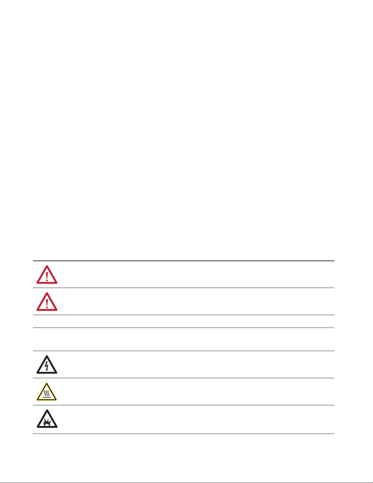
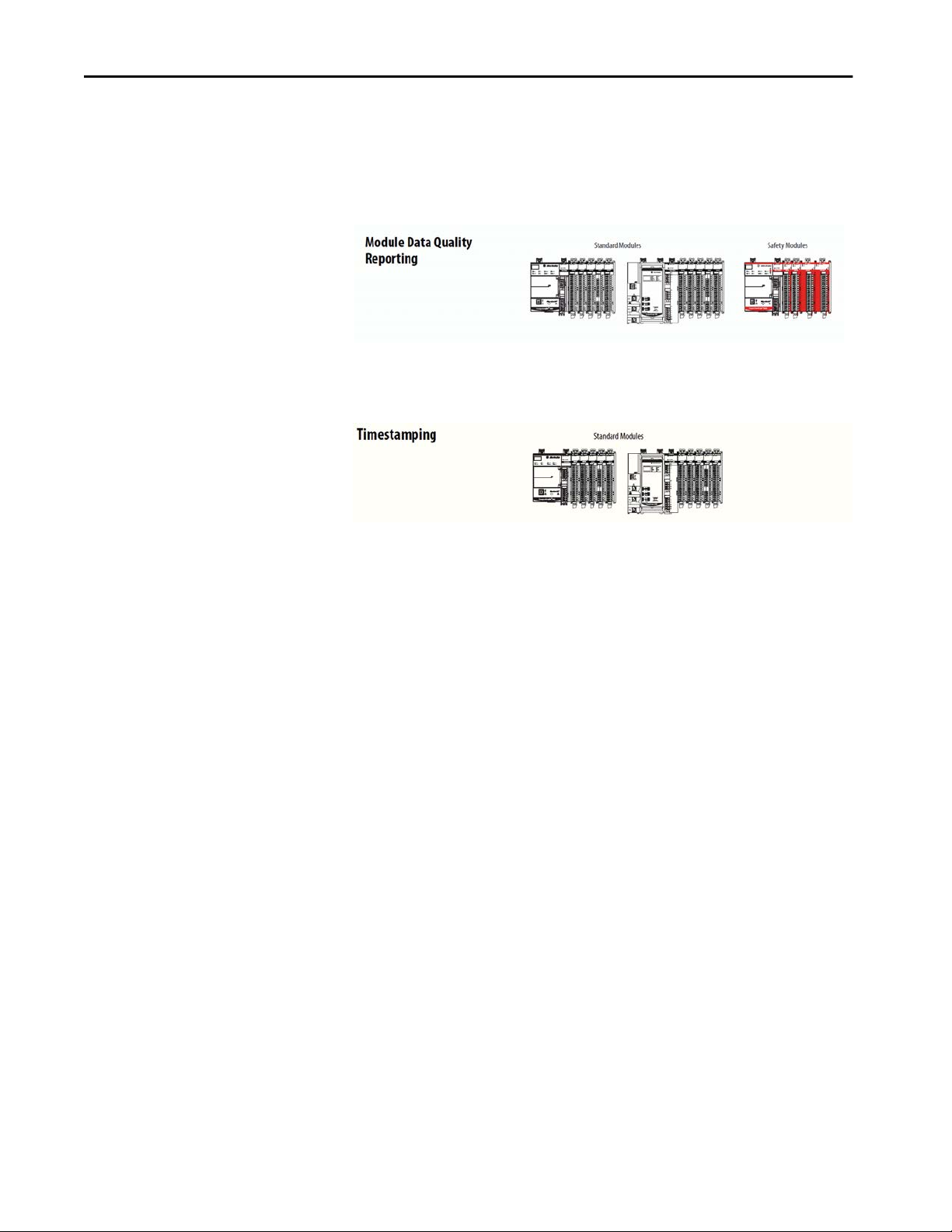
Graphics Indicate Feature Support
Throughout this manual, graphics appear with section titles to indicate the
digital I/O modules that support the feature that is described in that section.
If both standard and safety modules support a feature, you see icons for
both types.
If only one type of module, standard or safety, supports a feature, you see only
one type of icon.
12 Rockwell Automation Publication 5069-UM004A-EN-P - April 2019
Page 13

Preface
Terminology
The following table defines terms that are used in this manual.
Table 1 - Terminology Used throughout the Manual
Abbreviation Full Term Definition
1oo2 One out of Two Identifies the programmable electronic controller architecture.
CIP™ Common Industrial Protocol An industrial communication protocol that is used by Logix 5000-based automation systems on EtherNet/IP,
CIP Safety™ Common Industrial Protocol –
Safety Certified
— Connection Logical communication channel for communication between nodes. Connections are maintained and controlled
CL Claim Limit The maximum safety integrity level (SIL) that can be achieved.
DC Diagnostic Coverage The ratio of the detected failure rate to the total failure rate.
EN European Norm. The official European Standard.
GSV Get System Value A ladder logic instruction that retrieves specified controller status information and places it in a destination tag.
— Multicast The transmission of information from one sender to multiple receivers.
MTTF Mean Time to Failure The length of time that a device or other product is expected to remain reliable in operation.
NAT Network Address Translation The translation of an Internet Protocol (IP) address to another IP address on another network.
ODVA Open DeviceNet Vendor Association A nonprofit association of vendors that are established for the promotion of CIP networks.
PFD Probability of a dangerous failure on
demand
PFH Average frequency of a dangerous
failure per hour
PL Performance Level ISO 13849-1 safety rating.
— Proof test Periodic test that detects failures in a safety-related system so that, if necessary, the system can be restored to an
SC Systematic Capability A confidence that the systematic safety integrity meets the requirements of the specified safety integrity level
SFF Safe Failure Fraction The sum of safe failures plus the sum of dangerous detected failures divided by the sum of all failures.
SIL Safety Integrity Level A relative level of risk-reduction that is provided by a safety function, or to specify a target level of risk reduction.
SIL CL SL Claim Limit The maximum safety integrity level (SIL) that can be achieved.
SNN Safety Network Number Safety network number, which uniquely identifies a network across all networks in the safety system. You are
SRT Safety Reaction Time A consideration of delays or latencies within the safety system.
— Standard Devices or portions of devices that do not participate in the safety function.
— Unicast The transmission of information from one sender to one receiver.
ControlNet®, and DeviceNet® communication networks.
SIL-rated version of CIP.
between masters and slaves.
The average probability of a system to fail to perform its design function on demand.
The probability of a system to have a dangerous failure occur per hour.
as-new condition or as close as practical to this condition.
(SIL). (from IEC 61508-4)
responsible for assigning a unique number for each safety network or safety subnet within a system.
Rockwell Automation Publication 5069-UM004A-EN-P - April 2019 13
Page 14

Preface
Additional Resources
The following resources contain information about related products from
Rockwell Automation.
Table 2 - Additional Resources to Use with Compact 5000 I/O Digital Modules
Resource Description
Compact 5000 I/O Digital 16-point Sinking Input
Modules Installation Instructions, publication
5069-IN004
Compact 5000 I/O Digital 3-wire Sinking Input Module
Installation Instructions, publication
Compact 5000 I/O Digital 16-point Sourcing Output
Modules Installation Instructions, publication
5069-IN007
Compact 5000 I/O Digital 4-point Isolated Relay Output
Module Installation Instructions, publication
5069-IN008
Compact 5000 I/O Digital 4-point Isolated Normallyopen/Normally-closed Relay Output Module Installation
Instructions, publication
Compact 5000 I/O Analog 8-channel Current/Vole Input
Module Installation Instructions, publication
5069-IN010
Compact 5000 I/O Analog 4-channel Current/Vole/RTD/
Thermocouple Input Module Installation Instructions,
publication
Compact 5000 I/O Analog Current/Vole Output Modules
Installation Instructions, publication
Compact 5000 I/O Digital 16-point 120/240V AC Input
Module Installation Instructions, publication
5069-IN015
Compact 5000 I/O Digital 16-point 120/240V AC Output
Module Installation Instructions, publication
5069-IN016
Compact 5000 I/O Digital 8-point 24V DC Output Module
Installation Instructions, publication
Compact 5000 I/O Digital 16-point Relay Output Module
Installation Instructions, publication
Compact 5000 I/O Safety Sinking Input Module
Installation Instructions, publication
Compact 5000 I/O Safety Output Module Installation
Instructions, publication
Compact 5000 I/O Field Potential Distributor Installation
Instructions, publication
Compact 5000 I/O Address Reserve Module Installation
Instructions, publication
Compact 5000 I/O EtherNet/IP Adapter Installation
Instructions, publication
Compact 5000 I/O Modules and EtherNet/IP Adapter
Technical Data, publication
Compact 5000 I/O Analog Modules User Manual,
publication
Compact 5000 I/O High-speed Counter Module User
Manual, publication
5069-IN011
5069-UM005
5069-IN009
5069-IN021
5069-IN001
5069-IN002
5069-IN003
5069-UM006
5069-IN006
5069-IN012
5069-IN017
5069-IN018
5069-IN020
5069-TD001
Describes how to install and wire the 5069-IB16,
5069-IB16F, and 5069-IB16K input modules.
Describes how to install and wire the 5069-IB6F-3W
input module.
Describes how to install and wire the 5069-OB16,
5069-OB16F, and 5069-OB16K output modules.
Describes how to install and wire the 5069-OW4I output
module.
Describes how to install and wire the 5069-OX4I output
module.
Describes how to install and wire the 5069-IF8 analog
input module.
Describes how to install and wire the 5069-IY4 and
5069-IY4K analog input modules.
Describes how to install and wire the 5069-OF4,
5069-OF4K, and 5069-OF8 analog output modules.
Describes how to install and wire the 5069-IA16 input
module.
Describes how to install and wire the 5069-OA16 output
module.
Describes how to install and wire the 5069-OB8 output
module.
Describes how to install and wire the 5069-OW16
output module.
Describes how to install and wire the 5069-IB8S and
5069-IB8SK safety input module.
Describes how to install and wire the 5069-OBV8S and
5069-OBV8SK safety output modules.
Describes how to install and wire the 5069-FPD field
potential distributor.
Describes how to install the 5069-ARM address reserve
module.
Describes how to install and wire the Compact 5000 I/O
EtherNet/IP adapters.
Provides specifications, wiring diagrams, and module
block diagrams for Compact 5000 I/O modules and
EtherNet/IP adapters
Describes how to configure, operate, and troubleshoot
Compact 5000 I/O analog modules.
Describes how to configure, operate, and troubleshoot
the Compact 5000 I/O high-speed counter module.
14 Rockwell Automation Publication 5069-UM004A-EN-P - April 2019
Page 15
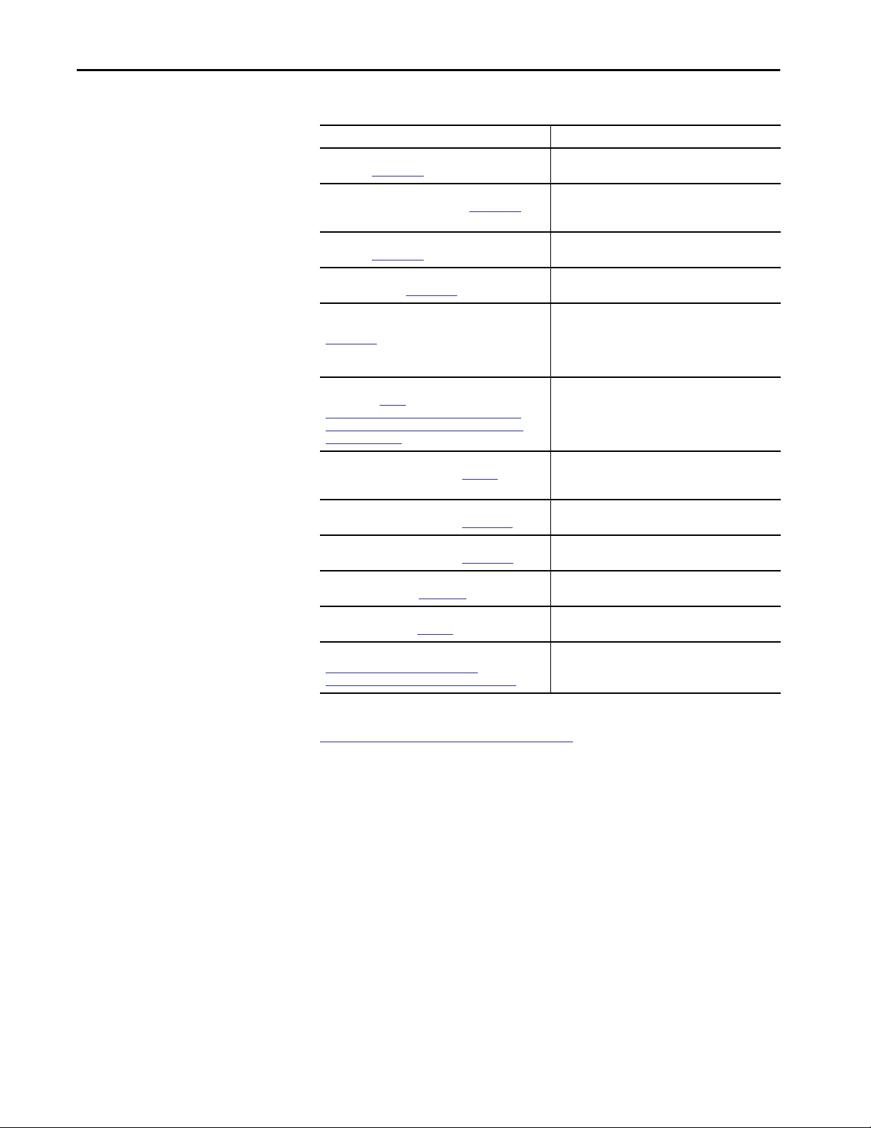
Table 2 - Additional Resources to Use with Compact 5000 I/O Digital Modules
Resource Description
Compact 5000 EtherNet/IP Adapters User Manual,
publication 5069-UM007
CompactLogix 5380 and Compact GuardLogix 5380
Controllers User Manual, publication
CompactLogix 5480 Controllers User Manual,
publication
ControlLogix 5580 and GuardLogix 5580 Controllers User
Manual, publication
GuardLogix and Compact GuardLogix 5380 Controller
Systems Safety Reference Manual, publication
1756-RM012
SISTEMA Performance Level Calculator, available for
download at:
www.marketing.rockwellautomation.com/safetysolutions/en/MachineSafety/ToolsAndDownloads/
sistema_download
Integrated Architecture and CIP Sync Configuration
Application Technique, publication
Electronic Keying in Logix5000 Control Systems
Application Technique, publication
Logix5000 Controllers Tasks, Programs, and Routines
Programming Manual, publication
Position-based Output Control with the MAOC
Instruction, publication
Industrial Automation Wiring and Grounding
Guidelines, publication
Product Certifications website,
http://www.rockwellautomation.com/
rockwellautomation/certification/overview.page
5069-UM002
1756-UM543
http://
1756-AT017
1770-4.1
5069-UM001
IA-AT003
LOGIX-AT001
1756-PM005
Describes how to configure, operate, and troubleshoot
the Compact 5000 I/O EtherNet/IP adapters.
Describes how to configure, operate, and troubleshoot
CompactLogix™ 5380 and Compact GuardLogix® 5380
controllers.
Describes how to configure, operate, and troubleshoot
CompactLogix 5480 controllers.
Describes how to configure, operate, and troubleshoot
ControlLogix® 5580 and GuardLogix 5580 controllers.
Describes requirements for achieving and maintaining
Safety Integrity Level (SIL) 2 and Performance Level (PL)
d requirements with the GuardLogix 5580 controller
system, using the Studio 5000 Logix Designer
application.
The SISTEMA tool automates calculation of the attained
Performance Level from the safety-related parts of a
machine’s control system to (EN) ISO 13849-1.
Provides information about CIP Sync™ technology and
how to synchronize clocks within the Rockwell
Automation® Integrated Architecture® system.
Describes how to use electronic keying in Logix 5000
control system applications.
Provides more information on event tasks and event
task configuration.
Describes how to configure time-scheduled output
control with the MAOC instruction.
Provides general guidelines for installing a Rockwell
Automation® industrial system.
Provides declarations of conformity, certificates, and
other certification details.
Preface
You can view or download publications at
http://literature.rockwellautomation.com/. To order paper copies of technical
documentation, contact your local Allen-Bradley distributor or Rockwell
Automation® sales representative.
Rockwell Automation Publication 5069-UM004A-EN-P - April 2019 15
Page 16

Preface
Notes:
16 Rockwell Automation Publication 5069-UM004A-EN-P - April 2019
Page 17

Chapter 1
Digital Module Operation in a Control System
Topic Page
Controller and Software Compatibility 18
Types of Modules 21
Module Overview 22
Local I/O Modules or Remote I/O Modules 24
Secure Access to the System 28
Ownership 29
Construct a System 31
Power the Modules 34
Configure the Modules 40
Input Module Operation 49
Output Module Operation 51
Listen Only 56
Protected Operations 57
Considerations Specific to Safety Modules 58
Logix 5000™ controllers use Compact 5000™ I/O digital modules to control
devices in a control system.
Compact 5000 I/O digital modules use removable terminal blocks (RTBs) to
connect field-side wiring. You use the Studio 5000 Logix Designer® application
to configure the modules.
IMPORTANT Controller and programming software compatibility requirements apply
when you use Compact 5000 I/O digital modules.
For more information on controller and software compatibility, see
Controller and Software Compatibility on page 18.
Compact 5000 I/O digital modules use the Producer/Consumer network
communication model. This communication is an intelligent data exchange
between modules and other system devices in which each module produces
data without first being polled.
Rockwell Automation Publication 5069-UM004A-EN-P - April 2019 17
Page 18
Chapter 1 Digital Module Operation in a Control System
Controller and Software Compatibility
Standard Modules
DC OUTPUT
DC INPUT
5069-IB16
SA Power MOD Power
CONTROLLER
5069-L46ERMW
UPS
R
R
OK
FAN 1
B
B
RUN
SD
F
F
FORCE
FAN 2
NET B1
B1
LINK B1
NET A1
LINK A1
NET A2
A1
LINK A2
1
2
CompactLogix 5480
A2
MP
SA
SPEED X1
LINK X1
™
Safety Modules
SIL2 CPU
5069-L3100ERMS2
ANALOG INPUT
DC INPUT
5069-IB16
DC INPUT
5069-IB16
5069-IB8S5069-IB8S
5069-OB16
DC INPUT
5069-IB16
5069-OBV8S
5069-IY4
DC OUTPUT
5069-OB16
OUTPUT OUTPUT
ANALOG OUTPUT
5069-OF8
ANALOG INPUT
ANALOG OUTPUT
5069-IY4
5069-OF8
5069-OBV8S
Controller and programming software compatibility requirements apply when
you use Compact 5000 I/O digital modules. A module type and how it is used
affect which requirements apply.
You must also consider Logix Designer application version requirements when
you design your system. For example, you can use safety modules only with the
Logix Designer application, version 32 or greater.
Controller Compatibility
Compatibility between Logix 5000 controllers and Compact 5000 I/O digital
modules varies based on module type and location. That is, whether the
module is standard or safety and whether it is local or remote.
For example, CompactLogix™ 5380 and CompactLogix 5480 controllers are
compatible with local or remote Compact 5000 I/O standard modules.
Compact GuardLogix® 5380 controllers are compatible with local or remote
Compact 5000 I/O digital modules.
Software Compatibility
Compact GuardLogix
Compact 5000 I/O digital modules are supported in different minimum
versions of the Logix Designer application.
SA Power MOD Power
For example, Compact 5000 I/O standard modules support the Logix
Designer application, version 28 or later. Compact 5000 I/O safety modules
support the Logix Designer application, version 32 or later.
IMPORTANT Logix 5000 controllers support different minimum versions of Logix Designer
application. You must consider the different device requirements when you
design your system.
For example, to use a 5069-IB16 input module with a 5069-L330ERM
controller, you can use the Logix Designer application, version 29 or later.
However, to use a 5069-IB16 input module with a 5069-L350ERM controller,
you can use the Logix Designer application, version 30 or later.
For more information on compatibility requirements, see
Table 3 on page 19
18 Rockwell Automation Publication 5069-UM004A-EN-P - April 2019
Page 19
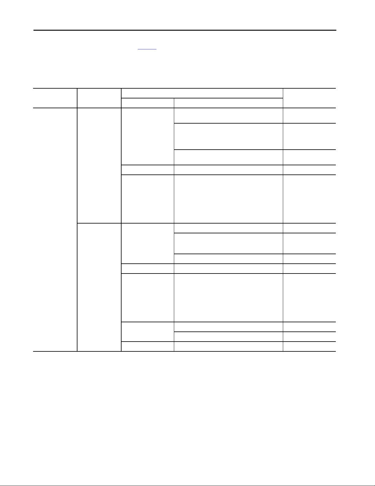
Table 3 describes the module compatibility requirements when you use
Compact 5000 I/O digital modules with Logix 5000 controllers.
Table 3 - Compact 5000 I/O Digital Modules Controller and Software Compatibility Requirements
Digital Module Operation in a Control System Chapter 1
Modules Location
Standard Modules
5069-IA16, 5069-IB16,
5069-IB16F, 5069IB16K, 5069-IB6F-3W,
5069-OA16, 5069-OB8,
5069-OB16, 5069OB16F, 5069-OB16K,
5069-OW4I, 5069OW16, 5069-OX4I
Local I/O modules CompactLogix 5380 5069-L320ER, 5069-L320ERMK, 5069-L330ERMK,
Remote I/O modules CompactLogix 5380 5069-L320ER, 5069-L340ERM Version 28.00.00 or later
Controllers
5069-L340ERM, 5069-L350ERMK
5069-L306ER, 5069-L306ERM, 5069-L310ER, 5069-L310ERM,
5069-L310ER-NSE, 5069-L310ERS2, 5069-L320ERM,
5069-L320ERMK, 5069-L330ER, 5069-L330ERM,
5069-L330ERMK, 5069-L340ER
5069-L350ERM, 5069-L350ERMK, 5069-L380ERM,
5069-L3100ERM
CompactLogix 5480 5069-L46ERMW Version 32.00.00 or later
Compact GuardLogix 5380 5069-L306ERS2, 5069-L306ERMS2, 5069-L310ERS2, 5069-
L310ERMS2, 5069-L320ERS2, 5069-L320ERS2K, 5069L320ERMS2, 5069-L320ERMS2K, 5069-L330ERS2, 50695069-L330ERS2K, L330ERMS2, 5069-L330ERMS2K, 5069L340ERS2, 5069-L340ERMS2, 5069-L350ERS2, 5069L350ERS2K, 5069-L350ERMS2, 5069-L350ERMS2K, 5069L380ERS2, 5069-L380ERMS2, 5069-L3100ERS2, 5069L3100ERMS2
5069-L306ER, 5069-L306ERM, 5069-L310ER, 5069-L310ERM,
5069-L310ER-NSE, 5069-L310ERS2, 5069-L320ERM, 5069L330ER, 5069-L330ERM, 5069-L340ER
5069-L350ERM, 5069-L380ERM, 5069-L3100ERM Version 30.00.00 or later
CompactLogix 5480 5069-L46ERMW Version 32.00.00 or later
Compact GuardLogix 5380 5069-L306ERS2, 5069-L306ERMS2, 5069-L310ERS2, 5069-
L310ERMS2, 5069-L320ERS2, 5069-L320ERS2K, 5069L320ERMS2, 5069-L320ERMS2K, 5069-L330ERS2, 50695069-L330ERS2K, L330ERMS2, 5069-L330ERMS2K, 5069L340ERS2, 5069-L340ERMS2, 5069-L350ERS2, 5069L350ERS2K, 5069-L350ERMS2, 5069-L350ERMS2K, 5069L380ERS2, 5069-L380ERMS2, 5069-L3100ERS2, 5069L3100ERMS2
ControlLogix® 5580 1756-L83E, 1756-L85E Version 28.00.00 or later
1756-L81E, 1756-L82E, 1756-L84E Version 29.00.00 or later
GuardLogix 5580 1756-L81ES, 1756-L82ES, 1756-L83ES, 1756-L84ES Version 31.00.00 or later
Logix Designer
ApplicationSystem Cat. Nos.
Version 28.00.00 or later
Version 29.00.00 or later
Version 30.00.00 or later
Version 31.00.00 or later
Version 29.00.00 or later
Version 31.00.00 or later
Rockwell Automation Publication 5069-UM004A-EN-P - April 2019 19
Page 20

Chapter 1 Digital Module Operation in a Control System
Table 3 - Compact 5000 I/O Digital Modules Controller and Software Compatibility Requirements
Modules Location
Safety Modules
5069-IB8S,
5069-IB8SK,
5069-OBV8S,
5069-OBV8SK
Local Compact GuardLogix 5380 5069-L306ERS2, 5069-L306ERMS2, 5069-L310ERS2, 5069-
Remote Compact GuardLogix 5380 5069-L306ERS2, 5069-L306ERMS2, 5069-L310ERS2, 5069-
Controllers
L310ERMS2, 5069-L320ERS2, 5069-L320ERS2K, 5069L320ERMS2, 5069-L320ERMS2K, 5069-L330ERS2, 50695069-L330ERS2K, L330ERMS2, 5069-L330ERMS2K, 5069L340ERS2, 5069-L340ERMS2, 5069-L350ERS2, 5069L350ERS2K, 5069-L350ERMS2, 5069-L350ERMS2K, 5069L380ERS2, 5069-L380ERMS2, 5069-L3100ERS2, 5069L3100ERMS2
L310ERMS2, 5069-L320ERS2, 5069-L320ERS2K, 5069L320ERMS2, 5069-L320ERMS2K, 5069-L330ERS2, 50695069-L330ERS2K, L330ERMS2, 5069-L330ERMS2K, 5069L340ERS2, 5069-L340ERMS2, 5069-L350ERS2, 5069L350ERS2K, 5069-L350ERMS2, 5069-L350ERMS2K, 5069L380ERS2, 5069-L380ERMS2, 5069-L3100ERS2, 5069L3100ERMS2
GuardLogix 5580 1756-L81ES, 1756-L82ES, 1756-L83ES, 1756-L84ES
Logix Designer
ApplicationSystem Cat. Nos.
Version 32.00.00 or later
20 Rockwell Automation Publication 5069-UM004A-EN-P - April 2019
Page 21

Digital Module Operation in a Control System Chapter 1
Types of Modules
Standard Modules
DC INPUT
DC INPUT
5069-IB16
5069-IB16
SA Power MOD Power
CONTROLLER
DC INPUT
5069-IB16
5069-L46ERMW
UPS
R
R
OK
FAN 1
B
B
RUN
SD
F
F
FORCE
FAN 2
NET B1
B1
LINK B1
NET A1
LINK A1
NET A2
A1
LINK A2
1
2
CompactLogix 5480
A2
Compact GuardLogix
MP
SA
SPEED X1
LINK X1
™
Safety Modules
SIL2 CPU
5069-L3100ERMS2
SA Power MOD Power
5069-IB8S5069-IB8S
DC OUTPUT
5069-OB16
DC INPUT
5069-IB16
5069-OBV8S
ANALOG INPUT
5069-IY4
DC OUTPUT
5069-OB16
OUTPUT OUTPUT
Table 4 describes the Compact 5000 I/O digital modules.
Table 4 - Compact 5000 I/O Digital Modules
ANALOG OUTPUT
5069-OF8
ANALOG INPUT
ANALOG OUTPUT
5069-IY4
5069-OF8
5069-OBV8S
Module Type Cat. No. Description
Standard 5069-IA16 79…264V AC 16-point, input module
5069-IB16 10…32V DC 16-point, sinking input module
5069-IB16K 10…32V DC 16-point, conformal coated sinking input module
5069-IB16F 10…32V DC 16-point, sinking fast input module
5069-IB6F-3W 10…32V DC 6-point, 3-wire, sinking fast input module
5069-OA16 85…264V AC 16-point, output module
5069-OB8 10…32V DC 8-point, sourcing high-current output module
5069-OB16 10…32V DC 16-point, sourcing output module
5069-OB16K 10…32V DC 16-point, conformal coated sourcing output
module
5069-OB16F 10…32V DC 16-point, sourcing fast output module
5069-OW4I 5…264V AC /125V DC 4-point, isolated normally open relay
output module
5069-OW16 5…264V AC/125V DC 16-point, normally open relay output
module
5069-OX4I 5…264V AC /125V DC 4-point, isolated normally open/
normally closed relay output module
Safety
(1)
5069-IB8S 18…32V DC 8-point, safety sinking input module
5069-IB8SK 18…32V DC 8-point, conformal coated safety sinking
input module
5069-OBV8S 18…32V DC 8-point, safety output module that can be used as
follows:
• Bipolar output module
• Sourcing output module
5069-OBV8SK 18…32V DC 8-point, conformal coated safety output module
that can be used as follows:
• Bipolar output module
• Sourcing output module
(1) You can use the safety modules in applications that are rated up to, and including, SIL CL3, PLe, Cat. 4 as defined in IEC 61508, IEC
61511, IEC 62061, and ISO 13849-1.
Rockwell Automation Publication 5069-UM004A-EN-P - April 2019 21
Page 22
Chapter 1 Digital Module Operation in a Control System
Module Overview
Standard Modules
DC INPUT
DC INPUT
5069-IB16
5069-IB16
SA Power MOD Power
CONTROLLER
DC INPUT
DC INPUT
5069-IB16
5069-IB16
5069-L46ERMW
UPS
R
R
OK
FAN 1
B
B
RUN
SD
F
F
FORCE
FAN 2
NET B1
B1
LINK B1
NET A1
LINK A1
NET A2
A1
LINK A2
1
2
CompactLogix 5480
A2
MP
SA
SPEED X1
LINK X1
™
Safety Modules
SIL2 CPU
5069-L3100ERMS2
5069-IB8S5069-IB8S
DC OUTPUT
5069-OB16
DC OUTPUT
5069-OB16
OUTPUT OUTPUT
5069-OBV8S
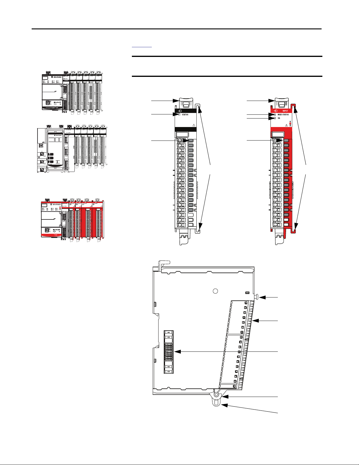
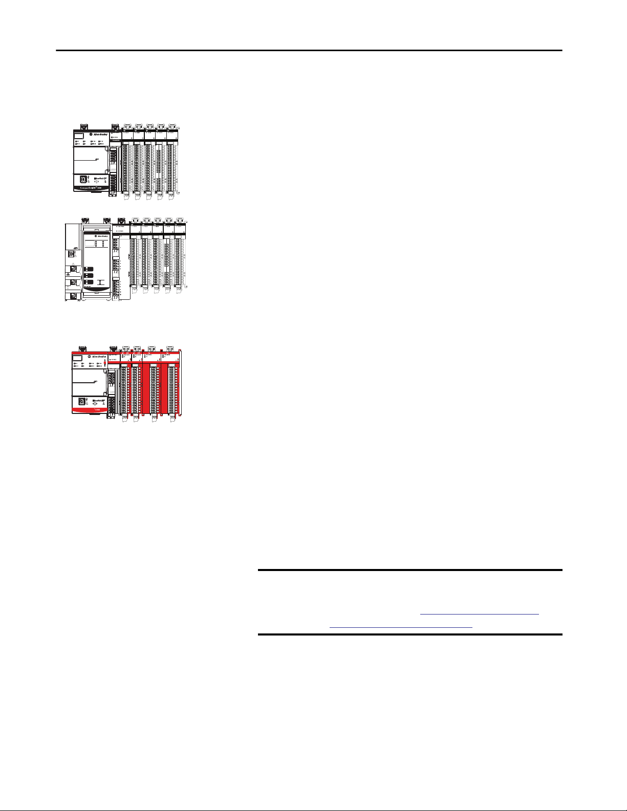
Figure 1 shows the parts of a Compact 5000 I/O digital module.
IMPORTANT Compact 5000 I/O safety modules look the same from the front with the
ANALOG INPUT
ANALOG OUTPUT
5069-IY4
5069-OF8
exception that the safety modules have a red
Figure 1 - Example Compact 5000 I/O Digital Modules
1
2
ANALOG INPUT
ANALOG OUTPUT
5069-IY4
5069-OF8
DC INPUT
5069-IB16
3
4
5069-OBV8S
1
2
3
housing.
5069-IB8S
4
Compact GuardLogix
SA Power MOD Power
5
6
7
8
22 Rockwell Automation Publication 5069-UM004A-EN-P - April 2019
9
Page 23
Digital Module Operation in a Control System Chapter 1
Table 5 - Compact 5000 I/O Digital Module Parts
Item Item Description
1 DIN rail latch Locks the module on the DIN rail.
2 Module and
power status
indicators
3 I/O status
indicators
4 Interlocking
pieces
5 RTB handle Anchors the RTB on the module.
6 RTB Provides a wiring interface for the module.
7 MOD Power bus
and SA Power
bus connectors
8 RTB lower tab Hooks RTB onto the module to begin installation.
9 Lower hook Used with cable tie after you wire the module.
Standard modules:
• STATUS - Displays the status of communication and module health.
Safety modules:
• MOD Status - Displays the status of communication and module health.
• SA - Displays whether SA power is applied to the module.
Displays the status of the input/output point.
Securely installs Compact 5000 I/O digital modules in the system.
Pass system-side and field-side power across the internal circuitry of the
module in a Compact 5000 I/O system. The connectors are isolated from
each other.
Rockwell Automation Publication 5069-UM004A-EN-P - April 2019 23
Page 24
Chapter 1 Digital Module Operation in a Control System
Local I/O Modules or Remote I/O Modules
CompactLogix 5380 Controller Local Compact 5000
I/O Standard Modules
DC INPUT
DC INPUT
5069-IB16
5069-IB16
DC OUTPUT
5069-OB16
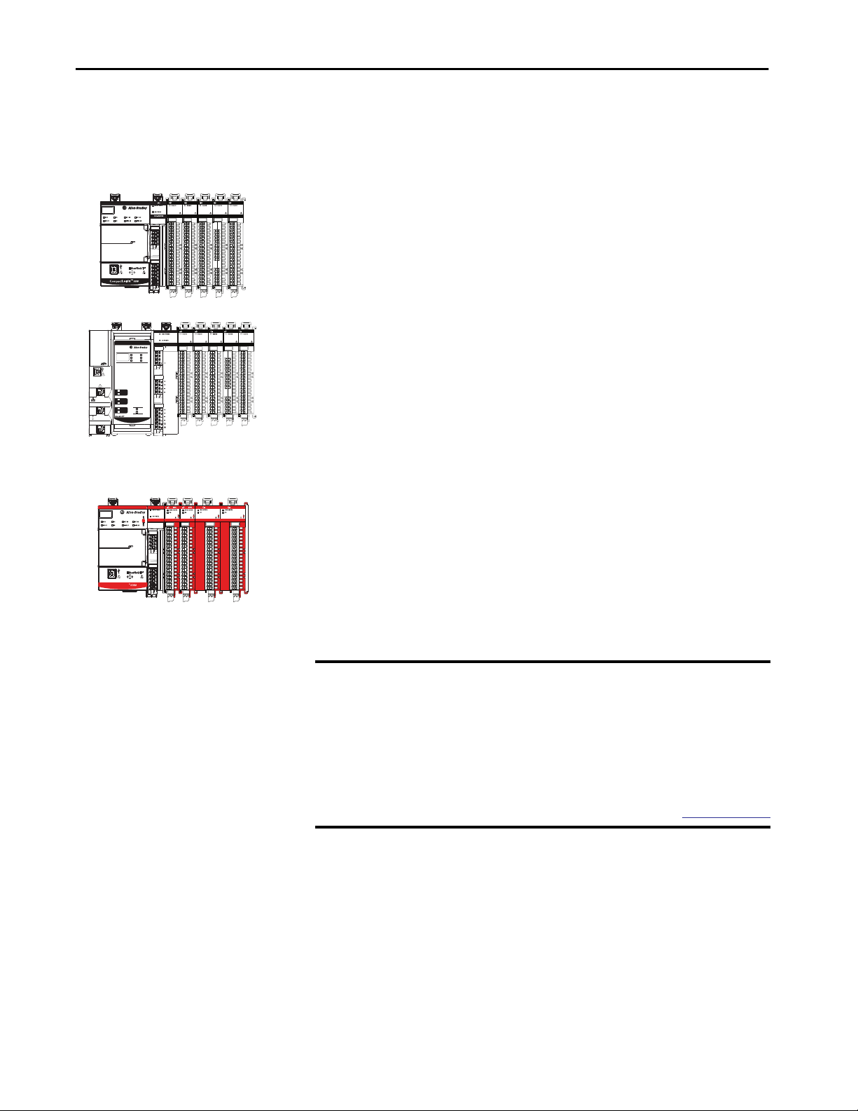
You can use Compact 5000 I/O digital modules as local or remote
I/O modules, with some restrictions that are based on the module and
controller type. Compatibility requirements apply and are described in
Controller and Software Compatibility on page 18.
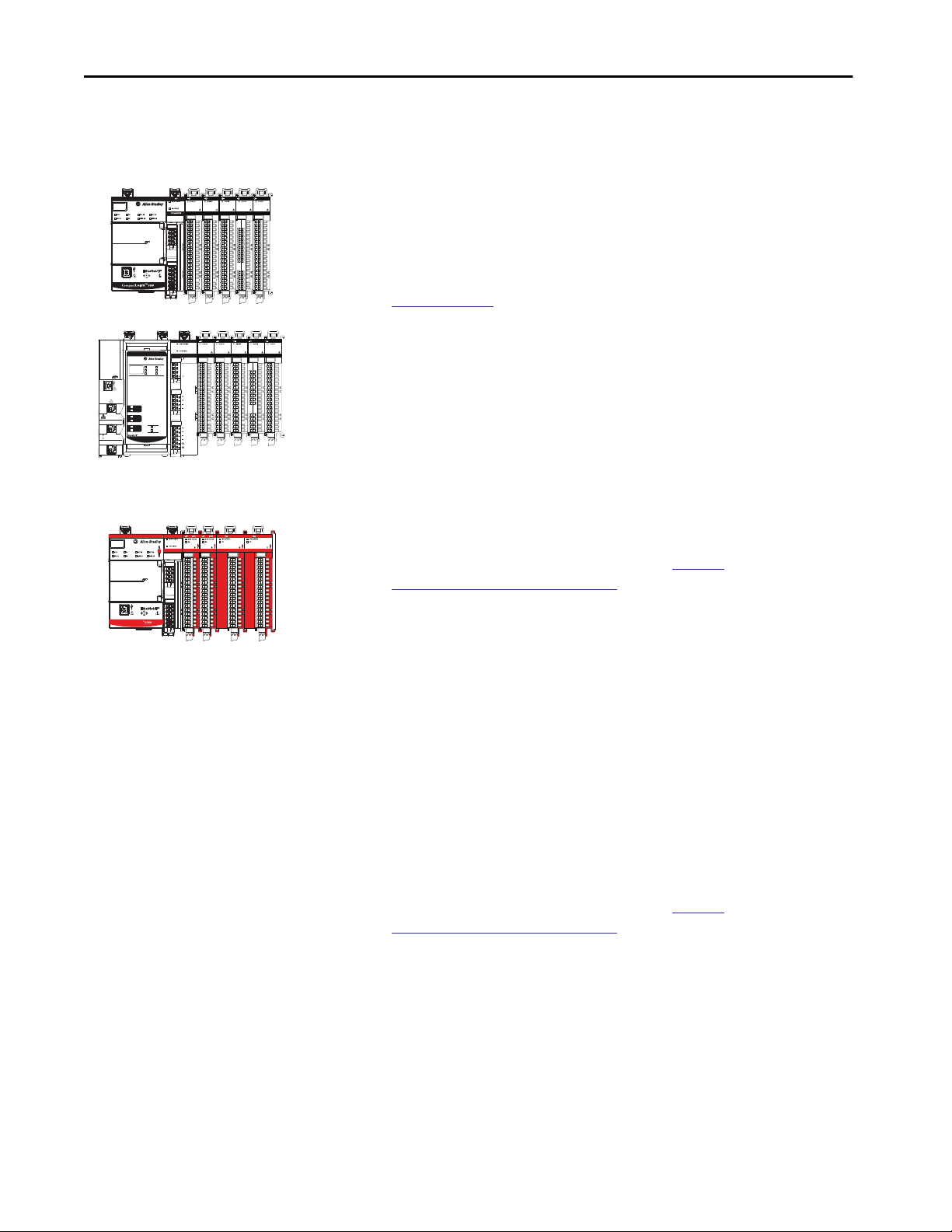
Local I/O Modules
When Compact 5000 I/O digital modules reside in the same system as the
controller, the modules are local I/O modules.
Local I/O modules are installed to the right of the controller and exchange
data with the controller over the system backplane.
Figure 2 - Local Compact 5000 I/O Digital Modules
ANALOG INPUT
5069-IY4
ANALOG OUTPUT
5069-OF8
CompactLogix 5480 Controller Local Compact 5000 I/O
CONTROLLER
5069-IB16
5069-L46ERMW
UPS
R
OK
FAN 1
RUN
SD
FORCE
FAN 2
R
B
B
F
F
DC INPUT
Standard Modules
DC OUTPUT
DC INPUT
5069-IB16
5069-OB16
ANALOG INPUT
5069-IY4
ANALOG OUTPUT
5069-OF8
MP
B1
SA Power MOD Power
A1
1
2
NET B1
LINK B1
NET A1
LINK A1
NET A2
LINK A2
CompactLogix 5480
SPEED X1
LINK X1
™
SA
A2
Compact GuardLogix 5380 Controller Local Compact 5000 I/O
Digital Modules
OUTPUT
Compact GuardLogix
SIL2 CPU
5069-L3100ERMS2
DC INPUT
5069-IB16
5069-OBV8S
5069-IB8S
SA Power MOD Power
ANALOG OUTPUT
5069-OF8
COUNTER
5069-HSC2xOB4
24 Rockwell Automation Publication 5069-UM004A-EN-P - April 2019
Page 25
Digital Module Operation in a Control System Chapter 1
Remote I/O Modules
When Compact 5000 I/O digital modules reside in a separate location from
Logix 5000 controllers, they are remote I/O modules. Remote Compact 5000
I/O digital modules are accessible over an EtherNet/IP™ network via a
Compact 5000 I/O EtherNet/IP adapter.
The modules are installed to the right of the adapter and exchange data across
the remote system backplane. The data is then exchanged with the controller
over the EtherNet/IP network.
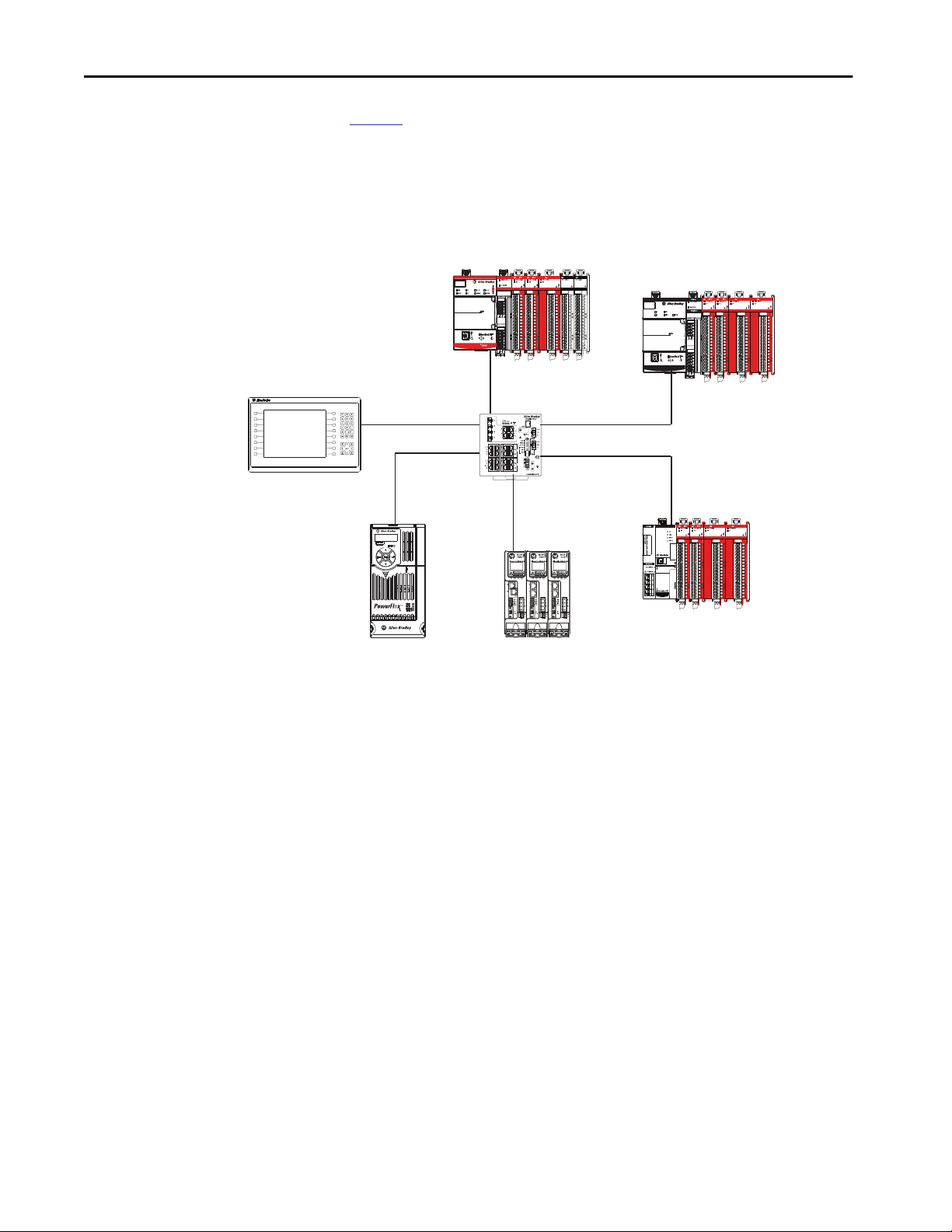
IMPORTANT Remember, some restrictions apply when you use the I/O modules remotely.
For example, you can use Compact 5000 I/O safety modules as remote I/O
modules only in Compact GuardLogix 5380 or GuardLogix 5380 control
systems.
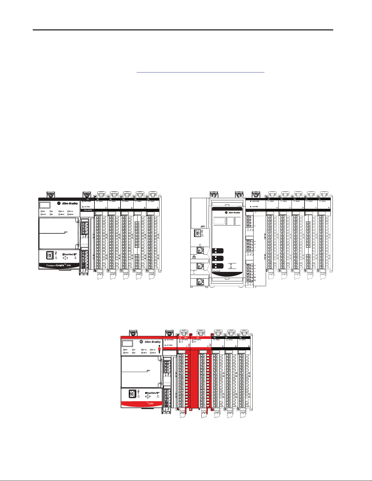
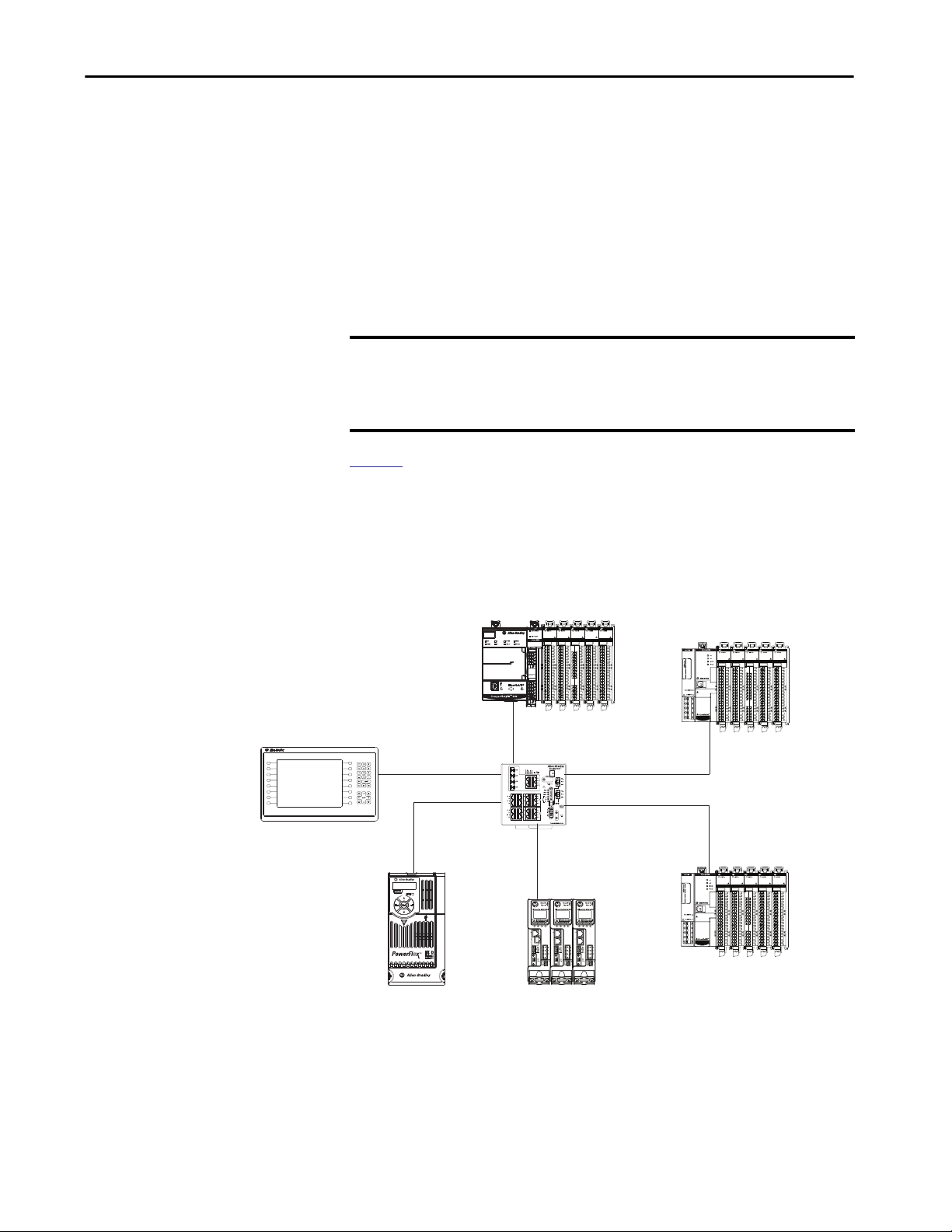
Figure 3 shows remote Compact 5000 I/O standard modules in an example
CompactLogix 5380 control system.
Figure 3 - Remote Compact 5000 I/O Standard Modules in a CompactLogix 5380
Control Applications
F1
F2
F3
F4
F5
F6
F7
F8
PanelView™ Plus 7 Terminal
F9
F10
F11
F12
F13
F14
F15
F16
PowerFlex® 527 Drive Kinetix® 5500 Drive
CompactLogix 5380 Controller
Compact 5000 I/O Standard Modules
Compact 5000 I/O EtherNet/IP Adapter
DC OUTPUT
DC INPUT
5069-IB16
SA Power MOD Power
COUNTER
ANALOG INPUT
ANALOG OUTPUT
5069-HSC2xOB4
5069-IY4
5069-OF8
5069-OB16
Compact 5000 I/O Standard Modules
DC OUTPUT
DC INPUT
5069-IB16
1
2
Compact 5000™ I/O
Compact 5000™ I/O
COUNTER
ANALOG INPUT
ANALOG OUTPUT
5069-HSC2xOB4
5069-IY4
5069-OF8
5069-OB16
Stratix® 5400 Switch
DC OUTPUT
DC INPUT
5069-IB16
1
2
Compact 5000™ I/O
Compact 5000™ I/O
527
COUNTER
ANALOG INPUT
ANALOG OUTPUT
5069-HSC2xOB4
5069-IY4
5069-OF8
5069-OB16
Compact 5000 I/O EtherNet/IP Adapter
Compact 5000 I/O Standard Modules
Rockwell Automation Publication 5069-UM004A-EN-P - April 2019 25
Page 26
Chapter 1 Digital Module Operation in a Control System
Figure 4 shows remote Compact 5000 I/O safety modules in a
Compact GuardLogix 5380 control application.
Figure 4 - Remote Compact 5000 I/O Safety Modules in a Compact GuardLogix 5380
Control Application
Compact GuardLogix 5380 Controller
Compact 5000 I/O Digital Modules
OUTPUT
SIL2 CPU
5069-L3100ERMS2
5069-IB8S 5069-IB8S
ANALOG OUTPUT
5069-HSC2xOB4
5069-OF8
5069-OBV8S
COUNTER
Compact 5000 I/O EtherNet/IP Adapter
Compact 5000 I/O Safety Modules
OUTPUT OUTPUT
5069-OBV8S
5069-IB8S 5069-IB8S
5069-OBV8S
F1
F2
F3
F4
F5
F6
F7
F8
F9
F10
F11
F12
F13
F14
F15
F16
PanelView Plus 7 Terminal
Compact GuardLogix
SA Power MOD Power
Stratix 5400 Switch
527
PowerFlex 527 Drive Kinetix 5500 Drive
SA Power MOD Power
Compact 5000™ I/O
OUTPUT OUTPUT
5069-OBV8S
5069-IB8S 5069-IB8S
Compact 5000™ I/O
5069-OBV8S
Compact 5000 I/O EtherNet/IP Adapter
Compact 5000 I/O Safety Modules
26 Rockwell Automation Publication 5069-UM004A-EN-P - April 2019
Page 27
F1
F2
F3
F4
F5
F6
F7
F8
F9
F10
F11
F12
F13
F14
F15
F16
PanelView Plus 7 Terminal
Digital Module Operation in a Control System Chapter 1
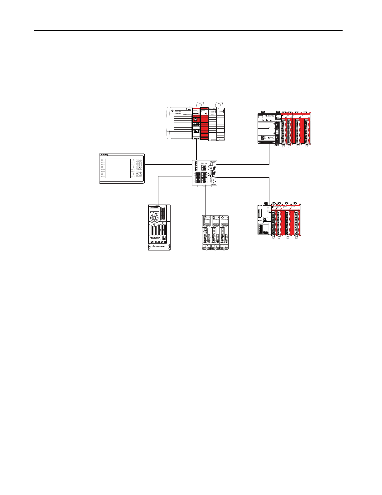
Figure 5 shows remote Compact 5000 I/O safety modules in a
GuardLogix 5580 control application.
Figure 5 - Remote Compact 5000 I/O Safety Modules in a GuardLogix 5580 Control Application
GuardLogix 5580 Safety Controller
GuardLogix 1756-L8SP Safety Partner
Logix5584ES™
NET
LINK
FORCESD OK
RUN
REM
PROG
RUN
DC INPUT
Logix55L8SP™
OK
Stratix 5400 Switch
Compact 5000 I/O EtherNet/IP Adapter
Compact 5000 I/O Safety Modules
OUTPUT OUTPUT
5069-OBV8S
OUTPUT OUTPUT
5069-OBV8S
5069-OBV8S
5069-OBV8S
Compact 5000™ I/O
5069-IB8S 5069-IB8S
SA Power MOD Power
5069-IB8S 5069-IB8S
527
PowerFlex 527 Drive Kinetix 5500 Drive
Compact 5000™ I/O
Compact 5000 I/O EtherNet/IP Adapter
Compact 5000 I/O Safety Modules
Rockwell Automation Publication 5069-UM004A-EN-P - April 2019 27
Page 28
Chapter 1 Digital Module Operation in a Control System
Secure Access to the System
Standard Modules
DC OUTPUT
DC INPUT
5069-IB16
SA Power MOD Power
CONTROLLER
5069-L46ERMW
UPS
R
R
OK
FAN 1
B
B
RUN
SD
F
F
FORCE
FAN 2
NET B1
B1
LINK B1
NET A1
LINK A1
NET A2
A1
LINK A2
1
2
CompactLogix 5480
A2
MP
SA
SPEED X1
LINK X1
™
Safety Modules
SIL2 CPU
5069-L3100ERMS2
ANALOG INPUT
DC INPUT
5069-IB16
DC INPUT
5069-IB16
5069-IB8S5069-IB8S
5069-OB16
DC INPUT
5069-IB16
5069-OBV8S
5069-IY4
DC OUTPUT
5069-OB16
OUTPUT OUTPUT
ANALOG OUTPUT
5069-OF8
ANALOG INPUT
ANALOG OUTPUT
5069-IY4
5069-OF8
5069-OBV8S
To secure access to a Logix 5000 controller, Compact 5000 EtherNet/IP
adapter, or I/O module by authorized users only, consider the
following options:
• Password protect the source and execution of the control program.
• Deploy EtherNet/IP devices in accordance with recommended
architectures and concepts. See the Converged Plantwide Ethernet
(CPwE) Design and Implementation Guide, publication
ENET-TD001.
• Implement physical barriers, such as locked cabinets.
To secure access to the system, consider the following options:
• Follow industry best practices to harden your PCs and servers, including
anti-virus/anti-malware and application whitelisting solutions.
The recommendations are published at the Rockwell Automation®
technical support center in Knowledgebase article Rockwell
Automation Customer Hardening Guidelines, #546987.
The technical support center is available at:
https://
rockwellautomation.custhelp.com/
Compact GuardLogix
SA Power MOD Power
• Develop and deploy backup and disaster recovery policies and
procedures. Test backups on a regular schedule.
• Minimize network exposure for all control system devices and systems,
and make sure that they are not accessible from the Internet.
• Locate control system networks and devices behind firewalls and isolate
them from the business network.
• Subscribe to Knowledgebase article Industrial Security Advisory Index,
#54102 at the Rockwell Automation technical support center so you
have access to information about security matters that affect Rockwell
Automation products.
The technical support center is available at:
https://
rockwellautomation.custhelp.com/
28 Rockwell Automation Publication 5069-UM004A-EN-P - April 2019
Page 29
Digital Module Operation in a Control System Chapter 1
Ownership
Standard Modules
OK
FAN 1
RUN
SD
FORCE
FAN 2
NET B1
B1
LINK B1
NET A1
LINK A1
NET A2
Compact GuardLogix
SPEED X1
LINK A2
LINK X1
™
CompactLogix 5480
Safety Modules
A1
1
2
A2
Every I/O module in a Logix 5000 control system must be owned by a
controller, also known as the owner-controller. When a Compact 5000 I/O
digital module is used in a Logix 5000 control system, the owner-controller
performs the following:
DC OUTPUT
DC INPUT
5069-IB16
ANALOG INPUT
DC INPUT
5069-IB16
ANALOG OUTPUT
5069-IY4
5069-OF8
5069-OB16
• Stores configuration data for every module that it owns.
• Can reside in a location that differs from the Compact 5000 I/O
SA Power MOD Power
digital modules.
• Sends the I/O module configuration data to define module behavior
CONTROLLER
5069-L46ERMW
UPS
R
R
B
B
F
F
MP
DC OUTPUT
DC INPUT
5069-IB16
ANALOG INPUT
DC INPUT
5069-IB16
ANALOG OUTPUT
5069-IY4
5069-OF8
5069-OB16
and begin operation in the control system.
Each Compact 5000 I/O digital module must continuously maintain
communication with its owner-controller during normal operation.
SA
Typically, each I/O module in a system has only one owner-controller. Output
modules are limited to one owner-controller.
SIL2 CPU
5069-L3100ERMS2
OUTPUT OUTPUT
5069-OBV8S
5069-IB8S5069-IB8S
5069-OBV8S
Multiple Owners of Compact 5000 I/O Digital Input Modules
Typically only one owner-controller is connected to a Compact 5000 I/O
digital input module. However, multiple Logix 5000 controllers can connect to
SA Power MOD Power
Compact 5000 I/O digital input modules as owner-controllers.
In this case, the following conditions must exist:
• The controllers maintain the same configuration.
• The configuration in each controller uses a Data connection to the
input module.
• The first controller to make a connection to the input module is the
only controller that can change the connection. Therefore, it is ‘owns’
the module configuration.
IMPORTANT If the controller that owns the module configuration changes the
configuration, the other controllers are not notified of the changes.
For more information, see
Configuration Changes in an Input
Module with Multiple Owners on page 30.
Rockwell Automation Publication 5069-UM004A-EN-P - April 2019 29
Page 30
Chapter 1 Digital Module Operation in a Control System
• The controllers that do maintain, but do not ‘own’, the module
configuration are similar to Listen-only controllers.
The difference between the controllers is that the controllers that
maintain, but do not own, the module configuration can use a Multicast
or Unicast connection over the EtherNet/IP network.
Configuration Changes in an Input Module with Multiple Owners
DC OUTPUT
DC INPUT
5069-IB16
5069-OB16
SA Power MOD Power
ANALOG INPUT
5069-IY4
ANALOG OUTPUT
5069-OF8
COUNTER
5069-HSC2xOB4
For more information on Listen-only controllers, see
Listen Only on
page 56.
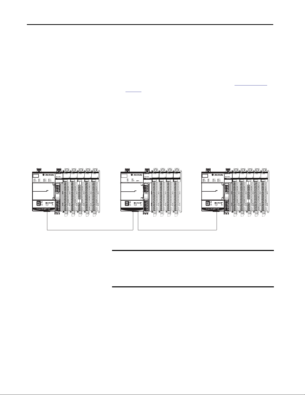
You must be careful when changing the configuration data of an input module
in a multiple-owner scenario. If the configuration data is changed in owner A
and sent to the module, the changed configuration data is accepted as the new
configuration for the module. Owner B continues to listen unaware that any
changes have been made in the behavior of the input module, as illustrated.
Figure 6 - Module Configuration Changes with Multiple Owners
DC OUTPUT
DC OUTPUT
DC INPUT
Compact 5000™ I/O
DC INPUT
5069-IB16
5069-IB16
5069-OB16
5069-OB16
SA Power MOD Power
DC OUTPUT
DC INPUT
5069-IB16
5069-OB16
SA Power MOD Power
COUNTER
ANALOG INPUT
ANALOG OUTPUT
5069-HSC2xOB4
5069-IY4
5069-OF8
Controller A sends new configuration to the module. Controller B is unaware of any configuration changes.
IMPORTANT A message in Logix Designer application alerts you to the possibility of a
multiple owner-controller situation and lets you inhibit the connection
before changing the module configuration. When changing the
configuration for a module with multiple owners, we recommend that you
inhibit the connection.
30 Rockwell Automation Publication 5069-UM004A-EN-P - April 2019
Page 31

Digital Module Operation in a Control System Chapter 1
To help prevent other owner-controllers from receiving potentially erroneous
data, use the following steps when changing the configuration of a module in a
multiple owner scenario while online.
1. For each owner-controller, inhibit the connection to the module either
in the software on the Connection tab or the message dialog box
warning you of the multiple owner condition.
2. Make the appropriate configuration data changes in the software.
For more information on how to use the Logix Designer application to
change the configuration, see the following:
– Standard modules - Chapter 6,
Configure a Standard Module on
page 149
– Safety modules - Chapter 7,
Configure and Replace Safety Modules
on page 191
Construct a System
Standard Modules
DC OUTPUT
DC INPUT
DC INPUT
5069-IB16
5069-IB16
5069-OB16
SA Power MOD Power
CONTROLLER
DC INPUT
DC INPUT
5069-IB16
5069-IB16
5069-L46ERMW
UPS
R
R
OK
FAN 1
B
B
RUN
SD
F
F
FORCE
FAN 2
NET B1
B1
LINK B1
NET A1
LINK A1
NET A2
A1
LINK A2
1
2
CompactLogix 5480
A2
MP
SA
SPEED X1
LINK X1
™
3. Repeat
step 1 and step 2 for all owner-controllers, to make the exact
same changes in each.
4. Clear the Inhibit checkbox in each owner-controller configuration.
Before you use your Compact 5000 I/O digital modules, you must complete
tasks that are based on the way that you use the modules. That is, if the
modules are used locally, remotely or both locally and remotely.
ANALOG INPUT
ANALOG OUTPUT
5069-IY4
5069-OF8
Local I/O Modules
Complete the following:
1. Install a CompactLogix 5380, CompactLogix 5480, or
DC OUTPUT
ANALOG INPUT
ANALOG OUTPUT
5069-IY4
5069-OF8
5069-OB16
Compact GuardLogix 5380 controller.
IMPORTANT Remember, you must use a Compact GuardLogix 5380 controller if
the local Compact 5000 I/O digital modules includes safety
modules.
For more information on controller compatibility, see
Controller and
Software Compatibility on page 18.
Compact GuardLogix
Safety Modules
SIL2 CPU
5069-L3100ERMS2
5069-IB8S5069-IB8S
SA Power MOD Power
OUTPUT OUTPUT
5069-OBV8S
2. Install the modules to the right of the controller.
5069-OBV8S
3. Install the end cap on the last module in the local system.
IMPORTANT The end cap in a CompactLogix 5380, CompactLogix 5480, or
Compact GuardLogix 5380 control system covers the exposed
interconnection on the last module on the DIN rail.
If you do not install an end cap on the last module on the DIN rail,
equipment damage or injury can occur.
Rockwell Automation Publication 5069-UM004A-EN-P - April 2019 31
Page 32

Chapter 1 Digital Module Operation in a Control System
Remote I/O Modules
Complete the following:
1. Install a controller that is compatible with the remote Compact 5000
I/O digital modules to be used in the application via an EtherNet/IP
network.
IMPORTANT Remember, you must use a Compact GuardLogix 5380 controller or
GuardLogix 5580 controller if the set of remote Compact 5000 I/O
digital modules include safety modules.
For more information on controller compatibility, see
Software Compatibility on page 18.
2. Install an EtherNet/IP network.
3. Connect the controller to the network.
4. Install a Compact 5000 I/O EtherNet/IP adapter.
Controller and
5. Connect the adapter to the network.
6. Install the Compact 5000 I/O digital modules to the right of the
adapter.
7. Install the end cap on the last module in the local system.
IMPORTANT The end cap in a CompactLogix 5380, CompactLogix 5480, or
Compact GuardLogix 5380 control system covers the exposed
interconnection on the last module on the DIN rail.
If you do not install an end cap on the last module on the DIN rail,
equipment damage or injury can occur.
For information on how to install compatible controllers, adapters, and
Compact 5000 I/O modules, see the publications that are listed in
Table 2 on
page 14.
32 Rockwell Automation Publication 5069-UM004A-EN-P - April 2019
Page 33

Digital Module Operation in a Control System Chapter 1
Use a 5069-ARM Address Reserve Module to Reserve a Node Address
Every Compact 5000 I/O digital module has a unique node address in a
system. As modules are installed, the node addresses increment. The Logix
Designer application project includes modules in the I/O Configuration that
correspond to the physical modules.
If a module is not available during initial system installation and operation, you
can use a 5069-ARM address reserve module to reserve the slot in the system.
That is, you install the 5069-ARM address reserve module to reserve the node
address. The address reserve module remains installed until the I/O module is
available.
When you install the address reserve module, you also make sure the
subsequently-installed modules are located at the correct node address.
You use the corresponding entry in the Logix Designer application project to
reserve the node address. That is, when you add modules to the I/O
Configuration tree in the project, you add an address reserve module at the
node address that matches the physical module location.
Figure 7 - CompactLogix 5380 Control System with a 5069-ARM Address Reserve Module
5069-ARM Address Reserve Module
ANALOG OUTPUT
5069-OF8
SERIAL
5069-SERIAL
CH0 TXD
CH0 RXD
CH1 TXD
CH1 RXD
5069-IB16F
DC INPUT
ADDRESS RESERVE
5069-ARM
ANALOG INPUT
5069-IY4
DC INPUT
DC INPUT
5069-IB16
5069-IB16
SA Power MOD Power
When the I/O becomes available, you complete the following tasks.
1. Remove the 5069-ARM module from the system.
2. Install the I/O module in the slot that previously contained the 5069ARM module.
3. Replace the 5069-ARM module entry in the I/O Configuration section
of the Logix Designer application project with the new I/O module.
For more information on how to use a 5069-ARM module in a Logix
Designer application project, see
Reserve an I/O Module Slot on
page 159.
Rockwell Automation Publication 5069-UM004A-EN-P - April 2019 33
Page 34

Chapter 1 Digital Module Operation in a Control System
Power the Modules
Standard Modules
DC OUTPUT
DC INPUT
DC INPUT
5069-IB16
5069-IB16
5069-OB16
SA Power MOD Power
CONTROLLER
DC INPUT
DC INPUT
5069-IB16
5069-IB16
5069-L46ERMW
UPS
R
R
OK
FAN 1
B
B
RUN
SD
F
F
FORCE
FAN 2
NET B1
B1
LINK B1
NET A1
LINK A1
NET A2
A1
LINK A2
1
2
CompactLogix 5480
A2
MP
SA
SPEED X1
LINK X1
™
Safety Modules
SIL2 CPU
5069-L3100ERMS2
5069-OB16
OUTPUT OUTPUT
5069-OBV8S
5069-IB8S5069-IB8S
Compact 5000 I/O digital modules receive the following power types from
first component in the system, that is, the controller or adapter:
• System-side Power - Powers the system and lets modules transfer data
ANALOG INPUT
ANALOG OUTPUT
5069-IY4
5069-OF8
and execute logic.
System-side power is provided through the Module (MOD) Power
connector and is passed to each module as it is added to the system.
System-side power is also known as MOD power.
DC OUTPUT
ANALOG INPUT
ANALOG OUTPUT
5069-IY4
5069-OF8
• Field-side Power - Powers field-side devices that are connected to some
Compact 5000 I/O digital modules.
Field-side power is provided through the Sensor/Actuator (SA) Power
connector and is passed to each module as it is added to the system.
Field-side power is also known as SA power.
Power begins at the left-most device in the system and passes across the I/O
module internal circuitry via power buses. The MOD power bus and SA power
buses are isolated from each other. The left-most device is either a controller or
5069-OBV8S
an EtherNet/IP adapter.
Compact GuardLogix
IMPORTANT Remember the following:
SA Power MOD Power
• A system has only one MOD power bus.
• A system can have multiple SA Power buses. The first SA power bus
typically starts at the controller or adapter, and 5069-FPD field potential
distributors let you establish new SA power buses in the same system.
For more information, see the following:
–
Use a 5069-FPD Field Potential Distributor to Establish New SA Power
Buses on page 35.
– Rockwell Automation technical support center Knowledgebase
article, 5069 I/O Modules that Require Sensor/Actuator (SA) Power,
#751748.
The technical support center is available at: https://
rockwellautomation.custhelp.com/
• Compact GuardLogix 5380 controllers only:
– You must use an SELV/PELV-listed power supply to provide MOD
power and SA power to the controller.
– Additional requirements exist when you power a functional safety
application that includes Compact 5000 I/O safety modules.
For more information on these requirements, see
Power Requirements
When You Use Compact 5000 I/O Safety Modules on page 37.
34 Rockwell Automation Publication 5069-UM004A-EN-P - April 2019
Page 35

Digital Module Operation in a Control System Chapter 1
For more information on how to power local Compact 5000 I/O digital
modules, see the following:
– CompactLogix 5380 and Compact GuardLogix 5380 Controllers
User Manual, publication
– CompactLogix 5480 Controller User Manual, publication
5069-UM002
For more information on how to power remote Compact 5000 I/O digital
modules, see the Compact 5000 EtherNet/IP Adapters User Manual,
publication
5069-UM007.
5069-UM001
Use a 5069-FPD Field Potential Distributor to Establish New SA Power Buses
A 5069-FPD field potential distributor lets you change the field-side power
distribution source for Compact 5000 I/O modules to the right of the field
power distributor. The field potential distributor passes MOD power bus
signals through to the next module in the system.
You can use a 5069-FPD field potential distributor to establish a new SA power
bus in a system. The field potential distributor blocks the current that passes
across the SA power bus to the left of the field potential distributor. It then
establishes a new SA power bus for modules to the right.
The new SA power bus extends to the last module in the system or until
another field potential distributor establishes another SA power bus.
The SA power bus that a field potential distributor establishes functions in the
same way as the SA power bus that a controller or adapter establishes.
Rockwell Automation Publication 5069-UM004A-EN-P - April 2019 35
Page 36

Chapter 1 Digital Module Operation in a Control System
Figure 8 shows a CompactLogix 5380 system that includes a field potential
distributor. In this example, the field potential distributer is required to isolate
DC-type modules from AC-type modules.
Figure 8 - CompactLogix 5380 Controller System with 5069-FPD Field Potential Distributor
5069-FPD Field Potential Distributor
DC OUTPUT
DC INPUT
DC OUTPUT
5069-OB16
5069-OB16
FIELD POWER
5069-FPD
DC INPUT
5069-IB16
5069-IB16
SA Power Bus Providing DC Power SA Power Bus Providing AC Power
SA Power MOD Power
IMPORTANT You must install DC-type modules and AC-type modules on separate SA
Power buses.
You use 5069-FPD field potential distributors to establish SA Power
buses that are separate from the SA Power bus that the controller or
adapter establishes.
To install modules on separate SA Power buses, complete the
following steps.
1. Install the controller or adapter.
The controller or adapter establishes the first SA Power bus.
2. Install one type of modules to the right of the controller or adapter, for
example, DC-type modules.
3. Install a 5069-FPD field potential distributor.
The field potential distributor establishes a new SA Power bus that is
isolated from the first one.
4. Install the other type of modules to the right of the field potential
distributor, for example, AC-type modules.
Additional requirements apply when you use a 5069-FPD field potential
distributor in a local or remote system with Compact 5000 I/O
safety modules.
For more information on the additional requirements, see
Power
Requirements When You Use Compact 5000 I/O Safety Modules on page 37.
36 Rockwell Automation Publication 5069-UM004A-EN-P - April 2019
Page 37

Digital Module Operation in a Control System Chapter 1
Power Requirements When You Use Compact 5000 I/O Safety Modules
This section describes the requirements that apply when you connect MOD
power and SA power to a system that includes both types of Compact 5000
I/O digital modules.
There is some variation in the requirements based on whether the safety
modules are used as local or remote I/O modules. That is, if the modules are
installed in a Compact GuardLogix 5380 system or a Compact 5000 I/O
system accessible over an EtherNet/IP network.
Power a Compact GuardLogix 5380 System That Includes Compact 5000 I/O Safety Modules
Table 6 describes requirements that apply when you connect MOD power and
SA power to a Compact GuardLogix 5380 system with a mix of standard and
safety modules.
Table 6 - Connect Power to a Compact GuardLogix 5380 System with Compact 5000 I/O Standard and Safety Modules
Power
Type
MOD
Power
Requirements Example System
• You must use an SELV/PELV-listed
24V DC power supply to provide
MOD power to the controller.
SELV/PELV-listed
Power Supply
• The total continuous current draw
across the MOD power bus must
not be more than 5 A max at
18…24V DC.
We recommend that you calculate
the total MOD power bus current
draw as you install modules.
24V DC
Compact GuardLogix
+
-
SIL2 CPU
5069-L3100ERMS2
5069-IB8S
OUTPUT
5069-OBV8S
DC OUTPUT
DC INPUT
5069-IB16
5069-OB16
MOD Power
SA Power MOD Power
Rockwell Automation Publication 5069-UM004A-EN-P - April 2019 37
Page 38

Chapter 1 Digital Module Operation in a Control System
Table 6 - Connect Power to a Compact GuardLogix 5380 System with Compact 5000 I/O Standard and Safety Modules
Power
Requirements Example System
Type
SA Power • You must use an SELV/PELV-listed
power supply to provide SA power
to the controller.
• You must use a 24V DC power
supply to provide SA power to the
controller.
• The total continuous current draw
across an SA power bus must not
be more than 5 A max at
18…24V DC.
• You can install only Compact 5000
I/O safety modules and non-relay
DC-type standard modules next to
the safety controller.
IMPORTANT: This requirement is
related to the controller, not the
I/O modules.
However, you can install safety
modules and non-relay DC-type
modules to the right of a 5069FPD field potential distributor.
• If you install safety modules to the
right of a field potential
distributor, you must use an SELV/
PELV-listed power supply to
provide SA power.
• You must isolate the following
groups of modules on separate
SA Power buses:
– Safety and non-relay DC-type
standard modules
– Relay DC-type modules
– AC-type modules
• If you install AC-type modules, you
must install them to the right a
field potential distributor. The
120/240V AC power supply that
provides SA Power is not required
to be SELV/PELV-listed.
• If you install relay DC-type
standard modules, you must
install them to the right of a field
potential distributor. The 24V DC
power supply that provides SA
Power is not required to be
SELV/PELV-listed.
Compact GuardLogix
SELV/PELV-listed
Power Supply
OUTPUT
DC INPUT
5069-IB16
FIELD POWER
5069-FPD
Compact 5000 I/O
120/240V AC
standard modules
120/240V
AC
SA Power
+
SIL2 CPU
5069-L3100ERMS2
5069-IB8S
Compact 5000 I/O safety
modules and 24V DC
standard input modules
SA Power MOD Power
+
24V DC
-
5069-OBV8S
SA Power
Non SELV/PELV-listed Power Supply
The modules on this SA power bus are 120/240V AC modules.
This power supply can also be a non SELV/PELV-listed 24V DC
power supply, if necessary, based on system configuration.
The SA Power to adjacent SA Power electrical isolation that
the 5069-FPD field potential distributor provides has a rating
of 240V AC (continuous) reinforced insulation type.
FIELD POWER
5069-FPD
5069-IB8S
OUTPUT
5069-OBV8S
Compact 5000 I/O
safety modules
SA Power
+
-
24V DC
-
SELV/PELV-listed
Power Supply
38 Rockwell Automation Publication 5069-UM004A-EN-P - April 2019
Page 39

Power a Remote Compact 5000 I/O System That Includes Compact 5000 I/O Safety Modules
Table 7 describes requirements that apply when you connect MOD power and
SA power to a Compact 5000 I/O system with standard and safety modules.
Table 7 - Connect Power to a Compact 5000 I/O System with Standard and Safety Modules
Digital Module Operation in a Control System Chapter 1
Power
Requirements Example System
Type
MOD
Power
• You must use an SELV/PELV-listed
power supply to provide MOD
power to the controller.
• The total continuous current draw
across the MOD power bus must
not be more than 10 A max at
18…24V DC.
We recommend that you calculate
the total MOD power bus current
draw as you install modules.
SA Power • You must use an SELV/PELV-listed
power supply to provide SA power
to the adapter.
• You must use a 24V DC power
supply to provide SA power to the
adapter.
• The total continuous current draw
across an SA power bus must not
be more than 5 A max at
18…24V DC.
• If you install safety modules to the
right of a field potential
distributor, you must use an SELV/
PELV-listed power supply to
provide SA power.
• You must isolate the following
groups of modules on separate
SA Power buses:
– Safety and non-relay DC-type
standard modules
– Relay DC-type modules
– AC-type modules
• If you install AC-type modules, you
must install them to the right a
field potential distributor. The
120/240V AC power supply that
provides SA Power is not required
to be SELV/PELV-listed.
• If you install relay DC-type
standard modules, you must
install them to the right of a field
potential distributor. The 24V DC
power supply that provides SA
Power is not required to be
SELV/PELV-listed.
SELV/PELV-listed
Power Supply
Compact 5000™ I/O
24V DC
SELV/PELV-listed
Power Supply
+
24V DC
5069-OBV8S
5069-IB8S
Compact 5000 I/O safety
modules and 24V DC
standard input module
-
Compact 5000™ I/O
OUTPUT
DC INPUT
FIELD POWER
5069-FPD
5069-IB16
Compact 5000 I/O
120/240V AC
standard modules
SA Power SA Power
+
-
120/240V
AC
Non SELV/PELV-listed Power Supply
The modules on this SA power bus are 120/240V AC modules.
Therefore, this must be a 120/240V AC power supply.
However, it can be a non SELV/PELV-listed power supply
because there are no safety modules on the SA Power bus.
The SA Power to adjacent SA Power electrical isolation that
the 5069-FPD field potential distributor provides has a rating
of 240V AC (continuous) reinforced insulation type.
5069-IB8S
+
-
OUTPUT
5069-OBV8S
MOD Power
DC OUTPUT
DC INPUT
5069-IB16
5069-OB16
FIELD POWER
5069-FPD
5069-IB8S
Compact 5000 I/O
safety modules
SA Power
24V DC
OUTPUT
5069-OBV8S
+
-
SELV/PELV-listed
Power Supply
Rockwell Automation Publication 5069-UM004A-EN-P - April 2019 39
Page 40

Chapter 1 Digital Module Operation in a Control System
Configure the Modules
Standard Modules
DC OUTPUT
DC INPUT
5069-IB16
SA Power MOD Power
CONTROLLER
5069-L46ERMW
UPS
R
R
OK
FAN 1
B
B
RUN
SD
F
F
FORCE
FAN 2
NET B1
B1
LINK B1
NET A1
LINK A1
NET A2
A1
LINK A2
1
2
CompactLogix 5480
A2
MP
SA
SPEED X1
LINK X1
™
Safety Modules
SIL2 CPU
5069-L3100ERMS2
ANALOG INPUT
DC INPUT
5069-IB16
DC INPUT
5069-IB16
5069-IB8S5069-IB8S
5069-OB16
DC INPUT
5069-IB16
5069-OBV8S
5069-IY4
DC OUTPUT
5069-OB16
OUTPUT OUTPUT
ANALOG OUTPUT
5069-OF8
ANALOG INPUT
5069-IY4
5069-OBV8S
You must create a Logix Designer application project for the controller that
owns the Compact 5000 I/O digital modules. The project includes module
configuration data for the module.
The Logix Designer application transfers the project to the owner-controller
during the program download. Data is then transferred to the I/O modules
either across the backplane or over an EtherNet/IP network.
The I/O modules can operate immediately after receiving the
configuration data.
ANALOG OUTPUT
5069-OF8
IMPORTANT This section shows some Logix Designer application screens; it is not a
complete description of how to configure a module.
• For more information on how to use the Logix Designer application to
configure Compact 5000 I/O standard modules, see Chapter 6,
Configure
a Standard Module on page 149.
• For more information on how to use the Logix Designer application to
configure Compact 5000 I/O safety modules, see Chapter 7,
Configure
and Replace Safety Modules on page 191.
Connections with Compact 5000 I/O Digital Modules
Compact GuardLogix
SA Power MOD Power
During module configuration, you must define the module. Among the
Module Definition parameters with Compact 5000 I/O digital modules, you
must choose a connection type for the module. A connection is a real-time data
transfer link between the owner-controller and the module that occupies the
slot that the configuration references.
When you download module configuration to a controller, the controller
attempts to establish a connection to each module in the configuration.
40 Rockwell Automation Publication 5069-UM004A-EN-P - April 2019
Page 41

Digital Module Operation in a Control System Chapter 1
Because part of module configuration includes a slot number in the local or
remote system, the owner-controller checks for the presence of a module there.
If a module is detected, the owner-controller sends the configuration.
One of the following occurs:
• If the configuration is appropriate to the module detected, a connection
is made and operation begins.
• If the configuration is not appropriate to the module detected, the data
is rejected and the Logix Designer application indicates that an error
occurred.
The configuration can be inappropriate for many reasons. For example, a
mismatch in electronic keying that helps prevent normal operation.
The owner-controller monitors its connection with a module. Any break in the
connection, for example, the loss of power to the system, causes a fault. The
Logix Designer application monitors the fault status tags to indicate when a
fault occurs on a module.
Connection Types Available with Compact 5000 I/O Standard Modules
The Connection choice determines what data is exchanged between the
owner-controller and the module. The following are example Module
Definition dialog boxes, and available Connection choices, for Compact 5000
I/O standard modules.
5069-IB16F Module 5069-OA16 Module
Rockwell Automation Publication 5069-UM004A-EN-P - April 2019 41
Page 42

Chapter 1 Digital Module Operation in a Control System
Table 8 describes the connection types that you can use with Compact 5000
I/O standard modules.
Table 8 - Connections - Compact 5000 I/O Standard Modules
Description
Connection Type
Data The module returns the following to the owner-controller:
Data with Events
Listen Only Data A controller can make a Listen Only Data connection with only some standard local I/O modules. When a Listen Only data connection is used, another
(1) Data with events is available on only the 5069-IB16F and 5069-IB6F-3W standard input modules.
Compact 5000 I/O Standard Input Modules Compact 5000 I/O Standard Output Modules
• General input data
• General fault data
• Counter data - Not available with all modules
(1)
The module returns the following to the owner-controller:
• General input data
• General fault data
• Input data time stamp
• Event input data time stamp
• Event fault data
• Event input data
• Event output data
• Counter data - Not available with all modules. With the modules that
can provide counter data, they only provide it based on the Input Data
selection.
controller owns the module.
A controller that makes a Listen Only Data connection to the module does not write configuration for the module. It merely listens to the data
exchanged with the owner-controller. That is, the listening controller listens to general input data and general fault data.
IMPORTANT: If a controller uses a Listen Only connection, the connection must use the Multicast option.
For more information on Listen Only connections, see
connection to the owner-controller must also use the Multicast option.
Listen Only on page 56. In this case, all other connections to the module, for example, the
The module returns the following to the owner-controller:
• General fault data
• Output data
—
42 Rockwell Automation Publication 5069-UM004A-EN-P - April 2019
Page 43

Digital Module Operation in a Control System Chapter 1
Data Types Available with Compact 5000 I/O Standard Modules
The Module Definition includes a Data parameter that matches the module
type. Standard input modules use Input Data, and standard output modules
use Output Data.
The module type and Connection choice determine the available Input Data
or Output Data choices. For example, you can configure a 5069-IB16F input
module to use the Connection choice Data with Events. The resulting Input
Data choices are Data with Events include Data, Packed Data, or Timestamped
Data, as shown.
The 5069-IB16 input module does not support the Connection choice Data
with Events, however. As a result, the Input Data choice Timestamped Data is
not available.
For more information on how to use the Module Definition parameters with
Compact 5000 I/O digital modules, see the following:
• Module Definition on
page 163
• Logix Designer application online help
Rockwell Automation Publication 5069-UM004A-EN-P - April 2019 43
Page 44

Chapter 1 Digital Module Operation in a Control System
Connections with Compact 5000 I/O Safety Modules
During module configuration, you must define the module. Among the
Module Definition parameters with Compact 5000 I/O safety modules, you
must choose how module is configured.
The choice depends on whether the project is downloaded to the controller
that owns the module configuration, that is, the owner-controller, or to a
controller that is listening to input modules in a project.
A real-time data transfer link is established between the controller and the
module that occupies the slot that the configuration references.
When you download module configuration to a controller, the controller
attempts to establish a connection to each module in the configuration.
Because part of module configuration includes a slot number in the local
Compact GuardLogix 5380 controller system or remote Compact 5000 I/O
system, the owner-controller checks for the presence of a module there. If a
module is detected, the owner-controller sends the configuration. One of the
following occurs:
• If the configuration is appropriate to the module detected, a connection
is made and operation begins.
• If the configuration is not appropriate to the module detected, the data
is rejected and the Logix Designer application indicates that an error
occurred.
The configuration can be inappropriate for many reasons. For example, a
mismatch in electronic keying that helps prevent normal operation.
The owner-controller monitors its connection with a module. Any break in the
connection, for example, the loss of power to a remote Compact 5000 I/O
system, causes a fault. The Logix Designer application monitors the fault status
tags to indicate when a fault occurs on a module.
44 Rockwell Automation Publication 5069-UM004A-EN-P - April 2019
Page 45

Digital Module Operation in a Control System Chapter 1
Configured by Options Available with Compact 5000 I/O Safety Modules
The Configured By choice determines what data is exchanged between the
owner-controller and the module. The following are example Module
Definition dialog boxes, and available Connection choices, for Compact 5000
I/O safety modules.
5069-IB8S Module 5069-OBV8S Module
Table 8 describes the connection types that you can use with Compact 5000
I/O safety modules.
Table 9 - Configured by Choices - Compact 5000 I/O Safety Modules
Configured by
Choice
This Controller The module returns the following to the owner-controller:
External Means When the External Means option is chosen, another controller owns the module.
Compact 5000 I/O Safety Input Module Compact 5000 I/O Safety Output Module
• General fault data
• Safety input data
• Muting lamp points
A controller that chosen this option does not write configuration for the module. It merely listens to the data exchanged with the owner-controller. That
is, it receives Safety input data.
For more information on Listen Only connections, see
connection to the owner-controller must also use the Multicast option.
Listen Only on page 56. In this case, all other connections to the module, for example, the
Description
The module returns the following to the owner-controller:
• General fault data
• Safety input data
• Safety output data
When you choose This Controller, you must define the output mode that
the module uses, that is, sourcing or bipolar output mode.
Rockwell Automation Publication 5069-UM004A-EN-P - April 2019 45
Page 46

Chapter 1 Digital Module Operation in a Control System
Data Types Available with Compact 5000 I/O Safety Modules
On the Module Definition dialog box for Compact 5000 I/O safety modules,
you must configure data type parameters.
Table 10 describes the available data type choices based on module type.
Table 10 - Compact 5000 I/O Safety Modules - Data Types
Catalog Number Supported Data Types Data Type Choices
(1)
5069-IB8S, 5069-IB8SK
5069-OBV8S,
5069-OBV8SK
(1) The conformal coated module catalog numbers are not available in the Logix Designer application. If your application uses a conformal coated module, you choose the non-conformal coated catalog
(1)
number when you add the module to the project.
Input Data Safety Data
Safety Packed Data
Output Data There is not an Output Data field on the Module Definition dialog box in the Logix Designer application for the
5069-IB8S module. However, if you enable Muting on points 02 and/or 03, output data is available in module
output tags. For more information on module tags, see Appendix B, Module Tag Definitions on page 231.
Input Data Safety Data
Safety Packed Data
Output Data Safety Data
Safety Packed Data
None
IMPORTANT: This field is automatically set based on how you configure the Configured By and Input Data
parameters on the Module Definition dialog box.
For example, if you configure a 5069-OBV8S module to use the Configured By parameter of This Controller and
the Input Data parameter of Safety Data, the Output Data field is automatically set to Safety Data and no other
choices are available.
Muting Lamp Points Available with Compact 5000 I/O Safety Input Module
The Module Definition for the 5069-IB8S and 5069-IB8SK safety input
modules includes the Muting Lamp Points parameter. This parameter defines
what output points on the module, if any, are connected to muting lamps.
There is a corresponding test output point configuration when an output is
configured as a muting lamp output. The output drives a muting lamp. For
more information, see
IMPORTANT If the Configured By parameter is External Means, the Muting Lamp Points
Muting Lamp Operation on page 141.
parameter is disabled. It is automatically set to None.
46 Rockwell Automation Publication 5069-UM004A-EN-P - April 2019
Page 47

Digital Module Operation in a Control System Chapter 1
Output Mode Available with Compact 5000 I/O Safety Input Module
The Module Definition for the 5069-OBV8S or 5069-OBV8SK safety output
module includes the Output Mode parameter. This parameter defines whether
the module is operating in Sourcing or Bipolar mode.
IMPORTANT If the Configured By parameter is External Means, the Output Mode
parameter is disabled. It is automatically set to None.
For more information on the Module Definition parameters that are available
with Compact 5000 I/O digital modules, see the Logix Designer application.
Requested Packet Interval
The Requested Packet Interval (RPI) is a configurable parameter that defines a
rate at which the owner-controller and the module exchange data.
You set the RPI value during initial module configuration and can adjust it as
necessary after module operation has begun. The following are valid RPI
values:
• Compact 5000 I/O standard modules - 0.2…750 ms
• Compact 5000 I/O safety modules - 2…500 ms
IMPORTANT You can change the RPI while the project is online. If you change the RPI
while the project is online, however, the connection to the module is closed
and reopened in one of the following ways:
• You inhibit the connection to the module, change the RPI value, and
uninhibit the connection.
• You change the RPI value. In this case, the connection is closed and
reopened immediately after you apply the change to the module
configuration.
Connection Reaction Time Limit with Compact 5000 I/O Safety Modules
With Compact 5000 I/O safety modules, the Connection Reaction Time
Limit configuration affects the module RPI.
The Connection Reaction Time Limit defines the predicted period of safety
packets on the associated connection. If the Max Network Delay exceeds the
Connection Reaction Time Limit, a connection fault occurs.
Rockwell Automation Publication 5069-UM004A-EN-P - April 2019 47
Page 48

Chapter 1 Digital Module Operation in a Control System
By default, the Connection Reaction Time Limit is four times the RPI.
Use the default values for Timeout Multiplier (2) and Network Delay
Multiplier (200). The Network Delay Multiplier value is in terms of
percentage. Thus, 200 means 200%.
IMPORTANT To determine what is appropriate, analyze each safety channel. The default
Timeout Multiplier of 2 and Network Delay Multiplier of 200 creates a worstcase input connection reaction time limit of 4 times the RPI, and an output
connection reaction time limit of 3 times the RPI.
Changes to these parameters must be approved only after a thorough review
by a safety administrator.
For more information on how to specify RPI rates, see the following:
• Compact 5000 I/O standard modules -
• Compact 5000 I/O safety modules -
page 165
page 200
• Logix5000 Controllers Design Considerations Reference Manual,
publication
1756-RM094
Connection Over an EtherNet/IP Network
When you configure a remote Compact 5000 I/O digital module, you must
configure the Connection over EtherNet/IP parameter in the configuration
for the remote adapter that connects the I/O modules to the network. The
configuration choice dictates how input data is transmitted over the network.
The Compact 5000 I/O digital modules use one of the following methods to
transmit data:
• Multicast - Data is sent to all network devices.
If you are using the I/O modules in a redundancy system, you must use
Multicast.
• Unicast - Data is sent to one or more controllers depending on module
configuration.
Unicast is the default setting.
48 Rockwell Automation Publication 5069-UM004A-EN-P - April 2019
Page 49

Digital Module Operation in a Control System Chapter 1
Input Module Operation
Standard Modules
DC OUTPUT
DC INPUT
5069-IB16
SA Power MOD Power
CONTROLLER
5069-L46ERMW
UPS
R
R
OK
FAN 1
B
B
RUN
SD
F
F
FORCE
FAN 2
NET B1
B1
LINK B1
NET A1
LINK A1
NET A2
A1
LINK A2
1
2
CompactLogix 5480
A2
MP
SA
SPEED X1
LINK X1
™
Safety Modules
SIL2 CPU
5069-L3100ERMS2
ANALOG INPUT
DC INPUT
5069-IB16
DC INPUT
5069-IB16
5069-IB8S5069-IB8S
5069-OB16
DC INPUT
5069-IB16
5069-OBV8S
5069-IY4
DC OUTPUT
5069-OB16
OUTPUT OUTPUT
ANALOG OUTPUT
5069-OF8
ANALOG INPUT
ANALOG OUTPUT
5069-IY4
5069-OF8
5069-OBV8S
Logix 5000 controllers do not poll the Compact 5000 I/O standard or safety
input modules for input data.
The data exchange process between the input modules and the controller
differs based on whether the module is a local I/O module or remote I/O
module.
Local Compact 5000 I/O Digital Input Modules
Local Compact 5000 I/O digital input modules broadcast their input data,
that is, channel and status data, to the system backplane at the time that is
defined in the RPI.
At the RPI, the following events occur.
1. The local input module scans its channels for input data.
2. The module sends the data to the system backplane.
3. The controller receives the data immediately.
Compact GuardLogix
Trigger Events for Standard Input Modules
SA Power MOD Power
IMPORTANT Compact 5000 I/O safety input modules cannot trigger events.
Some Compact 5000 I/O standard input modules can trigger an event. For
example, the modules can trigger the Event task. The event task lets you
execute a section of logic immediately when an event, or receipt of new data,
occurs.
The following can trigger events:
• An input state change.
• A counting input done bit change.
• A pattern of input state changes on multiple module inputs.
For more information on how to use a Compact 5000 I/O standard input
module to trigger an event, see
Events on page 93.
Rockwell Automation Publication 5069-UM004A-EN-P - April 2019 49
Page 50

Chapter 1 Digital Module Operation in a Control System
Remote Compact 5000 I/O Digital Input Modules
Remote Compact 5000 I/O digital input modules broadcast their input data
to the Compact 5000 I/O system backplane at the time that is defined in the
RPI. The input data consists of channel and status data.
At the RPI, the following events occur.
1. The remote input module scans its channels for input data.
2. The module sends the data to the remote system backplane.
3. The Compact 5000 I/O EtherNet/IP adapter sends the data over the
EtherNet/IP network.
4. One of the following:
• If the controller is directly connected to the EtherNet/IP network, it
receives the input data immediately.
• If the controller is connected to the EtherNet/IP network through
another communication module, the module sends the data to its
backplane and the controller receives it.
IMPORTANT This can only be the case if a ControlLogix 5580 or
GuardLogix 5580 controller owns the I/O module.
CompactLogix 5380, CompactLogix 5480, and Compact
GuardLogix 5380 controllers do not support the use of an
EtherNet/IP communication module in the local system.
50 Rockwell Automation Publication 5069-UM004A-EN-P - April 2019
Page 51

Digital Module Operation in a Control System Chapter 1
Output Module Operation
Standard Modules
DC OUTPUT
DC INPUT
5069-IB16
SA Power MOD Power
CONTROLLER
5069-L46ERMW
UPS
R
R
OK
FAN 1
B
B
RUN
SD
F
F
FORCE
FAN 2
NET B1
B1
LINK B1
NET A1
LINK A1
NET A2
A1
LINK A2
1
2
CompactLogix 5480
A2
MP
SA
SPEED X1
LINK X1
™
Safety Modules
SIL2 CPU
5069-L3100ERMS2
Compact GuardLogix
SA Power MOD Power
ANALOG INPUT
DC INPUT
5069-IB16
DC INPUT
5069-IB16
5069-IB8S5069-IB8S
5069-OB16
DC INPUT
5069-IB16
5069-OBV8S
5069-IY4
DC OUTPUT
5069-OB16
OUTPUT OUTPUT
ANALOG OUTPUT
5069-OF8
ANALOG INPUT
ANALOG OUTPUT
5069-IY4
5069-OF8
5069-OBV8S
Logix 5000 controllers send data to Compact 5000 I/O digital output
modules at the RPI or after an Immediate Output (IOT) instruction is
executed.
The RPI defines when the controller sends data to an output module and when
the module echoes data. The IOT instruction sends new data to an output
module whenever new data is produced.
IMPORTANT CompactLogix 5380 and CompactLogix 5480 controllers can also send data
to Compact 5000 I/O standard output modules, that is, standard modules,
when an IOT instruction is executed.
Compact GuardLogix 5380 controllers cannot send data when an IOT
instruction is executed. You cannot use IOT instructions in safety
programs.
References to IOT instructions in this section apply only to
CompactLogix 5380 controllers.
At the RPI, not only does the controller send data to the output module, but
also the output module sends data to the controller. For example, the output
module sends an indication of the channel data quality.
IMPORTANT The RPI for a Compact 5000 I/O safety output module is the Safety Task
period. Safety output data is sent at the completion of the Safety Task scan.
The data exchange process between Compact 5000 I/O digital output
modules and a controller differs based on whether the module is a local I/O
module or remote I/O module.
Rockwell Automation Publication 5069-UM004A-EN-P - April 2019 51
Page 52

Chapter 1 Digital Module Operation in a Control System
Local Compact 5000 I/O Digital Output Modules
Local Compact 5000 I/O digital output modules receive output data from a
controller and send data to the controller. The data exchange occurs over the
system backplane.
Controller to Local Output Module Data Transmission
The controller broadcasts data to its local backplane at one of the following:
•RPI
• An IOT instruction is executed.
IMPORTANT An IOT instruction sends data to the output module immediately,
and resets the RPI timer.
Compact GuardLogix 5380 controllers cannot send data when
an IOT instruction is executed. You cannot use IOT instructions in
safety programs.
Based on the RPI rate and the length of the controller program scan, the
output module can receive and echo data multiple times during one program
scan.
When the RPI is less than the program scan length, the output channels can
change values multiple times during a program scan. The owner-controller
does not depend on the program scan to complete to send data.
The following events occur when the controller sends data to a local
Compact 5000 I/O output module.
1. The controller sends data to system backplane at the RPI or when an
IOT instruction is executed.
2. The local output module receives the data from the system backplane
and behaves as dictated by its configuration.
52 Rockwell Automation Publication 5069-UM004A-EN-P - April 2019
Page 53

Digital Module Operation in a Control System Chapter 1
Local Output Module to Controller Data Transmission
When a local Compact 5000 I/O digital output module receives new data and
the requested data value is present on the RTB, the output module sends, or
‘echoes’, a data value back to the controller and to the rest of the control system.
The data value corresponds to the signal present at its terminals. This feature is
Data Echo.
called
In addition to the Data Echo, the output module sends other data to the
controller at the RPI. For example, the module alerts the controller if a short
circuit condition exists on the module.
The following events occur when a local Compact 5000 I/O digital output
module sends data to the controller at the RPI.
1. The module sends the data to the system backplane.
2. The controller receives the data immediately.
Remote Compact 5000 I/O Digital Output Modules
Remote Compact 5000 I/O digital output modules receive output data from a
controller and send data to the controller. The data exchange occurs over an
EtherNet/IP network.
Controller to Remote Output Module Data Transmission
The controller broadcasts data to its local backplane at one of the following:
•RPI
• An IOT instruction is executed.
IMPORTANT An IOT instruction sends data to all output modules in the system
immediately, and resets the RPI timer.
Rockwell Automation Publication 5069-UM004A-EN-P - April 2019 53
Page 54

Chapter 1 Digital Module Operation in a Control System
Based on the RPI rate and the length of the controller program scan, the
output module can receive and echo data multiple times during one program
scan.
When the RPI is less than the program scan length, the output channels can
change values multiple times during a program scan. The owner-controller
does not depend on the program scan to complete to send data.
The following events occur when the controller sends data to a Compact 5000
I/O digital output module.
1. Data is sent in one of the following ways:
• If the controller is directly connected to the EtherNet/IP network, it
broadcasts data to the network.
In this case, skip to
step 3.
• If the controller is connected to the EtherNet/IP network via a
communication module, the controller transmits the data to the
backplane.
In this case, proceed to
step 2.
2. The EtherNet/IP communication module transmits the data to the
EtherNet/IP network.
3. The Compact 5000 I/O EtherNet/IP adapter in the remote Compact
5000 I/O system receives the data from the network and transmits it to
the system backplane.
4. The remote output module receives the data from the backplane and
behaves as dictated by its configuration.
54 Rockwell Automation Publication 5069-UM004A-EN-P - April 2019
Page 55

Digital Module Operation in a Control System Chapter 1
Remote Output Module to Controller Data Transmission
When a Compact 5000 I/O digital output module receives new data and the
requested data value is present on the RTB, the output module sends, or
‘echoes’, a data value back to the controller and to the rest of the control system.
The data value corresponds to the signal present at its terminals. This feature is
Data Echo.
called
In addition to the Data Echo, the output module sends other data to the
controller at the RPI. For example, the module alerts the controller if a short
circuit condition exists on the module.
The following events occur when a remote Compact 5000 I/O digital output
module sends data to the controller at the RPI.
1. The module sends the data to the system backplane.
2. The Compact 5000 I/O EtherNet/IP adapter in the 5069 Compact
I/O system sends the data over the EtherNet/IP network.
3. One of the following:
• If the controller is directly connected to the EtherNet/IP network, it
receives the input data from the network without need for a
communication module.
• If the controller is connected to the EtherNet/IP network through
another communication module, the module transmits the data to its
backplane and the controller receives it.
Rockwell Automation Publication 5069-UM004A-EN-P - April 2019 55
Page 56

Chapter 1 Digital Module Operation in a Control System
Listen Only
Standard Modules
OK
FAN 1
RUN
SD
FORCE
FAN 2
NET B1
B1
LINK B1
NET A1
LINK A1
NET A2
Compact GuardLogix
SPEED X1
LINK A2
LINK X1
™
CompactLogix 5480
Safety Modules
A1
1
2
A2
Any controller in the system can listen to the data from an I/O module. An
owner-controller, as described in
Ownership on page 29, exchanges data with
I/O modules.
DC OUTPUT
DC INPUT
5069-IB16
ANALOG INPUT
DC INPUT
5069-IB16
ANALOG OUTPUT
5069-IY4
5069-OF8
5069-OB16
Controllers that do not own a module but must listen to data from it use the
following on the Module Definition dialog box:
• Compact 5000 I/O standard modules - Connection = Listen Only Data
SA Power MOD Power
• Compact 5000 I/O safety modules - Configured By = External Means.
CONTROLLER
5069-L46ERMW
UPS
R
R
B
B
F
F
MP
SA
DC OUTPUT
DC INPUT
5069-IB16
ANALOG INPUT
DC INPUT
5069-IB16
ANALOG OUTPUT
5069-IY4
5069-OF8
5069-OB16
In this case, the ‘listening’ controller can only listen to input data or ‘echoed’
output data. The listening controller does not own the module configuration
or exchange other data with the module.
During the I/O configuration process, you can specify a Listen Only
connection. For more information on Connection options, see
Module
Definition on page 163.
IMPORTANT Remember the following:
SIL2 CPU
5069-L3100ERMS2
OUTPUT OUTPUT
5069-OBV8S
5069-IB8S5069-IB8S
5069-OBV8S
• CompactLogix 5380, CompactLogix 5480, or Compact GuardLogix 5380
controllers cannot make a Listen Only connection to a local Compact
5000 I/O standard module.
SA Power MOD Power
The controllers can make a Listen Only connection only to remote
Compact 5000 I/O standard modules.
• If a controller uses a Listen Only connection, the connection must use the
Multicast option.
In this case, all other connections to the module, for example, the
connection of the owner-controller, must also use the Multicast option.
• If a controller uses External Means, the connection must use the
Multicast option.
In this case, all other connections to the module, for example, the
connection of the owner-controller, must also use External Means.
• If a controller attempts to use a Listen Only connection to a module but
the owner-controller connection uses the Unicast option, the attempt at
a Listen Only connection fails.
The ‘Listen Only’ controller receives data from the module as long as a
connection between an owner-controller and module is maintained.
• If a controller attempts to use External Means in a module definition but
the owner-controller connection uses the Unicast option, the attempt to
define the module with External Means fails.
• If the connection between an owner-controller and the module is
broken, the module stops sending data and connections to all ‘listening
controllers’ are also broken.
56 Rockwell Automation Publication 5069-UM004A-EN-P - April 2019
Page 57

Digital Module Operation in a Control System Chapter 1
Protected Operations
Standard Modules
DC OUTPUT
ANALOG INPUT
DC INPUT
DC INPUT
ANALOG OUTPUT
5069-IY4
5069-IB16
5069-IB16
5069-OF8
5069-OB16
SA Power MOD Power
CONTROLLER
DC OUTPUT
ANALOG INPUT
DC INPUT
DC INPUT
ANALOG OUTPUT
5069-IY4
5069-IB16
5069-IB16
5069-OF8
5069-OB16
5069-L46ERMW
UPS
R
R
OK
FAN 1
B
B
RUN
SD
F
F
FORCE
FAN 2
MP
NET B1
B1
LINK B1
NET A1
LINK A1
SA
NET A2
SPEED X1
A1
LINK A2
LINK X1
1
™
2
CompactLogix 5480
A2
Safety Modules
OUTPUT OUTPUT
5069-OBV8S
5069-OBV8S
5069-IB8S5069-IB8S
SA Power MO D Power
Compact GuardLogix
SIL2 CPU
5069-L3100ERMS2
To maintain the secure operation of your Compact 5000 I/O digital modules,
operations that can disrupt module operation are restricted based on the
module operating mode.
Table 11 describes the restrictions.
Table 11 - Protected Operations on Compact 5000 I/O Digital Modules
Activity
Firmware
Update
Current Module Operation
Request
Connection not running Accepted
Connection running Rejected Accepted
Firmware update is in process Rejected
(1) Only requests for Listen Only connections are accepted.
(2) Configuration change is accepted in the following scenarios:
- Changes are made in the Module Properties dialog box and you click Apply.
- Changes are made in the Configuration tags and you send a Reconfigure Module MSG to the module.
(3) The difference between Rejected and Not allowed is that rejected activities can be attempted in the Logix Designer application but do not take effect. The activities that are not allowed, that is,
attempts to change the Connection or Data Format used, do not occur in the Logix Designer application.
For example, if you attempt to reset a module that is connected to the owner-controller, the Logix Designer application executes the request and alerts you that it was rejected. If you attempt to
change the data format on a module that is connected to an owner-controller, the Logix Designer application does not execute the attempted change. The application only alerts you that the change
is not allowed. In the case, if the change is attempted online, the Module Definition dialog box field that changes the data format is disabled.
(4) The change occurs after the connection is closed and reopened. You can close and reopen the connection in the following ways:
- Change the project while it is offline and download the updated project before going online again.
- Change the project while it is online and click Apply or OK in the Module Properties dialog box. In this case, before the change is made, a dialog box alerts you of the ramifications before the change
is made.
Module Reset
Request
Connection
Request
(1)
Configuration
Change
(2)
Accepted
Connection or
Data Format
Change
Not allowed
(3)
Electronic
Keying
Change
Accepted
RPI Change
(4)
Rockwell Automation Publication 5069-UM004A-EN-P - April 2019 57
Page 58

Chapter 1 Digital Module Operation in a Control System
Considerations Specific to Safety Modules
Safety Modules
OUTPUT OUTPUT
5069-OBV8S
5069-IB8S5069-IB8S
5069-OBV8S
Compact GuardLogix
SIL2 CPU
5069-L3100ERMS2
SA Power MOD Power
Compact 5000 I/O safety modules have additional items of which you must be
aware. Type approval, certification, and suitability for use in safety applications
vary by catalog number.
IMPORTANT Functional safety certification and performance of Compact 5000 I/O safety
modules requires that the modules operate in conditions at or below the
ambient operating temperature specification.
The probability of a dangerous failure on demand (PFD) and average
frequency of a dangerous failure per hour (PFH) calculations for these
modules are based on the module operating conditions adhering to the
ambient operating temperature specification.
For more information on the maximum ambient operating temperature
specification for Compact 5000 I/O safety modules, see the Compact 5000
I/O Modules and EtherNet/IP Adapter Technical Data, publication
5069-TD001
The following apply to the modules:
• Type-approved and certified for use in safety applications up to and
including SIL 3 per IEC 61508
• Suitable for use in safety applications up to and including SIL CL 3 per
IEC 62061
• Suitable for use in safety applications up to and including Performance
Level e (PLe), category 4 per ISO 13849-1
IMPORTANT Requirements are based on the standards current at the time of certification.
For more information on safety application suitability levels with the
Compact 5000 I/O safety modules, see the following:
• 5069-IB8S and 5069-IB8SK -
• 5069-OBV8S and 5069-OBV8SK -
Safety Input Module Features on page 133
Safety Output Module Features on
page 143
58 Rockwell Automation Publication 5069-UM004A-EN-P - April 2019
Page 59

Digital Module Operation in a Control System Chapter 1
Overall System Safety Function
The type approval, certification, and suitability levels for Compact 5000 I/O
safety modules describe a system with an overall system safety function of
SIL 3. However, you are not required to use Compact 5000 I/O safety
modules in safety applications with an overall system safety function of SIL 3.
For example, Compact GuardLogix 5380 controllers are suitable for use in
safety applications that are rated up to, and including, SIL CL2, PLd, Cat. 3 as
defined in IEC 61508, IEC 61511, IEC 62061, and ISO 13849-1.
In this case, the overall system safety function is SIL 2. You can use Compact
5000 I/O safety modules in such an application.
GuardLogix 5580 controllers, when used with a safety partner are suitable for
use in SIL 3 safety applications. You can use Compact 5000 I/O safety
modules as remote I/O modules in such an application.
For more information on the suitability level of Logix 5000 safety controllers,
see the GuardLogix 5580 and Compact GuardLogix 5380 Controller Systems
Safety Reference Manual, publication
1756-RM012.
Single-channel or Dual-channel Mode
You can use Compact 5000 I/O safety modules in single-channel mode or
dual-channel configuration. The configuration affects the safety application
suitability level for a module.
In single-channel mode, the signal status on one channel is evaluated. Based on
that status, safety input data and safety input status can be off or on.
In dual-channel mode, the consistency between the signal status on two
channels is evaluated. Based on the status on both channels, safety input data
and safety input status can be off or on.
You use safety instructions in the safety controller ladder logic with two single
channels, that is, one even and one odd.
We recommend that, if you use dual channel safety instructions, for example,
the Dual Channel Input Stop (DCS) instruction, in the Safety Task, you
configure the channels for single-channel mode.
Rockwell Automation Publication 5069-UM004A-EN-P - April 2019 59
Page 60

Chapter 1 Digital Module Operation in a Control System
Use with Safety Controllers
You can only use the Compact GuardLogix 5380 or GuardLogix 5580
controllers with the Compact 5000 I/O safety modules. Restrictions apply
regarding how the controllers can use the I/O modules. The restrictions are
described in
For more information on which controllers you can use with Compact 5000
I/O safety modules, see
You must use the Logix Designer application, version 32 or later, to configure
the Compact 5000 I/O safety modules.
Controller and Software Compatibility on page 18.
Table 3 on page 19.
Determine Conformity
ATTENTION: Use only appropriate components or devices that comply with
the relevant safety standards and meet the required safety integrity level or
Performance Level and safety category.
• Conformity to the requirements of the relevant safety standards must be
determined for the entire system by conducting a risk assessment.
• Use devices properly according to the installation environment,
performance rating, and functions of the machine.
• Use devices within their specified ratings.
• We recommend that you consult a certification body regarding assessment
of conformity to the required safety integrity level or Performance Level.
You are responsible for confirming compliance with the applicable standards for
the entire system. You must read, understand, and fulfill the functional safety
requirements of the standard applicable to your safety application.
60 Rockwell Automation Publication 5069-UM004A-EN-P - April 2019
Page 61

Digital Module Operation in a Control System Chapter 1
Obtain Firmware
Verify that the firmware revision of the Compact 5000 I/O safety modules that
you use is correct before commissioning the system.
Firmware information for safety I/O devices is available at the Rockwell
Automation Product Compatibility and Download Center (PCDC). The
PCDC is available at:
https://compatibility.rockwellautomation.com/Pages/home.aspx
Only download firmware and access product release notes from the Rockwell
Automation PCDC.
Do not download firmware from non-Rockwell Automation sites.
Safety Function During Firmware Update
The Compact 5000 I/O safety modules are not safety capable when a firmware
update is in process. You must use other methods to maintain the safety
function during the update process.
Rockwell Automation Publication 5069-UM004A-EN-P - April 2019 61
Page 62

Chapter 1 Digital Module Operation in a Control System
Safety Precautions
ATTENTION: Personnel responsible for the application of safety-related
programmable electronic systems (PES) shall be aware of the safety
requirements in the application of the system and shall be trained in the use
of the system.
Observe the following precautions for the proper use Compact 5000 I/O
safety modules.
ATTENTION: As serious injury can occur due to loss of required safety
function, follow the following safety precautions.
• Never use test outputs as safety outputs. Test outputs are not safety outputs.
• Do not use standard I/O data or explicit message data as safety data.
• Do not use light-emitting diode (LED) status indicators on the I/O modules
for safety operations.
• Do not connect loads beyond the rated value to the safety outputs.
• Apply properly specified voltages to the module. Applying inappropriate
voltages can cause the module to fail to perform its specified function,
which could lead to loss of safety functions or damage to the module.
• Wire the Compact 5000 I/O safety modules as shown in the Compact 5000
I/O Modules and EtherNet/IP Adapters Technical Data, publication
5069-TD001.
• Set unique network node addresses before connecting devices to the
network.
• Perform testing to confirm that device wiring, configuration, and operation
is correct before you start system operation.
• Do not disassemble, repair, or modify the module. This can result in loss of
safety functions.
For more information about safety precautions, see
System on page 28.
62 Rockwell Automation Publication 5069-UM004A-EN-P - April 2019
Secure Access to the
Page 63

Digital Module Operation in a Control System Chapter 1
Installing and Replacing Modules
ATTENTION:
• Clear previous configuration data before you connect devices to the network
or connecting input or output power to the device.
• Configure the replacement device properly and confirm that it operates
correctly.
• After installation of the module, a safety administrator must confirm the
installation and conduct trial operation and maintenance.
Securing Access to the System
For information on how to secure access to the system, see page 28.
Safety Application Requirements
Safety application requirements include evaluating the following:
• Probability of failure rates (PFD and PFH)
• System reaction time settings
• Functional verification tests that fulfill appropriate safety-level criteria
Creating, recording, and verifying that the safety signature is also a required
part of the safety application development process. The safety controller
creates the safety signatures. The safety signature consists of an identification
number, date, and time that uniquely identifies the safety portion of a project.
This number includes all safety logic, data, and safety I/O configuration.
For safety system requirements, including information on the SNN, verifying
the safety signature, functional verification test intervals, system reaction time,
and PFD/PFH calculations, see the GuardLogix 5580 and Compact
GuardLogix 5380 Controller Systems Safety Reference Manual, publication
1756-RM012.
You must read, understand, and fulfill the requirements that are described in
this publication before you operate a safety system that uses Compact 5000
I/O safety modules.
Rockwell Automation Publication 5069-UM004A-EN-P - April 2019 63
Page 64

Chapter 1 Digital Module Operation in a Control System
Safe State
ATTENTION:
• The safe state of the outputs is defined as the off state.
• The safe state of the module and its data is defined as the off state.
• Use the Compact 5000 I/O safety modules only in applications where the off
state is the safe state.
The following are the safe states of the safety modules:
• Safety outputs: OFF
• Safety input data to network: OFF
Figure 9 - Safety Status
Networks Input to Networks OFF
Safety Status
Output OFF
Input
The modules are designed for use in applications where the safe state is the
off state.
IMPORTANT If you inhibit a safety module from transitioning to a safe state when a fault
occurs because an I/O connection is lost, you accept responsibility for any
consequences that result from your decision to inhibit.
We recommend that you use other means to maintain the safe state if you
inhibit the safety module from transitioning to a safe state.
64 Rockwell Automation Publication 5069-UM004A-EN-P - April 2019
Page 65

Digital Module Operation in a Control System Chapter 1
Configuration Signature and Ownership
Every Compact 5000 I/O safety module in a system has a configuration
signature and configuration ownership.
Configuration Signature
Each safety device has a unique configuration signature that defines the
module configuration. The configuration signature includes the following:
• ID number
•Date
•Time
The configuration signature is used to verify a module’s configuration.
Configuration Ownership
The connection between the owner-controller and the Compact 5000 I/O
safety module is based on the following:
• Compact 5000 I/O safety module node number
• Compact 5000 I/O safety module safety network number
• Controller node or slot number
IMPORTANT If the owner-controller is a Compact GuardLogix 5380 controller, the
controller has a node number.
If the owner-controller is a GuardLogix 5580 controller, the
controller has a slot number.
• Controller safety network number
• Path from the controller to the Compact 5000 I/O safety module
• Configuration signature
If any differences are detected, the connection between the owner-controller
and the Compact 5000 I/O safety module is lost, the yellow yield icon appears
in the controller project tree.
Rockwell Automation Publication 5069-UM004A-EN-P - April 2019 65
Page 66

Chapter 1 Digital Module Operation in a Control System
Different Configuration Owner
When a controller owns the I/O module configuration, other controllers can
listen to the input module. In this case, the module configuration signature in
the Logix Designer application project for any listening controller must match
the one in the owner-controller project.
TIP If the safety module is configured for inputs only, you can copy and paste
the configuration signature from one project to the other.
If the safety module has safety outputs, for example, the 5069-OBV8S
module, the configuration signature parameter is disabled.
Reset Compact 5000 I/O Safety Modules to Out-of-Box State
If a Compact 5000 I/O safety module was used previously, you must clear the
configuration ownership before you can install it on a safety network. That is,
you must return the module configuration to its out-of-box state.
When a Compact 5000 I/O safety module is in the out-of-box state, its
configuration is not owned by a controller.
The Safety category on the Module Properties dialog box displays the module
Configuration Ownership. The Logix Designer application project must be
online to check.
If the module configuration is owned, the Safety category displays whether the
controller for the opened project owns the module configuration or another
controller owns it.
For information on how to reset the module in the Logix Designer application,
Reset to Out-of-Box Configuration on page 208.
see
You cannot reset the module to its out-of-box configuration if any of the
following conditions exist:
• There are pending edits to the module properties.
• When a safety signature exists in the controller project.
66 Rockwell Automation Publication 5069-UM004A-EN-P - April 2019
Page 67

Features Common to Compact 5000 I/O
Digital Modules
Topic Page
Input Module Compatibility 68
Output Module Compatibility 69
Software Configurable 70
Module Data Quality Reporting 71
Fault and Status Reporting 72
Module Inhibiting 73
Electronic Keying 74
Module Firmware 75
Producer/Consumer Communication 76
Use CIP Sync Time with Fast I/O Modules 77
Timestamping 78
Chapter 2
This chapter describes features that are common to Compact 5000™ I/O
digital modules unless otherwise noted.
Some features are supported on all I/O modules and other features are specific
to module types. The differences are indicated in feature descriptions.
Rockwell Automation Publication 5069-UM004A-EN-P - April 2019 67
Page 68

Chapter 2 Features Common to Compact 5000 I/O Digital Modules
Input Module Compatibility
Standard Modules
DC OUTPUT
DC INPUT
5069-IB16
SA Power MOD Power
CONTROLLER
5069-L46ERMW
UPS
R
R
OK
FAN 1
B
B
RUN
SD
F
F
FORCE
FAN 2
NET B1
B1
LINK B1
NET A1
LINK A1
NET A2
A1
LINK A2
1
2
CompactLogix 5480
A2
MP
SA
SPEED X1
LINK X1
™
Safety Modules
SIL2 CPU
5069-L3100ERMS2
ANALOG INPUT
DC INPUT
5069-IB16
DC INPUT
5069-IB16
5069-IB8S5069-IB8S
5069-OB16
DC INPUT
5069-IB16
5069-OBV8S
5069-IY4
DC OUTPUT
5069-OB16
OUTPUT OUTPUT
ANALOG OUTPUT
5069-OF8
ANALOG INPUT
ANALOG OUTPUT
5069-IY4
5069-OF8
5069-OBV8S
Compact 5000 I/O digital input modules interface to sensing devices and
detect whether they are On or Off.
The input modules convert DC On/Off signals from user devices to
appropriate logic level for use in the controller. Typical input devices include
the following:
• Proximity switches
• Limit switches
• Selector switches
• Float switches
• Push-button switches
When you design systems with Compact 5000 I/O digital input modules,
consider the following factors:
• Voltage necessary for your application
• Current leakage
• Whether you need a solid-state device
• Whether your application uses sinking or sourcing wiring
Compact GuardLogix
SA Power MOD Power
68 Rockwell Automation Publication 5069-UM004A-EN-P - April 2019
Page 69

Features Common to Compact 5000 I/O Digital Modules Chapter 2
Output Module Compatibility
Standard Modules
DC OUTPUT
DC INPUT
5069-IB16
SA Power MOD Power
CONTROLLER
5069-L46ERMW
UPS
R
R
OK
FAN 1
B
B
RUN
SD
F
F
FORCE
FAN 2
NET B1
B1
LINK B1
NET A1
LINK A1
NET A2
A1
LINK A2
1
2
CompactLogix 5480
A2
MP
SA
SPEED X1
LINK X1
™
Safety Modules
SIL2 CPU
5069-L3100ERMS2
ANALOG INPUT
DC INPUT
5069-IB16
DC INPUT
5069-IB16
5069-IB8S5069-IB8S
5069-OB16
DC INPUT
5069-IB16
5069-OBV8S
5069-IY4
DC OUTPUT
5069-OB16
OUTPUT OUTPUT
ANALOG OUTPUT
5069-OF8
ANALOG INPUT
ANALOG OUTPUT
5069-IY4
5069-OF8
5069-OBV8S
Compact 5000 I/O digital output modules can be used to drive output devices.
Typical devices compatible with the following output modules include:
• Motor starters
• Solenoids
• Indicators
When you design systems with Compact 5000 I/O digital output modules,
follow the following guidelines:
• Make sure that the output modules can supply the necessary surge and
continuous current for proper operation.
• Make sure that the surge and continuous current are not exceeded.
Damage to the module could result.
When you size output loads, refer to the documentation supplied with the
output device for the surge and continuous current necessary to operate the
device.
Compact GuardLogix
SA Power MOD Power
Rockwell Automation Publication 5069-UM004A-EN-P - April 2019 69
Page 70

Chapter 2 Features Common to Compact 5000 I/O Digital Modules
Software Configurable
Standard Modules
DC OUTPUT
DC INPUT
5069-IB16
SA Power MOD Power
CONTROLLER
5069-L46ERMW
UPS
R
R
OK
FAN 1
B
B
RUN
SD
F
F
FORCE
FAN 2
NET B1
B1
LINK B1
NET A1
LINK A1
NET A2
A1
LINK A2
1
2
CompactLogix 5480
A2
MP
SA
SPEED X1
LINK X1
™
Safety Modules
SIL2 CPU
5069-L3100ERMS2
ANALOG INPUT
DC INPUT
5069-IB16
DC INPUT
5069-IB16
5069-IB8S5069-IB8S
5069-OB16
DC INPUT
5069-IB16
5069-OBV8S
5069-IY4
DC OUTPUT
5069-OB16
OUTPUT OUTPUT
ANALOG OUTPUT
5069-OF8
ANALOG INPUT
5069-IY4
5069-OBV8S
You use the Logix Designer application to configure the module, monitor
system operation, and troubleshoot issues. You can also use the Logix Designer
application to retrieve this information from any module in the system:
• Serial number
• Firmware revision information
• Product code
• Vendor
ANALOG OUTPUT
5069-OF8
• Error and fault information
• Diagnostic information
By minimizing the need for tasks, such as setting hardware switches and
jumpers, the software makes module configuration easier and more reliable.
Compact GuardLogix
SA Power MOD Power
70 Rockwell Automation Publication 5069-UM004A-EN-P - April 2019
Page 71

Features Common to Compact 5000 I/O Digital Modules Chapter 2
Module Data Quality Reporting
Standard Modules
DC INPUT
DC INPUT
5069-IB16
5069-IB16
5069-OB16
SA Power MOD Power
CONTROLLER
DC INPUT
DC INPUT
5069-IB16
5069-IB16
5069-L46ERMW
UPS
R
R
OK
FAN 1
B
B
RUN
SD
F
F
FORCE
FAN 2
NET B1
B1
LINK B1
NET A1
LINK A1
NET A2
A1
LINK A2
1
2
CompactLogix 5480
A2
MP
SA
SPEED X1
LINK X1
™
Safety Modules
SIL2 CPU
5069-L3100ERMS2
5069-IB8S5069-IB8S
DC OUTPUT
ANALOG INPUT
5069-IY4
DC OUTPUT
5069-OB16
OUTPUT OUTPUT
5069-OBV8S
The Compact 5000 I/O digital modules indicate the quality of channel data
that is returned to the owner-controller. Data quality represents accuracy.
Levels of data quality are reported via module input tags.
The following input tags indicate the level of data quality.
ANALOG OUTPUT
5069-OF8
IMPORTANT Once the condition that causes the Fault or Uncertain tag to change to 1 is
removed, the tag automatically resets to 0. The Logix Designer application
controls the tags. You cannot change the status of the tags.
Keep in mind that in some system configurations, the tag is not reset
immediately after the condition is removed. The tag typically resets after a
ANALOG INPUT
ANALOG OUTPUT
5069-IY4
5069-OF8
small delay.
• I.Ptxx.Fault - This tag indicates that the reported channel data is
inaccurate and cannot be trusted for use in your application. Do not use
the reported channel data for control.
If the tag is set to 1, you cannot trust the data reported. You must
troubleshoot the module to correct the cause of the inaccuracy.
Example causes of inaccurate data include:
5069-OBV8S
– Field Power Loss condition (output modules)
– No Load condition (standard output modules only)
– Short Circuit condition (output modules)
Compact GuardLogix
SA Power MOD Power
We recommend that you troubleshoot the module for the typical causes
first.
• I.Ptxx.Uncertain - This tag indicates that the reported channel data can
be inaccurate but the degree of inaccuracy is unknown. We recommend
that you do not use the reported channel data for control.
If the module sets this tag to 1, you know that the data can be inaccurate.
You must troubleshoot the module to discover what degree of
inaccuracy exists.
Example causes of uncertain data include:
– Module is operating outside its designed operating range
– Data is under manual or override control
We strongly recommend that you monitor the tags in your program to
make sure that the application is operating as expected with accurate
channel input data.
Rockwell Automation Publication 5069-UM004A-EN-P - April 2019 71
Page 72

Chapter 2 Features Common to Compact 5000 I/O Digital Modules
Fault and Status Reporting
Standard Modules
DC OUTPUT
DC INPUT
5069-IB16
SA Power MOD Power
CONTROLLER
5069-L46ERMW
UPS
R
R
OK
FAN 1
B
B
RUN
SD
F
F
FORCE
FAN 2
NET B1
B1
LINK B1
NET A1
LINK A1
NET A2
A1
LINK A2
1
2
CompactLogix 5480
A2
MP
SA
SPEED X1
LINK X1
™
Safety Modules
SIL2 CPU
5069-L3100ERMS2
ANALOG INPUT
DC INPUT
5069-IB16
DC INPUT
5069-IB16
5069-IB8S5069-IB8S
5069-OB16
DC INPUT
5069-IB16
5069-OBV8S
5069-IY4
DC OUTPUT
5069-OB16
OUTPUT OUTPUT
ANALOG OUTPUT
5069-OF8
ANALOG INPUT
ANALOG OUTPUT
5069-IY4
5069-OF8
5069-OBV8S
The Compact 5000 I/O digital modules report fault and status data along with
channel data. Fault and status data is reported in the following ways:
• Logix Designer application
• Module status indicators
• I/O status indicators
IMPORTANT Do not use the module status indicators or I/O status indicators on
Compact 5000 I/O safety modules for safety operations.
For more information on fault and status reporting, see:
• Input modules -
• Output modules -
• Appendix A,
Fault and Status Reporting on page 88
Fault and Status Reporting on page 121
Troubleshoot Your Module on page 211
Compact GuardLogix
SA Power MOD Power
72 Rockwell Automation Publication 5069-UM004A-EN-P - April 2019
Page 73

Features Common to Compact 5000 I/O Digital Modules Chapter 2
Module Inhibiting
Standard Modules
DC OUTPUT
DC INPUT
DC INPUT
5069-IB16
5069-IB16
5069-OB16
SA Power MOD Power
CONTROLLER
DC INPUT
DC INPUT
5069-IB16
5069-IB16
5069-L46ERMW
UPS
R
R
OK
FAN 1
B
B
RUN
SD
F
F
FORCE
FAN 2
NET B1
B1
LINK B1
NET A1
LINK A1
NET A2
A1
LINK A2
1
2
CompactLogix 5480
A2
MP
SA
SPEED X1
LINK X1
™
Safety Modules
SIL2 CPU
5069-L3100ERMS2
5069-OBV8S
5069-IB8S5069-IB8S
ANALOG INPUT
5069-IY4
DC OUTPUT
5069-OB16
OUTPUT OUTPUT
Module inhibiting lets you indefinitely suspend a connection, including Listen
Only connections, between an owner-controller and an I/O module without
removing the module from the configuration. This process lets you temporarily
disable a module, such as to perform maintenance.
ANALOG OUTPUT
5069-OF8
IMPORTANT You cannot inhibit a connection when the controller is safety-locked or a
safety signature exists for the controller.
You can use module inhibiting in the following ways:
ANALOG INPUT
ANALOG OUTPUT
5069-IY4
5069-OF8
• You write a configuration for an I/O module but inhibit the module to
help prevent it from communicating with the owner-controller. The
owner does not establish a connection and the configuration is not sent
to the module until the connection is uninhibited.
• In your application, a controller already owns a module, has downloaded
the configuration to the module, and is exchanging data over the
connection between the devices.
In this case, you can inhibit the module and the connection to the
5069-OBV8S
module does not exist.
Compact GuardLogix
IMPORTANT Whenever you inhibit an output module that is ProgMode enabled,
it enters Program mode, and all outputs change to the state
SA Power MOD Power
configured for Program mode.
For example, if an output module is configured so that the state of
the outputs transition to zero during Program mode, whenever that
module is inhibited, outputs transition to zero.
You can use module inhibiting in the following instances:
• You want to update an I/O module, for example, update the module
firmware revision. Use this procedure.
a. Inhibit the module.
b. Perform the update.
c. Uninhibit the module.
• You use a program that includes a module that you do not physically
possess yet. You do not want the controller to look for a module that
does not yet exist. In this case, you can inhibit the module in your
program until it physically resides in the proper slot.
You can inhibit the connection to a Compact 5000 I/O digital module on the
Connection category of the Module Properties dialog box.
To see where to inhibit a connection, see the following:
• Compact 5000 I/O standard modules -
• Compact 5000 I/O safety modules -
Rockwell Automation Publication 5069-UM004A-EN-P - April 2019 73
page 165
page 200
Page 74

Chapter 2 Features Common to Compact 5000 I/O Digital Modules
Electronic Keying
Standard Modules
DC INPUT
DC INPUT
5069-IB16
5069-IB16
SA Power MOD Power
CONTROLLER
DC INPUT
5069-IB16
5069-IB16
5069-L46ERMW
UPS
R
R
OK
FAN 1
B
B
RUN
SD
F
F
FORCE
FAN 2
NET B1
B1
LINK B1
NET A1
LINK A1
NET A2
A1
LINK A2
1
2
CompactLogix 5480
A2
Compact GuardLogix
MP
SA
SPEED X1
LINK X1
™
Safety Modules
SIL2 CPU
5069-L3100ERMS2
SA Power MOD Power
5069-IB8S5069-IB8S
DC OUTPUT
5069-OB16
DC INPUT
OUTPUT OUTPUT
5069-OBV8S
Electronic Keying reduces the possibility that you use the wrong device in a
control system. It compares the device that is defined in your project to the
installed device. If keying fails, a fault occurs. These attributes are compared.
ANALOG INPUT
ANALOG OUTPUT
5069-IY4
5069-OF8
Attribute Description
Vendor The device manufacturer.
Device Type The general type of the product, for example, digital I/O module.
Product Code The specific type of the product. The Product Code maps to a catalog number.
Major Revision A number that represents the functional capabilities of a device.
DC OUTPUT
ANALOG INPUT
ANALOG OUTPUT
5069-IY4
5069-OF8
5069-OB16
Minor Revision A number that represents behavior changes in the device.
The following Electronic Keying options are available.
Keying Option Description
Compatible
Module
5069-OBV8S
Disable Keying Indicates that the keying attributes are not considered when attempting to communicate with
Exact Match Indicates that all keying attributes must match to establish communication. If any attribute
Lets the installed device accept the key of the device that is defined in the project when the
installed device can emulate the defined device. With Compatible Module, you can typically
replace a device with another device that has the following characteristics:
• Same catalog number
• Same or higher Major Revision
• Minor Revision as follows:
– If the Major Revision is the same, the Minor Revision must be the same or higher.
– If the Major Revision is higher, the Minor Revision can be any number.
a device. With Disable Keying, communication can occur with a device other than the type
specified in the project.
ATTENTION: Be extremely cautious when using Disable Keying; if used incorrectly, this option
can lead to personal injury or death, property damage, or economic loss.
We strongly recommend that you do not use Disable Keying.
If you use Disable Keying, you must take full responsibility for understanding whether the
device being used can fulfill the functional requirements of the application.
IMPORTANT: Do not use this option in Safety applications.
does not match precisely, communication with the device does not occur.
Carefully consider the implications of each keying option when selecting one.
IMPORTANT
Changing Electronic Keying parameters online interrupts connections to the device
and any devices that are connected through the device. Connections from other
controllers can also be broken.
If an I/O connection to a device is interrupted, the result can be a loss of data.
More Information
For more detailed information on Electronic Keying, see Electronic Keying in
Logix5000 Control Systems Application Technique, publication
LOGIX-AT001.
74 Rockwell Automation Publication 5069-UM004A-EN-P - April 2019
Page 75

Features Common to Compact 5000 I/O Digital Modules Chapter 2
Module Firmware
Standard Modules
DC INPUT
DC INPUT
5069-IB16
5069-IB16
SA Power MOD Power
CONTROLLER
DC INPUT
DC INPUT
5069-IB16
5069-IB16
5069-L46ERMW
UPS
R
R
OK
FAN 1
B
B
RUN
SD
F
F
FORCE
FAN 2
NET B1
B1
LINK B1
NET A1
LINK A1
NET A2
A1
LINK A2
1
2
CompactLogix 5480
A2
MP
SA
SPEED X1
LINK X1
™
Safety Modules
SIL2 CPU
5069-L3100ERMS2
5069-IB8S5069-IB8S
DC OUTPUT
5069-OB16
DC OUTPUT
5069-OB16
OUTPUT OUTPUT
5069-OBV8S
The Compact 5000 I/O digital modules are manufactured with module
firmware installed. If updated module firmware revisions are available in the
future, you can update the firmware.
ANALOG INPUT
ANALOG OUTPUT
5069-IY4
5069-OF8
Updated firmware revisions are made available for various reasons, for example,
to correct an anomaly that existed in previous module firmware revisions.
IMPORTANT Verify that the module firmware revisions for the Compact 5000 I/O safety
modules that you use are correct before commissioning your system.
ANALOG INPUT
ANALOG OUTPUT
5069-IY4
5069-OF8
You access updated firmware files at the Rockwell Automation® Product
Compatibility and Download Center (PCDC). The PCDC is available at:
https://compatibility.rockwellautomation.com/Pages/home.aspx
Only download firmware and access product release notes from the Rockwell
Automation® PCDC.
Do not download firmware from non-Rockwell Automation sites.
5069-OBV8S
Compact GuardLogix
SA Power MOD Power
Rockwell Automation Publication 5069-UM004A-EN-P - April 2019 75
Page 76

Chapter 2 Features Common to Compact 5000 I/O Digital Modules
Producer/Consumer Communication
Standard Modules
DC OUTPUT
DC INPUT
5069-IB16
SA Power MOD Power
CONTROLLER
5069-L46ERMW
UPS
R
R
OK
FAN 1
B
B
RUN
SD
F
F
FORCE
FAN 2
NET B1
B1
LINK B1
NET A1
LINK A1
NET A2
A1
LINK A2
1
2
CompactLogix 5480
A2
MP
SA
SPEED X1
LINK X1
™
Safety Modules
SIL2 CPU
5069-L3100ERMS2
ANALOG INPUT
DC INPUT
5069-IY4
5069-IB16
5069-OB16
DC OUTPUT
DC INPUT
DC INPUT
5069-IB16
5069-IB16
5069-OB16
OUTPUT OUTPUT
5069-OBV8S
5069-IB8S5069-IB8S
Compact 5000 I/O digital modules use the Producer/Consumer
communication model to produce data without a controller polling them first.
The modules produce the data and controllers consume it. That is, the ownercontroller and controllers with a Listen Only connection to the module can
consume it.
ANALOG OUTPUT
5069-OF8
When an input module produces data, the controllers can consume the data
simultaneously. Simultaneous data consumption minimizes the need for one
controller to send the data to other controllers.
ANALOG INPUT
ANALOG OUTPUT
5069-IY4
5069-OF8
5069-OBV8S
Compact GuardLogix
SA Power MOD Power
76 Rockwell Automation Publication 5069-UM004A-EN-P - April 2019
Page 77

Features Common to Compact 5000 I/O Digital Modules Chapter 2
Use CIP Sync Time with Fast I/O Modules
Standard Modules
DC OUTPUT
DC INPUT
5069-IB16
SA Power MOD Power
CONTROLLER
5069-L46ERMW
UPS
R
R
OK
FAN 1
B
B
RUN
SD
F
F
FORCE
FAN 2
NET B1
B1
LINK B1
NET A1
LINK A1
NET A2
A1
LINK A2
1
2
CompactLogix 5480
A2
MP
SA
SPEED X1
LINK X1
™
ANALOG INPUT
DC INPUT
5069-IB16
DC INPUT
5069-IB16
ANALOG OUTPUT
5069-IY4
5069-OF8
5069-OB16
DC OUTPUT
ANALOG INPUT
DC INPUT
5069-IB16
ANALOG OUTPUT
5069-IY4
5069-OF8
5069-OB16
The following Compact 5000 I/O standard modules use CIP Sync™ for time
stamps and scheduling:
• 5069-IB16F
• 5069-IB6F-3W
• 5069-OB16F
CIP Sync is a CIP™ implementation of the IEEE 1588 PTP (Precision Time
Protocol). CIP Sync provides accurate real-time (Real-World Time) or
Universal Coordinated Time (UTC) synchronization of controllers and
devices that are connected over CIP networks. This technology supports
highly distributed applications that require timestamping, sequence of events
recording, distributed motion control, and increased control coordination.
The 5069-IB16F, 5069-IB6F-3W, and 5069-OB16F modules are CIP Sync
slave-only devices. There must be another module on the network that
functions as a master clock. For more information on how to use CIP Sync
technology, see the Integrated Architecture® System and CIP Sync
Configuration Application Technique, publication
IA-AT003.
You can use fast Compact 5000 I/O digital modules to capture time stamps
and schedule outputs while providing the following advances:
• Fast I/O modules have much higher precision than other modules.
• Inputs are timestamped by point, so multiple inputs can be configured
for COS without losing time stamp data.
• CIP Sync is system-wide, so time stamp and schedule values are
consistent across all modules in the system.
For example, if you use time stamps on a 5069-IB16F module to
schedule outputs on a 5069-OB16F module, the controller, input
module, and output module are not required to reside in the same local
system. The I/O modules can reside in a remote I/O system.
• Output modules use all 64 bits of the time stamp to schedule, so there
are no limits on schedule ranges.
Rockwell Automation Publication 5069-UM004A-EN-P - April 2019 77
Page 78

Chapter 2 Features Common to Compact 5000 I/O Digital Modules
Timestamping
Standard Modules
DC INPUT
5069-IB16
SA Power MOD Power
CONTROLLER
5069-L46ERMW
UPS
R
R
OK
FAN 1
B
B
RUN
SD
F
F
FORCE
FAN 2
NET B1
B1
LINK B1
NET A1
LINK A1
NET A2
A1
LINK A2
1
2
CompactLogix 5480
A2
MP
SA
SPEED X1
LINK X1
™
The control system uses a 64-bit system clock. The modules support CIP Sync
timestamping by using the 1588 protocol that is passed throughout the system.
The 1588 protocol is defined in the IEEE 1588-2002 standard, publication
Standard for a Precision Clock Synchronization Protocol for Networked
DC OUTPUT
ANALOG INPUT
DC INPUT
5069-IB16
ANALOG OUTPUT
5069-IY4
5069-OF8
5069-OB16
Measurement and Control Systems.
IMPORTANT Compact 5000 I/O safety modules do not support timestamping.
Each input channel scan or new output application is stamped with a CIP Sync
time stamp. One time stamp is returned to the controller for the module with
DC OUTPUT
DC INPUT
5069-IB16
ANALOG INPUT
DC INPUT
5069-IB16
ANALOG OUTPUT
5069-IY4
5069-OF8
5069-OB16
the input data transfer.
You can use this feature for the following:
• To identify the sequence of events in fault conditions or during normal
operation.
You can use the system clock between multiple modules in the same
chassis or throughout a system in which a common Time Master is used.
• To measure the change between samples and detect when a new sample
is available for processing via the logic. The change between sample
likely correlates closely with the RPI if no samples are missed in the
logic.
You can also use the 1588 Protocol to synchronize sampling for modules across
the entire system. By using the Synchronized Sampling feature, you can
configure multiple modules to coordinate their input samples precisely with
each other by using the same RPI.
78 Rockwell Automation Publication 5069-UM004A-EN-P - April 2019
Page 79

Features Common to Compact 5000 I/O Digital Modules Chapter 2
Synchronized Sampling lets you configure a test stand, for example, and take
many measurements simultaneously across many modules, if needed, while still
precisely coordinating the sampling. With these modules, the synchronized
sampling coordinates within approximately ± 10 μs.
Table 12 describes how you can use time stamps.
Table 12 - Timestamp Options
Topic Description
Timestamping for a
sequence of events
Timestamping with
scheduled outputs
You can use CIP Sync to establish a sequence of events occurring at a particular input
module point by timestamping the input data. To determine a sequence of events, you
must complete the following:
• Set the format of the input module to Timestamped Input Data.
• Enable COS for the input where a sequence occurs, and disable COS for all other points
on the module.
If you configure multiple inputs for COS, your module generates a unique
TIP
time stamp each time any of those inputs change state if the changes do
not occur within 500 μs of each other.
If multiple inputs that are configured for COS change state within 500 ìs of
each other, one time stamp is generated for all state changes. As a result, it
appears as if they changed simultaneously.
You can use timestamping with the scheduled outputs feature, so that after input data
changes state and a time stamp occurs, an output point actuates at a specific time.
You can schedule outputs into the future. Outputs that are sent in one packet can differ by
approximately 2 seconds. Sending in multiple messages allows greater spacing between
schedules. When you use timestamping of inputs and scheduled outputs, you must
complete the following:
• Choose a connection format for each input and output module that enables
timestamping.
• Disable COS for all input points on the input module except the point being
timestamped.
TIP
For scheduled outputs to work most effectively, remember the following:
• The schedule fires when it is configured to. You must make sure that
there is enough time for the schedule to plan ahead. If you are using an
MAOC instruction, you cannot control the schedule.
• A system-level Grandmaster synchronizes the times of the I/O modules.
Rockwell Automation Publication 5069-UM004A-EN-P - April 2019 79
Page 80

Chapter 2 Features Common to Compact 5000 I/O Digital Modules
Notes:
80 Rockwell Automation Publication 5069-UM004A-EN-P - April 2019
Page 81

Input Module Features
Topic Page
Multiple Input Module Types 82
Data Transfer at RPI or Change of State 83
Software Configurable Input Filters and Delays 84
Module Health Diagnostic 87
Fault and Status Reporting 88
Simple Count Mode 90
Sequence of Events Per Point Timestamping 91
Chatter Detection 92
Events 93
Pulse Latching 98
Field Power Loss Detection 100
Short Circuit Protection 102
Thermal Shutoff 105
Chapter 3
This chapter describes features that are supported on Compact 5000™ I/O
digital input modules.
Rockwell Automation Publication 5069-UM004A-EN-P - April 2019 81
Page 82

Chapter 3 Input Module Features
Multiple Input Module Types
Standard Modules
DC OUTPUT
DC INPUT
5069-IB16
SA Power MOD Power
CONTROLLER
5069-L46ERMW
UPS
R
R
OK
FAN 1
B
B
RUN
SD
F
F
FORCE
FAN 2
NET B1
B1
LINK B1
NET A1
LINK A1
NET A2
A1
LINK A2
1
2
CompactLogix 5480
A2
MP
SA
SPEED X1
LINK X1
™
Safety Modules
SIL2 CPU
5069-L3100ERMS2
ANALOG INPUT
DC INPUT
5069-IB16
DC INPUT
5069-IB16
5069-IB8S5069-IB8S
5069-OB16
DC INPUT
5069-IB16
5069-OBV8S
5069-IY4
DC OUTPUT
5069-OB16
OUTPUT OUTPUT
ANALOG OUTPUT
5069-OF8
ANALOG INPUT
ANALOG OUTPUT
5069-IY4
5069-OF8
5069-OBV8S
The Compact 5000 I/O digital module family offers the following input
module types:
• AC standard input module - 5069-IA16
• DC standard input module - 5069-IB16
• DC standard input conformal coated module - 5069-IB16K
• DC standard fast input modules - 5069-IB16F, 5069-IB6F-3W
• DC safety input modules - 5069-IB8S and 5069-IB8SK
Compact GuardLogix
SA Power MOD Power
82 Rockwell Automation Publication 5069-UM004A-EN-P - April 2019
Page 83

Input Module Features Chapter 3
Data Transfer at RPI or Change of State
Standard Modules
DC OUTPUT
DC INPUT
5069-IB16
SA Power MOD Power
CONTROLLER
5069-L46ERMW
UPS
R
R
OK
FAN 1
B
B
RUN
SD
F
F
FORCE
FAN 2
NET B1
B1
LINK B1
NET A1
LINK A1
NET A2
A1
LINK A2
1
2
CompactLogix 5480
A2
MP
SA
SPEED X1
LINK X1
™
Safety Modules
SIL2 CPU
5069-L3100ERMS2
ANALOG INPUT
DC INPUT
5069-IB16
DC INPUT
5069-IB16
5069-IB8S5069-IB8S
5069-OB16
DC INPUT
5069-IB16
5069-OBV8S
5069-IY4
DC OUTPUT
5069-OB16
OUTPUT OUTPUT
ANALOG OUTPUT
5069-OF8
ANALOG INPUT
5069-IY4
5069-OBV8S
Compact 5000 I/O digital input modules always send data at the RPI, but they
send data at a change of state only if the COS feature is enabled.
The table describes the two ways a module sends data to the owner-controller.
Method Description
RPI A user-defined rate at which the module updates the information that is sent to its
owner-controller.
COS Configurable feature that, when enabled, instructs the module to update its owner-controller
with new data whenever a specified input point transitions from On to Off and Off to On. The
data is sent at the RPI rate when there is no change of state. By default, this setting is always
enabled for input modules.
ANALOG OUTPUT
5069-OF8
You set the RPI on the Connection page of the Module Properties dialog box
in the Logix Designer application.
Compact GuardLogix
SA Power MOD Power
Rockwell Automation Publication 5069-UM004A-EN-P - April 2019 83
Page 84

Chapter 3 Input Module Features
Software Configurable Input Filters and Delays
Standard Modules
DC OUTPUT
DC INPUT
5069-IB16
SA Power MOD Power
CONTROLLER
5069-L46ERMW
UPS
R
R
OK
FAN 1
B
B
RUN
SD
F
F
FORCE
FAN 2
NET B1
B1
LINK B1
NET A1
LINK A1
NET A2
A1
LINK A2
1
2
CompactLogix 5480
A2
MP
SA
SPEED X1
LINK X1
™
Safety Modules
SIL2 CPU
5069-L3100ERMS2
Compact GuardLogix
SA Power MOD Power
ANALOG INPUT
DC INPUT
5069-IB16
DC INPUT
5069-IB16
5069-IB8S5069-IB8S
5069-OB16
DC INPUT
5069-IB16
5069-OBV8S
5069-IY4
DC OUTPUT
5069-OB16
OUTPUT OUTPUT
ANALOG OUTPUT
5069-OF8
ANALOG INPUT
ANALOG OUTPUT
5069-IY4
5069-OF8
5069-OBV8S
You can increase the time that it takes for an input point to transition from On
to Off and Off to On for Compact 5000 I/O digital input modules. The
increase in time is a delay of the signal from the module to the controller.
The increase in the time to transition from one state to another improves noise
immunity within a signal.
Compact 5000 I/O Standard Input Modules
For Compact 5000 I/O standard input modules, the configurable parameter is
Input Filter Time. This table describes how to use this feature with most of
the standard input modules.
Module Valid Filter Value Range Default Value
5069-IB16, 5069-IB16K 0 μ…50 ms 1 ms
5069-IB6F-3W 0 μs
5069-IB16F
The input signal that is connected to the 5069-IA16 input module dictates the
valid input filter values that you can use.
Input Signal Value Filter Time: Off to On - Valid
Values
120V AC • 1 ms • 10 ms
240V AC • 1 ms
• 2 ms
• 5 ms
Filter Time: On to Off - Valid
Values
• 20 ms
• 5 ms
• 10 ms
• 20 ms
IMPORTANT Logix Designer application lets you choose filter time values that are invalid
for some input signals.
For example, the only valid Off to On filter value when a 120V AC signal is
connected to the module is 1 ms. However, you can choose 1 ms, 2 ms, or
5 ms.
Make sure that you select a valid input filter value when you configure the
module. If you select an invalid input filter value, the module can read signal
levels incorrectly.
84 Rockwell Automation Publication 5069-UM004A-EN-P - April 2019
Page 85

Input Module Features Chapter 3
To see where to set the input filter values, see the following:
• 5069-IA16 module -
• 5069-IB16 and 5069-IB16K module -
• 5069-IB16F module -
• 5069-IB6F-3W module -
page 167
page 168
page 169
page 176
Compact 5000 I/O Safety Input Modules
For Compact 5000 I/O safety input modules, the configurable parameter is
Input Delay Time. This table describes how to use this feature with the safety
input modules.
Modules Valid Filter Value Range Default Value
5069-IB8S, 5069-IB8SK 0 ms…50 ms 0 ms
To see where to set the Input Delay Time on the 5069-IB8S or 5069-IB8SK
modules, see
Time feature on a 5069-IB8S or 5069-IB8SK module, see
Time on page 138.
page 203. For more information on how to use the Input Delay
Safety Input Delay
Rockwell Automation Publication 5069-UM004A-EN-P - April 2019 85
Page 86

Chapter 3 Input Module Features
Input Filter with Compact 5000 I/O Fast Input Modules
IMPORTANT • This description applies to 5069-IB16F and 5069-IB6F-3W modules, and
to any 5069-IB16 module that uses firmware revision 2.011 and earlier.
• The input filters work the same whether the transition is a simple state
transition or when the state transition triggers an Event.
On the Compact 5000 I/O fast input modules, the input filter not only helps
to improve noise immunity in a signal but also to help prevent rapid changes of
the input data due to contact bounce.
The input filter time defines how long an input signal transition must remain
in the new state before the transition is valid and the input changes state. Input
and Event timestamps are only recorded with valid transitions.
A transition is only valid if the input signal remains in the new state for the
entirety of the filter duration. If the input changes state again before the chosen
input filter time elapses, the transition is not valid.
Off to On Filter
On to Off Filter
Figure 10, the first three signal transitions--both On to Off and Off to On--
In
remain the same state until the filter time elapses and are not valid.
Figure 10 - Input Filter Usage on Compact 5000 I/O Fast Input Modules
Input Signal
Filter Duration
Module Input Data
Input Signal
Filter Duration
ON
OFF
State Change
End
Start
ON
OFF
Off to On Filter Timestamp Value
ON
OFF
State Change
End
Start
Module Input Data
ON
OFF
86 Rockwell Automation Publication 5069-UM004A-EN-P - April 2019
ON to Off Filter Timestamp Value
Page 87

Input Module Features Chapter 3
Module Health Diagnostic
Standard Modules
DC OUTPUT
DC INPUT
5069-IB16
SA Power MOD Power
CONTROLLER
5069-L46ERMW
UPS
R
R
OK
FAN 1
B
B
RUN
SD
F
F
FORCE
FAN 2
NET B1
B1
LINK B1
NET A1
LINK A1
NET A2
A1
LINK A2
1
2
CompactLogix 5480
A2
MP
SA
SPEED X1
LINK X1
™
Safety Modules
SIL2 CPU
5069-L3100ERMS2
ANALOG INPUT
DC INPUT
5069-IB16
DC INPUT
5069-IB16
5069-IB8S5069-IB8S
5069-OB16
DC INPUT
5069-IB16
5069-OBV8S
5069-IY4
DC OUTPUT
5069-OB16
OUTPUT OUTPUT
ANALOG OUTPUT
5069-OF8
ANALOG INPUT
ANALOG OUTPUT
5069-IY4
5069-OF8
5069-OBV8S
Every Compact 5000 I/O digital module has a status indicator on the front of
the module that indicates module health.
For more information on status indicators, see Appendix A,
Troubleshoot Your
Module on page 211.
Compact GuardLogix
SA Power MOD Power
Rockwell Automation Publication 5069-UM004A-EN-P - April 2019 87
Page 88

Chapter 3 Input Module Features
Fault and Status Reporting
Standard Modules
DC OUTPUT
DC INPUT
5069-IB16
SA Power MOD Power
CONTROLLER
5069-L46ERMW
UPS
R
R
OK
FAN 1
B
B
RUN
SD
F
F
FORCE
FAN 2
NET B1
B1
LINK B1
NET A1
LINK A1
NET A2
A1
LINK A2
1
2
CompactLogix 5480
A2
MP
SA
SPEED X1
LINK X1
™
Safety Modules
SIL2 CPU
5069-L3100ERMS2
ANALOG INPUT
DC INPUT
5069-IB16
DC INPUT
5069-IB16
5069-IB8S5069-IB8S
5069-OB16
DC INPUT
5069-IB16
5069-OBV8S
5069-IY4
DC OUTPUT
5069-OB16
OUTPUT OUTPUT
ANALOG OUTPUT
5069-OF8
ANALOG INPUT
ANALOG OUTPUT
5069-IY4
5069-OF8
5069-OBV8S
The input modules multicast fault and status data with channel data to the
owner and listening controllers. The data is returned via module tags that you
can monitor in your Logix Designer application.
With some exceptions, the Compact 5000 I/O digital input modules provide
the fault and data status in a point-centric format. The tag names that include
Ptxx represent point-centric data in the table. The xx represents the point
number.
Not all tags that are listed in
Table 13 apply to all Compact 5000 I/O digital
input modules. For example, the 5069-IB16F module uses the
Eventx.PtxxData tag. The 5069-IB16 or 5069-IB16K modules do not use it.
Compact 5000 I/O Standard Input Modules
Table 13 lists tags that are used on Compact 5000 I/O standard
input modules.
IMPORTANT For more information on the valid values for each tag, see Appendix B,
Module Tag Definitions on page 231.
Compact GuardLogix
SA Power MOD Power
Table 13 - Compact 5000 I/O Standard Input Module - Fault and Data Status
Data Type Tag Name
ConnectionFaulted
Counterxx.Fault The counter data quality is bad.
Fault
Ptxx.Fault The point data quality is bad.
Eventx.CounterxxFault The corresponding counter had a fault that indicated when the event occurred.
Eventx.Fault The signal connection is lost.
Eventx.Ptxx.Fault The event data quality is bad.
RunMode The module is in Run Mode.
DiagnosticActive Indicates if any diagnostics are active or if the prognostics threshold is reached.
DiagnosticSequenceCount The count increments each time that a diagnostic condition is detected or removed.
Counterxx.Data The point input status is 0 or 1.
Status
Counterxx.Uncertain The counter data can be imperfect.
Eventx.PtxxData The point input status is 0 or 1.
Eventx.Uncertain The event data can be imperfect.
Ptxx.Data The point input status is 0 or 1.
Ptxx.Uncertain The point data can be imperfect.
Uncertain
(1) Not all tag names apply to all Compact 5000 I/O standard input modules. For example, only modules that support the Events feature use the Event tags but modules.
(2) This tag provides module-wide data and affects all channels simultaneously.
(1)
(2)
(2)
Triggering Event That Sets
The owner-controller loses its connection to the module.
The module is operating outside its designed operating range if data is under manual or override control.
88 Rockwell Automation Publication 5069-UM004A-EN-P - April 2019
Page 89

Compact 5000 I/O Safety Input Module
Table 14 lists tags that are used on Compact 5000 I/O safety input module.
IMPORTANT For more information on the valid values for each tag, see Appendix B,
Module Tag Definitions on page 231.
Table 14 - Compact 5000 I/O Safety Input Module - Fault and Data Status
Data Type Tag Name Triggering Event That Sets
ConnectionFaulted
Ptxx.Fault The point data quality is bad or the channel is set to Not Used.
Fault
Status
(1) This tag provides module-wide data an affects all channels simultaneously.
Ptxx.ShortCircuit A short circuit condition exists on the point.
Testxx.Fault The point data quality is bad or the channel is set to Not Used.
Testxx.ShortCircuit A short circuit condition exists on the test point.
Testxx.FieldPowerOff A field power lost condition exists on the test point.
RunMode The module is in Run Mode.
DiagnosticActive Indicates if any diagnostics are active or if the prognostics threshold is reached.
DiagnosticSequenceCount The count increments each time that a diagnostic condition is detected or removed.
Ptxx.Data The data currently at the point.
Ptxx.Uncertain The point data can be imperfect because an Over temperature or Critical Temperature condition exists.
Ptxx.Status The point state transitions from normal to faulted or faulted to normal.
Testxx.Readback A 24V DC power is present at the test output.
Testxx.Uncertain The test point data can be imperfect.
Testxx.Status The test point state transitions from normal to faulted or faulted to normal.
(1)
The owner-controller loses its connection to the module.
Input Module Features Chapter 3
For more information on fault reporting, see Appendix A,
Troubleshoot Your
Module on page 211.
Rockwell Automation Publication 5069-UM004A-EN-P - April 2019 89
Page 90

Chapter 3 Input Module Features
Simple Count Mode
Standard Modules
DC OUTPUT
DC INPUT
DC INPUT
5069-IB16
5069-IB16
5069-OB16
SA Power MOD Power
CONTROLLER
5069-L46ERMW
UPS
R
R
OK
FAN 1
B
B
RUN
SD
F
F
FORCE
FAN 2
NET B1
B1
LINK B1
NET A1
LINK A1
NET A2
A1
LINK A2
1
2
CompactLogix 5480
A2
MP
SA
SPEED X1
LINK X1
™
DC OUTPUT
DC INPUT
DC INPUT
5069-IB16
5069-IB16
5069-OB16
Simple count mode is used to count input pulses.
IMPORTANT The following Compact 5000 I/O standard input modules support Simple
ANALOG INPUT
ANALOG OUTPUT
5069-IY4
5069-OF8
Count mode:
• 5069-IB16
• 5069-IB16F
• 5069-IB16K
• 5069-IB6F-3W
ANALOG INPUT
ANALOG OUTPUT
5069-IY4
5069-OF8
When using the simple counter function, the module counts input pulses up to
the following frequencies:
• The simple counter maximum frequency for the 5069-IB16 and
5069-IB16K modules is 500 Hz (inv. period 2 ms).
The maximum number of counters on the 5069-IB16 and 5069-IB16K
modules is 8. You can configure channels 0…7 to be counters.
• The simple counter maximum frequency for the 5069-IB16F and
5069-IB6F-3W modules is: 30 kHz (inv. period 33.3 μs).
– The maximum number of counters on the 5069-IB16F module is 8.
You can configure channels 0…7 to be counters.
– The maximum number of counters on the 5069-IB6F-3W module
is 4. You can configure channels 0…3 to be counters.
The modules compare total count to previously programmed values and then
can activate an associated output. The modules provide for count up
functionality and counter overflow.
90 Rockwell Automation Publication 5069-UM004A-EN-P - April 2019
Page 91

Input Module Features Chapter 3
Sequence of Events Per Point Timestamping
Standard Modules
DC OUTPUT
DC INPUT
5069-IB16
SA Power MOD Power
CONTROLLER
5069-L46ERMW
UPS
R
R
OK
FAN 1
B
B
RUN
SD
F
F
FORCE
FAN 2
NET B1
B1
LINK B1
NET A1
LINK A1
NET A2
A1
LINK A2
1
2
CompactLogix 5480
A2
MP
SA
SPEED X1
LINK X1
™
ANALOG INPUT
DC INPUT
5069-IB16
DC INPUT
5069-IB16
ANALOG OUTPUT
5069-IY4
5069-OF8
5069-OB16
DC OUTPUT
ANALOG INPUT
DC INPUT
5069-IB16
ANALOG OUTPUT
5069-IY4
5069-OF8
5069-OB16
Timestamping registers a time reference to a change in input data. CIP Sync™ is
used for timestamping.
IMPORTANT The following Compact 5000 I/O standard input modules support Per
Point Timestamping:
• 5069-IB16F
• 5069-IB6F-3W
The 5069-IB16F and 5069-IB6F-3W DC input modules offer submillisecond
timestamping on a per point basis. Time stamp values have ±10 μs accuracy
and ±1 ns resolution.
You can use CIP Sync to establish a sequence of events occurring at an input
module point by timestamping the input data. To determine a sequence of
events, you must perform the following:
• On the Module Definition dialog box in the Logix Designer application
project, set the Input Data parameter to Timestamp Data.
• Enable COS for the input point where a sequence occurs, and disable
COS for all other points on the module.
You can enable COS in the following ways.
Location in Logix Designer Application Action
Module Properties dialog box > Points category >
Ptxx subcategory
Check the input transition type where you need to
latch short duration pulses.
For example, if you need to latch short duration
pulses for Off to On transitions, check Off -> On
Input Transition.
Module tags One or both of the following:
• Change the C.Ptxx.CaptureOffOnEn tag to 1.
• Change the C.Ptxx.CaptureOnOffEn tag to 1.
For more information on Timestamping, see
page 78.
To see where to set the Timestamping options, see the following:
• 5069-IB16F module -
• 5069-IB6F-3W module -
page 172
page 178
Rockwell Automation Publication 5069-UM004A-EN-P - April 2019 91
Page 92

Chapter 3 Input Module Features
Chatter Detection
Standard Modules
DC INPUT
DC INPUT
5069-IB16
5069-IB16
5069-OB16
SA Power MOD Power
CONTROLLER
DC INPUT
DC INPUT
5069-IB16
5069-IB16
5069-L46ERMW
UPS
R
R
OK
FAN 1
B
B
RUN
SD
F
F
FORCE
FAN 2
NET B1
B1
LINK B1
NET A1
LINK A1
NET A2
A1
LINK A2
1
2
CompactLogix 5480
A2
MP
SA
SPEED X1
LINK X1
™
Chatter Detection is a feature that is directly related to Timestamping. You use
the feature to detect when a device that is connected to an input module causes
chatter.
DC OUTPUT
ANALOG INPUT
ANALOG OUTPUT
5069-IY4
5069-OF8
Chatter occurs when the device causes the inputs to transition falsely many
times in a relatively short period. As a result, the module timestamps invalid
input transitions.
You can configure the following:
• Chatter count - Determines the number of acceptable input transitions
DC OUTPUT
ANALOG INPUT
ANALOG OUTPUT
5069-IY4
5069-OF8
5069-OB16
that can occur in a given time period before considering the input to be
chatter.
Valid chatter count values range from 2…127.
• Chatter Time - Determines the amount of time within which the
number of input transitions are counted.
Valid chatter time values range from 1…10000 ms.
To see where to set the Chatter Detection options, see the following:
• 5069-IB16F module -
• 5069-IB6F-3W module -
page 172
page 178
92 Rockwell Automation Publication 5069-UM004A-EN-P - April 2019
Page 93

Input Module Features Chapter 3
Events
B1
A1
1
2
A2
Standard Modules
SA Power MOD Power
CONTROLLER
5069-L46ERMW
R
OK
FAN 1
B
RUN
SD
F
FORCE
FAN 2
NET B1
LINK B1
NET A1
LINK A1
NET A2
SPEED X1
LINK A2
LINK X1
™
CompactLogix 5480
You can use the Events feature to trigger events.
DC OUTPUT
DC INPUT
5069-IB16
ANALOG INPUT
DC INPUT
5069-IB16
ANALOG OUTPUT
5069-IY4
5069-OF8
5069-OB16
IMPORTANT The following Compact 5000 I/O standard input modules support the
Events feature:
• 5069-IB16F
• 5069-IB6F-3W
The modules support up to four event configurations.
DC OUTPUT
DC INPUT
5069-IB16
UPS
R
B
F
MP
ANALOG INPUT
DC INPUT
5069-IB16
ANALOG OUTPUT
5069-IY4
5069-OF8
5069-OB16
The following can trigger events:
• An input state change.
• A counting input done bit change.
• A pattern of input state changes on multiple module inputs.
SA
You must use the Data with Events connection type in the Module Definition
to use the Events feature.
Event Definition
You define an event. When you define an event, remember the following:
• The event definition parameters are shown on Eventsxx category in the
Module Properties dialog box. The parameters are read-only in the
dialog box as shown in this example.
IMPORTANT: You cannot
change the parameters on
this dialog box.
Rockwell Automation Publication 5069-UM004A-EN-P - April 2019 93
Page 94

Chapter 3 Input Module Features
• The event definition parameters are configured in the Event Output s as
shown in this example.
Table 15 describes the tasks that are included in defining an event.
Table 15 - Event Definition
Task Event Output Tag to Change Valid Values
Enable the event. EO.Eventxx.En • 0 = Event is disabled.
• 1 = Event is enabled.
Choose if an input state change or a pattern of input state
changes triggers the event.
Select at least one point on the module to participate in the
event.
EO.Eventxx.IndependentConditionTriggerEn • 0 = Pattern of input state changes triggers the
The tag name changes based on the input function. The
following names are available:
• EO.Eventxx.PtxxDataSelect - This tag appears for any
point on the module if no counters are used.
• EO.Eventxx.CounterxxSelect - These tags begin at
point00 and continue based on the number of counters
that the module uses.
event.
• 1 = Single input state change triggers the event.
• 0 = Point does not participate in the event trigger.
• 1 = Point participates in the event trigger.
94 Rockwell Automation Publication 5069-UM004A-EN-P - April 2019
Page 95

Input Module Features Chapter 3
Table 15 - Event Definition
Task Event Output Tag to Change Valid Values
For all points that participate in the event, choose what
constitutes an event state.
Choose which edge of the event triggers the event. That is,
if the rising edge, falling edge, or either edge of the event.
Latch the event. This task is optional. EO.Eventxx.LatchEn • 0 = Event is not latched.
The tag name changes based on the input function. The
following names are available:
• EO.Eventxx.PtxxDataValue - This tag appears for any
point on the module if no counters are used.
• EO.Eventxx.CounterxxValue - The tags begin at point00
and continue based on the number of counters that the
module uses.
Both of the following:
• EO.Eventxx.EventRisingEn
• EO.Eventxx.EventFallingEn
• 0 = On to Off state transition
• 1 = Off to On state transition
The combination of the tag settings determines which
edge triggers the event:
• Rising edge triggers the event set by
this combination:
– EO.Eventxx.EventRisingEn = 1
– EO.Eventxx.EventFallingEn = 0
• Falling edge triggers the event set by
this combination:
– EO.Eventxx.EventRisingEn = 0
– EO.Eventxx.EventFallingEn = 1
• Falling edge triggers the event set by
this combination:
– EO.Eventxx.EventRisingEn = 1
– EO.Eventxx.EventFallingEn = 1
• 1 = Event is latched.
Independent Point Trigger
An input state change triggering an event is known as an independent
point trigger.
To use this type of trigger, you must enable the Independent Point Trigger
option in the event definition. You set the
EO.Eventxx.IndependentConditionTriggerEn tag to 1.
Rockwell Automation Publication 5069-UM004A-EN-P - April 2019 95
Page 96

Chapter 3 Input Module Features
Pattern Match Trigger
When a pattern of input state changes triggers an event, multiple points
participate in the event trigger. To use this type of trigger, you must disable the
Independent Point Trigger option in the event definition. You set the
EO.Eventxx.IndependentConditionTriggerEn tag to 0.
Every point that participates in an event trigger is configured separately.
Depending on the event definition, the collective status of all points triggers
the event. The table describes event triggers.
Trigger Definition
Enter pattern match state If the event is defined to trigger on the rising edge, the event is triggered when a
Leave pattern match state If the event is defined to trigger on the falling edge, the event is triggered when a
Enter or leave pattern match
state
state change on any participating point results in all point configuration conditions
being met.
In the event definition dialog box, Trigger Event = On input transition to match
pattern.
state change on any participating point results in all point configuration conditions
no longer being met.
In the event definition dialog box, Trigger Event = On input transition to not match
pattern.
If the event is defined to trigger on the rising or falling edge, the event is triggered
when a state change on any participating point results in all point configuration
conditions being met or no longer being met.
In the event definition dialog box, Trigger Event = On input transition to not match
pattern.
96 Rockwell Automation Publication 5069-UM004A-EN-P - April 2019
Page 97

Input Module Features Chapter 3
Additional Event Considerations
When you use the Events feature, also consider the following:
• An Event task only actuates if an event occurs.
IMPORTANT Make sure that you link the Event task to the Event Input tag, not
the Input tag.
Keep in mind that when the Event task executes, the input tag data
can have the same data that was sent at the last RPI.
• An event is recognized only when it maintains the same state for at least
the duration of the input filter time specified.
• Configure the event at a rate that stops task overlap conditions. If you
enable COS for multiple points, a task overlap of the event can occur.
• Configure the event at a rate that is likely to succeed. A 2 ms signal
width is the minimum pulse width that can be used at which the event
succeeds.
• After the event executes, it does not execute again until the event
occurs again.
• For more information on event tasks, see the Logix5000™ Controllers
Tasks, Programs, and Routines Programming Manual, publication
1756-PM005.
To see how to configure the Events feature, see the following:
• 5069-IB16F module -
• 5069-IB6F-3W module -
page 173
page 179
Rockwell Automation Publication 5069-UM004A-EN-P - April 2019 97
Page 98

Chapter 3 Input Module Features
Pulse Latching
Standard Modules
DC INPUT
5069-IB16
SA Power MOD Power
CONTROLLER
5069-L46ERMW
UPS
R
R
OK
FAN 1
B
B
RUN
SD
F
F
FORCE
FAN 2
NET B1
B1
LINK B1
NET A1
LINK A1
NET A2
A1
LINK A2
1
2
CompactLogix 5480
A2
MP
SA
SPEED X1
LINK X1
™
You can use Pulse Latching to detect or latch short duration pulses. The
module can detect incoming pulses with a duration as short as 10 μs if the
frequency is under 4 kHz (period of 250 μs).
DC OUTPUT
ANALOG INPUT
DC INPUT
5069-IB16
ANALOG OUTPUT
5069-IY4
5069-OF8
5069-OB16
IMPORTANT The following Compact 5000 I/O standard input modules support
Pulse Latching:
• 5069-IB16F
• 5069-IB6F-3W
DC OUTPUT
DC INPUT
5069-IB16
ANALOG INPUT
DC INPUT
5069-IB16
ANALOG OUTPUT
5069-IY4
5069-OF8
5069-OB16
Pulse Latching is supported via the Timestamping feature and Timestamp
Latching.
To use Pulse Latching, you must complete the following:
• On the Module Definition dialog box in the Logix Designer application
project, set the Input Data parameter to Timestamp Data.
• Enable COS for the input point where a latch of short duration pulses is
needed. You can enable COS in the following ways.
Location in Logix Designer Application Action
Module Properties dialog box > Points category >
Ptxx subcategory
Module tags One or both of the following:
Check the input transition type where you need to
latch short duration pulses.
For example, if you need short duration pulses
latched for Off to On transitions, check Off -> On
Input Transition.
• Change the C.Ptxx.CaptureOffOnEn tag to 1.
• Change the C.Ptxx.CaptureOnOffEn tag to 1.
COS is disabled by default on all points.
When the module detects a short duration pulse at an input point, the changes
that are described in this table occur.
Input Transition Type
Where Pulse Is Captured
Off to On • The I.Ptxx.TimestampOffOnNumber tag increments.
On to Off • The I.Ptxx.TimestampOnOffNumber tag increments.
Change in Logix Designer Project
• The timestamp is recorded in I.Ptxx.TimestampOffOn tag.
• The timestamp is recorded in I.Ptxx.TimestampOnOff tag.
98 Rockwell Automation Publication 5069-UM004A-EN-P - April 2019
Page 99

Input Module Features Chapter 3
When subsequent short duration pulses are detected at the same input point,
the Latching configuration dictates what changes, if any, occur in the Logix
Designer project.
Latching Configuration Input Transition Type
Disabled (default)
The following conditions disable Timestamp Latching:
• Enable Timestamp Latching field on the Module
Properties dialog box is clear
• C.Ptxx.TimestampLatchEn tag = 0.
Enabled
The following conditions enable Timestamp Latching:
• Enable Timestamp Latching field on the Module
Properties dialog box is checked.
• C.Ptxx.TimestampLatchEn tag = 1.
Where Pulse Is Captured
Off to On The I.Ptxx.TimestampOffOnNumber tag increments.
On to Off The I.Ptxx.TimestampOnOffNumber tag increments.
Off to On The I.Ptxx.TimestampOffOnNumber and I.Ptxx.TimestampOffOn tags remain
On to Off The I.Ptxx.TimestampOnOffNumber and I.Ptxx.TimestampOnOff tags remain
To acknowledge the last captured pulse, set the output tag of the last input
pulse as follows:
• Off to On transition - Set the O.Ptxx.TimestampOffOnNumberAck tag
= I.Ptxx.TimestampOffOnNumber tag.
• On to Off transition - Set the O.Ptxx.TimestampOnOffNumberAck
tag = I.Ptxx.TimestampOnOffNumber tag.
Change in Logix Designer Project
The new timestamp is recorded in the I.Ptxx.TimestampOffOn tag, overwriting the
previous timestamp.
The new timestamp is recorded in the I.Ptxx.TimestampOnOff tag, overwriting the
previous timestamp.
latched until the last captured pulse is acknowledged.
In other words, the tag values remain the same until the last captured pulse is
acknowledged.
latched until the last captured pulse is acknowledged.
In other words, the tag values remain the same until the last captured pulse is
acknowledged.
Once a pulse latch is acknowledged for an input point, the next pulse at that
point increments the corresponding I.Ptxx.TimestampOffOnNumber and
records the timestamp in I.Ptxx.TimestampOffOn.
You can change tag values in program logic while normal module operation
continues or through the Logix Designer application tag editor. For more
information about module tags, see Appendix B,
Module Tag Definitions on
page 231.
Rockwell Automation Publication 5069-UM004A-EN-P - April 2019 99
Page 100

Chapter 3 Input Module Features
Field Power Loss Detection
Safety Modules
OUTPUT OUTPUT
5069-OBV8S
5069-IB8S5069-IB8S
5069-OBV8S
Compact GuardLogix
SIL2 CPU
5069-L3100ERMS2
SA Power MOD Power
The Field Power Loss Detection feature monitors for the loss of field-side
power on an SA power bus.
IMPORTANT The 5069-IB8S and 5069-IB8SK are the only Compact 5000 I/O input
modules that support Field Power Loss Detection.
When power is lost from an SA power bus, Compact 5000 I/O digital modules
that draw power from the SA power bus detect the loss of field power and fault.
As a result, fault data is sent to the controller. Keep in mind that all points on
the module fault when a field power is lost.
Table 16 describes what happens when a field power loss condition is
detected.
Table 16 - Field Power Loss Detection - Compact 5000 I/O Safety Input Module
Test Output
Behavior
• Faults
• Turns off
Tag Value Diagnostic Value I/O Status
Indicator
State
• I.Testxx.FieldPowerOff
FieldPowerOff diagnostic = 1 Solid red Off
tag = 1
• I.Testxx.Fault tag = 1
SA Status
Indicator
To correct the issue, you must reapply field power to the test output.
Table 17 describes what happens when a field power is restored and the error
latch time, if set, has expired.
Table 17 - Field Power Loss Detection - Compact 5000 I/O Safety Input Module
Test Output
Behavior
Restarts in its
commanded
state.
Tag Value Diagnostic Value I/O Status
Indicator
State
• I.Testxx.FieldPowerOff
FieldPowerOff diagnostic = 0 Off Steady green
tag = 0
• I.Testxx.Fault tag = 0
SA Status
Indicator
IMPORTANT The module can require up to 1 second to complete the recovery in addition
to the Input Error Latch Time.
100 Rockwell Automation Publication 5069-UM004A-EN-P - April 2019
 Loading...