

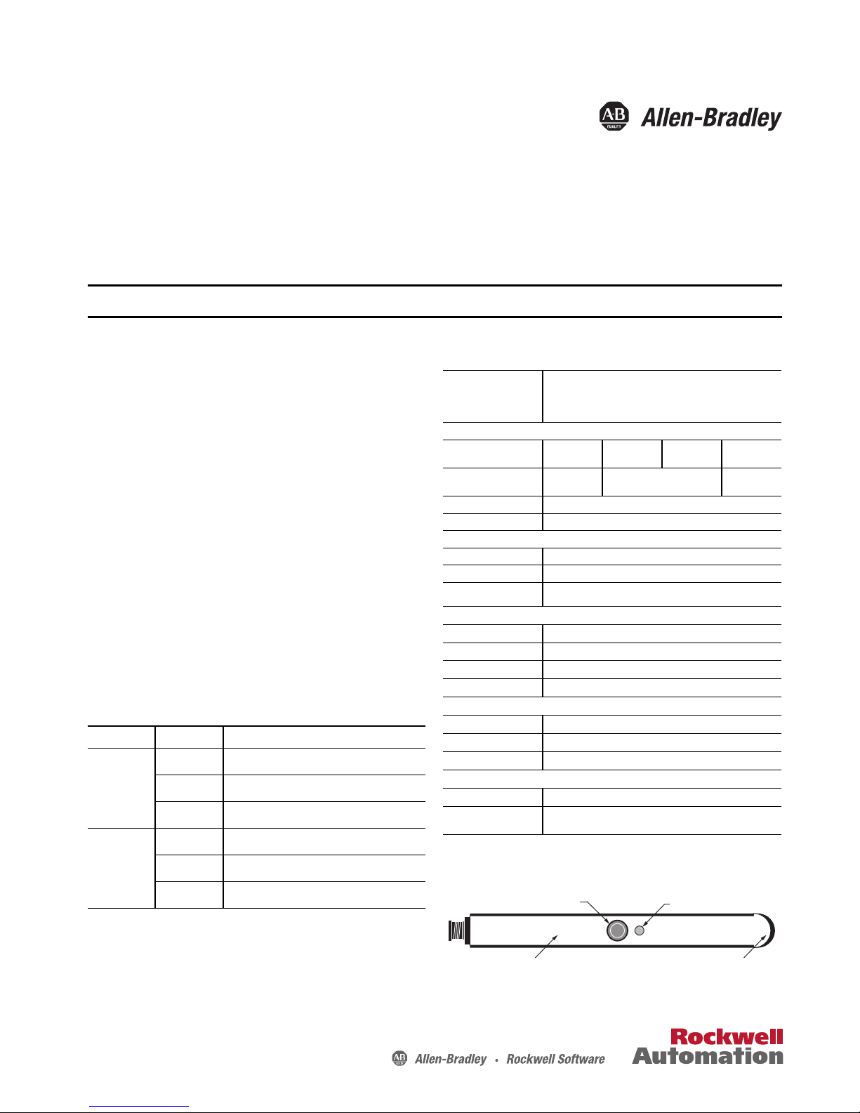
Allen-Bradley 45LSP-2LNA1-P3, 45LSP-2LNA2-P4, 45LSP-2LNA1-P4, 45LSP-2LNA2-P3, 45LSP-2LNA3-P3 Installation Instructions Manual
...Page 1
Installation Instructions
IMPORTANT
45LSP Optical Fork PHOTOSWITCH Photoelectric Sensors
Installation Instructions
Catalog Numbers: 45LSP-2LNA1-P3, 45LSP-2LNA1-P4, 45LSP-2LNA2-P3, 45LSP-2LNA2-P4, 45LSP-2LNA3-P3,
45LSP-2LNA3-P4, 45LSP-2LNA4-P3, 45LSP-2LNA4-P4, 45LSP-2LPA1-P3, 45LSP-2LPA1-P4, 45LSP-2LPA2-P3,
45LSP-2LPA2-P4, 45LSP-2LPA3-P3, 45LSP-2LPA3-P4, 45LSP-2LPA4-P3, 45LSP-2LPA4-P4
SAVE THESE INSTRUCTIONS FOR FUTURE USE. Refer to http://ab.rockwellautomation.com/ for additional information.
Description
The 45LSP is a family of optical fork sensors housed in a plastic
enclosure. Fork sensors offer self-contained transmitted beam sensing,
ideal for applications that require reliable parts detection. A simple
push button teach-in sensitivity adjustment, several connection options
and multiple mounting features (via side thru-holes, rear threaded
inserts or optional dovetail bracketry) make the 45LSP an economical,
easy-to-use solution for typical applications such as small part
detection, edge detection, part counting, gear tooth detection and
dimension verification.
Features
• Detection of objects as small as 0.2 mm (0.0078 in.)
• Highly visible power and output LED indicators with output
indication along both sides of the fork
• Remote teach and teach button lock on 4-pin models
• Light or dark operate selectable
• Multiple mounting options: thru-holes, threaded holes and
dovetail
• Easy installation with no alignment required
• IP67 enclosure
User Interface
LED Color State Status
OFF Output de-energized
Orange
Green
ON Output energized
Flashing Teach mode or short circuit protective active
OFF Power is OFF
ON Power is ON
Specifications
cULus and CE Marked for all applicable directives
Certifications
Optical
Sensing Gap
Smallest Detectable Target
Light Source Visible red (640 nm)
Sensitivity Adjustment Teach button and remote teach
Electrical
Voltage 10…30V DC
Current Consumption 30 mA maximum
Protection Reverse Polarity and short circuit
Outputs
Response Time 250 µs
Output Type PNP or NPN
Output Mode Light or dark operate selectable
Output Current 100 mA maximum
Mechanical
Housing Material Polycarbonate
Connection Types 3-pin pico QD, 4-pin pico QD
Optional Accessories 44B-BKT dovetail mounting bracket and cordsets
Environmental
Environmental Rating IP67
Operating Temperature
[C(F)]
1
For detection of objects less than 0.9 m (0.035 in.), the object should be placed ≥ 10 mm
(0.39in.) away from the LED light source.
For use in NFPA 79 applications only
Adapters providing field wiring means are available from the
manufacturer. Refer to manufacturers information.
30 mm
(1.18 in.)
0.2 mm
(0.07 in.)
-10…+60 ° (14…140 °
1
50 mm
(1.97 in.)
0.2 mm (0.007 in.)
80 mm
(3.15 in.)
120 mm
(4.72 in.)
0.4 mm
(0.02 in.)
Flashing Teach mode
Teach button
Orange LED
Green LED
Orange LED
Page 2
45LSP Optical Fork PHOTOSWITCH Photoelectric Sensors Installation Instructions
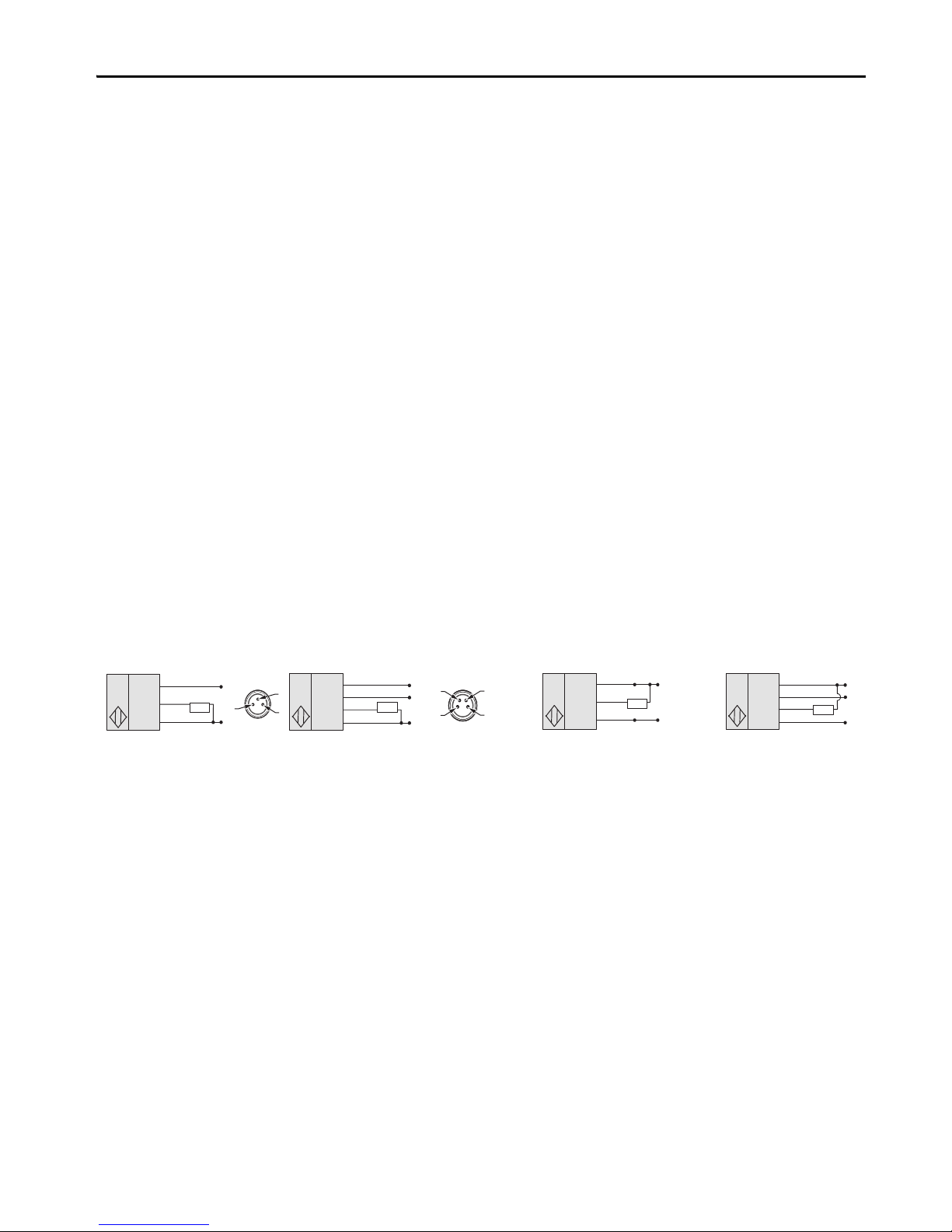
Brown (1)
+
–
Black (4)
White (2)
Blue (3)
Load
Brown (1)
Black (4)
White (2)
Blue (3)
Load
Brown (1)
+
–
Black (4)
Blue (3)
Load
Brown (1)
Black (4)
Blue (3)
Load
+
–
+
–
3
1
4
3
4
2
1
3-Pin
NPN ModelsPNP Models
4-pin3-pin4-pin
♦
♦
Operational Instructions
Sensitivity Adjustment
With no target present, press the teach button for approximately three
seconds until orange LEDs are flashing synchronously: first threshold is
taught. With the target present, press the teach button for
approximately one second. If the green LED flashes and stays on then
thresholds have been taught, and the sensor is ready to operate. If both
LEDs are flashing synchronously then the sensor cannot detect the
object and no thresholds have been taught.
Sensitivity Adjustment During a Running Process (optimum detection
of very small parts)
With the chosen running process being the only thing in the scanning
area, press the teach button for approximately three seconds until
orange LEDs are flashing synchronously. Press the teach button until a
minimum of one process cycle is completed. If the green LED flashes
and stays on then thresholds have been taught, and the sensor is ready to
operate. If both LEDs are flashing synchronously then the sensor
cannot detect the target and no thresholds have been taught.
L.O./D.O. Setup
Press the teach button for approximately 13 seconds. Orange LEDs
should flash alternately. When you release the button, the green LED
should remain flashing. When the green LED is flashing , the output is
inverted by pressing the button. The orange LED shows active
function. Do not press the button for 10 seconds. The green LED stops
flashing and the present output function is saved. The sensor is ready to
operate.
Maximum Sensitivity
With no target present, press the teach button for approximately three
seconds until orange LEDs are flashing synchronously. Again, with no
target present, press the teach button for one second. The sensor is set
to maximum sensitivity and is ready to operate.
Maximum Stability—Factory Setting (maximum resistance to
contamination)
Cover the light source. Press and hold the teach button until the orange
LEDs are flashing synchronously. Keep the light source covered, press
the teach button for one second. The sensor is set to maximum stability
and is ready to operate.
Modification of the Emitter Frequency in Case of Mutual Interference
Switch one sensor off. Press the teach button during power ON. The
orange LED flashes one time; frequency one, normal operation
(switching frequency 2 kHz). Keep the button pressed for another
three to five seconds. The orange LED flashes twice; frequency two,
normal operation (switching frequency 2 kHz). Keep the button
pressed for another three to five seconds. The orange LED flashes three
times; frequency one, detection of very small parts possible (switching
frequency 2 kHz). Keep the button pressed for another three to five
seconds. The orange LED flashes four times; frequency two, detection
of very small parts possible (switching frequency 1.5 kHz). Release the
button to place the sensor in operating mode. Switch other sensor on
again.
Wiring Diagrams
2 Rockwell Automation Publication 45LSP-IN001C-EN-P – November 2015
Page 3

45LSP Optical Fork PHOTOSWITCH Photoelectric Sensors Installation Instructions
C
Teach-in
button
4
E
D
A
B
GF
10
(0.39)
5
(0.2)
4.5 (0.18)
12 (0.47)
4.5 (0.18)
8 (0.31)
4.2 (0.17) 3x Dia.
Dimensions [mm (in.)]
Fork Type A B C D E F G H I
30 mm 30 (1.18) 50 (1.97) 30 (1.18) 34 (1.34) 59.5 (2.34) 20 (0.78) — 62.2 (2.45) 71.7 (2.82)
50 mm 50 (1.97) 70 (2.76) 50 (1.97) 54 (2.13) 79.5 (3.13) 20 (0.78) 28 (1.10) 82.2 (3.24) 91.7 (3.61)
80 mm 80 (3.15) 100 (3.93) 80 (3.15) 54 (2.13) 79.5 (3.13) 20 (0.78) 2 x 28 (2.20) 112.2 (4.42) 91.7 (3.61)
120 mm 120 (4.72) 140 (5.51) 120 (4.72) 54 (2.13) 79.5 (3.13) 20 (0.78) 3 x 28 (3.30) 152.2 (5.99) 91.7 (3.61)
Optional Accessories
Description Cat.
Dovetail mounting bracket 44B-BKT
2 m (6.5 ft) 3-pin DC pico QD
2 m (6.5 ft) 4-pin DC pico QD
No.
889P- F3AB -
889P- F4AB -
2
2
Rockwell Automation Publication 45LSP-IN001C-EN-P – November 2015 3
Page 4

Rockwell Automation Support
Rockwell Otomasyon Ticaret A.Ş., Kar Plaza İş Merkezi E Blok Kat:6 34752 İçerenköy, İstanbul, Tel: +90 (216) 5698400
Rockwell Automation provides technical information on the Web to assist you in using its products.
At http://www.rockwellautomation.com/support
You can also visit our Support Center at https://rockwellautomation.custhelp.com/
information, FAQs, and to sign up for product notification updates.
In addition, we offer multiple support programs for installation, configuration, and troubleshooting. For more information, contact your local
distributor or Rockwell Automation representative, or visit
http://www.rockwellautomation.com/services/online-phone
Installation Assistance
If you experience a problem within the first 24 hours of installation, review the information that is contained in this manual. Yo u ca n c ont ac t
Customer Support for initial help in getting your product up and running.
United States or Canada 1.440.646.3434
Outside United States or Canada
Use the Worl dwide Locato r
Automation representative.
New Product Satisfaction Return
Rockwell Automation tests all of its products to help ensure that they are fully operational when shipped from the manufacturing facility. However,
if your product is not functioning and needs to be returned, follow these procedures.
you can find technical and application notes, sample code, and links to software service packs.
for software updates, support chats and forums, technical
.
at http://www.rockwellautomation.com/rockwellautomation/support/overview.page, or contact your local Rockwell
United States
Outside United States Please contact your local Rockwell Automation representative for the return procedure.
Contact your distributor. You must provide a Customer Support case number (call the phone number above to obtain one) to your distributor to complete
the return process.
Documentation Feedback
Your comments will help us serve your documentation needs better. If you have any suggestions on how to improve this document, complete this
form, publication RA-DU002
U.S. Allen-Bradley Drives Technical Support - Tel: (1) 262.512.8176, Fax: (1) 262.512.2222, E-mail: support@drives.ra.rockwell.com
Online: www.ab.com/support/abdrives.
Rockwell Automation maintains current product environmental information on its website at
http://www.rockwellautomation.com/rockwellautomation/about-us/sustainability-ethics/product-environmental-compliance.page
, available at http://www.rockwellautomation.com/literature/.
.
Allen-Bradley, Rockwell Software, and Rockwell Automation are trademarks of Rockwell Automation, Inc.
Trademarks not belonging to Rockwell Automation are property of their respec tive companies.
Publication 45LSP-IN001C-EN-P – November 2015 10000033147 Ver 02
Copyright © 2015 Rockwell Auto mation, Inc. All rights reserved. Pr inted in the U.S.A.
 Loading...