

Allen-Bradley 440N-Z21S17H, 440N-Z21S16B, 440N-Z21S16A, 440N-Z21S16J, 440N-Z21S17A Installation Instructions Manual
...Page 1
SensaGuard
TM
18 mm Plastic Barrel
Installation Instructions
Certifications
IMPORTANT:
SAVE THESE INSTRUCTIONS FOR FUTURE USE
Note: Refer to Technical Specifications for Certification information and ratings.
Page 2

Table of Contents
Installation Instructions 3
Warnings 3
Technical Specification 3
Operating Characteristics 3
Outputs (internally fused) 3
Environmental 3
Protection 4
Dimensions 4
Mode of Operation 4
Status Indicators 4
Mounting Information 4
Nut Torque Specification 4
Minimum Distance Between Sensors 5
Misalignment Curve 5
Wiring Diagram 5
Recommended Mating Cable 5
Diagnostics 5
Troubleshooting 6
Application Wiring Examples 8
List of Recommended Relays 12
Maintenance 12
Repair 12
Declaration of Conformity 12
PA-75056-180-01(A), September 2006
2 SensaGuardTM18 mm Plastic Barrel Installation Instructions
Page 3
Installation Instructions
Installation must be in accordance with the following steps and stated specifications and should be
carried out by suitable competent personnel. The unit is not to be used as a mechanical stop. Guard
stops and guides must be fitted. Adherence to the recommended maintenance instructions forms part
of the warranty.
This device is intended to be part of the safety related control system of a machine. Before installation,
a risk assessment should be performed to determine whether the specifications of this device are suitable for all foreseeable operational and environmental characteristics of the machine to which it is to
be fitted. Refer to Technical Specifications for Certification information and ratings.
ATTENTION: The presence of spare actuators compromise the integrity of the safety sys-
tems. Personal injury or death, property damage or economic loss can result.
Appropriate management controls, working procedures and alternative protective measures should be introduced to control their use and availability.
WARNING: Do not defeat, tamper, remove or bypass this unit. Severe injury to personnel
could result. The sensor MUST be connected to a Class 2 SELV 24V DC,
+10% / -15% power supply.
Technical Specification
Safety Ratings CAT4/SIL3
Safety Certifications TÜV, CE
Safety Standards IEC60947-5-3, IEC61508, EN954
Certifications cULus
Standards UL 508
PFHd 1.119 - 10
-9
Operating Characteristics
Sensing Distance (Actuator) 18 mm 30 mm
Assured Make (mm) 15 25
Assured Break (mm) 25 35
Typical misalignment (±7 mm in both axes)
Maximum output current (all
outputs, mA) 200
Input Current 50 mA (no load supply current)
Operational Current, Min. ≤ 1 mA DC
Off-state Current < 0.5 mA DC
Maximum # of switches, connected in series Unlimited. See unit response time section
Operating Voltage 24V DC +10% / -15%
Class 2 SELV power supply
Frequency of operating cycle 1 Hz
Response Time (Off) 54 ms
Case Material Valox
®
DR 48
Actuator Material Valox
®
DR 48
Outputs (internally fused)
OSSD 2
Auxiliary 1
Environmental
Operating Temperature -10…+55°C (+14…+131°F)
Operating Humidity 5% -95% relative
Washdown rating NEMA 3, 4X, 12,13, IP 69K
Shock & Vibration IEC68-2-27 30 g, 11 ms/IEC 68-2-6
10…55Hz
Radio Frequency IEC 61000-4-3
IEC 61000-4-6
PA-75056-180-01(A), September 2006
SensaGuardTM18 mm Plastic Barrel Installation Instructions 3
Page 4
Protection
Short-Circuit Protection Incorporated
Current limitation Incorporated
Overload Protection Incorporated
False Pulse Protection Incorporated
Transient Noise Protection Incorporated
Reverse Polarity Protection Incorporated
Overvoltage protection Incorporated
Thermal shutdown/restart Incorporated
Electrical Life 10 x 10
6
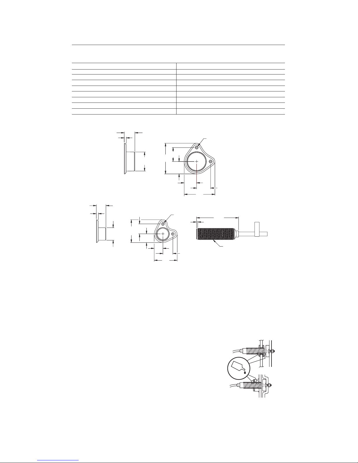
Dimensions - mm (inches)
Mode of Operation
Status indicators:
• “Power/Fault” LED illuminates Green - The unit is ready for operation.
• “Power/Fault” LED illuminates Red: - Door/Guard open. The unit is not ready for operation.
• “Power/Fault” LED illuminates flashes Red or Green: - Unit failure. See Diagnostic section below.
Mounting Information
Use non-removable screws, bolts, or nuts to mount the switch and
actuator. Do not over torque the mounting hardware.
Position the switch and actuator so they are aligned with each other.
Mount the switch and actuator to removable guard, door or gate.
Keep the switch and actuator within the sensing range below.
Nut Torque Specification
Plastic Barrel Switch: 2.26 N•M (20 in•lbs)
Plastic Actuators: 2.26 N•M (20 in•lbs)
PA-75056-180-01(A), September 2006
4 SensaGuardTM18 mm Plastic Barrel Installation Instructions
30 mm Actuator
48.92
[1.926]
19.81
[0.78]
22.22
[0.875]
48.92
[1.926]
19.81
[0.78]
22.22
[0.875]
30.40
[1.197]
16.84
[0.663]
3.17
[0.125]
4.57
[0.18]
DIA
2 PLACES
Sensor
18 mm Actuator
67.06
[2.640]
2.03
[.080]
M18X1
36.47
[1.436]
13.72
[0.54]
15.87
[0.625]
36.47
[1.436]
13.72
[0.54]
15.87
[0.625]
4.57
[0.180]
DIA
19.81
[0.78]
3.17
[0.125]
15.42
[0.607]
2 PLACES
Page 5

Minimum Distance Between Sensors
Misalignment Curve
18 mm Unit with 18 mm Target 18 mm Unit with 30 mm Target
Note: There must be a minimum spacing of 4 mm
(0.157 in) if actuator and sensor face approaches
laterally. This will prevent false triggering due to the
side lobe areas.
Wiring Diagram
Pin # Wire Color Signal
1 White Aux Outputs
2 Brown +24V
3 Green NA
4 Yellow OSSD 2, +24V Input
5 Grey OSSD 1
6 Pink OSSD 2
7 Blue 0V
8 Red OSSD 1, +24V Input
Recommended mating cable, 2 m (6.5 ft). 889D-F8AC-2. Lengths are available up to 30 m (98.4 ft)
Diagnostic
Unit Indicators (per IEC 60073)
State Status Troubleshooting
Off Not Powered NA
Device Output Red Not Safe, OSSD not active NA
LED Green Safe, OSSD active NA
Green flash Power up test or OSSD Check 24V DC or OSSD inputs
inputs not valid (yellow and red wire)
Red Flash 1 Hz Flash Recoverable Fault Recoverable fault —check OSSD
4 Hz Flash Non-recoverable Fault outputs are not shorted to GND,
24V DC or each other. Cycle power.
PA-75056-180-01(A), September 2006
SensaGuardTM18 mm Plastic Barrel Installation Instructions 5
18 mm Actuator
75 mm
Sensor
1
Senso
r
2
30 mm Actuator
100 mm
Sensor
1
Senso
r
2
Lateral Misalignment Tolerance—mm (in
)
Face to Face Distance—mm
-15
(-0.59)
-10
(-0.39)
-5
(-0.19)
0
5
(0.19)
10
(0.39)
15
(0.59)
0
5
10
15
20
25
-25
(-0.98)
-20
(-0.787)
20
(0.787)
25
(0.98
)
Side Lobe Side Lobe
Assured Sensing
Distance
OFF OFF
ON
0
5
10
15
20
25
30
35
-30
(-1.18)
-20
(-0.787)
-10
(-0.39)
010
(0.39)20(0.787)30(1.18)
Face to Face Distance—mm
Side Lobe Side Lobe
Assured Sensing
Distance
OFF OFF
ON
Lateral Misalignment Tolerance—mm (in)
Note: There must be a minimum spacing of 7
mm (0.275 in) if actuator and sensor face
approaches laterally. This will prevent false
triggering due to the side lobe areas.
476
8
1
5
2
3
Brown
White
Blue
Pink
Grey
Green
Red
Yellow
Note: Refer to Technical Specifications for Certification information and ratings.
Page 6

Troubleshooting
Series Circuit
PA-75056-180-01(A), September 2006
6 SensaGuardTM18 mm Plastic Barrel Installation Instructions
Ye l
Red
Brown
Gray
Pink
Blue
24VDC
Power
Supply
1606
-XL120D
Switch 1
+24
RTN
Switch 2
White
White
Ye l
Red
Brown
Gray
Pink
Blue
Actuator 1
Actuator 2
Switch 3
White
Ye l
Red
Brown
Gray
Pink
Blue
Actuator 3
Switch 4
White
Ye l
Red
Brown
Gray
Pink
Blue
Actuator 4
Switch 5
White
Ye l
Red
Brown
Gray
Pink
Blue
Actuator 5
+24 V
+24 V
+24 V
+24 V
+0 V
+0 V
+0 V
+0 V
+0 V
+0 V
Actuator 2 is in sensing range.
Switch
2 is functioning properly
OSSDs are energize to 24 V
Green LED is ON.
Actuator 3 is in sensing range.
Switch
3 has fault.
See Table Above—Red LED is flashing
Actuator 1 is in sensing range.
Switch
1 is functioning properly
OSSDs are energize to 24 V
Green LED is ON.
Actuator 4 is in sensing range.
Switch
4 is functioning properly.
Series inputs are 0 V.
OSSDs are de-energized to 0V .
Green LED is Flashing to indicate
Series inputs are not 24V.
Actuator 5 is in sensing range.
Switch
5 is functioning properly .
Series inputs are 0V .
OSSDs are de-energized to 0V.
Green LED is Flashing to indicate
Series inputs are not 24V.
OSSD’ s are OF
F
Recoverable fault
Note: Refer to Technical Specifications for Certification information and ratings.
Page 7

Unit Response Time (does not include safety relay response time)
PA-75056-180-01(A), September 2006
SensaGuardTM18 mm Plastic Barrel Installation Instructions 7
Yel
Red
White
Gray
Pink
Blue
24V DC
Power
Supply
1606
Sensor 1
+24
RT
Sensor 2
Brown
Brown
Gray
Pink
White
Yel
Red
Blue
Sensor 3
Brown
Yel
Red
White
Gray
Pink
Blue
A1
S21
S11 41332313S12S52
42342414A2S34S22
440R-N23126
Actuator 1
Actuator 2
Actuator 3
Initial Conditions:
All actuators are in sensing
distance.
Actuator 1 is moved out of
sensing range.
Sensor 2 drops the 24 volts
(red and yellow) from Sensor 1
OSSD outputs.
Green LED flashes.
Sensor 3 drops the 24 volts
(red and yellow) from Sensor 2
OSSD outputs.
Green LED flashes.
0 mS
54 mS 72 mS 90 mS
Actuator 1 is out of sensing
range.
Actuator 2 and 3 are in
sensing range.
Actuator 1 is moved into sensing
range.
Sensor 1 OSSD outputs are
energized.
Sensor 2 OSSD inputs (red and yellow)
transition to 24V DC from Sensor 1
OSSD outputs.
Sensor 2 OSSD outputs are energized
Sensor 3 OSSD inputs (red and
yellow) transition to 24V DC from
Sensor 2 OSSD outputs.
Sensor 3 OSSD outputs are
energized.
0 mS
360 mS 378 mS 396 mS
OFF
ON
Note: Refer to Technical Specifications for Certification information and ratings.
Page 8

Application Wiring Examples
PA-75056-180-01(A), September 2006
8 SensaGuardTM18 mm Plastic Barrel Installation Instructions
K1
+24V DC
MSR127RP with 1 sensor, monitored manual reset, drivin
g
100S or 700S safet
y
controllers.
A1 S11
S52 S12
13
23 33
41
S21
S22
S34
A2
14 24 34 42
MSR127RP
Reset
GND
Blue
Gray
Pink
Yel lo w
Red
Brown
SensaGuard
Unit 1
K2
+24V DC
GND
MSR127RP with 3 sensors in series, monitored manual reset, drivin
g
100S or 700S safet
y
controllers
Blue
Gray
Pink
Yellow
Red
Brown
SensaGuard
Unit 1
SensaGuard
Unit 2
SensaGuard
Unit 3
K1
A1 S11
S25 S12
13
23 33
41
S21 S22 S34 A2 14 24 34 42
MSR127RP
Reset
K2
Blue
Gray
Pink
Yellow
Red
Brown
Blue
Gray
Pink
Yellow
Red
Brown
MSR127RP with 3 sensors and 1 440L light curtain in series, monitored manual reset, driving 100S or 700S safety relays.
Note: Light curtain must be last (farthest from MSR127).
GND
A1 S11
S52 S12
13
23 33
41
S21 S22 S34 A2 14 24 34 42
MSR127RP
Reset
K1
K2
+24V DC
Blue
Gray
Pink
Yel l ow
Red
Brown
SensaGuard
Unit 1
SensaGuard
Unit 2
SensaGuard
Unit 3
GuardShield
Blue
Gray
Pink
Yel l ow
Red
Brown
Blue
Gray
Pink
Yel l ow
Red
Brown
Blue
Gray
Pink
Yel l ow
Red
Brown
A1 S11
S52 S12
13
23 33
41
S21
S22
S34
A2
14 24 34 42
MSR127TP
GND
MSR127RP with 1 sensor, automatic reset, drivin
g
100S or 700S safet
y
controllers
+24V DC
SensaGuard
Unit 1
K1
K2
Blue
Gray
Pink
Yellow
Red
Brown
Note: Refer to Technical Specifications for Certification information and ratings.
Page 9

Application Wiring Examples
PA-75056-180-01(A), September 2006
SensaGuardTM18 mm Plastic Barrel Installation Instructions 9
MSR127TP with 3 sensors in series, automatic reset, drivin
g
100S or 700S rela
y
s.
MSR127TP
+24V DC
GND
Blue
Gray
Pink
Yel lo w
Red
Brown
SensaGuard
Unit 1
K1
A1 S11
S52 S12
13
23 33
41
S21 S22 S34 A2 14 24 34 42
K2
Blue
Gray
Pink
Yel lo w
Red
Brown
Blue
Gray
Pink
Yel lo w
Red
Brown
SensaGuard
Unit 3
SensaGuard
Unit 2
MSR127TP with 3 sensors and 1 440L light curtain in series, automatic reset, driving 100S or 700S safety contactors.
Note: Light curtain must be last (farthest from MSR127)
MSR127TP
GND
A1 S11
S52 S12
13
23 33
41
S21 S22 S34 A2 14 24 34 42
K1
K2
+24V DC
Blue
Gray
Pink
Yel lo w
Red
Brown
Blue
Gray
Pink
Yel lo w
Red
Brown
Blue
Gray
Pink
Yel lo w
Red
Brown
Blue
Gray
Pink
Yel lo w
Red
Brown
GuardShield
SensaGuard
Unit 1
SensaGuard
Unit 3
SensaGuard
Unit 2
Note: Refer to Technical Specifications for Certification information and ratings.
Page 10

Application Wiring Examples
PA-75056-180-01(A), September 2006
10 SensaGuardTM18 mm Plastic Barrel Installation Instructions
MSR200 series with 3 sensors and 1 440L light curtain, automatic reset, driving 100S or 700S safety contactors.
Note: Li
g
ht curtain can be attached to an
y
in
p
ut
GuardShield
+24V DC
GND
440R-H23177
Y40 Y41S51S12 S20 S32 S11 S21 S31 S41 13 23 31 Y42 A1S32S20S12
S42 S50 S62 S34 Y1 Y2 Y3 14 24 32 Y32 Y33 Y30 A2S62S50S42
440R-H23179
K1
S32S20S12
S62S50S42
S32
S32
440R-H23180
MSR221P MSR211P
MSR230P
K2
K1
K2
K3
K4
SensaGuard
Blue
Brown
GrayPink
Blue
Brown
Yellow
Red
GrayPink
SensaGuard SensaGuard
GrayPink GrayPink
Blue
Brown
Yellow
Red
Blue
Brown
Yellow
Red
MSR200 series with 4 sensors and 1 440L light curtain, manual reset, driving 100S or 700S safety contactors.
Note: Li
g
ht curtain can be attached to an
y
in
p
ut.
Reset
GuardShield
+24V DC
GND
440R-H23177
Y40 Y41S51S12 S20 S32 S11 S21 S31 S41 13 23 31 Y42 A1S32S20S12
S42 S50 S62 S34 Y1 Y2 Y3 14 24 32 Y32 Y33 Y30 A2S62S50S42
440R-H23179
K1
S32S20S12
S62S50S42
S32
S32
440R-H23180
MSR221P MSR211P
MSR230P
K2
K1
K2
K3
K4
SensaGuard
Blue
Brown
GrayPink
Blue
Brown
Yellow
Red
GrayPink
SensaGuard SensaGuard
GrayPink GrayPink
Blue
Brown
Yellow
Red
Blue
Brown
Yellow
Red
Note: Refer to Technical Specifications for Certification information and ratings.
Page 11

Application Wiring Examples
PA-75056-180-01(A), September 2006
SensaGuardTM18 mm Plastic Barrel Installation Instructions 11
MSR200 series with 4 sensors, automatic reset, driving 100S or 700S safety contactors.
Yel l ow
Red
+24V DC
GND
440R-H23177
Y40 Y41S51S12 S20 S32 S11 S21 S31 S41 13 23 31 Y42 A1S32S20S12
S42 S50 S62 S34 Y1 Y2 Y3 14 24 32 Y32 Y33 Y30 A2S62S50S42
440R-H23179
K1
S32S20S12
S62S50S42
S32
S32
440R-H23180
MSR221P MSR211P
MSR230P
K2
K1
K2
K3
K4
SensaGuardSensaGuard
Blue
Brown
GrayPink
Blue
Brown
Yel l ow
Red
GrayPink
SensaGuard SensaGuard
GrayPink GrayPink
Blue
Brown
Yel l ow
Red
Blue
Brown
Yel l ow
Red
MSR200 series with 4 sensors, manual reset, drivin
g
100S or 700S safet
y
contactors.
Reset
+24V DC
GND
440R-H23177
Y40 Y41S51S12 S20 S32 S11 S21 S31 S41 13 23 31 Y42 A1S32S20S12
S42 S50 S62 S34 Y1 Y2 Y3 14 24 32 Y32 Y33 Y30 A2S62S50S42
440R-H23179
K1
S32S20S12
S62S50S42
S32
S32
440R-H23180
MSR221P MSR211P
MSR230P
K2
K1
K2
K3
K4
SensaGuardSensaGuard
Blue
Brown
GrayPink
Blue
Brown
Yellow
Red
Yellow
Red
GrayPink
SensaGuard SensaGuard
GrayPink GrayPink
Blue
Brown
Yellow
Red
Blue
Brown
Yellow
Red
Note: Refer to Technical Specifications for Certification information and ratings.
Page 12

List of recommended relays
MSR126, MSR127, MSR123, MSR124, MSR131, MSR138, MSR211, MSR121, MSR320, MSR200
Family (Except MSR210), MSR300 Family, SmartGuard, 1791 DS DeviceNet™ Safety I/O
Maintenance
Every week.
Check the correct operation of the switching circuit. Also check for signs of abuse or tampering.
Inspect the switch casing for damage
Repair
If there is any malfunction or damage, no attempts at repair should be made. The unit should be
replaced before machine operation is allowed.
Declaration of Conformity
This is to declare that the products shown on this document conforms with the Essential Health and
Safety Requirements (EHSR’s) of the European Machinery Directive (73/23/EEC as amended by
93/68/EEC). These products also conform to EN 60947-5-3, EN 1088, EN292, EN 60204-1 and have
Third Party Approval.
For a comprehensive certificate please visit: www.ab.com/safety.
Publication 75056-180-01(A), September 2006
12 SensaGuardTM18 mm Plastic Barrel Installation Instructions
Check the machine is
isolated and stopped
whenever the interlocked
guard door is open.
IMPORTANT: After
installation and
commissioning, the
actuator, switch and switch
lid fixing screws should be
coated with tamper evident
varnish or similar compound.
o
 Loading...