

Page 1
Installation Instructions
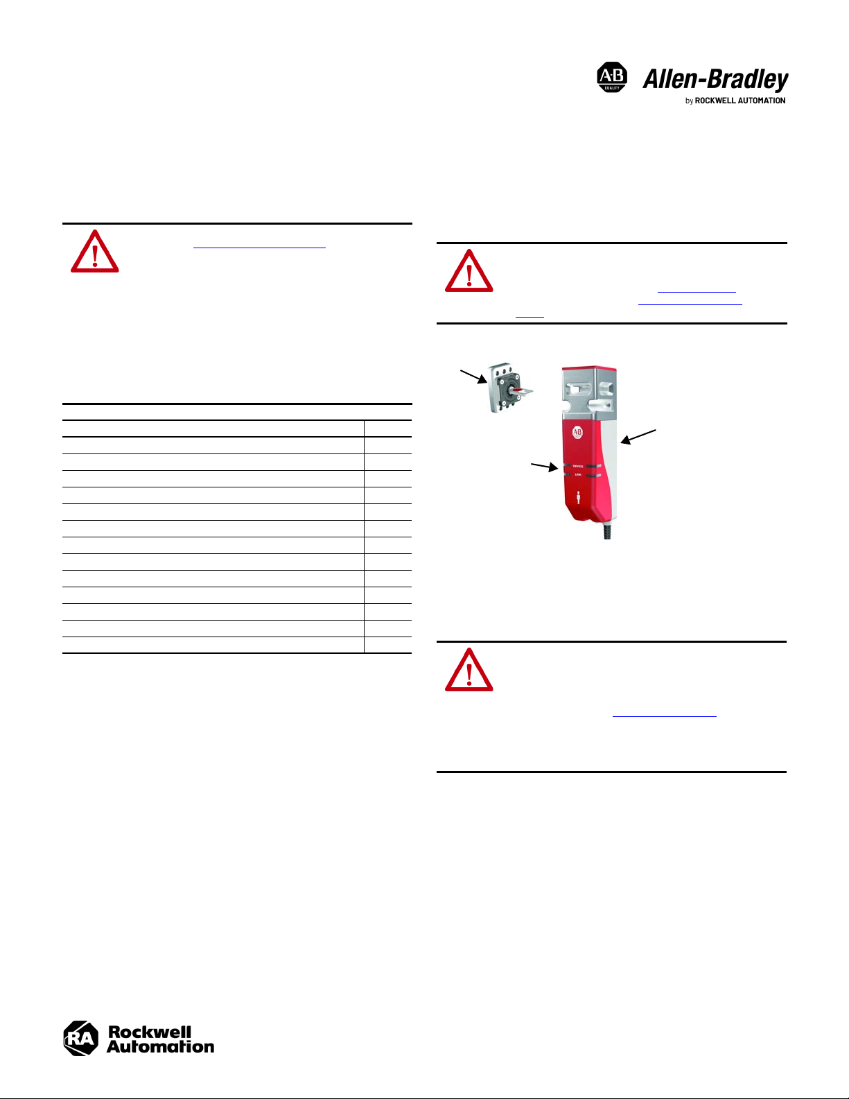
Actua tor
Switch body
LINK and DEVICE
status indicators
Original Instructions
440G-MZ Guardmaster Safety Switches
Catalog Numbers
Top ic Pa ge
Introduction 1
Installation 2
Commissioning — Unique Coded Models 2
Auxiliary Release 3
Approximate Dimensions 3
Pin Assignment 4
Connection in a GuardLink System 4
Specifications 4
Status Indicators 5
Lock Command 5
Catalog Number Explanation 5
Accessories 5
Additional Resources 5
440G-MZS20SNRJ, 440G-MZS20UNRJ, 440G-MZS20SNLJ, 440GMZS20UNLJ
ATTENTION: Read this document and the documents that
are listed in Additional Resources on page 5 about
installation, configuration, and operation of this equipment
before you install, configure, operate, or maintain this
product. Users are required to familiarize themselves with
installation and wiring instructions, and requirements of all
applicable codes, laws, and standards.
Only suitably trained personnel must perform activities
including installation, adjustments, commissioning, use,
assembly, disassembly, and maintenance in accordance
with applicable code of practice.
If this equipment is used in a manner that the manufacturer
does not specify, the protection that is provided by the
equipment may be impaired.
Introduction
ATTENTION: Do not attempt to install this device unless the
installation instructions have been studied and understood.
This document acts as a guide for a typical installation and
is available in some languages at rok.auto/literature. A user
manual is also available (see Additional Resources on
page 5).
Figure 1 - Assembly Overview
The 440G-MZ Guardmaster® Guard Locking Switch locks a guard door in the closed
position and does not release it until the hazardous machine functions that are
covered by the guard are in a safe condition. The safety control system only allows
the hazardous machine functions to operate when the guard is closed and locked.
Qualified personnel must install the switch in accordance with these instructions.
ATTENTION: This device is intended to be part of the safetyrelated control system of a machine. Before installation, a
risk assessment must be performed to determine whether
the specifications of this device are suitable for all
foreseeable operational and environmental characteristics
of the application. See Specifications on page 4 for
certification information and ratings.
Use appropriate screws, bolts, or nuts that are fitted by tools
to mount the switch and actuators to avoid the risk of
tampering. Do not over torque the mounting hardware.
Page 2
440G-MZ Guardmaster Safety Switches Installation Instructions
3 x M5
2 x M5
100 (3.94)
1
2
3
White
Gray
NC
Gnd 0V
NC
NC
+24V DC
Blue
Black
Brown
889D-F5NC-x
or
889D-F5BC-x
DEVICE
LINK
Installation
ATTENTION: Do not defeat, tamper, remove, or bypass this
unit. Severe injury to personnel could result.
The presence of spare actuators can compromise the
integrity of the safety systems. Personal injury or death,
property damage, or economic loss can result. Appropriate
management controls, working procedures, and alternative
protective measures should be introduced to control their
use and availability.
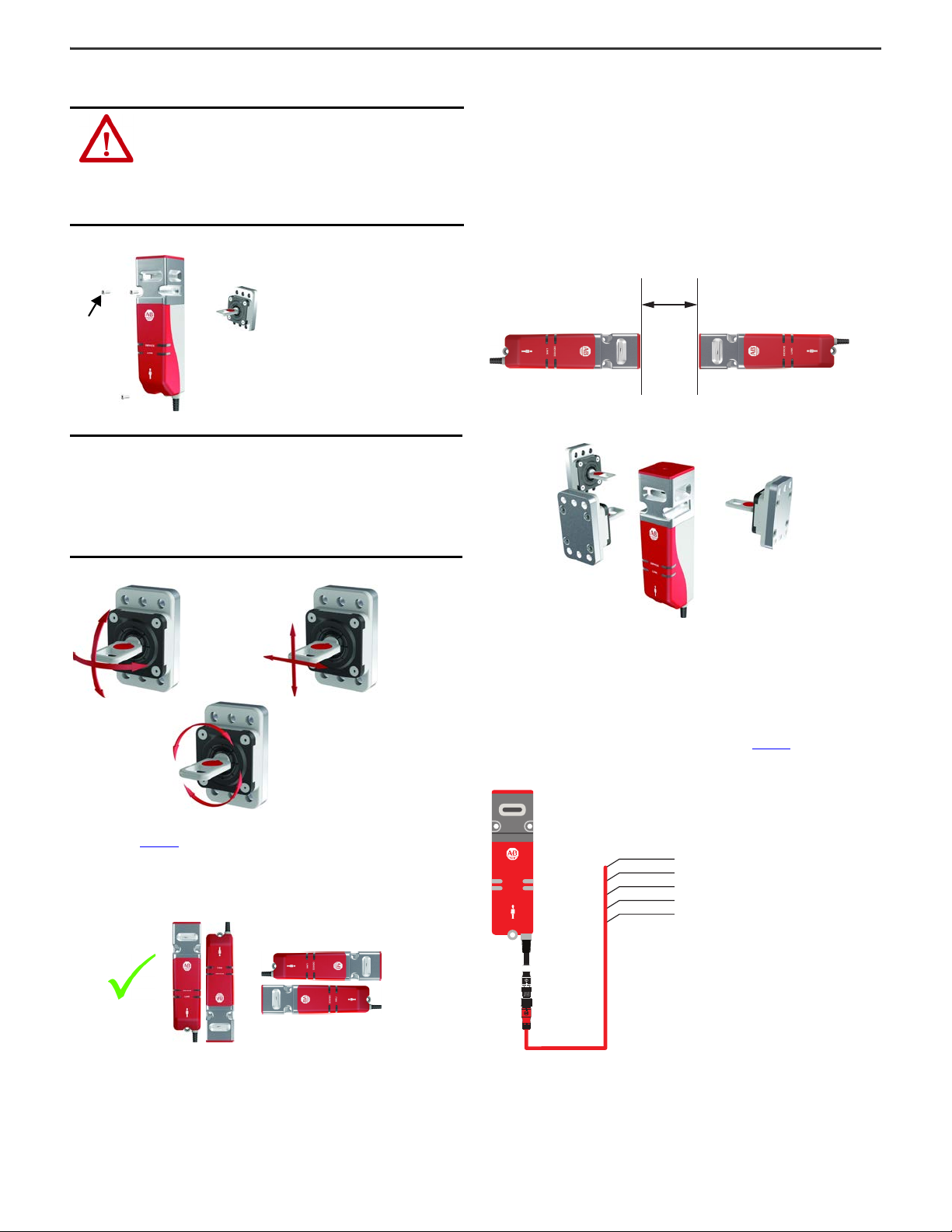
Figure 2 - Required Mounting Hardware for Switch and Actuator
IMPORTANT
Washers are not required and if used can cause the
mounting holes on the switch body to crack. If standard
thread locking compound is used on the mounting
screws of the switch body, check the manufacturer’s
specification. Many standard thread-locking compounds
can attack the plastic feet of the switch body, which can
cause stress cracks. It is recommended to use
cyanoacrylate-type thread-locking compounds.
Minimum Distance Between Switches
If a pair of 440G-MZ safety switches are mounted too close to one another, the two
magnetic fields interact causing crosstalk, which results in nuisance faults and
false operation.
A minimum of 100 mm (3.94 in.) must separate a pair of switches to help achieve
correct operation.
This restriction applies to any pair of Guardmaster safety switches that use RFID
sensing technology, including 440N-Z SensaGuard™ interlocks, or TLS-Z and
440G-LZ guard locking switches.
Figure 5 - Minimum Distance between Switches [mm (in.)]
Figure 6 - Three Directions of Approach
Figure 3 - Actuator Function
The flexible actuator bends, rotates, and slides to accommodate guard door
misalignment (Figure 3
). For optimal performance, verify that the locking bolt can
enter and withdraw from the tongue actuator without binding. A separately
mounted door latch is recommended to avoid door misalignment.
Figure 4 - Orientation of Assembled Switch
Commissioning — Unique Coded Models
The actuator teach process is not performed at the factory and must be performed
when the switch is first put into use. After the first-time learn, this process can be
repeated up to seven more times with unique coded replacement actuators.
During commissioning, connect the switch as shown in Figure 7
Figure 7 - Wiring
.
2 Rockwell Automation Publication 440G-IN018B-EN-P - April 2020
Page 3

440G-MZ Guardmaster Safety Switches Installation Instructions
5 (0.2)
Top View
2 x Ø5.5
(0.22)
33
(1.3)
6
(0.24)
153 (6.02)
134.5 (5.3)
33 (1.3)
14.9 (0.59)
22.5
(0.89)
176.8 (6.96)
15 (0.59)
5.9
(0.23)
15
(0.59)
Ø5.1
(0.2)
22.6
(0.89)
25.3
(1)
50
(1.97)
47.5
(1.87)
39.5
(1.56)
0.3
(0.01)
153 (6.02)
134.5 (5.3)
182.7 (7.19)
45.2
(1.78)
9.9
(0.39)
12.5
(0.49)
4
(0.16)
59.3
(2.33)
4 x Ø6.5
(0.26)
6 x Ø6.3 (0.25)
30
(1.18)
15
(0.59)
65 (2.56)
30
(1.18)
Ø32.9 (1.3)
50 (1.97)
7.5
(0.3)
7.3 (0.28)
25.6 (1.01)
12.8 (0.5)
10
(0.39)
14
(0.55)
14
(0.55)
20
(0.79)
10
(0.39)
23.7
(0.93)
Ø12.4
(0.49)
3 (0.12)
40
(1.57)
23.8
(0.94)
32.5
(1.28)
First Time Learn
Apply power to the switch without the actuator present. After the switch completes
the power sequence (approximately 8 seconds), the status indicator flashes green
eight times, which indicates the total number of times a new actuator can be
learned. This status indicator sequence repeats until an actuator is inserted in the
switch (in the guard closed position).
Table 1 - Commissioning Process for Unique Coded Switches
Step State Approximate Duration LED Indicators
1Actuator Present 15 s
• Flashing 8x green, repeating
• Solid red (learning a
replacement actuator)
2Verifying Actuator 15 s Flashing red/green, slow
3 Programming Switch 15 s Flashing red/green, fast
4 Program Finalization 15 s
Run Mode
(2)
After teaching a new actuator, a power cycle is required
5
(1) Out of box condition only.
(2) When teaching an actuator, the switch must be unlocked to insert the actuator. At the completing
program finalization, the switch remains unlocked and in the safe state.
IMPORTANT
—Solid red
Flashing green (number of times
a new actuator can be learned)
to complete the process.
Learn Additional Replacement Actuators
The switch automatically starts a new teach process (Table 1) when a unique coded
replacement actuator is inserted in the switch (in the guard closed position).
Auxiliary Release
Operation of the auxiliary release causes a fault condition.
To reset the switch, cycle the power or issue a RESET command over the link in a
GuardLink® safety system.
Figure 8 - Auxiliary Release Operation [mm (in.)]
(1)
Approximate Dimensions
Figure 9 - Switch Body [mm (in.)]
IMPORTANT
When the switch learns a new actuator, it no longer
recognizes previously learned actuators.
Lock the Actuator Code
If the actuator is removed from the switch and then reinserted into the switch
during the 15-second Program Finalization stage (see Step 4 in Table 1), this action
triggers the switch to LOCK the actuator code. This action can be performed during
any of the eight unique coded actuator learn cycles.
IMPORTANT
After a unique coded actuator is locked using this
method, the switch cannot learn additional replacement
actuators for the remaining life of the switch. If the
actuator is lost or damaged, the switch must be
replaced.
Error Codes
The following indicator patterns repeat until a Power Off/On cycle is completed.
Status/Diagnostic Indicator Error Code
Red-red-red-green Cannot learn a standard actuator
Red-red-red-green-green Actuator already learned
Red-red-red-green-green-green Bad RFID; actuator moved out of range
Red-red-red-green-green-green-green Exceeded learning eight actuators
Red-red-red-green-green-green-green-green Unit locked: cannot learn another actuator
Rockwell Automation Publication 440G-IN018B-EN-P - April 2020 3
Figure 10 - Actuator [mm (in.)]
Page 4

440G-MZ Guardmaster Safety Switches Installation Instructions
440G-MZ
5-wire Patchcord
(1), (2)
889D-F5NCDM-
x
Cordset
(3)
889D-F4NE-
y
4-wire Patchcord
(2), (4)
889D-F4NEDM-x
440S-PF5D
Brown
Blue
+24V DC
0V
440R-ENETR 440R-DG2R2T
White (S12) Black (S22)
OSSD
Unlock
Reset
Pin Assignment
Table 2 - 5-pin Micro (M12)
Pin Color
1 Brown +24V +24V
2 White Safety A Safety In
3Blue 0V 0V
4Black Safety B Safety Out
5GrayLock Command
(1) The recommended cordset is catalog number 889D-F5AC-2 (2 m [6.5ft]). For additional lengths,
replace the 2 with 5 [5 m (16.4 ft)] or 10 [10 m (32.8 ft)] for standard cable lengths.
The recommended patchcord for use with ArmorBlock® Guard Safety I/O is the 2 m (6.5 ft) catalog
number 889D-F5ACDM-2. Replace the 2 with 0M3 [0M3 (0.98 ft)], 1 [1 m (3.28 ft)], 5 [5 m (16.4 ft)], or 10
[10 m (32.8 ft)] for standard cable lengths.
Connection in a GuardLink System
The 440G-MZ safety switch can be connected to a GuardLink system via a passive
tap (catalog number 440S-PF5D shown in Figure 11) or a passive power tap (catalog
number 440S-PF5D4).
Figure 11 - Connect 440G-MZ Switch to a GuardLink System with a Passive Tap
(1) 10 m (32.8 ft) length, max.
(2) Replace
(3) Replace
(4) 30 m (98.4 ft) length, max
x
with 0M3 (300 mm [0.98 ft]), 0M6 (600 mm [1.97 ft]), 1 (1 m [3.3 ft]), 2 (2 m [6.6 ft]),
5 (5 m [16.4 ft]), or 10 (10 m [32.8 ft]) for standard cable lengths.
y
in order number with 2 (2 m [6.6 ft]), 5 (5 m [16.4 ft]), 10 (10 m [32.8 ft]), 15 (15 m [49.2 ft]),
20 (20 m [65.6 ft]), or 30 (30 m [98.4 ft]) for standard cable lengths.
(1)
5
3
2
1
4
Function
OSSD Mode GuardLink Mode
Command, Lock, and
Unlock (CLU)
Specifications
Attribute Value
Standards IEC 60947-5-3, IEC 61508, ISO 13849-1, IEC 62061, ISO 14119, UL 508
Type 4 interlocking device with guard locking per ISO 14119 with
Safety classification
Functional safety data See publication SAFETY-SR001
Certifications CE Marked for all applicable EU directives, c-UL-us, TÜV
Operating Characteristics
Torque for M5 mounting of switch
and actuator mounting bracket
Locking bolt alignment tolerance
X, Y, Z
Holding force F
(ISO 14119)
Holding force F
(ISO 14119)
Output current, max (each output) 200 mA
Quiescent power consumption,
locked or unlocked
Lock signal current 1 mA
Peak current and duration, at turn
on or after lock/unlock operation
Steady state current, max
Operating voltage Ue 24V DC +10% / -15% Class 2 PELV
Operating cycle frequency, max 0.2 Hz
Dwell time between subsequent
locking/unlocking
Response time (Off)
(IEC 60947-5-3)
Start up time (availability) 8 s
Utilization category
(IEC 60947-5-2)
Insulation voltage U
(IEC 60947-5-1)
Impulse withstand voltage U
(IEC 60947-5-1)
Pollution degree
(IEC 60947-5-1)
Auxiliary release Built in
Protection class
(IEC 61140)
Mechanical life 500,000 cycles
Outputs (Guard door is closed and locked)
Safety outputs 2 x PNP, 0.2 A max / ON (+24V DC)
Environmental
Operating temperature 0…55 °C (32…131 °F)
Storage temperature -25…+75 °C (-13…+167 °F)
Operating humidity 5…95%, noncondensing
Enclosure ingress rating IP65, IP66, IP67, IP69K
Shock and vibration
Radio frequency/EMC IEC 60947-5-3, FCC-1 (Parts 18 and 15), RED
General
Materials
Weig ht
Protection Type
max
zh
i
low (standard) and high (unique) coding per ISO 14119
Suitable for use in applications up to and including PLe Cat 4 per
ISO 13849-1, SIL CL 3 per IEC 62061, and SIL 3 per IEC 61508.
2 N•m (17.7 lb•in) max
±5 mm (0.2 in.) max
3250 N
2500 N
1.5 W
150 mA for approximately 800 ms following lock/unlock operation.
OSSD mode: 40 mA
GL mode: 50 mA
2.5 s
275 ms
DC-13 24V 200 mA
75V
imp
1 kV
3
Class II
IEC 60068-2-27, 30 g (1.1 oz), 11 ms/IEC 60068-2-6, 10…55 Hz,
1mm(0.4in.)
• Switch: Housing - ABS, front brace – SS304 (machined), SS316
(cast)
• Actuator: Housing and housing cover – SS304, spring – SS302,
grommet – nitrile rubber, screws - stainless steel, tongue –
SS410
• Brackets: High Strength Low Alloy Steel
• Padlock Accessory: SS410
• Switch: 0.75 kg (1.7 lb)
• Actuator: 0.27 kg (0.6 lb)
• Actuator L mounting bracket: 0.27 kg (0.6 lb)
• Actuator Z bracket: 0.54 kg (1.2 lb)
• Switch L bracket: 1 kg (2.2 lb)
Short-circuit, current limitation, overload, reverse polarity,
overvoltage (up to 60V max), thermal shutdown/restart
4 Rockwell Automation Publication 440G-IN018B-EN-P - April 2020
Page 5

Status Indicators
Table 3 - Output Status and LED Indication
440G-MZ Guardmaster Safety Switches Installation Instructions
Guard Status Lock Command Lock Status
Open or Closed Unlock Unlocked Solid red Off Off Safe
Open Lock Unlocked Flashing amber Off Off Ready. Close guard door to lock.
Closed Lock Locked Solid green On On Operational
Open or Closed Lock or Unlock
(1) The LINK status indicator is OFF in OSSD mode, and conditional on the status of other devices in Guardlink mode. See publication 440R-UM015 for information about the operation of a GuardLink safety system.
(2) See publication 440G-UM004
for additional information about Diagnostic and Fault Codes.
Locked or
Unlocked
Device Indicator
Flashing red Off Off
(1)
OSSD Mode
(Safety A and B)
Lock Command
Table 4 - Lock Command Function (OSSD mode)
Lock Type OSSD Mode Cat. No.
Power to Release
Power to Lock
IMPORTANT
24V = Unlock
0V = Lock
0V = Unlock
24V = Lock
In Guardlink mode, LOCK and UNLOCK commands are
sent via the GuardLink CLU signal. This function is the
440G-MZS20*NR*
440G-MZS20*NL*
Output Status
Guardlink Mode
(Safety Out)
Fault present. Cycle power or issue a RESET command
Accessories
Description Catalog No.
Standard code actuator (Low level to EN ISO 14119)
Unique code actuator (High level to EN ISO 14119)
Actuator mounting
bracket
State
over the link in a Guardlink system
440G-MZAS
440G-MZAU
L-shaped
Z-shaped
440G-MZAM1
440G-MZAM2
(2)
same for both Power to Release and Power to Lock
models.
Switch mounting bracket
440G-MZAM3
Catalog Number Explanation
440G-MZS 20 S N R J
abc de
abc
Outputs (Safety/Auxiliary) Actuator Code Auxiliary Type
Code Description Code Description Code Description
20 Two safety/no aux S Standard code NNo auxiliary
UUnique code
de
Lock Type Connection Type
Code Description Code Description
RPower to Release JM12 5-pin
LPower to Lock
Padlock accessory
440G-MZAL
Additional Resources
These documents contain additional information concerning related products from
Rockwell Automation.
Resource Description
440G-MZ Guard Locking Switch User Manual,
publication 440G-UM004
Guardmaster DG Safety Relay and GuardLink
System User Manual, publication 440R-UM015
Industrial Automation Wiring and Grounding
Guidelines, publication 1770-4.1
Product Certifications website:
rok.auto/certifications
You can view or download publications at rok.auto/literature.
Provides general guidelines for installing a
Rockwell Automation® guard locking
switch.
Provides general guidelines for configuring
a Rockwell Automation Guardlink safety
system.
Provides general guidelines for installing a
Rockwell Automation industrial system.
Provides declarations of conformity,
certificates, and other certification details.
Rockwell Automation Publication 440G-IN018B-EN-P - April 2020 5
Page 6

Waste Electrical and Electronic Equipment (WEEE)
At the end of life, this equipment should be collected separately from any unsorted municipal waste.
Rockwell Automation maintains current product environmental information on its website at rok.auto/pec.
Your comments help us serve your documentation needs better. If you have any suggestions on how to improve our content, complete the form at rok.auto/docfeedback.
For technical support, visit rok.auto/support.
Rockwell Otomasyon Ticaret A.Ş. Kar Plaza İş Merkezi E Blok Kat:6 34752 İçerenkÖy, İstanbul, Tel: +90 (216) 5698400 EEE YÖnetmeliğine Uygundur
Allen-Bradley, ArmorBlock, expanding human possibility, GuardLink, Guardmaster, Rockwell Automation, Rockwell Software, and SensaGuard are
trademarks of Rockwell Automation, Inc.
Trademarks not belonging to Rockwell Automation are property of their respective companies.
Publication 440G-IN018B-EN-P - April 2020 | Supersedes Publication 440G-IN018A-EN-P-February 2020
Copyright © 2020 Rockwell Automation, Inc. All rights reserved. Printed in the U.S.A.
*PN-539600*
PN-539600
PN-539600
10005220453 Ver 01
 Loading...